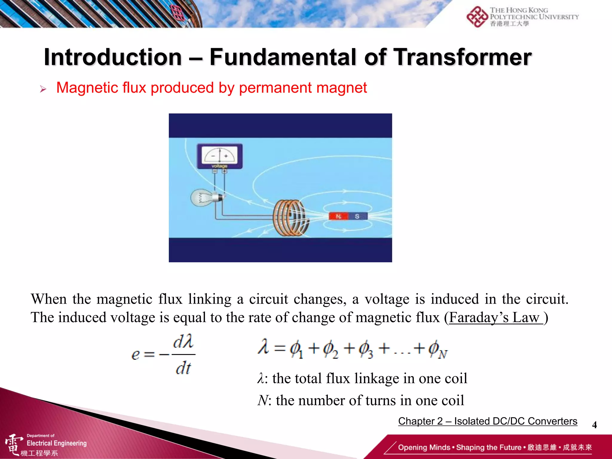
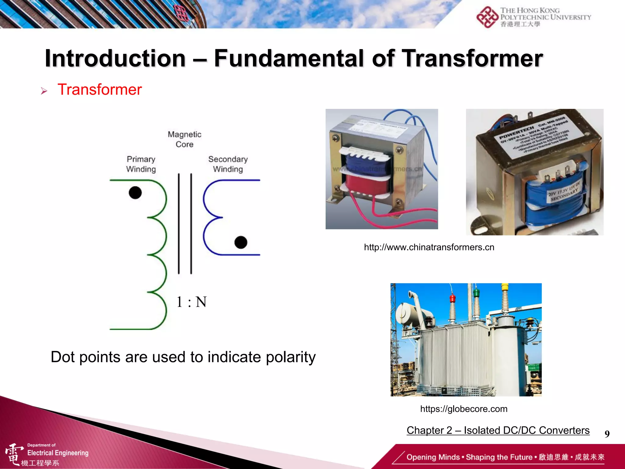
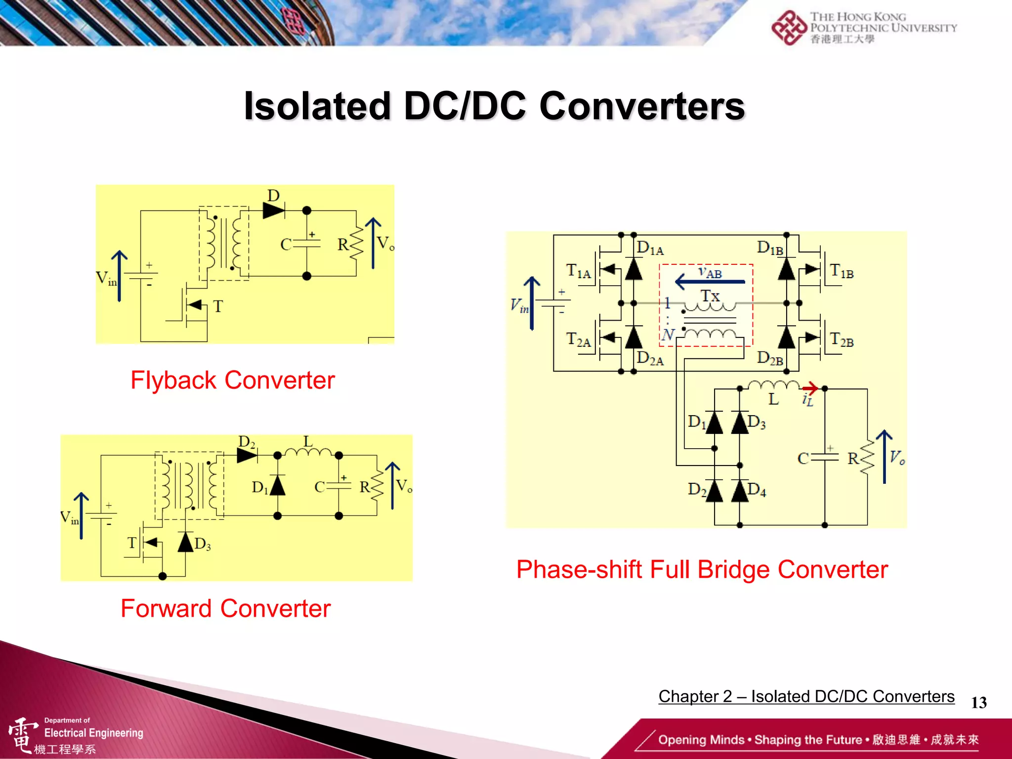
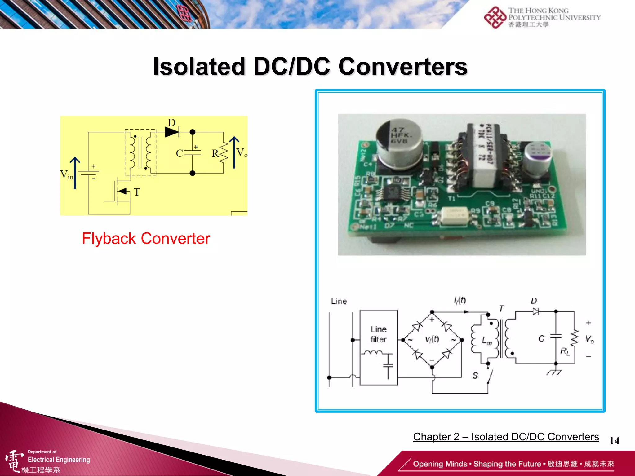
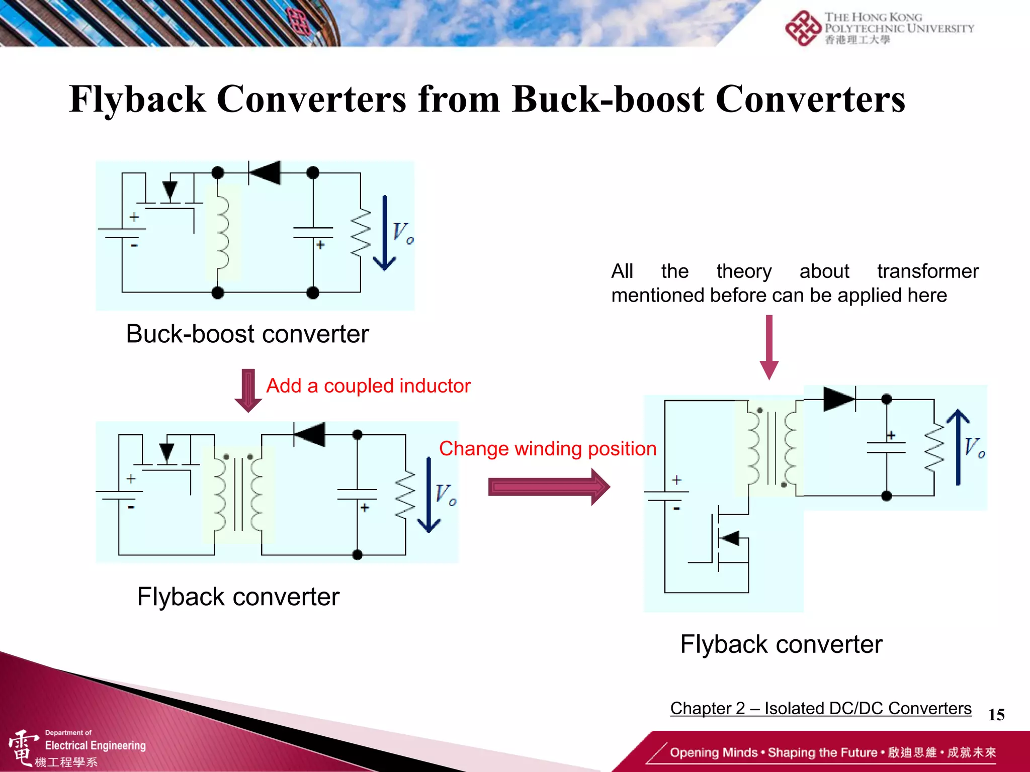
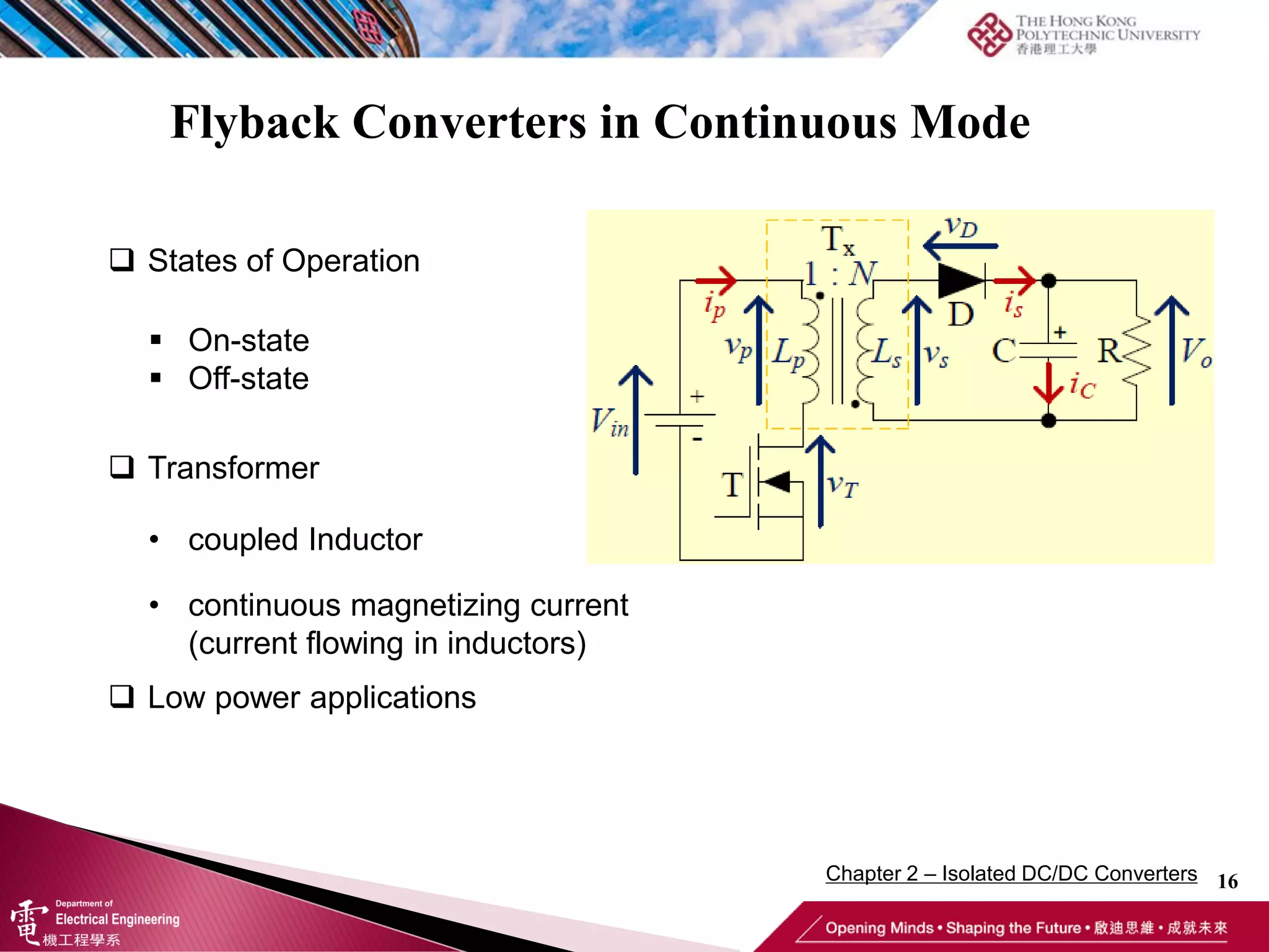
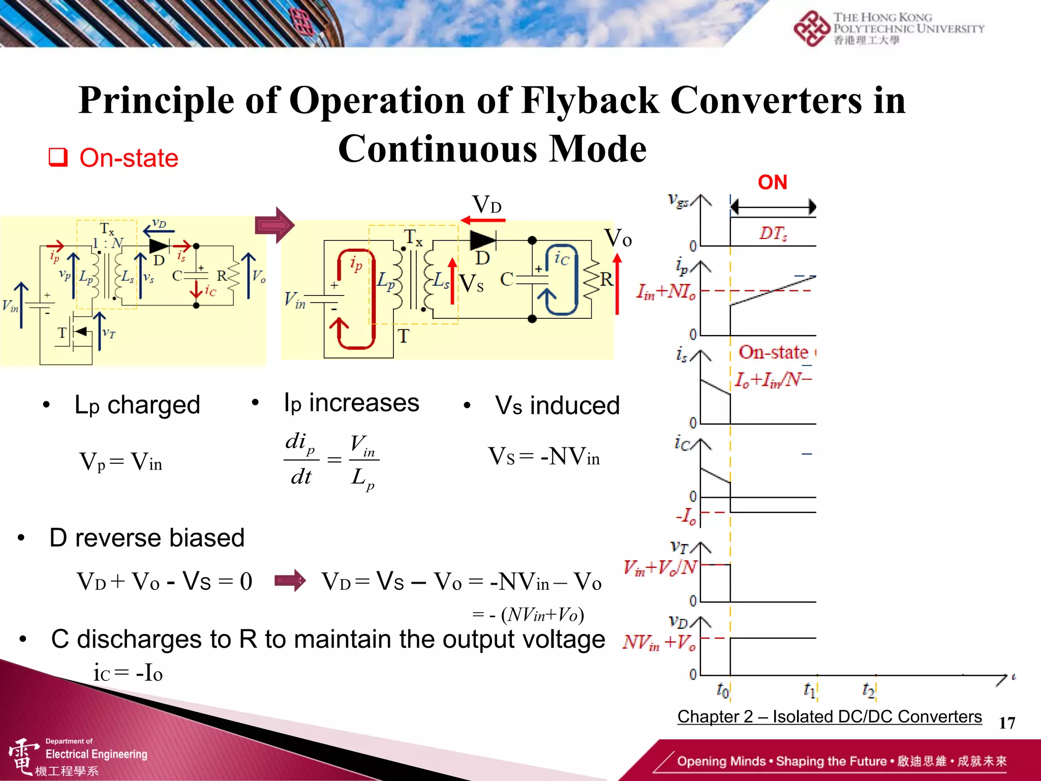
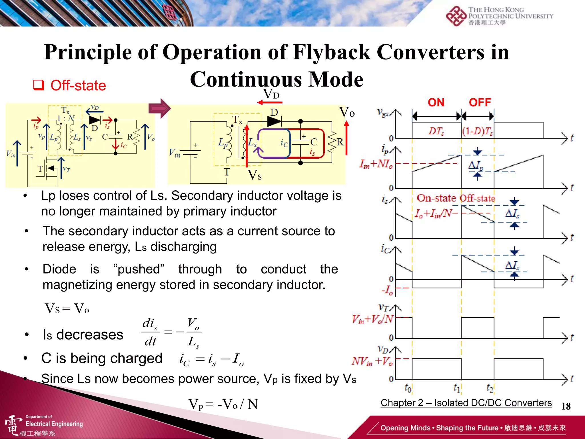
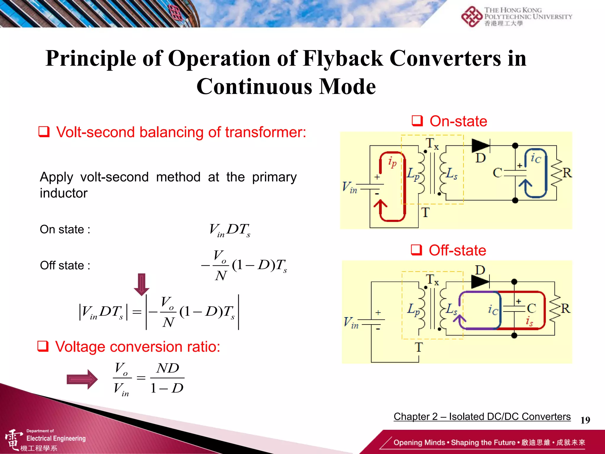
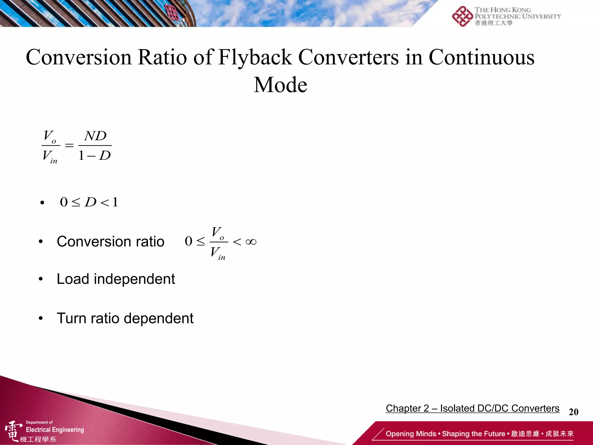
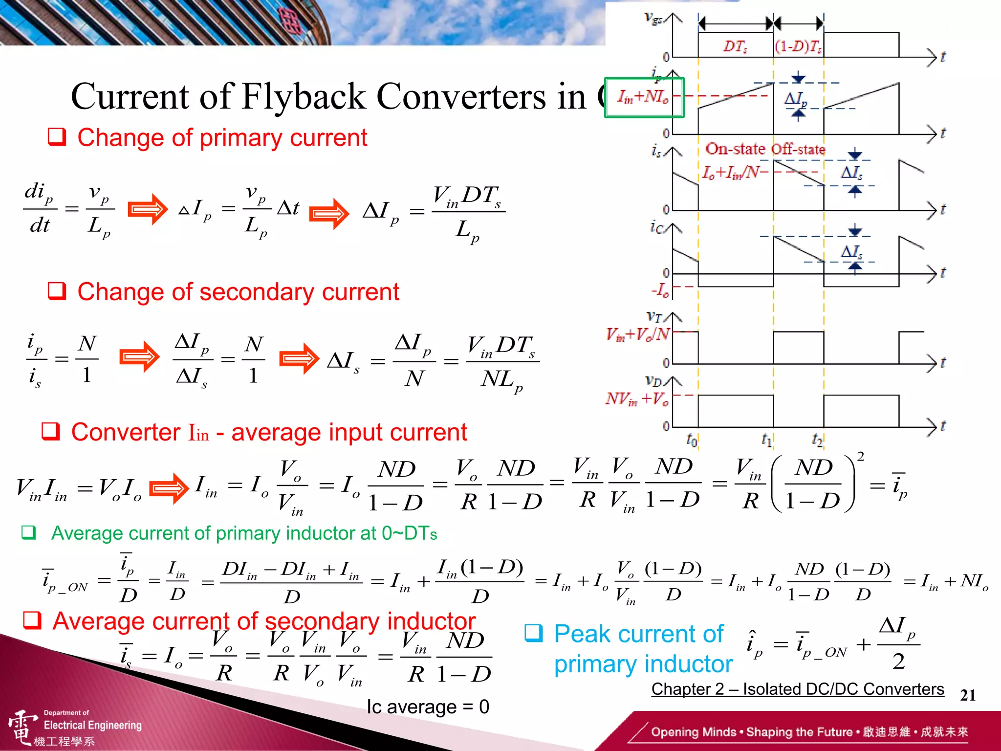
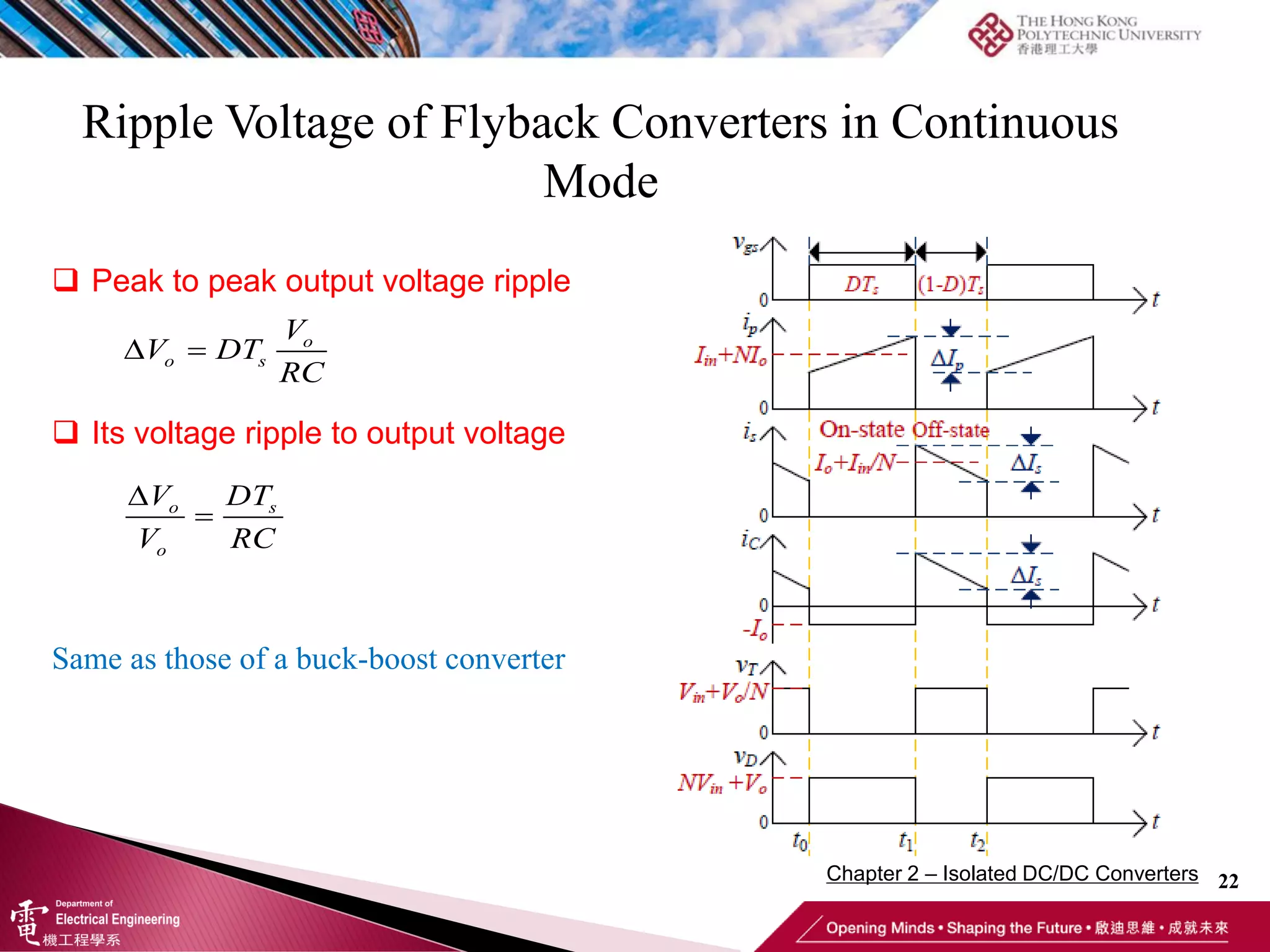
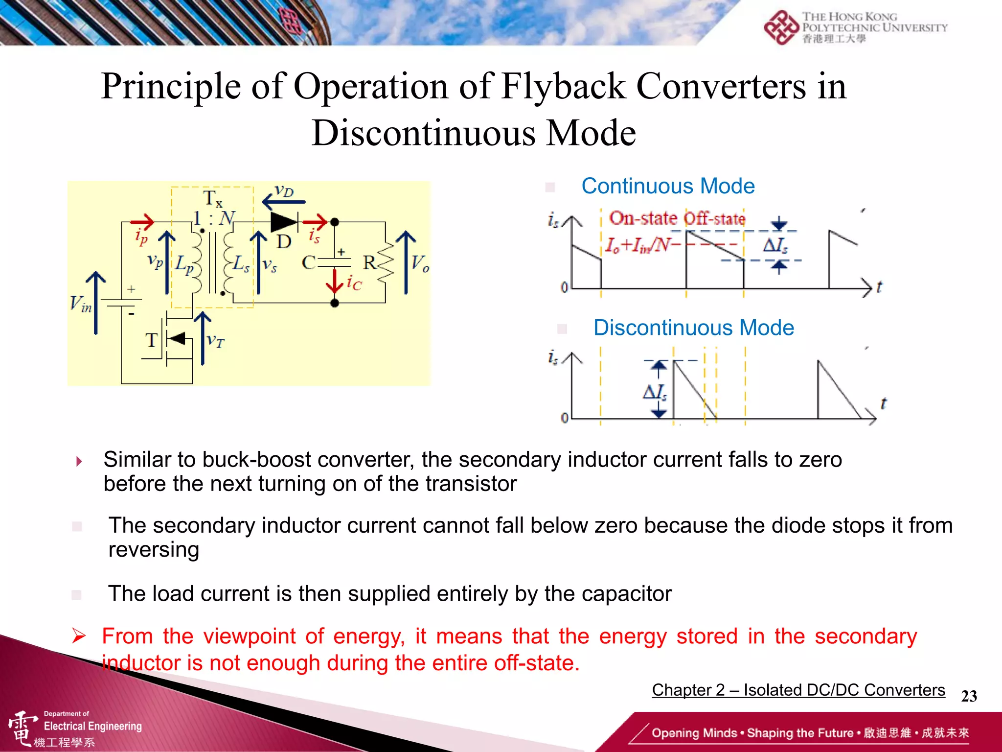
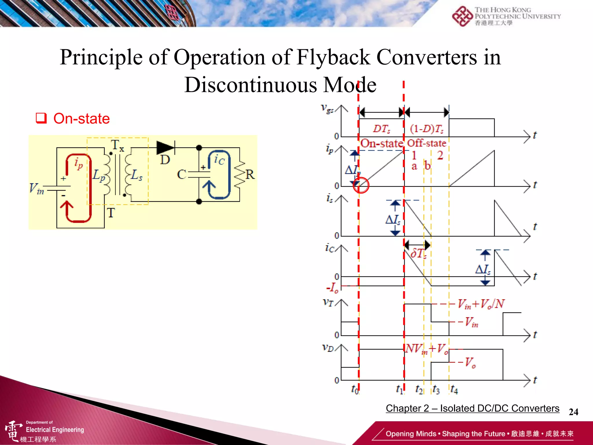
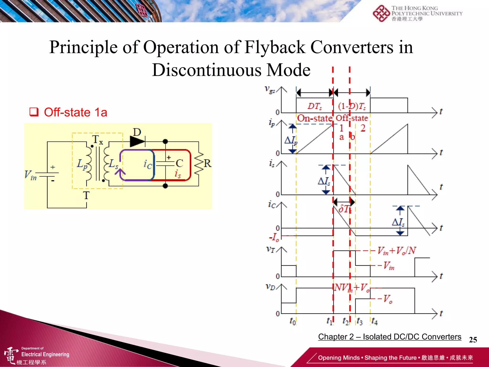
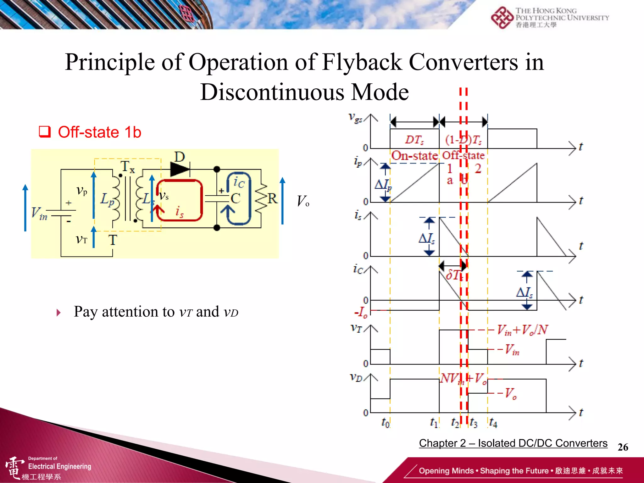
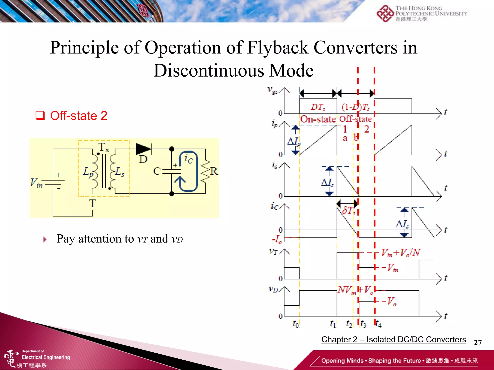
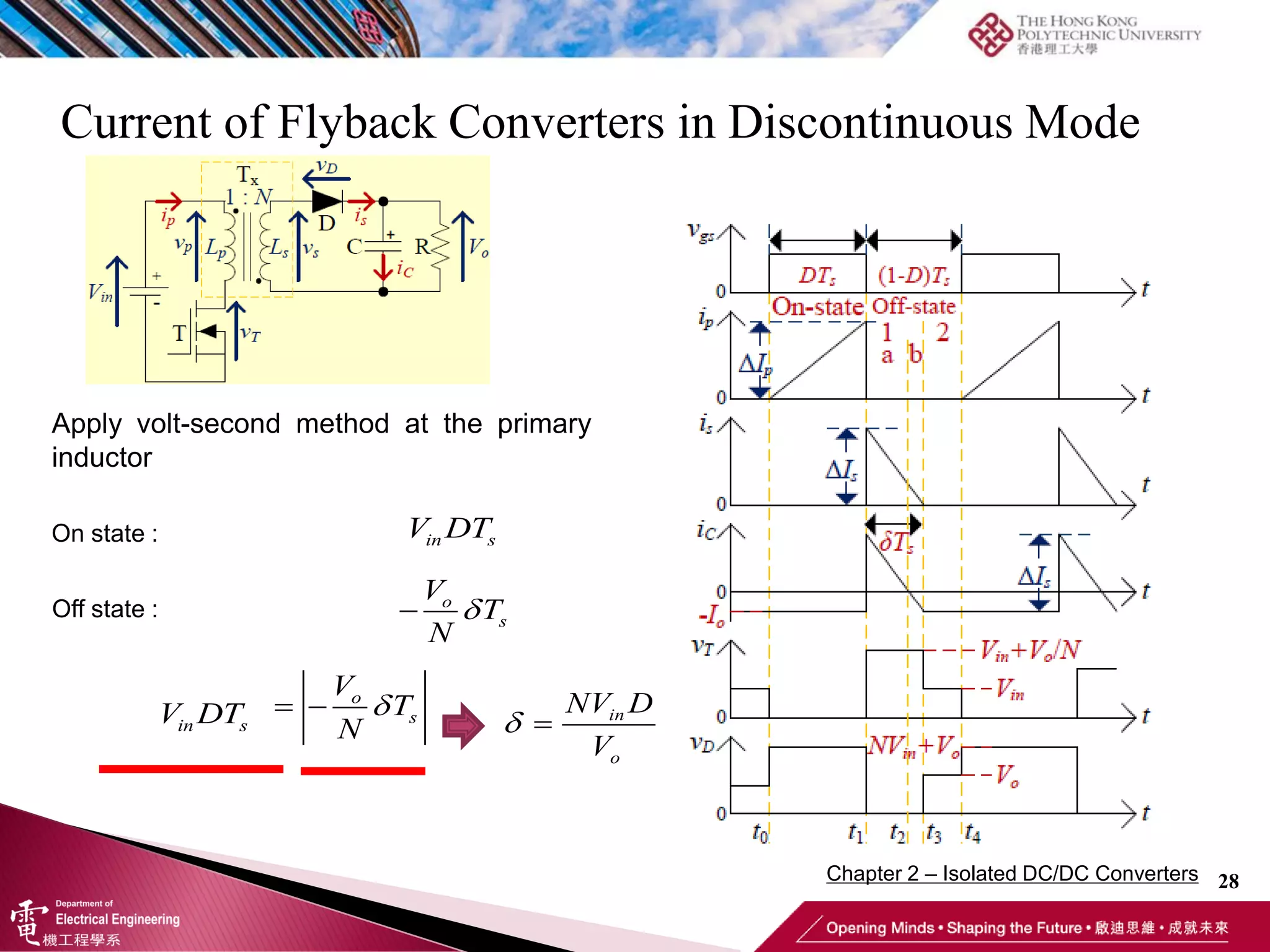
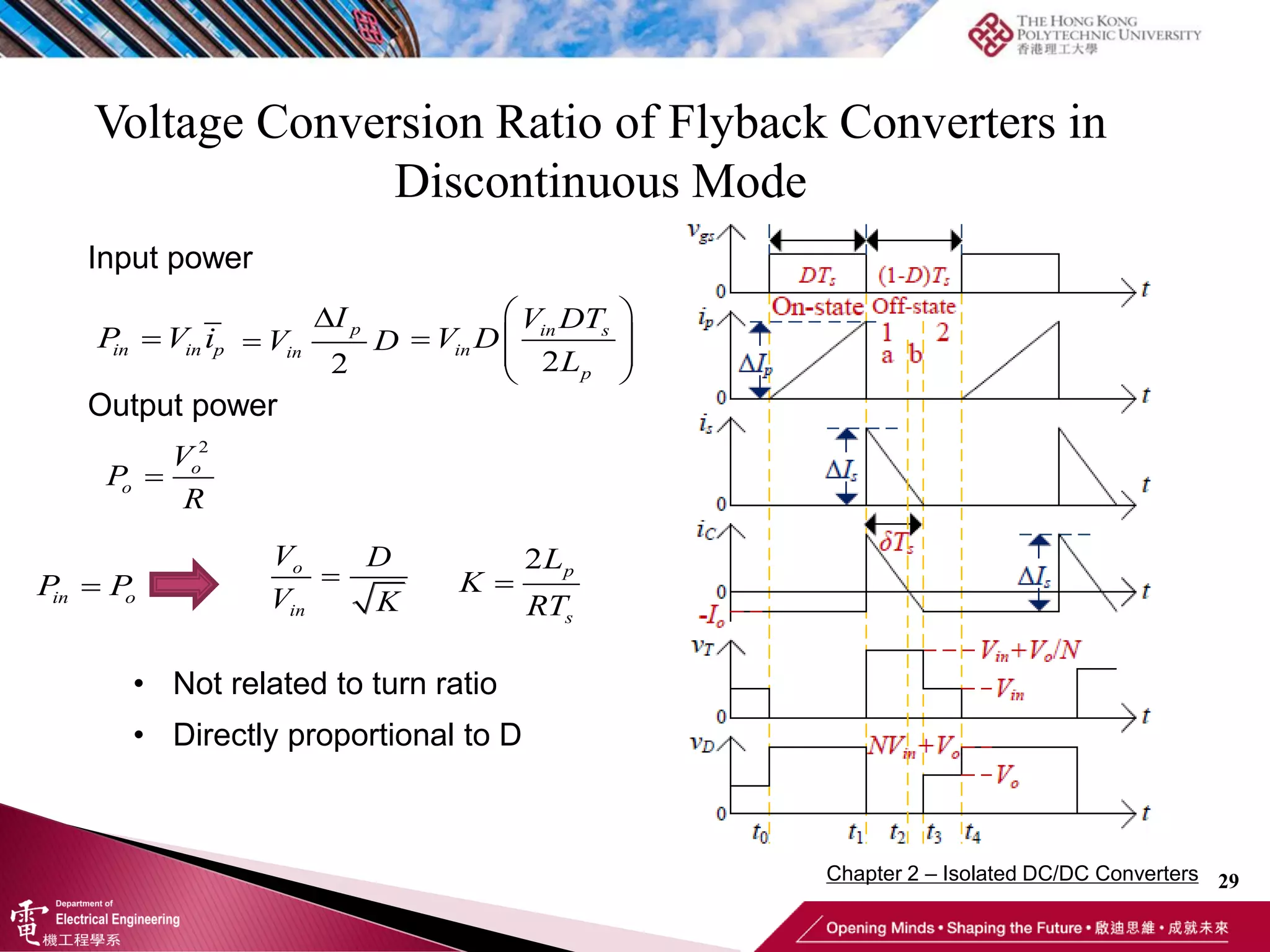
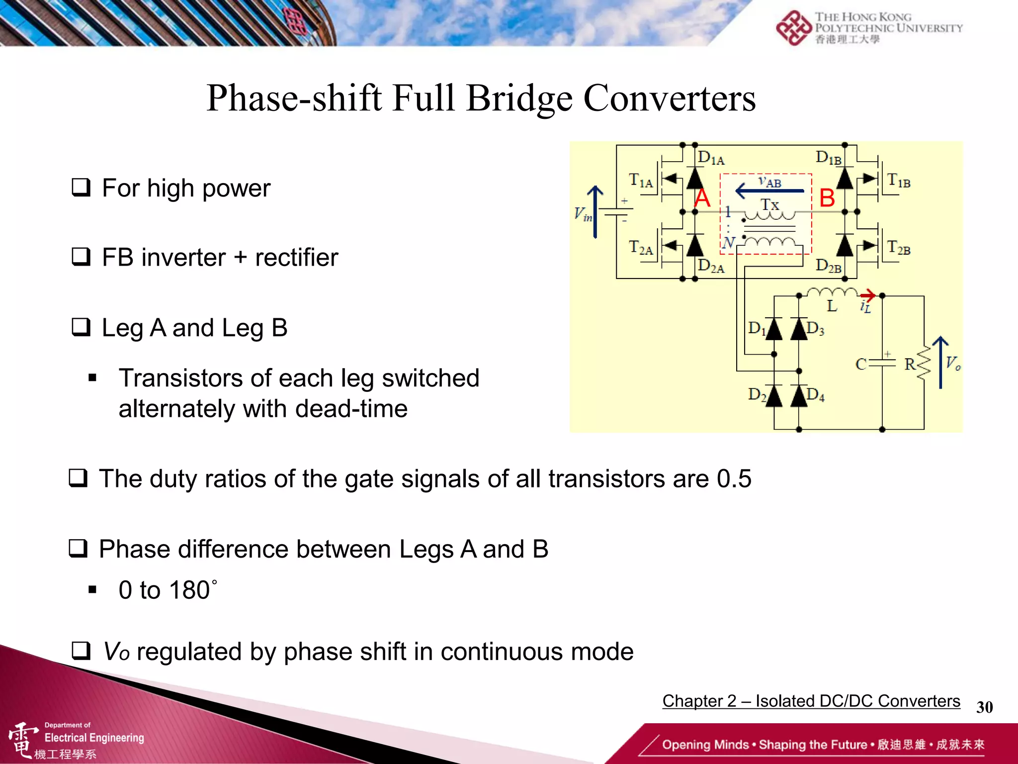
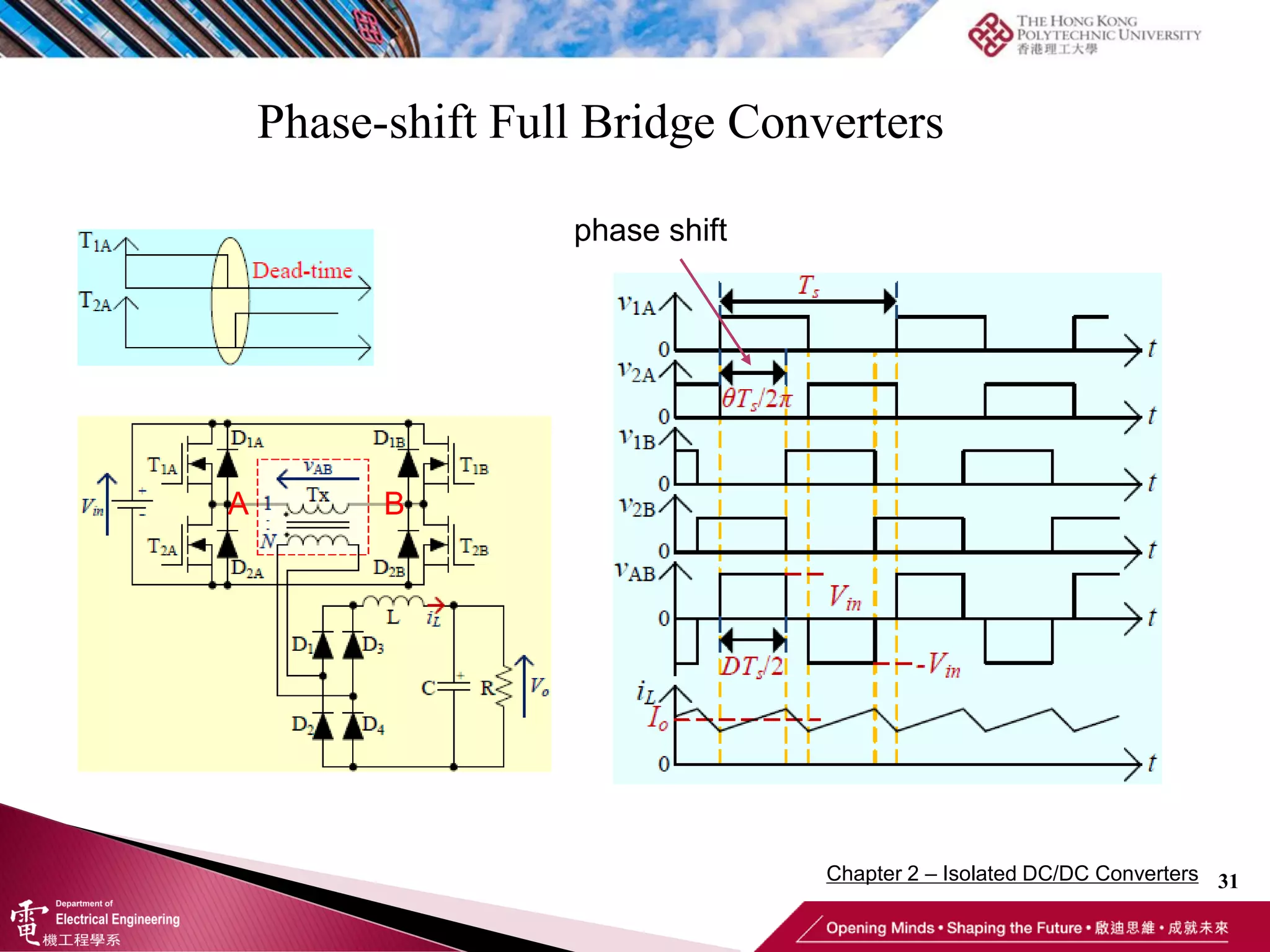
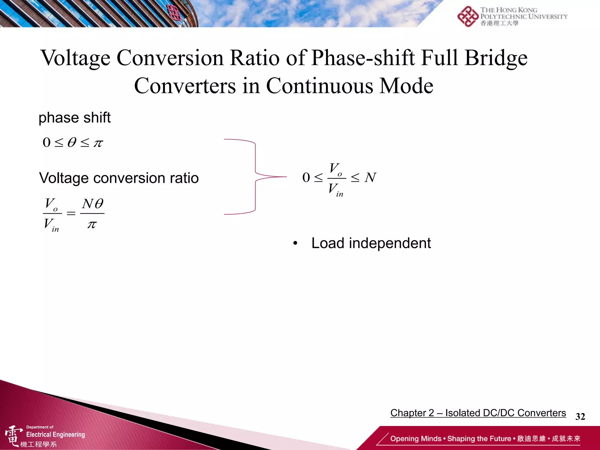
Chapter 2 – Isolated DC/DC Converters
1
Advanced Power Electronics (EE4007A/B/D/4211 )
24-09-2019
Outline
2
Chapter 2 – Isolated DC/DC Converters
 Flyback converters
 Phase-shift converters
 Coupled inductors (Transformer)
Isolated DC/DC Converters
3
 Flyback Converter
 Forward Converter
 Phase Shift Full-bridge Converter
 Single-ended Two-transistor Forward Converter
Chapter 2 – Isolated DC/DC Converters
Introduction – Fundamental of Transformer
4
 Magnetic flux produced by permanent magnet
When the magnetic flux linking a circuit changes, a voltage is induced in the circuit.
The induced voltage is equal to the rate of change of magnetic flux (Faraday’s Law )
λ: the total flux linkage in one coil
N: the number of turns in one coil
Chapter 2 – Isolated DC/DC Converters
Introduction – Fundamental of Transformer
5
 Magnetic flux produced by electrical current
A straight wire with current A coil with current
Chapter 2 – Isolated DC/DC Converters
Introduction – Fundamental of Transformer
6
 Two closely located coils
It consists of a ferromagnetic core and two coils (windings). Each coil is formed by
conductors wrapped like a cylinder. One winding is connected to a source, which is
called the primary.
The source supplies current to the primary winding, which creates a flux in the core.
Most of this flux streams through the core and links the secondary winding. Some of
the flux leaks through the air.
Structure
Phenomenon
Power source Induced voltage
Chapter 2 – Isolated DC/DC Converters
Introduction – Fundamental of Transformer
7
 Two closely located coils
 Physical phenomenon:
• Application: The transformer – coverts the voltage to a higher or lower value
according to the load requirement, i.e., transfers the energy through magnetic flux
Since a time varying flux is linking the secondary winding, there will be an emf
(voltage) induced in that winding. With no load connected to the secondary winding,
the secondary is an open circuit, so there is no current. If load is connected to the
secondary winding, it serves as a voltage source.
Power flow
Power source Induced voltage
Chapter 2 – Isolated DC/DC Converters
Introduction – Fundamental of Transformer
8
 Two closely located coils - Transformer
1 1
2 2
( )

V N
turn ratio
V N
1 2
2 1

I N
I N
• The source voltage can be either AC or DC, as long as the magnetizing current is
changed to produce varying magnetic flux.
• The polarity of the voltage induced at the secondary depends on the winding position
Primary Secondary
+
-
+
-
• The windings (inductors) act as energy storage devices. For example, during t1~t2, power
source is applied at primary, no load is connected at secondary, V2 is induced, i2=0.
During t2~t3, power source is disconnected, load is connected. Then i2 starts to flow.
Chapter 2 – Isolated DC/DC Converters
Introduction – Fundamental of Transformer
9
 Transformer
1 : N
Dot points are used to indicate polarity
https://globecore.com
http://www.chinatransformers.cn
Chapter 2 – Isolated DC/DC Converters
Introduction – Isolated Converters
10
 Features of Isolated DC/DC Converters
 Developed from common non-isolated DC/DC converters
 Built-in high-frequency transformer with ferromagnetic cores
 Electrical isolation
Chapter 2 – Isolated DC/DC Converters
11
 Advantages
 Wide range of voltage conversion ratio
 Electrical isolation
 Low EMI
 Easier to meet international regulations/standards
 Disadvantages
 Higher cost than non-isolated DC/DC Converters
because of transformer
Material cost + manufacturing cost
Introduction – Isolated Converters
Chapter 2 – Isolated DC/DC Converters
12
 Flyback converters, forward converters and phase-shifted converters are
suitable for the applications of low power, medium power and high power,
respectively. Also, Flyback converters and forward converters are able to
operate in both continuous mode and discontinuous mode operations.
 Most common isolated DC/DC Converters
 Flyback converters
• from buck-boost converters
 Forward converters
• from buck converters
 Phase-shift converters
• similar to full-bridge inverters
Introduction – Isolated Converters
Chapter 2 – Isolated DC/DC Converters
Isolated DC/DC Converters
13
Flyback Converter
Forward Converter
Phase-shift Full Bridge Converter
Chapter 2 – Isolated DC/DC Converters
Isolated DC/DC Converters
14
Flyback Converter
Chapter 2 – Isolated DC/DC Converters
Flyback Converters from Buck-boost Converters
15
Buck-boost converter
Flyback converter
Flyback converter
Add a coupled inductor
Change winding position
All the theory about transformer
mentioned before can be applied here
Chapter 2 – Isolated DC/DC Converters
Flyback Converters in Continuous Mode
16
 States of Operation
 On-state
 Off-state
 Transformer
• coupled Inductor
• continuous magnetizing current
(current flowing in inductors)
 Low power applications
Chapter 2 – Isolated DC/DC Converters
Principle of Operation of Flyback Converters in
Continuous Mode
17
 On-state
• D reverse biased
• Lp charged • Ip increases
• C discharges to R to maintain the output voltage
ON OFF
VS = -NVin
Vo
VS
VD
VD + Vo - VS = 0

p in
p
di V
dt L
iC = -Io
VD = VS – Vo = -NVin – Vo
= - (NVin+Vo)
Vp = Vin
• Vs induced
Chapter 2 – Isolated DC/DC Converters
Principle of Operation of Flyback Converters in
Continuous Mode
18
 Off-state
• Is decreases
• C is being charged
ON OFF
• Diode is “pushed” through to conduct the
magnetizing energy stored in secondary inductor.
VS
Vo
VD
• The secondary inductor acts as a current source to
release energy, Ls discharging
VS = Vo
 
s o
s
di V
dt L
• Since Ls now becomes power source, Vp is fixed by Vs
Vp = -Vo / N
 
C s o
i i I
• Lp loses control of Ls. Secondary inductor voltage is
no longer maintained by primary inductor
Chapter 2 – Isolated DC/DC Converters
Principle of Operation of Flyback Converters in
Continuous Mode
19
 Volt-second balancing of transformer:
 Voltage conversion ratio:
1
o
in
V ND
V D


Apply volt-second method at the primary
inductor
On state : in s
V DT
(1 )
 
o
s
V
D T
N
Off state :
(1 )
  
o
in s s
V
V DT D T
N
 On-state
 Off-state
Chapter 2 – Isolated DC/DC Converters
Conversion Ratio of Flyback Converters in Continuous
Mode
20
•
• Conversion ratio 0 o
in
V
V
  
• Load independent
• Turn ratio dependent
1
o
in
V ND
V D


0 1
 
D
Chapter 2 – Isolated DC/DC Converters
Current of Flyback Converters in Continuous Mode
21
in s
p
p
V DT
I
L
 

  
p in s
s
p
I V DT
I
N NL
_
ˆ
2

 
p
p p ON
I
i i
 Change of primary current

p p
p
di v
dt L
 
p
p
p
v
I t
L
 Change of secondary current
1



p
s
I N
I
1
N

p
s
i
i
 Converter Iin - average input current
 p
i

in in o o
V I V I  o
in o
in
V
I I
V 1


o
ND
I
D 1


o
V ND
R D 1


in o
in
V V ND
R V D
2
1
 
  

 
in
V ND
R D
 Peak current of
primary inductor
 Average current of secondary inductor

s o
i I  o
V
R
 o in o
o in
V V V
R V V 1


in
V ND
R D
 Average current of primary inductor at 0~DTs
_ 
p
p ON
i
i
D
 in
I
D
 
 in in in
DI DI I
D
(1 )

  in
in
I D
I
D
(1 )

  o
in o
in
V D
I I
V D
(1 )
1

 

in o
ND D
I I
D D
 
in o
I NI
Ic average = 0
Chapter 2 – Isolated DC/DC Converters
Ripple Voltage of Flyback Converters in Continuous
Mode
22
o
o s
V
V DT
RC
 
o s
o
V DT
V RC


 Peak to peak output voltage ripple
 Its voltage ripple to output voltage
Same as those of a buck-boost converter
Chapter 2 – Isolated DC/DC Converters
Principle of Operation of Flyback Converters in
Discontinuous Mode
23
 Similar to buck-boost converter, the secondary inductor current falls to zero
before the next turning on of the transistor
 From the viewpoint of energy, it means that the energy stored in the secondary
inductor is not enough during the entire off-state.
 The load current is then supplied entirely by the capacitor
 The secondary inductor current cannot fall below zero because the diode stops it from
reversing
 Continuous Mode
 Discontinuous Mode
Chapter 2 – Isolated DC/DC Converters
Principle of Operation of Flyback Converters in
Discontinuous Mode
24
 On-state
Chapter 2 – Isolated DC/DC Converters
Principle of Operation of Flyback Converters in
Discontinuous Mode
25
 Off-state 1a
Chapter 2 – Isolated DC/DC Converters
Principle of Operation of Flyback Converters in
Discontinuous Mode
26
 Off-state 1b
vp
vT
vs
Vo
 Pay attention to vT and vD
Chapter 2 – Isolated DC/DC Converters
Principle of Operation of Flyback Converters in
Discontinuous Mode
27
 Off-state 2
 Pay attention to vT and vD
Chapter 2 – Isolated DC/DC Converters
Current of Flyback Converters in Discontinuous Mode
28
in
o
NV D
V
 
Apply volt-second method at the primary
inductor
On state : in s
V DT
 o
s
V
T
N

Off state :
in s
V DT   o
s
V
T
N

Chapter 2 – Isolated DC/DC Converters
Voltage Conversion Ratio of Flyback Converters in
Discontinuous Mode
29
o
in
V D
V K

• Not related to turn ratio
• Directly proportional to D
2 p
s
L
K
RT


in in p
P V i
2
 
  
 
 
in s
in
p
V DT
V D
L
2


p
in
I
V D
Input power
Output power
2
 o
o
V
P
R

in o
P P
Chapter 2 – Isolated DC/DC Converters
Phase-shift Full Bridge Converters
30
 For high power
 FB inverter + rectifier
 Leg A and Leg B
 Transistors of each leg switched
alternately with dead-time
 Phase difference between Legs A and B
 0 to 180˚
 Vo regulated by phase shift in continuous mode
 The duty ratios of the gate signals of all transistors are 0.5
A B
Chapter 2 – Isolated DC/DC Converters
Phase-shift Full Bridge Converters
31
A B
phase shift
Chapter 2 – Isolated DC/DC Converters
Voltage Conversion Ratio of Phase-shift Full Bridge
Converters in Continuous Mode
32
• Load independent
0  
 
0  
o
in
V
N
V

o
in
V N
V


phase shift
Voltage conversion ratio
Chapter 2 – Isolated DC/DC Converters
Flyback Converter Simulation using
MATLAB/Simulink
33
https://www.youtube.com/watch?v=aNWG4CZucaM
Chapter 2 – Isolated DC/DC Converters

Chapter 2 - Isolated DC-DC Converter.pdf

  • 1.
    Chapter 2 –Isolated DC/DC Converters 1 Advanced Power Electronics (EE4007A/B/D/4211 ) 24-09-2019
  • 2.
    Outline 2 Chapter 2 –Isolated DC/DC Converters  Flyback converters  Phase-shift converters  Coupled inductors (Transformer)
  • 3.
    Isolated DC/DC Converters 3 Flyback Converter  Forward Converter  Phase Shift Full-bridge Converter  Single-ended Two-transistor Forward Converter Chapter 2 – Isolated DC/DC Converters
  • 4.
    Introduction – Fundamentalof Transformer 4  Magnetic flux produced by permanent magnet When the magnetic flux linking a circuit changes, a voltage is induced in the circuit. The induced voltage is equal to the rate of change of magnetic flux (Faraday’s Law ) λ: the total flux linkage in one coil N: the number of turns in one coil Chapter 2 – Isolated DC/DC Converters
  • 5.
    Introduction – Fundamentalof Transformer 5  Magnetic flux produced by electrical current A straight wire with current A coil with current Chapter 2 – Isolated DC/DC Converters
  • 6.
    Introduction – Fundamentalof Transformer 6  Two closely located coils It consists of a ferromagnetic core and two coils (windings). Each coil is formed by conductors wrapped like a cylinder. One winding is connected to a source, which is called the primary. The source supplies current to the primary winding, which creates a flux in the core. Most of this flux streams through the core and links the secondary winding. Some of the flux leaks through the air. Structure Phenomenon Power source Induced voltage Chapter 2 – Isolated DC/DC Converters
  • 7.
    Introduction – Fundamentalof Transformer 7  Two closely located coils  Physical phenomenon: • Application: The transformer – coverts the voltage to a higher or lower value according to the load requirement, i.e., transfers the energy through magnetic flux Since a time varying flux is linking the secondary winding, there will be an emf (voltage) induced in that winding. With no load connected to the secondary winding, the secondary is an open circuit, so there is no current. If load is connected to the secondary winding, it serves as a voltage source. Power flow Power source Induced voltage Chapter 2 – Isolated DC/DC Converters
  • 8.
    Introduction – Fundamentalof Transformer 8  Two closely located coils - Transformer 1 1 2 2 ( )  V N turn ratio V N 1 2 2 1  I N I N • The source voltage can be either AC or DC, as long as the magnetizing current is changed to produce varying magnetic flux. • The polarity of the voltage induced at the secondary depends on the winding position Primary Secondary + - + - • The windings (inductors) act as energy storage devices. For example, during t1~t2, power source is applied at primary, no load is connected at secondary, V2 is induced, i2=0. During t2~t3, power source is disconnected, load is connected. Then i2 starts to flow. Chapter 2 – Isolated DC/DC Converters
  • 9.
    Introduction – Fundamentalof Transformer 9  Transformer 1 : N Dot points are used to indicate polarity https://globecore.com http://www.chinatransformers.cn Chapter 2 – Isolated DC/DC Converters
  • 10.
    Introduction – IsolatedConverters 10  Features of Isolated DC/DC Converters  Developed from common non-isolated DC/DC converters  Built-in high-frequency transformer with ferromagnetic cores  Electrical isolation Chapter 2 – Isolated DC/DC Converters
  • 11.
    11  Advantages  Widerange of voltage conversion ratio  Electrical isolation  Low EMI  Easier to meet international regulations/standards  Disadvantages  Higher cost than non-isolated DC/DC Converters because of transformer Material cost + manufacturing cost Introduction – Isolated Converters Chapter 2 – Isolated DC/DC Converters
  • 12.
    12  Flyback converters,forward converters and phase-shifted converters are suitable for the applications of low power, medium power and high power, respectively. Also, Flyback converters and forward converters are able to operate in both continuous mode and discontinuous mode operations.  Most common isolated DC/DC Converters  Flyback converters • from buck-boost converters  Forward converters • from buck converters  Phase-shift converters • similar to full-bridge inverters Introduction – Isolated Converters Chapter 2 – Isolated DC/DC Converters
  • 13.
    Isolated DC/DC Converters 13 FlybackConverter Forward Converter Phase-shift Full Bridge Converter Chapter 2 – Isolated DC/DC Converters
  • 14.
    Isolated DC/DC Converters 14 FlybackConverter Chapter 2 – Isolated DC/DC Converters
  • 15.
    Flyback Converters fromBuck-boost Converters 15 Buck-boost converter Flyback converter Flyback converter Add a coupled inductor Change winding position All the theory about transformer mentioned before can be applied here Chapter 2 – Isolated DC/DC Converters
  • 16.
    Flyback Converters inContinuous Mode 16  States of Operation  On-state  Off-state  Transformer • coupled Inductor • continuous magnetizing current (current flowing in inductors)  Low power applications Chapter 2 – Isolated DC/DC Converters
  • 17.
    Principle of Operationof Flyback Converters in Continuous Mode 17  On-state • D reverse biased • Lp charged • Ip increases • C discharges to R to maintain the output voltage ON OFF VS = -NVin Vo VS VD VD + Vo - VS = 0  p in p di V dt L iC = -Io VD = VS – Vo = -NVin – Vo = - (NVin+Vo) Vp = Vin • Vs induced Chapter 2 – Isolated DC/DC Converters
  • 18.
    Principle of Operationof Flyback Converters in Continuous Mode 18  Off-state • Is decreases • C is being charged ON OFF • Diode is “pushed” through to conduct the magnetizing energy stored in secondary inductor. VS Vo VD • The secondary inductor acts as a current source to release energy, Ls discharging VS = Vo   s o s di V dt L • Since Ls now becomes power source, Vp is fixed by Vs Vp = -Vo / N   C s o i i I • Lp loses control of Ls. Secondary inductor voltage is no longer maintained by primary inductor Chapter 2 – Isolated DC/DC Converters
  • 19.
    Principle of Operationof Flyback Converters in Continuous Mode 19  Volt-second balancing of transformer:  Voltage conversion ratio: 1 o in V ND V D   Apply volt-second method at the primary inductor On state : in s V DT (1 )   o s V D T N Off state : (1 )    o in s s V V DT D T N  On-state  Off-state Chapter 2 – Isolated DC/DC Converters
  • 20.
    Conversion Ratio ofFlyback Converters in Continuous Mode 20 • • Conversion ratio 0 o in V V    • Load independent • Turn ratio dependent 1 o in V ND V D   0 1   D Chapter 2 – Isolated DC/DC Converters
  • 21.
    Current of FlybackConverters in Continuous Mode 21 in s p p V DT I L       p in s s p I V DT I N NL _ ˆ 2    p p p ON I i i  Change of primary current  p p p di v dt L   p p p v I t L  Change of secondary current 1    p s I N I 1 N  p s i i  Converter Iin - average input current  p i  in in o o V I V I  o in o in V I I V 1   o ND I D 1   o V ND R D 1   in o in V V ND R V D 2 1         in V ND R D  Peak current of primary inductor  Average current of secondary inductor  s o i I  o V R  o in o o in V V V R V V 1   in V ND R D  Average current of primary inductor at 0~DTs _  p p ON i i D  in I D    in in in DI DI I D (1 )    in in I D I D (1 )    o in o in V D I I V D (1 ) 1     in o ND D I I D D   in o I NI Ic average = 0 Chapter 2 – Isolated DC/DC Converters
  • 22.
    Ripple Voltage ofFlyback Converters in Continuous Mode 22 o o s V V DT RC   o s o V DT V RC    Peak to peak output voltage ripple  Its voltage ripple to output voltage Same as those of a buck-boost converter Chapter 2 – Isolated DC/DC Converters
  • 23.
    Principle of Operationof Flyback Converters in Discontinuous Mode 23  Similar to buck-boost converter, the secondary inductor current falls to zero before the next turning on of the transistor  From the viewpoint of energy, it means that the energy stored in the secondary inductor is not enough during the entire off-state.  The load current is then supplied entirely by the capacitor  The secondary inductor current cannot fall below zero because the diode stops it from reversing  Continuous Mode  Discontinuous Mode Chapter 2 – Isolated DC/DC Converters
  • 24.
    Principle of Operationof Flyback Converters in Discontinuous Mode 24  On-state Chapter 2 – Isolated DC/DC Converters
  • 25.
    Principle of Operationof Flyback Converters in Discontinuous Mode 25  Off-state 1a Chapter 2 – Isolated DC/DC Converters
  • 26.
    Principle of Operationof Flyback Converters in Discontinuous Mode 26  Off-state 1b vp vT vs Vo  Pay attention to vT and vD Chapter 2 – Isolated DC/DC Converters
  • 27.
    Principle of Operationof Flyback Converters in Discontinuous Mode 27  Off-state 2  Pay attention to vT and vD Chapter 2 – Isolated DC/DC Converters
  • 28.
    Current of FlybackConverters in Discontinuous Mode 28 in o NV D V   Apply volt-second method at the primary inductor On state : in s V DT  o s V T N  Off state : in s V DT   o s V T N  Chapter 2 – Isolated DC/DC Converters
  • 29.
    Voltage Conversion Ratioof Flyback Converters in Discontinuous Mode 29 o in V D V K  • Not related to turn ratio • Directly proportional to D 2 p s L K RT   in in p P V i 2          in s in p V DT V D L 2   p in I V D Input power Output power 2  o o V P R  in o P P Chapter 2 – Isolated DC/DC Converters
  • 30.
    Phase-shift Full BridgeConverters 30  For high power  FB inverter + rectifier  Leg A and Leg B  Transistors of each leg switched alternately with dead-time  Phase difference between Legs A and B  0 to 180˚  Vo regulated by phase shift in continuous mode  The duty ratios of the gate signals of all transistors are 0.5 A B Chapter 2 – Isolated DC/DC Converters
  • 31.
    Phase-shift Full BridgeConverters 31 A B phase shift Chapter 2 – Isolated DC/DC Converters
  • 32.
    Voltage Conversion Ratioof Phase-shift Full Bridge Converters in Continuous Mode 32 • Load independent 0     0   o in V N V  o in V N V   phase shift Voltage conversion ratio Chapter 2 – Isolated DC/DC Converters
  • 33.
    Flyback Converter Simulationusing MATLAB/Simulink 33 https://www.youtube.com/watch?v=aNWG4CZucaM Chapter 2 – Isolated DC/DC Converters