More Related Content
Similar to celulares 2.pdf (7)
celulares 2.pdf
- 1. Nokia E5-00
RM-632 / RM-634
Disassembly and Assembly
1 Confidential • Copyright © 2010 NOKIA • All rights reserved Version 2.0
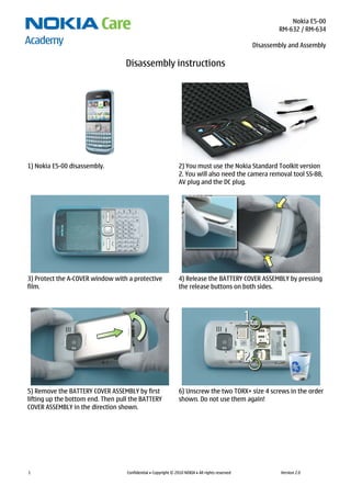
Disassembly instructions
1) Nokia E5-00 disassembly. 2) You must use the Nokia Standard Toolkit version
2. You will also need the camera removal tool SS-88,
AV plug and the DC plug.
3) Protect the A-COVER window with a protective
film.
4) Release the BATTERY COVER ASSEMBLY by pressing
the release buttons on both sides.
5) Remove the BATTERY COVER ASSEMBLY by first
lifting up the bottom end. Then pull the BATTERY
COVER ASSEMBLY in the direction shown.
6) Unscrew the two TORX+ size 4 screws in the order
shown. Do not use them again!
- 2. Nokia E5-00
RM-632 / RM-634
Disassembly and Assembly
2 Confidential • Copyright © 2010 NOKIA • All rights reserved Version 2.0
7) To detach the A-COVER ASSEMBLY, first release the
three clips on the left side by sliding the SRT-6 to
the direction shown.
8) Then release the two clips on the bottom side.
9) Continue to slide the SRT-6 in the direction
shown to release the three clips on the right side.
10) Finally release the two clips on the top side.
11) The display gasket in the A-COVER is lightly
glued to the LCD. Loosen the adhesive by carefully
lifting up the A-COVER. The A-COVER can now be
separated.
12) Protect the LCD with a protective film.
- 3. Nokia E5-00
RM-632 / RM-634
Disassembly and Assembly
3 Confidential • Copyright © 2010 NOKIA • All rights reserved Version 2.0
13) Release the clips holding the MAIN KEYMAT on
both sides.
14) Lift up the bottom end of the MAIN KEYMAT. Pull
out the MAIN KEYMAT in the direction shown and
remove it.
15) Use the SS-93 to release the EARPIECE. 16) Remove the EARPIECE with the tweezers. Do not
use it again.
17) Use the tweezers to remove the EARPIECE FRONT
GASKET. Discard the EARPIECE FRONT GASKET.
18) Unscrew the four TORX+ size 6 screws in the
order shown. Note that these screws can be reused.
Do not discard them!
- 4. Nokia E5-00
RM-632 / RM-634
Disassembly and Assembly
4 Confidential • Copyright © 2010 NOKIA • All rights reserved Version 2.0
19) Release the clip holding the LOCKING PLATE
ASSEMBLY with the tweezers. Lift up the locking
plate as shown.
20) Remove the LOCKING PLATE ASSEMBLY with the
tweezers.
21) Open the USB PLUG. 22) To remove the LIGHT SWAP PWB, use the SS-93
to release the first clip …
23) … and the second clip on the other side holding
the LIGHT SWAP PWB.
24) Lift up the LIGHT SWAP PWB and remove it.
- 5. Nokia E5-00
RM-632 / RM-634
Disassembly and Assembly
5 Confidential • Copyright © 2010 NOKIA • All rights reserved Version 2.0
25) To release the MAIN ANTENNA ASSEMBLY, pull it
to the direction shown.
26) Remove the MAIN ANTENNA ASSEMBLY.
27) Use the SS-93 to open the LCD CONNECTOR.
Be careful not to damage the connector!
28) Release the two clips holding the DISPLAY
SUPPORT ASSEMBLY with the SS-93.
29) Separate the DISPLAY SUPPORT ASSEMBLY. 30) Push the camera removal tool SS-88 down until
the camera retaining clips are released. Lift up the
SS-88 and remove the CAMERA MODULE.
- 6. Nokia E5-00
RM-632 / RM-634
Disassembly and Assembly
6 Confidential • Copyright © 2010 NOKIA • All rights reserved Version 2.0
31) To release the LCD, use the dental tool to
carefully loosen the adhesive. Be careful not to
break the LCD or injure yourself with the sharp end
of the dental tool!
32) Remove the DISPLAY SUPPORT ASSEMBLY. Do not
use it again.
33) Remove the adhesive from the LCD with the
tweezers. Do not use the adhesive again.
34) Use the SS-93 to lift up one corner of the
DOMESHEET.
35) Peel off and remove the DOMESHEET. Discard the
removed DOMESHEET.
36) Use the SS-93 to release the IHF SPEAKER.
Remove the IHF SPEAKER with the tweezers. Do not
use it again.
- 7. Nokia E5-00
RM-632 / RM-634
Disassembly and Assembly
7 Confidential • Copyright © 2010 NOKIA • All rights reserved Version 2.0
37) Use the tweezers to remove the IHF SPEAKER
GASKET. Do not use it again.
38) Use the SS-93 to carefully release the clip
holding the NCW ANTENNA. Lift up the NCW
ANTENNA with the SS-93.
39) Remove the NCW ANTENNA. 40) Release the DC JACK with the DC plug and
remove it with the tweezers.
41) Release the AV JACK with the AV plug and
remove it with the tweezers.
42) Nokia E5-00 disassembly is now complete.
-END OF DISASSEMBLY-
- 8. Nokia E5-00
RM-632 / RM-634
Disassembly and Assembly
8 Confidential • Copyright © 2010 NOKIA • All rights reserved Version 2.0
Assembly hints
1) Connect the LCD connector to the engine board. 2) Use the SS-93 to carefully bend the LCD flex while
pushing the LCD carefully forward.
3) Position the top clip and carefully press down
the LCD flex.
4) Press down the clips on both sides.
5) Slide the LOCKING PLATE ASSEMBLY between the
LCD connector and the bent flex. Press down the
shown clip to lock the LOCKING PLATE ASSEMBLY.
6) Tighten the four TORX + size 6 screws to the
torque of 13 Ncm in the order shown.
- 9. Nokia E5-00
RM-632 / RM-634
Disassembly and Assembly
9 Confidential • Copyright © 2010 NOKIA • All rights reserved Version 2.0
7) Tighten the two TORX + size 4 screws to the
torque of 14 Ncm in the order shown.