Downloaded 166 times

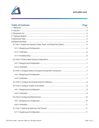


The document outlines a comprehensive CCNA lab focused on configuring EtherChannels and optimizing Spanning Tree Protocol (STP) on Cisco switches. It includes objectives, scenarios, and detailed steps for setting up network topology, device configurations, VLANs, and verification processes. The lab is structured in multiple parts, guiding users through preparation, configurations, and troubleshooting for a successful lab experience.