Downloaded 124 times

![amir-jafari.com
©2015 Amir Jafari – www.amir-Jafari.com. All rights reserved. Page 9 of 10
S1(config)#line vty 0 15
S1(config-line)#login local
S1(config-line)#exit
Step 3: Creates a host domain for the Switch
To work, SSH requires a local IP domain.
S1(config)#ip domain-name cisco.com
Step 4: Create the encryption keys
Enables the SSH server for local and remote authentication on the switch and generates an RSA key pair.
S1(config)#crypto key generate rsa
How many bits in the modulus [512]: 1024
Step 5: Enable SSH Version 2
S1(config)#ip ssh version 2
Step 6: Disable support for inbound Telnet connections
The switch supports both Telnet and SSH on the vty lines, but you can disable Telnet for tighter security.
S1(config)#line vty 0 15
S1(config-line)#transport input ssh
6-3-2- Verification
Step 1: Examine the running configuration file
S1#show running-config
Step 2: The status information about the SSH server
The show ip ssh command lists status information about the SSH server itself.
S1#show ip ssh](https://image.slidesharecdn.com/ccnalab2-configuringaswitchpartii-150831070100-lva1-app6892/85/CCNA-Lab-2-Configuring-a-Switch-Part-II-9-320.jpg)
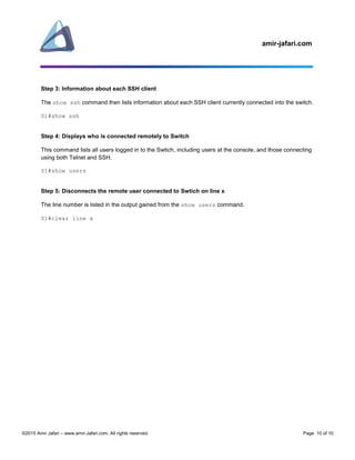

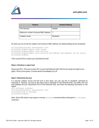
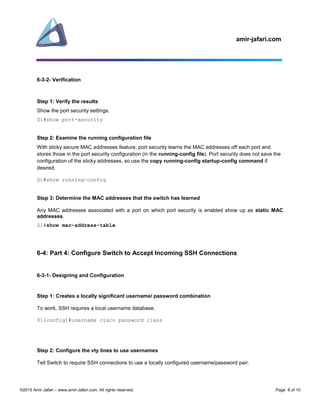
This document provides instructions for configuring a Cisco switch, including: 1) Configuring basic port security to restrict access to specific ports and MAC addresses. 2) Enabling SSH on the switch to allow remote access and disabling Telnet for security. 3) Verification steps like showing port security settings, SSH status, and connected users.