
Recommended
More Related Content
Similar to Caterpillar Cat TH460B Telehandler (Prefix SLF) Service Repair Manual Instant Download (SLF00001 and up).pdf
Similar to Caterpillar Cat TH460B Telehandler (Prefix SLF) Service Repair Manual Instant Download (SLF00001 and up).pdf (14)
More from taishang3939
More from taishang3939 (20)
Recently uploaded
Recently uploaded (17)
Caterpillar Cat TH460B Telehandler (Prefix SLF) Service Repair Manual Instant Download (SLF00001 and up).pdf
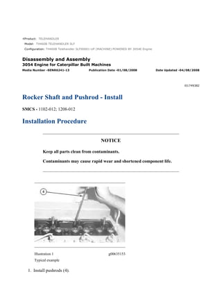
- 1. Product: TELEHANDLER Model: TH460B TELEHANDLER SLF Configuration: TH460B Telehandler SLF00001-UP (MACHINE) POWERED BY 3054E Engine Disassembly and Assembly 3054 Engine for Caterpillar Built Machines Media Number -SENR6241-13 Publication Date -01/08/2008 Date Updated -04/08/2008 i01749382 Rocker Shaft and Pushrod - Install SMCS - 1102-012; 1208-012 Installation Procedure NOTICE Keep all parts clean from contaminants. Contaminants may cause rapid wear and shortened component life. Illustration 1 g00635153 Typical example 1. Install pushrods (4). 1/2(W) w 2022/5/12 https://127.0.0.1/sisweb/sisweb/techdoc/techdoc_print_page.jsp?returnurl=/sisweb/sisw...
- 2. Note: Ensure that the pushrods are installed in the original location and that the pushrods are seated in the valve lifters correctly. 2. Install a new oil seal in the oil supply hole in the cylinder head. Illustration 2 g00635152 Typical example 3. Put rocker shaft assembly (3) in position on the cylinder head. Make sure that the connection for the oil supply is installed correctly into the oil seal. Note: Ensure that the adjustment screws are properly seated in the ends of pushrods (4). Note: It may be necessary to loosen the adjustment screws on each rocker arm. This will help prevent a bent valve or a bent pushrod during the installation of the rocker shaft. 4. Lubricate nuts (1) and bolt (2) with clean engine oil. 5. Install nuts (1) and bolt (2). 6. Alternately tighten the nuts and the bolt. Start from the center and work toward the outside. Tighten the nuts and the bolt on an aluminum bracket to a torque of 40 N·m (30 lb ft). Tighten the nuts and the bolt on a cast iron or a steel bracket to a torque of 75 N·m (55 lb ft). 7. Adjust the inlet valve lash to 0.20 mm (0.008 inch) and adjust the exhaust valve lash to 0.45 mm (0.018 inch). Refer to Testing and Adjusting, "Air Inlet and Exhaust System" for more information on adjusting the valve lash. End By: a. Install the valve mechanism cover. Refer to Disassembly and Assembly, "Valve Mechanism Cover - Remove and Install". 2/2(W) w 2022/5/12 https://127.0.0.1/sisweb/sisweb/techdoc/techdoc_print_page.jsp?returnurl=/sisweb/sisw...
- 3. Product: TELEHANDLER Model: TH460B TELEHANDLER SLF Configuration: TH460B Telehandler SLF00001-UP (MACHINE) POWERED BY 3054E Engine Disassembly and Assembly 3054 Engine for Caterpillar Built Machines Media Number -SENR6241-13 Publication Date -01/08/2008 Date Updated -04/08/2008 i01645897 Cylinder Head - Remove SMCS - 1100-011 Removal Procedure Start By: A. Disconnect the electrical connections at the battery. B. Drain the coolant system. If the engine uses Diesel Engine Antifreeze/Coolant (DEAC), refer to Operation and Maintenance Manual, "Cooling System Coolant (DEAC) - Change". If the engine uses Extended Life Coolant (ELC), refer to Operation and Maintenance Manual, "Cooling System Coolant (ELC) - Change". C. Remove the air inlet manifold. Refer to Disassembly and Assembly, "Air Inlet Manifold - Remove". D. Remove the exhaust manifold. Refer to Disassembly and Assembly, "Exhaust Manifold - Remove and Install". E. Remove the fuel injection nozzles. Refer to Disassembly and Assembly, "Fuel Injection Nozzles - Remove". F. Remove the fuel filter base. Refer to Disassembly and Assembly, "Fuel Filter Base - Remove and Install". G. Remove the water outlet manifold. Refer to Disassembly and Assembly, "Water Outlet Manifold - Remove". H. Remove the rocker shaft assembly and the pushrods. Refer to Disassembly and Assembly, "Rocker Arm and Shaft - Remove". 1/4(W) w 2022/5/12 https://127.0.0.1/sisweb/sisweb/techdoc/techdoc_print_page.jsp?returnurl=/sisweb/sisw...
- 4. Illustration 1 g00550160 Typical example Illustration 2 g00550162 1. Gradually loosen 22 cylinder head bolts (1) in the reverse order that is shown in Illustration 2. This will help prevent distortion of the cylinder head. 2/4(W) w 2022/5/12 https://127.0.0.1/sisweb/sisweb/techdoc/techdoc_print_page.jsp?returnurl=/sisweb/sisw...
- 5. Illustration 3 g00550163 Typical example 2. Attach a suitable lifting device to cylinder head (2). Carefully lift cylinder head (2) off the engine block. The weight of the cylinder head is 41 kg (90 lb). NOTICE Place the cylinder head on a surface that will not scratch the face of the cylinder head. Illustration 4 g00550165 3. Remove cylinder head gasket (3) . 4. Note the location of dowels (4) on each end of the cylinder block. Dowels (4) hold cylinder head gasket (3) in place while cylinder head (2) is installed. 3/4(W) w 2022/5/12 https://127.0.0.1/sisweb/sisweb/techdoc/techdoc_print_page.jsp?returnurl=/sisweb/sisw...
- 6. Illustration 5 g00741112 5. Align straight edge (7) with bolt (6) in order to check for distortion. If there is a visible reduction in the diameter of thread (8) that has not been in engagement with the cylinder block, the bolts must be replaced. 4/4(W) w 2022/5/12 https://127.0.0.1/sisweb/sisweb/techdoc/techdoc_print_page.jsp?returnurl=/sisweb/sisw...
- 7. Product: TELEHANDLER Model: TH460B TELEHANDLER SLF Configuration: TH460B Telehandler SLF00001-UP (MACHINE) POWERED BY 3054E Engine Disassembly and Assembly 3054 Engine for Caterpillar Built Machines Media Number -SENR6241-13 Publication Date -01/08/2008 Date Updated -04/08/2008 i01645901 Cylinder Head - Install SMCS - 1100-012 Installation Procedure Table 1 Required Tools Tool Part Number Part Description Qty A 9U-6238 Guide Bolt 2 B 8T-3052 Degree Wheel 1 1. Thoroughly clean the top of the cylinder block and the bottom of the cylinder head. Ensure that there is no debris in the cylinder bores. Illustration 1 g00550165 1/4(W) w 2022/5/12 https://127.0.0.1/sisweb/sisweb/techdoc/techdoc_print_page.jsp?returnurl=/sisweb/sisw...
- 8. 2. Place cylinder head gasket (3) on dowels (4) on top of the cylinder block. The cylinder head gasket (3) is stamped "FRONT TOP". Do not use any sealant or compound on the cylinder head gasket. 3. Install Tool (A) in positions 15 and 20 in the cylinder block. Refer to Illustration 4. Illustration 2 g00550163 Typical example 4. Attach a suitable lifting device to cylinder head (2) . 5. Place cylinder head (2) on the cylinder block. Ensure that the cylinder head is positioned on dowels (4) and that cylinder head gasket (3) is positioned correctly. 6. Remove Tool (A) . Illustration 3 g00550160 Typical example 7. Lubricate cylinder head bolts (1) with clean engine oil. 2/4(W) w 2022/5/12 https://127.0.0.1/sisweb/sisweb/techdoc/techdoc_print_page.jsp?returnurl=/sisweb/sisw...
- 9. Illustration 4 g00550162 8. Gradually tighten all of the bolts (1 through 22) in a numerical sequence to a torque of 110 N·m (80 lb ft). 9. Tighten all of the bolts (1 through 22) again in a numerical sequence to a torque of 110 N·m (80 lb ft). 10. Place an index mark on the bolts and use Tool (B) in order to further tighten the bolts. Refer to illustration 4. a. Turn the short bolts that are marked with an "S" for an additional 150 degrees (2.5 flats). b. Turn the medium length bolts that are marked with an "M" for an additional 180 degrees (3.0 flats). c. Turn the long bolts that are marked with an "L" for an additional 210 degrees (3.5 flats). End By: a. Install the rocker shaft assembly. Refer to Disassembly and Assembly, "Rocker Arm and Shaft - Install". b. Install the water outlet manifold. Refer to Disassembly and Assembly, "Water Outlet Manifold - Install". c. Install the fuel filter base. Refer to Disassembly and Assembly, "Fuel Filter Base - Remove and Install". d. Install the fuel injection nozzles. Refer to Disassembly and Assembly, "Fuel Injection Nozzles - Install". e. Install the exhaust manifold. Refer to Disassembly and Assembly, "Exhaust Manifold - Remove and Install". f. Install the inlet manifold. Refer to Disassembly and Assembly, "Air inlet Manifold -Install". 3/4(W) w 2022/5/12 https://127.0.0.1/sisweb/sisweb/techdoc/techdoc_print_page.jsp?returnurl=/sisweb/sisw...
- 10. g. Fill the coolant system. If the engine uses Extended Life Coolant (ELC), refer to Operation and Maintenance Manual, "Cooling System Coolant (ELC) - Change". If the engine uses Diesel Engine Antifreeze/Coolant (DEAC), refer to Operation and Maintenance Manual, "Cooling System Coolant (DEAC) - Change". h. Connect the electrical connections at the battery. 4/4(W) w 2022/5/12 https://127.0.0.1/sisweb/sisweb/techdoc/techdoc_print_page.jsp?returnurl=/sisweb/sisw...
- 11. Product: TELEHANDLER Model: TH460B TELEHANDLER SLF Configuration: TH460B Telehandler SLF00001-UP (MACHINE) POWERED BY 3054E Engine Disassembly and Assembly 3054 Engine for Caterpillar Built Machines Media Number -SENR6241-13 Publication Date -01/08/2008 Date Updated -04/08/2008 i01745933 Lifter Group - Remove and Install SMCS - 1209-010 Removal Procedure Table 1 Required Tools Tool Part Number Part Description Qty A 1U-7262 Telescoping Magnet 1 Start By: a. Remove the camshaft. Refer to Disassembly and Assembly, "Camshaft - Remove and Install". NOTICE Keep all parts clean from contaminants. Contaminants may cause rapid wear and shortened component life. 1/3(W) w 2022/5/12 https://127.0.0.1/sisweb/sisweb/techdoc/techdoc_print_page.jsp?returnurl=/sisweb/sisw...
- 12. Illustration 1 g00540954 1. Use Tooling (A) to remove lifters (1). Note: Ensure that the lifters are marked with the appropriate cylinder number for installation purposes. Installation Procedure Table 2 Required Tools Tool Part Number Part Description Qty A 1U-7262 Telescoping Magnet 1 NOTICE Keep all parts clean from contaminants. Contaminants may cause rapid wear and shortened component life. 2/3(W) w 2022/5/12 https://127.0.0.1/sisweb/sisweb/techdoc/techdoc_print_page.jsp?returnurl=/sisweb/sisw...
- 13. Illustration 2 g00540954 1. Use Tooling (A) to install lifters (1). Note: Ensure that the lifters are seated correctly and that the lifters are in the correct cylinders. End By: a. Install the camshaft. Refer to Disassembly and Assembly, "Camshaft - Remove and Install". 3/3(W) w 2022/5/12 https://127.0.0.1/sisweb/sisweb/techdoc/techdoc_print_page.jsp?returnurl=/sisweb/sisw...
- 14. Product: TELEHANDLER Model: TH460B TELEHANDLER SLF Configuration: TH460B Telehandler SLF00001-UP (MACHINE) POWERED BY 3054E Engine Disassembly and Assembly 3054 Engine for Caterpillar Built Machines Media Number -SENR6241-13 Publication Date -01/08/2008 Date Updated -04/08/2008 i01164529 Camshaft - Remove and Install SMCS - 1210-010 Removal Procedure Start By: A. Remove the rocker shaft and the pushrods. Refer to Disassembly and Assembly, "Rocker Shaft and Pushrods - Remove". B. Remove the fuel transfer pump. Refer to Disassembly and Assembly, "Fuel Transfer Pump - Remove". C. Remove the front housing. Refer to Disassembly and Assembly, "Housing (Front) - Remove". D. Remove the camshaft gear. Refer to Disassembly and Assembly, "Camshaft Gear - Remove and Install". NOTICE Keep all parts clean from contaminants. Contaminants may cause rapid wear and shortened component life. NOTICE Care must be taken to ensure that fluids are contained during performance of inspection, maintenance, testing, adjusting and repair of the product. Be prepared to collect the fluid with suitable containers before opening any compartment or disassembling any component containing fluids. 1/4(W) w 2022/5/12 https://127.0.0.1/sisweb/sisweb/techdoc/techdoc_print_page.jsp?returnurl=/sisweb/sisw...
- 15. Refer to Special Publication, NENG2500, "Caterpillar Tools and Shop Products Guide" for tools and supplies suitable to collect and contain fluids on Caterpillar products. Dispose of all fluids according to local regulations and mandates. 1. Turn the engine upside-down so the valve lifters are held in a position away from the camshaft. Illustration 1 g00546803 2. Remove thrust washer (1). Make a note of the location of the hollow dowel (X) for installation purposes. Illustration 2 g00546869 NOTICE Do not damage the lobes or the bearings when the camshaft is removed or installed. 2/4(W) w 2022/5/12 https://127.0.0.1/sisweb/sisweb/techdoc/techdoc_print_page.jsp?returnurl=/sisweb/sisw...
- 16. 3. Carefully remove camshaft (2) from the engine. Installation Procedure NOTICE Keep all parts clean from contaminants. Contaminants may cause rapid wear and shortened component life. Illustration 3 g00546869 NOTICE Do not damage the lobes or the bearings when the camshaft is removed or installed. Note: Ensure that camshaft (2) is clean. Lubricate camshaft (2) with clean engine oil prior to installation. 1. Carefully install camshaft (2) in the engine. 3/4(W) w 2022/5/12 https://127.0.0.1/sisweb/sisweb/techdoc/techdoc_print_page.jsp?returnurl=/sisweb/sisw...
- 17. Illustration 4 g00546803 2. Put thrust washer (1) in position. Make sure that thrust washer (1) is aligned with hollow dowel (X) . End By: a. Install the camshaft gear. Refer to Disassembly and Assembly, "Camshaft Gear - Remove and Install". b. Install the front housing. Refer to Disassembly and Assembly, "Housing (Front) - Install". c. Install the fuel transfer pump. Refer to Disassembly and Assembly, "Fuel Transfer Pump - Install". d. Install the rocker shaft and the pushrods. Refer to Disassembly and Assembly, "Rocker Shaft and Pushrods - Install". 4/4(W) w 2022/5/12 https://127.0.0.1/sisweb/sisweb/techdoc/techdoc_print_page.jsp?returnurl=/sisweb/sisw...
- 18. Product: TELEHANDLER Model: TH460B TELEHANDLER SLF Configuration: TH460B Telehandler SLF00001-UP (MACHINE) POWERED BY 3054E Engine Disassembly and Assembly 3054 Engine for Caterpillar Built Machines Media Number -SENR6241-13 Publication Date -01/08/2008 Date Updated -04/08/2008 i03140046 Camshaft Gear - Remove and Install SMCS - 1210-010-GE Removal Procedure Table 1 Required Tools Tool Part Number Part Name Qty A 1U-6671 Puller Gp 1 8S-4712 Bolt 2 1P-0510 Driver Group 1 Start By: a. Remove the fan. Refer to Disassembly and Assembly, "Fan - Remove and Install". b. Remove the front cover. Refer to Disassembly and Assembly, "Front Cover - Remove". 1/4(W) w 2022/5/12 https://127.0.0.1/sisweb/sisweb/techdoc/techdoc_print_page.jsp?returnurl=/sisweb/sisw...
- 19. Illustration 1 g00541128 1. Rotate the crankshaft until the timing marks on the crankshaft gear, the camshaft gear, and the fuel injection pump gear are aligned, as shown. Note: The timing marks on the idler gear may not be aligned. This is caused by the difference in the speed of the rotation of the idler gear. Illustration 2 g00541130 2. Remove bolt (1) and the washer from the camshaft gear (2). 2/4(W) w 2022/5/12 https://127.0.0.1/sisweb/sisweb/techdoc/techdoc_print_page.jsp?returnurl=/sisweb/sisw...
- 20. Illustration 3 g00541131 3. Install Tooling (A) and remove camshaft gear. Note: Do not lose the key from the camshaft gear. 4. Inspect the camshaft gear for wear and damage. Replace the gear, if necessary. Installation Procedure Illustration 4 g00541130 1. Install camshaft gear (2) in the front housing. Note: When you install the camshaft gear, ensure that the teeth that have the timing marks are facing toward the front. Also, ensure that the key is aligned properly in the keyway. If necessary, tap the gear with a soft hammer in order to seat the key in the keyway. 2. If necessary, remove the idler gear in order to align the gear teeth correctly. 3. Install the washer and bolt (1) on the camshaft gear. Tighten bolt (1) to a torque of 95 N·m (70 lb ft). Note: Ensure that the timing marks on the camshaft gear, the crankshaft gear, and the fuel injection pump gear are aligned. 3/4(W) w 2022/5/12 https://127.0.0.1/sisweb/sisweb/techdoc/techdoc_print_page.jsp?returnurl=/sisweb/sisw...
- 21. 4. If a new camshaft gear is used, check the backlash of the camshaft gear. The minimum backlash for a new gear is 0.08 mm (0.003 inch). End By: a. Install the front cover. Refer to Disassembly and Assembly, "Front Cover - Install". b. Install the fan. Refer to Disassembly and Assembly, "Fan - Remove and Install". 4/4(W) w 2022/5/12 https://127.0.0.1/sisweb/sisweb/techdoc/techdoc_print_page.jsp?returnurl=/sisweb/sisw...
- 22. Product: TELEHANDLER Model: TH460B TELEHANDLER SLF Configuration: TH460B Telehandler SLF00001-UP (MACHINE) POWERED BY 3054E Engine Disassembly and Assembly 3054 Engine for Caterpillar Built Machines Media Number -SENR6241-13 Publication Date -01/08/2008 Date Updated -04/08/2008 i06043534 Camshaft Bearings - Remove and Install SMCS - 1211-010 Removal Procedure Table 1 Required Tools Tool Part Number Part Description Qty A 8S-2241 Camshaft Bearing Tool Group 1 8H-0684 Ratchet Wrench 1 Start By: A. If the engine is equipped with a balancer, remove the balancer. Refer to Disassembly and Assembly, "Balancer - Remove". If the engine is not equipped with a balancer, remove the engine oil pump. Refer to Disassembly and Assembly, "Engine Oil Pump - Remove" for the correct procedure. B. Remove the camshaft. Refer to Disassembly and Assembly, "Camshaft - Remove and Install" for the correct procedure. NOTICE Keep all parts clean from contaminants. Contaminants may cause rapid wear and shortened component life. 1/3(W) w 2022/5/12 https://127.0.0.1/sisweb/sisweb/techdoc/techdoc_print_page.jsp?returnurl=/sisweb/sisw...
- 23. Suggest: For more complete manuals. Please go to the home page. https://www.ebooklibonline.com If the above button click is invalid. Please download this document first, and then click the above link to download the complete manual. Thank you so much for reading
- 24. Illustration 1 g01270437 1. Inspect camshaft bearing (1) . Refer to Specifications, "Camshaft Bearings" for more information. 2. For worn or damaged camshaft bearing (1) use Tooling (A) in order to remove the camshaft bearing from the cylinder block. Note: Remove the camshaft bearing from the front of the cylinder block. Installation Procedure Table 2 Required Tools Tool Part Number Part Description Qty A 8S-2241 Camshaft Bearing Tool Group 1 8H-0684 Ratchet Wrench 1 NOTICE Keep all parts clean from contaminants. Contaminants may cause rapid wear and shortened component life. 1. Clean the bearing housing in the cylinder block. Ensure that the oil holes in the bearing housing are free from debris. 2/3(W) w 2022/5/12 https://127.0.0.1/sisweb/sisweb/techdoc/techdoc_print_page.jsp?returnurl=/sisweb/sisw...
- 25. Illustration 2 g01266512 2. Lubricate the bearing housing in the cylinder block with clean engine oil. 3. Accurately align two Oil Holes (X) in camshaft bearing (1) with the two oil holes in the cylinder block. Note: Groove (Y) in the camshaft bearing must be to the top of the cylinder block. 4. Use Tooling (A) in order to install camshaft bearing (1) into the cylinder block. Install the camshaft bearing so that the front edge of the bearing is flush with the face of the recess in the cylinder block. Note: Ensure that all oil holes are correctly aligned. If the oils are not correctly aligned, the camshaft bearing should be removed. End By: a. Install the camshaft. Refer to Disassembly and Assembly, "Camshaft - Remove and Install" for the correct procedure. b. If the engine is equipped with a balancer, install the balancer. Refer to Disassembly and Assembly, "Balancer - Install". If the engine is not equipped with a balancer, install the engine oil pump. Refer to Disassembly and Assembly, "Engine Oil Pump - Install" for the correct procedure. 3/3(W) w 2022/5/12 https://127.0.0.1/sisweb/sisweb/techdoc/techdoc_print_page.jsp?returnurl=/sisweb/sisw...