
Recommended
Recommended
More Related Content
Similar to Caterpillar Cat 623G Wheel Scraper (Prefix CEW) Service Repair Manual Instant Download.pdf
Similar to Caterpillar Cat 623G Wheel Scraper (Prefix CEW) Service Repair Manual Instant Download.pdf (20)
More from fijsekkdmdm2w
More from fijsekkdmdm2w (20)
Recently uploaded
Recently uploaded (8)
Caterpillar Cat 623G Wheel Scraper (Prefix CEW) Service Repair Manual Instant Download.pdf
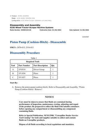
- 1. Product: WHEEL SCRAPER Model: 623G WHEEL SCRAPER CEW Configuration: 623G Wheel Scraper CEW00001-UP (MACHINE) Disassembly and Assembly 623G Wheel Tractor-Scraper Machine Systems Media Number -RENR4249-00 Publication Date -01/06/2004 Date Updated -21/06/2004 i02509987 Piston Pump (Cushion-Hitch) - Disassemble SMCS - 5070-015; 5316-015 Disassembly Procedure Table 1 Required Tools Tool Part Number Part Description Qty A 1P-0510 Driver Group 1 B 1P-1854 Pliers 1 C 1P-1857 Pliers 1 Start By: A. Remove the piston pump (cushion-hitch). Refer to Disassembly and Assembly, "Piston Pump (Cushion-Hitch) - Remove". NOTICE Care must be taken to ensure that fluids are contained during performance of inspection, maintenance, testing, adjusting and repair of the product. Be prepared to collect the fluid with suitable containers before opening any compartment or disassembling any component containing fluids. Refer to Special Publication, NENG2500, "Caterpillar Dealer Service Tool Catalog" for tools and supplies suitable to collect and contain fluids on Caterpillar products. Dispose of all fluids according to local regulations and mandates. 1/12(W) w 2021/4/20 https://127.0.0.1/sisweb/sisweb/techdoc/techdoc_print_page.jsp?returnurl=/sisweb/sisw...
- 2. 1. Apply alignment marks on all mating components for assembly purposes. Illustration 1 g01071362 2. Remove bolts (1) and valve (2) . Illustration 2 g01071364 3. Remove O-ring seals (3) and screw (4A) . 2/12(W) w 2021/4/20 https://127.0.0.1/sisweb/sisweb/techdoc/techdoc_print_page.jsp?returnurl=/sisweb/sisw...
- 3. Illustration 3 g01071365 Personal injury can result from being struck by parts propelled by a released spring force. Make sure to wear all necessary protective equipment. Follow the recommended procedure and use all recommended tooling to release the spring force. 4. Remove plug (11) and O-ring seal (12) . 5. Remove seat (10) , spring (9) , spring (8) , retainer (7) , and spool (6) . 6. Remove plug (19) and O-ring seal (20) . 7. Remove spring (18) , spring (17) , retainer (16) , and spool (15) . 8. Remove plug (4) , washer (5) , plug (13) , and washer (14) from housing (2) . 3/12(W) w 2021/4/20 https://127.0.0.1/sisweb/sisweb/techdoc/techdoc_print_page.jsp?returnurl=/sisweb/sisw...
- 4. Illustration 4 g01071417 Personal injury can result from being struck by parts propelled by a released spring force. Make sure to wear all necessary protective equipment. Follow the recommended procedure and use all recommended tooling to release the spring force. Note: Pump head (22) is under spring tension. Remove bolts (21) slowly. 9. Carefully remove bolts (21) that secure pump head (22) to the pump assembly. Illustration 5 g01071418 10. Remove pump head (22) , plate (23) , piston (24) , plunger (25) , and spring (26) as a unit from pump housing (27) . 4/12(W) w 2021/4/20 https://127.0.0.1/sisweb/sisweb/techdoc/techdoc_print_page.jsp?returnurl=/sisweb/sisw...
- 5. Illustration 6 g01071419 11. Remove plunger (25) , spring (26) , four O-ring seals (28) , piston (24) , and plate (23) from pump head (22) . Illustration 7 g01071420 12. Plate (23) has been turned over by 180 degrees. Note the location of Slot (X) that is in plate (23) for assembly purposes. Slot (X) will be positioned over locating pin (29) when plate (23) is installed to the pump head. Illustration 8 g01071422 13. Plunger guide (30) and piston guide (32) will not be removed from the head. If either cylinder (30) or guide (32) are damaged pump head (22) must be replaced. Remove pin (29) from pump head (22) . Use a suitable heel bar and remove bearing cup (31) from pump head (22) . 5/12(W) w 2021/4/20 https://127.0.0.1/sisweb/sisweb/techdoc/techdoc_print_page.jsp?returnurl=/sisweb/sisw...
- 6. Illustration 9 g01071423 14. Remove plugs (33) from pump head (22) . Remove the O-ring seals from plugs (33) . Illustration 10 g01071425 15. Remove bearing cone (34) and shim (35) from shaft (37) . Remove O-ring seal (36) from pump housing (27) . Illustration 11 g01256552 6/12(W) w 2021/4/20 https://127.0.0.1/sisweb/sisweb/techdoc/techdoc_print_page.jsp?returnurl=/sisweb/sisw...
- 7. 16. Turn the pump housing over 180 degrees and hold the components in the pump housing. Remove pump housing (27) from bearing cone (38) , shaft (37) , swashplate (39) , and rotating group (40) . Illustration 12 g01071427 17. Remove shaft (37) and bearing cone (38) from swashplate (39) and rotating group (40) . Illustration 13 g01071428 18. Use Tooling (A) and a suitable press in order to remove shaft (37) from bearing cone (38) . 7/12(W) w 2021/4/20 https://127.0.0.1/sisweb/sisweb/techdoc/techdoc_print_page.jsp?returnurl=/sisweb/sisw...
- 8. Illustration 14 g01071429 19. Remove swashplate (39) from rotating group (40) . Illustration 15 g01071451 20. Apply identification marks to retraction plate (41) , pistons (42) , and barrel (43) for assembly purposes. The pistons must be installed in the original location in retraction plate (41) and in barrel (43) . All three components must be assembled to the original alignment. Illustration 16 g01071452 8/12(W) w 2021/4/20 https://127.0.0.1/sisweb/sisweb/techdoc/techdoc_print_page.jsp?returnurl=/sisweb/sisw...
- 9. 21. Remove collar bearing (45) from pins (44) and barrel (43) . Illustration 17 g01071453 Personal injury can result from being struck by parts propelled by a released spring force. Make sure to wear all necessary protective equipment. Follow the recommended procedure and use all recommended tooling to release the spring force. 22. Place barrel (43) in a suitable press. Use Tooling (A) in order to depress the spring that is in barrel (43) . Use Tooling (B) in order to remove retaining ring (46) that secures the spring in barrel (43) . Slowly release the pressure from the spring and remove Tooling (A) from the assembly. 9/12(W) w 2021/4/20 https://127.0.0.1/sisweb/sisweb/techdoc/techdoc_print_page.jsp?returnurl=/sisweb/sisw...
- 10. Illustration 18 g01071454 Illustration 19 g01071455 23. Remove retaining ring (46) and spring (47) from barrel (43) . 24. Remove seat (48) that was under spring (47) from barrel (43) . Remove pins (44) from barrel (43) . Illustration 20 g01071456 25. Remove brass bearings (49) from pump housing (27) . 10/12(W) w 2021/4/20 https://127.0.0.1/sisweb/sisweb/techdoc/techdoc_print_page.jsp?returnurl=/sisweb/sisw...
- 11. Illustration 21 g01071457 26. Use Tooling (C) in order to remove retaining ring (50) from pump housing (27) . Illustration 22 g01071458 Illustration 23 g01071459 11/12(W) w 2021/4/20 https://127.0.0.1/sisweb/sisweb/techdoc/techdoc_print_page.jsp?returnurl=/sisweb/sisw...
- 12. Illustration 24 g01071461 27. Lip seal (51) and bearing cup (52) will be removed from pump housing (27) together. 28. Use Tooling (A) in order to remove lip seal (51) and bearing cup (52) from pump housing (27) . 12/12(W) w 2021/4/20 https://127.0.0.1/sisweb/sisweb/techdoc/techdoc_print_page.jsp?returnurl=/sisweb/sisw...
- 13. Product: WHEEL SCRAPER Model: 623G WHEEL SCRAPER CEW Configuration: 623G Wheel Scraper CEW00001-UP (MACHINE) Disassembly and Assembly 623G Wheel Tractor-Scraper Machine Systems Media Number -RENR4249-00 Publication Date -01/06/2004 Date Updated -21/06/2004 i03538320 Piston Pump (Cushion-Hitch) - Assemble SMCS - 5070-016; 5316-016 Assembly Procedure Table 1 Required Tools Tool Part Number Part Description Qty A 1P-0510 Driver Group 1 B 1P-1854 Pliers 1 C 1P-1857 Pliers 1 D 8T-5096 Dial Indicator Gp 1 E 5N-5561 Silicone Lubricant 1 F 9S-3263 Thread Lock Compound 1 Note: Cleanliness is an important factor. Before assembly, all parts should be thoroughly cleaned in cleaning fluid. Allow the parts to air dry. Wiping cloths or rags should not be used to dry parts. Lint may be deposited on the parts which may cause later trouble. Inspect all parts. If any parts are worn or damaged, use new Caterpillar parts for replacement. Note: Apply a light film of 10W oil to all components before assembly. 1/15(W) w 2021/4/20 https://127.0.0.1/sisweb/sisweb/techdoc/techdoc_print_page.jsp?returnurl=/sisweb/sisw...
- 14. Illustration 1 g01071755 1. Use Tooling (C) in order to install retaining ring (50) to pump housing (27) . Illustration 2 g01071756 2. Use Tooling (A) in order to install lip seal (51) to the pump housing. The sealing lip of the lip seal should face toward the bearing cup. The lip seal must seat against the retaining ring. Illustration 3 g01071757 2/15(W) w 2021/4/20 https://127.0.0.1/sisweb/sisweb/techdoc/techdoc_print_page.jsp?returnurl=/sisweb/sisw...
- 15. 3. Lower the temperature of bearing cup (52) . Use Tooling (A) in order to install bearing cup (52) to pump housing (27) . Install bearing cup (52) until the bearing cup seats. 4. Use the following steps to determine the preload on the bearings of the pump assembly. Illustration 4 g01071758 a. Lower the temperature of shaft (37) . Use a suitable press in order to install shaft (37) into bearing cone (38) . Install shaft (37) until bearing cone (38) is seated onto shaft (37) . Illustration 5 g01071773 b. Install shaft (37) into pump housing (27) . 3/15(W) w 2021/4/20 https://127.0.0.1/sisweb/sisweb/techdoc/techdoc_print_page.jsp?returnurl=/sisweb/sisw...
- 16. Illustration 6 g01071774 c. Install shim (35) and bearing cone (34) on pump shaft (37) . Illustration 7 g01071775 d. Lower the temperature of bearing cup (31) . Use Tooling (A) and a suitable press in order to install bearing cup (31) in pump head (22) . Install the bearing cup until the cup is seated. Illustration 8 g01071776 4/15(W) w 2021/4/20 https://127.0.0.1/sisweb/sisweb/techdoc/techdoc_print_page.jsp?returnurl=/sisweb/sisw...
- 17. Illustration 9 g01071778 e. Position pump head (22) onto pump housing (27) . Install bolts (21) but do not tighten bolts (21) at this point. f. Use a feeler gauge to measure the distance between the pump head and the pump housing. Take measurements at three equal locations on the surface between the pump head and the pump housing. g. The average of the three dimension should be zero to 0.050 mm (0.0020 inch). h. If the dimension is not correct remove shim (35) . Refer to Illustration 6. To achieve the correct dimension, grind the shim or replace shim (35) . i. When the correct dimension is achieved tighten bolts (21) and then invert the pump assembly. j. Use Tooling (D) , a suitable screwdriver, and a set of slip joint pliers to check the end play on shaft (37) . If end play exists on the shaft, repeat Step 4 until the correct dimension is reached. k. Remove bolts (21) and pump head (22) from pump housing (27) . Remove bearing cone (34) and shim (35) from shaft (37) . Remove shaft (37) . l. Proceed with the assembly of the piston pump. 5/15(W) w 2021/4/20 https://127.0.0.1/sisweb/sisweb/techdoc/techdoc_print_page.jsp?returnurl=/sisweb/sisw...
- 18. Illustration 10 g01071456 5. Install brass bearings (49) into pump housing (27) . Illustration 11 g01071779 6. Install pins (44) into barrel (43) . Illustration 12 g01071455 7. Install seat (48) in order to secure pins (44) in barrel (43) . 6/15(W) w 2021/4/20 https://127.0.0.1/sisweb/sisweb/techdoc/techdoc_print_page.jsp?returnurl=/sisweb/sisw...
- 19. Illustration 13 g01071454 8. Position barrel (43) in a suitable press. Install spring (47) in barrel (43) . Position retaining ring (46) on top of the spring. Illustration 14 g01071453 Improper assembly of parts that are spring loaded can cause bodily injury. To prevent possible injury, follow the established assembly procedure and wear protective equipment. 9. Position Tooling (A) and the suitable press on top of the spring and inside of retaining ring (46) . Use Tooling (A) in order to depress the spring that is in barrel (43) . Use Tooling (B) in order to install retaining ring (46) that secures the spring in barrel (43) . Remove Tooling (A) . 7/15(W) w 2021/4/20 https://127.0.0.1/sisweb/sisweb/techdoc/techdoc_print_page.jsp?returnurl=/sisweb/sisw...
- 20. Illustration 15 g01071452 10. Install collar bearing (45) to pins (44) and barrel (43) . Illustration 16 g01071451 11. Install pistons (42) to the original positions in retraction plate (41) . Install pistons (42) and retraction plate (41) to barrel (43) . Pistons (42) must be installed to the original positions. Illustration 17 g01071429 8/15(W) w 2021/4/20 https://127.0.0.1/sisweb/sisweb/techdoc/techdoc_print_page.jsp?returnurl=/sisweb/sisw...
- 21. 12. Position swashplate (39) to rotating group (40) . Illustration 18 g01071427 13. Install shaft (37) and bearing cone (38) to swashplate (39) and rotating group (40) . 14. Apply clean hydraulic oil to the components of the pump. Illustration 19 g01071426 15. Install pump housing (27) to bearing cone (38) , swashplate (39) , and rotating group (40) . Turn the pump body over 180 degrees and hold the components in the pump body. 9/15(W) w 2021/4/20 https://127.0.0.1/sisweb/sisweb/techdoc/techdoc_print_page.jsp?returnurl=/sisweb/sisw...
- 22. Illustration 20 g01071780 16. Position pump housing (27) on suitable cribbing. Position shaft (37) between the two blocks of wood. 17. Install bearing cone (34) and shim (35) to shaft (37) . Apply clean hydraulic oil to the bearing cone. Install O-ring seal (36) to pump housing (27) . 18. Apply Tooling (E) onto plunger (25) . Illustration 21 g01087607 19. Position plunger (25) to the wear pad that is positioned on the swashplate. Tooling (E) will hold plunger (25) in place. Install spring (26) on plunger (25) . 10/15(W) w 2021/4/20 https://127.0.0.1/sisweb/sisweb/techdoc/techdoc_print_page.jsp?returnurl=/sisweb/sisw...
- 23. Illustration 22 g01071783 20. Install the O-ring seals to plugs (33) . Install plugs (33) to pump head (22) . Tighten the plugs to a torque of 45 ± 5 N·m (33 ± 4 lb ft). Illustration 23 g01071784 21. Install locating pin (29) to pump head (22) . Apply Tooling (F) onto the threads on piston guide (30) and plunger guide (32) . Install the piston guide and plunger guide into pump head (22) and tighten to a torque of 80 N·m (60 lb ft). Apply Tooling (E) onto guide (32) . 11/15(W) w 2021/4/20 https://127.0.0.1/sisweb/sisweb/techdoc/techdoc_print_page.jsp?returnurl=/sisweb/sisw...
- 24. Illustration 24 g01071420 22. Apply Tooling (E) onto the side of plate (23) that has Slot (X) . Slot (X) will be positioned over locating pin (29) when plate (23) is installed to the pump head. Illustration 25 g01071785 23. Install plate (23) to pump head (22) . Install four O-ring seals (28) to pump head (22) . Apply Tooling (E) onto piston (24) . Install piston (24) to guide (32) . Illustration 26 g01071786 Improper assembly of parts that are spring loaded can cause bodily injury. To prevent possible injury, follow the established assembly procedure and wear protective equipment. 12/15(W) w 2021/4/20 https://127.0.0.1/sisweb/sisweb/techdoc/techdoc_print_page.jsp?returnurl=/sisweb/sisw...
- 25. 24. Install pump head (22) , plate (23) , piston (24) , plunger (25) , and spring (26) as a unit to pump housing (27) . Remember to align the marks that were applied to the mating components. 25. Use two people in order to maneuver plunger (25) into spring (26) . Position piston (24) to the wear pad that is positioned on the swashplate. Tooling (E) will hold the piston in place. 26. When all of the components are aligned, pump head (22) should be positioned to pump housing (27) . Illustration 27 g01071417 Improper assembly of parts that are spring loaded can cause bodily injury. To prevent possible injury, follow the established assembly procedure and wear protective equipment. 27. Install bolts (21) that secure pump head (22) to the pump assembly. The head is under spring tension. Install the bolts slowly. Tighten bolts (21) to a torque of 21 ± 5 N·m (16 ± 4 lb ft). 13/15(W) w 2021/4/20 https://127.0.0.1/sisweb/sisweb/techdoc/techdoc_print_page.jsp?returnurl=/sisweb/sisw...
- 26. Illustration 28 g01071365 28. Install washer (5) and plug (4) into housing (2) . 29. Install washer (14) and plug (13) into housing (2) . 30. Install spool (6) , retainer (7) , spring (8) , spring (9) , and seat (10) . 31. Install O-ring seal (12) and plug (11) . 32. Install spool (15) , retainer (16) , spring (17) , and spring (18) . 33. Install plug (19) and O-ring seal (20) . Illustration 29 g01071364 34. Install O-ring seals (3) and screw (4A) . 14/15(W) w 2021/4/20 https://127.0.0.1/sisweb/sisweb/techdoc/techdoc_print_page.jsp?returnurl=/sisweb/sisw...
- 27. Suggest: If the above button click is invalid. Please download this document first, and then click the above link to download the complete manual. Thank you so much for reading
- 28. Illustration 30 g01071362 35. Install valve (2) and bolts (1) . 36. Fill the pump with hydraulic oil before installing the pump to the machine. End By: Install the piston pump (cushion-hitch). Refer to Disassembly and Assembly, "Piston Pump (Cushion-Hitch) - Install". 15/15(W) w 2021/4/20 https://127.0.0.1/sisweb/sisweb/techdoc/techdoc_print_page.jsp?returnurl=/sisweb/sisw...