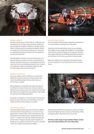
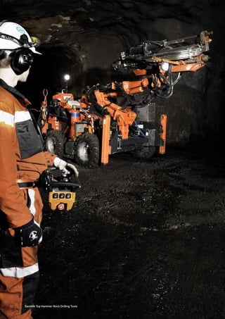
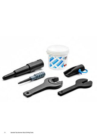
SANDVIK TOP HAMMER
ROCK DRILLING TOOLS
2 Sandvik Top Hammer Rock Drilling Tools
IT’S ALL ABOUT EVERYONE’S HEALTH
Helping you to ensure a safer workplace and healthier
­workforce is of the utmost importance to us. The well­
being of any person coming into contact with our equip-
ment is paramount. Therefore, we strive to identify and
assess potential risk factors that could threaten the
health of you and your employees.
All of the products in this catalogue are designed to meet
safety requirements.
BE AWARE OF ALL SAFETY PROCEDURES
We ask that you start by obeying all instructions given.
Never work under an unsupported roof or close to potential
pinch point locations. Beware of the potential hazards of
a loose roof and ribs, and scale down roof and ribs prior
to bolting. It is important to bolt early in the mining process
– as soon as is safely and practically possible.
Safe work procedures should incorporate inspection
­before the machine operates, and also through regular
monitoring based upon mining conditions, safety and
hazard­management systems. Workers should be provided
with safety information, instruction and training on trans-
portation, installation, operational care and disposal
of drilling tools.
The mining industry continues to demand even higher levels of safety and productivity.
In order to meet these requirements, we work continuously to develop even safer
­products, and to produce comprehensive manuals on the safe and effective use
of our products.
DRESS RIGHT FROM HEAD TO TOE
You must wear appropriate personal protective
­equipment (PPE) at all times. This is what we strongly
­recommend, to help avoid injury:
–– Safety helmet
–– Hearing protection
–– Safety glasses
–– Protective high visibility clothing
–– Respiratory protection
–– Safety boots
–– Any site-specific PPE as required
MAKE A RISK ANALYSIS BEFORE YOU START
Pay attention to safety when planning all of your work.
Before you start, always take your time to go through all
operations. Identify any potential risks and take appropriate
measures to avoid them. If necessary, seek expert advice
on how to help minimize risks. Finally, make sure that you
have the right resources to perform all tasks in the safest
manner possible.
PUTTING YOUR
SAFETY FIRST
“TAKE FIVE” TO IDENTIFY HAZARDS
A great safety tool to use before you start working is our app:
“Sandvik Mining Take Five”. The app consists of a simple, step-
by-step checklist with five questions that you should ask yourself
to identify potential hazards. The app is free to download for smart-
phones and tablets, both on the App Store and Google Play.
3Sandvik Top Hammer Rock Drilling Tools
4 Sandvik Top Hammer Rock Drilling Tools
LIFTING PROCEDURES
Use the correct safe lifting practices while working
with heavy items. Consider your body position, the
­awkwardness of the item and its weight. Are two people
required for the job, or is a lifting device necessary?
GRINDING OF BITS
Drill bits have cemented carbide buttons. Cemented
­carbide is made up of tungsten carbide and cobalt.
Grinding buttons can produce dust and fumes containing
dangerous substances that can be inhaled or swallowed,
or which can come in contact with the skin or eyes. Do
not breathe the dust. Wear protective gloves/protective
clothing/eye protection. In case of inadequate ventilation,
wear respiratory protection. In particular, avoid dry grinding.
For more information see page 115.
ASSEMBLY OF BITS
–– Do not touch any equipment while it is rotating.
–– Rod rotation must be stopped before the installation
or removal of a drill bit.
–– Follow site instructions for the isolation of rotation
­motors.
–– Beware of pinch points between the bit and the rod.
DRILLING WITH HANDHELD EQUIPMENT
Sandvik rock tools are designed and manufactured
to the highest standards. A specific hazard exists with
handheld drilling equipment, where if the drill rod breaks
it can form an impalement hazard (if the broken drill steel
protrudes from the hole it was drilling, while the driller
is pushing towards it).
HOW TO WORK
WITH SAFETY IN MIND
5Sandvik Top Hammer Rock Drilling Tools
DISASSEMBLY OF HOT BIT, ROD, COUPLING,
SLEEVE, SHANK­ADAPTER AND INTERGRAL STEEL
–– Ensure that products have cooled down before
­disassembling.
–– Never work on hot parts.
–– Consider the appropriate hand protection (gloves)
for the handling of warm parts.
CLEANING OF RODS
A particular hazard exists with cleaning rods if the rods
contain explosives. Sandvik rock tools should never
be used in a hole that has been filled with explosives.
DEALING WITH WORN PARTS
Worn parts should be removed and disposed of appro-
priately. Consider recycling any used drill bits. Please
contact your local Sandvik Mining representative for
­support and further information regarding the recycling
process.
STORING
All products should be stored in a dry place and in their
original packaging until they are required for use.
GENERAL
The products in this catalog are designed for drilling
holes in rock, and should only be used for this purpose.
6 Sandvik Top Hammer Rock Drilling Tools
Sandvik was founded in 1862 by Göran Fredrik Göransson, who was the first in the world to succeed in using
the Bessemer method for steel production on an industrial scale.
TOGETHER WE WILL TAKE
YOUR BUSINESS FURTHER
For more than 150 years we have been committed to
providing the highest-quality products and solutions to
the mining industry. Our spirit and business ethics have
remained unchanged, and developments within society
and the industry have contributed to our innovative
­solutions.
Today, we continue to conduct business in close
­cooperation with you and other customers all over
the world, with the promise of being a proactive
and innovative partner.
We believe that we can make a difference to the
­successful running of your business. You need to get
the best out of your equipment - with no compromise
on quality, delivery time or service. With us as partners,
we will create solutions that make your operation run
as effectively as possible.
One thing is certain: our products and solutions will
­continue to meet the ever-growing needs of the mining
industry, and your business.
“Today, the hallmark of great work
is innovation and technology. Being
second best is not an option for us.”
7Sandvik Top Hammer Rock Drilling Tools
CONTENTS
HANDHELD AND SMALL HOLE DRILLING 23
FACEDRILLING AND BOLTING 37
BENCH DRILLING 53
LONG HOLE DRILLING 67
SHANK ADAPTERS 81
AUXILIARY TOOLS 97
GRINDING EQUIPMENT 101
INFORMATION AND BIT CLASSIFICATION GUIDE 117
INDEX	 122
NOTES127
8 Sandvik Top Hammer Rock Drilling Tools
THE SANDVIK GROUP
Sandvik was established in 1862: today, it is a global
­industrial group with advanced products and world-leading
positions in selected areas. In 2013, we had about
47,000 employees and sales of just over 87 billion SEK
in more than 130 countries. Our operations are based on
unique expertise in materials technology, and significant
insight into customer processes. This combination
has provided us with a world-leading position in three
­primary areas:
–– Tools for metal cutting in cemented carbide and
­high-speed steel, as well as components in cemented
carbide and other hard materials.
–– Rock tools and equipment for the mining and
­construction industries.
–– Products in advanced stainless materials, special
­alloys, metallic and ceramic resistance materials
and process systems.
Our goal is to actively contribute to improving your
­productivity and, consequently, your profitability. Our
products and services provide maximum value to you
in terms of performance, quality, speed, safety, flexibility
and – not least – total economy. Successful development
is a result of our goal-oriented investment in research,
AT YOUR SERVICE,
AROUND THE WORLD
“We are a leading global supplier
of rock tools and equipment, service
and technical solutions for the mining
industry. Our offering covers rock
drilling, rock cutting, rock crushing,
loading and hauling, and handling
of materials.”
development and quality assurance. We invest over
3 billion SEK annually and have more than 2,700 employees
working in these areas. Many of them are specialists with
advanced educational backgrounds and skills.
Our long-term and consistent strategy is based on the
­interaction between a number of strength factors. This
­includes advanced and customer focused research and
development activities, highly value-added products,
­integrated manufacturing, direct sales to customers,
­effective logistics systems, financial strength and a
strong corporate culture. Additionally, the significance
of Sandvik as an advanced knowledge company is
­becoming ­increasingly apparent. Information technology
is concentrated upon areas that enhance customer
­benefits, ­improve productivity and strengthen
­profitability.
SANDVIK MINING
We are a leading global supplier of rock tools and
­equipment, service, and technical solutions for the mining
industry. Our offering covers rock drilling, rock cutting,
rock crushing, loading and hauling and handling of mate-
rials. Additionally, we offer a complete assortment of rock
drilling tools. In fact, we are the only producer of rock
drilling tools with in-house steel and cemented carbide
research, development and production facilities.
OUR ORGANIZATION
Every product is preceded by extensive research and
­development, and backed with application expertise;
a worldwide service network, offering on-site service,
training and round-the-clock support. We have a tradition
of localization and a conviction that there can be no
­substitute for direct service and direct contact with you.
Our service-oriented, global organization is well devel-
oped and contains more than 3,500 service technicians
located strategically around the world.
9Sandvik Top Hammer Rock Drilling Tools
Our worldwide business activities are conducted via representation in more than 130 countries.
10 Sandvik Top Hammer Rock Drilling Tools
11Sandvik Top Hammer Rock Drilling Tools
Through close customer collaboration, we develop
­products that are genuinely needed. We also study
trends to ascertain what customer needs will be in the
future. We are continuously working on unique solutions
that help our customers to improve their productivity
and safety.
WHICH INVENTION CAN
SOLVE YOUR NEEDS?
Our focus and continuous development gives you the
latest technical solutions for the most demanding rock
conditions, and for the most powerful rock tools. Our
products undergo extensive laboratory studies and are
mercilessly tested in the field. Finally, they are all evaluated
and refined to provide the highest grade of equipment
quality - something that characterizes all our products.
“The spirit of innovation and
involvement runs through every
product.”
We invest over 3 billion SEK each year in research and development: more than 2,700
of our employees are employed in this area. We have 8,000 active patents.
A spirit of innovation and high involvement runs through
every product. It is preceded by our extensive research
and development. This is supported by a worldwide
­service network offering on-site service, training and
round-the-clock support. We have technical service
specialists strategically located around the world
to provide help quickly – whenever you need it.
12 Sandvik Top Hammer Rock Drilling Tools
RECYCLING THAT
PAYS OFF FOR YOU
Environmental considerations are crucial in all of
our operations, and never more so than when it comes
to the recycling of cemented carbide.
The global shortage of raw material has inspired us
to create an extensive scrap-recycling program. We
­recognize today’s increasing environmental concerns,
and we are the only mining company that recycles both
steel and cemented carbide.
In fact, we have been collecting and recycling both
scrap and discarded drilling consumables for conversion
back into basic raw materials for almost 10 years. A large
number of customers have joined our recycling program
during this period. One major reason for this is that we
make it easy for them to recycle, by collecting scrap
from their own premises.
All of our customer service centres are now set up to
­receive used cemented carbide-enhanced products.
Our recycling plant in Chiplun, India complies with the
most stringent environmental standards, and is certified
to the ISO 14001 and OHSAS 18001 (ISO 45001)
­international standard.
WHAT WE OFFER:
–– Recycling of cemented carbide for customers
­worldwide
–– Genuine recycling
–– Cost recovery and reduced waste disposal for you
–– Money received for worn tools can purchase new
­inserts or finance new tooling projects
–– Consumables and tools from all manufacturers
are accepted
–– A win-win situation for all
Adopting sustainable business practices and handling
them in the right way is a foundation that contributes
across the entire business value chain.
The whole supply chain will be improved by incorporating
recycling into the business process. For instance, our
­recycling process significantly reduces energy con-
sumption to increase productivity, enhance business
oppor­tunities and cause less environmental damage.
13Sandvik Top Hammer Rock Drilling Tools
NEW GENERATION OF CEMENTED CARBIDE
We develop our own production processes. This
strengthens our technical capabilities to continually
­create even sharper tools that give you the strength
to successfully master the toughest of challenges.
Research, development and production of key materials,
such as cemented carbide, is an important part of our
business.
An extensive programme of research has resulted
in a new generation of carbide grades. These have
a significantly stronger carbide matrix, and a perfect
grain size configuration: meaning superior toughness
and a high wear temperature resistance.
THE TOUGH GRADE XT48 BIT 
Through our new manufacturing techniques, we have
created the new XT48 cemented carbide – just one
­example of our new generations of cemented carbide
grades. The XT48 has increased density and a more
­homogenous structure. Consequently, it has led to the
development of larger, stronger, and more stable and
­efficient tools.
Some characteristics of the XT48 BIT:
–– Optimized cutting structure
–– Ballistic or super spherical buttons
–– Deep flushing grooves, with optimal positioning
–– Optimized wing/head design
The gauge buttons of a drill bit are
exposed to axial forces. Our former
cemented carbides have always
been able to handle that type of
load with minimal risk of breakage.
When the bit wears, the load angle
changes and the risk for button
breakage increases. The new XT48
cemented carbide displays signifi-
cantly higher levels of resistance
to that type of failure.
Our rolling mill for hollow drill steel is the most up- to-date
in the world. The unique, fully automated mill is specially
designed for manufacturing of this steel product. After
rolling, the rods are turned to avoid decarburisation in the
final rolling process. A long, straight centre hole is drilled
GIVING
YOU
STRENGTH
in the drill steel blank and a core is inserted. The blanks
are hot-rolled into a round or hexagon-shape. Finally,
a carefully controlled cooling process after rolling
­guarantees uniform mechanical properties. The core
is then removed and the drill steel is ready for shipping.
OWN, UNIQUE STEEL PRODUCTION
14 Sandvik Top Hammer Rock Drilling Tools
SIX MAIN BENEFITS OF THE GT60:
1.
The steel in Sandvik GT60 rods is produced in one
of the world’s most advanced continuous casting plants.
Almost 90 years of experience in rolling hollow bar steel
means that we are uniquely able to produce steel with
close tolerances and excellent material properties.
2.
The Sandvik GT60 system includes Sandvik button bits,
to comply with all kinds of rock formations and drilling
site conditions.
3.
The Sandvik GT60 system provides double the penetration
rate and consumes half the energy of DTH drilling.
4.
The Ø 60 mm rod cross-section is optimized for the high
energy transfer of impact power in top hammer drilling
of Ø 92 to 152 mm holes. Compared with 51 mm rods,
the 40 % larger cross-section and 65% higher bending
stiffness permit faster penetration rates and straighter
holes.
5.
Sandvik GT60 is perfectly suited to automatic rod
­handling systems. Male and female (MF) threads mini-
mize energy losses and simplify handling.
6.
Large flushing holes provide superior removal of cuttings
and improve drilling performance. The exact centering
of the hole during manufacture ensures uniform steel
walls and consistent product performance.
DRILL BITS THAT CAN
HANDLE ANY SITUATION
The Sandvik GT60 bits are created in our unique engineering and manufacturing
facility. As a result of this, we can tailor the characteristics of the bits to match almost
any drilling conditions that we might face.
15Sandvik Top Hammer Rock Drilling Tools
LESS
HANDLING,
MORE WORK
HIGHER PRODUCTIVITY
Each +Range rod offers more meters drilled. Fewer
rod changes ensures more time for drilling and less time
spent replacing. The increased equipment utilization
­results in improved uptime of the drill rig, while reducing
the overall cost of your drilling operation per blast hole.
SUBSTANTIAL COST SAVINGS
An extended service life of 30% or more provides
you with a lower cost per meter drilled. Since each drill
rod offers more meters of use, fewer rods need to be
kept in stock – and since fewer rods need to be handled,
the associated cost is also reduced.
REDUCED ENVIRONMENTAL IMPACT
Each rod’s longer service life allows you to drill more per
kilo of steel. Carbon footprints decrease from rock drill
steel production to shipping and transportation on site,
as well as after use. There is also a reduction in the total
number of kilos of steel that need to be recycled.
+RANGE ON LOCATION
Customer: High Point Opencast Mining Service
Country: South Africa
Previous solution: Sandvik GT60 standard
New solution: Sandvik GT60+
Results: High Point averages between 30 and 35 percent more service life with the new rods,
­resulting in a production increase of 10 to 15 percent.
Quote: “When we tested the GT60+ rods, we put the new ones on one machine and the old
type on another machine. They were drilling next to each other so we could compare apples
with apples, and that’s how we discovered that with some of the best rods we got 13,800 metres
out of the new GT60+ rods. That’s more than double the average.”
– Johan Coetzee, managing director of High Point Opencast Mining Service
Customer: Diesel Power Opencast Mining
Country: South Africa
Previous solution: Sandvik GT60 standard
New solution: Sandvik GT60+
Results: In two months of testing the new rods, Diesel Power has achieved major fuel savings,
among other benefits, improving the contractor’s carbon footprint.
Quote: “We haven’t had breakages, and we have better threads. When we started using the
+Range, our meters picked up. On a GT60+ drill rod we achieved as much as 24,907 metres.
We drilled on a whole string of drill steel for that month.”
– Erick Walker, senior drill and blast foreman at Diesel Power
16 Sandvik Top Hammer Rock Drilling Tools
CARBURISATION
–– Case hardening in a furnace with carbon rich gas
–– Increased carbon content in the outer layer hardens material
INDUCTION SURFACE HARDENING (HF) + THREADS
–– Hard, wear-resistant surface
–– Improved fatigue strength
–– Induction hardening of threads
–– Rapidly heated and cooled
PROCESSES
INVOLVED IN MAKING
RODS
SANDVIK ALPHA FEATURES AN ENTIRELY
NEW THREAD DESIGN
The benefits of short threads on hexagonal drill rods
­include superior resistance to bending stresses, improved
bit guidance and outstanding energy transfer. The sturdy
thread is well supported inside the bit skirt, resulting
in high precision collaring – even in complex rock
­formations and against uneven surfaces.
MF-DESIGN GIVES STRAIGHTER HOLES
Male-Female (MF) drill rods provide a more rigid drill string
than ones which use extension rods and couplings.
This is due to a 50 % reduction in thread play of the MF
rod connections vs. coupling connections. Drilling with
a stiffer drill string results in improved hole straightness,
improved efficiency, and improved safety.
17Sandvik Top Hammer Rock Drilling Tools
Great versatility, higher penetration rates, straighter
holes, longer bit life and lower energy consumption.
That’s what you can expect from the Sandvik bits: an
­exceptionally versatile series of threaded button-bits
ranging from 28 to 152 mm in diameter. The buttons
are made from proprietary grades of cemented carbide:
Sandvik supplies all of the most useful and effective ­button
shapes (spherical, conical or ballistic) and the required
skirt designs (regular or retrac) in order to obtain the
best bit for the rock formation in question.
HIGHER PENETRATION RATES,
LOWER ENERGY CONSUMPTION
“If button failure is a problem
in your rock formation, then you
are certain to see an increase
in bit life with Sandvik rock tools.”
TWICE AS LONG
SERVICE LIFE
The management at an Australian mine welcomed
the news of higher productivity and lower costs. Sandvik
Alpha drill bits give almost double the service life com-
pared to drill bits used previously, which were notorious
for button breakages. In a large-scale test, stoppages
were down and productivity up: meanwhile, bit costs
were cut by half.
IMPROVED
PERFORMANCE
In tests, Sandvik Alpha bits exceeded the mine average
by 25% in Canada. This figure includes bit damage during
uncoupling, but after corrections in procedures the bit
performed at more than 50 % above the mine’s average
when used on very hard and abrasive rock. The new bits
could also be reground 5–7 times, compared to 3– 4 as
with the old standard.
Drifter bit service life was proven to be at least 20%
higher than competition in a Swedish mine.
18 Sandvik Top Hammer Rock Drilling Tools
LUBRICATION
Thread grease reduces wear and helps in the uncoupling
of rods. Replace the lid on the grease container after use.
The grease must be protected from drilling dust, as left
unprotected it will interact with this substance – and act
as grinding compound instead of lubrication the next
time it is used.
THREAD WEAR
Drilling with worn threads carries a great risk of equipment
downtime. When replacing drill rods, it is often more eco-
nomical to replace the coupling as well. Mixing new and
old threads can make the newer ones wear more quickly.
BENT AND BLOCKED DRILL STEELS
Not all bent drill steels have to be discarded. They
can often be straightened, either in the hole or with
a straightening press.
  Drill steels and rods’ flushing holes can become
blocked. Any blockage can normally be removed with
the aid of a copper tube and water.
TRANSPORTATION AND STORAGE
During transportation, bits and cemented components
must be packed so as to prevent damage to the cemented
carbide. Even though cemented carbide is very resistant
to impact against other materials, it is easily damaged
by collision with other components made of the same
material.
PREPARATION AND MAINTENANCE
Good drilling practice and correct machine settings
are important for the service life of your drilling tools.
Management and maintenance also play crucial roles
in an efficient and profitable operation.
HOW TO TAKE CARE
OF YOUR THREADS
19Sandvik Top Hammer Rock Drilling Tools
BUTTON BITS SHOULD BE REGROUND WHEN
PENETRATION RATES DROP, OR IF THE CEMENTED
CARBIDE SHOWS SIGNS OF DAMAGE
Fixed grinding routines bring with them good working
practice. Bits for instance, should be examined and
then reground after a specific number of holes, or at
the end of a shift. Premature grinding is not necessarily
uneconomical, since less carbide needs to be ground
off. It is better to regrind than experience low productivity
due to damage.
The height of the cemented
­carbide diminishes as wear
­progresses, resulting in
it wearing flat.
Wear to the cemented carbide
on the periphery of the bit is
­abnormally high, causing an
“anti-taper” to develop which
­diminishes the clearance
of the bit.
Here, the surface has become
­fatigued and developed micro-
scopic cracks.
Cemented carbide is one of the most successful composite engineering materials
­produced. Its unique combination of strength, hardness and toughness satisfies
the most demanding applications – but working with such high stresses, inserts
and buttons are more subject to wear.
CORRECT ACTIONS KEEP
THE PACE AT ALL TIMES
Proper grinding adds considerably to the service life
of drill bits. Another equally important aspect of proper
grinding is that it also enhances the performance of the
entire drilling operation, particularly hole straightness.
Grinding should always be done in accordance with safety
regulations,: read more about our Health and Safety
­Information on page 115.
20 Sandvik Top Hammer Rock Drilling Tools
TOP HAMMER DRILLS
Renowned for high penetration rates, reliability, fuel
economy and low operating cost, Sandvik top hammer
drills are diesel powered, self-contained and equipped
with air compressors, dust collection systems and oper-
ator’s cabins. They are designed for drilling 22 to 152 mm
(¾ to 6) blastholes up to 30 meters deep.
Sandvik has invested in expanding the top hammer drilling
application, in automation, in environmentally friendly
systems and energy efficiency. The innovation brought
into the market includes AutoMine Surface Drilling,
­automated drilling phases, data sharing, 3D navigation,
i-controls and user interface and training simulation,
to improve competitiveness and profitability.
The DPi range of heavy-duty top hammer rigs drill 89
to 152 mm diamater blastholes. High production rates,
hole quality and drilling economy combine for optimal
performance. The DPi drills are designed to use 51 to
60 mm drill steel, which provide high bending resistance,
enabling the use of maximum kinetic power for drilling
straight holes fast without compromising rock tool
­service life.
The highest performance of the DX range of medium-
heavy top hammer drills refers to power, versatility,
­operator comfort and reliability. The drilling capacity
is boosted by the revolving superstructure, which allows
the operator turn it 120° giving a drilling coverage of
18 m². The drills are stable even in the roughest terrain.
As the cabin turns with the superstructure, the operator
has increased visibility.
HIGH PERFORMING RIGS WITH
LOW OPERATIONAL COSTS
Our drilling equipment is known for its quality, reliability and high productivity. Every
machine we make is designed to give the lowest possible cost per meter drilled and
a low life-cycle cost. We offer an extremely wide choice of machines, ranging from
­robust hydraulically controlled to fully automated units that give extraordinary
­production rates and low total cost.
21Sandvik Top Hammer Rock Drilling Tools
MINING JUMBOS
We offer a wide variety of face drills for smallscale mine
development up to large-scale tunneling. Leading the
way through the toughest conditions, Sandvik jumbos
excel in productivity and outstanding reliability. Safety
and ergonomics have been key elements in ensuring
a comfortable working environment for the operators
and service personnel.
Well-designed, modular structures and proven com­
ponents keep our jumbos running. A combination of
­efficient rock drills, robust booms and advanced controls
meet even the most challenging requirements. Custom-
ers heading for superior excavation quality can also
choose a higher level of instrumentation.
ROCK SUPPORT DRILLS
Our rock support drill rigs make underground excavations
not only productive workplaces but also safer.
Advanced mechanized bolting cycles ensure reliability
and integrity of every single bolt installation. The full bolting
cycle can be conducted safely by one operator. Sandvik
rock support drill rigs can handle all typical bolt dimensions
and any type of commonly used bolts, including cable.
Maximum safety for your operator and productivity are
the main guidelines in the development of the product
family.
LOW PROFILE DRILLS
Improved safety, productivity and minimized ore dilution
are the benefits we also offer you in low reef mining
­applications. Sandvik 200L series drill rigs have been
­designed for low profile mining in working sections as
low as 1.7 meters, with optimum drilling coverage and
­performance. They are typically used in tabular ore
­bodies such as platinum and chrome mines for develop-
ment, rock support and production drilling.
Mechanized low profile mining has been used for a number
of years with great success on various mining sites, clearly
increasing safety and productivity in the mines.
We have a wide range of rigs available. Please contact
your local representation for more information.
PRODUCTION DRILLS
Accuracy makes a world of difference in production
­drilling. Our longhole drill rigs minimize ore loss and
­dilution by drilling straight and accurate holes, up
to 54 meters in length.
We’ve designed a comprehensive range of products
for different mining methods and mining conditions:
­different boom types, carrier size classes and rock drill
with right rock tool selection ensure optimum hole quality
for any long-hole drilling application.
Automation capabilities of the production drill rigs variy
based on your needs, from manual drilling to fan auto­
mation and tele-remote drilling as an option.
22 Sandvik Top Hammer Rock Drilling Tools
23Sandvik Top Hammer Rock Drilling Tools
Integral drill steels, tapered rods, drill
bits and threaded rods are key for high
productivity in all applications. Our drill
steel has a high fatigue strength and tough­
ness, and offers the high wear resistance
that provides an efficient and economic
drilling operation. The unique R23 rods
and bits for extension drilling provide
the strongest thread in sizes ranging
from 33 to 45 mm. For underground appli-
cations, we have fully carburized rods with
superior wear resistance and service life.
When working with us, you can expect
consistently high quality, and maximum
operational dependability when it comes
to all small hole-drilling applications.
H19 (3/4) INTEGRAL DRILL STEELS 24
H22 (7/8) INTEGRAL DRILL STEELS 25
H22 TAPERED TOOLS, 12° TAPER 26
H22 TAPERED TOOLS, 11° TAPER 28
H22 TAPERED TOOLS, 7° TAPER 29
R22 (7/8) EXTENSION DRILLING TOOLS 30
R23 (29/32) EXTENSION DRILLING TOOLS 31
R25 (1) EXTENSION DRILLING TOOLS 32
INCREASE SERVICE LIFE
AND BOOST PRODUCTIVITY
HANDHELD AND SMALL HOLE DRILLING
24 Sandvik Top Hammer Rock Drilling Tools
HANDHELD AND SMALL HOLE DRILLING
H19 (3/4) INTEGRAL DRILL STEELS
DIMENSIONS PART NO.
Series
L
mm ft in
D
mm in
Shank 19×108 mm (3/4×4 1/4)
Hex D-19
L108
Hex D-19
D
21 400 1' 4 29 19/64 724-0429
– 800 2' 7 28 1 7/64 724-0828
– 1600 5' 3 27 1 1/16 724-1627
– 2400 7' 10 26 1 1/32 724-2426
24 600 2' – 27 1 1/16 724-0627
– 1200 3' 11 26 1 1/32 724-1226
Boulder-
steel
400 1' 4 24 15/16 724-0424
800 2' 7 23 29/32 724-0823
Shank 22×108 mm (7/8×4 1/4)
Hex D-19
L108
Hex D-22
D
400 1' 4 24 15/16 728-0424
400 1' 4 29 1 9/64 728-0429
800 2' 7 28 1 7/64 728-0828
1600 5' 3 27 1 1/16 728-1627
BIT DIAMETER NOTES
All bit diameters are larger than the given dimensions
in the catalog
Cross bits:	 Can be a maximum of +1 mm due
to manufacturing tolerance
Button bits:	 Some bit designs can be a maximum
+3 mm to compensate for fast diameter wear.
The minimum diameter for all button bits is +1.5 mm
above the given dimensions
Keep in mind that a bit always gives a bigger hole
than the stated bit diameter.
25Sandvik Top Hammer Rock Drilling Tools
HANDHELDAND
SMALLHOLEDRILLING
FACEDRILLING
ANDBOLTING
BENCHDRILLINGLONGHOLEDRILLINGSHANKADAPTERSAUXILIARYTOOLSGRINDINGEQUIPMENT
INFORMATIONANDBIT
CLASSIFICATIONGUIDE
HANDHELD AND SMALL HOLE DRILLING
H22 (7/8) INTEGRAL DRILL STEELS
DIMENSIONS PART NO.
Series
L
mm ft in
D
mm in
Shank 22×108 mm (7/8×4 1/4)
Hex D-22
L108
Hex D-22
D
11 800 2' 7 34 1 11/32 714-0834-65
1600 5' 3 33 1 19/64 714-1633-65
2400 7' 10 32 1 1/4 714-2432-65
3200 10' 6 31 1 7/32 714-3231
4000 13' 1 30 1 3/16 714-4030
4800 15' 9 29 1 9/64 714-4829
5600 18' 4 28 1 7/64 714-5628-50
6400 21' – 27 1 1/16 714-6427-50
7200 23' 8 26 1 1/32 714-7226-50
12 800 2' 7 40 1 37/64 714-0840-65
1600 5' 3 39 1 17/32 714-1639-65
2400 7' 10 38 1 1/2 714-2438-65
3200 10' 6 37 1 29/64 714-3237-65
4000 13' 1 36 1 27/64 714-4036-65
4800 15' 9 35 1 3/8 714-4835-65
5600 18' 4 34 1 11/32 714-5634-65
6400 21' – 33 1 19/64 714-6433-65
7200 23' 8 32 1 1/4 714-7232-65
13 400 1' 4 34 1 11/32 714-0434-65
800 2' 7 33 1 19/64 714-0833-65
1200 3' 11 32 1 1/4 714-1232-65
1600 5' 3 31 1 7/32 714-1631
2000 6' 7 30 1 3/16 714-2030
16 600 2' – 35 1 3/8 714-0635-65
1200 3' 11 34 1 11/32 714-1234-65
1800 5' 11 33 1 19/64 714-1833-65
2400 7' 10 32 1 1/4 714-2432-65
17 600 2' – 41 1 5/8 714-0641-65
1200 3' 11 40 1 37/64 714-1240-65
1800 5' 11 39 1 17/32 714-1839-65
2400 7' 10 38 1 1/2 714-2438-65
2000 6' 7 33 1 19/64 714-2033-65
8000 26' 3 26 1 1/32 714-8026-50
8800 28' 11 25 1 714-8825-5005
9600 31' 6 25 1 714-9625-5005
800 2' 7 29 1 9/64 714-0829
1600 5' 3 28 1 7/64 714-1628-50
2400 7' 10 27 1 1/16 714-2427-50
26 Sandvik Top Hammer Rock Drilling Tools
HANDHELD AND SMALL HOLE DRILLING
H22 TAPERED TOOLS, 12° TAPER
BITS FLUSHING
HOLE, MM
BUTTONS,
MM
ANGLE DIMENSIONS
D
BIT
CLASSI­
FICATION
PART NO.
Front
No Size
Gauge
No Size
Front
No Size
Gauge
No Size mm in
Button bit
D
1×5 1×5 1×7 4×7 35° 28 1 1/8 7795-6428-B48
1×5 1×5 1×7 4×7 35° 30 1 3/16 7795-6430-B48
Button bit
D
2×4 1×4 2×7 5×7 40° 32 1 1/4 7795-5232-B48
2×4 1×4 2×7 5×8 40° 35 1 3/8 7795-5235-B48
2×5 1×5 2×7 5×9 40° 38 1 1/2 7795-5238-B48
Button bit
D
2×4 1×4 2×7 5×7 40° 33 1 9/64 7770-5233-B48
2×4 1×4 2×7 5×8 40° 35 1 3/8 7770-5235-B48
Button bit
D
1×4 1×6 2×7 5×7 35° 33 1 9/64 7770-4433-B48
1×5 1×5 2×7 5×7 35° 35 1 3/8 7770-4435-B48
Button bit
D
2×4 1×4 2×7 6×7 40° 33 1 9/64 7770-5433-B48
Cross bit
D
1×4 2×4 – – – 30 1 3/16 7770-9030-42
1×6 2×4.5 – – – 32 1 1/4 7770-9032-42
1×6 2×4.5 – – – 35 1 3/8 7770-9035-42
27Sandvik Top Hammer Rock Drilling Tools
HANDHELDAND
SMALLHOLEDRILLING
FACEDRILLING
ANDBOLTING
BENCHDRILLINGLONGHOLEDRILLINGSHANKADAPTERSAUXILIARYTOOLS
HANDHELD AND SMALL HOLE DRILLING
H22 TAPERED TOOLS, 12° TAPER
RODS DIMENSIONS PART NO.
L
mm ft in
D
mm in
Tapered rod, shank 22×108, carburized
L108
Hex D-22 610 2' – 22 7/8 7870-6106-11
1220 4' – 22 7/8 7870-6112-11
1830 6' – 22 7/8 7870-6118-11
2000 6' 7 22 7/8 7870-6120-11
2440 8' – 22 7/8 7870-6124-11
3050 10' – 22 7/8 7870-6131-11
3200 10' 6 22 7/8 7870-6132-11
3660 12' – 22 7/8 7870-6137-11
Tapered rod, shank 22×108, HF-hardened – For surface drilling
L108
Hex D-22 2440 8' – 22 7/8 7870-5124-11
3200 10' 6 22 7/8 7870-5132-11
4000 13' 1 1/2 22 7/8 7870-1140-11
4400 14' 5 22 7/8 7870-1144-11
4800 15' 9 22 7/8 7870-1148-11
5600 18' 4 1/2 22 7/8 7870-1156-11
6400 21' – 22 7/8 7870-1164-11
7200 23' 7 1/2 22 7/8 7870-1172-11
8000 26' 3 22 7/8 7870-1180-11
8800 28' 10 1/2 22 7/8 7870-1188-11
GRINDINGEQUIPMENT
INFORMATIONANDBIT
CLASSIFICATIONGUIDE
28 Sandvik Top Hammer Rock Drilling Tools
HANDHELD AND SMALL HOLE DRILLING
H22 TAPERED TOOLS, 11° TAPER
BITS FLUSHING
HOLE, MM
BUTTONS,
MM
ANGLE DIMENSIONS
D
BIT
CLASSI­
FICATION
PART NO.
Front
No Size
Gauge
No Size
Front
No Size
Gauge
No Size mm in
Button bit
D
1×6 1×6 2×8 3×9 40° 38 1 1/2 7776-1938-B48
1×6 1×6 2×8 3×9 35° 40 1 37/64 7776-1940-B48
Button bit
D
1×5 1×5 2×7 5×7 40° 32 1 1/4 7776-4432-B48
1×5 1×5 2×7 5×8 40° 35 1 3/8 7776-4435-B48
1×5 1×5 2×7 5×8 35° 36 1 7/16 7776-4436-B48
1×6 1×6 2×7 5×8 35° 38 1 1/2 7776-4438-B48
1×6 1×6 2×8 5×9 35° 40 1 37/64 7776-4440-B48
RODS DIMENSIONS PART NO.
L
mm ft in
D
mm in
Tapered rod, shank 22×108, carburized
L108
Hex D-22 610 2' – 22 7/8 7876-6106-11
800 2' 7 1/2 22 7/8 7876-6108-11
1220 4' – 22 7/8 7876-6112-11
1600 5' 3 22 7/8 7876-6116-11
1830 6' – 22 7/8 7876-6118-11
2000 6' 7 22 7/8 7876-6120-11
2440 8' – 22 7/8 7876-6124-11
3050 10' – 22 7/8 7876-6131-11
3600 11' 9 1/2 22 7/8 7876-6136-11
29Sandvik Top Hammer Rock Drilling Tools
HANDHELDAND
SMALLHOLEDRILLING
FACEDRILLING
ANDBOLTING
BENCHDRILLINGLONGHOLEDRILLINGSHANKADAPTERSAUXILIARYTOOLS
HANDHELD AND SMALL HOLE DRILLING
H22 TAPERED TOOLS, 7° TAPER
BITS FLUSHING
HOLE, MM
BUTTONS,
MM
ANGLE DIMENSIONS
D
BIT
CLASSI­
FICATION
PART NO.
Front
No Size
Gauge
No Size
Front
No Size
Gauge
No Size mm in
Button bit
D
2×5 1×5 2×7 5×7 40° 32 1 1/4 7788-5232-B48
2×4 1×4 2×7 5×7 40° 33 1 9/64 7788-5233-B48
2×4 1×4 2×7 5×8 40° 35 1 3/8 7788-5235-B48
2×4 1×4 2×7 5×8 35° 38 1 1/2 7788-5238-B48
RODS DIMENSIONS PART NO.
L
mm ft in
D
mm in
Tapered rod, shank 22×108, carburized
L108
Hex D-22 2400 8' – 22 7/8 7888-6124-11
3200 10' 6 22 7/8 7888-6132-11
STONE WORKING TOOLS
RODS DIMENSIONS PART NO.
L
mm ft in
D
mm in
Plug hole integral steel
L108
Hex D-19
D
150 6 17 21/32 721-1517
160 6 1/4 20 25/32 721-1620
200 7 7/8 20 25/32 721-2020
240 9 29/64 20 25/32 721-2420
280 11 1/32 20 25/32 721-2820
310 11 1/4 20 25/32 721-3120
160 6 1/4 22 7/8 721-1622
190 7 1/2 22 7/8 721-1922
GRINDINGEQUIPMENT
INFORMATIONANDBIT
CLASSIFICATIONGUIDE
30 Sandvik Top Hammer Rock Drilling Tools
HANDHELD AND SMALL HOLE DRILLING
R22 (7/8) EXTENSION DRILLING TOOLS
CROSS BIT FLUSHING
HOLE, MM
BUTTONS,
MM
ANGLE DIMENSIONS
D
BIT
CLASSI­
FICATION
PART NO.
Front
No Size
Gauge
No Size
Front
No Size
Gauge
No Size mm in
Cross bit
D
1 4.5 2 4.5 – 38 1 1/2 7731-1038-42
RODS DIMENSIONS PART NO.
L
mm ft in
D
mm in
Extension rod R22 – Hex 22 – R22
R 22 R 22
Hex D-22
L
800 2' 7 22 7/8 7851-1308-20
1200 3' 11 22 7/8 7851-1312-20
1600 5' 3 22 7/8 7851-1316-20
Shank adapter/Shank rod, Hex 22 – R22
L108
R 22
Hex D-22 255 – 10 3/64 22 7/8 7801-6103-11
Coupling sleeve, R22
D
L
140 – 5 1/2 31 1 7/32 7991-3331
31Sandvik Top Hammer Rock Drilling Tools
HANDHELD AND SMALL HOLE DRILLING
R23 (29/32) EXTENSION DRILLING TOOLS
BITS FLUSHING
HOLE, MM
BUTTONS,
MM
ANGLE DIMENSIONS
D
BIT
CLASSI­
FICATION
PART NO.
Front
No Size
Gauge
No Size
Front
No Size
Gauge
No Size mm in
Button bit
D
1×4 1×6 2×7 5×7 35° 33 1 5/16 7737-4433-R48
1×6 1×6 2×7 5×8 40° 35 1 3/8 7737-5235-R48
1×6 1×6 2×7 5×9 35° 38 1 1/2 7737-5238A-R48
1×6 1×6 2×8 5×9 35° 41 1 5/8 7737-5241-R48
Button bit
D
3×4.5 – 3×8 6×9 40° 45 1 3/4 7737-5345-R48
RODS DIMENSIONS PART NO.
L
mm ft in
D
mm in
MF-rod, R23 – Hex 22 – R23
R 23 R23
L
Hex D-22 2095 6' 10 1/2 22 7/8 7857-4821-20
3050 10' – 22 7/8 7857-4831-20
Female end Ø 31 mm.
Shank adapter / Shank rod, Hex 22 – R23
L108
R 23
Hex D-22 255 – 10 3/64 22 7/8 7807-6103-11
800 2' 7 22 7/8 7807-6108-11
1600 5' 3 22 7/8 7807-6116-11
2400 8' – 22 7/8 7807-6124-11
3200 10' – 22 7/8 7807-6132-11
3600 11' 9 5/8 22 7/8 7807-6136-11
Shank adapter / Shankrod Hex 25 – R 23
L108
R 23
Hex D-25 255 – 10 3/64 25 1 7807-7103-30
HANDHELDAND
SMALLHOLEDRILLING
FACEDRILLING
ANDBOLTING
BENCHDRILLINGLONGHOLEDRILLINGSHANKADAPTERSAUXILIARYTOOLSGRINDINGEQUIPMENT
INFORMATIONANDBIT
CLASSIFICATIONGUIDE
32 Sandvik Top Hammer Rock Drilling Tools
HANDHELD AND SMALL HOLE DRILLING
R25 (1) EXTENSION DRILLING TOOLS
BITS FLUSHING
HOLE, MM
BUTTONS,
MM
ANGLE DIMENSIONS
D
BIT
CLASSI­
FICATION
PART NO.
Front
No Size
Gauge
No Size
Front
No Size
Gauge
No Size mm in
Button bit
D
1×4 1×6 2×7 5×9 30° 35 1 3/8 7732-4435-S48
1×6 1×6 2×7 5×8 40° 35 1 3/8 7732-5235-R48
1×6 1×6 2×7 5×9 35° 38 1 1/2 7732-5238-R48
1×6 1×6 2×7 5×9 35° 38 1 1/2 7732-5238-S48
1×6 1×6 2×8 5×9 35° 41 1 5/8 7732-5241-S48
Button bit
D
3×4.5 – 3×8 6×9 40° 45 1 3/4 7732-5345F-R48
3×4 1×4 3×9 6×10 30° 48 1 7/8 7732-5348A-S48
For one-rod drilling.
33Sandvik Top Hammer Rock Drilling Tools
HANDHELD AND SMALL HOLE DRILLING
R25 (1) EXTENSION DRILLING TOOLS
RODS DIMENSIONS PART NO.
L
mm ft in
D
mm in
Shank adapter / rod, Hex 22 × R25
L108
Hex D-22
R 25
255 – 10 3/64 22 7/8 7802-6103-11
800 2' 7 22 7/8 7802-6108-11
1000 3' 3 22 7/8 7802-6110-11
Shank adapter / rod, Hex 25 × R25
L108
Hex D-25
R 25
2400 7' 10 25 1 7802-7124-30
3735 12' 3 25 1 7802-71373-30
MF-ROD, R25 – Hex 25 –R 25
R 23 R23
L
Hex D-25 1220 4' – 25 1 7852-3112-20
2100 6' 10 25 1 7852-3121-20
3100 10' 2 25 1 7852-3131-20
Extension rod, R25 – Hex 25 – R25
R 25 R 25
L
Hex D-25 915 3' – 25 1 7852-2309-20
1220 4' – 25 1 7852-2312-20
1525 5' – 25 1 7852-2315-20
1830 6' – 25 1 7852-2318-20
2435 8' – 25 1 7852-2324-20
3050 10' – 25 1 7852-2331-20
Coupling sleeve, R25
D
L
160 – 6 1/4 35 1 3/8 7992-3335
HANDHELDAND
SMALLHOLEDRILLING
FACEDRILLING
ANDBOLTING
BENCHDRILLINGLONGHOLEDRILLINGSHANKADAPTERSAUXILIARYTOOLSGRINDINGEQUIPMENT
INFORMATIONANDBIT
CLASSIFICATIONGUIDE
34 Sandvik Top Hammer Rock Drilling Tools
SANDVIK TOOL SELECTION FOR SMALL HOLE DRILLING
DESIGN 19
• Shortholes  2 m
• Solid rock formations
• Low pressure hammers
DESIGN 44 / 52
• Premiumbit
• Strong gauge
• Wear resistant
• Suitable for all rock conditions
• High pressure hammers
• Good penetration rate
DESIGN 54
• Premiumbit
• Strong gauge
• Wear resistant
• Suitable for all rock conditions
• High pressure hammers
• Good penetration rate
TOOL SELECTION
35Sandvik Top Hammer Rock Drilling Tools
HANDHELDAND
SMALLHOLEDRILLING
FACEDRILLING
ANDBOLTING
BENCHDRILLINGLONGHOLEDRILLINGSHANKADAPTERSAUXILIARYTOOLSGRINDINGEQUIPMENT
INFORMATIONANDBIT
CLASSIFICATIONGUIDE
36 Sandvik Top Hammer Rock Drilling Tools
37Sandvik Top Hammer Rock Drilling Tools
Our engineers are perpetually engaged
in upgrading our tool systems. Supported
by our in-house manufacturing facilities,
the results of their work speak for them-
selves; you and all other rock-drilling
­professionals constantly receive new
­solutions which enable you to work even
more profitably.
R25 (1) BIT THREAD 38
R28 (1 1/8) BIT THREAD 40
R32 (1 1/4) BIT THREAD 41
SANDVIK ALPHA. α330 BIT THREAD 44
SANDVIK BITS 50
CONSTANTLY TAKING
DRILLING TO A NEW LEVEL
FACEDRILLING AND BOLTING
Advanced analysis has been used to simulate and locate
critical bending stresses of various designs to arrive at an
optimally dimensioned rod/bit connection.
NEW DESIGN ­PROVIDES ­TROUBLE FREE OPERATION
SANDVIK ALPHA 330
Short, robust thread
–– Reduced bending stresses
–– Easy uncoupling
PRECISION ENGINEERING FOR STRAIGHTER
DRILL HOLES WITH SANDVIK ALPHA
–– Short thread design with sturdy guides well inside
the bit skirt offers higher precision in collaring – even
in complex rock formations and on uneven surfaces.
–– Rigid drill string results in straighter holes, permitting
optimum drilling patterns and a higher rate of advance.
–– Exact collaring and straighter holes are prerequisites
for productive drilling, with less over break and lower
overall costs.
–– Hexagonal rods in the tool system result in a rigid,
­integrated power pack drill string, and subsequently
superior resistance to bending stresses. This gives
­improved bit guidance as well as perfect energy
­transfer.
–– More efficient energy transmission, with minimal
wear on all components in the drilling system.
–– Short thread and robust guide improves service
life on drifter rods – by at least +30 % compared
to R32 rods.
38 Sandvik Top Hammer Rock Drilling Tools
FACEDRILLING AND BOLTING
R25 (1) BIT THREAD
BITS FLUSHING
HOLE, MM
BUTTONS,
MM
ANGLE DIMENSIONS
D
BIT
CLASSI­
FICATION
PART NO.
Front
No Size
Gauge
No Size
Front
No Size
Gauge
No Size mm in
Button bit, type 52
D
1×5 1×6 2×7 5×7 45° 33 1 5/16 7732-4433C-S48
1×4 1×6 2×7 5×9 30° 35 1 3/8 7732-4435-S48
1×5 1×6 2×7 5×9 30° 37 7/16 7732-4437C-S48
1×6 1×6 2×7 5×8 40° 35 1 3/8 7732-5235-R48
1×6 1×6 2×7 5×9 35° 38 1 1/2 7732-5238-R48
1×6 1×6 2×7 5×9 35° 38 1 1/2 7732-5238-S48
1×6 1×6 2×8 5×9 35° 41 1 5/8 7732-5241-S48
Button bit, type 53
D
3×4.5 – 3×8 6×9 40° 45 1 3/4 7732-5345F-R48
3×4.5 1×4.5 3×8 6×10 30° 48 1 7/8 7732-5348A-S48
Cross bit
D
1×5 2×5 35 1 3/8 7732-1435-42
RODS DIMENSIONS PART NO.
L
mm ft in
D
mm in
Drifter rod, R32 – Hex 25 – R25
R 32 R 25
L
Hex D-25 1870 6' 1 5/8 25 1 7853-2418-20
2175 7' 1 5/8 25 1 7853-2421-20
2475 8' 1 1/2 25 1 7853-2424-20
2630 8' 7 1/2 25 1 7853-2426-20
2785 9' 1 5/8 25 1 7853-2427-20
2935 9' 7 1/2 25 1 7853-2429-20
3090 10' 1 5/8 25 1 7853-2431-20
3340 10' 11 1/2 25 1 7853-2433-20
3700 12' 1 5/8 25 1 7853-2437-20
Drifter rod, R32 – Hex 28 – R25
R 32 R 25
L
Hex D-28 2630 8' 7 1/2 28 1 1/8 7853-3026-20
3090 10' 1 5/8 28 1 1/8 7853-3031-20
Flushing hole Ø 8.6 mm.
Coupling sleeve, R32
D
L
150 5 29/32 44 1 47/64 7993-3644
39Sandvik Top Hammer Rock Drilling Tools
HANDHELDAND
SMALLHOLEDRILLING
FACEDRILLING
ANDBOLTING
BENCHDRILLINGLONGHOLEDRILLINGSHANKADAPTERSAUXILIARYTOOLS
FACEDRILLING AND BOLTING
R25 (1) REAMING TOOLS
BUTTONS,
MM
ANGLE DIMENSIONS
D
PART NO.
Front
No Size
Gauge
No Size mm in
Reaming tools for cut holes / Reaming bit, 6° taper
D
4×8 8×9 25° 64 2 1/2 7722-4864-S48
4×10 8×10 30° 76 3 7722-4876-S48
6×10 8×12 35° 89 3 1/2 7722-4889-S48
THREAD DIMENSIONS PART NO.
L
mm ft in
D
mm in
Reaming tools for cut holes / Pilot adapter, 6° taper
D
L
R25 256 – 10° 26 1 1/32 7822-2526
GRINDINGEQUIPMENT
INFORMATIONANDBIT
CLASSIFICATIONGUIDE
40 Sandvik Top Hammer Rock Drilling Tools
FACEDRILLING AND BOLTING
R28 (1 1/8) BIT THREAD
BITS FLUSHING
HOLE, MM
BUTTONS,
MM
ANGLE DIMENSIONS
D
BIT
CLASSI­
FICATION
PART NO.
Front
No Size
Gauge
No Size
Front
No Size
Gauge
No Size mm in
Button bit, type 52
D
1×5 1×6 2×7 5×9 30° 37 7/16 7739-5237-S48
1×6 1×6 2×7 5×9 35° 38 1 1/2 7739-5238-R48
1×6 1×6 2×7 5×9 35° 38 1 1/2 7739-5238-S48
1×6 1×6 2×8 5×9 35° 41 1 5/8 7739-5241-S48
1×6 1×6 2×8 5×10 35° 43 1 11/16 7739-5243-S48
BUTTONS,
MM
ANGLE DIMENSIONS
D
PART NO.
Front
No Size
Gauge
No Size mm in
Reaming tools for cut holes / Reaming bit, 6° taper
D
4×8 8×9 25° 64 2 1/2 7722-4864-S48
4×10 8×10 30° 76 3 7722-4876-S48
6×10 8×12 35° 89 3 1/2 7722-4889-S48
RODS DIMENSIONS PART NO.
L
mm ft in
D
mm in
Drifter rod, R32 – Hex 28 – R28
R 32 R 28
L
Hex D-28 2475 8' 1 1/2 28 1 1/8 7853-7624-20
2785 9' 1 5/8 28 1 1/8 7853-7627-20
3090 10' 1 5/8 28 1 1/8 7853-7631-20
3700 12' 1 5/8 28 1 1/8 7853-7637-20
4305 14' 1 1/2 28 1 1/8 7853-7643-20
Flushing hole Ø 8.8 mm.
Coupling sleeve, R32
D
L
150 5 29/32 44 1 47/64 7993-3644
REAMING TOOLS THREAD DIMENSIONS PART NO.
L
mm ft in
D
mm in
Reaming tools for cut holes / Pilot adapter, 6° taper
L
D
R28 285 – 11 1/4 26 1 1/32 7822-1526
41Sandvik Top Hammer Rock Drilling Tools
HANDHELDAND
SMALLHOLEDRILLING
FACEDRILLING
ANDBOLTING
BENCHDRILLINGLONGHOLEDRILLINGSHANKADAPTERSAUXILIARYTOOLS
FACEDRILLING AND BOLTING
R32 (1 1/4) BIT THREAD
BITS FLUSHING
HOLE, MM
BUTTONS,
MM
ANGLE DIMENSIONS
D
BIT
CLASSI­
FICATION
PART NO.
Front
No Size
Gauge
No Size
Front
No Size
Gauge
No Size mm in
Button bit, type 52
D
1×6 1×6 2×8 5×9 35° 41 1 5/8 7733-5241-S48
1×5 2×6 2×9 5×10 35° 43 1 11/16 7733-5243A-S48
1×5 2×6 2×9 5×11 30° 45 1 3/4 7733-5245A-S48
1×6 2×7.5 2×9 5×11 35° 48 1 7/8 7733-5248A-S48
1×6 2×7.5 2×10 5×12 35° 51 2 7733-5251A-S48
Button bit, type 53/16
D
3×4.5 1×4.5 3×8 6×9 30° 43 1 11/16 7733-5343A-R48
3×4.5 1×4.5 3×8 6×10 30° 45 1 3/4 7733-5345A-R48
3×4.5 1×4.5 3×8 6×10 25° 45 1 3/4 7733-5345A-S48
3×5 1×5 3×9 6×10 30° 48 1 7/8 7733-5348A-R48
3×5 1×5 3×9 6×10 30° 48 1 7/8 7733-5348A-S48
D
3×6 1×6 3×9 6×10 40° 51 2 7733-1651A-R48
3×6 1×6 3×9 6×10 35° 51 2 7733-1651A-S48
3×6 1×6 3×10 6×11 35° 57 2 1/4 7733-1657A-S48
3×7 – 3×11 6×12 30° 64 2 1/2 7733-1664-S48
Button bit, type 54
D
2×6 2×6 2×9 6×9 40° 43 1 11/16 7733-5443B-R48
2×6 2×6 2×9 6×10 35° 45 1 3/4 7733-5445B-R48
Button bit, type 55
D
3×5.5 1×5.5 3×9 6×9 40° 45 1 3/4 7733-5545A-C60
3×5.5 1×5.5 3×9 6×10 40° 48 1 7/8 7733-5548A-C60
3×6 1×6 3×9 6×10 40° 51 2 7733-5551A-C60
Button bit, type 18
D
4×7 – 5×10 8×11 35° 76 3 7733-1876-S48
Cross bit
D
1×4.5 4×4.5 – – – 45 1 3/4 7733-1345A-42
GRINDINGEQUIPMENT
INFORMATIONANDBIT
CLASSIFICATIONGUIDE
42 Sandvik Top Hammer Rock Drilling Tools
FACEDRILLING AND BOLTING
R32 (1 1/4) BIT THREAD
RODS DIMENSIONS PART NO.
L
mm ft in
D
mm in
Drifter rod, R38 – Hex 35 – R32
R 38 R 32
L
Hex D-35 3090 10' 1 5/8 35 1 3/8 7854-9631-20
3700 12' 1 5/8 35 1 3/8 7854-9637-20
4305 14' 1 1/2 35 1 3/8 7854-9643-20
4915 16' 1 1/2 35 1 3/8 7854-9649-20
5525 18' 1 1/2 35 1 3/8 7854-9655-20
Flushing hole Ø 9.5 mm.
Drifter rod, R38 – Hex 32 – R32
R 38 R 32
L
Hex D-32 2475 8' 1 1/2 32 1 1/4 7854-8624-20
3090 10' 1 5/8 32 1 1/4 7854-8631-20
3700 12' 1 5/8 32 1 1/4 7854-8637-20
4305 14' 1 1/2 32 1 1/4 7854-8643-20
4915 16' 1 1/2 32 1 1/4 7854-8649-20
Flushing hole Ø 9.6 mm.
Drifter rod, T38 – Hex 32 – R32
T 38 R 32
L
Hex D-32 3090 10' 1 5/8 32 1 1/4 7324-8631-20
3700 12' 1 5/8 32 1 1/4 7324-8637-20
4305 14' 1 1/2 32 1 1/4 7324-8643-20
Flushing hole Ø 9.6 mm.
Drifter rod, T38 – Hex 35 – R32
T 38 R 32
L
Hex D-35 2475 8' 1 1/2 35 1 3/8 7324-9624-20
3090 10' 1 5/8 35 1 3/8 7324-9631-20
3700 12' 1 5/8 35 1 3/8 7324-9637-20
4305 14' 1 1/2 35 1 3/8 7324-9643-20
4915 16' 1 1/2 35 1 3/8 7324-9649-20
5525 18' 1 1/2 35 1 3/8 7324-9655-20
6135 20' 1 1/2 35 1 3/8 7324-9661-20
6440 21' 1 1/2 35 1 3/8 7324-9664-20
Flushing hole Ø 9.5 mm.
MF Drifter rod, T38 – Hex 35 – R32
T 38 R 32
L
Hex D-35
3700 12' 1 1/2 35 1 3/8 7324-6537-20
4305 14' 1 1/2 35 1 3/8 7324-6543-20
Flushing hole Ø 9.5 mm.
Coupling sleeve
D
L
R38 170 – 6 3/4 55 2 5/32 7994-3655
T38 191 – 7 1/2 52 2 7314-3652
43Sandvik Top Hammer Rock Drilling Tools
HANDHELDAND
SMALLHOLEDRILLING
FACEDRILLING
ANDBOLTING
BENCHDRILLINGLONGHOLEDRILLINGSHANKADAPTERSAUXILIARYTOOLS
FACEDRILLING AND BOLTING
R32 (1 1/4) REAMING TOOLS
REAMING BIT FLUSHING
HOLE, MM
BUTTONS,
MM
ANGLE DIMENSIONS
D
PART NO.
Front
No Size
Gauge
No Size
Front
No Size
Gauge
No Size mm in
Reaming tools for cut holes / Reaming bit, R32
D
4×6 – 3×10 12×13 35° 102 4 7733-5602P-S48
PILOT ADAPTERS 6°, 12° TAPER THREAD DIMENSIONS PART NO.
L
mm ft in
D
mm in
Reaming tools for cut holes / Pilot adapter, 6° taper
L
D
R32 285 – 11 1/4 26 1 1/32 7822-3526
Reaming tools for cut holes / Pilot adapter, 12° taper
L
D
R32 278 – 11 40 1 37/64 7821-3440
REAMING BIT 6°, 12° TAPER BUTTONS,
MM
ANGLE DIMENSIONS
D
PART NO.
Front
No Size
Gauge
No Size mm in
Reaming tools for cut holes / Reaming bit, 6° taper
D
4×8 8×9 25° 64 2 1/2 7722-4864-S48
4×10 8×10 30° 76 3 7722-4876-S48
6×10 8×12 35° 89 3 1/2 7722-4889-S48
Reaming tools for cut holes / Reaming bit, 12° taper
D
4×10 8×12 35° 89 3 1/2 7721-4889-S48
4×13 8×13 35° 102 4 7721-4802-S48
8×13 8×13 35° 127 5 7721-4827-S48
GRINDINGEQUIPMENT
INFORMATIONANDBIT
CLASSIFICATIONGUIDE
44 Sandvik Top Hammer Rock Drilling Tools
FACEDRILLING AND BOLTING
SANDVIK ALPHA. α330 BIT THREAD
BITS FLUSHING
HOLE, MM
BUTTONS,
MM
ANGLE DIMENSIONS
D
BIT
CLASSI­
FICATION
PART NO.
Front
No Size
Gauge
No Size
Front
No Size
Gauge
No Size mm in
Button bit, type 52
D
1×5 2×6 2×9 5×10 35° 43 1 11/16 7767-5243A-S48
1×5 2×6 2×9 5×11 30° 45 1 3/4 7767-5245A-S48
1×6 2×7.5 2×9 5×11 35° 48 1 7/8 7767-5248A-S48
Button bit, type 53/16
D
3×4.5 1×4.5 3×8 6×9 30° 43 1 11/16 7767-5343A-R48
3×4.5 1×5 3×8 6×10 30° 45 1 3/4 7767-5345A-R48
3×4.5 1×5 3×8 6×10 25° 45 1 3/4 7767-5345A-S48
3×5 1×5 3×9 6×10 30° 48 1 7/8 7767-5348A-R48
3×5 1×5 3×9 6×10 30° 48 1 7/8 7767-5348A-S48
D
3×6 1×6 3×9 6×10 40° 51 2 7767-1651A-R48
3×6 1×6 3×9 6×10 35° 51 2 7767-1651A-S48
3×7 – 3×11 6×12 30° 64 2 1/2 7767-1664-S48
Button bit, type 54
D
2×6 2×6 2×9 6×9 40° 43 1 11/16 7767-5443B-R48
2×6 2×6 2×9 6×10 35° 45 1 3/4 7767-5445B-R48
Button bit, type 55
D
3×5.5 1×5.5 3×9 6×9 40° 45 1 3/4 7767-5545A-C60
Button bit, type 18
D
4×7 – 5×11 8×12 35° 76 3 7767-1876-S48
Button bit, Retrac
D
3×6 1×6 3×9 6×10 35° 51 2 7767-4651A-S48
Cross bit
D
1×4.5 4×4.5 45 1 3/4 7767-1345A-42
45Sandvik Top Hammer Rock Drilling Tools
HANDHELDAND
SMALLHOLEDRILLING
FACEDRILLING
ANDBOLTING
BENCHDRILLINGLONGHOLEDRILLINGSHANKADAPTERSAUXILIARYTOOLS
FACEDRILLING AND BOLTING
SANDVIK ALPHA. α330 BIT THREAD
RODS DIMENSIONS PART NO.
L
mm ft in
D
mm in
Drifter rod, T38 – Hex 35 – α330
T 38
Hex D-35
α330
L
2475 8' 1 1/2 35 1 3/8 7324-6724-20
3090 10' 1 5/8 35 1 3/8 7324-6731-20
3700 12' 1 5/8 35 1 3/8 7324-6737-20
4305 14' 1 1/2 35 1 3/8 7324-6743-20
4915 16' 1 1/2 35 1 3/8 7324-6749-20
5525 18' 1 1/2 35 1 3/8 7324-6755-20
Flushing hole Ø 9.5 mm.
Drifter rod, T38 – Round 39 – α330
T 38 D
L
α330
4915 16' 1 1/2 39 1 1/2 7324-7049-20
5525 18' 1 1/2 39 1 1/2 7324-7055-20
6135 20' 1 1/2 39 1 1/2 7324-7061-20
6440 21' 1 1/2 39 1 1/2 7324-7064-20
Flushing hole Ø 10.3 mm.
GRINDINGEQUIPMENT
INFORMATIONANDBIT
CLASSIFICATIONGUIDE
46 Sandvik Top Hammer Rock Drilling Tools
REAMING BIT FLUSHING
HOLE, MM
BUTTONS,
MM
ANGLE DIMENSIONS
D
PART NO.
Front
No Size
Gauge
No Size
Front
No Size
Gauge
No Size mm in
Reaming tools for cut holes / Reaming bit, α330
D
4×6 – 3×10 12×13 35° 102 4 7767-5602P-S48
FACEDRILLING AND BOLTING
SANDVIK ALPHA. α330 BIT THREAD
COUPLING SLEEVES DIMENSIONS PART NO.
L
mm ft in
D
mm in
Coupling sleeve, T38
D
L
191 – 7 1/2 52 2 7314-3652
PILOT ADAPTER 12° TAPER THREAD DIMENSIONS PART NO.
L
mm ft in
D
mm in
Reaming tools for cut holes / Pilot adapter, 12° taper
L
D
α330 278 – 11 40 1 37/64 7821-6740
REAMING BIT 12° TAPER BUTTONS,
MM
ANGLE DIMENSIONS
D
PART NO.
Front
No Size
Gauge
No Size mm in
Reaming tools for cut holes / Reaming bit, 12° taper
D
4×10 8×12 35° 89 3 1/2 7721-4889-S48
4×13 8×13 35° 102 4 7721-4802-S48
8×13 8×13 35° 127 5 7721-4827-S48
47Sandvik Top Hammer Rock Drilling Tools
HANDHELDAND
SMALLHOLEDRILLING
FACEDRILLING
ANDBOLTING
BENCHDRILLINGLONGHOLEDRILLINGSHANKADAPTERSAUXILIARYTOOLS
FACEDRILLING AND BOLTING
R35 (1 3/8) BIT THREAD
BITS FLUSHING
HOLE, MM
BUTTONS,
MM
ANGLE DIMENSIONS
D
BIT
CLASSI­
FICATION
PART NO.
Front
No Size
Gauge
No Size
Front
No Size
Gauge
No Size mm in
Button bit, type 53/16
D
3×5 1×5 3×9 6×10 30° 48 1 7/8 7738-5348A-R48
3×5 1×5 3×9 6×10 30° 48 1 7/8 7738-5348A-S48
D
3×6 1×6 3×9 6×10 40° 51 2 7738-1651A-R48
3×6 1×6 3×9 6×10 35° 51 2 7738-1651A-S48
Cross bit
D
1×5 2×7.5 – – – 48 1 7/8 7738-1448-42
RODS DIMENSIONS PART NO.
L
mm ft in
D
mm in
Drifter rod, T38 – Hex 35 – R35
T 38
L
Hex D-35
R 35
4305 14' 1 1/2 35 1 3/8 7324-8543-20
4915 16' 1 1/2 35 1 3/8 7324-8549-20
5525 18' 1 1/2 35 1 3/8 7324-8555-20
Flushing hole Ø 9.5 mm.
Drifter rod, T38 – Round 39 – R35
T 38 D R 35
L
4305 14' 1 1/2 39 1 1/2 7324-7243-20
4915 16' 1 1/2 39 1 1/2 7324-7249-20
5525 18' 1 1/2 39 1 1/2 7324-7255-20
6135 20' 1 1/2 39 1 1/2 7324-7261-20
Flushing hole Ø 14.5 mm.
Drifter rod, T38 – Round 39 – R35
D
L
191 – 7 1/2 52 2 7314-3652
GRINDINGEQUIPMENT
INFORMATIONANDBIT
CLASSIFICATIONGUIDE
48 Sandvik Top Hammer Rock Drilling Tools
REAMING BIT FLUSHING
HOLE, MM
BUTTONS,
MM
ANGLE DIMENSIONS
D
PART NO.
Front
No Size
Gauge
No Size
Front
No Size
Gauge
No Size mm in
Reaming tools for cut holes / Reaming bit, R35
D
2×6 2×6 3×10 12×13 35° 102 4 7738-5602P-S48
REAMING BIT 12° TAPER BUTTONS,
MM
ANGLE DIMENSIONS
D
PART NO.
Front
No Size
Gauge
No Size mm in
Reaming tools for cut holes / Reaming bit, 12° taper
D
4×10 8×12 35° 89 3 1/2 7721-4889-S48
4×13 8×13 35° 102 4 7721-4802-S48
8×13 8×13 35° 127 5 7721-4827-S48
FACEDRILLING AND BOLTING
R35 (1 3/8) BIT THREAD
PILOT ADAPTER 12° TAPER THREAD DIMENSIONS PART NO.
L
mm ft in
D
mm in
Reaming tools for cut holes / Pilot adapter, 12° taper
L
D
R35 278 – 11 40 1 37/64 7821-5440
49Sandvik Top Hammer Rock Drilling Tools
HANDHELDAND
SMALLHOLEDRILLING
FACEDRILLING
ANDBOLTING
BENCHDRILLINGLONGHOLEDRILLINGSHANKADAPTERSAUXILIARYTOOLS
BITS FLUSHING
HOLE, MM
BUTTONS,
MM
ANGLE DIMENSIONS
D
BIT
CLASSI­
FICATION
PART NO.
Front
No Size
Gauge
No Size
Front
No Size
Gauge
No Size mm in
Button bit, Retrac R35
D
3×6 1×6 3×9 6×10 35° 54 2 1/5 7738-4654A1-R48
FACEDRILLING AND BOLTING
SANDVIK EXTRA. R35 (1 3/8) BIT THREAD
RODS DIMENSIONS PART NO.
L
mm ft in
D
mm in
Drifter rod, T35 – Round 39 – R35
T 35
L
R 35D
4305 14' 1 1/2 39 1 1/2 7327-5243-20
4915 16' 1 1/2 39 1 1/2 7327-5249-20
5525 18' 1 1/2 39 1 1/2 7327-5255-20
6135 20' 1 1/2 39 1 1/2 7327-5261-20
Flushing hole Ø 14.5 mm. Female end Ø 48.2 mm.
Drifter Extension rod, T35 – Round 39 – T35
T 35
L
D T 35
3050 10' – 39 1 1/2 7327-4731-20
3660 12' – 39 1 1/2 7327-4737-20
4265 14' – 39 1 1/2 7327-4743-20
4875 16' – 39 1 1/2 7327-4749-20
Flushing hole Ø 14.5 mm. Female end Ø 48.2 mm.
GRINDINGEQUIPMENT
INFORMATIONANDBIT
CLASSIFICATIONGUIDE
50 Sandvik Top Hammer Rock Drilling Tools
SANDVIK BITS FOR DRIFTING AND TUNNELING ARE AVAILABLE IN FOUR BASIC DESIGNS
TYPE 52
Designed for maximum bit life in hard and abrasive rock.
TYPE 53
All-round design with a good trade off between speed and bit life length
for hard to medium hard rock.
TYPE 54
All-round design with high penetration rate for hard to medium hard rock.
TYPE 55
Designed for maximum penetration rate in softer and less abrasive rock
­formations.
FACEDRILLING AND BOLTING
SANDVIK DRIFTER BITS
51Sandvik Top Hammer Rock Drilling Tools
HANDHELDAND
SMALLHOLEDRILLING
FACEDRILLING
ANDBOLTING
BENCHDRILLINGLONGHOLEDRILLINGSHANKADAPTERSAUXILIARYTOOLSGRINDINGEQUIPMENT
INFORMATIONANDBIT
CLASSIFICATIONGUIDE
52 Sandvik Top Hammer Rock Drilling Tools
53Sandvik Top Hammer Rock Drilling Tools
We offer several types of specially
­designed drilling tools. These tools provide
solutions that minimize hole deviation
and optimize drilling patterns. The results
Sandvik GT60 enables the drilling of holes from 92 mm
to 152 mm in diameter. By using a GT60 tool system
when drilling the typical T51 hole size (102 mm), hole
straightness can be greatly improved – thanks to the
much stiffer and more stable rod package. The Sandvik
GT60 tools system also offers excellent energy transfer
efficiency all the way from rock drill to hole bottom,
­reducing fuel costs and environmental impact. Increased
energy transfer efficiency is key to achieve the best
­penetration rate possible from every drilling rig.
In addition, a drill string with Sandvik MF-rods offers
­stiffer connections than a string with separate coupling
sleeves, due to the 50 % reduction in thread play.
include improved hole-straightness, superior
energy transmission and higher drilling
­efficiency.
BENEFITS IN BENCH DRILLING:
–– Lower total operating cost.
–– Longer service life of drill steel components
–– Less downtime, which means improved productivity.
–– Improved safety and better blasting control.
–– Less hole deviation and better-balanced
­fragmentation.
–– Reduced consumption of explosives, which account
for about half of all total drilling and blasting costs.
R32 (1 1/4) 54
T35 (1 3/8) 56
T38 (1 1/2) 57
T45 (1 3/4) 59
T51 (2) 61
SANDVIK GT60 63
DRILLING SOLUTIONS
THAT MAKE YOU EFFICIENT
BENCH DRILLING
54 Sandvik Top Hammer Rock Drilling Tools
BITS FLUSHING
HOLE, MM
BUTTONS,
MM
ANGLE DIMENSIONS
D
BIT
CLASSI­
FICATION
PART NO.
Front
No Size
Gauge
No Size
Front
No Size
Gauge
No Size mm in
Button bit, regular skirt
D
3×6 1×6 3×9 6×10 40° 51 2 7733-1651A-R48
3×6 1×6 3×9 6×10 35° 51 2 7733-1651A-S48
3×6 1×6 3×10 6×11 35° 57 2 1/4 7733-1657A-S48
3×7 – 3×11 6×12 30° 64 2 1/2 7733-1664-S48
D
4×7 – 5×10 8×11 35° 76 3 7733-1876-S48
D
3×6 1×6 3×9 6×10 40° 51 2 7733-5551A-C60
3×6 1×6 3×10 6×10 40° 57 2 1/4 7733-5557A-C60
3×8 1×8 3×10 6×11 40° 64 2 1/2 7733-5564A-C60
Button bit, Retrac
D
3×6 – 3×9 6×10 35° 51 2 7733-4651-R48
3×6 – 3×9 6×10 35° 51 2 7733-4651-S48
D
4×7 – 5×9 8×10 30° 64 3 1/2 7733-4864-S48
BENCH DRILLING
R32 (1 1/4)
55Sandvik Top Hammer Rock Drilling Tools
HANDHELDAND
SMALLHOLEDRILLING
FACEDRILLING
ANDBOLTING
BENCHDRILLINGLONGHOLEDRILLINGSHANKADAPTERSAUXILIARYTOOLS
RODS DIMENSIONS PART NO.
Bit dia.
mm
L
mm ft in
D
mm in
Guide tube
R 32
L
R 32D
51– 64 1830 6' – 46 1 3/4 7953-4618-20
Female end Ø 46 mm.
MF-rod, R32 – round 32 – R32
R 32
L
R 32D
3050 10' – 32 1 1/4 7853-5131-20
3660 12' – 32 1 1/4 7853-5137-20
Flushing hole Ø 9.2 mm. Wrench flat 25.4 mm. Female end Ø 45 mm.
Extension rod, R32 – round 32 – R32
R 32
L
R 32D
2440 8' – 32 1 1/4 7853-3324-30
3050 10' – 32 1 1/4 7853-3331-30
3660 12' – 32 1 1/4 7853-3337-30
Flushing hole Ø 11.7 mm. Wrench flat 25.4 mm.
Coupling sleeve R32
D
L
150 – 5 29/32 44 1 47/64 7993-3644
BENCH DRILLING
R32 (1 1/4)
GRINDINGEQUIPMENT
INFORMATIONANDBIT
CLASSIFICATIONGUIDE
56 Sandvik Top Hammer Rock Drilling Tools
RODS DIMENSIONS PART NO.
L
mm ft in
D
mm in
MF-rod, T35 – round 39 – T35
T 35
L
T 35D
3050 10' – 39 1 1/2 7327-4731-20
3660 12' – 39 1 1/2 7327-4737-20
Female end Ø 48.2 mm. Flushing hole Ø 14.5 mm.
BITS FLUSHING
HOLE, MM
BUTTONS,
MM
ANGLE DIMENSIONS
D
BIT
CLASSI­
FICATION
PART NO.
Front
No Size
Gauge
No Size
Front
No Size
Gauge
No Size mm in
Button bit, regular skirt
D
3×6 1×6 3×9 6×11 30° 54 2 1/8 7517-1654A-S48
Button bit, Retrac
D
3×6 – 3×9 6×10 35° 54 2 1/8 7517-4654-R48
3×7 – 3×10 6×11 35° 57 2 1/4 7517-4657-R48
BENCH DRILLING
T35 (1 3/8)
57Sandvik Top Hammer Rock Drilling Tools
HANDHELDAND
SMALLHOLEDRILLING
FACEDRILLING
ANDBOLTING
BENCHDRILLINGLONGHOLEDRILLINGSHANKADAPTERSAUXILIARYTOOLS
BITS FLUSHING
HOLE, MM
BUTTONS,
MM
ANGLE DIMENSIONS
D
BIT
CLASSI­
FICATION
PART NO.
Front
No Size
Gauge
No Size
Front
No Size
Gauge
No Size mm in
Button bit, regular skirt
D
3×7 1×7 3×9 6×11 35° 54 2 1/8 7514-1654A-R48
3×8 – 3×11 6×12 35° 64 2 1/2 7514-1664-R48
3×8 – 3×11 6×12 30° 64 2 1/2 7514-1664-S48
D
4×8 – 5×10 8×11 30° 70 2 3/4 7514-1870-S48
4×8 – 5×11 8×12 35° 76 3 7514-1876-R48
4×8 – 5×11 8×12 35° 76 3 7514-1876-S48
4×8 – 5×12 8×12 35° 89 3 1/2 7514-1889-S48
D
2×11 1×6 4×10 8×10 30° 64 2 1/2 7514-2664A-S48
2×11 1×6 6×10 8×11 35° 76 3 7514-2676A-S48
D
3×8 1×8 3×10 6×11 40° 64 2 1/2 7514-5564A-C60
D
3×8 1×8 4×11 6×12 40° 76 3 7514-5576A-C60
Button bit, Retrac
D
3×8 – 3×11 6×12 35° 64 2 1/2 7514-4664-R48
3×8 – 3×11 6×12 30° 64 2 1/2 7514-4664-S48
D
4×7 – 5×9 8×10 35° 64 2 1/2 7514-4864-R48
4×8 – 5×10 8×11 30° 70 2 3/4 7514-4870-S48
4×8 – 5×11 8×12 35° 76 3 7514-4876-R48
4×8 – 5×11 8×12 35° 76 3 7514-4876-S48
D
3×8 1×8 4×11 6×12 40° 76 3 7514-7576A-C60
D
2×10 1×6 4×10 8×10 30° 64 2 1/2 7514-7864A-S48
2×11 1×6 6×10 8×11 35° 76 3 7514-7876A-S48
D
3×8 – 4×9 6×10 40° 64 2 1/2 7514-7964-R48
3×8 – 4×9 6×10 35° 64 2 1/2 7514-7964-S48
4×8 – 6×10 8×11 35° 76 3 7514-7976-R48
4×7 – 6×10 8×11 30° 76 3 7514-7976-S48
BENCH DRILLING
T38 (1 1/2)
GRINDINGEQUIPMENT
INFORMATIONANDBIT
CLASSIFICATIONGUIDE
58 Sandvik Top Hammer Rock Drilling Tools
RODS DIMENSIONS PART NO.
Bit dia.
mm
L
mm ft in
D
mm in
Guide tube
T 38 T 38D
L
64 –76 3660 12' – 56 2 13/64 7955-5637-20
Female end OD 56 mm.
MF-rod, T38 – round 39 – T38
T 38 T 38D
L
3050 10' – 39 1 1/2 7324-4731-70
3050 10' – 39 1 1/2 7324-4737-80
3660 12' – 39 1 1/2 7324-4737-70
3660 12' – 39 1 1/2 7324-4737-80
4265 14' – 39 1 1/2 7324-4743-70
4265 14' – 39 1 1/2 7324-4743-80
Flushing hole Ø 14.5 mm. Female end OD 56 mm.
Extension rod, T38 – round 39 – T38
T 38
L
T 38D
3050 10' – 39 1 1/2 7324-4331C-30
3660 12' – 39 1 1/2 7324-4337C-30
Flushing hole Ø 14.5 mm. Wrench flat 32 mm.
Light extension rod, T38 – Hex 32 – T38
T 38
L
T 38D
3050 10' – 32 1 1/4 7324-6931-20
Flushing hole Ø 9.6 mm.
Coupling sleeve T38
D
L
191 – 7 1/2 55 2 5/32 7314-3355
BENCH DRILLING
T38/T38+ (1 1/2)
59Sandvik Top Hammer Rock Drilling Tools
HANDHELDAND
SMALLHOLEDRILLING
FACEDRILLING
ANDBOLTING
BENCHDRILLINGLONGHOLEDRILLINGSHANKADAPTERSAUXILIARYTOOLS
BITS FLUSHING
HOLE, MM
BUTTONS,
MM
ANGLE DIMENSIONS
D
BIT
CLASSI­
FICATION
PART NO.
Front
No Size
Gauge
No Size
Front
No Size
Gauge
No Size mm in
Button bit, regular skirt
D
4×8 – 5×10 8×11 30° 70 2 3/4 7515-1870-S48
4×8 – 5×11 8×12 35° 76 3 7515-1876-R48
4×8 – 5×11 8×12 35° 76 3 7515-1876-S48
4×9 – 5×12 8×13 40° 89 3 1/2 7515-1889-R48
4×9 – 5×12 8×13 35° 89 3 1/2 7515-1889-S48
D
3×10 – 9×11 9×13 40° 102 4 7515-1902-R48
3×10 – 9×11 9×13 35° 102 4 7515-1902-S48
D
2×12 1×7.5 6×10 8×11 35° 76 3 7515-2676A-S48
3×10 1×7.5 6×10 9×11 35° 89 3 1/2 7515-2689A-S48
D
4×8 1×8 1×11,
3×11
6×12 40° 76 3 7515-5576A-C60
3×10 1×10 2×11,
3×12
6×13 40° 89 3 1/2 7515-5589A-C60
Button bit, Retrac
D
4×8 – 5×10 8×11 35° 70 2 3/4 7515-4870-R48
4×8 – 5×11 8×12 35° 76 3 7515-4876-R48
4×8 – 5×11 8×12 35° 76 3 7515-4876-S48
4×9 – 5×12 8×13 40° 89 3 1/2 7515-4889-R48
4×9 – 5×12 8×13 35° 89 3 1/2 7515-4889-S48
D
3×10 – 9×11 9×13 40° 102 4 7515-4902-R48
3×10 – 9×11 9×13 35° 102 4 7515-4902-S48
D
3×9 1×9 1×11,
3×11
6×12 40° 76 3 7515-7576A-C60
3×10 1×10 2×11,
3×12
6×13 40° 89 3 1/2 7515-7589A-C60
D
2×11 1×6 6×10 8×11 35° 76 3 7515-7876A-S48
3×10 1×8 6×10 9×11 35° 89 3 1/2 7515-7889A-S48
D
4×8 – 6×10 8×11 35° 76 3 7515-7976-R48
4×7 – 6×10 8×11 30° 76 3 7515-7976-S48
4×8 – 6×11 8×12 40° 89 3 1/2 7515-7989-R48
4×8 – 6×11 8×12 35° 89 3 1/2 7515-7989-S48
4×9 – 3×11,
4×12
8×13 35° 102 4 7515-7902-S48
D
4×8 – 6×10 8×11 35° 76 3 7515-8276-R48
BENCH DRILLING
T45 (1 3/4)
GRINDINGEQUIPMENT
INFORMATIONANDBIT
CLASSIFICATIONGUIDE
60 Sandvik Top Hammer Rock Drilling Tools
RODS DIMENSIONS PART NO.
Bit dia.
mm
L
mm ft in
D
mm in
Guide tube
T 45 T 45D
L
76-89 3660 12' – 63 2 1/2 7956-6337-70
89-102 3660 12' – 76 3 7956-7637-70
Female end Ø 63 mm / 76 mm.
MF-rod, T45 – round 46 – T45
T 45 T 45D
L
3050 10' – 46 1 1/2 7325-7731-70
3050 10' – 46 1 1/2 7325-7731-80
3660 12' – 46 1 1/2 7325-7737-70
3660 12' – 46 1 1/2 7325-7737-80
4265 14' – 46 1 1/2 7325-7743-70
4265 14' – 46 1 1/2 7325-7743-80
Flushing hole Ø 17 mm. Female end Ø 63 mm.
Extension rod, T45 – round 46 – T45
T 45
L
T 45D
3050 10' – 46 1 3/4 7325-7331C-30
3660 12' – 46 1 3/4 7325-7337C-30
4265 14' – 46 1 3/4 7325-7343C-30
Flushing hole Ø 17 mm.
Coupling sleeve T45
D
L
210 – 8 1/8 63 2 31/64 7315-3663
BENCH DRILLING
T45/T45+ (1 3/4)
61Sandvik Top Hammer Rock Drilling Tools
HANDHELDAND
SMALLHOLEDRILLING
FACEDRILLING
ANDBOLTING
BENCHDRILLINGLONGHOLEDRILLINGSHANKADAPTERSAUXILIARYTOOLS
BITS FLUSHING
HOLE, MM
BUTTONS,
MM
ANGLE DIMENSIONS
D
BIT
CLASSI­
FICATION
PART NO.
Front
No Size
Gauge
No Size
Front
No Size
Gauge
No Size mm in
Button bit, regular skirt
D
4×10 – 5×12 8×13 40° 89 3 1/2 7516-1889-R48
4×10 – 5×12 8×13 35° 89 3 1/2 7516-1889-S48
D
3×13 – 9×11 9×13 40° 102 4 7516-1902-R48
3×13 – 9×11 9×13 35° 102 4 7516-1902-S48
3×13 – 10×12 9×14 35° 115 4 1/2 7516-1915-S48
3×14 – 10×13 9×14 35° 127 5 7516-1927-S48
D
3×12 1×8 6×10 9×11 35° 89 3 1/2 7516-2689A-S48
3×12 1×8 6×12 9×12 35° 102 4 7516-2602A-S48
D
3×12 1×12 2×11,
3×12
6×13 40° 89 3 1/2 7516-5589A-C60
4×11 1×11 3×11,
4×12
8×13 40° 102 4 7516-5502A-C60
Button bit, Retrac
D
4×10 – 1×12,
4×12
8×13 40° 89 3 1/2 7516-4889-R48
4×10 – 1×12,
4×12
8×13 35° 89 3 1/2 7516-4889-S48
D
3×13 – 9×11 9×13 40° 102 4 7516-4902-R48
3×13 – 9×11 9×13 35° 102 4 7516-4902-S48
3×13 – 10×12 9×14 40° 115 4 1/2 7516-4915-R48
3×13 – 10×12 9×14 35° 115 4 1/2 7516-4915-S48
3×14 – 10×13 9×14 35° 127 5 7516-4927-S48
D
3×12 1×12 2×11,
3×12
6×13 40° 89 3 1/2 7516-7589A-C60
3×11 1×11 3×11,
4×12
8×13 40° 102 4 7516-7502A-C60
D
3×12 1×8 6×10 9×11 35° 89 3 1/2 7516-7889A-S48
D
4×10 – 6×11 8×12 40° 89 3 1/2 7516-7989-R48
4×10 – 6×11 8×12 35° 89 3 1/2 7516-7989-S48
4×11 – 7×12 8×13 35° 102 4 7516-7902-S48
4×11 – 3×11,
4×12
8×13 40° 102 4 7516-7902-R48
4×10 – 3×12,
4×13
8×14 35° 115 4 1/2 7516-7915-S48
BENCH DRILLING
T51 (2)
GRINDINGEQUIPMENT
INFORMATIONANDBIT
CLASSIFICATIONGUIDE
62 Sandvik Top Hammer Rock Drilling Tools
RODS DIMENSIONS PART NO.
Bit dia.
mm
L
mm ft in
D
mm in
Guide tube
T 51 T 51D
L
89 –102 3660 12' – 76 3 7957-7637-70
102 –127 3660 12' – 87 3 1/2 7957-8737-70
Female end Ø 76 / 87 mm.
MF-rod, T51 – round 52 – T51
T 51 T 51D
L
3660 12' – 52 2 7326-5537-70
3660 12' – 52 2 7326-5537-80
4265 14' – 52 2 7326-5543-70
4265 14' – 52 2 7326-5543-80
5485 17' 11 52 2 7326-5555-80
6095 20' – 52 2 7326-5561-70
Flushing hole Ø 21,5 mm. Female end Ø 71 mm.
Extension rod, T51 – round 52 – T51
T 51
L
T 51D
3660 12' – 52 2 7326-5337C-30
4265 14' – 52 2 7326-5343C-30
6095 20' – 52 2 7326-5361C-30
Flushing hole Ø 21.5 mm.
Coupling sleeve T51
D
L
225 – 8 7/8 71 2 51/64 7316-3671
225 – 8 7/8 76 3 7316-3676
BENCH DRILLING
T51/T51+ (2)
63Sandvik Top Hammer Rock Drilling Tools
HANDHELDAND
SMALLHOLEDRILLING
FACEDRILLING
ANDBOLTING
BENCHDRILLINGLONGHOLEDRILLINGSHANKADAPTERSAUXILIARYTOOLS
BITS FLUSHING
HOLE, MM
BUTTONS,
MM
ANGLE DIMENSIONS
D
BIT
CLASSI­
FICATION
PART NO.
Front
No Size
Gauge
No Size
Front
No Size
Gauge
No Size mm in
Button bit, regular skirt
D
4×11 – 6×12 8×14 35° 92 3 5/8 7620-1892-S48
4×12 – 6×12 8×14 35° 96 3 3/4 7620-1896-S48
D
3×13 – 9×11 9×13 35° 102 4 7620-1902-S48
3×14 – 10×12 9×14 40° 115 4 1/2 7620-1915-R48
3×14 – 10×12 9×14 35° 115 4 1/2 7620-1915-S48
3×14 – 10×13 9×16 35° 127 5 7620-1927-S48
3×14 – 10×14 9×16 35° 140 5 1/2 7620-1940-S48
3×15 – 12×14 9×16 35° 152 6 7620-1952-S48
Button bit, Retrac
D
3×13 – 9×11 9×13 35° 102 4 7620-4902-S48
3×14 – 10×12 9×14 40° 115 4 1/2 7620-4915-R48
3×14 – 10×12 9×14 35° 115 4 1/2 7620-4915-S48
3×14 – 10×13 9×16 35° 127 5 7620-4927-S48
3×14 – 10×14 9×16 35° 140 5 1/2 7620-4940-S48
3×15 – 12×14 9×16 35° 152 6 7620-4952-S48
D
4×11 – 3×11,
4×12
8×13 35° 102 4 7620-7902-S48
4×11 – 3×12,
4×13
8×14 35° 115 4 1/2 7620-7915-S48
4×11 – 3×13,
4×14
8×14 35° 127 5 7620-7927-S48
4×12 – 4×14,
4×16
8×16 35° 140 5 1/2 7620-7940-S48
4×12 – 5×14,
4×16
8×16 35° 152 6 7620-7952-S48
D
2×14 – 9×12 9×12 40° 92 3 5/8 7620-8792-R48
2×14 – 9×12 9×12 35° 92 3 5/8 7620-8792-S48
2×14 – 10×12 9×13 40° 96 3 3/4 7620-8796-R48
2×14 – 10×12 9×13 35° 96 3 3/4 7620-8796-S48
2×14 – 10×12 9×13 40° 102 4 7620-8702-R48
BENCH DRILLING
SANDVIK GT60+
GRINDINGEQUIPMENT
INFORMATIONANDBIT
CLASSIFICATIONGUIDE
64 Sandvik Top Hammer Rock Drilling Tools
RODS DIMENSIONS PART NO.
L
mm ft in
D
mm in
MF-rod, GT60 – round 60 – GT60. For bits from 96 mm.
GT60 GT60D
L
3660 12' – 60 2 3/8 7610-1137-80
4265 14' – 60 2 3/8 7610-1143-80
5485 18' – 60 2 3/8 7610-1155-80
6095 20' – 60 2 3/8 7610-1161-80
Female end Ø 85 mm. Flushing hole Ø 22.5 mm.
GT60 GT60D
L
4265 14' – 64 2 1/2 7610-1243-80
Female end Ø 85 mm. Flushing hole Ø 25 mm.
MF-rod, GT60 – round 60 – GT60. For 92–115 mm bits.
GT60 GT60D
L
4265 14' – 60 2 3/8 7610-1443-80
Female end Ø 82 mm. Flushing hole Ø 22.5 mm.
Pilot tube – GT60
GT60 GT60D
L
1600 5' 3' 87 3 7640-8716-80
4265 14' – 87 3 1/2 7640-8743-80
5335 17' 6' 76 3 7640-7653-80
Female end Ø 85 mm (82 mm on 76 mm tubes).
Drill tube
GT60 GT60D
L
4265 14' – 87 3 1/2 7660-8743-80
Always use with tube shank adapter 7600-6030-01 (HL1500, 1560) or 7600-6031-01 (HL1000, 1010).
BENCH DRILLING
SANDVIK GT60+
65Sandvik Top Hammer Rock Drilling Tools
HANDHELDAND
SMALLHOLEDRILLING
FACEDRILLING
ANDBOLTING
BENCHDRILLINGLONGHOLEDRILLINGSHANKADAPTERSAUXILIARYTOOLSGRINDINGEQUIPMENT
INFORMATIONANDBIT
CLASSIFICATIONGUIDE
66 Sandvik Top Hammer Rock Drilling Tools
67Sandvik Top Hammer Rock Drilling Tools
R32 (1 1/4) 68
T35 (1 3/8) 70
T38 (1 1/2) 71
T45 (1 3/4) 73
T51 (2) 75
T45 (1 3/4) TUBE DRILLING TOOLS 77
ST58 (2 1/4) TUBE DRILLING TOOLS 78
ST68 (2 3/4) TUBE DRILLING TOOLS 79
LONG HOLE DRILLING
Production drilling is at the very heart
of the mine. It is therefore critical that you
choose products which can supply high
levels of quality and reliability. Develop-
This naturally makes drilling accuracy more important
than ever. Many factors can influence the straightness
of the drill hole: rock and ore properties, the drilling
­method, the power and set-up of the drill rig, and the
­correct choice of drilling tools. In this context, a Sandvik
MF rod string is a tolerant and forgiving tool system.
In addition, it also delivers impressive hole straightness.
With our unique in-house manufacturing facilities for
­producing, machining and tailoring steel, we are able to
modify the metallurgical properties of all crucial Sandvik
MF rod components. This is why all of our rod strings are
given specific material characteristics in order to maximize
wear, fatigue and corrosion resistance. Ultimately, this
ments in underground mining are leading
towards large-scale production with fewer
sublevels, longer holes and more selective
mining.
boosts your drilling performance by making operations
simple and productivity secure at all times. In long-hole
production drilling, the main advantage of our tube drilling
system is the high rate of penetration: the straightness and
quality of the drill-holes and the low total production cost.
Our hole diameters range between 76 and 115 mm.
A correctly assembled tube string in a stable rig permits
the accurate drilling of holes up to 60 meters. This is
beneficial for your business. Hole deviation adversely
­effects profitability in the form of poor fragmentation,
low ore recovery and ore dilution. Using our tools has
been proven to reduce deviation by up to 40 %.
THE POWER TO HANDLE
ALL YOUR CHALLENGES
68 Sandvik Top Hammer Rock Drilling Tools
LONG HOLE DRILLING UNDERGROUND
R32 (1 1/4)
BITS FLUSHING
HOLE, MM
BUTTONS,
MM
ANGLE DIMENSIONS
D
BIT
CLASSI­
FICATION
PART NO.
Front
No Size
Gauge
No Size
Front
No Size
Gauge
No Size mm in
Button bit, regular skirt
D
3×6 1×6 3×9 6×10 40° 51 2 7733-1651A-R48
3×6 1×6 3×9 6×10 35° 51 2 7733-1651A-S48
3×6 1×6 3×10 6×11 35° 57 2 1/4 7733-1657A-S48
3×7 – 3×11 6×12 30° 64 2 1/2 7733-1664-S48
D
4×7 – 5×11 8×12 35° 76 3 7733-1876-S48
D
3×6 1×6 3×9 6×10 40° 51 2 7733-5551A-C60
3×7 1×7 3×10 6×10 40° 57 2 1/4 7733-5557A-C60
3×8 1×8 3×10 6×11 40° 64 2 1/2 7733-5564A-C60
Button bit, Retrac
D
3×6 – 3×9 6×10 35° 51 2 7733-4651-R48
3×6 – 3×9 6×10 35° 51 2 7733-4651-S48
D
4×7 – 5×9 8×10 30° 64 3 1/2 7733-4864-S48
69Sandvik Top Hammer Rock Drilling Tools
HANDHELDAND
SMALLHOLEDRILLING
FACEDRILLING
ANDBOLTING
BENCHDRILLINGLONGHOLEDRILLINGSHANKADAPTERSAUXILIARYTOOLS
LONG HOLE DRILLING UNDERGROUND
R32 (1 1/4)
REAMING BIT BUTTONS,
MM
ANGLE DIMENSIONS
D
BIT
CLASSI­
FICATION
PART NO.
Front
No Size
Gauge
No Size mm in
Reaming bit
D
4×12 8×12 35° 102 4 – 7723-4802-S48
4×12 8×12 35° 127 5 – 7723-4827-S48
RODS DIMENSIONS PART NO.
Bit dia.
mm
L
mm ft in
D
mm in
Guide tube
R 32
L
R 32D
51– 64 1830 6' – 46 1 3/4 7953-4618-20
Female end Ø 46 mm.
MF-rod, R32 – round 32 – R32
R 32
L
R 32D
915 3' – 32 1 1/4 7853-5109-20
1220 4' – 32 1 1/4 7853-5112-20
1525 5' – 32 1 1/4 7853-5115-20
1830 6' – 32 1 1/4 7853-5118-20
Flushing hole Ø 11.7 mm. Wrench flat 25.4 mm. Female end Ø 45 mm.
Extension rod, R32 – round 32 – R32
R 32
L
R 32D
1220 4' – 32 1 1/4 7853-3312-20
1525 5' – 32 1 1/4 7853-3315-20
1830 6' – 32 1 1/4 7853-3318-20
Flushing hole Ø 11.7 mm. Wrench flat 25.4 mm.
Coupling sleeve R32
D
L
150 – 5 29/32 44 1 47/64 7993-3644
PILOT ADAPTER THREAD DIMENSIONS PART NO.
L
mm ft in
D
mm in
Pilot adapter for reaming of 51 mm (2) pilot holes
D
R32 – – – 47 1 7/8 7823-3647
GRINDINGEQUIPMENT
INFORMATIONANDBIT
CLASSIFICATIONGUIDE
70 Sandvik Top Hammer Rock Drilling Tools
LONG HOLE DRILLING UNDERGROUND
T35 (1 3/8)
RODS DIMENSIONS PART NO.
L
mm ft in
D
mm in
MF-rod, T35 - Round 39 - T35
T 35
L
T 35D
1830 6' - 39 1 1/2 7327-4718-20
BITS FLUSHING
HOLE, MM
BUTTONS,
MM
ANGLE DIMENSIONS
D
BIT
CLASSI­
FICATION
PART NO.
Front
No Size
Gauge
No Size
Front
No Size
Gauge
No Size mm in
Button bit, regular skirt
D
3×6 1×6 3×9 6×11 30° 54 2 1/8 7517-1654A-S48
Button bit, Retrac
D
3×6 – 3×9 6×10 35° 54 2 1/8 7517-4654-R48
3×7 – 3×10 6×11 35° 57 2 1/4 7517-4657-R48
71Sandvik Top Hammer Rock Drilling Tools
HANDHELDAND
SMALLHOLEDRILLING
FACEDRILLING
ANDBOLTING
BENCHDRILLINGLONGHOLEDRILLINGSHANKADAPTERSAUXILIARYTOOLS
LONG HOLE DRILLING UNDERGROUND
T38 (1 1/2)
GRINDINGEQUIPMENT
INFORMATIONANDBIT
CLASSIFICATIONGUIDE
BITS FLUSHING
HOLE, MM
BUTTONS,
MM
ANGLE DIMENSIONS
D
BIT
CLASSI­
FICATION
PART NO.
Front
No Size
Gauge
No Size
Front
No Size
Gauge
No Size mm in
Button bit, regular skirt
D
3×7 1×7 3×9 6×11 35° 54 2 1/8 7514-1654A-R48
3×8 – 3×11 6×12 35° 64 2 1/2 7514-1664-R48
3×8 – 3×11 6×12 30° 64 2 1/2 7514-1664-S48
D
4×8 – 5×10 8×11 30° 70 2 3/4 7514-1870-S48
4×8 – 5×11 8×12 35° 76 3 7514-1876-R48
4×8 – 5×11 8×12 35° 76 3 7514-1876-S48
4×8 – 5×12 8×12 35° 89 3 1/2 7514-1889-S48
D
2×11 1×6 4×10 8×10 30° 64 2 1/2 7514-2664A-S48
2×11 1×6 6×10 8×11 35° 76 3 7514-2676A-S48
D
3×8 1×8 3×10 6×11 40° 64 2 1/2 7514-5564A-C60
D
3×8 1×8 4×11 6×12 40° 76 3 7514-5576A-C60
Button bit, Retrac
D
3×8 – 3×11 6×12 35° 64 2 1/2 7514-4664-R48
3×8 – 3×11 6×12 30° 64 2 1/2 7514-4664-S48
D
4×7 – 5×9 8×10 35° 64 2 1/2 7514-4864-R48
4×8 – 5×10 8×11 30° 70 2 3/4 7514-4870-S48
4×8 – 5×11 8×12 35° 76 3 7514-4876-R48
4×8 – 5×11 8×12 35° 76 3 7514-4876-S48
D
3×8 1×8 4×11 6×12 40° 76 3 7514-7576A-C60
D
2×10 1×6 4×10 8×10 30° 64 2 1/2 7514-7864A-S48
2×11 1×6 6×10 8×11 35° 76 3 7514-7876A-S48
D
3×8 – 4×9 6×10 40° 64 2 1/2 7514-7964-R48
3×8 – 4×9 6×10 35° 64 2 1/2 7514-7964-S48
4×8 – 6×10 8×11 35° 76 3 7514-7976-R48
4×7 – 6×10 8×11 30° 76 3 7514-7976-S48
Cross bit
D
1×6 2×7.5 – – – 64 2 1/2 – 7514-1464-11
72 Sandvik Top Hammer Rock Drilling Tools
LONG HOLE DRILLING UNDERGROUND
T38 (1 1/2)
REAMER BUTTONS,
MM
ANGLE DIMENSIONS
D
BIT
CLASSI­
FICATION
PART NO.
Front
No Size
Gauge
No Size mm in
Reaming bit
D
4×12 8×12 35° 102 4 – 7723-4802-S48
4×12 8×12 35° 127 5 – 7723-4827-S48
RODS DIMENSIONS PART NO.
Bit dia.
mm
L
mm ft in
D
mm in
Guide tube
T 38 T 38D
L
64 –76 1830 6' – 56 2 13/64 7955-5618-20
Female end OD 56 mm.
MF-rod, T38 – round 39 – T38
T 38 T 38D
L
915 3' – 39 1 1/2 7324-4709C-20
1220 4' – 39 1 1/2 7324-4712C-20
1525 5' – 39 1 1/2 7324-4715C-20
1830 6' – 39 1 1/2 7324-4718C-20
Flushing hole Ø 14.5 mm. Female end OD 56 mm.
PILOT ADAPTER THREAD DIMENSIONS PART NO.
L
mm ft in
D
mm in
Pilot adapter for reaming of 51 mm (2) pilot holes
D
R38 – – – 47 1 7/8 7823-2647
73Sandvik Top Hammer Rock Drilling Tools
LONG HOLE DRILLING UNDERGROUND
T45 (1 3/4)
HANDHELDAND
SMALLHOLEDRILLING
FACEDRILLING
ANDBOLTING
BENCHDRILLINGLONGHOLEDRILLINGSHANKADAPTERSAUXILIARYTOOLSGRINDINGEQUIPMENT
INFORMATIONANDBIT
CLASSIFICATIONGUIDE
BITS FLUSHING
HOLE, MM
BUTTONS,
MM
ANGLE DIMENSIONS
D
BIT
CLASSI­
FICATION
PART NO.
Front
No Size
Gauge
No Size
Front
No Size
Gauge
No Size mm in
Button bit, regular skirt
D
4×8 – 5×10 8×11 30° 70 2 3/4 7515-1870-S48
4×8 – 5×11 8×12 35° 76 3 7515-1876-R48
4×8 – 5×11 8×12 35° 76 3 7515-1876-S48
4×9 – 5×12 8×13 40° 89 3 1/2 7515-1889-R48
4×9 – 5×12 8×13 35° 89 3 1/2 7515-1889-S48
D
3×10 – 9×11 9×13 40° 102 4 7515-1902-R48
3×10 – 9×11 9×13 35° 102 4 7515-1902-S48
D
2×12 1×7.5 6×10 8×11 35° 76 3 7515-2676A-S48
3×10 1×7.5 6×10 9×11 35° 89 3 1/2 7515-2689A-S48
D
3×9 1×9 4×11 6×12 40° 76 3 7515-5576A-C60
3×10 1×10 2×11,
3×12
6×13 40° 89 3 1/2 7515-5589A-C60
Button bit, Retrac
D
4×8 – 5×10 8×11 35° 70 2 3/4 7515-4870-R48
4×8 – 5×11 8×12 35° 76 3 7515-4876-R48
4×8 – 5×11 8×12 35° 76 3 7515-4876-S48
4×9 – 5×12 8×13 40° 89 3 1/2 7515-4889-R48
4×9 – 5×12 8×13 35° 89 3 1/2 7515-4889-S48
D
3×10 – 9×11 9×13 40° 102 4 7515-4902-R48
3×10 – 9×11 9×13 35° 102 4 7515-4902-S48
D
3×9 1×9 4×11,
3×11
6×12 40° 76 3 7515-7576A-C60
3×10 1×10 2×11,
3×12
6×13 40° 89 3 1/2 7515-7589A-C60
D
2×11 1×6 6×10 8×11 35° 76 3 7515-7876A-S48
3×10 1×8 6×10 9×11 35° 89 3 1/2 7515-7889A-S48
D
4×8 – 6×10 8×11 35° 76 3 7515-8276-R48
D
4×8 – 6×10 8×11 35° 76 3 7515-7976-R48
4×7 – 6×10 8×11 30° 76 3 7515-7976-S48
4×8 – 6×11 8×12 40° 89 3 1/2 7515-7989-R48
4×8 – 6×11 8×12 35° 89 3 1/2 7515-7989-S48
4×9 – 3×11,
4×12
8×13 35° 102 4 7515-7902-S48
74 Sandvik Top Hammer Rock Drilling Tools
LONG HOLE DRILLING UNDERGROUND
T45 (1 3/4)
RODS DIMENSIONS PART NO.
Bit dia.
mm
L
mm ft in
D
mm in
Guide tube
T 45 T 45D
L
76–89 1830 6' – 63 2 31/64 7956-6318-21
Female end Ø 63 mm.
MF-rod, T45 – round 46 – T45
T 45 T 45D
L
1220 4' – 46 1 3/4 7325-7712C-20
1525 5' – 46 1 3/4 7325-7715C-20
1830 6' – 46 1 3/4 7325-7718C-20
Flushing hole Ø 17 mm. Female end Ø 63 mm.
BITS FLUSHING
HOLE, MM
BUTTONS,
MM
ANGLE DIMENSIONS
D
BIT
CLASSI­
FICATION
PART NO.
Front
No Size
Gauge
No Size
Front
No Size
Gauge
No Size mm in
Reaming bit
D
4×9 12×14 35° 127 5 – 7515-5627-S48
4×9 16×14 35° 152 6 – 7515-5652-S48
Pilot diameter: 64 mm
75Sandvik Top Hammer Rock Drilling Tools
LONG HOLE DRILLING UNDERGROUND
T51 (2)
HANDHELDAND
SMALLHOLEDRILLING
FACEDRILLING
ANDBOLTING
BENCHDRILLINGLONGHOLEDRILLINGSHANKADAPTERSAUXILIARYTOOLSGRINDINGEQUIPMENT
INFORMATIONANDBIT
CLASSIFICATIONGUIDE
BITS FLUSHING
HOLE, MM
BUTTONS,
MM
ANGLE DIMENSIONS
D
BIT
CLASSI­
FICATION
PART NO.
Front
No Size
Gauge
No Size
Front
No Size
Gauge
No Size mm in
Button bit, regular skirt
D
4×10 – 5×12 8×13 40° 89 3 1/2 7516-1889-R48
4×10 – 5×12 8×13 35° 89 3 1/2 7516-1889-S48
D
3×13 – 9×11 9×13 40° 102 4 7516-1902-R48
3×13 – 9×11 9×13 35° 102 4 7516-1902-S48
3×13 – 10×12 9×14 35° 115 4 1/2 7516-1915-S48
3×14 – 10×13 9×14 35° 127 5 7516-1927-S48
D
3×12 1×8 6×10 9×11 35° 89 3 1/2 7516-2689A-S48
3×12 1×8 6×12 9×12 35° 102 4 7516-2602A-S48
D
3×12 1×12 2×11,
3×12
6×13 40° 89 3 1/2 7516-5589A-C60
4×11 1×11 3×11,
4×12
8×13 40° 102 4 7516-5502A-C60
Button bit, Retrac
D
4×10 – 5×12 8×13 40° 89 3 1/2 7516-4889-R48
4×10 – 5×12 8×13 35° 89 3 1/2 7516-4889-S48
D
3×13 – 9×11 9×13 40° 102 4 7516-4902-R48
3×13 – 9×11 9×13 35° 102 4 7516-4902-S48
3×14 – 10×12 9×14 40° 115 4 1/2 7516-4915-R48
3×14 – 10×12 9×14 35° 115 4 1/2 7516-4915-S48
3×14 – 10×13 9×14 35° 127 5 7516-4927-S48
D
3×12 1×12 2×11,
3×12
6×13 40° 89 3 1/2 7516-7589A-C60
4×11 1×11 3×11,
4×12
8×13 40° 102 4 7516-7502A-C60
D
3×12 1×8 6×10 9×11 35° 89 3 1/2 7516-7889A-S48
D
4×10 – 6×11 8×13 40° 89 3 1/2 7516-7989-R48
4×10 – 6×11 8×13 35° 89 3 1/2 7516-7989-S48
4×11 – 3×11,
4×12
8×13 40° 102 4 7516-7902-R48
4×11 – 7×12 8×13 35° 102 4 7516-7902-S48
4×10 – 3×12,
4×13
8×14 35° 115 4 1/2 7516-7915-S48
Reaming bit
D
8×14 8×14 35° 152 6 – 7516-5652-S48
Pilot diameter: 64 mm.
76 Sandvik Top Hammer Rock Drilling Tools
RODS DIMENSIONS PART NO.
Bit dia.
mm
L
mm ft in
D
mm in
Guide tube
L
T 51 T 51D
89 –102 1830 6' – 76 3 7957-7618-20
Female end Ø 76 mm.
MF-rod, T51 – round 52 – T51
T 51 T 51D
L
1525 5' – 52 2 7326-5515C-20
1830 6' – 52 2 7326-5518C-20
Flushing hole Ø 21 mm. Female end Ø 71 mm.
LONG HOLE DRILLING UNDERGROUND
T51 (2)
77Sandvik Top Hammer Rock Drilling Tools
TUBES DIMENSIONS PART NO.
L
mm ft in
D
mm in
Drill tube, T45 – Round 65 – T45
T 45 T 45D
L
1525 5' – 65 2 1/2 7985-6315-26
1830 6' – 65 2 1/2 7985-6318-26
Flushing hole Ø 18 mm.
BITS FLUSHING
HOLE, MM
BUTTONS,
MM
ANGLE DIMENSIONS
D
BIT
CLASSI­
FICATION
PART NO.
Front
No Size
Gauge
No Size
Front
No Size
Gauge
No Size mm in
XDC, button bit
D
4×7.5 – 6×10 8×11 35° 76 3 7525-8476-R65
LONG HOLE DRILLING UNDERGROUND
T45 (1 3/4) TUBE DRILLING TOOLS
HANDHELDAND
SMALLHOLEDRILLING
FACEDRILLING
ANDBOLTING
BENCHDRILLINGLONGHOLEDRILLINGSHANKADAPTERSAUXILIARYTOOLSGRINDINGEQUIPMENT
INFORMATIONANDBIT
CLASSIFICATIONGUIDE
78 Sandvik Top Hammer Rock Drilling Tools
BITS FLUSHING
HOLE, MM
BUTTONS,
MM
ANGLE DIMENSIONS
D
BIT
CLASSI­
FICATION
PART NO.
Front
No Size
Gauge
No Size
Front
No Size
Gauge
No Size mm in
XDC, button bit
D
4×10 – 6×12 8×12 35° 89 3 1/2 7528-8489-R65
XDC, button bit, guide retrac
D
4×10 – 4×12 10×12 35° 89 3 1/2 7528-7389-R65
Button bit, Heavy Duty
D
2×15 – 6×12 8×14 35° 89 3 1/2 7528-6989-S65
Reaming bit
D
16×14 35° 152 6 – 7528-5652-S65
Pilot diameter 76 mm.
TUBES DIMENSIONS PART NO.
L
mm ft in
D
mm in
Drill tube, ST58 – Round 76 – ST58
ST58 ST58D
L
1525 5' – 76 3 7378-7615-26
1830 6' – 76 3 7378-7618-26
Flushing hole Ø 26 mm.
LONG HOLE DRILLING UNDERGROUND
ST58 (2 1/4) TUBE DRILLING TOOLS
79Sandvik Top Hammer Rock Drilling Tools
HANDHELDAND
SMALLHOLEDRILLING
FACEDRILLING
ANDBOLTING
BENCHDRILLINGLONGHOLEDRILLINGSHANKADAPTERSAUXILIARYTOOLSGRINDINGEQUIPMENT
INFORMATIONANDBIT
CLASSIFICATIONGUIDE
TUBES DIMENSIONS PART NO.
L
mm ft in
D
mm in
Drill tube, ST68 – Round 87 – ST68
ST68 ST68D
L
1525 5' – 87 3 1/2 7379-8715-26
1525 5' – 87 3 1/2 7379-8715-46
1830 6' – 87 3 1/2 7379-8718-26
1830 6' – 87 3 1/2 7379-8718-46
Flushing hole Ø 30 mm.
Permanent back flow valve.
BITS FLUSHING
HOLE, MM
BUTTONS,
MM
ANGLE DIMENSIONS
D
BIT
CLASSI­
FICATION
PART NO.
Front
No Size
Gauge
No Size
Front
No Size
Gauge
No Size mm in
XDC, button bit
D
4×10 – 8×12 10×12 35° 102 4 7529-8402-R65
4×10 – 8×14 10×14 35° 115 4 1/2 7529-8415-R65
Button bit, Heavy Duty
D
2×15 – 5×14 8×16 35° 102 4 7529-6902-S65
XDC, button bit, guide retrac
D
4×10 – 8×12 10×12 35° 102 4 7529-7302-R65
4×10 – 8×14 10×14 35° 115 4 1/2 7529-7315-R65
Collaring bit
D
3×18 – 8×16 9×16 35° 152 6 7529-6652-S48
Reaming bit
D
4×9 12×16 35° 152 6 – 7529-5652-S65
3×16 18×16 35 204 8 – 7529-5604A-S65
Pilot diameter 95 mm 7529-5652-S65.
Pilot diameter 137 mm 7529-5604A-S65.
LONG HOLE DRILLING UNDERGROUND
ST68 (2 3/4) TUBE DRILLING TOOLS
80 Sandvik Top Hammer Rock Drilling Tools
Internal flushing shank adapters use a water
tube inside the rock drill. The tube fits into
the end of the shank adapter and is sealed
with an O-ring. This allows water to transfer
from the rock drill to the shank adapter,
which in turn allows it flow through the
rest of the drill string.
Shank adapters with external flushing
can be identified by machined slots in
the center of the adapter. These slots are
positioned between seals inside the
flushing housing/head of the rock drill.
Hydraulic shanks generally have at least
a 5 to 14-spline configuration. Pneumatic
shanks tend to have internal or through-
flushing. They can be identified by their
lugs or 4-spline configuration.
SIG
81Sandvik Top Hammer Rock Drilling Tools
While every component in the drill string
is crucial, the shank adapter must be
­engineered to transmit impact energy from
the rock-drill piston – along with rotation
torque – into the drill string with no losses.
It must withstand and transmit up to 6300
blows per minute from the piston continually,
and do so with great endurance and
­dependability.
With this in mind, we manufacture premium
quality shank adapters for most brands
of rock drills. We have yet more specially
developed products that are not featured
in this catalogue. Please visit our website
or contact us directly to find out more, and
to order the shank adapter that you need.
HEXAGONAL SHANK ADAPTERS 82
SANDVIK83
ATLAS COPCO 88
BOART91
FURUKAWA92
GARDNER-DENVER, INGERSOLL-RAND  KLEMM 93
MONTABERT94
SIG95
RELIABLE PERFORMANCE
WHILE LOWERING COSTS
SHANK ADAPTERS
82 Sandvik Top Hammer Rock Drilling Tools
FLUSHING
TUBE (MM)
THREAD LENGTH (MM) PART NO.
For hexagonal bushing 22 × 108 mm
L108
Hex D-22 4.5 – 5.0 R22 255 7801-6103-11
4.5 – 5.0 R23 255 7807-6103-11
4.5 – 5.0 R25 255 7802-6103-11
For hexagonal bushing 25 × 108 mm
L108
Hex D-25 4.5 – 5.0 R23 255 7807-7103-30
4.5 – 5.0 R25 255 7802-7103-14
For hexagonal bushing 25 × 159 mm
L159
Hex D-25 8 R25 255 7802-7103-21
SHANK RODS
HEXAGONAL SHANK RODS
  No packing. Not suitable for hydraulic machines with water flushing.
83Sandvik Top Hammer Rock Drilling Tools
HANDHELDAND
SMALLHOLEDRILLING
FACEDRILLING
ANDBOLTING
BENCHDRILLINGLONGHOLEDRILLINGSHANKADAPTERSAUXILIARYTOOLS
APPLICATION FLUSHING
HOLE (MM)
THREAD LENGTH (MM) PART NO.
HLX 1
28
L
39
25 5
TU, BO – R23 235 7807-7570-01
TU, BO – R23 255 7807-7567-01
TU, BO – R25 255 7802-7567-01
TU, BO – R28 255 7809-7567-01
HL 300
32
L
59
39 10
BE – R32 400 7803-7549-01
HL 300S
45
L
39
59
10
BO, TU – R32 245 7803-7547-01
RD308/RD314/RD414
45
L
35 8
59
UG – R32 205 7803-7663-01
L
59
42 38
8
UG – R32 410 7803-7672-01
UG – T35 410 7307-7672-01
UG – T38 410 7304-7672-01
L400, L410, L500, L510, L550
L
48
32 32
2020
BO, PD, TU 10 R32 380 7803-3602-30
HLR 438L and HLR 438T
L
57
38 38 2537
BE, TU 12.7 R32 380 7803-4700-50
BE, TU 12.7 T38 400 7304-4700-50
HLR 438LS, 438TS, HL 538, HL538L, L550S
L
57
38 38
2537
BE, PD, TU – R32 450 7803-4700-01
TU – R38 450 7804-4700-01
BE, PD, TU – T38 455 7304-4700-01
SHANK ADAPTERS
SANDVIK
  S = For underground drilling, T = Drill with stabilizer
GRINDINGEQUIPMENT
INFORMATIONANDBIT
CLASSIFICATIONGUIDE
84 Sandvik Top Hammer Rock Drilling Tools
APPLICATION FLUSHING
HOLE (MM)
THREAD LENGTH (MM) PART NO.
HLR 438LS, HL500-38/HL510-38, HL538L, L550S
38
L
59
49 10
BE – R32 550 7803-7535-02
BE – T35 550 7307-7535-02
BE – T38 550 7304-7535-02
BE – R38 550 7804-7535-02
HL 500-45 / HL510-45
45
L
59
49 10
BE – R32 550 7803-7557-01
BE – T38 550 7304-7557-01
BE – T45 550 7305-7557-01
HL 500 S-38 / 510 S-38 / 510 B / 510 LH
38
L
59
49 10
PD, TU – R32 460 7803-7531-01
TU – R38 460 7804-7531-01
PD, TU – T38 460 7304-7531-01
TU – R38 500 7804-7536-01
PD, TU – T38 500 7304-7536-01
HL 550 SUPER / HL560 SUPER / HL510 S-45
45
L
59
49 10
TU – T35 460 7307-7566-01
TU – R38 500 7804-7554-01
TU – T38 500 7304-7554-01
PD, TU – T35 550 7307-7557-01
HLX 5 / HLX 5T
45
L
59
49 8
TU – R32 500 7803-7585-01
TU – T35 500 7307-7585-01
TU – T38 500 7304-7585-01
TU – R38 500 7804-7585-01
BE – R32 575 7803-7586-01
BE – T35 575 7307-7586-01
BE – T38 575 7304-7586-01
BE – T45 575 7305-7586-01
HLX 5T
45
L
59
49 8
TU – T35 720 7307-7668-01
TU – T38 720 7304-7668-01
HLX5 PE-45
45
L
59
117 10
TU – R32 575 7803-7664-01
TU – T38 575 7304-7664-01
TU – T35 720 7307-7671-01
TU – T38 720 7304-7671-01
SHANK ADAPTERS
SANDVIK
  PE = For Power Extractor rock drill, S = For underground drilling, T = Drill with stabilizer
85Sandvik Top Hammer Rock Drilling Tools
APPLICATION FLUSHING
HOLE (MM)
THREAD LENGTH (MM) PART NO.
RD520/RD525 – PE
45
L
59
101 10
TU – T35 745 7307-7673-01
TU – T38 745 7304-7673-01
RD520/RD525
45
L
59
70 8
TU – T38 525 7304-7669-01
TU – T35 600 7307-7666-01
TU – T38 600 7304-7666-01
TU – T35 745 7307-7685-01
TU – T38 745 7304-7685-01
RD1635CF
65
L
14112
83
TU – GT60 760 7600-6025-12
TU – GT60 760 7600-6030-15
RD1635CF-80
80
L
79
14
112
TU – ST68 630 7329-6034-15
HL 600-45 / HL 600 S-45
45
L
60
1040 75
TU, PD – T38 525 7304-7537-01
TU, PD – T45 525 7305-7537-01
BE – T38 600 7304-7532-01
Tubes, BE – T45 600 7305-7532-01
HL 600-52
52
L
60
1040 75
BE – T45 650 7305-7551-01
BE – T51 650 7306-7551-02
HL 645
45
L
44 68
59
10
BE – T45 600 7305-7541-02
HL700/HL710-45/HL800T-45/HL810T-45/HF810T-45/HL650-45
45
L
69
1395
BE – T38 600 7304-7576-01
BE – T45 600 7305-7576-01
SHANK ADAPTERS
SANDVIK
  PE = For Power Extractor rock drill, S = For underground drilling, T = Drill with stabilizer
HANDHELDAND
SMALLHOLEDRILLING
FACEDRILLING
ANDBOLTING
BENCHDRILLINGLONGHOLEDRILLINGSHANKADAPTERSAUXILIARYTOOLSGRINDINGEQUIPMENT
INFORMATIONANDBIT
CLASSIFICATIONGUIDE
86 Sandvik Top Hammer Rock Drilling Tools
APPLICATION FLUSHING
HOLE (MM)
THREAD LENGTH (MM) PART NO.
HL700/HL710-52/HL710PE-52/HL700LH/HL710S-52/HL710SPE-52/T45/HL650-52/
HL800T-52/HL800T/PE-52/HL810T-52/HF810T-52
52
L
69
12.995
BE, PD – T38 600 7304-7577-02
BE – T45 600 7305-7577-02
BE – T51 600 7306-7577-03
HL1000/HL 1010, HL1000S/HL 1010S-52
52
L
79
1474
PD – T45 590 7305-6008-01
PD – T51 590 7306-6008-01
BE – T45 670 7305-6010-01
BE – T51 670 7306-6010-02
HL 1000-60/HL 1010-60
60
L
79
1474
BE – T51 670 7306-6014-02
BE – GT60 670 7600-6014-02
HL 1000-80/HL 1010-80, Shoulder drive
80
L
79
1475
BE – GT60 760 7600-6031-01
HL1000/HL 1000S-80, HL1000-80/HL1010-80
80
L
79
1475
PD – ST58 635 7328-6009-02
PD – ST68 640 7329-6009-02
HL1000PE-65, HL1010PE-65, HL1060T/PE-65, HL1500T/PE-65, HL1560T/PE-65
65
L
79
14112
BE – T51 760 7306-6025-02
BE – ST58 760 7358-6025-02
BE – GT60 760 7600-6025-02
HL1000/1500PE/1560HF
65
L
83
14
112
BE – GT60 670 7600-6025-05
HL 1500-52/1500 T-52
52
L
79
14112
BE – T51 710 7306-6021-02
SHANK ADAPTERS
SANDVIK
  PE = For Power Extractor rock drill, S = For underground drilling, T = Drill with stabilizer
87Sandvik Top Hammer Rock Drilling Tools
SHANK ADAPTERS
SANDVIK
HANDHELDAND
SMALLHOLEDRILLING
FACEDRILLING
ANDBOLTING
BENCHDRILLINGLONGHOLEDRILLINGSHANKADAPTERSAUXILIARYTOOLSGRINDINGEQUIPMENT
INFORMATIONANDBIT
CLASSIFICATIONGUIDE
APPLICATION FLUSHING
HOLE (MM)
THREAD LENGTH (MM) PART NO.
HL 1500-60/1500 T-60
60
L
79
14112
BE – T51 760 7306-6022-02
BE – GT60 760 7600-6022-03
HL 1500-80/1560T-80/HL1060T-80/HF1560, Shoulder drive
80
L
79
14111
PD – ST68 635 7329-6020-05
BE – GT60 760 7600-6030-05
BE ST68 630 7329-6034-05
PD – ST58 635 7328-6020-01
HL 1500T/PE-90/HL1500ST/PE-90/ HL1560T/PE-90/HL1560ST/PE-90
90
L
79
14
111
PD – ST58 635 7328-6035-01
PD – ST68 635 7329-6035-05
BE – GT60 760 7600-6032-05
Hydrastar 200
L
54
9
34
83 45
TU, BO – R32 351 7803-4703-01
Hydrastar 200, 300 and X2
L
54
34 38 974
TU – R32 485 7803-3590-03
TU – R38 485 7804-3590-03
TU – T38 485 7304-3590-03
Hydrastar 350
L
54
34 38 974
TU – R38 485 7804-3590-03
BE – T38 500 7304-3591-01
Toyo PR 220
55
18L
44.5 4464
BE 14 R32 330 7803-7500-61
BE 14 T38 446 7304-7500-60
Toyo TH 501
L
64
44 45 1368
BE 11 T38 565 7304-7583-40
Toyo TH800RP
L
60
45 45
132.5
9
BE – T38 766 7304-7588-01
  PE = For Power Extractor rock drill, S = For underground drilling, T = Drill with stabilizer
88 Sandvik Top Hammer Rock Drilling Tools
APPLICATION FLUSHING
HOLE (MM)
THREAD LENGTH (MM) PART NO.
Atlas Copco BBC 43, 44, 45 and 100
32
L
48
2032 19
TU 10 R32 380 7803-3100-30
Atlas Copco COP 1032 HD
L
54
934 58 45
TU, BO – R32 340 7803-3588-01
Atlas Copco COP 1032 LE
L
54
34 45 958
BE, DS – R32 550 7803-3576-01
Atlas Copco COP 1036/1038 HB
L
54
34 38 974
BE – T38 500 7304-3591-01
54
9
L
34 4574
BE – T45 500 7305-3591-01
Atlas Copco COP 1038 HD/1238
L
54
34 38 974
TU – R32 485 7803-3590-03
TU – R38 485 7804-3590-03
TU – T38 485 7304-3590-03
Atlas Copco COP 1038 HL
L
54
34 38 974
BE, PD – T38 575 7304-3593-01
54
9
L
34 4574
BE, PD – T45 575 7305-3593-01
Atlas Copco COP 1132
L
38
35 679
PD – R32 410 7803-3581-02
PD – R32 500 7803-3583-02
SHANK ADAPTERS
ATLAS COPCO
89Sandvik Top Hammer Rock Drilling Tools
APPLICATION FLUSHING
HOLE (MM)
THREAD LENGTH (MM) PART NO.
Atlas Copco COP 1238
L
54
34 38 974
TU – T38 485 7304-3590-03
BE – T38 500 7304-3591-01
TU – R38 485 7804-3590-03
L
34 4574
54
9
BE – T45 500 7305-3591-01
54
9
L
34 3874
BE, PD – T38 575 7304-3593-01
54
9
L
34 4574
BE, PD – T38 575 7304-3550-01
BE, PD – T45 575 7305-3593-01
Atlas Copco COP 1432, COP 1532, COP 1440, COP 1838 HD/ME
54
9
L
3882
TU – R38 435 7804-3652-01
TU – T35 435 7307-3652-01
TU – T38 435 7304-3652-01
TU – R32 435 7803-3652-01
54
9
L
3882
BO – R32 525 7803-3656-02
BE – T35 525 7307-3656-01
BO – T38 525 7304-3656-01
Atlas Copco COP 1550, COP 1838 ME/ HE
54
9
L
5282
BE, PD – T38 525 7304-3655-01
BE, PD – T45 525 7305-3655-01
BE, PD – T51 525 7306-3655-02
Atlas Copco COP 1550 EX, COP 1838 EX
54
9
L
6094
BE – T38 730 7304-3825-02
BE – T45 730 7305-3826-02
Atlas Copco COP 1838MUX/HUX
54
9L
52137
BE, PD – T38 730 7304-3663-01
BE, PD – T45 730 7305-3663-01
SHANK ADAPTERS
ATLAS COPCO
HANDHELDAND
SMALLHOLEDRILLING
FACEDRILLING
ANDBOLTING
BENCHDRILLINGLONGHOLEDRILLINGSHANKADAPTERSAUXILIARYTOOLSGRINDINGEQUIPMENT
INFORMATIONANDBIT
CLASSIFICATIONGUIDE
90 Sandvik Top Hammer Rock Drilling Tools
APPLICATION FLUSHING
HOLE (MM)
THREAD LENGTH (MM) PART NO.
Atlas Copco COP 1840 HE, COP 1850
53
10L
52122
BE, PD – T35 565 7307-3690-01
BE, PD – T38 565 7304-3690-02
BE, PD – T45 565 7305-3690-02
BE, PD – T51 565 7306-3690-03
Atlas Copco COP 1850 SPEC
53
L
51.9122
8.8
BE, PD – T51 565 7306-3691-01
Atlas Copco COP 2150, COP 2550
53
9
L
52122
BE – T51 770 7306-3692-01
Atlas Copco COP 2160, COP 2560
61
6L
60121
BE – T51 770 7306-3689-01
BE – GT60 770 7600-3689-01
Atlas Copco COP 2160EX/2560EX
61
6L
63134
BE – T51 770 7306-3699-01
BE – GT60 770 7600-3699-01
Atlas Copco COP 3038
53
9
L
4582
TU, PD – T35 525 7307-3671-01
TU – T45 435 7305-3667-01
Atlas Copco COP 4050 ME
68
L
70105
7
PD – GT60 700 7600-3712-01
Atlas Copco COP 4050 MUX
68
11
L
90107
PD – ST68 835 7329-3720-01
PD – ST58 835 7328-3720-01
SHANK ADAPTERS
ATLAS COPCO
91Sandvik Top Hammer Rock Drilling Tools
APPLICATION FLUSHING
HOLE (MM)
THREAD LENGTH (MM) PART NO.
Boart HD 125, HD 150, HD 160
66
15
L
38 4564
TU – R38 495 7804-4993-01
TU – T38 495 7304-4993-01
SHANK ADAPTERS
BOART
HANDHELDAND
SMALLHOLEDRILLING
FACEDRILLING
ANDBOLTING
BENCHDRILLINGLONGHOLEDRILLINGSHANKADAPTERSAUXILIARYTOOLSGRINDINGEQUIPMENT
INFORMATIONANDBIT
CLASSIFICATIONGUIDE
92 Sandvik Top Hammer Rock Drilling Tools
APPLICATION FLUSHING
HOLE (MM)
THREAD LENGTH (MM) PART NO.
Furukawa M 120 and PD 200
55
18
L
44 4464
BE 14 R32 330 7803-7500-61
BE 14 T38 380 7304-7543-60
BE 14 T38 446 7304-7500-60
Furukawa PD 200R
71
21L
44 4469
BE 14 T38 484 7304-7581-60
Furukawa HD 609
57
10
L
36 4575
BE – T38 620 7304-4791-01
BE – T45 620 7305-4791-01
BE – T38 690 7304-4780-01
Furukawa HD 612
65
12
L
42 5189
BE – T45 710 7305-7414-01
Furukawa HD 709
63
10
L
4593
BE – T38 620 7304-7426-01
Furukawa HD 712
72
12
L
5199.5
BE – T45 788 7305-7417-01
Furukawa HD 715 RP
80
L
58122
12.3
BE – T35 885 7306-7424-01
SHANK ADAPTERS
FURUKAWA
93Sandvik Top Hammer Rock Drilling Tools
APPLICATION FLUSHING
HOLE (MM)
THREAD LENGTH (MM) PART NO.
Gardner-Denver PR 123
55
18
L
44 4464
TU, BE 14 R32 330 7803-7500-61
TU, BE 14 R32 380 7803-7543-60
TU, BE 14 T38 446 7304-7500-60
TU, BE 14 T38 380 7304-7543-60
Gardner-Denver HPR1H
66
L
4488
TU, BE – T45 745 7305-4883-01
Gardner-Denver HPR2
76
L
51102
TU, BE – T51 916 7306-4885-02
Ingersoll-Rand URD 475, URD 550, VL120, EVL 130, VL140 and F16
55
18
L
44 4464
BE 14 R32 330 7803-7500-61
BE 14 R32 380 7803-7543-60
BE 14 T38 380 7304-7543-60
BE 14 T38 446 7304-7500-60
Ingersoll-Rand YH 65, YH 80
64
13
L
46 4585
BE 19 T38 495 7304-7525-19
BE 19 T45 500 7305-7525-19
Ingersoll-Rand YH 80 A
64
13L
46 5184
BE 19 T45 495 7305-7559-19
Ingersoll-Rand YH 65 RP, YH 70 RP, YH 75 RP, YH 80 RP
65
14
L
46 45119
BE 19 T45 700 7305-7546-19
Klemm 4053
75
10L
56 56154
BE – R55 500 7805-6015 1)
BE – R55 500 7805-7015 2)
HANDHELDAND
SMALLHOLEDRILLING
FACEDRILLING
ANDBOLTING
BENCHDRILLINGLONGHOLEDRILLINGSHANKADAPTERSAUXILIARYTOOLS
SHANK ADAPTERS
GARDNER-DENVER, INGERSOLL-RAND AND KLEMM
 1)
LH-Rotation
2)
RH-Rotation
GRINDINGEQUIPMENT
INFORMATIONANDBIT
CLASSIFICATIONGUIDE
94 Sandvik Top Hammer Rock Drilling Tools
APPLICATION FLUSHING
HOLE (MM)
THREAD LENGTH (MM) PART NO.
Montabert HC 40
53
8
L
3855
BE – R32 447 7803-4725-01
BE – T38 447 7304-4725-01
Montabert HC 40 (female)
53
8
L
4555
TU, BO – R32 270 7803-4726-01
Montabert HC 80, HC 90, HC 105
53
8
L
3894
TU – R32 440 7803-4720-01
TU – R38 440 7804-4720-01
TU – T38 440 7304-4720-01
Montabert HC 80R, HC 120R, HC 110RP
60
L
45102 9
BE – T35 670 7307-7544-01
Montabert HC 80R, HC 105R, HC 107R, HC 108R, HC 109R
60
9
L
4099 45
BE – T38 670 7304-7544-01
Montabert HC 80, HC 120
60
9L
4595
BE – T45 490 7305-7520-01
Montabert HC 120R, HC 150R, HC 155R, HC 158R
60
9
L
51102
BE – T51 670 7306-7528-02
Montabert HC 200A
73
11L
60138
BE – T51 840 7306-7530-02
BE – GT60 840 7600-7530-02
SHANK ADAPTERS
MONTABERT
95Sandvik Top Hammer Rock Drilling Tools
HANDHELDAND
SMALLHOLEDRILLING
FACEDRILLING
ANDBOLTING
BENCHDRILLINGLONGHOLEDRILLINGSHANKADAPTERSAUXILIARYTOOLS
APPLICATION FLUSHING
HOLE (MM)
THREAD LENGTH (MM) PART NO.
SIG HBM 50, 100 and 120
L
54
934 59 45
BO – R32 340 7803-3588-01
SIG HBM 50, 100 and 120
L
54
34
59
45 9
BE, DS – R32 550 7803-3576-01
SIG 101
L
54
34 38 974
BE – R32 500 7803-3591-01
SHANK ADAPTERS
SIG
GRINDINGEQUIPMENT
INFORMATIONANDBIT
CLASSIFICATIONGUIDE
96 Sandvik Top Hammer Rock Drilling Tools
97Sandvik Top Hammer Rock Drilling Tools
Auxiliary tools are an important part of
the drilling application. This is why we pro-
vide top grade tools in order to keep your
process moving, and to avoid unnecessary
and costly downtime. Our accessories
for top hammer drilling tools are simple,
practical additions. Their purpose is to
­enable the tool system to be tailored to
meet your different demands, in different
applications and working environments.
Furthermore, our auxiliary tools optimize
your system providing higher productivity
and reliability with lower operating costs
and minimal environmental impact.
BIT ADAPTERS 98
REDUCTION COUPLINGS 98
WRENCHES / KNOCK-OFF TOOLS  98
FISHING TOOLS 99
THREAD GREASE 99
WHEN EVERY MINUTE
COUNTS: “THE RIGHT TOOLS
FOR THE RIGHT JOB”
AUXILIARY TOOLS
98 Sandvik Top Hammer Rock Drilling Tools
AUXILIARY TOOLS
BIT ADAPTERS WRENCH
FLAT
THREADS DIMENSIONS PART NO.
(mm) F (Female) M (Male) L (mm) L (in) D (mm) D (in)
L
MF D
38 R25 R32 173 6 13/16 45 1 3/4 7832-3301
38 R28 R32 230 9 1/16 40 1 37/64 7839-3301
38 R32 R38 225 8 55/64 45 1 49/64 7833-4301
38 R32 T38 225 8 55/64 45 1 49/64 7833-4401
38 T35 T38 250 9 27/32 48 1 7/8 7337-4401
44.5 R38 T38 245 9 21/32 55 2 5/32 7834-4401
44.5 T38 R32 270 10 41/64 57 2 1/4 7334-3301
44.5 T38 T45 285 11 7/32 57 2 1/4 7334-5401
38 T45 T38 265 10 7/16 63 2 31/64 7335-4401
44.5 T45 T51 285 11 7/32 63 2 31/64 7335-6401
44.5 T51 T45 285 11 7/32 71 2 51/64 7336-5401
KNOCK-OFF TOOLS PART NO.
For Hex 22 and Hex 25
Pilot rods, type 7922-XXXX-XX 795-1469
For tapered bits
Hex 22 795-1467
REDUCTION COUPLINGS THREADS DIMENSIONS PART NO.
F1 F2 L (mm) L (in) D (mm) D (in)
D
L
F2F1
R32 R28 165 6 1/2 44 1 47/64 7993-0444
R32 R25 160 6 1/4 43 1 11/16 7993-2443
R38 R32 170 6 3/4 55 2 5/32 7994-3455
T38 R32 195 7 11/16 55 2 5/32 7314-3555
T38 R38 183 7 9/32 55 2 5/32 7314-4455
T38 T45 180 58 2 9/32 7314-6258
T38 T45 180 8 43/64 61 2 13/32 7314-6261
T51 T45 218 8 19/32 71 2 51/64 7316-6271
99Sandvik Top Hammer Rock Drilling Tools
FISHING TOOLS DIMENSIONS PART NO.
D D1 L Thread
Fishing sleeve
L
D D1
R32 round/Hex. rods/coupling sleeves 49 47.2 300 R32 795-1604A
R38 round rods/coupling sleeves 60 – 353 R38 795-1605
T35 round rods/coupling sleeves 52 50 284 T35 795-1613
T38 round rods/coupling sleeves/MF-rods 61 58.2 353 T38 795-1607A
T45 round rods/coupling sleeves/MF-rods 71 68 393 T45 795-1608
T51 round rods/coupling sleeves/MF-rods 82 78.2 440 T51 795-1609A
GT60 rods 92 87.5 450 GT60 795-2601
Fishing pike
L
D D1 R32 rods 1)
19.4 4 280 R32 795-1606
T38 rods 2)
19.4 8 237 T38 795-1676
T45 rods 2)
25 8 275 T45 795-1681
T51 rods 2)
27 15 285 T51 795-1690
GT60 rods 50 19.6 500 GT60 795-2604
ST58 tubes Ø 76 2)
57 22 400 ST58 795-1699
ST68 tubes Ø 87 2)
71 35 431 ST68 795-2600
ST68 tubes OD 38 24 321 ST68 795-2605
HANDHELDAND
SMALLHOLEDRILLING
FACEDRILLING
ANDBOLTING
BENCHDRILLINGLONGHOLEDRILLINGSHANKADAPTERSAUXILIARYTOOLS
AUXILIARY TOOLS
 1)
Without flushing hole
2)
With flushing hole
THREAD GREASE DIMENSIONS PART NO.
D (mm) L (mm) Weight (kg)
For integral drill steels and shank rods
Can 215 170 4.5 795-1960
Can 300 380 18 795-1961
Tube 53/57 235 0.4 795-1962
Low temp. Can 300 380 18 795-1963
Barrel 610 870 240 795-1964
GRINDINGEQUIPMENT
INFORMATIONANDBIT
CLASSIFICATIONGUIDE
100 Sandvik Top Hammer Rock Drilling Tools
101Sandvik Top Hammer Rock Drilling Tools
INTEGRAL STEEL GRINDER RG100E 102
INTEGRAL STEEL GRINDER RG100H 103
INTEGRAL STEEL GRINDER RG100P 104
INTEGRAL STEEL AND CROSS GRINDER RG140P 105
BUTTON BIT GRINDER RG400 106
BUTTON BIT GRINDER RG410 107
BUTTON BIT GRINDER RG420E 108
BUTTON BIT GRINDER RG420H 109
BUTTON BIT GRINDER RG440 110
BUTTON BIT GRINDER RG460 111
BUTTON BIT GRINDER RG470 112
GRINDING WHEELS 113
GRINDING CUPS 115
GRINDING ACCESSORIES 116
REGULARLY
GRINDING IMPROVES
PRODUCTIVITY
GRINDING EQUIPMENT
By regrinding your drills regularly, you
can increase the length of their service
life between 5 and 10 times. We offer a
complete range of grinders and grinding
accessories, from small manual pneumatic
grinders to stationary semi-automatic ones
for the economical grinding of large volumes
of drill bits. Careful maintenance of the
­cemented carbide inserts in drilling tools
improves almost all drilling parameters in
rock drilling. In other words, you can make
sure that you are always able to work as
­efficiently as possible.
102 Sandvik Top Hammer Rock Drilling Tools
INTEGRAL STEEL GRINDER
RG100E
GRINDING APPLICATIONS
Mobile, lightweight, electrical grinder. Intended for
frontal and gauge grinding of chisel integral steels.
PART. NO FOR MACHINES
Complete grinder, hydraulic powered 796-5320-XX*
*For two last digits, see table below, under “Code”
VOLTAGE/PHASE ALT.
Voltage	Phases	Hz	 Code
220 – 240 V	 1	 50/60 Hz	 50
380 – 420 V	 3	 50/60 Hz	 52
220 – 240 V	 3	 50/60 Hz	 59
ACCESSORIES (INCLUDED IN MACHINE DELIVERY)
Grinding wheel for dry grinding 797-1227-15
Protective goggles 797-5771
T-hexagon wrench 797-5766-06
ACCESSORIES (OPTIONAL)
Grinding wheel (dry grinding) 797-1227-15
Grinding wheel (wet grinding) 797-1227-10
Kit for grinding plug hole drill steels 797-5489-50
Mounting bracket (for drill rig) 797-5330-91
Support for integral steels 797-5330-92
Grinding template for chisel bit 795-1343
Grinding template for plug hole steels 795-1336
RECOMMENDED LUBRICANTS
Grease, 0.42 kg cartridge 797-5773-22
GRINDING WHEEL DIMENSIONS
D	 = 	127 mm
W	 = 	 63 mm
d	 = 	 32 mm
D1	 = 	 80 mm
w	 = 	 50 mm
TECHNICAL DATA
Air pressure Max 8 bar
Air consumption 5 –10 l/sec
Rated power (motor) 1.1 kW
Idling speed 2800 (50 Hz) r.p.m./
3400 (60 Hz) r.p.m.
Hose connections:
Air, air hose 9.5 mm (3/8)
Water, water hose 9.5 mm (3/8)
Dimensions: H × W × D 611 × 550 × 350 mm
Grinding wheel dimensions 127 × 546 × 321 mm
Weight inclusive of grinding wheel 21.5 kg
Cutting-edge radius 80 mm
Cutting-edge angle 110°
103Sandvik Top Hammer Rock Drilling Tools
INTEGRAL STEEL GRINDER
RG100H
GRINDING APPLICATIONS
Mobile, lightweight, hydraulic grinder. Intended for
frontal and gauge grinding of chisel integral steels.
PART. NO FOR MACHINES
Complete grinder, hydraulic powered 796-5330
ACCESSORIES (INCLUDED IN MACHINE DELIVERY)
Grinding wheel for dry grinding 797-1227-15
Protective goggles 797-5771
T-hexagon wrench 797-5766-06
ACCESSORIES (OPTIONAL)
Grinding wheel (dry grinding) 797-1227-15
Grinding wheel (wet grinding) 797-1227-10
Kit for grinding plug hole drill steels 797-5489-50
Mounting bracket (for drill rig) 797-5330-91
Support for integral steels 797-5330-92
Grinding template for chisel bit 795-1343
Grinding template for plug hole steels 795-1336
RECOMMENDED LUBRICANTS
Grease, 0.42 kg cartridge 797-5773-22
GRINDING WHEEL DIMENSIONS
D	 = 	127 mm
W	 = 	 63 mm
d	 = 	 32 mm
D1	 = 	 80 mm
w	 = 	 50 mm
TECHNICAL DATA
Hydraulic pressure Max 200 bar/Min. 140 bar
Oil flow consumption 12 l/min
Air pressure Max 8 bar
Air consumption 5 –10 l/sec
Rated power (motor) 4 kW
Idling speed 3700 r.p.m.
Hose connections:
Hydraulic, hydraulic hose R 3/8 female thread
Air, air hose 9.5 mm (3/8)
Water, water hose 9.5 mm (3/8)
Dimensions: H × W × D 600 × 550 × 350 mm
Grinding wheel dimensions 127 × 63 × 32 mm
Weight inclusive of grinding wheel 15.5 kg
Cutting-edge radius 80 mm
Cutting-edge angle 110°
HANDHELDAND
SMALLHOLEDRILLING
FACEDRILLING
ANDBOLTING
BENCHDRILLINGLONGHOLEDRILLINGSHANKADAPTERSAUXILIARYTOOLSGRINDINGEQUIPMENT
INFORMATIONANDBIT
CLASSIFICATIONGUIDE
104 Sandvik Top Hammer Rock Drilling Tools
INTEGRAL STEEL GRINDER
RG100P
GRINDING APPLICATIONS
Mobile, lightweight, pneumatic grinder. Intended for
­frontal and gauge grinding of chisel integral steels.
PART. NO FOR MACHINES
Grinder, air powered 796-5300
ACCESSORIES (INCLUDED IN MACHINE DELIVERY)
Grinding wheel for dry grinding 797-1227-15
Protective goggles 797-5771
T-hexagon wrench 797-5766-06
Support bracket 797-5289
ACCESSORIES (OPTIONAL)
Grinding wheel (dry grinding) 797-1227-15
Grinding wheel (wet grinding) 797-1227-10
Kit for grinding plug hole drill steels 797-5489-50
In line oiler 797-5747-50
Mounting bracket (for drill rig) 797-5330-91
Support for integral steels 797-5330-92
Grinding template for chisel bit 795-1343
Grinding template for plug hole steels 795-1336
RECOMMENDED LUBRICANTS
Air tool oil, 1 litre 797-5870-90
Grease, 0.42 kg cartridge 797-5773-22
GRINDING WHEEL DIMENSIONS
D	 = 	127 mm
W	 = 	 63 mm
d	 = 	 32 mm
D1	 = 	 80 mm
w	 = 	 50 mm
TECHNICAL DATA
Air pressure Max 8 bar/min 6 bar
Air consumption 40 – 60 l/sec
Rated power (motor) 1.7 kW
Idling speed 4900 r.p.m.
Hose connection:
Air, air hose 12.5 mm (1/2)
Air or water hose for cooling 9.5 mm (3/8)
Dimensions: H × W × D 660 × 550 × 350 mm
Grinding wheel dimensions 127 × 63 × 32 mm
Weight inclusive of grinding wheel 18.5 kg
Cutting-edge radius 80 mm
Cutting-edge angle 110°
105Sandvik Top Hammer Rock Drilling Tools
INTEGRAL STEEL GRINDER
AND CROSS GRINDER
RG140P
GRINDING APPLICATIONS
Basic pneumatic grinder intended for frontal and
gauge grinding of integral steels (with straight grinding
wheel) or cross and X-bits (with angled grinding wheel).
The ­machine is suitable for bit sizes: Integral steels,
all ­diameters. Cross bits Ø 33 – 43 mm.
PART. NO FOR MACHINES
Grinder, air powered 796-3800
ACCESSORIES (INCLUDED IN MACHINE DELIVERY)
Grinding wheel, for 90° cross bits
(bit size: Ø 33 – 43, for dry grinding) 797-1185-28*
Grinding wheel dresser 796-1858
Protective goggles 797-5771
T-hexagon wrench 797-5766-06
Dressing template for 4-inserts
(for 90° cross bits) 797-6035-06
ACCESSORIES
(NOT INCLUDED, TO BE ORDERED SEPARATELY)
Grinding wheel, straight for gauge grinding
(for dry grinding) 797-1101-32**
Grinding wheel, for 90° cross bits
(bit size: Ø 33 – 39, for dry grinding) 797-1101-25
ACCESSORIES (OPTIONAL)
Spare rollers for wheel dresser 796-1867
In line oiler 797-5747-50
Mounting bracket (for drill rig) 797-5330-91
RECOMMENDED LUBRICANTS
Air tool oil, 1 litre 797-5870-90
Grease, 0.42 kg cartridge 797-5773-22
GRINDING WHEEL DIMENSIONS*
D	 = 	200 mm
W	 = 	 28 mm
d	 = 	 32 mm
GRINDING WHEEL DIMENSIONS**
D 	 = 	200 mm
W 	 = 	 32 mm
d 	 = 	 32 mm
TECHNICAL DATA
Air pressure Max 8 bar/min 6 bar
Air consumption 40 – 60 l/sec
Rated power (motor) 1.7 kW
Idling speed 3000 r.p.m.
Hose connection:
Air, air hose 12.5 mm (1/2)
Dimensions: H × W × D 505 × 276 × 326 mm
Grinding wheel dimensions:
Grinding wheel, 132° 200 × 28 × 32 mm
Grinding wheel, straight 200 × 32 × 32 mm
Weight inclusive of grinding wheel 22 kg
HANDHELDAND
SMALLHOLEDRILLING
FACEDRILLING
ANDBOLTING
BENCHDRILLINGLONGHOLEDRILLINGSHANKADAPTERSAUXILIARYTOOLSGRINDINGEQUIPMENT
INFORMATIONANDBIT
CLASSIFICATIONGUIDE
106 Sandvik Top Hammer Rock Drilling Tools
BUTTON BIT GRINDER
RG400
GRINDING APPLICATIONS
Handheld, lightweight, lower-powered pneumatic
grinder intended for all kinds of button bits with
max button size of 10 mm.
PART. NO FOR MACHINES
Complete grinder	 796-5116
ACCESSORIES (INCLUDED IN MACHINE DELIVERY)
O-ring	 797-5888-24
Hose, 6/4 mm	 797-5957-06
Connector, 6-1/4 797-5899-13
Nylon packing, 1/4	 797-5934-13
House Nipple, 1/4 – R1/4	 797-5777-13
Plug 6, R9 6 mm	 797-5769-06
Screw (to remove damper)	 797-5463-31
Shock Absorber	 797-5273-01
ACCESSORIES (OPTIONAL)
Tools for O-ring replacement	 797-5452
In line oiler	 797-5747-50
Cooling/tank unit, complete	 797-5488-85
Grinding gauge for button up Ø 16 mm	 795-1396
Grinding cups	 see page 113
RECOMMENDED LUBRICANTS
Air tool oil, 1 litre	 797-5870-90
TECHNICAL DATA
Air Supply pressure Max 8 bar/min 6 bar
Air consumption 16 – 17 l/sec
Spindle speed 14000 r.p.m.
Flushing air pressure Max. 6 bar
Flushing water pressure Max. 6 bar
Water consumption 5 – 6 l/min
Hose connections:
Air, air hose 12.5 mm (1/2)
Water, water hose 6.3 mm (1.4)
Dimensions: H × W × D 156 × 533 × 84 mm
Weight 2.9 kg
107Sandvik Top Hammer Rock Drilling Tools
BUTTON BIT GRINDER
RG410
GRINDING APPLICATIONS
Handheld, lightweight, higher-powered pneumatic
­grinder intended for all kinds of button bits.
PART. NO FOR MACHINES
Complete grinder 796-5100
ACCESSORIES (INCLUDED IN MACHINE DELIVERY)
O-ring797-5888-24
Hose, 6/4 mm 797-5957-06
Connector, 6-1/4	 797-5899-13
Nylon packing, 1/4 797-5934-13
House Nipple, 1/4-R1/4 797-5777-13
Plug 6, R9 6 mm 797-5769-06
Screw (to remove damper) 797-5463-31
Shock Absorber 797-5273-01
ACCESSORIES (OPTIONAL)
Tools for O-ring replacement 797-5452
In line oiler 797-5747-50
Cooling/tank unit, complete 797-5488-85
Grinding gauge for button up Ø 16 mm 795-1396
Grinding cups see page 113
RECOMMENDED LUBRICANTS
Air tool oil, 1 litre 797-5870-90
TECHNICAL DATA
Air Supply pressure Max 8 bar/min 6 bar
Air consumption 40 – 55 l/sec
Spindle speed 19000 r.p.m.
Flushing air pressure Max. 6 bar
Flushing water pressure Max. 6 bar
Water consumption 5 – 6 l/min
Hose connections:
Air, air hose 12.5 mm (1/2)
Water, water hose 6.3 mm (1.4)
Dimensions: H × W × D 156 × 533 × 84 mm
Weight 2.9 kg
HANDHELDAND
SMALLHOLEDRILLING
FACEDRILLING
ANDBOLTING
BENCHDRILLINGLONGHOLEDRILLINGSHANKADAPTERSAUXILIARYTOOLSGRINDINGEQUIPMENT
INFORMATIONANDBIT
CLASSIFICATIONGUIDE
108 Sandvik Top Hammer Rock Drilling Tools
BUTTON BIT GRINDER
RG420E
GRINDING APPLICATIONS
Stationary electrical grinder for workshops, or to be
mounted onto drill rigs. Intended for all kinds of button
bits. Bit holder suitable for diameters of up to Ø 122 mm:
Top hammer (TH) button bits (normal skirt) up to Ø 152 mm,
TH button bits (retrac skirt) up to Ø 127 mm and down
the hole button bits up to Ø 220 mm (max. shank
Ø 110 mm and max. head length 110 mm).
PART. NO FOR MACHINES
Grinder796-6210-XX*
Grinder with pump 796-6260-XX*
Grinder with cover 796-6215-XX*
Grinder with pump and cover 796-6265-XX*
*For two last digits, see table below, under “Code”
VOLTAGE/PHASE ALT.
Voltage	Phases	Hz	 Code
220 – 240 V	 1	 50/60 Hz	 50
380 – 420 V	 3	 50/60 Hz	 52
220 – 240 V	 3	 50/60 Hz	 59
440 V	 3	 60 Hz	 63
ACCESSORIES (INCLUDED IN MACHINE DELIVERY)
Bit insert 797-5502-26
O-ring for Grinding cup 797-5888-24
Assembly tools for O-ring replacement 797-5452
Lock plate 797-5502-39
Spindle tool 9 mm 797-5464-07
Grease gun 797-5870-20
ACCESSORIES (OPTIONAL)
Grinding cups see page 113
Bit Mandrels 797-5348-XX**
**23 = R23, 25 = R25, 28 = R28, 32 = R32, 33 = R33,
35 = R35, 38 = R28/T38, 45 = T45, 51 = T51,
58 = ST58, 60 = GT60, 68 = ST68
Example: Bit mandrel R32 = 797-5348-32
Grinding gauge for button up to Ø 16 mm 795-1396
SPARE PART KITS
Complete Grinding head
(13000 r.p.m, including flushing head) 797-5130/1
All bearings, seals and screws
for grinding head 797-5463-05
Outer Spindle (for Flushing head) 797-5464-02
Small kit for flushing head 797-5464-44
Big kit for flushing head 797-5464-59
RECOMMENDED LUBRICANTS
Gear oil, 1 litre 797-5870-15
Air tool oil, 1 litre 797-5870-90
Grease, 0.42 kg cartridge 797-5773-22
TECHNICAL DATA
Air Supply pressure Max 10 bar/min 6 bar
Air consumption 0.5 – 3 l/sec
Water Supply pressure Max 8 bar/min 3.5 bar
Water consumption (cooling tank) 2 – 4 l/min
Water consumption (pump) 0.2 – 1 l/min
Coolant/flushing medium Water
Rated power (motor) 1.5 kW
Air connection, air hose 9.5 mm (3/8)
Water connection, water hose 9.5 mm (3/8)
Dimensions: H × W × D 730 × 390 × 390 mm
Weight 45 kg
109Sandvik Top Hammer Rock Drilling Tools
BUTTON BIT GRINDER
RG420H
GRINDING APPLICATIONS
Stationary hydraulic grinder for workshops ,or to be
mounted onto drill rigs. Intended for all kinds of button
bits. Bit holder holds diameters up to Ø 122 mm: Top
hammer (TH) button bits (normal skirt) up to Ø 152 mm,
TH button bits (retrac skirt) up to Ø 127 mm and down
the hole button bits up to Ø 220 mm (max. shank
Ø 110 mm and max. head length 110 mm).
PART. NO FOR MACHINES
Grinder796-6230
Grinder with pump 796-6280
Grinder with cover 796-6235
Grinder with pump and cover 796-6285
Grinder with tank 796-6231
Grinder with tank and cover 796-6236
ACCESSORIES (INCLUDED IN MACHINE DELIVERY)
Bit insert	 797-5502-26
O-ring for Grinding cup 797-5888-24
Assembly tools for O-ring replacement 797-5452
Lock plate 797-5502-39
Spindle tool 9 mm 797-5464-07
Grease gun 797-5870-20
ACCESSORIES (OPTIONAL)
Grinding cups see page 113
Bit Mandrels 797-5348-XX**
**23 = R23, 25 = R25, 28 = R28, 32 = R32, 33 = R33,
35 = R35, 38 = R28/T38, 45 = T45, 51 = T51,
58 = ST58, 60 = GT60, 68 = ST68
Example: Bit mandrel R32 = 797-5348-32
Grinding gauge for button up to Ø 16 mm	 795-1396
SPARE PART KITS
Complete Grinding head
(13000 r.p.m, including flushing head) 797-5130/1
All bearings, seals and screws
for grinding head 797-5463-05
Outer Spindle (for Flushing head) 797-5464-02
Small kit for flushing head 797-5464-44
Big kit for flushing head 797-5464-59
RECOMMENDED LUBRICANTS
Gear oil, 1 litre 797-5870-15
Air tool oil, 1 litre 797-5870-90
Grease, 0.42 kg cartridge 797-5773-22
TECHNICAL DATA
Air Supply pressure Max 10 bar/min 6 bar
Air consumption 0.5 – 3 l/sec
Water Supply pressure Max 8 bar/min 3.5 bar
Water consumption (cooling tank) 2 – 4 l/min
Water consumption (pump) 0.2 –1 l/min
Coolant/flushing medium Water
Rated power (motor) 2.8 – 4 kW
Air connection, air hose 9.5 mm (3/8)
Water connection, water hose 9.5 mm (3/8)
Hydraulic connection, hydraulic hose R3/8 female thread
Dimensions: H × W × D 730 × 390 × 390 mm
Weight 40 kg
Electricity supply 24V DC, 5A
Hydraulic Supply pressure Max 200 bar/Min 140 bar
Hydraulic-oil flow 12 l/min
HANDHELDAND
SMALLHOLEDRILLING
FACEDRILLING
ANDBOLTING
BENCHDRILLINGLONGHOLEDRILLINGSHANKADAPTERSAUXILIARYTOOLSGRINDINGEQUIPMENT
INFORMATIONANDBIT
CLASSIFICATIONGUIDE
110 Sandvik Top Hammer Rock Drilling Tools
BUTTON BIT GRINDER
RG440
GRINDING APPLICATIONS
Stationary electrical grinder for workshops. Intended
for all top hammer (TH) button bits. Bit holder suitable
for Bits with diameters of up to Ø 102 mm: TH button
bits (normal skirt) up to Ø 152 mm, TH button bits
(retrac skirt) up to Ø 102 mm.
PART. NO FOR MACHINES
Grinder796-6000-XX*
Grinder with pump 796-6050-XX*
Grinder with cover 796-6005-XX*
Grinder with pump and cover 796-6055-XX*
*For two last digits, see table below, under “Code”
VOLTAGE/PHASE ALT.
Voltage	Phases	Hz	 Code
220 – 240 V	 1	 50/60 Hz	 50
380 – 420 V	 3	 50/60 Hz	 52
220 – 240 V	 3	 50/60 Hz	 59
440 V	 3	 60 Hz	 63
ACCESSORIES (INCLUDED IN MACHINE DELIVERY)
T38/R38 Bit Mandrel 797-5348-38
O-ring for Grinding cup 797-5888-24
Assembly tools for O-ring replacement 797-5452
Lock plate 797-5502-39
Spindle tool 9 mm 797-5464-07
Grease gun 797-5870-20
ACCESSORIES (OPTIONAL)
Grinding cups see page 113
Bit Mandrels 797-5348-XX**
**23 = R23, 25 = R25, 28 = R28, 32 = R32, 33 = R33,
35 = R35, 38 = R28/T38, 45 = T45, 51 = T51, 58 = ST58,
60 = GT60, 68 = ST68
Example: Bit mandrel R32 = 797-5348-32
Grinding gauge for button up to Ø 16 mm	 795-1396
SPARE PART KITS
Complete Grinding head (8000 r.p.m.)
including flushing head non-lubrication 797-5140/1
All bearings, seals and screws
for grinding head 797-5463-05
Outer Spindle (for flushing head) 797-5464-02
Small kit for flushing head 797-5464-441
797-5464-452
Big kit for flushing head 797-5464-591
797-5464-602
1 = Non lubrication
2 = Lubrication
RECOMMENDED LUBRICANTS
Gear oil, 1 litre 797-5870-15
Air tool oil, 1 litre 797-5870-90
Grease, 0.42 kg cartridge 797-5773-22
TECHNICAL DATA
Air Supply pressure Max 10 bar/min 6 bar
Air consumption 0.5 – 3 l/sec
Water Supply pressure Max 8 bar/min 3 bar
Water consumption 0.2 –1 l/min
Coolant/flushing medium Water
Rated power (motor) 1.5 kW
Air connection, air hose 9.5 mm (3/8)
Water connection, water hose 9.5 mm (3/8)
Dimensions: H × W × D 750 × 670 × 795 mm
Weight 95 kg
111Sandvik Top Hammer Rock Drilling Tools
BUTTON BIT GRINDER
RG460
GRINDING APPLICATIONS
Stationary electrical grinder for workshops. Intended
for all down the hole (DTH) button bits. Bit holder suitable
for dia­meters up to Ø 92 mm: DTH button bits up to
Ø 200 mm (max. shank Ø 92 mm and max. head length
105 mm).
PART. NO FOR MACHINES
Grinder796-6100-XX*
Grinder with pump 796-6150-XX*
Grinder with cover 796-6105-XX*
Grinder with pump and cover 796-6155-XX*
*For two last digits, see table below, under “Code”
VOLTAGE/PHASE ALT.
Voltage	Phases	Hz	 Code
220 – 240 V	 1	 50/60 Hz	 50
380 – 420 V	 3	 50/60 Hz	 52
220 – 240 V	 3	 50/60 Hz	 59
440 V	 3	 60 Hz	 63
ACCESSORIES (INCLUDED IN MACHINE DELIVERY)
T38/R38 Bit Mandrel 797-5348-38
O-ring for Grinding cup 797-5888-24
Assembly tools for O-ring replacement 797-5452
Lock plate 797-5502-39
Spindle tool 9 mm 797-5464-07
Grease gun 797-5870-20
Insert plate DTH, 3 797-5503-73
Insert plate DTH, 4 797-5503-74
Insert plate DTH, 5 797-5503-75
Insert plate DTH, 6 797-5503-76
ACCESSORIES (OPTIONAL)
Grinding cups see page 113
Grinding gauge for button up to Ø 16 mm 795-1396
SPARE PART KITS
Complete Grinding head (8000 r.p.m.
including flushing head non-lubrication) 797-5140/1
All bearings, seals and screws
for grinding head 797-5463-05
Outer Spindle (for flushing head) 797-5464-02
Small kit for flushing head 797-5464-441
797-5464-452
Big kit for flushing head 797-5464-591
797-5464-602
1 = Non lubrication
2 = Lubrication
RECOMMENDED LUBRICANTS
Gear oil, 1 litre 797-5870-15
Air tool oil, 1 litre 797-5870-90
Grease, 0.42 kg cartridge 797-5773-22
TECHNICAL DATA
Air Supply pressure Max 10 bar/min 6 bar
Air consumption 0.5 – 3 l/sec
Water Supply pressure Max 8 bar/min 3 bar
Water consumption 0.2 –1 l/min
Coolant/flushing medium Water
Rated power (motor) 1.5 kW
Air connection, air hose 9.5 mm (3/8)
Water connection, water hose 9.5 mm (3/8)
Dimensions: H × W × D 990 × 670 × 795 mm
Weight 95 kg
HANDHELDAND
SMALLHOLEDRILLING
FACEDRILLING
ANDBOLTING
BENCHDRILLINGLONGHOLEDRILLINGSHANKADAPTERSAUXILIARYTOOLSGRINDINGEQUIPMENT
INFORMATIONANDBIT
CLASSIFICATIONGUIDE
112 Sandvik Top Hammer Rock Drilling Tools
BUTTON BIT GRINDER
RG470
GRINDING APPLICATIONS
Highly efficient stationary electrical grinder for work-
shops. Intended for all button bits. Top Hammer (TH)
bits Ø 28 mm (bit length  65 mm) up to Ø 152 mm,
and down the hole (DTH) bits Ø 90 mm up to Ø 270 mm.
PART. NO FOR MACHINES
Grinder796-6700-XX*
*For two last digits, see table below, under “Code”.
Note! Drill Bit suppot are not included in grinder.
Parts must be ordered separately.
VOLTAGE/PHASE ALT.
Voltage	Phases	Hz	 Code
380 – 420 V	 3	 50/60 Hz	 52
220 – 240 V	 3	 50/60 Hz	 59
ACCESSORIES (INCLUDED IN MACHINE DELIVERY)
O-ring for Grinding cup 797-5888-24
Assembly tools for O-ring replacement 797-5452
Spindle tool 9 mm 797-5464-17
Grease gun 797-5870-07
ACCESSORIES (NOT INCLUDED,
TO BE ORDERED SEPARATELY)
Drill Bit support,
appr. skirt Ø = 30 –75 mm 797-5552-19*
Drill Bit support,
appr. skirt Ø = 75 –120 mm 797-5552-14**
Drill Bit support,
appr. skirt Ø = 120 –150 mm 797-5552-25***
ACCESSORIES (OPTIONAL)
Grinding cups see page 113
Grinding gauge for button up to Ø 16 mm 795-1396
SPARE PART KITS
Outer Spindle (for flushing head) 797-5464-02
Small kit for flushing head 797-5464-441
797-5464-452
Big kit for flushing head 797-5464-591
797-5464-602
1 = Non lubrication
2 = Lubrication
RECOMMENDED LUBRICANTS
Air tool oil, 1 litre 797-5870-90
Grease, 0.42 kg cartridge 797-5773-22
TECHNICAL DATA
Air Supply pressure Max 10 bar/min 6 bar
Air consumption 0.5 – 2 l/sec
Water Supply pressure Max 8 bar/min 3.5 bar
Water consumption 1 l/min
Coolant/flushing medium Water
Rated power (grinding motor) 3 kW
Air connection, air hose 9.5 mm (3/8)
Water connection, water hose 9.5 mm (3/8)
Dimensions: H × W × D 2000 × 1600 × 1100 mm
Weight 320 kg
* ** ***
113Sandvik Top Hammer Rock Drilling Tools
GRINDING WHEELS
GRINDING WHEELS FOR RG100P,
RG100H, RG120P AND RG120E
GRINDING WHEEL FOR RG100
D W d D1 w COMMENT PART.NO
127 63 32 80 50 dry or wet grinding 797-1227-15
127 63 32 80 50 wet grinding 797-1227-10
GRINDING WHEEL FOR RG120
D W d D1 w Comment part.no
150 83 63.5 100 64 wet grinding 797-1252-10
SECOROC: JUNIOR AND SENIOR, ATLAS COPCO: TEROC 1500/1501
D W d D1 w COMMENT PART.NO
200 102 32 150 80 wet grinding 797-1250-10
GRINDING WHEELS FOR SECOROC:
JUNIOR AND SENIOR, ATLAS COPCO:
TEROC 1500/1501
HANDHELDAND
SMALLHOLEDRILLING
FACEDRILLING
ANDBOLTING
BENCHDRILLINGLONGHOLEDRILLINGSHANKADAPTERSAUXILIARYTOOLSGRINDINGEQUIPMENT
INFORMATIONANDBIT
CLASSIFICATIONGUIDE
114 Sandvik Top Hammer Rock Drilling Tools
GRINDING WHEELS
GRINDING WHEELS FOR RG300,
RG320, RG340 AND RG360
GRINDING WHEELS FOR RG140
BIT INSERT ANGLE BIT Ø, MM WHEEL ANGLE D W d COMMENT PART.NO
90°, Cross bits 33 – 35 132° 300 23 32 wet grinding 797-1190-23
90°, Cross bits 43 – 45 132° 300 29 32 wet grinding 797-1190-29
90°, Cross bits 48 – 51 132° 300 32 32 wet grinding 797-1190-32
BIT INSERT ANGLE BIT Ø, MM WHEEL ANGLE D W d COMMENT PART.NO
90°, Cross bits 33 – 39 132° 200 25 32 dry grinding 797-1101-25
90°, Cross bits 33 – 43 132° 200 28 32 dry grinding 797-1185-28
Straight wheel for gauge grinding 200 32 32 dry grinding 797-1101-32
115Sandvik Top Hammer Rock Drilling Tools
HANDHELDAND
SMALLHOLEDRILLING
FACEDRILLING
ANDBOLTING
BENCHDRILLINGLONGHOLEDRILLINGSHANKADAPTERSAUXILIARYTOOLSGRINDINGEQUIPMENT
INFORMATIONANDBIT
CLASSIFICATIONGUIDE
GRINDING CUPS
GRINDING CUPS FOR RG400, RG410, RG420, RG440, RG460 AND RG470 GRINDERS
SANCUP SUPER (S)
Grinding cups for redressing spherical (and super­
spherical) buttons. Shank Ø 9 mm.
SANCUP SUPER (B)
Grinding cups for redressing ballistic (and semi-ballistic
and Robust-ballistic) buttons. Shank Ø 9 mm.
FOR BUTTON SIZE PART. NO
7 mm 797-5120-07*
8 mm 797-5120-08*
9 mm 797-5120-09*
10 mm 797-5120-10*
11 mm 797-5120-11*
12 mm 797-5120-12**
13 mm 797-5120-13**
14 mm 797-5120-14**
16 mm 797-5120-16**
18 mm 797-5120-18**
FOR BUTTON SIZE PART. NO
7 mm 797-5121-07*
8 mm 797-5121-08*
9 mm 797-5121-09*
10 mm 797-5121-10*
11 mm 797-5121-11**
12 mm 797-5121-12**
13 mm 797-5121-13**
14 mm 797-5121-14**
16 mm 797-5121-16**
18 mm 797-5121-18**
** =  three water flushing slots
* =  straight water flushing slots
116 Sandvik Top Hammer Rock Drilling Tools
GRINDING ACCESSORIES
WHEEL DRESSER
8-1_103
For	R25	(1)	thread	
For	R28	(1	1/8)	thread	
For	R32	(1	1/4)	thread	
For	α330	thread	
For	R35	(1	3/8)	thread	
For	R38/T38	(1	1/2)	thre
For		T45	(1	3/4)	thread	
Wheel	dresser,	complete
Wheel dresser
8-1_37
-	Shaft	(1	pcs)	1)	
-	Bearing	bushing	(2	pcs
-	Screw	(6	pcs)	1)	
-	Cover	(2	pcs)	1)	
-	1	set	of	dresser	rollers	
	1) Included in a complete unit.
For plug hole drill steels type 721-XXXX and 722-XXXX
	
For buttons up to 16 mm
	 	
For OD-bits


2 mm3 mm
Radius 80 mm
Max height of antitaper
Carbide
insert
Wheel
Wheel
Wheel
Integrals
Bits
0
0
10
10
110
20304050607080
8-1_89
For integrals with cross bit / For cross and X-bits with diameter up to 115 mm / For integrals with chi
Pneumatic bit-holder, complete without mandrel for Sandvik RG300/320/340/
	
Mandrel, complete for pneumatic bit holder, also for semi-automatic gauge-grindi
8-1_103
For	R23	(29/32)	thread	
For	R25	(1)	thread	
For	R28	(1	1/8)	thread	
For	R32	(1	1/4)	thread	
For	α330	thread	
For	R35	(1	3/8)	thread	
For	R38/T38	(1	1/2)	threa
For		T45	(1	3/4)	thread	
Wheel	dresser,	complete	
Wheel dresser
8-1_37
-	Shaft	(1	pcs)	1)	
-	Bearing	bushing	(2	pcs)	1
-	Screw	(6	pcs)	1)	
-	Cover	(2	pcs)	1)	
-	1	set	of	dresser	rollers	1)
	1) Included in a complete unit.
For plug hole drill steels type 721-XXXX and 722-XXXX
	
For buttons up to 16 mm
	 	
For OD-bits


2 mm3 mm
Radius 80 mm
Max height of antitaper
Carbide
insert
Wheel
Wheel
Wheel
Integrals
Bits
0
0
10
10
110
20304050607080
8-1_89
For integrals with cross bit / For cross and X-bits with diameter up to 115 mm / For integrals with chise
Pneumatic bit-holder, complete without mandrel for Sandvik RG300/320/340/36
	
Mandrel, complete for pneumatic bit holder, also for semi-automatic gauge-grindi
8-1_103
For	R23	(29/32)	thread	
For	R25	(1)	thread	
For	R28	(1	1/8)	thread	
For	R32	(1	1/4)	thread	
For	α330	thread	
For	R35	(1	3/8)	thread	
For	R38/T38	(1	1/2)	threa
For		T45	(1	3/4)	thread	
Wheel	dresser,	complete	
Wheel dresser
8-1_37
-	Shaft	(1	pcs)	1)	
-	Bearing	bushing	(2	pcs)	1
-	Screw	(6	pcs)	1)	
-	Cover	(2	pcs)	1)	
-	1	set	of	dresser	rollers	1)	
	1) Included in a complete unit.
For plug hole drill steels type 721-XXXX and 722-XXXX
	
For buttons up to 16 mm
	 	
For OD-bits


2 mm3 mm
Radius 80 mm
Max height of antitaper
Carbide
insert
Wheel
Wheel
Wheel
Integrals
Bits
0
0
10
10
110
20304050607080
8-1_89
For integrals with cross bit / For cross and X-bits with diameter up to 115 mm / For integrals with chise
DESCRIPTION PART. NO
Wheel dresser, complete 796-1858
Shaft (1 pcs)1)
796-1862
Bearing bushing (2 pcs)1)
796-1863
Screw (6 pcs)1)
796-1865
Cover (2 pcs)1)
796-1866
1 set of dresser rollers1)
796-1867
For buttons up to 16 mm.
For integrals with cross bit/For cross and X-bits with diameter
up to 115 mm/For integrals with chisel bit and motor drill steels.
GRINDING TEMPLATES
DESCRIPTION PART. NO
Grinding template 795-1343
DESCRIPTION PART. NO
Grinding template 795-1396
1)
Included in a complete unit.
117Sandvik Top Hammer Rock Drilling Tools
HANDHELDAND
SMALLHOLEDRILLING
FACEDRILLING
ANDBOLTING
BENCHDRILLINGLONGHOLEDRILLINGSHANKADAPTERSAUXILIARYTOOLSGRINDINGEQUIPMENT
INFORMATIONANDBIT
CLASSIFICATIONGUIDE
MATERIAL COMPOSITION
Most hardmetal products contain tungsten carbide
and cobalt.
ROUTES OF EXPOSURE
Grinding or heating hardmetal blanks or hardmetal
­products will produce dust or fumes with dangerous
­ingredients that can be inhaled or swallowed, or which
might come in contact with the skin or eyes.
ACUTE TOXICITY
The dust is toxic by inhalation. Inhalation may cause
­irritation and inflammation in the airways. Skin contact
can cause irritation and rash. Sensitized people may
­experience an allergic reaction.
CHRONIC TOXICITY
Repeated inhalation of aerosols containing cobalt may
cause obstruction in the airways. Prolonged inhalation
of increased concentrations may cause lung fibrosis
or lung cancer.
Cobalt is a potent skin sensitizer. Repeated or prolonged
contact can cause sensitization.
IMPORTANT HEALTH AND
SAFETY INFORMATION
CLASSIFICATION
–– Following hazard classification according to GHS/CLP
applies to the hardmetal powder (3 % ≤ Co  10 %):
–– Acute Inhalation 3, H331: Toxic if inhaled.
–– Carcinogenicity 1B, H350i, May cause cancer
by inhalation.
–– Repr. 2, H361f; Suspected of damaging fertility.
–– STOT RE 1, H372: Causes damage to lungs through
prolonged or repeated exposure through inhalation.
–– Resp. Sens. 1B, H334 : May cause allergy or asthma
symptoms or breathing difficulties if inhaled.
–– Skin Sens.1, H317: May cause an allergic skin reaction.
–– Aquatic Acute 1, H400: Very toxic to aquatic life.
–– Aquatic Chronic 2, H411: Toxic to aquatic life, with long
lasting effects.
PRECAUTIONARY STATEMENTS
–– Do not breathe the dust.
–– Wear protective gloves/protective clothing/eye
­protection.
–– In case of inadequate ventilation, wear respiratory
­protection.
–– Avoid release into the environment.
IF INHALED: If breathing is difficult, remove the victim
to fresh air and keep them at rest in a position comfortable
for breathing. If they are experiencing respiratory symp-
toms: Call a POISON CENTER or doctor/physician.
118 Sandvik Top Hammer Rock Drilling Tools
CODE KEY INTEGRAL DRILL STEELS
7XX – YYZZ – QQ
BIT CLASSIFICATION
– SYMBOL EXPLANATION
CODE KEY TAPERED BITS
7XXX – YYZZ – QQ
CODE KEY TAPERED RODS
7XXX – YYZZ - QQ
MAIN CODE 7XX SUB CODE YYZZ 3:RD CODE GROUP QQ
714 = 22×108 shank,
Hex 22 chisel
YY = effective length in dm
ZZ = insert diameter in mm
50 = insert height 17 mm
65 = insert height 19 mm
724 = 19×108 shank,
Hex 19 chisel
YY = effective length in dm
ZZ = insert diameter in mm
728 = 22×108 shank,
Hex 19 chisel
YY = effective length in dm
ZZ = insert diameter in mm
MAIN CODE 7XX SUB CODE YYZZ 3:RD CODE GROUP QQ
7770 = 12 deg Long skirt YY = 19, 3 gauge buttons
7776 = 11 deg YY = 44/52 Normal, 5 gauge buttons (Q) = B ballistic buttons
7788 = 7 deg YY = 54, 6 gauge buttons
7795 = 12 deg Short skirt YY = 64 Normal, 4 gauge buttons QQ = 42 CC-grade 442 (inserts)
YY = 90 Cross bit HD QQ = 48 CC-grade XT48 (buttons)
ZZ = Bit diameter in mm
MAIN CODE 7XXX SUB CODE YYZZ 3:RD CODE GROUP QQ
7870 = 12 deg YY = 11 HF hardened, Sanbar 20 11 = no packing
7876 = 11 deg YY = 51 HF hardened, Sanbar 61
7888 = 7 deg YY = 61 Carburized, Sanbar 64
ZZ = effective length in dm
ZZ
YY
ZZ
1. These bits are designed to give maximum penetration
rate. They tend to work best in soft to medium hard
(up to 150 MPa) and non-abrasive rock formations.
3. These bits offer a balance between penetration rate
and bit service life. They will give fast drilling speed,
while still delivering a good rock tools economy in
a wide range of rock Conditions.
5. These bits are optimized towards giving best possible
rock tools economy through a long service life. This is
especially true and important in hard and abrasive rock
formations (above 20% silica).
1 2 3 4 5
119Sandvik Top Hammer Rock Drilling Tools
CODE KEY EXTENSION RODS
7XXX – YYZZ - QQ
CODE KEY MF RODS
7XXX – YYZZ - QQ
CODE KEY DRIFTER RODS
7XXX – YYZZ - Q
MAIN CODE 7XXX SUB CODE YYZZ 3:RD CODE GROUP QQ
7851 = R22 YY = 13 Hex 22 20 = Carburized
7852 = R25 YY = 23 Hex 25 30 = HF-hardened
7853 = R32 YY = 33 Round 33
7854 = R38 YY = 43 Round 39
7857 = R23 ZZ = effective length in dm
7324 = T38 YY = 43 Round 39 20 = Carburized
7325 = T45 YY = 73 Round 46 30 = HF-hardened
7326 = T51 YY = 53 Round 52
ZZ = effective length in dm
MAIN CODE 7XXX SUB CODE YYZZ 3:RD CODE GROUP QQ
7853 = R32 YY = 48 Hex 22 20 = Carburized
7857 = R23 YY = 51 Round 32
ZZ = approximate length in dm
7324 = T38 YY = 47 Round 39 20 = Carburized
7325 = T45 YY = 77 Round 46 70 = Sandvik Tough
7326 = T51 YY = 55 Round 52 80 = +Range
7327 = T35 YY = 11 Round 60
7610 = GT60 YY = 14 Round 60, for 92 mm bits
ZZ = effective length in dm
MAIN CODE 7XXX SUBCODE YY
ZZ = approximate length in dm
3:RD CODE GROUP Q
Code Steel Section Bit thread
7853 = R32 shank end 24 Hex 25 R25 20 = Carburized
7854 = R38 shank end 30 Hex 28 R25
7324 = T38 shank end 76 Hex 28 R28
7327 = T35 shank end 87 Hex 32 R28
65 MF-drifter Hex 35 R32
86 Hex 32 R32
96 Hex 35 R32
67 Hex 35 α330
70 Round 39 α330
72 Round 39 R35
85 Hex 35 R35
52 MF-drifter Round 39 R35
T 38 R 32
ZZ
YY
R 32
ZZ
R 32YY
T 45 T 45YY
ZZ
HANDHELDAND
SMALLHOLEDRILLING
FACEDRILLING
ANDBOLTING
BENCHDRILLINGLONGHOLEDRILLINGSHANKADAPTERSAUXILIARYTOOLSGRINDINGEQUIPMENT
INFORMATIONANDBIT
CLASSIFICATIONGUIDE
120 Sandvik Top Hammer Rock Drilling Tools
ZZ
CODE KEY SHANK RODS
7XXX – YYZZ – QQ
CODE KEY SHANK ADAPTERS
7XXX – YYZZ – QQ
CODE KEY DRIFTER BITS
7XXX - YYZZ – (Q) QQ
MAIN CODE 7XXX SUB CODE YYZZ 3:RD CODE GROUP QQ
7801 = R22 Shank rods: Shank rods:
7802 = R25 YY = 61 Hex 22 11 = shank H22×108, no packing
7803 = R32 YY = 71 Hex 25 21 = shank H25×159, no packing
ZZ = effective length in dm 30 = shank H25×108, no packing
7807 = R23
7859 = R28
MAIN CODE 7XXX SHANK ADAPTERS:
7801 = R22 01, 02, 03, 05, 12 = separate flushing
7802 = R25 19 = 19 mm packing
7803 = R32 23 = 23 mm packing
7804 = R38 30 = 10 mm packing
7807 = R23 40 = 11 mm packing
7859 = R28 50 = 12,7 mm packing
7304 = T38 60/61 = 14 mm packing
7305 = T45 80 = 16 mm packing
7306 = T51
7307 = T35
7328 = ST58
7329 = ST68
7600 = GT60
MAIN CODE 7XXX SUB CODE YYZZ 3:RD CODE GROUP QQ
7731 = R22 YY = 10 Cross bit Normal (Q) = S spherical buttons
7732 = R25 YY = 13/14 Cross bit HD (Q) = R ballistic buttons
7733 = R32 YY = 16 Normal bit with 6 gauge buttons (Q) = C conical buttons
7737 = R23 YY = 44 Normal bit 5 gauge buttons
7738 = R35 YY = 52 HD bit 5 gauge buttons QQ = 11 CC-grade 411 (inserts)
7739 = R28 YY = 53 Normal bit 6 gauge buttons QQ = 42 CC-grade 442 (inserts)
7764 = α250 YY = 54 Normal bit 6 gauge buttons QQ = 48 CC-grade XT48 (buttons)
7767 = α330 YY = 55 Normal bit 6 gauge buttons QQ = 55 CC-grade DP55 (buttons)
ZZ = Bit diameter in mm QQ = 65 CC-grade DP65 (buttons)
121Sandvik Top Hammer Rock Drilling Tools
CODE KEY BIG THREADED BITS
7XXX – YYZZ – (Q) QQ
MAIN CODE 7XXX SUB CODE YYZZ 3:RD CODE GROUP QQ
7734 = R38 YY = 16 HD bit 6 gauge buttons (Q) = S spherical buttons
7514 = T38 YY = 18 HD bit 8 gauge buttons (Q) = R ballistic buttons
7515 = T45 YY = 19 HD bit 9 gauge buttons (Q) = C conical buttons
7516 = T51 YY = 26 Button bit Normal QQ = 11 CC-grade 411 (inserts)
7517 = T35 YY = 38 Button bit HD QQ = 42 CC-grade 442 (inserts)
7620 = GT60 YY = 40 HD X-bit QQ = 48 CC-grade XT48 (buttons)
YY = 46 HD retrac bit 6 gauge buttons QQ = 55 CC-grade DP55 (buttons)
YY = 48 HD retrac bit 8 gauge buttons QQ = 60 CC-grade (conical buttons)
YY = 49 HD retrac bit 9 gauge buttons QQ = 65 CC-grade DP65 (buttons)
YY = 78 Retrac bit with buttons
YY = 55
YY = 75
ZZ = Bit diameter in mm
HANDHELDAND
SMALLHOLEDRILLING
FACEDRILLING
ANDBOLTING
BENCHDRILLINGLONGHOLEDRILLINGSHANKADAPTERSAUXILIARYTOOLSGRINDINGEQUIPMENT
INFORMATIONANDBIT
CLASSIFICATIONGUIDE
D
L
MF YY
CODE KEY COUPLINGS
7XXX – YYZZ
CODE KEY BIT ADAPTERS
7XXX – YY01
MAIN CODE 7XXX SUB CODE YYZZ
7991 = R22 YY = 04 R28 adapter thread
7992 = R25 YY = 20 Tough hardened, same thread both ends, no middlestop
7993 = R32 YY = 24 R25 adapter thread
7994 = R38 YY = 33 Tough hardened, same thread both ends, with middlestop
7314 = T38 YY = 34 R32 adapter thread
7315 = T45 YY = 36 Carburized, same thread both ends, with middlestop
7316 = T51 YY = 44 R38 adapter thread
7317 = T35 YY = 41 T38 adapter thread
YY = 62 T45 adapter thread
YY = 35 R32 adapter thread, full bridge
ZZ = Outer diameter in mm
MAIN CODE 7XXX SUB CODE YY
7832 = R25 internal thread YY = 33 R32 external thread
7833 = R32 internal thread YY = 43 R38 external thread
7834 = R38 internal thread YY = 44 T38 external thread
7837 = R23 internal thread YY = 54 T45 external thread
7839 = R28 internal thread YY = 64 T51 external thread
7334 = T38 internal thread
7335 = T45 internal thread
7336 = T51 internal thread
7337 = T35 internal thread
122 Sandvik Top Hammer Rock Drilling Tools
NUMERICAL INDEX WITH WEIGHT TABLE
Partno. Weight
(kg)
Page
714-0434-65 1.8 25
714-0635-65 2.5 25
714-0641-65 2.5 25
714-0829 3.0 25
714-0833-65 3.0 25
714-0834-65 3.0 25
714-0840-65 3.1 25
714-1232-65 4.3 25
714-1234-65 4.3 25
714-1240-65 4.3 25
714-1628-50 5.4 25
714-1631 5.5 25
714-1633-65 5.5 25
714-1639-65 5.5 25
714-1833-65 6.1 25
714-1839-65 6.1 25
714-2030 6.5 25
714-2033-65 6.6 25
714-2427-50 7.9 25
714-2432-65 7.9 25
714-2438-65 7.9 25
714-3231 10 25
714-3237-65 10 25
714-4030 13 25
714-4036-65 13 25
714-4829 15 25
714-4835-65 15 25
714-5628-50 18 25
714-5634-65 18 25
714-6427-50 20 25
714-6433-65 20 25
714-7226-50 23 25
714-7232-65 23 25
714-8026-50 25 25
714-8825-5005 27 25
714-9625-5005 30 25
721-1517 0.6 29
721-1620 0.7 29
721-1622 0.7 29
721-1922 0.8 29
721-2020 0.8 29
721-2420 0.8 29
721-2820 0.9 29
721-3120 1.0 29
724-0424 1.3 24
724-0429 1.3 24
724-0627 1.7 24
724-0823 2.1 24
724-0828 2.2 24
724-1226 3.0 24
724-1627 5.0 24
724-2426 5.7 24
Partno. Weight
(kg)
Page
728-0424 1.4 24
728-0429 1.4 24
728-0828 2.3 24
728-1627 3.9 24
7304-3550-01 5.4 87
7304-3590-03 4.1 85, 86, 87
7304-3591-01 4.8 85, 86, 87
7304-3593-01 4.7 86, 87
7304-3652-01 3.8 87
7304-3655-01 6.2 87
7304-3656-01 4.5 87
7304-3663-01 9.6 87
7304-3690-02 6.7 88
7304-3825-02 9.9 87
7304-4700-01 4.0 81
7304-4700-50 3.3 81
7304-4720-01 3.8 92
7304-4725-01 3.6 92
7304-4780-01 6.4 90
7304-4791-01 6.0 90
7304-4993-01 5.5 89
7304-7426-01 6.3 90
7304-7500-60 4.0 85, 90, 91
7304-7525-19 5.4 91
7304-7531-01 4.0 82
7304-7532-01 5.9 83
7304-7535-02 4.6 82
7304-7536-01 4.3 82
7304-7537-01 5.5 83
7304-7543-60 3.6 90, 91
7304-7544-01 7.3 92
7304-7554-01 5.3 82
7304-7557-01 5.6 82
7304-7576-01 6.9 83
7304-7577-02 8.6 84
7304-7581-60 5.2 90
7304-7583-40 5.8 85
7304-7585-01 5.3 82
7304-7586-01 5.7 82
7304-7588-01 8.8 85
7304-7664-01 6.4 82
7304-7666-01 6.5 83
7304-7668-01 7.0 82
7304-7669-01 5.6 83
7304-7671-01 7.7 82
7304-7672-01 3.5 81
7304-7673-01 7.9 83
7304-7685-01 7.5 83
7305-3591-01 5.1 86, 87
7305-3593-01 5.8 86, 87
7305-3655-01 6.5 87
7305-3663-01 9.9 87
Partno. Weight
(kg)
Page
7305-3667-01 4.5 88
7305-3690-02 6.9 88
7305-3826-02 10 87
7305-4791-01 6.3 90
7305-4883-01 8.7 91
7305-6008-01 8.9 84
7305-6010-01 9.7 84
7305-7414-01 8.9 90
7305-7417-01 9.5 90
7305-7520-01 5.6 92
7305-7525-19 5.5 91
7305-7532-01 3.3 83
7305-7537-01 5.8 83
7305-7541-02 6.9 83
7305-7546-19 7.8 91
7305-7551-01 7.6 83
7305-7557-01 5.9 82
7305-7559-19 6.1 91
7305-7576-01 7.2 83
7305-7577-02 8.7 84
7305-7586-01 6.2 82
7306-3655-02 6.8 87
7306-3689-01 11 88
7306-3690-03 7.2 88
7306-3691-01 7.0 88
7306-3692-01 9.5 88
7306-3699-01 14 88
7306-4885-02 14 91
7306-6008-01 9.3 84
7306-6010-02 10 84
7306-6014-02 12 84
7306-6021-02 11 84
7306-6022-02 13 84
7306-6025-02 16 84
7306-7424-01 15 90
7306-7528-02 8.9 92
7306-7530-02 16 92
7306-7551-02 8.1 83
7306-7577-03 8.8 84
7307-3652-01 3.7 87
7307-3656-01 4.2 87
7307-3671-01 4.9 88
7307-3690-01 6.9 88
7307-7535-02 4.5 82
7307-7544-01 7.1 92
7307-7557-01 5.6 82
7307-7566-01 4.9 82
7307-7585-01 5.3 82
7307-7586-01 5.6 82
7307-7666-01 6.5 83
7307-7668-01 7.0 82
7307-7671-01 7.4 82
123Sandvik Top Hammer Rock Drilling Tools
NUMERICAL INDEX WITH WEIGHT TABLE
Partno. Weight
(kg)
Page
7307-7672-01 4.0 81
7307-7673-01 7.0 83
7307-7685-01 7.0 83
7314-3355 1.9 56
7314-3652 1.6 40, 44, 45
7315-3663 2.7 58
7316-3671 3.6 60
7316-3676 4.6 60
7324-4331C-30 24 56
7324-4337C-30 29 56
7324-4709C-20 8.1 70
7324-4712C-20 11 70
7324-4715C-20 12 70
7324-4718C-20 15 70
7324-4731-70 25 56
7324-4737-70 30 56
7324-4737-80 30 56
7324-4743-70 36 56
7324-4743-80 36 56
7324-6537-20 29 40
7324-6543-20 34 40
7324-6724-20 18 43
7324-6731-20 25 43
7324-6737-20 29 43
7324-6743-20 32 43
7324-6749-20 39 43
7324-6755-20 44 43
7324-6931-20 18 56
7324-7049-20 44 43
7324-7055-20 49 43
7324-7061-20 57 43
7324-7064-20 57 43
7324-7243-20 35 45
7324-7249-20 40 45
7324-7255-20 45 45
7324-7261-20 49 45
7324-8543-20 34 45
7324-8549-20 37 45
7324-8555-20 42 45
7324-8631-20 24 40
7324-8637-20 26 40
7324-8643-20 28 40
7324-9624-20 19 40
7324-9631-20 24 40
7324-9637-20 28 40
7324-9643-20 32 40
7324-9649-20 37 40
7324-9655-20 42 40
7324-9661-20 44 40
7324-9664-20 46 40
7325-7331C-30 33 58
7325-7337C-30 40 58
Partno. Weight
(kg)
Page
7325-7343C-30 47 58
7325-7712C-20 14 72
7325-7715C-20 18 72
7325-7718C-20 21 72
7325-7731-70 35 58
7325-7731-80 35 58
7325-7737-70 41 58
7325-7737-80 41 58
7325-7743-70 48 58
7325-7743-80 48 58
7326-5337C-30 50 60
7326-5343C-30 56 60
7326-5361C-30 85 60
7326-5515C-20 23 74
7326-5518C-20 27 74
7326-5537-70 50 60
7326-5537-80 50 60
7326-5543-70 57 60
7326-5543-80 57 60
7326-5555-80 72 60
7326-5561-70 87 60
7327-4718-20 16 68
7327-4731-20 25 47, 54
7327-4737-20 32 47, 54
7327-4743-20 35 47
7327-4749-20 40 47
7327-5243-20 35 47
7327-5249-20 40 47
7327-5255-20 45 47
7327-5261-20 50 47
7328-3720-01 26 88
7328-6009-02 17 84
7328-6020-01 17 85
7328-6035-01 22 85
7329-3720-01 27 88
7329-6009-02 17 84
7329-6020-05 18 85
7329-6034-05 17 85
7329-6034-15 17 83
7329-6035-05 22 85
7334-3301 2.6 96
7334-5401 3.3 96
7335-4401 2.9 96
7335-6401 3.7 96
7336-5401 3.8 96
7337-4401 1.9 96
7358-6025-02 17 84
7378-7615-26 33 76
7378-7618-26 41 76
7379-8715-26 40 77
7379-8715-46 40 77
7379-8718-26 47 77
Partno. Weight
(kg)
Page
7379-8718-46 48 77
7514-1464-11 2.1 69
7514-1654A-R48 1.0 55, 69
7514-1664-R48 1.7 55, 69
7514-1664-S48 1.5 55, 69
7514-1870-S48 1.9 55, 69
7514-1876-R48 2.3 55, 69
7514-1876-S48 2.1 55, 69
7514-1889-S48 3.0 55, 69
7514-2664A-S48 1.7 55, 69
7514-2676A-S48 2.3 55, 69
7514-4664-R48 1.9 55, 69
7514-4664-S48 1.9 55, 69
7514-4864-R48 2.0 55, 69
7514-4870-S48 2.7 55, 69
7514-4876-R48 3.5 55, 69
7514-4876-S48 3.5 55, 69
7514-5564A-C60 1.4 55, 69
7514-5576A-C60 2.5 55, 69
7514-7576A-C60 3.5 55, 69
7514-7864A-S48 2.2 55, 69
7514-7876A-S48 3.0 55, 69
7514-7964-R48 2.0 55, 69
7514-7964-S48 2.2 55, 69
7514-7976-R48 3.5 55, 69
7514-7976-S48 3.5 55, 69
7515-1870-S48 2.3 57, 71
7515-1876-R48 2.4 57, 71
7515-1876-S48 2.5 57, 71
7515-1889-R48 3.1 57, 71
7515-1889-S48 3.2 57, 71
7515-1902-R48 4.0 57, 71
7515-1902-S48 4.0 57, 71
7515-2676A-S48 2.5 57, 71
7515-2689A-S48 3.1 57, 71
7515-4870-R48 2.7 57, 71
7515-4876-R48 3.0 57, 71
7515-4876-S48 3.0 57, 71
7515-4889-R48 4.4 57, 71
7515-4889-S48 4.8 57, 71
7515-4902-R48 6.9 57, 71
7515-4902-S48 6.8 57, 71
7515-5576A-C60 2.2 57, 71
7515-5589A-C60 3.1 57, 71
7515-5627-S48 6.9 72
7515-5652-S48 9.3 72
7515-7576A-C60 3.0 57, 71
7515-7589A-C60 4.3 57
7515-7876A-S48 3.0 57, 71
7515-7889A-S48 4.4 57, 71
7515-7902-S48 6.2 57, 71
7515-7976-R48 3.1 57, 71
HANDHELDAND
SMALLHOLEDRILLING
FACEDRILLING
ANDBOLTING
BENCHDRILLINGLONGHOLEDRILLINGSHANKADAPTERSAUXILIARYTOOLSGRINDINGEQUIPMENT
INFORMATIONANDBIT
CLASSIFICATIONGUIDE
124 Sandvik Top Hammer Rock Drilling Tools
NUMERICAL INDEX WITH WEIGHT TABLE
Partno. Weight
(kg)
Page
7515-7976-S48 3.1 57, 71
7515-7989-R48 4.5 57, 71
7515-7989-S48 4.5 57, 71
7515-8276-R48 3.2 57, 71
7516-1889-R48 3.6 59, 73
7516-1889-S48 3.7 59, 73
7516-1902-R48 4.6 59, 73
7516-1902-S48 4.5 59, 73
7516-1915-S48 6.0 59, 73
7516-1927-S48 6.8 59, 73
7516-2602A-S48 4.3 59, 73
7516-2689A-S48 3.6 59, 73
7516-4889-R48 4.3 59, 73
7516-4889-S48 4.5 59, 73
7516-4902-R48 6.3 59, 73
7516-4902-S48 6.3 59, 73
7516-4915-R48 8.4 59, 73
7516-4915-S48 8.3 59, 73
7516-4927-S48 11 59, 73
7516-5502A-C60 4.0 59, 73
7516-5589A-C60 3.6 59, 73
7516-5652-S48 9.3 73
7516-7502A-C60 6.3 59, 73
7516-7589A-C60 4.3 59, 73
7516-7889A-S48 4.4 59, 73
7516-7902-R48 5.7 59, 73
7516-7902-S48 5.8 59, 73
7516-7915-S48 8.3 59, 73
7516-7989-R48 4.3 59, 73
7516-7989-S48 4.3 59, 73
7517-1654A-S48 1.0 54, 68
7517-4654-R48 1.3 54, 68
7517-4657-R48 1.5 54, 68
7525-8476-R65 3.4 75
7528-5652-S65 11 76
7528-6989-S65 4.5 76
7528-7389-R65 4.5 76
7528-8489-R65 4.0 76
7529-5604A-S65 30 77
7529-5652-S65 11 77
7529-6652-S48 9.0 77
7529-6902-S65 5.2 77
7529-7302-R65 5.7 77
7529-7315-R65 8.2 77
7529-8402-R65 5.3 77
7529-8415-R65 5.9 77
7600-3689-01 11 88
7600-3699-01 14 88
7600-3712-01 15 88
7600-6014-02 13 84
7600-6022-03 15 84
7600-6025-02 17 84
Partno. Weight
(kg)
Page
7600-6025-05 17 84
7600-6025-12 17 83
7600-6030-05 21 85
7600-6030-15 21 83
7600-6031-01 21 84
7600-6032-05 25 85
7600-7530-02 17 92
7610-1137-80 73 62
7610-1143-80 86 62
7610-1155-80 107 62
7610-1161-80 120 62
7610-1243-80 92 62
7610-1443-80 84 62
7620-1892-S48 5.2 61
7620-1896-S48 5.3 61
7620-1902-S48 6.5 61
7620-1915-R48 7.3 61
7620-1915-S48 7.6 61
7620-1927-S48 9.0 61
7620-1940-S48 13 61
7620-1952-S48 14 61
7620-4902-S48 7.6 61
7620-4915-R48 9.4 61
7620-4915-S48 9.8 61
7620-4927-S48 13 61
7620-4940-S48 16 61
7620-4952-S48 19 61
7620-7902-S48 7.6 61
7620-7915-S48 9.6 61
7620-7927-S48 13 61
7620-7940-S48 14 61
7620-7952-S48 16 61
7620-8702-R48 8.0 61
7620-8792-R48 6.1 61
7620-8792-S48 6.1 61
7620-8796-R48 7.0 61
7620-8796-S48 6.2 61
7640-7653-80 112 62
7640-8716-80 39 62
7640-8743-80 106 62
7660-8743-80 104 62
7721-4802-S48 2.1 41, 44, 46
7721-4827-S48 3.6 41, 44, 46
7721-4889-S48 1.5 41, 44, 46
7722-4864-S48 0.9 37, 38, 41
7722-4876-S48 1.3 37, 38, 41
7722-4889-S48 1.7 37, 38, 41
7723-4802-S48 3.6 67, 70
7723-4827-S48 5.2 67, 70
7731-1038-42 0.5 30
7732-1435-42 0.5 36
7732-4433C-S48 0.4 36
Partno. Weight
(kg)
Page
7732-4435-S48 0.4 32, 36
7732-4437C-S48 0.5 36
7732-5235-R48 0.4 32, 36
7732-5238-R48 0.5 32, 36
7732-5238-S48 0.5 32, 36
7732-5241-S48 0.5 32, 36
7732-5345F-R48 0.7 32, 36
7732-5348A-S48 0.7 32, 36
7733-1345A-42 0.8 39
7733-1651A-R48 1.0 39, 52, 66
7733-1651A-S48 0.9 39, 52, 66
7733-1657A-S48 1.2 39, 52, 66
7733-1664-S48 1.7 39, 52, 66
7733-1876-S48 1.8 39, 52, 66
7733-4651-R48 1.2 52, 66
7733-4651-S48 1.2 52, 66
7733-4864-S48 2.4 52, 66
7733-5241-S48 0.7 39
7733-5243A-S48 0.7 39
7733-5245A-S48 0.8 39
7733-5248A-S48 0.9 39
7733-5251A-S48 1.0 39
7733-5343A-R48 0.7 39
7733-5345A-R48 0.8 39
7733-5345A-S48 0.8 39
7733-5348A-R48 0.9 39
7733-5348A-S48 0.9 39
7733-5443B-R48 0.7 39
7733-5445B-R48 0.8 39
7733-5545A-C60 0.6 39
7733-5548A-C60 0.8 39
7733-5551A-C60 0.8 39, 52, 66
7733-5557A-C60 1.1 52, 66
7733-5564A-C60 1.3 52, 66
7733-5602P-S48 3.2 41
7737-4433-R48 0.4 31
7737-5235-R48 0.4 31
7737-5238A-R48 0.4 31
7737-5241-R48 0.5 31
7737-5345-R48 0.5 31
7738-1448-42 1.0 45
7738-1651A-R48 1.0 45
7738-1651A-S48 0.9 45
7738-4654A1-R48 1.3 47
7738-5348A-R48 1.0 45
7738-5348A-S48 1.0 45
7738-5602P-S48 2.7 46
7739-5237-S48 0.5 38
7739-5238-R48 0.6 38
7739-5238-S48 0.6 38
7739-5241-S48 0.6 38
7739-5243-S48 0.7 38
125Sandvik Top Hammer Rock Drilling Tools
NUMERICAL INDEX WITH WEIGHT TABLE
Partno. Weight
(kg)
Page
7767-1345A-42 0.8 42
7767-1651A-R48 1.0 42
7767-1651A-S48 1.0 42
7767-1664-S48 1.6 42
7767-1876-S48 1.7 42
7767-4651A-S48 1.1 42
7767-5243A-S48 0.7 42
7767-5245A-S48 0.8 42
7767-5248A-S48 0.8 42
7767-5343A-R48 0.7 42
7767-5345A-R48 0.8 42
7767-5345A-S48 0.9 42
7767-5348A-R48 0.9 42
7767-5348A-S48 0.9 42
7767-5443B-R48 0.7 42
7767-5445B-R48 0.8 42
7767-5545A-C60 0.8 42
7767-5602P-S48 3.0 44
7770-4433-B48 0.3 26
7770-4435-B48 0.3 26
7770-5233-B48 0.2 26
7770-5235-B48 0.3 26
7770-5433-B48 0.2 26
7770-9030-42 0.3 26
7770-9032-42 0.3 26
7770-9035-42 0.4 26
7776-1938-B48 0.2 28
7776-1940-B48 0.3 28
7776-4432-B48 0.3 28
7776-4435-B48 0.3 28
7776-4436-B48 0.2 28
7776-4438-B48 0.3 28
7776-4440-B48 0.3 28
7788-5232-B48 0.3 29
7788-5233-B48 0.3 29
7788-5235-B48 0.4 29
7788-5238-B48 0.3 29
7795-5232-B48 0.2 26
7795-5235-B48 0.3 26
7795-5238-B48 0.3 26
7795-6428-B48 0.2 26
7795-6430-B48 0.2 26
7801-6103-11 1.1 30, 80
7802-6103-11 1.1 33, 80
7802-6108-11 2.8 33
7802-6110-11 3.5 33
7802-7103-14 1.4 80
7802-7103-21 1.6 80
7802-7124-30 13 33
7802-71373-30 20 33
7802-7567-01 1.0 81
7803-3100-30 2.0 86
Partno. Weight
(kg)
Page
7803-3576-01 4.8 86, 93
7803-3581-02 2.5 86
7803-3583-02 3.0 86
7803-3588-01 3.4 86, 93
7803-3590-03 3.9 85
7803-3590-03 3.9 86
7803-3591-01 4.1 93
7803-3602-30 2.1 81
7803-3652-01 3.7 87
7803-3656-02 4.1 87
7803-4700-01 3.7 81
7803-4700-50 2.7 81
7803-4703-01 3.7 85
7803-4720-01 3.8 92
7803-4725-01 3.3 92
7803-4726-01 2.8 92
7803-7500-61 3.0 85, 90, 91
7803-7531-01 3.9 82
7803-7535-02 4.2 82
7803-7543-60 4.1 91
7803-7547-01 2.6 81
7803-7549-01 2.6 81
7803-7557-01 5.4 82
7803-7585-01 5.1 82
7803-7586-01 5.4 82
7803-7663-01 2.0 81
7803-7664-01 5.7 82
7803-7672-01 3.2 81
7804-3590-03 4.1 85, 86, 87
7804-3652-01 3.9 87
7804-4700-01 4.1 81
7804-4720-01 3.9 92
7804-4993-01 5.5 89
7804-7531-01 4.2 82
7804-7535-02 4.5 82
7804-7536-01 4.4 82
7804-7554-01 5.2 82
7804-7585-01 5.3 82
7805-6015 10 91
7805-7015 10 91
7807-6103-11 1.1 31
7807-6103-11 1.1 80
7807-6108-11 3.0 31
7807-6116-11 5.0 31
7807-6124-11 7.7 31
7807-6132-11 12 31
7807-6136-11 13 31
7807-7103-30 1.3 31, 80
7807-7567-01 1.0 81
7807-7570-01 0.9 81
7809-7567-01 1.2 81
7821-3440 2.8 41
Partno. Weight
(kg)
Page
7821-5440 2.7 46
7821-6740 2.7 44
7822-1526 1.9 38
7822-2526 1.3 37
7822-3526 1.5 41
7823-2647 4.6 70
7823-3647 4.4 67
7832-3301 1.2 96
7833-4301 1.8 96
7833-4401 1.9 96
7834-4401 2.3 96
7839-3301 1.4 96
7851-1308-20 2.4 30
7851-1312-20 3.6 30
7851-1316-20 3.8 30
7852-2309-20 3.6 33
7852-2312-20 4.6 33
7852-2315-20 5.7 33
7852-2318-20 6.9 33
7852-2324-20 9.0 33
7852-2331-20 12 33
7852-3112-20 5.7 33
7852-3121-20 10 33
7852-3131-20 6.4 33
7853-2418-20 6.9 36
7853-2421-20 8.4 36
7853-2424-20 9.5 36
7853-2426-20 10 36
7853-2427-20 11 36
7853-2429-20 16 36
7853-2431-20 12 36
7853-2433-20 12 36
7853-2437-20 14 36
7853-3026-20 14 36
7853-3031-20 16 36
7853-3312-20 6.3 67
7853-3315-20 8.0 67
7853-3318-20 9.8 67
7853-3324-30 13 53
7853-3331-30 16 53
7853-3337-30 20 53
7853-5109-20 5.5 67
7853-5112-20 7.5 67
7853-5115-20 9.1 67
7853-5118-20 11 67
7853-5131-20 18 53
7853-5137-20 21 53
7853-7624-20 12 38
7853-7627-20 14 38
7853-7631-20 15 38
7853-7637-20 20 38
7853-7643-20 21 38
HANDHELDAND
SMALLHOLEDRILLING
FACEDRILLING
ANDBOLTING
BENCHDRILLINGLONGHOLEDRILLINGSHANKADAPTERSAUXILIARYTOOLSGRINDINGEQUIPMENT
INFORMATIONANDBIT
CLASSIFICATIONGUIDE
126 Sandvik Top Hammer Rock Drilling Tools
Partno. Weight
(kg)
Page
7854-8624-20 16 40
7854-8631-20 20 40
7854-8637-20 24 40
7854-8643-20 27 40
7854-8649-20 31 40
7854-9631-20 24 40
7854-9637-20 28 40
7854-9643-20 34 40
7854-9649-20 37 40
7854-9655-20 42 40
7857-4821-20 6.4 31
7857-4831-20 10 31
7870-1140-11 13 27
7870-1144-11 14 27
7870-1148-11 15 27
7870-1156-11 18 27
7870-1164-11 20 27
7870-1172-11 23 27
7870-1180-11 25 27
7870-1188-11 27 27
7870-5124-11 7.9 27
7870-5132-11 10 27
7870-6106-11 2.2 27
7870-6112-11 4.1 27
7870-6118-11 6.0 27
7870-6120-11 6.5 27
7870-6124-11 8.0 27
7870-6131-11 9.5 27
7870-6132-11 10 27
7870-6137-11 11 27
7876-6106-11 2.2 28
7876-6108-11 2.7 28
7876-6112-11 4.1 28
7876-6116-11 5.0 28
7876-6118-11 5.9 28
7876-6120-11 6.4 28
7876-6124-11 8.0 28
7876-6131-11 9.6 28
7876-6136-11 11 28
7888-6124-11 7.6 29
7888-6132-11 10 29
795-1343 0.02 114
795-1396 0.01 114
795-1604A 1.9 97
795-1605 3.9 97
795-1606 0.6 97
795-1607A 3.9 97
795-1608 6.0 97
795-1609A 8.4 97
795-1613 1.7 97
795-1676 0.9 97
795-1681 1.5 97
Partno. Weight
(kg)
Page
795-1690 2.0 97
795-1699 4.9 97
795-1960 4.9 97
795-1961 18 97
795-1962 0.6 97
795-1963 18 97
795-1964 240 97
795-2600 6.6 97
795-2601 10 97
795-2604 10 97
7953-4618-20 16 53, 67
7955-5618-20 24 70
7955-5637-20 48 56
7956-6318-21 24 72
7956-6337-70 46 58
7956-7637-70 78 58
7957-7618-20 40 74
7957-7637-70 76 60
7957-8737-70 89 60
796-1858 1.6 114
796-1862 0.05 114
796-1863 0.02 114
796-1865 0.2 114
796-1866 1.0 114
796-1867 0.3 114
797-1101-25 1.4 112
797-1101-32 1.7 112
797-1185-28 1.6 112
797-1190-23 3.3 112
797-1190-29 4.1 112
797-1190-32 4.5 112
797-1227-10 1.1 111
797-1227-15 1.0 111
797-1250-10 3.4 111
797-1252-10 1.8 111
797-5295-07 0.04 113
797-5295-08 0.04 113
797-5295-09 0.1 113
797-5295-10 0.1 113
797-5295-11 0.1 113
797-5295-12 0.1 113
797-5295-13 0.1 113
797-5295-14 0.1 113
797-5295-16 0.1 113
797-5295-18 0.1 113
797-5400-07 0.04 113
797-5400-08 0.04 113
797-5400-09 0.1 113
797-5400-10 0.1 113
797-5400-11 0.1 113
797-5400-12 0.1 113
797-5400-13 0.1 113
Partno. Weight
(kg)
Page
797-5400-14 0.1 113
797-5400-16 0.1 113
797-5400-18 0.1 113
7985-6315-26 28 75
7985-6318-26 32 75
7991-3331 0.4 30
7992-3335 0.7 33
7993-3644 0.9 36, 38, 53, 67
7994-3655 1.7 40
NUMERICAL INDEX WITH WEIGHT TABLE
127Sandvik Top Hammer Rock Drilling Tools
NOTES
HANDHELDAND
SMALLHOLEDRILLING
FACEDRILLING
ANDBOLTING
BENCHDRILLINGLONGHOLEDRILLINGSHANKADAPTERSAUXILIARYTOOLSGRINDINGEQUIPMENT
INFORMATIONANDBIT
CLASSIFICATIONGUIDE
C1-798ENG©SandvikMining2016SANDVIKandSANDVIKAlphaareregisteredtrademarksownedbySandvikIntellectualPropertyABinSwedenandothercountries.

Catalogo acero sandvik

  • 1.
  • 2.
    2 Sandvik TopHammer Rock Drilling Tools IT’S ALL ABOUT EVERYONE’S HEALTH Helping you to ensure a safer workplace and healthier ­workforce is of the utmost importance to us. The well­ being of any person coming into contact with our equip- ment is paramount. Therefore, we strive to identify and assess potential risk factors that could threaten the health of you and your employees. All of the products in this catalogue are designed to meet safety requirements. BE AWARE OF ALL SAFETY PROCEDURES We ask that you start by obeying all instructions given. Never work under an unsupported roof or close to potential pinch point locations. Beware of the potential hazards of a loose roof and ribs, and scale down roof and ribs prior to bolting. It is important to bolt early in the mining process – as soon as is safely and practically possible. Safe work procedures should incorporate inspection ­before the machine operates, and also through regular monitoring based upon mining conditions, safety and hazard­management systems. Workers should be provided with safety information, instruction and training on trans- portation, installation, operational care and disposal of drilling tools. The mining industry continues to demand even higher levels of safety and productivity. In order to meet these requirements, we work continuously to develop even safer ­products, and to produce comprehensive manuals on the safe and effective use of our products. DRESS RIGHT FROM HEAD TO TOE You must wear appropriate personal protective ­equipment (PPE) at all times. This is what we strongly ­recommend, to help avoid injury: –– Safety helmet –– Hearing protection –– Safety glasses –– Protective high visibility clothing –– Respiratory protection –– Safety boots –– Any site-specific PPE as required MAKE A RISK ANALYSIS BEFORE YOU START Pay attention to safety when planning all of your work. Before you start, always take your time to go through all operations. Identify any potential risks and take appropriate measures to avoid them. If necessary, seek expert advice on how to help minimize risks. Finally, make sure that you have the right resources to perform all tasks in the safest manner possible. PUTTING YOUR SAFETY FIRST “TAKE FIVE” TO IDENTIFY HAZARDS A great safety tool to use before you start working is our app: “Sandvik Mining Take Five”. The app consists of a simple, step- by-step checklist with five questions that you should ask yourself to identify potential hazards. The app is free to download for smart- phones and tablets, both on the App Store and Google Play.
  • 3.
    3Sandvik Top HammerRock Drilling Tools
  • 4.
    4 Sandvik TopHammer Rock Drilling Tools LIFTING PROCEDURES Use the correct safe lifting practices while working with heavy items. Consider your body position, the ­awkwardness of the item and its weight. Are two people required for the job, or is a lifting device necessary? GRINDING OF BITS Drill bits have cemented carbide buttons. Cemented ­carbide is made up of tungsten carbide and cobalt. Grinding buttons can produce dust and fumes containing dangerous substances that can be inhaled or swallowed, or which can come in contact with the skin or eyes. Do not breathe the dust. Wear protective gloves/protective clothing/eye protection. In case of inadequate ventilation, wear respiratory protection. In particular, avoid dry grinding. For more information see page 115. ASSEMBLY OF BITS –– Do not touch any equipment while it is rotating. –– Rod rotation must be stopped before the installation or removal of a drill bit. –– Follow site instructions for the isolation of rotation ­motors. –– Beware of pinch points between the bit and the rod. DRILLING WITH HANDHELD EQUIPMENT Sandvik rock tools are designed and manufactured to the highest standards. A specific hazard exists with handheld drilling equipment, where if the drill rod breaks it can form an impalement hazard (if the broken drill steel protrudes from the hole it was drilling, while the driller is pushing towards it). HOW TO WORK WITH SAFETY IN MIND
  • 5.
    5Sandvik Top HammerRock Drilling Tools DISASSEMBLY OF HOT BIT, ROD, COUPLING, SLEEVE, SHANK­ADAPTER AND INTERGRAL STEEL –– Ensure that products have cooled down before ­disassembling. –– Never work on hot parts. –– Consider the appropriate hand protection (gloves) for the handling of warm parts. CLEANING OF RODS A particular hazard exists with cleaning rods if the rods contain explosives. Sandvik rock tools should never be used in a hole that has been filled with explosives. DEALING WITH WORN PARTS Worn parts should be removed and disposed of appro- priately. Consider recycling any used drill bits. Please contact your local Sandvik Mining representative for ­support and further information regarding the recycling process. STORING All products should be stored in a dry place and in their original packaging until they are required for use. GENERAL The products in this catalog are designed for drilling holes in rock, and should only be used for this purpose.
  • 6.
    6 Sandvik TopHammer Rock Drilling Tools Sandvik was founded in 1862 by Göran Fredrik Göransson, who was the first in the world to succeed in using the Bessemer method for steel production on an industrial scale. TOGETHER WE WILL TAKE YOUR BUSINESS FURTHER For more than 150 years we have been committed to providing the highest-quality products and solutions to the mining industry. Our spirit and business ethics have remained unchanged, and developments within society and the industry have contributed to our innovative ­solutions. Today, we continue to conduct business in close ­cooperation with you and other customers all over the world, with the promise of being a proactive and innovative partner. We believe that we can make a difference to the ­successful running of your business. You need to get the best out of your equipment - with no compromise on quality, delivery time or service. With us as partners, we will create solutions that make your operation run as effectively as possible. One thing is certain: our products and solutions will ­continue to meet the ever-growing needs of the mining industry, and your business. “Today, the hallmark of great work is innovation and technology. Being second best is not an option for us.”
  • 7.
    7Sandvik Top HammerRock Drilling Tools CONTENTS HANDHELD AND SMALL HOLE DRILLING 23 FACEDRILLING AND BOLTING 37 BENCH DRILLING 53 LONG HOLE DRILLING 67 SHANK ADAPTERS 81 AUXILIARY TOOLS 97 GRINDING EQUIPMENT 101 INFORMATION AND BIT CLASSIFICATION GUIDE 117 INDEX 122 NOTES127
  • 8.
    8 Sandvik TopHammer Rock Drilling Tools THE SANDVIK GROUP Sandvik was established in 1862: today, it is a global ­industrial group with advanced products and world-leading positions in selected areas. In 2013, we had about 47,000 employees and sales of just over 87 billion SEK in more than 130 countries. Our operations are based on unique expertise in materials technology, and significant insight into customer processes. This combination has provided us with a world-leading position in three ­primary areas: –– Tools for metal cutting in cemented carbide and ­high-speed steel, as well as components in cemented carbide and other hard materials. –– Rock tools and equipment for the mining and ­construction industries. –– Products in advanced stainless materials, special ­alloys, metallic and ceramic resistance materials and process systems. Our goal is to actively contribute to improving your ­productivity and, consequently, your profitability. Our products and services provide maximum value to you in terms of performance, quality, speed, safety, flexibility and – not least – total economy. Successful development is a result of our goal-oriented investment in research, AT YOUR SERVICE, AROUND THE WORLD “We are a leading global supplier of rock tools and equipment, service and technical solutions for the mining industry. Our offering covers rock drilling, rock cutting, rock crushing, loading and hauling, and handling of materials.” development and quality assurance. We invest over 3 billion SEK annually and have more than 2,700 employees working in these areas. Many of them are specialists with advanced educational backgrounds and skills. Our long-term and consistent strategy is based on the ­interaction between a number of strength factors. This ­includes advanced and customer focused research and development activities, highly value-added products, ­integrated manufacturing, direct sales to customers, ­effective logistics systems, financial strength and a strong corporate culture. Additionally, the significance of Sandvik as an advanced knowledge company is ­becoming ­increasingly apparent. Information technology is concentrated upon areas that enhance customer ­benefits, ­improve productivity and strengthen ­profitability. SANDVIK MINING We are a leading global supplier of rock tools and ­equipment, service, and technical solutions for the mining industry. Our offering covers rock drilling, rock cutting, rock crushing, loading and hauling and handling of mate- rials. Additionally, we offer a complete assortment of rock drilling tools. In fact, we are the only producer of rock drilling tools with in-house steel and cemented carbide research, development and production facilities. OUR ORGANIZATION Every product is preceded by extensive research and ­development, and backed with application expertise; a worldwide service network, offering on-site service, training and round-the-clock support. We have a tradition of localization and a conviction that there can be no ­substitute for direct service and direct contact with you. Our service-oriented, global organization is well devel- oped and contains more than 3,500 service technicians located strategically around the world.
  • 9.
    9Sandvik Top HammerRock Drilling Tools Our worldwide business activities are conducted via representation in more than 130 countries.
  • 10.
    10 Sandvik TopHammer Rock Drilling Tools
  • 11.
    11Sandvik Top HammerRock Drilling Tools Through close customer collaboration, we develop ­products that are genuinely needed. We also study trends to ascertain what customer needs will be in the future. We are continuously working on unique solutions that help our customers to improve their productivity and safety. WHICH INVENTION CAN SOLVE YOUR NEEDS? Our focus and continuous development gives you the latest technical solutions for the most demanding rock conditions, and for the most powerful rock tools. Our products undergo extensive laboratory studies and are mercilessly tested in the field. Finally, they are all evaluated and refined to provide the highest grade of equipment quality - something that characterizes all our products. “The spirit of innovation and involvement runs through every product.” We invest over 3 billion SEK each year in research and development: more than 2,700 of our employees are employed in this area. We have 8,000 active patents. A spirit of innovation and high involvement runs through every product. It is preceded by our extensive research and development. This is supported by a worldwide ­service network offering on-site service, training and round-the-clock support. We have technical service specialists strategically located around the world to provide help quickly – whenever you need it.
  • 12.
    12 Sandvik TopHammer Rock Drilling Tools RECYCLING THAT PAYS OFF FOR YOU Environmental considerations are crucial in all of our operations, and never more so than when it comes to the recycling of cemented carbide. The global shortage of raw material has inspired us to create an extensive scrap-recycling program. We ­recognize today’s increasing environmental concerns, and we are the only mining company that recycles both steel and cemented carbide. In fact, we have been collecting and recycling both scrap and discarded drilling consumables for conversion back into basic raw materials for almost 10 years. A large number of customers have joined our recycling program during this period. One major reason for this is that we make it easy for them to recycle, by collecting scrap from their own premises. All of our customer service centres are now set up to ­receive used cemented carbide-enhanced products. Our recycling plant in Chiplun, India complies with the most stringent environmental standards, and is certified to the ISO 14001 and OHSAS 18001 (ISO 45001) ­international standard. WHAT WE OFFER: –– Recycling of cemented carbide for customers ­worldwide –– Genuine recycling –– Cost recovery and reduced waste disposal for you –– Money received for worn tools can purchase new ­inserts or finance new tooling projects –– Consumables and tools from all manufacturers are accepted –– A win-win situation for all Adopting sustainable business practices and handling them in the right way is a foundation that contributes across the entire business value chain. The whole supply chain will be improved by incorporating recycling into the business process. For instance, our ­recycling process significantly reduces energy con- sumption to increase productivity, enhance business oppor­tunities and cause less environmental damage.
  • 13.
    13Sandvik Top HammerRock Drilling Tools NEW GENERATION OF CEMENTED CARBIDE We develop our own production processes. This strengthens our technical capabilities to continually ­create even sharper tools that give you the strength to successfully master the toughest of challenges. Research, development and production of key materials, such as cemented carbide, is an important part of our business. An extensive programme of research has resulted in a new generation of carbide grades. These have a significantly stronger carbide matrix, and a perfect grain size configuration: meaning superior toughness and a high wear temperature resistance. THE TOUGH GRADE XT48 BIT  Through our new manufacturing techniques, we have created the new XT48 cemented carbide – just one ­example of our new generations of cemented carbide grades. The XT48 has increased density and a more ­homogenous structure. Consequently, it has led to the development of larger, stronger, and more stable and ­efficient tools. Some characteristics of the XT48 BIT: –– Optimized cutting structure –– Ballistic or super spherical buttons –– Deep flushing grooves, with optimal positioning –– Optimized wing/head design The gauge buttons of a drill bit are exposed to axial forces. Our former cemented carbides have always been able to handle that type of load with minimal risk of breakage. When the bit wears, the load angle changes and the risk for button breakage increases. The new XT48 cemented carbide displays signifi- cantly higher levels of resistance to that type of failure. Our rolling mill for hollow drill steel is the most up- to-date in the world. The unique, fully automated mill is specially designed for manufacturing of this steel product. After rolling, the rods are turned to avoid decarburisation in the final rolling process. A long, straight centre hole is drilled GIVING YOU STRENGTH in the drill steel blank and a core is inserted. The blanks are hot-rolled into a round or hexagon-shape. Finally, a carefully controlled cooling process after rolling ­guarantees uniform mechanical properties. The core is then removed and the drill steel is ready for shipping. OWN, UNIQUE STEEL PRODUCTION
  • 14.
    14 Sandvik TopHammer Rock Drilling Tools SIX MAIN BENEFITS OF THE GT60: 1. The steel in Sandvik GT60 rods is produced in one of the world’s most advanced continuous casting plants. Almost 90 years of experience in rolling hollow bar steel means that we are uniquely able to produce steel with close tolerances and excellent material properties. 2. The Sandvik GT60 system includes Sandvik button bits, to comply with all kinds of rock formations and drilling site conditions. 3. The Sandvik GT60 system provides double the penetration rate and consumes half the energy of DTH drilling. 4. The Ø 60 mm rod cross-section is optimized for the high energy transfer of impact power in top hammer drilling of Ø 92 to 152 mm holes. Compared with 51 mm rods, the 40 % larger cross-section and 65% higher bending stiffness permit faster penetration rates and straighter holes. 5. Sandvik GT60 is perfectly suited to automatic rod ­handling systems. Male and female (MF) threads mini- mize energy losses and simplify handling. 6. Large flushing holes provide superior removal of cuttings and improve drilling performance. The exact centering of the hole during manufacture ensures uniform steel walls and consistent product performance. DRILL BITS THAT CAN HANDLE ANY SITUATION The Sandvik GT60 bits are created in our unique engineering and manufacturing facility. As a result of this, we can tailor the characteristics of the bits to match almost any drilling conditions that we might face.
  • 15.
    15Sandvik Top HammerRock Drilling Tools LESS HANDLING, MORE WORK HIGHER PRODUCTIVITY Each +Range rod offers more meters drilled. Fewer rod changes ensures more time for drilling and less time spent replacing. The increased equipment utilization ­results in improved uptime of the drill rig, while reducing the overall cost of your drilling operation per blast hole. SUBSTANTIAL COST SAVINGS An extended service life of 30% or more provides you with a lower cost per meter drilled. Since each drill rod offers more meters of use, fewer rods need to be kept in stock – and since fewer rods need to be handled, the associated cost is also reduced. REDUCED ENVIRONMENTAL IMPACT Each rod’s longer service life allows you to drill more per kilo of steel. Carbon footprints decrease from rock drill steel production to shipping and transportation on site, as well as after use. There is also a reduction in the total number of kilos of steel that need to be recycled. +RANGE ON LOCATION Customer: High Point Opencast Mining Service Country: South Africa Previous solution: Sandvik GT60 standard New solution: Sandvik GT60+ Results: High Point averages between 30 and 35 percent more service life with the new rods, ­resulting in a production increase of 10 to 15 percent. Quote: “When we tested the GT60+ rods, we put the new ones on one machine and the old type on another machine. They were drilling next to each other so we could compare apples with apples, and that’s how we discovered that with some of the best rods we got 13,800 metres out of the new GT60+ rods. That’s more than double the average.” – Johan Coetzee, managing director of High Point Opencast Mining Service Customer: Diesel Power Opencast Mining Country: South Africa Previous solution: Sandvik GT60 standard New solution: Sandvik GT60+ Results: In two months of testing the new rods, Diesel Power has achieved major fuel savings, among other benefits, improving the contractor’s carbon footprint. Quote: “We haven’t had breakages, and we have better threads. When we started using the +Range, our meters picked up. On a GT60+ drill rod we achieved as much as 24,907 metres. We drilled on a whole string of drill steel for that month.” – Erick Walker, senior drill and blast foreman at Diesel Power
  • 16.
    16 Sandvik TopHammer Rock Drilling Tools CARBURISATION –– Case hardening in a furnace with carbon rich gas –– Increased carbon content in the outer layer hardens material INDUCTION SURFACE HARDENING (HF) + THREADS –– Hard, wear-resistant surface –– Improved fatigue strength –– Induction hardening of threads –– Rapidly heated and cooled PROCESSES INVOLVED IN MAKING RODS SANDVIK ALPHA FEATURES AN ENTIRELY NEW THREAD DESIGN The benefits of short threads on hexagonal drill rods ­include superior resistance to bending stresses, improved bit guidance and outstanding energy transfer. The sturdy thread is well supported inside the bit skirt, resulting in high precision collaring – even in complex rock ­formations and against uneven surfaces. MF-DESIGN GIVES STRAIGHTER HOLES Male-Female (MF) drill rods provide a more rigid drill string than ones which use extension rods and couplings. This is due to a 50 % reduction in thread play of the MF rod connections vs. coupling connections. Drilling with a stiffer drill string results in improved hole straightness, improved efficiency, and improved safety.
  • 17.
    17Sandvik Top HammerRock Drilling Tools Great versatility, higher penetration rates, straighter holes, longer bit life and lower energy consumption. That’s what you can expect from the Sandvik bits: an ­exceptionally versatile series of threaded button-bits ranging from 28 to 152 mm in diameter. The buttons are made from proprietary grades of cemented carbide: Sandvik supplies all of the most useful and effective ­button shapes (spherical, conical or ballistic) and the required skirt designs (regular or retrac) in order to obtain the best bit for the rock formation in question. HIGHER PENETRATION RATES, LOWER ENERGY CONSUMPTION “If button failure is a problem in your rock formation, then you are certain to see an increase in bit life with Sandvik rock tools.” TWICE AS LONG SERVICE LIFE The management at an Australian mine welcomed the news of higher productivity and lower costs. Sandvik Alpha drill bits give almost double the service life com- pared to drill bits used previously, which were notorious for button breakages. In a large-scale test, stoppages were down and productivity up: meanwhile, bit costs were cut by half. IMPROVED PERFORMANCE In tests, Sandvik Alpha bits exceeded the mine average by 25% in Canada. This figure includes bit damage during uncoupling, but after corrections in procedures the bit performed at more than 50 % above the mine’s average when used on very hard and abrasive rock. The new bits could also be reground 5–7 times, compared to 3– 4 as with the old standard. Drifter bit service life was proven to be at least 20% higher than competition in a Swedish mine.
  • 18.
    18 Sandvik TopHammer Rock Drilling Tools LUBRICATION Thread grease reduces wear and helps in the uncoupling of rods. Replace the lid on the grease container after use. The grease must be protected from drilling dust, as left unprotected it will interact with this substance – and act as grinding compound instead of lubrication the next time it is used. THREAD WEAR Drilling with worn threads carries a great risk of equipment downtime. When replacing drill rods, it is often more eco- nomical to replace the coupling as well. Mixing new and old threads can make the newer ones wear more quickly. BENT AND BLOCKED DRILL STEELS Not all bent drill steels have to be discarded. They can often be straightened, either in the hole or with a straightening press.   Drill steels and rods’ flushing holes can become blocked. Any blockage can normally be removed with the aid of a copper tube and water. TRANSPORTATION AND STORAGE During transportation, bits and cemented components must be packed so as to prevent damage to the cemented carbide. Even though cemented carbide is very resistant to impact against other materials, it is easily damaged by collision with other components made of the same material. PREPARATION AND MAINTENANCE Good drilling practice and correct machine settings are important for the service life of your drilling tools. Management and maintenance also play crucial roles in an efficient and profitable operation. HOW TO TAKE CARE OF YOUR THREADS
  • 19.
    19Sandvik Top HammerRock Drilling Tools BUTTON BITS SHOULD BE REGROUND WHEN PENETRATION RATES DROP, OR IF THE CEMENTED CARBIDE SHOWS SIGNS OF DAMAGE Fixed grinding routines bring with them good working practice. Bits for instance, should be examined and then reground after a specific number of holes, or at the end of a shift. Premature grinding is not necessarily uneconomical, since less carbide needs to be ground off. It is better to regrind than experience low productivity due to damage. The height of the cemented ­carbide diminishes as wear ­progresses, resulting in it wearing flat. Wear to the cemented carbide on the periphery of the bit is ­abnormally high, causing an “anti-taper” to develop which ­diminishes the clearance of the bit. Here, the surface has become ­fatigued and developed micro- scopic cracks. Cemented carbide is one of the most successful composite engineering materials ­produced. Its unique combination of strength, hardness and toughness satisfies the most demanding applications – but working with such high stresses, inserts and buttons are more subject to wear. CORRECT ACTIONS KEEP THE PACE AT ALL TIMES Proper grinding adds considerably to the service life of drill bits. Another equally important aspect of proper grinding is that it also enhances the performance of the entire drilling operation, particularly hole straightness. Grinding should always be done in accordance with safety regulations,: read more about our Health and Safety ­Information on page 115.
  • 20.
    20 Sandvik TopHammer Rock Drilling Tools TOP HAMMER DRILLS Renowned for high penetration rates, reliability, fuel economy and low operating cost, Sandvik top hammer drills are diesel powered, self-contained and equipped with air compressors, dust collection systems and oper- ator’s cabins. They are designed for drilling 22 to 152 mm (¾ to 6) blastholes up to 30 meters deep. Sandvik has invested in expanding the top hammer drilling application, in automation, in environmentally friendly systems and energy efficiency. The innovation brought into the market includes AutoMine Surface Drilling, ­automated drilling phases, data sharing, 3D navigation, i-controls and user interface and training simulation, to improve competitiveness and profitability. The DPi range of heavy-duty top hammer rigs drill 89 to 152 mm diamater blastholes. High production rates, hole quality and drilling economy combine for optimal performance. The DPi drills are designed to use 51 to 60 mm drill steel, which provide high bending resistance, enabling the use of maximum kinetic power for drilling straight holes fast without compromising rock tool ­service life. The highest performance of the DX range of medium- heavy top hammer drills refers to power, versatility, ­operator comfort and reliability. The drilling capacity is boosted by the revolving superstructure, which allows the operator turn it 120° giving a drilling coverage of 18 m². The drills are stable even in the roughest terrain. As the cabin turns with the superstructure, the operator has increased visibility. HIGH PERFORMING RIGS WITH LOW OPERATIONAL COSTS Our drilling equipment is known for its quality, reliability and high productivity. Every machine we make is designed to give the lowest possible cost per meter drilled and a low life-cycle cost. We offer an extremely wide choice of machines, ranging from ­robust hydraulically controlled to fully automated units that give extraordinary ­production rates and low total cost.
  • 21.
    21Sandvik Top HammerRock Drilling Tools MINING JUMBOS We offer a wide variety of face drills for smallscale mine development up to large-scale tunneling. Leading the way through the toughest conditions, Sandvik jumbos excel in productivity and outstanding reliability. Safety and ergonomics have been key elements in ensuring a comfortable working environment for the operators and service personnel. Well-designed, modular structures and proven com­ ponents keep our jumbos running. A combination of ­efficient rock drills, robust booms and advanced controls meet even the most challenging requirements. Custom- ers heading for superior excavation quality can also choose a higher level of instrumentation. ROCK SUPPORT DRILLS Our rock support drill rigs make underground excavations not only productive workplaces but also safer. Advanced mechanized bolting cycles ensure reliability and integrity of every single bolt installation. The full bolting cycle can be conducted safely by one operator. Sandvik rock support drill rigs can handle all typical bolt dimensions and any type of commonly used bolts, including cable. Maximum safety for your operator and productivity are the main guidelines in the development of the product family. LOW PROFILE DRILLS Improved safety, productivity and minimized ore dilution are the benefits we also offer you in low reef mining ­applications. Sandvik 200L series drill rigs have been ­designed for low profile mining in working sections as low as 1.7 meters, with optimum drilling coverage and ­performance. They are typically used in tabular ore ­bodies such as platinum and chrome mines for develop- ment, rock support and production drilling. Mechanized low profile mining has been used for a number of years with great success on various mining sites, clearly increasing safety and productivity in the mines. We have a wide range of rigs available. Please contact your local representation for more information. PRODUCTION DRILLS Accuracy makes a world of difference in production ­drilling. Our longhole drill rigs minimize ore loss and ­dilution by drilling straight and accurate holes, up to 54 meters in length. We’ve designed a comprehensive range of products for different mining methods and mining conditions: ­different boom types, carrier size classes and rock drill with right rock tool selection ensure optimum hole quality for any long-hole drilling application. Automation capabilities of the production drill rigs variy based on your needs, from manual drilling to fan auto­ mation and tele-remote drilling as an option.
  • 22.
    22 Sandvik TopHammer Rock Drilling Tools
  • 23.
    23Sandvik Top HammerRock Drilling Tools Integral drill steels, tapered rods, drill bits and threaded rods are key for high productivity in all applications. Our drill steel has a high fatigue strength and tough­ ness, and offers the high wear resistance that provides an efficient and economic drilling operation. The unique R23 rods and bits for extension drilling provide the strongest thread in sizes ranging from 33 to 45 mm. For underground appli- cations, we have fully carburized rods with superior wear resistance and service life. When working with us, you can expect consistently high quality, and maximum operational dependability when it comes to all small hole-drilling applications. H19 (3/4) INTEGRAL DRILL STEELS 24 H22 (7/8) INTEGRAL DRILL STEELS 25 H22 TAPERED TOOLS, 12° TAPER 26 H22 TAPERED TOOLS, 11° TAPER 28 H22 TAPERED TOOLS, 7° TAPER 29 R22 (7/8) EXTENSION DRILLING TOOLS 30 R23 (29/32) EXTENSION DRILLING TOOLS 31 R25 (1) EXTENSION DRILLING TOOLS 32 INCREASE SERVICE LIFE AND BOOST PRODUCTIVITY HANDHELD AND SMALL HOLE DRILLING
  • 24.
    24 Sandvik TopHammer Rock Drilling Tools HANDHELD AND SMALL HOLE DRILLING H19 (3/4) INTEGRAL DRILL STEELS DIMENSIONS PART NO. Series L mm ft in D mm in Shank 19×108 mm (3/4×4 1/4) Hex D-19 L108 Hex D-19 D 21 400 1' 4 29 19/64 724-0429 – 800 2' 7 28 1 7/64 724-0828 – 1600 5' 3 27 1 1/16 724-1627 – 2400 7' 10 26 1 1/32 724-2426 24 600 2' – 27 1 1/16 724-0627 – 1200 3' 11 26 1 1/32 724-1226 Boulder- steel 400 1' 4 24 15/16 724-0424 800 2' 7 23 29/32 724-0823 Shank 22×108 mm (7/8×4 1/4) Hex D-19 L108 Hex D-22 D 400 1' 4 24 15/16 728-0424 400 1' 4 29 1 9/64 728-0429 800 2' 7 28 1 7/64 728-0828 1600 5' 3 27 1 1/16 728-1627 BIT DIAMETER NOTES All bit diameters are larger than the given dimensions in the catalog Cross bits: Can be a maximum of +1 mm due to manufacturing tolerance Button bits: Some bit designs can be a maximum +3 mm to compensate for fast diameter wear. The minimum diameter for all button bits is +1.5 mm above the given dimensions Keep in mind that a bit always gives a bigger hole than the stated bit diameter.
  • 25.
    25Sandvik Top HammerRock Drilling Tools HANDHELDAND SMALLHOLEDRILLING FACEDRILLING ANDBOLTING BENCHDRILLINGLONGHOLEDRILLINGSHANKADAPTERSAUXILIARYTOOLSGRINDINGEQUIPMENT INFORMATIONANDBIT CLASSIFICATIONGUIDE HANDHELD AND SMALL HOLE DRILLING H22 (7/8) INTEGRAL DRILL STEELS DIMENSIONS PART NO. Series L mm ft in D mm in Shank 22×108 mm (7/8×4 1/4) Hex D-22 L108 Hex D-22 D 11 800 2' 7 34 1 11/32 714-0834-65 1600 5' 3 33 1 19/64 714-1633-65 2400 7' 10 32 1 1/4 714-2432-65 3200 10' 6 31 1 7/32 714-3231 4000 13' 1 30 1 3/16 714-4030 4800 15' 9 29 1 9/64 714-4829 5600 18' 4 28 1 7/64 714-5628-50 6400 21' – 27 1 1/16 714-6427-50 7200 23' 8 26 1 1/32 714-7226-50 12 800 2' 7 40 1 37/64 714-0840-65 1600 5' 3 39 1 17/32 714-1639-65 2400 7' 10 38 1 1/2 714-2438-65 3200 10' 6 37 1 29/64 714-3237-65 4000 13' 1 36 1 27/64 714-4036-65 4800 15' 9 35 1 3/8 714-4835-65 5600 18' 4 34 1 11/32 714-5634-65 6400 21' – 33 1 19/64 714-6433-65 7200 23' 8 32 1 1/4 714-7232-65 13 400 1' 4 34 1 11/32 714-0434-65 800 2' 7 33 1 19/64 714-0833-65 1200 3' 11 32 1 1/4 714-1232-65 1600 5' 3 31 1 7/32 714-1631 2000 6' 7 30 1 3/16 714-2030 16 600 2' – 35 1 3/8 714-0635-65 1200 3' 11 34 1 11/32 714-1234-65 1800 5' 11 33 1 19/64 714-1833-65 2400 7' 10 32 1 1/4 714-2432-65 17 600 2' – 41 1 5/8 714-0641-65 1200 3' 11 40 1 37/64 714-1240-65 1800 5' 11 39 1 17/32 714-1839-65 2400 7' 10 38 1 1/2 714-2438-65 2000 6' 7 33 1 19/64 714-2033-65 8000 26' 3 26 1 1/32 714-8026-50 8800 28' 11 25 1 714-8825-5005 9600 31' 6 25 1 714-9625-5005 800 2' 7 29 1 9/64 714-0829 1600 5' 3 28 1 7/64 714-1628-50 2400 7' 10 27 1 1/16 714-2427-50
  • 26.
    26 Sandvik TopHammer Rock Drilling Tools HANDHELD AND SMALL HOLE DRILLING H22 TAPERED TOOLS, 12° TAPER BITS FLUSHING HOLE, MM BUTTONS, MM ANGLE DIMENSIONS D BIT CLASSI­ FICATION PART NO. Front No Size Gauge No Size Front No Size Gauge No Size mm in Button bit D 1×5 1×5 1×7 4×7 35° 28 1 1/8 7795-6428-B48 1×5 1×5 1×7 4×7 35° 30 1 3/16 7795-6430-B48 Button bit D 2×4 1×4 2×7 5×7 40° 32 1 1/4 7795-5232-B48 2×4 1×4 2×7 5×8 40° 35 1 3/8 7795-5235-B48 2×5 1×5 2×7 5×9 40° 38 1 1/2 7795-5238-B48 Button bit D 2×4 1×4 2×7 5×7 40° 33 1 9/64 7770-5233-B48 2×4 1×4 2×7 5×8 40° 35 1 3/8 7770-5235-B48 Button bit D 1×4 1×6 2×7 5×7 35° 33 1 9/64 7770-4433-B48 1×5 1×5 2×7 5×7 35° 35 1 3/8 7770-4435-B48 Button bit D 2×4 1×4 2×7 6×7 40° 33 1 9/64 7770-5433-B48 Cross bit D 1×4 2×4 – – – 30 1 3/16 7770-9030-42 1×6 2×4.5 – – – 32 1 1/4 7770-9032-42 1×6 2×4.5 – – – 35 1 3/8 7770-9035-42
  • 27.
    27Sandvik Top HammerRock Drilling Tools HANDHELDAND SMALLHOLEDRILLING FACEDRILLING ANDBOLTING BENCHDRILLINGLONGHOLEDRILLINGSHANKADAPTERSAUXILIARYTOOLS HANDHELD AND SMALL HOLE DRILLING H22 TAPERED TOOLS, 12° TAPER RODS DIMENSIONS PART NO. L mm ft in D mm in Tapered rod, shank 22×108, carburized L108 Hex D-22 610 2' – 22 7/8 7870-6106-11 1220 4' – 22 7/8 7870-6112-11 1830 6' – 22 7/8 7870-6118-11 2000 6' 7 22 7/8 7870-6120-11 2440 8' – 22 7/8 7870-6124-11 3050 10' – 22 7/8 7870-6131-11 3200 10' 6 22 7/8 7870-6132-11 3660 12' – 22 7/8 7870-6137-11 Tapered rod, shank 22×108, HF-hardened – For surface drilling L108 Hex D-22 2440 8' – 22 7/8 7870-5124-11 3200 10' 6 22 7/8 7870-5132-11 4000 13' 1 1/2 22 7/8 7870-1140-11 4400 14' 5 22 7/8 7870-1144-11 4800 15' 9 22 7/8 7870-1148-11 5600 18' 4 1/2 22 7/8 7870-1156-11 6400 21' – 22 7/8 7870-1164-11 7200 23' 7 1/2 22 7/8 7870-1172-11 8000 26' 3 22 7/8 7870-1180-11 8800 28' 10 1/2 22 7/8 7870-1188-11 GRINDINGEQUIPMENT INFORMATIONANDBIT CLASSIFICATIONGUIDE
  • 28.
    28 Sandvik TopHammer Rock Drilling Tools HANDHELD AND SMALL HOLE DRILLING H22 TAPERED TOOLS, 11° TAPER BITS FLUSHING HOLE, MM BUTTONS, MM ANGLE DIMENSIONS D BIT CLASSI­ FICATION PART NO. Front No Size Gauge No Size Front No Size Gauge No Size mm in Button bit D 1×6 1×6 2×8 3×9 40° 38 1 1/2 7776-1938-B48 1×6 1×6 2×8 3×9 35° 40 1 37/64 7776-1940-B48 Button bit D 1×5 1×5 2×7 5×7 40° 32 1 1/4 7776-4432-B48 1×5 1×5 2×7 5×8 40° 35 1 3/8 7776-4435-B48 1×5 1×5 2×7 5×8 35° 36 1 7/16 7776-4436-B48 1×6 1×6 2×7 5×8 35° 38 1 1/2 7776-4438-B48 1×6 1×6 2×8 5×9 35° 40 1 37/64 7776-4440-B48 RODS DIMENSIONS PART NO. L mm ft in D mm in Tapered rod, shank 22×108, carburized L108 Hex D-22 610 2' – 22 7/8 7876-6106-11 800 2' 7 1/2 22 7/8 7876-6108-11 1220 4' – 22 7/8 7876-6112-11 1600 5' 3 22 7/8 7876-6116-11 1830 6' – 22 7/8 7876-6118-11 2000 6' 7 22 7/8 7876-6120-11 2440 8' – 22 7/8 7876-6124-11 3050 10' – 22 7/8 7876-6131-11 3600 11' 9 1/2 22 7/8 7876-6136-11
  • 29.
    29Sandvik Top HammerRock Drilling Tools HANDHELDAND SMALLHOLEDRILLING FACEDRILLING ANDBOLTING BENCHDRILLINGLONGHOLEDRILLINGSHANKADAPTERSAUXILIARYTOOLS HANDHELD AND SMALL HOLE DRILLING H22 TAPERED TOOLS, 7° TAPER BITS FLUSHING HOLE, MM BUTTONS, MM ANGLE DIMENSIONS D BIT CLASSI­ FICATION PART NO. Front No Size Gauge No Size Front No Size Gauge No Size mm in Button bit D 2×5 1×5 2×7 5×7 40° 32 1 1/4 7788-5232-B48 2×4 1×4 2×7 5×7 40° 33 1 9/64 7788-5233-B48 2×4 1×4 2×7 5×8 40° 35 1 3/8 7788-5235-B48 2×4 1×4 2×7 5×8 35° 38 1 1/2 7788-5238-B48 RODS DIMENSIONS PART NO. L mm ft in D mm in Tapered rod, shank 22×108, carburized L108 Hex D-22 2400 8' – 22 7/8 7888-6124-11 3200 10' 6 22 7/8 7888-6132-11 STONE WORKING TOOLS RODS DIMENSIONS PART NO. L mm ft in D mm in Plug hole integral steel L108 Hex D-19 D 150 6 17 21/32 721-1517 160 6 1/4 20 25/32 721-1620 200 7 7/8 20 25/32 721-2020 240 9 29/64 20 25/32 721-2420 280 11 1/32 20 25/32 721-2820 310 11 1/4 20 25/32 721-3120 160 6 1/4 22 7/8 721-1622 190 7 1/2 22 7/8 721-1922 GRINDINGEQUIPMENT INFORMATIONANDBIT CLASSIFICATIONGUIDE
  • 30.
    30 Sandvik TopHammer Rock Drilling Tools HANDHELD AND SMALL HOLE DRILLING R22 (7/8) EXTENSION DRILLING TOOLS CROSS BIT FLUSHING HOLE, MM BUTTONS, MM ANGLE DIMENSIONS D BIT CLASSI­ FICATION PART NO. Front No Size Gauge No Size Front No Size Gauge No Size mm in Cross bit D 1 4.5 2 4.5 – 38 1 1/2 7731-1038-42 RODS DIMENSIONS PART NO. L mm ft in D mm in Extension rod R22 – Hex 22 – R22 R 22 R 22 Hex D-22 L 800 2' 7 22 7/8 7851-1308-20 1200 3' 11 22 7/8 7851-1312-20 1600 5' 3 22 7/8 7851-1316-20 Shank adapter/Shank rod, Hex 22 – R22 L108 R 22 Hex D-22 255 – 10 3/64 22 7/8 7801-6103-11 Coupling sleeve, R22 D L 140 – 5 1/2 31 1 7/32 7991-3331
  • 31.
    31Sandvik Top HammerRock Drilling Tools HANDHELD AND SMALL HOLE DRILLING R23 (29/32) EXTENSION DRILLING TOOLS BITS FLUSHING HOLE, MM BUTTONS, MM ANGLE DIMENSIONS D BIT CLASSI­ FICATION PART NO. Front No Size Gauge No Size Front No Size Gauge No Size mm in Button bit D 1×4 1×6 2×7 5×7 35° 33 1 5/16 7737-4433-R48 1×6 1×6 2×7 5×8 40° 35 1 3/8 7737-5235-R48 1×6 1×6 2×7 5×9 35° 38 1 1/2 7737-5238A-R48 1×6 1×6 2×8 5×9 35° 41 1 5/8 7737-5241-R48 Button bit D 3×4.5 – 3×8 6×9 40° 45 1 3/4 7737-5345-R48 RODS DIMENSIONS PART NO. L mm ft in D mm in MF-rod, R23 – Hex 22 – R23 R 23 R23 L Hex D-22 2095 6' 10 1/2 22 7/8 7857-4821-20 3050 10' – 22 7/8 7857-4831-20 Female end Ø 31 mm. Shank adapter / Shank rod, Hex 22 – R23 L108 R 23 Hex D-22 255 – 10 3/64 22 7/8 7807-6103-11 800 2' 7 22 7/8 7807-6108-11 1600 5' 3 22 7/8 7807-6116-11 2400 8' – 22 7/8 7807-6124-11 3200 10' – 22 7/8 7807-6132-11 3600 11' 9 5/8 22 7/8 7807-6136-11 Shank adapter / Shankrod Hex 25 – R 23 L108 R 23 Hex D-25 255 – 10 3/64 25 1 7807-7103-30 HANDHELDAND SMALLHOLEDRILLING FACEDRILLING ANDBOLTING BENCHDRILLINGLONGHOLEDRILLINGSHANKADAPTERSAUXILIARYTOOLSGRINDINGEQUIPMENT INFORMATIONANDBIT CLASSIFICATIONGUIDE
  • 32.
    32 Sandvik TopHammer Rock Drilling Tools HANDHELD AND SMALL HOLE DRILLING R25 (1) EXTENSION DRILLING TOOLS BITS FLUSHING HOLE, MM BUTTONS, MM ANGLE DIMENSIONS D BIT CLASSI­ FICATION PART NO. Front No Size Gauge No Size Front No Size Gauge No Size mm in Button bit D 1×4 1×6 2×7 5×9 30° 35 1 3/8 7732-4435-S48 1×6 1×6 2×7 5×8 40° 35 1 3/8 7732-5235-R48 1×6 1×6 2×7 5×9 35° 38 1 1/2 7732-5238-R48 1×6 1×6 2×7 5×9 35° 38 1 1/2 7732-5238-S48 1×6 1×6 2×8 5×9 35° 41 1 5/8 7732-5241-S48 Button bit D 3×4.5 – 3×8 6×9 40° 45 1 3/4 7732-5345F-R48 3×4 1×4 3×9 6×10 30° 48 1 7/8 7732-5348A-S48 For one-rod drilling.
  • 33.
    33Sandvik Top HammerRock Drilling Tools HANDHELD AND SMALL HOLE DRILLING R25 (1) EXTENSION DRILLING TOOLS RODS DIMENSIONS PART NO. L mm ft in D mm in Shank adapter / rod, Hex 22 × R25 L108 Hex D-22 R 25 255 – 10 3/64 22 7/8 7802-6103-11 800 2' 7 22 7/8 7802-6108-11 1000 3' 3 22 7/8 7802-6110-11 Shank adapter / rod, Hex 25 × R25 L108 Hex D-25 R 25 2400 7' 10 25 1 7802-7124-30 3735 12' 3 25 1 7802-71373-30 MF-ROD, R25 – Hex 25 –R 25 R 23 R23 L Hex D-25 1220 4' – 25 1 7852-3112-20 2100 6' 10 25 1 7852-3121-20 3100 10' 2 25 1 7852-3131-20 Extension rod, R25 – Hex 25 – R25 R 25 R 25 L Hex D-25 915 3' – 25 1 7852-2309-20 1220 4' – 25 1 7852-2312-20 1525 5' – 25 1 7852-2315-20 1830 6' – 25 1 7852-2318-20 2435 8' – 25 1 7852-2324-20 3050 10' – 25 1 7852-2331-20 Coupling sleeve, R25 D L 160 – 6 1/4 35 1 3/8 7992-3335 HANDHELDAND SMALLHOLEDRILLING FACEDRILLING ANDBOLTING BENCHDRILLINGLONGHOLEDRILLINGSHANKADAPTERSAUXILIARYTOOLSGRINDINGEQUIPMENT INFORMATIONANDBIT CLASSIFICATIONGUIDE
  • 34.
    34 Sandvik TopHammer Rock Drilling Tools SANDVIK TOOL SELECTION FOR SMALL HOLE DRILLING DESIGN 19 • Shortholes 2 m • Solid rock formations • Low pressure hammers DESIGN 44 / 52 • Premiumbit • Strong gauge • Wear resistant • Suitable for all rock conditions • High pressure hammers • Good penetration rate DESIGN 54 • Premiumbit • Strong gauge • Wear resistant • Suitable for all rock conditions • High pressure hammers • Good penetration rate TOOL SELECTION
  • 35.
    35Sandvik Top HammerRock Drilling Tools HANDHELDAND SMALLHOLEDRILLING FACEDRILLING ANDBOLTING BENCHDRILLINGLONGHOLEDRILLINGSHANKADAPTERSAUXILIARYTOOLSGRINDINGEQUIPMENT INFORMATIONANDBIT CLASSIFICATIONGUIDE
  • 36.
    36 Sandvik TopHammer Rock Drilling Tools
  • 37.
    37Sandvik Top HammerRock Drilling Tools Our engineers are perpetually engaged in upgrading our tool systems. Supported by our in-house manufacturing facilities, the results of their work speak for them- selves; you and all other rock-drilling ­professionals constantly receive new ­solutions which enable you to work even more profitably. R25 (1) BIT THREAD 38 R28 (1 1/8) BIT THREAD 40 R32 (1 1/4) BIT THREAD 41 SANDVIK ALPHA. α330 BIT THREAD 44 SANDVIK BITS 50 CONSTANTLY TAKING DRILLING TO A NEW LEVEL FACEDRILLING AND BOLTING Advanced analysis has been used to simulate and locate critical bending stresses of various designs to arrive at an optimally dimensioned rod/bit connection. NEW DESIGN ­PROVIDES ­TROUBLE FREE OPERATION SANDVIK ALPHA 330 Short, robust thread –– Reduced bending stresses –– Easy uncoupling PRECISION ENGINEERING FOR STRAIGHTER DRILL HOLES WITH SANDVIK ALPHA –– Short thread design with sturdy guides well inside the bit skirt offers higher precision in collaring – even in complex rock formations and on uneven surfaces. –– Rigid drill string results in straighter holes, permitting optimum drilling patterns and a higher rate of advance. –– Exact collaring and straighter holes are prerequisites for productive drilling, with less over break and lower overall costs. –– Hexagonal rods in the tool system result in a rigid, ­integrated power pack drill string, and subsequently superior resistance to bending stresses. This gives ­improved bit guidance as well as perfect energy ­transfer. –– More efficient energy transmission, with minimal wear on all components in the drilling system. –– Short thread and robust guide improves service life on drifter rods – by at least +30 % compared to R32 rods.
  • 38.
    38 Sandvik TopHammer Rock Drilling Tools FACEDRILLING AND BOLTING R25 (1) BIT THREAD BITS FLUSHING HOLE, MM BUTTONS, MM ANGLE DIMENSIONS D BIT CLASSI­ FICATION PART NO. Front No Size Gauge No Size Front No Size Gauge No Size mm in Button bit, type 52 D 1×5 1×6 2×7 5×7 45° 33 1 5/16 7732-4433C-S48 1×4 1×6 2×7 5×9 30° 35 1 3/8 7732-4435-S48 1×5 1×6 2×7 5×9 30° 37 7/16 7732-4437C-S48 1×6 1×6 2×7 5×8 40° 35 1 3/8 7732-5235-R48 1×6 1×6 2×7 5×9 35° 38 1 1/2 7732-5238-R48 1×6 1×6 2×7 5×9 35° 38 1 1/2 7732-5238-S48 1×6 1×6 2×8 5×9 35° 41 1 5/8 7732-5241-S48 Button bit, type 53 D 3×4.5 – 3×8 6×9 40° 45 1 3/4 7732-5345F-R48 3×4.5 1×4.5 3×8 6×10 30° 48 1 7/8 7732-5348A-S48 Cross bit D 1×5 2×5 35 1 3/8 7732-1435-42 RODS DIMENSIONS PART NO. L mm ft in D mm in Drifter rod, R32 – Hex 25 – R25 R 32 R 25 L Hex D-25 1870 6' 1 5/8 25 1 7853-2418-20 2175 7' 1 5/8 25 1 7853-2421-20 2475 8' 1 1/2 25 1 7853-2424-20 2630 8' 7 1/2 25 1 7853-2426-20 2785 9' 1 5/8 25 1 7853-2427-20 2935 9' 7 1/2 25 1 7853-2429-20 3090 10' 1 5/8 25 1 7853-2431-20 3340 10' 11 1/2 25 1 7853-2433-20 3700 12' 1 5/8 25 1 7853-2437-20 Drifter rod, R32 – Hex 28 – R25 R 32 R 25 L Hex D-28 2630 8' 7 1/2 28 1 1/8 7853-3026-20 3090 10' 1 5/8 28 1 1/8 7853-3031-20 Flushing hole Ø 8.6 mm. Coupling sleeve, R32 D L 150 5 29/32 44 1 47/64 7993-3644
  • 39.
    39Sandvik Top HammerRock Drilling Tools HANDHELDAND SMALLHOLEDRILLING FACEDRILLING ANDBOLTING BENCHDRILLINGLONGHOLEDRILLINGSHANKADAPTERSAUXILIARYTOOLS FACEDRILLING AND BOLTING R25 (1) REAMING TOOLS BUTTONS, MM ANGLE DIMENSIONS D PART NO. Front No Size Gauge No Size mm in Reaming tools for cut holes / Reaming bit, 6° taper D 4×8 8×9 25° 64 2 1/2 7722-4864-S48 4×10 8×10 30° 76 3 7722-4876-S48 6×10 8×12 35° 89 3 1/2 7722-4889-S48 THREAD DIMENSIONS PART NO. L mm ft in D mm in Reaming tools for cut holes / Pilot adapter, 6° taper D L R25 256 – 10° 26 1 1/32 7822-2526 GRINDINGEQUIPMENT INFORMATIONANDBIT CLASSIFICATIONGUIDE
  • 40.
    40 Sandvik TopHammer Rock Drilling Tools FACEDRILLING AND BOLTING R28 (1 1/8) BIT THREAD BITS FLUSHING HOLE, MM BUTTONS, MM ANGLE DIMENSIONS D BIT CLASSI­ FICATION PART NO. Front No Size Gauge No Size Front No Size Gauge No Size mm in Button bit, type 52 D 1×5 1×6 2×7 5×9 30° 37 7/16 7739-5237-S48 1×6 1×6 2×7 5×9 35° 38 1 1/2 7739-5238-R48 1×6 1×6 2×7 5×9 35° 38 1 1/2 7739-5238-S48 1×6 1×6 2×8 5×9 35° 41 1 5/8 7739-5241-S48 1×6 1×6 2×8 5×10 35° 43 1 11/16 7739-5243-S48 BUTTONS, MM ANGLE DIMENSIONS D PART NO. Front No Size Gauge No Size mm in Reaming tools for cut holes / Reaming bit, 6° taper D 4×8 8×9 25° 64 2 1/2 7722-4864-S48 4×10 8×10 30° 76 3 7722-4876-S48 6×10 8×12 35° 89 3 1/2 7722-4889-S48 RODS DIMENSIONS PART NO. L mm ft in D mm in Drifter rod, R32 – Hex 28 – R28 R 32 R 28 L Hex D-28 2475 8' 1 1/2 28 1 1/8 7853-7624-20 2785 9' 1 5/8 28 1 1/8 7853-7627-20 3090 10' 1 5/8 28 1 1/8 7853-7631-20 3700 12' 1 5/8 28 1 1/8 7853-7637-20 4305 14' 1 1/2 28 1 1/8 7853-7643-20 Flushing hole Ø 8.8 mm. Coupling sleeve, R32 D L 150 5 29/32 44 1 47/64 7993-3644 REAMING TOOLS THREAD DIMENSIONS PART NO. L mm ft in D mm in Reaming tools for cut holes / Pilot adapter, 6° taper L D R28 285 – 11 1/4 26 1 1/32 7822-1526
  • 41.
    41Sandvik Top HammerRock Drilling Tools HANDHELDAND SMALLHOLEDRILLING FACEDRILLING ANDBOLTING BENCHDRILLINGLONGHOLEDRILLINGSHANKADAPTERSAUXILIARYTOOLS FACEDRILLING AND BOLTING R32 (1 1/4) BIT THREAD BITS FLUSHING HOLE, MM BUTTONS, MM ANGLE DIMENSIONS D BIT CLASSI­ FICATION PART NO. Front No Size Gauge No Size Front No Size Gauge No Size mm in Button bit, type 52 D 1×6 1×6 2×8 5×9 35° 41 1 5/8 7733-5241-S48 1×5 2×6 2×9 5×10 35° 43 1 11/16 7733-5243A-S48 1×5 2×6 2×9 5×11 30° 45 1 3/4 7733-5245A-S48 1×6 2×7.5 2×9 5×11 35° 48 1 7/8 7733-5248A-S48 1×6 2×7.5 2×10 5×12 35° 51 2 7733-5251A-S48 Button bit, type 53/16 D 3×4.5 1×4.5 3×8 6×9 30° 43 1 11/16 7733-5343A-R48 3×4.5 1×4.5 3×8 6×10 30° 45 1 3/4 7733-5345A-R48 3×4.5 1×4.5 3×8 6×10 25° 45 1 3/4 7733-5345A-S48 3×5 1×5 3×9 6×10 30° 48 1 7/8 7733-5348A-R48 3×5 1×5 3×9 6×10 30° 48 1 7/8 7733-5348A-S48 D 3×6 1×6 3×9 6×10 40° 51 2 7733-1651A-R48 3×6 1×6 3×9 6×10 35° 51 2 7733-1651A-S48 3×6 1×6 3×10 6×11 35° 57 2 1/4 7733-1657A-S48 3×7 – 3×11 6×12 30° 64 2 1/2 7733-1664-S48 Button bit, type 54 D 2×6 2×6 2×9 6×9 40° 43 1 11/16 7733-5443B-R48 2×6 2×6 2×9 6×10 35° 45 1 3/4 7733-5445B-R48 Button bit, type 55 D 3×5.5 1×5.5 3×9 6×9 40° 45 1 3/4 7733-5545A-C60 3×5.5 1×5.5 3×9 6×10 40° 48 1 7/8 7733-5548A-C60 3×6 1×6 3×9 6×10 40° 51 2 7733-5551A-C60 Button bit, type 18 D 4×7 – 5×10 8×11 35° 76 3 7733-1876-S48 Cross bit D 1×4.5 4×4.5 – – – 45 1 3/4 7733-1345A-42 GRINDINGEQUIPMENT INFORMATIONANDBIT CLASSIFICATIONGUIDE
  • 42.
    42 Sandvik TopHammer Rock Drilling Tools FACEDRILLING AND BOLTING R32 (1 1/4) BIT THREAD RODS DIMENSIONS PART NO. L mm ft in D mm in Drifter rod, R38 – Hex 35 – R32 R 38 R 32 L Hex D-35 3090 10' 1 5/8 35 1 3/8 7854-9631-20 3700 12' 1 5/8 35 1 3/8 7854-9637-20 4305 14' 1 1/2 35 1 3/8 7854-9643-20 4915 16' 1 1/2 35 1 3/8 7854-9649-20 5525 18' 1 1/2 35 1 3/8 7854-9655-20 Flushing hole Ø 9.5 mm. Drifter rod, R38 – Hex 32 – R32 R 38 R 32 L Hex D-32 2475 8' 1 1/2 32 1 1/4 7854-8624-20 3090 10' 1 5/8 32 1 1/4 7854-8631-20 3700 12' 1 5/8 32 1 1/4 7854-8637-20 4305 14' 1 1/2 32 1 1/4 7854-8643-20 4915 16' 1 1/2 32 1 1/4 7854-8649-20 Flushing hole Ø 9.6 mm. Drifter rod, T38 – Hex 32 – R32 T 38 R 32 L Hex D-32 3090 10' 1 5/8 32 1 1/4 7324-8631-20 3700 12' 1 5/8 32 1 1/4 7324-8637-20 4305 14' 1 1/2 32 1 1/4 7324-8643-20 Flushing hole Ø 9.6 mm. Drifter rod, T38 – Hex 35 – R32 T 38 R 32 L Hex D-35 2475 8' 1 1/2 35 1 3/8 7324-9624-20 3090 10' 1 5/8 35 1 3/8 7324-9631-20 3700 12' 1 5/8 35 1 3/8 7324-9637-20 4305 14' 1 1/2 35 1 3/8 7324-9643-20 4915 16' 1 1/2 35 1 3/8 7324-9649-20 5525 18' 1 1/2 35 1 3/8 7324-9655-20 6135 20' 1 1/2 35 1 3/8 7324-9661-20 6440 21' 1 1/2 35 1 3/8 7324-9664-20 Flushing hole Ø 9.5 mm. MF Drifter rod, T38 – Hex 35 – R32 T 38 R 32 L Hex D-35 3700 12' 1 1/2 35 1 3/8 7324-6537-20 4305 14' 1 1/2 35 1 3/8 7324-6543-20 Flushing hole Ø 9.5 mm. Coupling sleeve D L R38 170 – 6 3/4 55 2 5/32 7994-3655 T38 191 – 7 1/2 52 2 7314-3652
  • 43.
    43Sandvik Top HammerRock Drilling Tools HANDHELDAND SMALLHOLEDRILLING FACEDRILLING ANDBOLTING BENCHDRILLINGLONGHOLEDRILLINGSHANKADAPTERSAUXILIARYTOOLS FACEDRILLING AND BOLTING R32 (1 1/4) REAMING TOOLS REAMING BIT FLUSHING HOLE, MM BUTTONS, MM ANGLE DIMENSIONS D PART NO. Front No Size Gauge No Size Front No Size Gauge No Size mm in Reaming tools for cut holes / Reaming bit, R32 D 4×6 – 3×10 12×13 35° 102 4 7733-5602P-S48 PILOT ADAPTERS 6°, 12° TAPER THREAD DIMENSIONS PART NO. L mm ft in D mm in Reaming tools for cut holes / Pilot adapter, 6° taper L D R32 285 – 11 1/4 26 1 1/32 7822-3526 Reaming tools for cut holes / Pilot adapter, 12° taper L D R32 278 – 11 40 1 37/64 7821-3440 REAMING BIT 6°, 12° TAPER BUTTONS, MM ANGLE DIMENSIONS D PART NO. Front No Size Gauge No Size mm in Reaming tools for cut holes / Reaming bit, 6° taper D 4×8 8×9 25° 64 2 1/2 7722-4864-S48 4×10 8×10 30° 76 3 7722-4876-S48 6×10 8×12 35° 89 3 1/2 7722-4889-S48 Reaming tools for cut holes / Reaming bit, 12° taper D 4×10 8×12 35° 89 3 1/2 7721-4889-S48 4×13 8×13 35° 102 4 7721-4802-S48 8×13 8×13 35° 127 5 7721-4827-S48 GRINDINGEQUIPMENT INFORMATIONANDBIT CLASSIFICATIONGUIDE
  • 44.
    44 Sandvik TopHammer Rock Drilling Tools FACEDRILLING AND BOLTING SANDVIK ALPHA. α330 BIT THREAD BITS FLUSHING HOLE, MM BUTTONS, MM ANGLE DIMENSIONS D BIT CLASSI­ FICATION PART NO. Front No Size Gauge No Size Front No Size Gauge No Size mm in Button bit, type 52 D 1×5 2×6 2×9 5×10 35° 43 1 11/16 7767-5243A-S48 1×5 2×6 2×9 5×11 30° 45 1 3/4 7767-5245A-S48 1×6 2×7.5 2×9 5×11 35° 48 1 7/8 7767-5248A-S48 Button bit, type 53/16 D 3×4.5 1×4.5 3×8 6×9 30° 43 1 11/16 7767-5343A-R48 3×4.5 1×5 3×8 6×10 30° 45 1 3/4 7767-5345A-R48 3×4.5 1×5 3×8 6×10 25° 45 1 3/4 7767-5345A-S48 3×5 1×5 3×9 6×10 30° 48 1 7/8 7767-5348A-R48 3×5 1×5 3×9 6×10 30° 48 1 7/8 7767-5348A-S48 D 3×6 1×6 3×9 6×10 40° 51 2 7767-1651A-R48 3×6 1×6 3×9 6×10 35° 51 2 7767-1651A-S48 3×7 – 3×11 6×12 30° 64 2 1/2 7767-1664-S48 Button bit, type 54 D 2×6 2×6 2×9 6×9 40° 43 1 11/16 7767-5443B-R48 2×6 2×6 2×9 6×10 35° 45 1 3/4 7767-5445B-R48 Button bit, type 55 D 3×5.5 1×5.5 3×9 6×9 40° 45 1 3/4 7767-5545A-C60 Button bit, type 18 D 4×7 – 5×11 8×12 35° 76 3 7767-1876-S48 Button bit, Retrac D 3×6 1×6 3×9 6×10 35° 51 2 7767-4651A-S48 Cross bit D 1×4.5 4×4.5 45 1 3/4 7767-1345A-42
  • 45.
    45Sandvik Top HammerRock Drilling Tools HANDHELDAND SMALLHOLEDRILLING FACEDRILLING ANDBOLTING BENCHDRILLINGLONGHOLEDRILLINGSHANKADAPTERSAUXILIARYTOOLS FACEDRILLING AND BOLTING SANDVIK ALPHA. α330 BIT THREAD RODS DIMENSIONS PART NO. L mm ft in D mm in Drifter rod, T38 – Hex 35 – α330 T 38 Hex D-35 α330 L 2475 8' 1 1/2 35 1 3/8 7324-6724-20 3090 10' 1 5/8 35 1 3/8 7324-6731-20 3700 12' 1 5/8 35 1 3/8 7324-6737-20 4305 14' 1 1/2 35 1 3/8 7324-6743-20 4915 16' 1 1/2 35 1 3/8 7324-6749-20 5525 18' 1 1/2 35 1 3/8 7324-6755-20 Flushing hole Ø 9.5 mm. Drifter rod, T38 – Round 39 – α330 T 38 D L α330 4915 16' 1 1/2 39 1 1/2 7324-7049-20 5525 18' 1 1/2 39 1 1/2 7324-7055-20 6135 20' 1 1/2 39 1 1/2 7324-7061-20 6440 21' 1 1/2 39 1 1/2 7324-7064-20 Flushing hole Ø 10.3 mm. GRINDINGEQUIPMENT INFORMATIONANDBIT CLASSIFICATIONGUIDE
  • 46.
    46 Sandvik TopHammer Rock Drilling Tools REAMING BIT FLUSHING HOLE, MM BUTTONS, MM ANGLE DIMENSIONS D PART NO. Front No Size Gauge No Size Front No Size Gauge No Size mm in Reaming tools for cut holes / Reaming bit, α330 D 4×6 – 3×10 12×13 35° 102 4 7767-5602P-S48 FACEDRILLING AND BOLTING SANDVIK ALPHA. α330 BIT THREAD COUPLING SLEEVES DIMENSIONS PART NO. L mm ft in D mm in Coupling sleeve, T38 D L 191 – 7 1/2 52 2 7314-3652 PILOT ADAPTER 12° TAPER THREAD DIMENSIONS PART NO. L mm ft in D mm in Reaming tools for cut holes / Pilot adapter, 12° taper L D α330 278 – 11 40 1 37/64 7821-6740 REAMING BIT 12° TAPER BUTTONS, MM ANGLE DIMENSIONS D PART NO. Front No Size Gauge No Size mm in Reaming tools for cut holes / Reaming bit, 12° taper D 4×10 8×12 35° 89 3 1/2 7721-4889-S48 4×13 8×13 35° 102 4 7721-4802-S48 8×13 8×13 35° 127 5 7721-4827-S48
  • 47.
    47Sandvik Top HammerRock Drilling Tools HANDHELDAND SMALLHOLEDRILLING FACEDRILLING ANDBOLTING BENCHDRILLINGLONGHOLEDRILLINGSHANKADAPTERSAUXILIARYTOOLS FACEDRILLING AND BOLTING R35 (1 3/8) BIT THREAD BITS FLUSHING HOLE, MM BUTTONS, MM ANGLE DIMENSIONS D BIT CLASSI­ FICATION PART NO. Front No Size Gauge No Size Front No Size Gauge No Size mm in Button bit, type 53/16 D 3×5 1×5 3×9 6×10 30° 48 1 7/8 7738-5348A-R48 3×5 1×5 3×9 6×10 30° 48 1 7/8 7738-5348A-S48 D 3×6 1×6 3×9 6×10 40° 51 2 7738-1651A-R48 3×6 1×6 3×9 6×10 35° 51 2 7738-1651A-S48 Cross bit D 1×5 2×7.5 – – – 48 1 7/8 7738-1448-42 RODS DIMENSIONS PART NO. L mm ft in D mm in Drifter rod, T38 – Hex 35 – R35 T 38 L Hex D-35 R 35 4305 14' 1 1/2 35 1 3/8 7324-8543-20 4915 16' 1 1/2 35 1 3/8 7324-8549-20 5525 18' 1 1/2 35 1 3/8 7324-8555-20 Flushing hole Ø 9.5 mm. Drifter rod, T38 – Round 39 – R35 T 38 D R 35 L 4305 14' 1 1/2 39 1 1/2 7324-7243-20 4915 16' 1 1/2 39 1 1/2 7324-7249-20 5525 18' 1 1/2 39 1 1/2 7324-7255-20 6135 20' 1 1/2 39 1 1/2 7324-7261-20 Flushing hole Ø 14.5 mm. Drifter rod, T38 – Round 39 – R35 D L 191 – 7 1/2 52 2 7314-3652 GRINDINGEQUIPMENT INFORMATIONANDBIT CLASSIFICATIONGUIDE
  • 48.
    48 Sandvik TopHammer Rock Drilling Tools REAMING BIT FLUSHING HOLE, MM BUTTONS, MM ANGLE DIMENSIONS D PART NO. Front No Size Gauge No Size Front No Size Gauge No Size mm in Reaming tools for cut holes / Reaming bit, R35 D 2×6 2×6 3×10 12×13 35° 102 4 7738-5602P-S48 REAMING BIT 12° TAPER BUTTONS, MM ANGLE DIMENSIONS D PART NO. Front No Size Gauge No Size mm in Reaming tools for cut holes / Reaming bit, 12° taper D 4×10 8×12 35° 89 3 1/2 7721-4889-S48 4×13 8×13 35° 102 4 7721-4802-S48 8×13 8×13 35° 127 5 7721-4827-S48 FACEDRILLING AND BOLTING R35 (1 3/8) BIT THREAD PILOT ADAPTER 12° TAPER THREAD DIMENSIONS PART NO. L mm ft in D mm in Reaming tools for cut holes / Pilot adapter, 12° taper L D R35 278 – 11 40 1 37/64 7821-5440
  • 49.
    49Sandvik Top HammerRock Drilling Tools HANDHELDAND SMALLHOLEDRILLING FACEDRILLING ANDBOLTING BENCHDRILLINGLONGHOLEDRILLINGSHANKADAPTERSAUXILIARYTOOLS BITS FLUSHING HOLE, MM BUTTONS, MM ANGLE DIMENSIONS D BIT CLASSI­ FICATION PART NO. Front No Size Gauge No Size Front No Size Gauge No Size mm in Button bit, Retrac R35 D 3×6 1×6 3×9 6×10 35° 54 2 1/5 7738-4654A1-R48 FACEDRILLING AND BOLTING SANDVIK EXTRA. R35 (1 3/8) BIT THREAD RODS DIMENSIONS PART NO. L mm ft in D mm in Drifter rod, T35 – Round 39 – R35 T 35 L R 35D 4305 14' 1 1/2 39 1 1/2 7327-5243-20 4915 16' 1 1/2 39 1 1/2 7327-5249-20 5525 18' 1 1/2 39 1 1/2 7327-5255-20 6135 20' 1 1/2 39 1 1/2 7327-5261-20 Flushing hole Ø 14.5 mm. Female end Ø 48.2 mm. Drifter Extension rod, T35 – Round 39 – T35 T 35 L D T 35 3050 10' – 39 1 1/2 7327-4731-20 3660 12' – 39 1 1/2 7327-4737-20 4265 14' – 39 1 1/2 7327-4743-20 4875 16' – 39 1 1/2 7327-4749-20 Flushing hole Ø 14.5 mm. Female end Ø 48.2 mm. GRINDINGEQUIPMENT INFORMATIONANDBIT CLASSIFICATIONGUIDE
  • 50.
    50 Sandvik TopHammer Rock Drilling Tools SANDVIK BITS FOR DRIFTING AND TUNNELING ARE AVAILABLE IN FOUR BASIC DESIGNS TYPE 52 Designed for maximum bit life in hard and abrasive rock. TYPE 53 All-round design with a good trade off between speed and bit life length for hard to medium hard rock. TYPE 54 All-round design with high penetration rate for hard to medium hard rock. TYPE 55 Designed for maximum penetration rate in softer and less abrasive rock ­formations. FACEDRILLING AND BOLTING SANDVIK DRIFTER BITS
  • 51.
    51Sandvik Top HammerRock Drilling Tools HANDHELDAND SMALLHOLEDRILLING FACEDRILLING ANDBOLTING BENCHDRILLINGLONGHOLEDRILLINGSHANKADAPTERSAUXILIARYTOOLSGRINDINGEQUIPMENT INFORMATIONANDBIT CLASSIFICATIONGUIDE
  • 52.
    52 Sandvik TopHammer Rock Drilling Tools
  • 53.
    53Sandvik Top HammerRock Drilling Tools We offer several types of specially ­designed drilling tools. These tools provide solutions that minimize hole deviation and optimize drilling patterns. The results Sandvik GT60 enables the drilling of holes from 92 mm to 152 mm in diameter. By using a GT60 tool system when drilling the typical T51 hole size (102 mm), hole straightness can be greatly improved – thanks to the much stiffer and more stable rod package. The Sandvik GT60 tools system also offers excellent energy transfer efficiency all the way from rock drill to hole bottom, ­reducing fuel costs and environmental impact. Increased energy transfer efficiency is key to achieve the best ­penetration rate possible from every drilling rig. In addition, a drill string with Sandvik MF-rods offers ­stiffer connections than a string with separate coupling sleeves, due to the 50 % reduction in thread play. include improved hole-straightness, superior energy transmission and higher drilling ­efficiency. BENEFITS IN BENCH DRILLING: –– Lower total operating cost. –– Longer service life of drill steel components –– Less downtime, which means improved productivity. –– Improved safety and better blasting control. –– Less hole deviation and better-balanced ­fragmentation. –– Reduced consumption of explosives, which account for about half of all total drilling and blasting costs. R32 (1 1/4) 54 T35 (1 3/8) 56 T38 (1 1/2) 57 T45 (1 3/4) 59 T51 (2) 61 SANDVIK GT60 63 DRILLING SOLUTIONS THAT MAKE YOU EFFICIENT BENCH DRILLING
  • 54.
    54 Sandvik TopHammer Rock Drilling Tools BITS FLUSHING HOLE, MM BUTTONS, MM ANGLE DIMENSIONS D BIT CLASSI­ FICATION PART NO. Front No Size Gauge No Size Front No Size Gauge No Size mm in Button bit, regular skirt D 3×6 1×6 3×9 6×10 40° 51 2 7733-1651A-R48 3×6 1×6 3×9 6×10 35° 51 2 7733-1651A-S48 3×6 1×6 3×10 6×11 35° 57 2 1/4 7733-1657A-S48 3×7 – 3×11 6×12 30° 64 2 1/2 7733-1664-S48 D 4×7 – 5×10 8×11 35° 76 3 7733-1876-S48 D 3×6 1×6 3×9 6×10 40° 51 2 7733-5551A-C60 3×6 1×6 3×10 6×10 40° 57 2 1/4 7733-5557A-C60 3×8 1×8 3×10 6×11 40° 64 2 1/2 7733-5564A-C60 Button bit, Retrac D 3×6 – 3×9 6×10 35° 51 2 7733-4651-R48 3×6 – 3×9 6×10 35° 51 2 7733-4651-S48 D 4×7 – 5×9 8×10 30° 64 3 1/2 7733-4864-S48 BENCH DRILLING R32 (1 1/4)
  • 55.
    55Sandvik Top HammerRock Drilling Tools HANDHELDAND SMALLHOLEDRILLING FACEDRILLING ANDBOLTING BENCHDRILLINGLONGHOLEDRILLINGSHANKADAPTERSAUXILIARYTOOLS RODS DIMENSIONS PART NO. Bit dia. mm L mm ft in D mm in Guide tube R 32 L R 32D 51– 64 1830 6' – 46 1 3/4 7953-4618-20 Female end Ø 46 mm. MF-rod, R32 – round 32 – R32 R 32 L R 32D 3050 10' – 32 1 1/4 7853-5131-20 3660 12' – 32 1 1/4 7853-5137-20 Flushing hole Ø 9.2 mm. Wrench flat 25.4 mm. Female end Ø 45 mm. Extension rod, R32 – round 32 – R32 R 32 L R 32D 2440 8' – 32 1 1/4 7853-3324-30 3050 10' – 32 1 1/4 7853-3331-30 3660 12' – 32 1 1/4 7853-3337-30 Flushing hole Ø 11.7 mm. Wrench flat 25.4 mm. Coupling sleeve R32 D L 150 – 5 29/32 44 1 47/64 7993-3644 BENCH DRILLING R32 (1 1/4) GRINDINGEQUIPMENT INFORMATIONANDBIT CLASSIFICATIONGUIDE
  • 56.
    56 Sandvik TopHammer Rock Drilling Tools RODS DIMENSIONS PART NO. L mm ft in D mm in MF-rod, T35 – round 39 – T35 T 35 L T 35D 3050 10' – 39 1 1/2 7327-4731-20 3660 12' – 39 1 1/2 7327-4737-20 Female end Ø 48.2 mm. Flushing hole Ø 14.5 mm. BITS FLUSHING HOLE, MM BUTTONS, MM ANGLE DIMENSIONS D BIT CLASSI­ FICATION PART NO. Front No Size Gauge No Size Front No Size Gauge No Size mm in Button bit, regular skirt D 3×6 1×6 3×9 6×11 30° 54 2 1/8 7517-1654A-S48 Button bit, Retrac D 3×6 – 3×9 6×10 35° 54 2 1/8 7517-4654-R48 3×7 – 3×10 6×11 35° 57 2 1/4 7517-4657-R48 BENCH DRILLING T35 (1 3/8)
  • 57.
    57Sandvik Top HammerRock Drilling Tools HANDHELDAND SMALLHOLEDRILLING FACEDRILLING ANDBOLTING BENCHDRILLINGLONGHOLEDRILLINGSHANKADAPTERSAUXILIARYTOOLS BITS FLUSHING HOLE, MM BUTTONS, MM ANGLE DIMENSIONS D BIT CLASSI­ FICATION PART NO. Front No Size Gauge No Size Front No Size Gauge No Size mm in Button bit, regular skirt D 3×7 1×7 3×9 6×11 35° 54 2 1/8 7514-1654A-R48 3×8 – 3×11 6×12 35° 64 2 1/2 7514-1664-R48 3×8 – 3×11 6×12 30° 64 2 1/2 7514-1664-S48 D 4×8 – 5×10 8×11 30° 70 2 3/4 7514-1870-S48 4×8 – 5×11 8×12 35° 76 3 7514-1876-R48 4×8 – 5×11 8×12 35° 76 3 7514-1876-S48 4×8 – 5×12 8×12 35° 89 3 1/2 7514-1889-S48 D 2×11 1×6 4×10 8×10 30° 64 2 1/2 7514-2664A-S48 2×11 1×6 6×10 8×11 35° 76 3 7514-2676A-S48 D 3×8 1×8 3×10 6×11 40° 64 2 1/2 7514-5564A-C60 D 3×8 1×8 4×11 6×12 40° 76 3 7514-5576A-C60 Button bit, Retrac D 3×8 – 3×11 6×12 35° 64 2 1/2 7514-4664-R48 3×8 – 3×11 6×12 30° 64 2 1/2 7514-4664-S48 D 4×7 – 5×9 8×10 35° 64 2 1/2 7514-4864-R48 4×8 – 5×10 8×11 30° 70 2 3/4 7514-4870-S48 4×8 – 5×11 8×12 35° 76 3 7514-4876-R48 4×8 – 5×11 8×12 35° 76 3 7514-4876-S48 D 3×8 1×8 4×11 6×12 40° 76 3 7514-7576A-C60 D 2×10 1×6 4×10 8×10 30° 64 2 1/2 7514-7864A-S48 2×11 1×6 6×10 8×11 35° 76 3 7514-7876A-S48 D 3×8 – 4×9 6×10 40° 64 2 1/2 7514-7964-R48 3×8 – 4×9 6×10 35° 64 2 1/2 7514-7964-S48 4×8 – 6×10 8×11 35° 76 3 7514-7976-R48 4×7 – 6×10 8×11 30° 76 3 7514-7976-S48 BENCH DRILLING T38 (1 1/2) GRINDINGEQUIPMENT INFORMATIONANDBIT CLASSIFICATIONGUIDE
  • 58.
    58 Sandvik TopHammer Rock Drilling Tools RODS DIMENSIONS PART NO. Bit dia. mm L mm ft in D mm in Guide tube T 38 T 38D L 64 –76 3660 12' – 56 2 13/64 7955-5637-20 Female end OD 56 mm. MF-rod, T38 – round 39 – T38 T 38 T 38D L 3050 10' – 39 1 1/2 7324-4731-70 3050 10' – 39 1 1/2 7324-4737-80 3660 12' – 39 1 1/2 7324-4737-70 3660 12' – 39 1 1/2 7324-4737-80 4265 14' – 39 1 1/2 7324-4743-70 4265 14' – 39 1 1/2 7324-4743-80 Flushing hole Ø 14.5 mm. Female end OD 56 mm. Extension rod, T38 – round 39 – T38 T 38 L T 38D 3050 10' – 39 1 1/2 7324-4331C-30 3660 12' – 39 1 1/2 7324-4337C-30 Flushing hole Ø 14.5 mm. Wrench flat 32 mm. Light extension rod, T38 – Hex 32 – T38 T 38 L T 38D 3050 10' – 32 1 1/4 7324-6931-20 Flushing hole Ø 9.6 mm. Coupling sleeve T38 D L 191 – 7 1/2 55 2 5/32 7314-3355 BENCH DRILLING T38/T38+ (1 1/2)
  • 59.
    59Sandvik Top HammerRock Drilling Tools HANDHELDAND SMALLHOLEDRILLING FACEDRILLING ANDBOLTING BENCHDRILLINGLONGHOLEDRILLINGSHANKADAPTERSAUXILIARYTOOLS BITS FLUSHING HOLE, MM BUTTONS, MM ANGLE DIMENSIONS D BIT CLASSI­ FICATION PART NO. Front No Size Gauge No Size Front No Size Gauge No Size mm in Button bit, regular skirt D 4×8 – 5×10 8×11 30° 70 2 3/4 7515-1870-S48 4×8 – 5×11 8×12 35° 76 3 7515-1876-R48 4×8 – 5×11 8×12 35° 76 3 7515-1876-S48 4×9 – 5×12 8×13 40° 89 3 1/2 7515-1889-R48 4×9 – 5×12 8×13 35° 89 3 1/2 7515-1889-S48 D 3×10 – 9×11 9×13 40° 102 4 7515-1902-R48 3×10 – 9×11 9×13 35° 102 4 7515-1902-S48 D 2×12 1×7.5 6×10 8×11 35° 76 3 7515-2676A-S48 3×10 1×7.5 6×10 9×11 35° 89 3 1/2 7515-2689A-S48 D 4×8 1×8 1×11, 3×11 6×12 40° 76 3 7515-5576A-C60 3×10 1×10 2×11, 3×12 6×13 40° 89 3 1/2 7515-5589A-C60 Button bit, Retrac D 4×8 – 5×10 8×11 35° 70 2 3/4 7515-4870-R48 4×8 – 5×11 8×12 35° 76 3 7515-4876-R48 4×8 – 5×11 8×12 35° 76 3 7515-4876-S48 4×9 – 5×12 8×13 40° 89 3 1/2 7515-4889-R48 4×9 – 5×12 8×13 35° 89 3 1/2 7515-4889-S48 D 3×10 – 9×11 9×13 40° 102 4 7515-4902-R48 3×10 – 9×11 9×13 35° 102 4 7515-4902-S48 D 3×9 1×9 1×11, 3×11 6×12 40° 76 3 7515-7576A-C60 3×10 1×10 2×11, 3×12 6×13 40° 89 3 1/2 7515-7589A-C60 D 2×11 1×6 6×10 8×11 35° 76 3 7515-7876A-S48 3×10 1×8 6×10 9×11 35° 89 3 1/2 7515-7889A-S48 D 4×8 – 6×10 8×11 35° 76 3 7515-7976-R48 4×7 – 6×10 8×11 30° 76 3 7515-7976-S48 4×8 – 6×11 8×12 40° 89 3 1/2 7515-7989-R48 4×8 – 6×11 8×12 35° 89 3 1/2 7515-7989-S48 4×9 – 3×11, 4×12 8×13 35° 102 4 7515-7902-S48 D 4×8 – 6×10 8×11 35° 76 3 7515-8276-R48 BENCH DRILLING T45 (1 3/4) GRINDINGEQUIPMENT INFORMATIONANDBIT CLASSIFICATIONGUIDE
  • 60.
    60 Sandvik TopHammer Rock Drilling Tools RODS DIMENSIONS PART NO. Bit dia. mm L mm ft in D mm in Guide tube T 45 T 45D L 76-89 3660 12' – 63 2 1/2 7956-6337-70 89-102 3660 12' – 76 3 7956-7637-70 Female end Ø 63 mm / 76 mm. MF-rod, T45 – round 46 – T45 T 45 T 45D L 3050 10' – 46 1 1/2 7325-7731-70 3050 10' – 46 1 1/2 7325-7731-80 3660 12' – 46 1 1/2 7325-7737-70 3660 12' – 46 1 1/2 7325-7737-80 4265 14' – 46 1 1/2 7325-7743-70 4265 14' – 46 1 1/2 7325-7743-80 Flushing hole Ø 17 mm. Female end Ø 63 mm. Extension rod, T45 – round 46 – T45 T 45 L T 45D 3050 10' – 46 1 3/4 7325-7331C-30 3660 12' – 46 1 3/4 7325-7337C-30 4265 14' – 46 1 3/4 7325-7343C-30 Flushing hole Ø 17 mm. Coupling sleeve T45 D L 210 – 8 1/8 63 2 31/64 7315-3663 BENCH DRILLING T45/T45+ (1 3/4)
  • 61.
    61Sandvik Top HammerRock Drilling Tools HANDHELDAND SMALLHOLEDRILLING FACEDRILLING ANDBOLTING BENCHDRILLINGLONGHOLEDRILLINGSHANKADAPTERSAUXILIARYTOOLS BITS FLUSHING HOLE, MM BUTTONS, MM ANGLE DIMENSIONS D BIT CLASSI­ FICATION PART NO. Front No Size Gauge No Size Front No Size Gauge No Size mm in Button bit, regular skirt D 4×10 – 5×12 8×13 40° 89 3 1/2 7516-1889-R48 4×10 – 5×12 8×13 35° 89 3 1/2 7516-1889-S48 D 3×13 – 9×11 9×13 40° 102 4 7516-1902-R48 3×13 – 9×11 9×13 35° 102 4 7516-1902-S48 3×13 – 10×12 9×14 35° 115 4 1/2 7516-1915-S48 3×14 – 10×13 9×14 35° 127 5 7516-1927-S48 D 3×12 1×8 6×10 9×11 35° 89 3 1/2 7516-2689A-S48 3×12 1×8 6×12 9×12 35° 102 4 7516-2602A-S48 D 3×12 1×12 2×11, 3×12 6×13 40° 89 3 1/2 7516-5589A-C60 4×11 1×11 3×11, 4×12 8×13 40° 102 4 7516-5502A-C60 Button bit, Retrac D 4×10 – 1×12, 4×12 8×13 40° 89 3 1/2 7516-4889-R48 4×10 – 1×12, 4×12 8×13 35° 89 3 1/2 7516-4889-S48 D 3×13 – 9×11 9×13 40° 102 4 7516-4902-R48 3×13 – 9×11 9×13 35° 102 4 7516-4902-S48 3×13 – 10×12 9×14 40° 115 4 1/2 7516-4915-R48 3×13 – 10×12 9×14 35° 115 4 1/2 7516-4915-S48 3×14 – 10×13 9×14 35° 127 5 7516-4927-S48 D 3×12 1×12 2×11, 3×12 6×13 40° 89 3 1/2 7516-7589A-C60 3×11 1×11 3×11, 4×12 8×13 40° 102 4 7516-7502A-C60 D 3×12 1×8 6×10 9×11 35° 89 3 1/2 7516-7889A-S48 D 4×10 – 6×11 8×12 40° 89 3 1/2 7516-7989-R48 4×10 – 6×11 8×12 35° 89 3 1/2 7516-7989-S48 4×11 – 7×12 8×13 35° 102 4 7516-7902-S48 4×11 – 3×11, 4×12 8×13 40° 102 4 7516-7902-R48 4×10 – 3×12, 4×13 8×14 35° 115 4 1/2 7516-7915-S48 BENCH DRILLING T51 (2) GRINDINGEQUIPMENT INFORMATIONANDBIT CLASSIFICATIONGUIDE
  • 62.
    62 Sandvik TopHammer Rock Drilling Tools RODS DIMENSIONS PART NO. Bit dia. mm L mm ft in D mm in Guide tube T 51 T 51D L 89 –102 3660 12' – 76 3 7957-7637-70 102 –127 3660 12' – 87 3 1/2 7957-8737-70 Female end Ø 76 / 87 mm. MF-rod, T51 – round 52 – T51 T 51 T 51D L 3660 12' – 52 2 7326-5537-70 3660 12' – 52 2 7326-5537-80 4265 14' – 52 2 7326-5543-70 4265 14' – 52 2 7326-5543-80 5485 17' 11 52 2 7326-5555-80 6095 20' – 52 2 7326-5561-70 Flushing hole Ø 21,5 mm. Female end Ø 71 mm. Extension rod, T51 – round 52 – T51 T 51 L T 51D 3660 12' – 52 2 7326-5337C-30 4265 14' – 52 2 7326-5343C-30 6095 20' – 52 2 7326-5361C-30 Flushing hole Ø 21.5 mm. Coupling sleeve T51 D L 225 – 8 7/8 71 2 51/64 7316-3671 225 – 8 7/8 76 3 7316-3676 BENCH DRILLING T51/T51+ (2)
  • 63.
    63Sandvik Top HammerRock Drilling Tools HANDHELDAND SMALLHOLEDRILLING FACEDRILLING ANDBOLTING BENCHDRILLINGLONGHOLEDRILLINGSHANKADAPTERSAUXILIARYTOOLS BITS FLUSHING HOLE, MM BUTTONS, MM ANGLE DIMENSIONS D BIT CLASSI­ FICATION PART NO. Front No Size Gauge No Size Front No Size Gauge No Size mm in Button bit, regular skirt D 4×11 – 6×12 8×14 35° 92 3 5/8 7620-1892-S48 4×12 – 6×12 8×14 35° 96 3 3/4 7620-1896-S48 D 3×13 – 9×11 9×13 35° 102 4 7620-1902-S48 3×14 – 10×12 9×14 40° 115 4 1/2 7620-1915-R48 3×14 – 10×12 9×14 35° 115 4 1/2 7620-1915-S48 3×14 – 10×13 9×16 35° 127 5 7620-1927-S48 3×14 – 10×14 9×16 35° 140 5 1/2 7620-1940-S48 3×15 – 12×14 9×16 35° 152 6 7620-1952-S48 Button bit, Retrac D 3×13 – 9×11 9×13 35° 102 4 7620-4902-S48 3×14 – 10×12 9×14 40° 115 4 1/2 7620-4915-R48 3×14 – 10×12 9×14 35° 115 4 1/2 7620-4915-S48 3×14 – 10×13 9×16 35° 127 5 7620-4927-S48 3×14 – 10×14 9×16 35° 140 5 1/2 7620-4940-S48 3×15 – 12×14 9×16 35° 152 6 7620-4952-S48 D 4×11 – 3×11, 4×12 8×13 35° 102 4 7620-7902-S48 4×11 – 3×12, 4×13 8×14 35° 115 4 1/2 7620-7915-S48 4×11 – 3×13, 4×14 8×14 35° 127 5 7620-7927-S48 4×12 – 4×14, 4×16 8×16 35° 140 5 1/2 7620-7940-S48 4×12 – 5×14, 4×16 8×16 35° 152 6 7620-7952-S48 D 2×14 – 9×12 9×12 40° 92 3 5/8 7620-8792-R48 2×14 – 9×12 9×12 35° 92 3 5/8 7620-8792-S48 2×14 – 10×12 9×13 40° 96 3 3/4 7620-8796-R48 2×14 – 10×12 9×13 35° 96 3 3/4 7620-8796-S48 2×14 – 10×12 9×13 40° 102 4 7620-8702-R48 BENCH DRILLING SANDVIK GT60+ GRINDINGEQUIPMENT INFORMATIONANDBIT CLASSIFICATIONGUIDE
  • 64.
    64 Sandvik TopHammer Rock Drilling Tools RODS DIMENSIONS PART NO. L mm ft in D mm in MF-rod, GT60 – round 60 – GT60. For bits from 96 mm. GT60 GT60D L 3660 12' – 60 2 3/8 7610-1137-80 4265 14' – 60 2 3/8 7610-1143-80 5485 18' – 60 2 3/8 7610-1155-80 6095 20' – 60 2 3/8 7610-1161-80 Female end Ø 85 mm. Flushing hole Ø 22.5 mm. GT60 GT60D L 4265 14' – 64 2 1/2 7610-1243-80 Female end Ø 85 mm. Flushing hole Ø 25 mm. MF-rod, GT60 – round 60 – GT60. For 92–115 mm bits. GT60 GT60D L 4265 14' – 60 2 3/8 7610-1443-80 Female end Ø 82 mm. Flushing hole Ø 22.5 mm. Pilot tube – GT60 GT60 GT60D L 1600 5' 3' 87 3 7640-8716-80 4265 14' – 87 3 1/2 7640-8743-80 5335 17' 6' 76 3 7640-7653-80 Female end Ø 85 mm (82 mm on 76 mm tubes). Drill tube GT60 GT60D L 4265 14' – 87 3 1/2 7660-8743-80 Always use with tube shank adapter 7600-6030-01 (HL1500, 1560) or 7600-6031-01 (HL1000, 1010). BENCH DRILLING SANDVIK GT60+
  • 65.
    65Sandvik Top HammerRock Drilling Tools HANDHELDAND SMALLHOLEDRILLING FACEDRILLING ANDBOLTING BENCHDRILLINGLONGHOLEDRILLINGSHANKADAPTERSAUXILIARYTOOLSGRINDINGEQUIPMENT INFORMATIONANDBIT CLASSIFICATIONGUIDE
  • 66.
    66 Sandvik TopHammer Rock Drilling Tools
  • 67.
    67Sandvik Top HammerRock Drilling Tools R32 (1 1/4) 68 T35 (1 3/8) 70 T38 (1 1/2) 71 T45 (1 3/4) 73 T51 (2) 75 T45 (1 3/4) TUBE DRILLING TOOLS 77 ST58 (2 1/4) TUBE DRILLING TOOLS 78 ST68 (2 3/4) TUBE DRILLING TOOLS 79 LONG HOLE DRILLING Production drilling is at the very heart of the mine. It is therefore critical that you choose products which can supply high levels of quality and reliability. Develop- This naturally makes drilling accuracy more important than ever. Many factors can influence the straightness of the drill hole: rock and ore properties, the drilling ­method, the power and set-up of the drill rig, and the ­correct choice of drilling tools. In this context, a Sandvik MF rod string is a tolerant and forgiving tool system. In addition, it also delivers impressive hole straightness. With our unique in-house manufacturing facilities for ­producing, machining and tailoring steel, we are able to modify the metallurgical properties of all crucial Sandvik MF rod components. This is why all of our rod strings are given specific material characteristics in order to maximize wear, fatigue and corrosion resistance. Ultimately, this ments in underground mining are leading towards large-scale production with fewer sublevels, longer holes and more selective mining. boosts your drilling performance by making operations simple and productivity secure at all times. In long-hole production drilling, the main advantage of our tube drilling system is the high rate of penetration: the straightness and quality of the drill-holes and the low total production cost. Our hole diameters range between 76 and 115 mm. A correctly assembled tube string in a stable rig permits the accurate drilling of holes up to 60 meters. This is beneficial for your business. Hole deviation adversely ­effects profitability in the form of poor fragmentation, low ore recovery and ore dilution. Using our tools has been proven to reduce deviation by up to 40 %. THE POWER TO HANDLE ALL YOUR CHALLENGES
  • 68.
    68 Sandvik TopHammer Rock Drilling Tools LONG HOLE DRILLING UNDERGROUND R32 (1 1/4) BITS FLUSHING HOLE, MM BUTTONS, MM ANGLE DIMENSIONS D BIT CLASSI­ FICATION PART NO. Front No Size Gauge No Size Front No Size Gauge No Size mm in Button bit, regular skirt D 3×6 1×6 3×9 6×10 40° 51 2 7733-1651A-R48 3×6 1×6 3×9 6×10 35° 51 2 7733-1651A-S48 3×6 1×6 3×10 6×11 35° 57 2 1/4 7733-1657A-S48 3×7 – 3×11 6×12 30° 64 2 1/2 7733-1664-S48 D 4×7 – 5×11 8×12 35° 76 3 7733-1876-S48 D 3×6 1×6 3×9 6×10 40° 51 2 7733-5551A-C60 3×7 1×7 3×10 6×10 40° 57 2 1/4 7733-5557A-C60 3×8 1×8 3×10 6×11 40° 64 2 1/2 7733-5564A-C60 Button bit, Retrac D 3×6 – 3×9 6×10 35° 51 2 7733-4651-R48 3×6 – 3×9 6×10 35° 51 2 7733-4651-S48 D 4×7 – 5×9 8×10 30° 64 3 1/2 7733-4864-S48
  • 69.
    69Sandvik Top HammerRock Drilling Tools HANDHELDAND SMALLHOLEDRILLING FACEDRILLING ANDBOLTING BENCHDRILLINGLONGHOLEDRILLINGSHANKADAPTERSAUXILIARYTOOLS LONG HOLE DRILLING UNDERGROUND R32 (1 1/4) REAMING BIT BUTTONS, MM ANGLE DIMENSIONS D BIT CLASSI­ FICATION PART NO. Front No Size Gauge No Size mm in Reaming bit D 4×12 8×12 35° 102 4 – 7723-4802-S48 4×12 8×12 35° 127 5 – 7723-4827-S48 RODS DIMENSIONS PART NO. Bit dia. mm L mm ft in D mm in Guide tube R 32 L R 32D 51– 64 1830 6' – 46 1 3/4 7953-4618-20 Female end Ø 46 mm. MF-rod, R32 – round 32 – R32 R 32 L R 32D 915 3' – 32 1 1/4 7853-5109-20 1220 4' – 32 1 1/4 7853-5112-20 1525 5' – 32 1 1/4 7853-5115-20 1830 6' – 32 1 1/4 7853-5118-20 Flushing hole Ø 11.7 mm. Wrench flat 25.4 mm. Female end Ø 45 mm. Extension rod, R32 – round 32 – R32 R 32 L R 32D 1220 4' – 32 1 1/4 7853-3312-20 1525 5' – 32 1 1/4 7853-3315-20 1830 6' – 32 1 1/4 7853-3318-20 Flushing hole Ø 11.7 mm. Wrench flat 25.4 mm. Coupling sleeve R32 D L 150 – 5 29/32 44 1 47/64 7993-3644 PILOT ADAPTER THREAD DIMENSIONS PART NO. L mm ft in D mm in Pilot adapter for reaming of 51 mm (2) pilot holes D R32 – – – 47 1 7/8 7823-3647 GRINDINGEQUIPMENT INFORMATIONANDBIT CLASSIFICATIONGUIDE
  • 70.
    70 Sandvik TopHammer Rock Drilling Tools LONG HOLE DRILLING UNDERGROUND T35 (1 3/8) RODS DIMENSIONS PART NO. L mm ft in D mm in MF-rod, T35 - Round 39 - T35 T 35 L T 35D 1830 6' - 39 1 1/2 7327-4718-20 BITS FLUSHING HOLE, MM BUTTONS, MM ANGLE DIMENSIONS D BIT CLASSI­ FICATION PART NO. Front No Size Gauge No Size Front No Size Gauge No Size mm in Button bit, regular skirt D 3×6 1×6 3×9 6×11 30° 54 2 1/8 7517-1654A-S48 Button bit, Retrac D 3×6 – 3×9 6×10 35° 54 2 1/8 7517-4654-R48 3×7 – 3×10 6×11 35° 57 2 1/4 7517-4657-R48
  • 71.
    71Sandvik Top HammerRock Drilling Tools HANDHELDAND SMALLHOLEDRILLING FACEDRILLING ANDBOLTING BENCHDRILLINGLONGHOLEDRILLINGSHANKADAPTERSAUXILIARYTOOLS LONG HOLE DRILLING UNDERGROUND T38 (1 1/2) GRINDINGEQUIPMENT INFORMATIONANDBIT CLASSIFICATIONGUIDE BITS FLUSHING HOLE, MM BUTTONS, MM ANGLE DIMENSIONS D BIT CLASSI­ FICATION PART NO. Front No Size Gauge No Size Front No Size Gauge No Size mm in Button bit, regular skirt D 3×7 1×7 3×9 6×11 35° 54 2 1/8 7514-1654A-R48 3×8 – 3×11 6×12 35° 64 2 1/2 7514-1664-R48 3×8 – 3×11 6×12 30° 64 2 1/2 7514-1664-S48 D 4×8 – 5×10 8×11 30° 70 2 3/4 7514-1870-S48 4×8 – 5×11 8×12 35° 76 3 7514-1876-R48 4×8 – 5×11 8×12 35° 76 3 7514-1876-S48 4×8 – 5×12 8×12 35° 89 3 1/2 7514-1889-S48 D 2×11 1×6 4×10 8×10 30° 64 2 1/2 7514-2664A-S48 2×11 1×6 6×10 8×11 35° 76 3 7514-2676A-S48 D 3×8 1×8 3×10 6×11 40° 64 2 1/2 7514-5564A-C60 D 3×8 1×8 4×11 6×12 40° 76 3 7514-5576A-C60 Button bit, Retrac D 3×8 – 3×11 6×12 35° 64 2 1/2 7514-4664-R48 3×8 – 3×11 6×12 30° 64 2 1/2 7514-4664-S48 D 4×7 – 5×9 8×10 35° 64 2 1/2 7514-4864-R48 4×8 – 5×10 8×11 30° 70 2 3/4 7514-4870-S48 4×8 – 5×11 8×12 35° 76 3 7514-4876-R48 4×8 – 5×11 8×12 35° 76 3 7514-4876-S48 D 3×8 1×8 4×11 6×12 40° 76 3 7514-7576A-C60 D 2×10 1×6 4×10 8×10 30° 64 2 1/2 7514-7864A-S48 2×11 1×6 6×10 8×11 35° 76 3 7514-7876A-S48 D 3×8 – 4×9 6×10 40° 64 2 1/2 7514-7964-R48 3×8 – 4×9 6×10 35° 64 2 1/2 7514-7964-S48 4×8 – 6×10 8×11 35° 76 3 7514-7976-R48 4×7 – 6×10 8×11 30° 76 3 7514-7976-S48 Cross bit D 1×6 2×7.5 – – – 64 2 1/2 – 7514-1464-11
  • 72.
    72 Sandvik TopHammer Rock Drilling Tools LONG HOLE DRILLING UNDERGROUND T38 (1 1/2) REAMER BUTTONS, MM ANGLE DIMENSIONS D BIT CLASSI­ FICATION PART NO. Front No Size Gauge No Size mm in Reaming bit D 4×12 8×12 35° 102 4 – 7723-4802-S48 4×12 8×12 35° 127 5 – 7723-4827-S48 RODS DIMENSIONS PART NO. Bit dia. mm L mm ft in D mm in Guide tube T 38 T 38D L 64 –76 1830 6' – 56 2 13/64 7955-5618-20 Female end OD 56 mm. MF-rod, T38 – round 39 – T38 T 38 T 38D L 915 3' – 39 1 1/2 7324-4709C-20 1220 4' – 39 1 1/2 7324-4712C-20 1525 5' – 39 1 1/2 7324-4715C-20 1830 6' – 39 1 1/2 7324-4718C-20 Flushing hole Ø 14.5 mm. Female end OD 56 mm. PILOT ADAPTER THREAD DIMENSIONS PART NO. L mm ft in D mm in Pilot adapter for reaming of 51 mm (2) pilot holes D R38 – – – 47 1 7/8 7823-2647
  • 73.
    73Sandvik Top HammerRock Drilling Tools LONG HOLE DRILLING UNDERGROUND T45 (1 3/4) HANDHELDAND SMALLHOLEDRILLING FACEDRILLING ANDBOLTING BENCHDRILLINGLONGHOLEDRILLINGSHANKADAPTERSAUXILIARYTOOLSGRINDINGEQUIPMENT INFORMATIONANDBIT CLASSIFICATIONGUIDE BITS FLUSHING HOLE, MM BUTTONS, MM ANGLE DIMENSIONS D BIT CLASSI­ FICATION PART NO. Front No Size Gauge No Size Front No Size Gauge No Size mm in Button bit, regular skirt D 4×8 – 5×10 8×11 30° 70 2 3/4 7515-1870-S48 4×8 – 5×11 8×12 35° 76 3 7515-1876-R48 4×8 – 5×11 8×12 35° 76 3 7515-1876-S48 4×9 – 5×12 8×13 40° 89 3 1/2 7515-1889-R48 4×9 – 5×12 8×13 35° 89 3 1/2 7515-1889-S48 D 3×10 – 9×11 9×13 40° 102 4 7515-1902-R48 3×10 – 9×11 9×13 35° 102 4 7515-1902-S48 D 2×12 1×7.5 6×10 8×11 35° 76 3 7515-2676A-S48 3×10 1×7.5 6×10 9×11 35° 89 3 1/2 7515-2689A-S48 D 3×9 1×9 4×11 6×12 40° 76 3 7515-5576A-C60 3×10 1×10 2×11, 3×12 6×13 40° 89 3 1/2 7515-5589A-C60 Button bit, Retrac D 4×8 – 5×10 8×11 35° 70 2 3/4 7515-4870-R48 4×8 – 5×11 8×12 35° 76 3 7515-4876-R48 4×8 – 5×11 8×12 35° 76 3 7515-4876-S48 4×9 – 5×12 8×13 40° 89 3 1/2 7515-4889-R48 4×9 – 5×12 8×13 35° 89 3 1/2 7515-4889-S48 D 3×10 – 9×11 9×13 40° 102 4 7515-4902-R48 3×10 – 9×11 9×13 35° 102 4 7515-4902-S48 D 3×9 1×9 4×11, 3×11 6×12 40° 76 3 7515-7576A-C60 3×10 1×10 2×11, 3×12 6×13 40° 89 3 1/2 7515-7589A-C60 D 2×11 1×6 6×10 8×11 35° 76 3 7515-7876A-S48 3×10 1×8 6×10 9×11 35° 89 3 1/2 7515-7889A-S48 D 4×8 – 6×10 8×11 35° 76 3 7515-8276-R48 D 4×8 – 6×10 8×11 35° 76 3 7515-7976-R48 4×7 – 6×10 8×11 30° 76 3 7515-7976-S48 4×8 – 6×11 8×12 40° 89 3 1/2 7515-7989-R48 4×8 – 6×11 8×12 35° 89 3 1/2 7515-7989-S48 4×9 – 3×11, 4×12 8×13 35° 102 4 7515-7902-S48
  • 74.
    74 Sandvik TopHammer Rock Drilling Tools LONG HOLE DRILLING UNDERGROUND T45 (1 3/4) RODS DIMENSIONS PART NO. Bit dia. mm L mm ft in D mm in Guide tube T 45 T 45D L 76–89 1830 6' – 63 2 31/64 7956-6318-21 Female end Ø 63 mm. MF-rod, T45 – round 46 – T45 T 45 T 45D L 1220 4' – 46 1 3/4 7325-7712C-20 1525 5' – 46 1 3/4 7325-7715C-20 1830 6' – 46 1 3/4 7325-7718C-20 Flushing hole Ø 17 mm. Female end Ø 63 mm. BITS FLUSHING HOLE, MM BUTTONS, MM ANGLE DIMENSIONS D BIT CLASSI­ FICATION PART NO. Front No Size Gauge No Size Front No Size Gauge No Size mm in Reaming bit D 4×9 12×14 35° 127 5 – 7515-5627-S48 4×9 16×14 35° 152 6 – 7515-5652-S48 Pilot diameter: 64 mm
  • 75.
    75Sandvik Top HammerRock Drilling Tools LONG HOLE DRILLING UNDERGROUND T51 (2) HANDHELDAND SMALLHOLEDRILLING FACEDRILLING ANDBOLTING BENCHDRILLINGLONGHOLEDRILLINGSHANKADAPTERSAUXILIARYTOOLSGRINDINGEQUIPMENT INFORMATIONANDBIT CLASSIFICATIONGUIDE BITS FLUSHING HOLE, MM BUTTONS, MM ANGLE DIMENSIONS D BIT CLASSI­ FICATION PART NO. Front No Size Gauge No Size Front No Size Gauge No Size mm in Button bit, regular skirt D 4×10 – 5×12 8×13 40° 89 3 1/2 7516-1889-R48 4×10 – 5×12 8×13 35° 89 3 1/2 7516-1889-S48 D 3×13 – 9×11 9×13 40° 102 4 7516-1902-R48 3×13 – 9×11 9×13 35° 102 4 7516-1902-S48 3×13 – 10×12 9×14 35° 115 4 1/2 7516-1915-S48 3×14 – 10×13 9×14 35° 127 5 7516-1927-S48 D 3×12 1×8 6×10 9×11 35° 89 3 1/2 7516-2689A-S48 3×12 1×8 6×12 9×12 35° 102 4 7516-2602A-S48 D 3×12 1×12 2×11, 3×12 6×13 40° 89 3 1/2 7516-5589A-C60 4×11 1×11 3×11, 4×12 8×13 40° 102 4 7516-5502A-C60 Button bit, Retrac D 4×10 – 5×12 8×13 40° 89 3 1/2 7516-4889-R48 4×10 – 5×12 8×13 35° 89 3 1/2 7516-4889-S48 D 3×13 – 9×11 9×13 40° 102 4 7516-4902-R48 3×13 – 9×11 9×13 35° 102 4 7516-4902-S48 3×14 – 10×12 9×14 40° 115 4 1/2 7516-4915-R48 3×14 – 10×12 9×14 35° 115 4 1/2 7516-4915-S48 3×14 – 10×13 9×14 35° 127 5 7516-4927-S48 D 3×12 1×12 2×11, 3×12 6×13 40° 89 3 1/2 7516-7589A-C60 4×11 1×11 3×11, 4×12 8×13 40° 102 4 7516-7502A-C60 D 3×12 1×8 6×10 9×11 35° 89 3 1/2 7516-7889A-S48 D 4×10 – 6×11 8×13 40° 89 3 1/2 7516-7989-R48 4×10 – 6×11 8×13 35° 89 3 1/2 7516-7989-S48 4×11 – 3×11, 4×12 8×13 40° 102 4 7516-7902-R48 4×11 – 7×12 8×13 35° 102 4 7516-7902-S48 4×10 – 3×12, 4×13 8×14 35° 115 4 1/2 7516-7915-S48 Reaming bit D 8×14 8×14 35° 152 6 – 7516-5652-S48 Pilot diameter: 64 mm.
  • 76.
    76 Sandvik TopHammer Rock Drilling Tools RODS DIMENSIONS PART NO. Bit dia. mm L mm ft in D mm in Guide tube L T 51 T 51D 89 –102 1830 6' – 76 3 7957-7618-20 Female end Ø 76 mm. MF-rod, T51 – round 52 – T51 T 51 T 51D L 1525 5' – 52 2 7326-5515C-20 1830 6' – 52 2 7326-5518C-20 Flushing hole Ø 21 mm. Female end Ø 71 mm. LONG HOLE DRILLING UNDERGROUND T51 (2)
  • 77.
    77Sandvik Top HammerRock Drilling Tools TUBES DIMENSIONS PART NO. L mm ft in D mm in Drill tube, T45 – Round 65 – T45 T 45 T 45D L 1525 5' – 65 2 1/2 7985-6315-26 1830 6' – 65 2 1/2 7985-6318-26 Flushing hole Ø 18 mm. BITS FLUSHING HOLE, MM BUTTONS, MM ANGLE DIMENSIONS D BIT CLASSI­ FICATION PART NO. Front No Size Gauge No Size Front No Size Gauge No Size mm in XDC, button bit D 4×7.5 – 6×10 8×11 35° 76 3 7525-8476-R65 LONG HOLE DRILLING UNDERGROUND T45 (1 3/4) TUBE DRILLING TOOLS HANDHELDAND SMALLHOLEDRILLING FACEDRILLING ANDBOLTING BENCHDRILLINGLONGHOLEDRILLINGSHANKADAPTERSAUXILIARYTOOLSGRINDINGEQUIPMENT INFORMATIONANDBIT CLASSIFICATIONGUIDE
  • 78.
    78 Sandvik TopHammer Rock Drilling Tools BITS FLUSHING HOLE, MM BUTTONS, MM ANGLE DIMENSIONS D BIT CLASSI­ FICATION PART NO. Front No Size Gauge No Size Front No Size Gauge No Size mm in XDC, button bit D 4×10 – 6×12 8×12 35° 89 3 1/2 7528-8489-R65 XDC, button bit, guide retrac D 4×10 – 4×12 10×12 35° 89 3 1/2 7528-7389-R65 Button bit, Heavy Duty D 2×15 – 6×12 8×14 35° 89 3 1/2 7528-6989-S65 Reaming bit D 16×14 35° 152 6 – 7528-5652-S65 Pilot diameter 76 mm. TUBES DIMENSIONS PART NO. L mm ft in D mm in Drill tube, ST58 – Round 76 – ST58 ST58 ST58D L 1525 5' – 76 3 7378-7615-26 1830 6' – 76 3 7378-7618-26 Flushing hole Ø 26 mm. LONG HOLE DRILLING UNDERGROUND ST58 (2 1/4) TUBE DRILLING TOOLS
  • 79.
    79Sandvik Top HammerRock Drilling Tools HANDHELDAND SMALLHOLEDRILLING FACEDRILLING ANDBOLTING BENCHDRILLINGLONGHOLEDRILLINGSHANKADAPTERSAUXILIARYTOOLSGRINDINGEQUIPMENT INFORMATIONANDBIT CLASSIFICATIONGUIDE TUBES DIMENSIONS PART NO. L mm ft in D mm in Drill tube, ST68 – Round 87 – ST68 ST68 ST68D L 1525 5' – 87 3 1/2 7379-8715-26 1525 5' – 87 3 1/2 7379-8715-46 1830 6' – 87 3 1/2 7379-8718-26 1830 6' – 87 3 1/2 7379-8718-46 Flushing hole Ø 30 mm. Permanent back flow valve. BITS FLUSHING HOLE, MM BUTTONS, MM ANGLE DIMENSIONS D BIT CLASSI­ FICATION PART NO. Front No Size Gauge No Size Front No Size Gauge No Size mm in XDC, button bit D 4×10 – 8×12 10×12 35° 102 4 7529-8402-R65 4×10 – 8×14 10×14 35° 115 4 1/2 7529-8415-R65 Button bit, Heavy Duty D 2×15 – 5×14 8×16 35° 102 4 7529-6902-S65 XDC, button bit, guide retrac D 4×10 – 8×12 10×12 35° 102 4 7529-7302-R65 4×10 – 8×14 10×14 35° 115 4 1/2 7529-7315-R65 Collaring bit D 3×18 – 8×16 9×16 35° 152 6 7529-6652-S48 Reaming bit D 4×9 12×16 35° 152 6 – 7529-5652-S65 3×16 18×16 35 204 8 – 7529-5604A-S65 Pilot diameter 95 mm 7529-5652-S65. Pilot diameter 137 mm 7529-5604A-S65. LONG HOLE DRILLING UNDERGROUND ST68 (2 3/4) TUBE DRILLING TOOLS
  • 80.
    80 Sandvik TopHammer Rock Drilling Tools Internal flushing shank adapters use a water tube inside the rock drill. The tube fits into the end of the shank adapter and is sealed with an O-ring. This allows water to transfer from the rock drill to the shank adapter, which in turn allows it flow through the rest of the drill string. Shank adapters with external flushing can be identified by machined slots in the center of the adapter. These slots are positioned between seals inside the flushing housing/head of the rock drill. Hydraulic shanks generally have at least a 5 to 14-spline configuration. Pneumatic shanks tend to have internal or through- flushing. They can be identified by their lugs or 4-spline configuration.
  • 81.
    SIG 81Sandvik Top HammerRock Drilling Tools While every component in the drill string is crucial, the shank adapter must be ­engineered to transmit impact energy from the rock-drill piston – along with rotation torque – into the drill string with no losses. It must withstand and transmit up to 6300 blows per minute from the piston continually, and do so with great endurance and ­dependability. With this in mind, we manufacture premium quality shank adapters for most brands of rock drills. We have yet more specially developed products that are not featured in this catalogue. Please visit our website or contact us directly to find out more, and to order the shank adapter that you need. HEXAGONAL SHANK ADAPTERS 82 SANDVIK83 ATLAS COPCO 88 BOART91 FURUKAWA92 GARDNER-DENVER, INGERSOLL-RAND KLEMM 93 MONTABERT94 SIG95 RELIABLE PERFORMANCE WHILE LOWERING COSTS SHANK ADAPTERS
  • 82.
    82 Sandvik TopHammer Rock Drilling Tools FLUSHING TUBE (MM) THREAD LENGTH (MM) PART NO. For hexagonal bushing 22 × 108 mm L108 Hex D-22 4.5 – 5.0 R22 255 7801-6103-11 4.5 – 5.0 R23 255 7807-6103-11 4.5 – 5.0 R25 255 7802-6103-11 For hexagonal bushing 25 × 108 mm L108 Hex D-25 4.5 – 5.0 R23 255 7807-7103-30 4.5 – 5.0 R25 255 7802-7103-14 For hexagonal bushing 25 × 159 mm L159 Hex D-25 8 R25 255 7802-7103-21 SHANK RODS HEXAGONAL SHANK RODS   No packing. Not suitable for hydraulic machines with water flushing.
  • 83.
    83Sandvik Top HammerRock Drilling Tools HANDHELDAND SMALLHOLEDRILLING FACEDRILLING ANDBOLTING BENCHDRILLINGLONGHOLEDRILLINGSHANKADAPTERSAUXILIARYTOOLS APPLICATION FLUSHING HOLE (MM) THREAD LENGTH (MM) PART NO. HLX 1 28 L 39 25 5 TU, BO – R23 235 7807-7570-01 TU, BO – R23 255 7807-7567-01 TU, BO – R25 255 7802-7567-01 TU, BO – R28 255 7809-7567-01 HL 300 32 L 59 39 10 BE – R32 400 7803-7549-01 HL 300S 45 L 39 59 10 BO, TU – R32 245 7803-7547-01 RD308/RD314/RD414 45 L 35 8 59 UG – R32 205 7803-7663-01 L 59 42 38 8 UG – R32 410 7803-7672-01 UG – T35 410 7307-7672-01 UG – T38 410 7304-7672-01 L400, L410, L500, L510, L550 L 48 32 32 2020 BO, PD, TU 10 R32 380 7803-3602-30 HLR 438L and HLR 438T L 57 38 38 2537 BE, TU 12.7 R32 380 7803-4700-50 BE, TU 12.7 T38 400 7304-4700-50 HLR 438LS, 438TS, HL 538, HL538L, L550S L 57 38 38 2537 BE, PD, TU – R32 450 7803-4700-01 TU – R38 450 7804-4700-01 BE, PD, TU – T38 455 7304-4700-01 SHANK ADAPTERS SANDVIK   S = For underground drilling, T = Drill with stabilizer GRINDINGEQUIPMENT INFORMATIONANDBIT CLASSIFICATIONGUIDE
  • 84.
    84 Sandvik TopHammer Rock Drilling Tools APPLICATION FLUSHING HOLE (MM) THREAD LENGTH (MM) PART NO. HLR 438LS, HL500-38/HL510-38, HL538L, L550S 38 L 59 49 10 BE – R32 550 7803-7535-02 BE – T35 550 7307-7535-02 BE – T38 550 7304-7535-02 BE – R38 550 7804-7535-02 HL 500-45 / HL510-45 45 L 59 49 10 BE – R32 550 7803-7557-01 BE – T38 550 7304-7557-01 BE – T45 550 7305-7557-01 HL 500 S-38 / 510 S-38 / 510 B / 510 LH 38 L 59 49 10 PD, TU – R32 460 7803-7531-01 TU – R38 460 7804-7531-01 PD, TU – T38 460 7304-7531-01 TU – R38 500 7804-7536-01 PD, TU – T38 500 7304-7536-01 HL 550 SUPER / HL560 SUPER / HL510 S-45 45 L 59 49 10 TU – T35 460 7307-7566-01 TU – R38 500 7804-7554-01 TU – T38 500 7304-7554-01 PD, TU – T35 550 7307-7557-01 HLX 5 / HLX 5T 45 L 59 49 8 TU – R32 500 7803-7585-01 TU – T35 500 7307-7585-01 TU – T38 500 7304-7585-01 TU – R38 500 7804-7585-01 BE – R32 575 7803-7586-01 BE – T35 575 7307-7586-01 BE – T38 575 7304-7586-01 BE – T45 575 7305-7586-01 HLX 5T 45 L 59 49 8 TU – T35 720 7307-7668-01 TU – T38 720 7304-7668-01 HLX5 PE-45 45 L 59 117 10 TU – R32 575 7803-7664-01 TU – T38 575 7304-7664-01 TU – T35 720 7307-7671-01 TU – T38 720 7304-7671-01 SHANK ADAPTERS SANDVIK   PE = For Power Extractor rock drill, S = For underground drilling, T = Drill with stabilizer
  • 85.
    85Sandvik Top HammerRock Drilling Tools APPLICATION FLUSHING HOLE (MM) THREAD LENGTH (MM) PART NO. RD520/RD525 – PE 45 L 59 101 10 TU – T35 745 7307-7673-01 TU – T38 745 7304-7673-01 RD520/RD525 45 L 59 70 8 TU – T38 525 7304-7669-01 TU – T35 600 7307-7666-01 TU – T38 600 7304-7666-01 TU – T35 745 7307-7685-01 TU – T38 745 7304-7685-01 RD1635CF 65 L 14112 83 TU – GT60 760 7600-6025-12 TU – GT60 760 7600-6030-15 RD1635CF-80 80 L 79 14 112 TU – ST68 630 7329-6034-15 HL 600-45 / HL 600 S-45 45 L 60 1040 75 TU, PD – T38 525 7304-7537-01 TU, PD – T45 525 7305-7537-01 BE – T38 600 7304-7532-01 Tubes, BE – T45 600 7305-7532-01 HL 600-52 52 L 60 1040 75 BE – T45 650 7305-7551-01 BE – T51 650 7306-7551-02 HL 645 45 L 44 68 59 10 BE – T45 600 7305-7541-02 HL700/HL710-45/HL800T-45/HL810T-45/HF810T-45/HL650-45 45 L 69 1395 BE – T38 600 7304-7576-01 BE – T45 600 7305-7576-01 SHANK ADAPTERS SANDVIK   PE = For Power Extractor rock drill, S = For underground drilling, T = Drill with stabilizer HANDHELDAND SMALLHOLEDRILLING FACEDRILLING ANDBOLTING BENCHDRILLINGLONGHOLEDRILLINGSHANKADAPTERSAUXILIARYTOOLSGRINDINGEQUIPMENT INFORMATIONANDBIT CLASSIFICATIONGUIDE
  • 86.
    86 Sandvik TopHammer Rock Drilling Tools APPLICATION FLUSHING HOLE (MM) THREAD LENGTH (MM) PART NO. HL700/HL710-52/HL710PE-52/HL700LH/HL710S-52/HL710SPE-52/T45/HL650-52/ HL800T-52/HL800T/PE-52/HL810T-52/HF810T-52 52 L 69 12.995 BE, PD – T38 600 7304-7577-02 BE – T45 600 7305-7577-02 BE – T51 600 7306-7577-03 HL1000/HL 1010, HL1000S/HL 1010S-52 52 L 79 1474 PD – T45 590 7305-6008-01 PD – T51 590 7306-6008-01 BE – T45 670 7305-6010-01 BE – T51 670 7306-6010-02 HL 1000-60/HL 1010-60 60 L 79 1474 BE – T51 670 7306-6014-02 BE – GT60 670 7600-6014-02 HL 1000-80/HL 1010-80, Shoulder drive 80 L 79 1475 BE – GT60 760 7600-6031-01 HL1000/HL 1000S-80, HL1000-80/HL1010-80 80 L 79 1475 PD – ST58 635 7328-6009-02 PD – ST68 640 7329-6009-02 HL1000PE-65, HL1010PE-65, HL1060T/PE-65, HL1500T/PE-65, HL1560T/PE-65 65 L 79 14112 BE – T51 760 7306-6025-02 BE – ST58 760 7358-6025-02 BE – GT60 760 7600-6025-02 HL1000/1500PE/1560HF 65 L 83 14 112 BE – GT60 670 7600-6025-05 HL 1500-52/1500 T-52 52 L 79 14112 BE – T51 710 7306-6021-02 SHANK ADAPTERS SANDVIK   PE = For Power Extractor rock drill, S = For underground drilling, T = Drill with stabilizer
  • 87.
    87Sandvik Top HammerRock Drilling Tools SHANK ADAPTERS SANDVIK HANDHELDAND SMALLHOLEDRILLING FACEDRILLING ANDBOLTING BENCHDRILLINGLONGHOLEDRILLINGSHANKADAPTERSAUXILIARYTOOLSGRINDINGEQUIPMENT INFORMATIONANDBIT CLASSIFICATIONGUIDE APPLICATION FLUSHING HOLE (MM) THREAD LENGTH (MM) PART NO. HL 1500-60/1500 T-60 60 L 79 14112 BE – T51 760 7306-6022-02 BE – GT60 760 7600-6022-03 HL 1500-80/1560T-80/HL1060T-80/HF1560, Shoulder drive 80 L 79 14111 PD – ST68 635 7329-6020-05 BE – GT60 760 7600-6030-05 BE ST68 630 7329-6034-05 PD – ST58 635 7328-6020-01 HL 1500T/PE-90/HL1500ST/PE-90/ HL1560T/PE-90/HL1560ST/PE-90 90 L 79 14 111 PD – ST58 635 7328-6035-01 PD – ST68 635 7329-6035-05 BE – GT60 760 7600-6032-05 Hydrastar 200 L 54 9 34 83 45 TU, BO – R32 351 7803-4703-01 Hydrastar 200, 300 and X2 L 54 34 38 974 TU – R32 485 7803-3590-03 TU – R38 485 7804-3590-03 TU – T38 485 7304-3590-03 Hydrastar 350 L 54 34 38 974 TU – R38 485 7804-3590-03 BE – T38 500 7304-3591-01 Toyo PR 220 55 18L 44.5 4464 BE 14 R32 330 7803-7500-61 BE 14 T38 446 7304-7500-60 Toyo TH 501 L 64 44 45 1368 BE 11 T38 565 7304-7583-40 Toyo TH800RP L 60 45 45 132.5 9 BE – T38 766 7304-7588-01   PE = For Power Extractor rock drill, S = For underground drilling, T = Drill with stabilizer
  • 88.
    88 Sandvik TopHammer Rock Drilling Tools APPLICATION FLUSHING HOLE (MM) THREAD LENGTH (MM) PART NO. Atlas Copco BBC 43, 44, 45 and 100 32 L 48 2032 19 TU 10 R32 380 7803-3100-30 Atlas Copco COP 1032 HD L 54 934 58 45 TU, BO – R32 340 7803-3588-01 Atlas Copco COP 1032 LE L 54 34 45 958 BE, DS – R32 550 7803-3576-01 Atlas Copco COP 1036/1038 HB L 54 34 38 974 BE – T38 500 7304-3591-01 54 9 L 34 4574 BE – T45 500 7305-3591-01 Atlas Copco COP 1038 HD/1238 L 54 34 38 974 TU – R32 485 7803-3590-03 TU – R38 485 7804-3590-03 TU – T38 485 7304-3590-03 Atlas Copco COP 1038 HL L 54 34 38 974 BE, PD – T38 575 7304-3593-01 54 9 L 34 4574 BE, PD – T45 575 7305-3593-01 Atlas Copco COP 1132 L 38 35 679 PD – R32 410 7803-3581-02 PD – R32 500 7803-3583-02 SHANK ADAPTERS ATLAS COPCO
  • 89.
    89Sandvik Top HammerRock Drilling Tools APPLICATION FLUSHING HOLE (MM) THREAD LENGTH (MM) PART NO. Atlas Copco COP 1238 L 54 34 38 974 TU – T38 485 7304-3590-03 BE – T38 500 7304-3591-01 TU – R38 485 7804-3590-03 L 34 4574 54 9 BE – T45 500 7305-3591-01 54 9 L 34 3874 BE, PD – T38 575 7304-3593-01 54 9 L 34 4574 BE, PD – T38 575 7304-3550-01 BE, PD – T45 575 7305-3593-01 Atlas Copco COP 1432, COP 1532, COP 1440, COP 1838 HD/ME 54 9 L 3882 TU – R38 435 7804-3652-01 TU – T35 435 7307-3652-01 TU – T38 435 7304-3652-01 TU – R32 435 7803-3652-01 54 9 L 3882 BO – R32 525 7803-3656-02 BE – T35 525 7307-3656-01 BO – T38 525 7304-3656-01 Atlas Copco COP 1550, COP 1838 ME/ HE 54 9 L 5282 BE, PD – T38 525 7304-3655-01 BE, PD – T45 525 7305-3655-01 BE, PD – T51 525 7306-3655-02 Atlas Copco COP 1550 EX, COP 1838 EX 54 9 L 6094 BE – T38 730 7304-3825-02 BE – T45 730 7305-3826-02 Atlas Copco COP 1838MUX/HUX 54 9L 52137 BE, PD – T38 730 7304-3663-01 BE, PD – T45 730 7305-3663-01 SHANK ADAPTERS ATLAS COPCO HANDHELDAND SMALLHOLEDRILLING FACEDRILLING ANDBOLTING BENCHDRILLINGLONGHOLEDRILLINGSHANKADAPTERSAUXILIARYTOOLSGRINDINGEQUIPMENT INFORMATIONANDBIT CLASSIFICATIONGUIDE
  • 90.
    90 Sandvik TopHammer Rock Drilling Tools APPLICATION FLUSHING HOLE (MM) THREAD LENGTH (MM) PART NO. Atlas Copco COP 1840 HE, COP 1850 53 10L 52122 BE, PD – T35 565 7307-3690-01 BE, PD – T38 565 7304-3690-02 BE, PD – T45 565 7305-3690-02 BE, PD – T51 565 7306-3690-03 Atlas Copco COP 1850 SPEC 53 L 51.9122 8.8 BE, PD – T51 565 7306-3691-01 Atlas Copco COP 2150, COP 2550 53 9 L 52122 BE – T51 770 7306-3692-01 Atlas Copco COP 2160, COP 2560 61 6L 60121 BE – T51 770 7306-3689-01 BE – GT60 770 7600-3689-01 Atlas Copco COP 2160EX/2560EX 61 6L 63134 BE – T51 770 7306-3699-01 BE – GT60 770 7600-3699-01 Atlas Copco COP 3038 53 9 L 4582 TU, PD – T35 525 7307-3671-01 TU – T45 435 7305-3667-01 Atlas Copco COP 4050 ME 68 L 70105 7 PD – GT60 700 7600-3712-01 Atlas Copco COP 4050 MUX 68 11 L 90107 PD – ST68 835 7329-3720-01 PD – ST58 835 7328-3720-01 SHANK ADAPTERS ATLAS COPCO
  • 91.
    91Sandvik Top HammerRock Drilling Tools APPLICATION FLUSHING HOLE (MM) THREAD LENGTH (MM) PART NO. Boart HD 125, HD 150, HD 160 66 15 L 38 4564 TU – R38 495 7804-4993-01 TU – T38 495 7304-4993-01 SHANK ADAPTERS BOART HANDHELDAND SMALLHOLEDRILLING FACEDRILLING ANDBOLTING BENCHDRILLINGLONGHOLEDRILLINGSHANKADAPTERSAUXILIARYTOOLSGRINDINGEQUIPMENT INFORMATIONANDBIT CLASSIFICATIONGUIDE
  • 92.
    92 Sandvik TopHammer Rock Drilling Tools APPLICATION FLUSHING HOLE (MM) THREAD LENGTH (MM) PART NO. Furukawa M 120 and PD 200 55 18 L 44 4464 BE 14 R32 330 7803-7500-61 BE 14 T38 380 7304-7543-60 BE 14 T38 446 7304-7500-60 Furukawa PD 200R 71 21L 44 4469 BE 14 T38 484 7304-7581-60 Furukawa HD 609 57 10 L 36 4575 BE – T38 620 7304-4791-01 BE – T45 620 7305-4791-01 BE – T38 690 7304-4780-01 Furukawa HD 612 65 12 L 42 5189 BE – T45 710 7305-7414-01 Furukawa HD 709 63 10 L 4593 BE – T38 620 7304-7426-01 Furukawa HD 712 72 12 L 5199.5 BE – T45 788 7305-7417-01 Furukawa HD 715 RP 80 L 58122 12.3 BE – T35 885 7306-7424-01 SHANK ADAPTERS FURUKAWA
  • 93.
    93Sandvik Top HammerRock Drilling Tools APPLICATION FLUSHING HOLE (MM) THREAD LENGTH (MM) PART NO. Gardner-Denver PR 123 55 18 L 44 4464 TU, BE 14 R32 330 7803-7500-61 TU, BE 14 R32 380 7803-7543-60 TU, BE 14 T38 446 7304-7500-60 TU, BE 14 T38 380 7304-7543-60 Gardner-Denver HPR1H 66 L 4488 TU, BE – T45 745 7305-4883-01 Gardner-Denver HPR2 76 L 51102 TU, BE – T51 916 7306-4885-02 Ingersoll-Rand URD 475, URD 550, VL120, EVL 130, VL140 and F16 55 18 L 44 4464 BE 14 R32 330 7803-7500-61 BE 14 R32 380 7803-7543-60 BE 14 T38 380 7304-7543-60 BE 14 T38 446 7304-7500-60 Ingersoll-Rand YH 65, YH 80 64 13 L 46 4585 BE 19 T38 495 7304-7525-19 BE 19 T45 500 7305-7525-19 Ingersoll-Rand YH 80 A 64 13L 46 5184 BE 19 T45 495 7305-7559-19 Ingersoll-Rand YH 65 RP, YH 70 RP, YH 75 RP, YH 80 RP 65 14 L 46 45119 BE 19 T45 700 7305-7546-19 Klemm 4053 75 10L 56 56154 BE – R55 500 7805-6015 1) BE – R55 500 7805-7015 2) HANDHELDAND SMALLHOLEDRILLING FACEDRILLING ANDBOLTING BENCHDRILLINGLONGHOLEDRILLINGSHANKADAPTERSAUXILIARYTOOLS SHANK ADAPTERS GARDNER-DENVER, INGERSOLL-RAND AND KLEMM  1) LH-Rotation 2) RH-Rotation GRINDINGEQUIPMENT INFORMATIONANDBIT CLASSIFICATIONGUIDE
  • 94.
    94 Sandvik TopHammer Rock Drilling Tools APPLICATION FLUSHING HOLE (MM) THREAD LENGTH (MM) PART NO. Montabert HC 40 53 8 L 3855 BE – R32 447 7803-4725-01 BE – T38 447 7304-4725-01 Montabert HC 40 (female) 53 8 L 4555 TU, BO – R32 270 7803-4726-01 Montabert HC 80, HC 90, HC 105 53 8 L 3894 TU – R32 440 7803-4720-01 TU – R38 440 7804-4720-01 TU – T38 440 7304-4720-01 Montabert HC 80R, HC 120R, HC 110RP 60 L 45102 9 BE – T35 670 7307-7544-01 Montabert HC 80R, HC 105R, HC 107R, HC 108R, HC 109R 60 9 L 4099 45 BE – T38 670 7304-7544-01 Montabert HC 80, HC 120 60 9L 4595 BE – T45 490 7305-7520-01 Montabert HC 120R, HC 150R, HC 155R, HC 158R 60 9 L 51102 BE – T51 670 7306-7528-02 Montabert HC 200A 73 11L 60138 BE – T51 840 7306-7530-02 BE – GT60 840 7600-7530-02 SHANK ADAPTERS MONTABERT
  • 95.
    95Sandvik Top HammerRock Drilling Tools HANDHELDAND SMALLHOLEDRILLING FACEDRILLING ANDBOLTING BENCHDRILLINGLONGHOLEDRILLINGSHANKADAPTERSAUXILIARYTOOLS APPLICATION FLUSHING HOLE (MM) THREAD LENGTH (MM) PART NO. SIG HBM 50, 100 and 120 L 54 934 59 45 BO – R32 340 7803-3588-01 SIG HBM 50, 100 and 120 L 54 34 59 45 9 BE, DS – R32 550 7803-3576-01 SIG 101 L 54 34 38 974 BE – R32 500 7803-3591-01 SHANK ADAPTERS SIG GRINDINGEQUIPMENT INFORMATIONANDBIT CLASSIFICATIONGUIDE
  • 96.
    96 Sandvik TopHammer Rock Drilling Tools
  • 97.
    97Sandvik Top HammerRock Drilling Tools Auxiliary tools are an important part of the drilling application. This is why we pro- vide top grade tools in order to keep your process moving, and to avoid unnecessary and costly downtime. Our accessories for top hammer drilling tools are simple, practical additions. Their purpose is to ­enable the tool system to be tailored to meet your different demands, in different applications and working environments. Furthermore, our auxiliary tools optimize your system providing higher productivity and reliability with lower operating costs and minimal environmental impact. BIT ADAPTERS 98 REDUCTION COUPLINGS 98 WRENCHES / KNOCK-OFF TOOLS 98 FISHING TOOLS 99 THREAD GREASE 99 WHEN EVERY MINUTE COUNTS: “THE RIGHT TOOLS FOR THE RIGHT JOB” AUXILIARY TOOLS
  • 98.
    98 Sandvik TopHammer Rock Drilling Tools AUXILIARY TOOLS BIT ADAPTERS WRENCH FLAT THREADS DIMENSIONS PART NO. (mm) F (Female) M (Male) L (mm) L (in) D (mm) D (in) L MF D 38 R25 R32 173 6 13/16 45 1 3/4 7832-3301 38 R28 R32 230 9 1/16 40 1 37/64 7839-3301 38 R32 R38 225 8 55/64 45 1 49/64 7833-4301 38 R32 T38 225 8 55/64 45 1 49/64 7833-4401 38 T35 T38 250 9 27/32 48 1 7/8 7337-4401 44.5 R38 T38 245 9 21/32 55 2 5/32 7834-4401 44.5 T38 R32 270 10 41/64 57 2 1/4 7334-3301 44.5 T38 T45 285 11 7/32 57 2 1/4 7334-5401 38 T45 T38 265 10 7/16 63 2 31/64 7335-4401 44.5 T45 T51 285 11 7/32 63 2 31/64 7335-6401 44.5 T51 T45 285 11 7/32 71 2 51/64 7336-5401 KNOCK-OFF TOOLS PART NO. For Hex 22 and Hex 25 Pilot rods, type 7922-XXXX-XX 795-1469 For tapered bits Hex 22 795-1467 REDUCTION COUPLINGS THREADS DIMENSIONS PART NO. F1 F2 L (mm) L (in) D (mm) D (in) D L F2F1 R32 R28 165 6 1/2 44 1 47/64 7993-0444 R32 R25 160 6 1/4 43 1 11/16 7993-2443 R38 R32 170 6 3/4 55 2 5/32 7994-3455 T38 R32 195 7 11/16 55 2 5/32 7314-3555 T38 R38 183 7 9/32 55 2 5/32 7314-4455 T38 T45 180 58 2 9/32 7314-6258 T38 T45 180 8 43/64 61 2 13/32 7314-6261 T51 T45 218 8 19/32 71 2 51/64 7316-6271
  • 99.
    99Sandvik Top HammerRock Drilling Tools FISHING TOOLS DIMENSIONS PART NO. D D1 L Thread Fishing sleeve L D D1 R32 round/Hex. rods/coupling sleeves 49 47.2 300 R32 795-1604A R38 round rods/coupling sleeves 60 – 353 R38 795-1605 T35 round rods/coupling sleeves 52 50 284 T35 795-1613 T38 round rods/coupling sleeves/MF-rods 61 58.2 353 T38 795-1607A T45 round rods/coupling sleeves/MF-rods 71 68 393 T45 795-1608 T51 round rods/coupling sleeves/MF-rods 82 78.2 440 T51 795-1609A GT60 rods 92 87.5 450 GT60 795-2601 Fishing pike L D D1 R32 rods 1) 19.4 4 280 R32 795-1606 T38 rods 2) 19.4 8 237 T38 795-1676 T45 rods 2) 25 8 275 T45 795-1681 T51 rods 2) 27 15 285 T51 795-1690 GT60 rods 50 19.6 500 GT60 795-2604 ST58 tubes Ø 76 2) 57 22 400 ST58 795-1699 ST68 tubes Ø 87 2) 71 35 431 ST68 795-2600 ST68 tubes OD 38 24 321 ST68 795-2605 HANDHELDAND SMALLHOLEDRILLING FACEDRILLING ANDBOLTING BENCHDRILLINGLONGHOLEDRILLINGSHANKADAPTERSAUXILIARYTOOLS AUXILIARY TOOLS  1) Without flushing hole 2) With flushing hole THREAD GREASE DIMENSIONS PART NO. D (mm) L (mm) Weight (kg) For integral drill steels and shank rods Can 215 170 4.5 795-1960 Can 300 380 18 795-1961 Tube 53/57 235 0.4 795-1962 Low temp. Can 300 380 18 795-1963 Barrel 610 870 240 795-1964 GRINDINGEQUIPMENT INFORMATIONANDBIT CLASSIFICATIONGUIDE
  • 100.
    100 Sandvik TopHammer Rock Drilling Tools
  • 101.
    101Sandvik Top HammerRock Drilling Tools INTEGRAL STEEL GRINDER RG100E 102 INTEGRAL STEEL GRINDER RG100H 103 INTEGRAL STEEL GRINDER RG100P 104 INTEGRAL STEEL AND CROSS GRINDER RG140P 105 BUTTON BIT GRINDER RG400 106 BUTTON BIT GRINDER RG410 107 BUTTON BIT GRINDER RG420E 108 BUTTON BIT GRINDER RG420H 109 BUTTON BIT GRINDER RG440 110 BUTTON BIT GRINDER RG460 111 BUTTON BIT GRINDER RG470 112 GRINDING WHEELS 113 GRINDING CUPS 115 GRINDING ACCESSORIES 116 REGULARLY GRINDING IMPROVES PRODUCTIVITY GRINDING EQUIPMENT By regrinding your drills regularly, you can increase the length of their service life between 5 and 10 times. We offer a complete range of grinders and grinding accessories, from small manual pneumatic grinders to stationary semi-automatic ones for the economical grinding of large volumes of drill bits. Careful maintenance of the ­cemented carbide inserts in drilling tools improves almost all drilling parameters in rock drilling. In other words, you can make sure that you are always able to work as ­efficiently as possible.
  • 102.
    102 Sandvik TopHammer Rock Drilling Tools INTEGRAL STEEL GRINDER RG100E GRINDING APPLICATIONS Mobile, lightweight, electrical grinder. Intended for frontal and gauge grinding of chisel integral steels. PART. NO FOR MACHINES Complete grinder, hydraulic powered 796-5320-XX* *For two last digits, see table below, under “Code” VOLTAGE/PHASE ALT. Voltage Phases Hz Code 220 – 240 V 1 50/60 Hz 50 380 – 420 V 3 50/60 Hz 52 220 – 240 V 3 50/60 Hz 59 ACCESSORIES (INCLUDED IN MACHINE DELIVERY) Grinding wheel for dry grinding 797-1227-15 Protective goggles 797-5771 T-hexagon wrench 797-5766-06 ACCESSORIES (OPTIONAL) Grinding wheel (dry grinding) 797-1227-15 Grinding wheel (wet grinding) 797-1227-10 Kit for grinding plug hole drill steels 797-5489-50 Mounting bracket (for drill rig) 797-5330-91 Support for integral steels 797-5330-92 Grinding template for chisel bit 795-1343 Grinding template for plug hole steels 795-1336 RECOMMENDED LUBRICANTS Grease, 0.42 kg cartridge 797-5773-22 GRINDING WHEEL DIMENSIONS D = 127 mm W = 63 mm d = 32 mm D1 = 80 mm w = 50 mm TECHNICAL DATA Air pressure Max 8 bar Air consumption 5 –10 l/sec Rated power (motor) 1.1 kW Idling speed 2800 (50 Hz) r.p.m./ 3400 (60 Hz) r.p.m. Hose connections: Air, air hose 9.5 mm (3/8) Water, water hose 9.5 mm (3/8) Dimensions: H × W × D 611 × 550 × 350 mm Grinding wheel dimensions 127 × 546 × 321 mm Weight inclusive of grinding wheel 21.5 kg Cutting-edge radius 80 mm Cutting-edge angle 110°
  • 103.
    103Sandvik Top HammerRock Drilling Tools INTEGRAL STEEL GRINDER RG100H GRINDING APPLICATIONS Mobile, lightweight, hydraulic grinder. Intended for frontal and gauge grinding of chisel integral steels. PART. NO FOR MACHINES Complete grinder, hydraulic powered 796-5330 ACCESSORIES (INCLUDED IN MACHINE DELIVERY) Grinding wheel for dry grinding 797-1227-15 Protective goggles 797-5771 T-hexagon wrench 797-5766-06 ACCESSORIES (OPTIONAL) Grinding wheel (dry grinding) 797-1227-15 Grinding wheel (wet grinding) 797-1227-10 Kit for grinding plug hole drill steels 797-5489-50 Mounting bracket (for drill rig) 797-5330-91 Support for integral steels 797-5330-92 Grinding template for chisel bit 795-1343 Grinding template for plug hole steels 795-1336 RECOMMENDED LUBRICANTS Grease, 0.42 kg cartridge 797-5773-22 GRINDING WHEEL DIMENSIONS D = 127 mm W = 63 mm d = 32 mm D1 = 80 mm w = 50 mm TECHNICAL DATA Hydraulic pressure Max 200 bar/Min. 140 bar Oil flow consumption 12 l/min Air pressure Max 8 bar Air consumption 5 –10 l/sec Rated power (motor) 4 kW Idling speed 3700 r.p.m. Hose connections: Hydraulic, hydraulic hose R 3/8 female thread Air, air hose 9.5 mm (3/8) Water, water hose 9.5 mm (3/8) Dimensions: H × W × D 600 × 550 × 350 mm Grinding wheel dimensions 127 × 63 × 32 mm Weight inclusive of grinding wheel 15.5 kg Cutting-edge radius 80 mm Cutting-edge angle 110° HANDHELDAND SMALLHOLEDRILLING FACEDRILLING ANDBOLTING BENCHDRILLINGLONGHOLEDRILLINGSHANKADAPTERSAUXILIARYTOOLSGRINDINGEQUIPMENT INFORMATIONANDBIT CLASSIFICATIONGUIDE
  • 104.
    104 Sandvik TopHammer Rock Drilling Tools INTEGRAL STEEL GRINDER RG100P GRINDING APPLICATIONS Mobile, lightweight, pneumatic grinder. Intended for ­frontal and gauge grinding of chisel integral steels. PART. NO FOR MACHINES Grinder, air powered 796-5300 ACCESSORIES (INCLUDED IN MACHINE DELIVERY) Grinding wheel for dry grinding 797-1227-15 Protective goggles 797-5771 T-hexagon wrench 797-5766-06 Support bracket 797-5289 ACCESSORIES (OPTIONAL) Grinding wheel (dry grinding) 797-1227-15 Grinding wheel (wet grinding) 797-1227-10 Kit for grinding plug hole drill steels 797-5489-50 In line oiler 797-5747-50 Mounting bracket (for drill rig) 797-5330-91 Support for integral steels 797-5330-92 Grinding template for chisel bit 795-1343 Grinding template for plug hole steels 795-1336 RECOMMENDED LUBRICANTS Air tool oil, 1 litre 797-5870-90 Grease, 0.42 kg cartridge 797-5773-22 GRINDING WHEEL DIMENSIONS D = 127 mm W = 63 mm d = 32 mm D1 = 80 mm w = 50 mm TECHNICAL DATA Air pressure Max 8 bar/min 6 bar Air consumption 40 – 60 l/sec Rated power (motor) 1.7 kW Idling speed 4900 r.p.m. Hose connection: Air, air hose 12.5 mm (1/2) Air or water hose for cooling 9.5 mm (3/8) Dimensions: H × W × D 660 × 550 × 350 mm Grinding wheel dimensions 127 × 63 × 32 mm Weight inclusive of grinding wheel 18.5 kg Cutting-edge radius 80 mm Cutting-edge angle 110°
  • 105.
    105Sandvik Top HammerRock Drilling Tools INTEGRAL STEEL GRINDER AND CROSS GRINDER RG140P GRINDING APPLICATIONS Basic pneumatic grinder intended for frontal and gauge grinding of integral steels (with straight grinding wheel) or cross and X-bits (with angled grinding wheel). The ­machine is suitable for bit sizes: Integral steels, all ­diameters. Cross bits Ø 33 – 43 mm. PART. NO FOR MACHINES Grinder, air powered 796-3800 ACCESSORIES (INCLUDED IN MACHINE DELIVERY) Grinding wheel, for 90° cross bits (bit size: Ø 33 – 43, for dry grinding) 797-1185-28* Grinding wheel dresser 796-1858 Protective goggles 797-5771 T-hexagon wrench 797-5766-06 Dressing template for 4-inserts (for 90° cross bits) 797-6035-06 ACCESSORIES (NOT INCLUDED, TO BE ORDERED SEPARATELY) Grinding wheel, straight for gauge grinding (for dry grinding) 797-1101-32** Grinding wheel, for 90° cross bits (bit size: Ø 33 – 39, for dry grinding) 797-1101-25 ACCESSORIES (OPTIONAL) Spare rollers for wheel dresser 796-1867 In line oiler 797-5747-50 Mounting bracket (for drill rig) 797-5330-91 RECOMMENDED LUBRICANTS Air tool oil, 1 litre 797-5870-90 Grease, 0.42 kg cartridge 797-5773-22 GRINDING WHEEL DIMENSIONS* D = 200 mm W = 28 mm d = 32 mm GRINDING WHEEL DIMENSIONS** D = 200 mm W = 32 mm d = 32 mm TECHNICAL DATA Air pressure Max 8 bar/min 6 bar Air consumption 40 – 60 l/sec Rated power (motor) 1.7 kW Idling speed 3000 r.p.m. Hose connection: Air, air hose 12.5 mm (1/2) Dimensions: H × W × D 505 × 276 × 326 mm Grinding wheel dimensions: Grinding wheel, 132° 200 × 28 × 32 mm Grinding wheel, straight 200 × 32 × 32 mm Weight inclusive of grinding wheel 22 kg HANDHELDAND SMALLHOLEDRILLING FACEDRILLING ANDBOLTING BENCHDRILLINGLONGHOLEDRILLINGSHANKADAPTERSAUXILIARYTOOLSGRINDINGEQUIPMENT INFORMATIONANDBIT CLASSIFICATIONGUIDE
  • 106.
    106 Sandvik TopHammer Rock Drilling Tools BUTTON BIT GRINDER RG400 GRINDING APPLICATIONS Handheld, lightweight, lower-powered pneumatic grinder intended for all kinds of button bits with max button size of 10 mm. PART. NO FOR MACHINES Complete grinder 796-5116 ACCESSORIES (INCLUDED IN MACHINE DELIVERY) O-ring 797-5888-24 Hose, 6/4 mm 797-5957-06 Connector, 6-1/4 797-5899-13 Nylon packing, 1/4 797-5934-13 House Nipple, 1/4 – R1/4 797-5777-13 Plug 6, R9 6 mm 797-5769-06 Screw (to remove damper) 797-5463-31 Shock Absorber 797-5273-01 ACCESSORIES (OPTIONAL) Tools for O-ring replacement 797-5452 In line oiler 797-5747-50 Cooling/tank unit, complete 797-5488-85 Grinding gauge for button up Ø 16 mm 795-1396 Grinding cups see page 113 RECOMMENDED LUBRICANTS Air tool oil, 1 litre 797-5870-90 TECHNICAL DATA Air Supply pressure Max 8 bar/min 6 bar Air consumption 16 – 17 l/sec Spindle speed 14000 r.p.m. Flushing air pressure Max. 6 bar Flushing water pressure Max. 6 bar Water consumption 5 – 6 l/min Hose connections: Air, air hose 12.5 mm (1/2) Water, water hose 6.3 mm (1.4) Dimensions: H × W × D 156 × 533 × 84 mm Weight 2.9 kg
  • 107.
    107Sandvik Top HammerRock Drilling Tools BUTTON BIT GRINDER RG410 GRINDING APPLICATIONS Handheld, lightweight, higher-powered pneumatic ­grinder intended for all kinds of button bits. PART. NO FOR MACHINES Complete grinder 796-5100 ACCESSORIES (INCLUDED IN MACHINE DELIVERY) O-ring797-5888-24 Hose, 6/4 mm 797-5957-06 Connector, 6-1/4 797-5899-13 Nylon packing, 1/4 797-5934-13 House Nipple, 1/4-R1/4 797-5777-13 Plug 6, R9 6 mm 797-5769-06 Screw (to remove damper) 797-5463-31 Shock Absorber 797-5273-01 ACCESSORIES (OPTIONAL) Tools for O-ring replacement 797-5452 In line oiler 797-5747-50 Cooling/tank unit, complete 797-5488-85 Grinding gauge for button up Ø 16 mm 795-1396 Grinding cups see page 113 RECOMMENDED LUBRICANTS Air tool oil, 1 litre 797-5870-90 TECHNICAL DATA Air Supply pressure Max 8 bar/min 6 bar Air consumption 40 – 55 l/sec Spindle speed 19000 r.p.m. Flushing air pressure Max. 6 bar Flushing water pressure Max. 6 bar Water consumption 5 – 6 l/min Hose connections: Air, air hose 12.5 mm (1/2) Water, water hose 6.3 mm (1.4) Dimensions: H × W × D 156 × 533 × 84 mm Weight 2.9 kg HANDHELDAND SMALLHOLEDRILLING FACEDRILLING ANDBOLTING BENCHDRILLINGLONGHOLEDRILLINGSHANKADAPTERSAUXILIARYTOOLSGRINDINGEQUIPMENT INFORMATIONANDBIT CLASSIFICATIONGUIDE
  • 108.
    108 Sandvik TopHammer Rock Drilling Tools BUTTON BIT GRINDER RG420E GRINDING APPLICATIONS Stationary electrical grinder for workshops, or to be mounted onto drill rigs. Intended for all kinds of button bits. Bit holder suitable for diameters of up to Ø 122 mm: Top hammer (TH) button bits (normal skirt) up to Ø 152 mm, TH button bits (retrac skirt) up to Ø 127 mm and down the hole button bits up to Ø 220 mm (max. shank Ø 110 mm and max. head length 110 mm). PART. NO FOR MACHINES Grinder796-6210-XX* Grinder with pump 796-6260-XX* Grinder with cover 796-6215-XX* Grinder with pump and cover 796-6265-XX* *For two last digits, see table below, under “Code” VOLTAGE/PHASE ALT. Voltage Phases Hz Code 220 – 240 V 1 50/60 Hz 50 380 – 420 V 3 50/60 Hz 52 220 – 240 V 3 50/60 Hz 59 440 V 3 60 Hz 63 ACCESSORIES (INCLUDED IN MACHINE DELIVERY) Bit insert 797-5502-26 O-ring for Grinding cup 797-5888-24 Assembly tools for O-ring replacement 797-5452 Lock plate 797-5502-39 Spindle tool 9 mm 797-5464-07 Grease gun 797-5870-20 ACCESSORIES (OPTIONAL) Grinding cups see page 113 Bit Mandrels 797-5348-XX** **23 = R23, 25 = R25, 28 = R28, 32 = R32, 33 = R33, 35 = R35, 38 = R28/T38, 45 = T45, 51 = T51, 58 = ST58, 60 = GT60, 68 = ST68 Example: Bit mandrel R32 = 797-5348-32 Grinding gauge for button up to Ø 16 mm 795-1396 SPARE PART KITS Complete Grinding head (13000 r.p.m, including flushing head) 797-5130/1 All bearings, seals and screws for grinding head 797-5463-05 Outer Spindle (for Flushing head) 797-5464-02 Small kit for flushing head 797-5464-44 Big kit for flushing head 797-5464-59 RECOMMENDED LUBRICANTS Gear oil, 1 litre 797-5870-15 Air tool oil, 1 litre 797-5870-90 Grease, 0.42 kg cartridge 797-5773-22 TECHNICAL DATA Air Supply pressure Max 10 bar/min 6 bar Air consumption 0.5 – 3 l/sec Water Supply pressure Max 8 bar/min 3.5 bar Water consumption (cooling tank) 2 – 4 l/min Water consumption (pump) 0.2 – 1 l/min Coolant/flushing medium Water Rated power (motor) 1.5 kW Air connection, air hose 9.5 mm (3/8) Water connection, water hose 9.5 mm (3/8) Dimensions: H × W × D 730 × 390 × 390 mm Weight 45 kg
  • 109.
    109Sandvik Top HammerRock Drilling Tools BUTTON BIT GRINDER RG420H GRINDING APPLICATIONS Stationary hydraulic grinder for workshops ,or to be mounted onto drill rigs. Intended for all kinds of button bits. Bit holder holds diameters up to Ø 122 mm: Top hammer (TH) button bits (normal skirt) up to Ø 152 mm, TH button bits (retrac skirt) up to Ø 127 mm and down the hole button bits up to Ø 220 mm (max. shank Ø 110 mm and max. head length 110 mm). PART. NO FOR MACHINES Grinder796-6230 Grinder with pump 796-6280 Grinder with cover 796-6235 Grinder with pump and cover 796-6285 Grinder with tank 796-6231 Grinder with tank and cover 796-6236 ACCESSORIES (INCLUDED IN MACHINE DELIVERY) Bit insert 797-5502-26 O-ring for Grinding cup 797-5888-24 Assembly tools for O-ring replacement 797-5452 Lock plate 797-5502-39 Spindle tool 9 mm 797-5464-07 Grease gun 797-5870-20 ACCESSORIES (OPTIONAL) Grinding cups see page 113 Bit Mandrels 797-5348-XX** **23 = R23, 25 = R25, 28 = R28, 32 = R32, 33 = R33, 35 = R35, 38 = R28/T38, 45 = T45, 51 = T51, 58 = ST58, 60 = GT60, 68 = ST68 Example: Bit mandrel R32 = 797-5348-32 Grinding gauge for button up to Ø 16 mm 795-1396 SPARE PART KITS Complete Grinding head (13000 r.p.m, including flushing head) 797-5130/1 All bearings, seals and screws for grinding head 797-5463-05 Outer Spindle (for Flushing head) 797-5464-02 Small kit for flushing head 797-5464-44 Big kit for flushing head 797-5464-59 RECOMMENDED LUBRICANTS Gear oil, 1 litre 797-5870-15 Air tool oil, 1 litre 797-5870-90 Grease, 0.42 kg cartridge 797-5773-22 TECHNICAL DATA Air Supply pressure Max 10 bar/min 6 bar Air consumption 0.5 – 3 l/sec Water Supply pressure Max 8 bar/min 3.5 bar Water consumption (cooling tank) 2 – 4 l/min Water consumption (pump) 0.2 –1 l/min Coolant/flushing medium Water Rated power (motor) 2.8 – 4 kW Air connection, air hose 9.5 mm (3/8) Water connection, water hose 9.5 mm (3/8) Hydraulic connection, hydraulic hose R3/8 female thread Dimensions: H × W × D 730 × 390 × 390 mm Weight 40 kg Electricity supply 24V DC, 5A Hydraulic Supply pressure Max 200 bar/Min 140 bar Hydraulic-oil flow 12 l/min HANDHELDAND SMALLHOLEDRILLING FACEDRILLING ANDBOLTING BENCHDRILLINGLONGHOLEDRILLINGSHANKADAPTERSAUXILIARYTOOLSGRINDINGEQUIPMENT INFORMATIONANDBIT CLASSIFICATIONGUIDE
  • 110.
    110 Sandvik TopHammer Rock Drilling Tools BUTTON BIT GRINDER RG440 GRINDING APPLICATIONS Stationary electrical grinder for workshops. Intended for all top hammer (TH) button bits. Bit holder suitable for Bits with diameters of up to Ø 102 mm: TH button bits (normal skirt) up to Ø 152 mm, TH button bits (retrac skirt) up to Ø 102 mm. PART. NO FOR MACHINES Grinder796-6000-XX* Grinder with pump 796-6050-XX* Grinder with cover 796-6005-XX* Grinder with pump and cover 796-6055-XX* *For two last digits, see table below, under “Code” VOLTAGE/PHASE ALT. Voltage Phases Hz Code 220 – 240 V 1 50/60 Hz 50 380 – 420 V 3 50/60 Hz 52 220 – 240 V 3 50/60 Hz 59 440 V 3 60 Hz 63 ACCESSORIES (INCLUDED IN MACHINE DELIVERY) T38/R38 Bit Mandrel 797-5348-38 O-ring for Grinding cup 797-5888-24 Assembly tools for O-ring replacement 797-5452 Lock plate 797-5502-39 Spindle tool 9 mm 797-5464-07 Grease gun 797-5870-20 ACCESSORIES (OPTIONAL) Grinding cups see page 113 Bit Mandrels 797-5348-XX** **23 = R23, 25 = R25, 28 = R28, 32 = R32, 33 = R33, 35 = R35, 38 = R28/T38, 45 = T45, 51 = T51, 58 = ST58, 60 = GT60, 68 = ST68 Example: Bit mandrel R32 = 797-5348-32 Grinding gauge for button up to Ø 16 mm 795-1396 SPARE PART KITS Complete Grinding head (8000 r.p.m.) including flushing head non-lubrication 797-5140/1 All bearings, seals and screws for grinding head 797-5463-05 Outer Spindle (for flushing head) 797-5464-02 Small kit for flushing head 797-5464-441 797-5464-452 Big kit for flushing head 797-5464-591 797-5464-602 1 = Non lubrication 2 = Lubrication RECOMMENDED LUBRICANTS Gear oil, 1 litre 797-5870-15 Air tool oil, 1 litre 797-5870-90 Grease, 0.42 kg cartridge 797-5773-22 TECHNICAL DATA Air Supply pressure Max 10 bar/min 6 bar Air consumption 0.5 – 3 l/sec Water Supply pressure Max 8 bar/min 3 bar Water consumption 0.2 –1 l/min Coolant/flushing medium Water Rated power (motor) 1.5 kW Air connection, air hose 9.5 mm (3/8) Water connection, water hose 9.5 mm (3/8) Dimensions: H × W × D 750 × 670 × 795 mm Weight 95 kg
  • 111.
    111Sandvik Top HammerRock Drilling Tools BUTTON BIT GRINDER RG460 GRINDING APPLICATIONS Stationary electrical grinder for workshops. Intended for all down the hole (DTH) button bits. Bit holder suitable for dia­meters up to Ø 92 mm: DTH button bits up to Ø 200 mm (max. shank Ø 92 mm and max. head length 105 mm). PART. NO FOR MACHINES Grinder796-6100-XX* Grinder with pump 796-6150-XX* Grinder with cover 796-6105-XX* Grinder with pump and cover 796-6155-XX* *For two last digits, see table below, under “Code” VOLTAGE/PHASE ALT. Voltage Phases Hz Code 220 – 240 V 1 50/60 Hz 50 380 – 420 V 3 50/60 Hz 52 220 – 240 V 3 50/60 Hz 59 440 V 3 60 Hz 63 ACCESSORIES (INCLUDED IN MACHINE DELIVERY) T38/R38 Bit Mandrel 797-5348-38 O-ring for Grinding cup 797-5888-24 Assembly tools for O-ring replacement 797-5452 Lock plate 797-5502-39 Spindle tool 9 mm 797-5464-07 Grease gun 797-5870-20 Insert plate DTH, 3 797-5503-73 Insert plate DTH, 4 797-5503-74 Insert plate DTH, 5 797-5503-75 Insert plate DTH, 6 797-5503-76 ACCESSORIES (OPTIONAL) Grinding cups see page 113 Grinding gauge for button up to Ø 16 mm 795-1396 SPARE PART KITS Complete Grinding head (8000 r.p.m. including flushing head non-lubrication) 797-5140/1 All bearings, seals and screws for grinding head 797-5463-05 Outer Spindle (for flushing head) 797-5464-02 Small kit for flushing head 797-5464-441 797-5464-452 Big kit for flushing head 797-5464-591 797-5464-602 1 = Non lubrication 2 = Lubrication RECOMMENDED LUBRICANTS Gear oil, 1 litre 797-5870-15 Air tool oil, 1 litre 797-5870-90 Grease, 0.42 kg cartridge 797-5773-22 TECHNICAL DATA Air Supply pressure Max 10 bar/min 6 bar Air consumption 0.5 – 3 l/sec Water Supply pressure Max 8 bar/min 3 bar Water consumption 0.2 –1 l/min Coolant/flushing medium Water Rated power (motor) 1.5 kW Air connection, air hose 9.5 mm (3/8) Water connection, water hose 9.5 mm (3/8) Dimensions: H × W × D 990 × 670 × 795 mm Weight 95 kg HANDHELDAND SMALLHOLEDRILLING FACEDRILLING ANDBOLTING BENCHDRILLINGLONGHOLEDRILLINGSHANKADAPTERSAUXILIARYTOOLSGRINDINGEQUIPMENT INFORMATIONANDBIT CLASSIFICATIONGUIDE
  • 112.
    112 Sandvik TopHammer Rock Drilling Tools BUTTON BIT GRINDER RG470 GRINDING APPLICATIONS Highly efficient stationary electrical grinder for work- shops. Intended for all button bits. Top Hammer (TH) bits Ø 28 mm (bit length 65 mm) up to Ø 152 mm, and down the hole (DTH) bits Ø 90 mm up to Ø 270 mm. PART. NO FOR MACHINES Grinder796-6700-XX* *For two last digits, see table below, under “Code”. Note! Drill Bit suppot are not included in grinder. Parts must be ordered separately. VOLTAGE/PHASE ALT. Voltage Phases Hz Code 380 – 420 V 3 50/60 Hz 52 220 – 240 V 3 50/60 Hz 59 ACCESSORIES (INCLUDED IN MACHINE DELIVERY) O-ring for Grinding cup 797-5888-24 Assembly tools for O-ring replacement 797-5452 Spindle tool 9 mm 797-5464-17 Grease gun 797-5870-07 ACCESSORIES (NOT INCLUDED, TO BE ORDERED SEPARATELY) Drill Bit support, appr. skirt Ø = 30 –75 mm 797-5552-19* Drill Bit support, appr. skirt Ø = 75 –120 mm 797-5552-14** Drill Bit support, appr. skirt Ø = 120 –150 mm 797-5552-25*** ACCESSORIES (OPTIONAL) Grinding cups see page 113 Grinding gauge for button up to Ø 16 mm 795-1396 SPARE PART KITS Outer Spindle (for flushing head) 797-5464-02 Small kit for flushing head 797-5464-441 797-5464-452 Big kit for flushing head 797-5464-591 797-5464-602 1 = Non lubrication 2 = Lubrication RECOMMENDED LUBRICANTS Air tool oil, 1 litre 797-5870-90 Grease, 0.42 kg cartridge 797-5773-22 TECHNICAL DATA Air Supply pressure Max 10 bar/min 6 bar Air consumption 0.5 – 2 l/sec Water Supply pressure Max 8 bar/min 3.5 bar Water consumption 1 l/min Coolant/flushing medium Water Rated power (grinding motor) 3 kW Air connection, air hose 9.5 mm (3/8) Water connection, water hose 9.5 mm (3/8) Dimensions: H × W × D 2000 × 1600 × 1100 mm Weight 320 kg * ** ***
  • 113.
    113Sandvik Top HammerRock Drilling Tools GRINDING WHEELS GRINDING WHEELS FOR RG100P, RG100H, RG120P AND RG120E GRINDING WHEEL FOR RG100 D W d D1 w COMMENT PART.NO 127 63 32 80 50 dry or wet grinding 797-1227-15 127 63 32 80 50 wet grinding 797-1227-10 GRINDING WHEEL FOR RG120 D W d D1 w Comment part.no 150 83 63.5 100 64 wet grinding 797-1252-10 SECOROC: JUNIOR AND SENIOR, ATLAS COPCO: TEROC 1500/1501 D W d D1 w COMMENT PART.NO 200 102 32 150 80 wet grinding 797-1250-10 GRINDING WHEELS FOR SECOROC: JUNIOR AND SENIOR, ATLAS COPCO: TEROC 1500/1501 HANDHELDAND SMALLHOLEDRILLING FACEDRILLING ANDBOLTING BENCHDRILLINGLONGHOLEDRILLINGSHANKADAPTERSAUXILIARYTOOLSGRINDINGEQUIPMENT INFORMATIONANDBIT CLASSIFICATIONGUIDE
  • 114.
    114 Sandvik TopHammer Rock Drilling Tools GRINDING WHEELS GRINDING WHEELS FOR RG300, RG320, RG340 AND RG360 GRINDING WHEELS FOR RG140 BIT INSERT ANGLE BIT Ø, MM WHEEL ANGLE D W d COMMENT PART.NO 90°, Cross bits 33 – 35 132° 300 23 32 wet grinding 797-1190-23 90°, Cross bits 43 – 45 132° 300 29 32 wet grinding 797-1190-29 90°, Cross bits 48 – 51 132° 300 32 32 wet grinding 797-1190-32 BIT INSERT ANGLE BIT Ø, MM WHEEL ANGLE D W d COMMENT PART.NO 90°, Cross bits 33 – 39 132° 200 25 32 dry grinding 797-1101-25 90°, Cross bits 33 – 43 132° 200 28 32 dry grinding 797-1185-28 Straight wheel for gauge grinding 200 32 32 dry grinding 797-1101-32
  • 115.
    115Sandvik Top HammerRock Drilling Tools HANDHELDAND SMALLHOLEDRILLING FACEDRILLING ANDBOLTING BENCHDRILLINGLONGHOLEDRILLINGSHANKADAPTERSAUXILIARYTOOLSGRINDINGEQUIPMENT INFORMATIONANDBIT CLASSIFICATIONGUIDE GRINDING CUPS GRINDING CUPS FOR RG400, RG410, RG420, RG440, RG460 AND RG470 GRINDERS SANCUP SUPER (S) Grinding cups for redressing spherical (and super­ spherical) buttons. Shank Ø 9 mm. SANCUP SUPER (B) Grinding cups for redressing ballistic (and semi-ballistic and Robust-ballistic) buttons. Shank Ø 9 mm. FOR BUTTON SIZE PART. NO 7 mm 797-5120-07* 8 mm 797-5120-08* 9 mm 797-5120-09* 10 mm 797-5120-10* 11 mm 797-5120-11* 12 mm 797-5120-12** 13 mm 797-5120-13** 14 mm 797-5120-14** 16 mm 797-5120-16** 18 mm 797-5120-18** FOR BUTTON SIZE PART. NO 7 mm 797-5121-07* 8 mm 797-5121-08* 9 mm 797-5121-09* 10 mm 797-5121-10* 11 mm 797-5121-11** 12 mm 797-5121-12** 13 mm 797-5121-13** 14 mm 797-5121-14** 16 mm 797-5121-16** 18 mm 797-5121-18** ** = three water flushing slots ** = three water flushing slots * = straight water flushing slots * = straight water flushing slots
  • 116.
    116 Sandvik TopHammer Rock Drilling Tools GRINDING ACCESSORIES WHEEL DRESSER 8-1_103 For R25 (1) thread For R28 (1 1/8) thread For R32 (1 1/4) thread For α330 thread For R35 (1 3/8) thread For R38/T38 (1 1/2) thre For T45 (1 3/4) thread Wheel dresser, complete Wheel dresser 8-1_37 - Shaft (1 pcs) 1) - Bearing bushing (2 pcs - Screw (6 pcs) 1) - Cover (2 pcs) 1) - 1 set of dresser rollers 1) Included in a complete unit. For plug hole drill steels type 721-XXXX and 722-XXXX For buttons up to 16 mm For OD-bits 2 mm3 mm Radius 80 mm Max height of antitaper Carbide insert Wheel Wheel Wheel Integrals Bits 0 0 10 10 110 20304050607080 8-1_89 For integrals with cross bit / For cross and X-bits with diameter up to 115 mm / For integrals with chi Pneumatic bit-holder, complete without mandrel for Sandvik RG300/320/340/ Mandrel, complete for pneumatic bit holder, also for semi-automatic gauge-grindi 8-1_103 For R23 (29/32) thread For R25 (1) thread For R28 (1 1/8) thread For R32 (1 1/4) thread For α330 thread For R35 (1 3/8) thread For R38/T38 (1 1/2) threa For T45 (1 3/4) thread Wheel dresser, complete Wheel dresser 8-1_37 - Shaft (1 pcs) 1) - Bearing bushing (2 pcs) 1 - Screw (6 pcs) 1) - Cover (2 pcs) 1) - 1 set of dresser rollers 1) 1) Included in a complete unit. For plug hole drill steels type 721-XXXX and 722-XXXX For buttons up to 16 mm For OD-bits 2 mm3 mm Radius 80 mm Max height of antitaper Carbide insert Wheel Wheel Wheel Integrals Bits 0 0 10 10 110 20304050607080 8-1_89 For integrals with cross bit / For cross and X-bits with diameter up to 115 mm / For integrals with chise Pneumatic bit-holder, complete without mandrel for Sandvik RG300/320/340/36 Mandrel, complete for pneumatic bit holder, also for semi-automatic gauge-grindi 8-1_103 For R23 (29/32) thread For R25 (1) thread For R28 (1 1/8) thread For R32 (1 1/4) thread For α330 thread For R35 (1 3/8) thread For R38/T38 (1 1/2) threa For T45 (1 3/4) thread Wheel dresser, complete Wheel dresser 8-1_37 - Shaft (1 pcs) 1) - Bearing bushing (2 pcs) 1 - Screw (6 pcs) 1) - Cover (2 pcs) 1) - 1 set of dresser rollers 1) 1) Included in a complete unit. For plug hole drill steels type 721-XXXX and 722-XXXX For buttons up to 16 mm For OD-bits 2 mm3 mm Radius 80 mm Max height of antitaper Carbide insert Wheel Wheel Wheel Integrals Bits 0 0 10 10 110 20304050607080 8-1_89 For integrals with cross bit / For cross and X-bits with diameter up to 115 mm / For integrals with chise DESCRIPTION PART. NO Wheel dresser, complete 796-1858 Shaft (1 pcs)1) 796-1862 Bearing bushing (2 pcs)1) 796-1863 Screw (6 pcs)1) 796-1865 Cover (2 pcs)1) 796-1866 1 set of dresser rollers1) 796-1867 For buttons up to 16 mm. For integrals with cross bit/For cross and X-bits with diameter up to 115 mm/For integrals with chisel bit and motor drill steels. GRINDING TEMPLATES DESCRIPTION PART. NO Grinding template 795-1343 DESCRIPTION PART. NO Grinding template 795-1396 1) Included in a complete unit.
  • 117.
    117Sandvik Top HammerRock Drilling Tools HANDHELDAND SMALLHOLEDRILLING FACEDRILLING ANDBOLTING BENCHDRILLINGLONGHOLEDRILLINGSHANKADAPTERSAUXILIARYTOOLSGRINDINGEQUIPMENT INFORMATIONANDBIT CLASSIFICATIONGUIDE MATERIAL COMPOSITION Most hardmetal products contain tungsten carbide and cobalt. ROUTES OF EXPOSURE Grinding or heating hardmetal blanks or hardmetal ­products will produce dust or fumes with dangerous ­ingredients that can be inhaled or swallowed, or which might come in contact with the skin or eyes. ACUTE TOXICITY The dust is toxic by inhalation. Inhalation may cause ­irritation and inflammation in the airways. Skin contact can cause irritation and rash. Sensitized people may ­experience an allergic reaction. CHRONIC TOXICITY Repeated inhalation of aerosols containing cobalt may cause obstruction in the airways. Prolonged inhalation of increased concentrations may cause lung fibrosis or lung cancer. Cobalt is a potent skin sensitizer. Repeated or prolonged contact can cause sensitization. IMPORTANT HEALTH AND SAFETY INFORMATION CLASSIFICATION –– Following hazard classification according to GHS/CLP applies to the hardmetal powder (3 % ≤ Co 10 %): –– Acute Inhalation 3, H331: Toxic if inhaled. –– Carcinogenicity 1B, H350i, May cause cancer by inhalation. –– Repr. 2, H361f; Suspected of damaging fertility. –– STOT RE 1, H372: Causes damage to lungs through prolonged or repeated exposure through inhalation. –– Resp. Sens. 1B, H334 : May cause allergy or asthma symptoms or breathing difficulties if inhaled. –– Skin Sens.1, H317: May cause an allergic skin reaction. –– Aquatic Acute 1, H400: Very toxic to aquatic life. –– Aquatic Chronic 2, H411: Toxic to aquatic life, with long lasting effects. PRECAUTIONARY STATEMENTS –– Do not breathe the dust. –– Wear protective gloves/protective clothing/eye ­protection. –– In case of inadequate ventilation, wear respiratory ­protection. –– Avoid release into the environment. IF INHALED: If breathing is difficult, remove the victim to fresh air and keep them at rest in a position comfortable for breathing. If they are experiencing respiratory symp- toms: Call a POISON CENTER or doctor/physician.
  • 118.
    118 Sandvik TopHammer Rock Drilling Tools CODE KEY INTEGRAL DRILL STEELS 7XX – YYZZ – QQ BIT CLASSIFICATION – SYMBOL EXPLANATION CODE KEY TAPERED BITS 7XXX – YYZZ – QQ CODE KEY TAPERED RODS 7XXX – YYZZ - QQ MAIN CODE 7XX SUB CODE YYZZ 3:RD CODE GROUP QQ 714 = 22×108 shank, Hex 22 chisel YY = effective length in dm ZZ = insert diameter in mm 50 = insert height 17 mm 65 = insert height 19 mm 724 = 19×108 shank, Hex 19 chisel YY = effective length in dm ZZ = insert diameter in mm 728 = 22×108 shank, Hex 19 chisel YY = effective length in dm ZZ = insert diameter in mm MAIN CODE 7XX SUB CODE YYZZ 3:RD CODE GROUP QQ 7770 = 12 deg Long skirt YY = 19, 3 gauge buttons 7776 = 11 deg YY = 44/52 Normal, 5 gauge buttons (Q) = B ballistic buttons 7788 = 7 deg YY = 54, 6 gauge buttons 7795 = 12 deg Short skirt YY = 64 Normal, 4 gauge buttons QQ = 42 CC-grade 442 (inserts) YY = 90 Cross bit HD QQ = 48 CC-grade XT48 (buttons) ZZ = Bit diameter in mm MAIN CODE 7XXX SUB CODE YYZZ 3:RD CODE GROUP QQ 7870 = 12 deg YY = 11 HF hardened, Sanbar 20 11 = no packing 7876 = 11 deg YY = 51 HF hardened, Sanbar 61 7888 = 7 deg YY = 61 Carburized, Sanbar 64 ZZ = effective length in dm ZZ YY ZZ 1. These bits are designed to give maximum penetration rate. They tend to work best in soft to medium hard (up to 150 MPa) and non-abrasive rock formations. 3. These bits offer a balance between penetration rate and bit service life. They will give fast drilling speed, while still delivering a good rock tools economy in a wide range of rock Conditions. 5. These bits are optimized towards giving best possible rock tools economy through a long service life. This is especially true and important in hard and abrasive rock formations (above 20% silica). 1 2 3 4 5
  • 119.
    119Sandvik Top HammerRock Drilling Tools CODE KEY EXTENSION RODS 7XXX – YYZZ - QQ CODE KEY MF RODS 7XXX – YYZZ - QQ CODE KEY DRIFTER RODS 7XXX – YYZZ - Q MAIN CODE 7XXX SUB CODE YYZZ 3:RD CODE GROUP QQ 7851 = R22 YY = 13 Hex 22 20 = Carburized 7852 = R25 YY = 23 Hex 25 30 = HF-hardened 7853 = R32 YY = 33 Round 33 7854 = R38 YY = 43 Round 39 7857 = R23 ZZ = effective length in dm 7324 = T38 YY = 43 Round 39 20 = Carburized 7325 = T45 YY = 73 Round 46 30 = HF-hardened 7326 = T51 YY = 53 Round 52 ZZ = effective length in dm MAIN CODE 7XXX SUB CODE YYZZ 3:RD CODE GROUP QQ 7853 = R32 YY = 48 Hex 22 20 = Carburized 7857 = R23 YY = 51 Round 32 ZZ = approximate length in dm 7324 = T38 YY = 47 Round 39 20 = Carburized 7325 = T45 YY = 77 Round 46 70 = Sandvik Tough 7326 = T51 YY = 55 Round 52 80 = +Range 7327 = T35 YY = 11 Round 60 7610 = GT60 YY = 14 Round 60, for 92 mm bits ZZ = effective length in dm MAIN CODE 7XXX SUBCODE YY ZZ = approximate length in dm 3:RD CODE GROUP Q Code Steel Section Bit thread 7853 = R32 shank end 24 Hex 25 R25 20 = Carburized 7854 = R38 shank end 30 Hex 28 R25 7324 = T38 shank end 76 Hex 28 R28 7327 = T35 shank end 87 Hex 32 R28 65 MF-drifter Hex 35 R32 86 Hex 32 R32 96 Hex 35 R32 67 Hex 35 α330 70 Round 39 α330 72 Round 39 R35 85 Hex 35 R35 52 MF-drifter Round 39 R35 T 38 R 32 ZZ YY R 32 ZZ R 32YY T 45 T 45YY ZZ HANDHELDAND SMALLHOLEDRILLING FACEDRILLING ANDBOLTING BENCHDRILLINGLONGHOLEDRILLINGSHANKADAPTERSAUXILIARYTOOLSGRINDINGEQUIPMENT INFORMATIONANDBIT CLASSIFICATIONGUIDE
  • 120.
    120 Sandvik TopHammer Rock Drilling Tools ZZ CODE KEY SHANK RODS 7XXX – YYZZ – QQ CODE KEY SHANK ADAPTERS 7XXX – YYZZ – QQ CODE KEY DRIFTER BITS 7XXX - YYZZ – (Q) QQ MAIN CODE 7XXX SUB CODE YYZZ 3:RD CODE GROUP QQ 7801 = R22 Shank rods: Shank rods: 7802 = R25 YY = 61 Hex 22 11 = shank H22×108, no packing 7803 = R32 YY = 71 Hex 25 21 = shank H25×159, no packing ZZ = effective length in dm 30 = shank H25×108, no packing 7807 = R23 7859 = R28 MAIN CODE 7XXX SHANK ADAPTERS: 7801 = R22 01, 02, 03, 05, 12 = separate flushing 7802 = R25 19 = 19 mm packing 7803 = R32 23 = 23 mm packing 7804 = R38 30 = 10 mm packing 7807 = R23 40 = 11 mm packing 7859 = R28 50 = 12,7 mm packing 7304 = T38 60/61 = 14 mm packing 7305 = T45 80 = 16 mm packing 7306 = T51 7307 = T35 7328 = ST58 7329 = ST68 7600 = GT60 MAIN CODE 7XXX SUB CODE YYZZ 3:RD CODE GROUP QQ 7731 = R22 YY = 10 Cross bit Normal (Q) = S spherical buttons 7732 = R25 YY = 13/14 Cross bit HD (Q) = R ballistic buttons 7733 = R32 YY = 16 Normal bit with 6 gauge buttons (Q) = C conical buttons 7737 = R23 YY = 44 Normal bit 5 gauge buttons 7738 = R35 YY = 52 HD bit 5 gauge buttons QQ = 11 CC-grade 411 (inserts) 7739 = R28 YY = 53 Normal bit 6 gauge buttons QQ = 42 CC-grade 442 (inserts) 7764 = α250 YY = 54 Normal bit 6 gauge buttons QQ = 48 CC-grade XT48 (buttons) 7767 = α330 YY = 55 Normal bit 6 gauge buttons QQ = 55 CC-grade DP55 (buttons) ZZ = Bit diameter in mm QQ = 65 CC-grade DP65 (buttons)
  • 121.
    121Sandvik Top HammerRock Drilling Tools CODE KEY BIG THREADED BITS 7XXX – YYZZ – (Q) QQ MAIN CODE 7XXX SUB CODE YYZZ 3:RD CODE GROUP QQ 7734 = R38 YY = 16 HD bit 6 gauge buttons (Q) = S spherical buttons 7514 = T38 YY = 18 HD bit 8 gauge buttons (Q) = R ballistic buttons 7515 = T45 YY = 19 HD bit 9 gauge buttons (Q) = C conical buttons 7516 = T51 YY = 26 Button bit Normal QQ = 11 CC-grade 411 (inserts) 7517 = T35 YY = 38 Button bit HD QQ = 42 CC-grade 442 (inserts) 7620 = GT60 YY = 40 HD X-bit QQ = 48 CC-grade XT48 (buttons) YY = 46 HD retrac bit 6 gauge buttons QQ = 55 CC-grade DP55 (buttons) YY = 48 HD retrac bit 8 gauge buttons QQ = 60 CC-grade (conical buttons) YY = 49 HD retrac bit 9 gauge buttons QQ = 65 CC-grade DP65 (buttons) YY = 78 Retrac bit with buttons YY = 55 YY = 75 ZZ = Bit diameter in mm HANDHELDAND SMALLHOLEDRILLING FACEDRILLING ANDBOLTING BENCHDRILLINGLONGHOLEDRILLINGSHANKADAPTERSAUXILIARYTOOLSGRINDINGEQUIPMENT INFORMATIONANDBIT CLASSIFICATIONGUIDE D L MF YY CODE KEY COUPLINGS 7XXX – YYZZ CODE KEY BIT ADAPTERS 7XXX – YY01 MAIN CODE 7XXX SUB CODE YYZZ 7991 = R22 YY = 04 R28 adapter thread 7992 = R25 YY = 20 Tough hardened, same thread both ends, no middlestop 7993 = R32 YY = 24 R25 adapter thread 7994 = R38 YY = 33 Tough hardened, same thread both ends, with middlestop 7314 = T38 YY = 34 R32 adapter thread 7315 = T45 YY = 36 Carburized, same thread both ends, with middlestop 7316 = T51 YY = 44 R38 adapter thread 7317 = T35 YY = 41 T38 adapter thread YY = 62 T45 adapter thread YY = 35 R32 adapter thread, full bridge ZZ = Outer diameter in mm MAIN CODE 7XXX SUB CODE YY 7832 = R25 internal thread YY = 33 R32 external thread 7833 = R32 internal thread YY = 43 R38 external thread 7834 = R38 internal thread YY = 44 T38 external thread 7837 = R23 internal thread YY = 54 T45 external thread 7839 = R28 internal thread YY = 64 T51 external thread 7334 = T38 internal thread 7335 = T45 internal thread 7336 = T51 internal thread 7337 = T35 internal thread
  • 122.
    122 Sandvik TopHammer Rock Drilling Tools NUMERICAL INDEX WITH WEIGHT TABLE Partno. Weight (kg) Page 714-0434-65 1.8 25 714-0635-65 2.5 25 714-0641-65 2.5 25 714-0829 3.0 25 714-0833-65 3.0 25 714-0834-65 3.0 25 714-0840-65 3.1 25 714-1232-65 4.3 25 714-1234-65 4.3 25 714-1240-65 4.3 25 714-1628-50 5.4 25 714-1631 5.5 25 714-1633-65 5.5 25 714-1639-65 5.5 25 714-1833-65 6.1 25 714-1839-65 6.1 25 714-2030 6.5 25 714-2033-65 6.6 25 714-2427-50 7.9 25 714-2432-65 7.9 25 714-2438-65 7.9 25 714-3231 10 25 714-3237-65 10 25 714-4030 13 25 714-4036-65 13 25 714-4829 15 25 714-4835-65 15 25 714-5628-50 18 25 714-5634-65 18 25 714-6427-50 20 25 714-6433-65 20 25 714-7226-50 23 25 714-7232-65 23 25 714-8026-50 25 25 714-8825-5005 27 25 714-9625-5005 30 25 721-1517 0.6 29 721-1620 0.7 29 721-1622 0.7 29 721-1922 0.8 29 721-2020 0.8 29 721-2420 0.8 29 721-2820 0.9 29 721-3120 1.0 29 724-0424 1.3 24 724-0429 1.3 24 724-0627 1.7 24 724-0823 2.1 24 724-0828 2.2 24 724-1226 3.0 24 724-1627 5.0 24 724-2426 5.7 24 Partno. Weight (kg) Page 728-0424 1.4 24 728-0429 1.4 24 728-0828 2.3 24 728-1627 3.9 24 7304-3550-01 5.4 87 7304-3590-03 4.1 85, 86, 87 7304-3591-01 4.8 85, 86, 87 7304-3593-01 4.7 86, 87 7304-3652-01 3.8 87 7304-3655-01 6.2 87 7304-3656-01 4.5 87 7304-3663-01 9.6 87 7304-3690-02 6.7 88 7304-3825-02 9.9 87 7304-4700-01 4.0 81 7304-4700-50 3.3 81 7304-4720-01 3.8 92 7304-4725-01 3.6 92 7304-4780-01 6.4 90 7304-4791-01 6.0 90 7304-4993-01 5.5 89 7304-7426-01 6.3 90 7304-7500-60 4.0 85, 90, 91 7304-7525-19 5.4 91 7304-7531-01 4.0 82 7304-7532-01 5.9 83 7304-7535-02 4.6 82 7304-7536-01 4.3 82 7304-7537-01 5.5 83 7304-7543-60 3.6 90, 91 7304-7544-01 7.3 92 7304-7554-01 5.3 82 7304-7557-01 5.6 82 7304-7576-01 6.9 83 7304-7577-02 8.6 84 7304-7581-60 5.2 90 7304-7583-40 5.8 85 7304-7585-01 5.3 82 7304-7586-01 5.7 82 7304-7588-01 8.8 85 7304-7664-01 6.4 82 7304-7666-01 6.5 83 7304-7668-01 7.0 82 7304-7669-01 5.6 83 7304-7671-01 7.7 82 7304-7672-01 3.5 81 7304-7673-01 7.9 83 7304-7685-01 7.5 83 7305-3591-01 5.1 86, 87 7305-3593-01 5.8 86, 87 7305-3655-01 6.5 87 7305-3663-01 9.9 87 Partno. Weight (kg) Page 7305-3667-01 4.5 88 7305-3690-02 6.9 88 7305-3826-02 10 87 7305-4791-01 6.3 90 7305-4883-01 8.7 91 7305-6008-01 8.9 84 7305-6010-01 9.7 84 7305-7414-01 8.9 90 7305-7417-01 9.5 90 7305-7520-01 5.6 92 7305-7525-19 5.5 91 7305-7532-01 3.3 83 7305-7537-01 5.8 83 7305-7541-02 6.9 83 7305-7546-19 7.8 91 7305-7551-01 7.6 83 7305-7557-01 5.9 82 7305-7559-19 6.1 91 7305-7576-01 7.2 83 7305-7577-02 8.7 84 7305-7586-01 6.2 82 7306-3655-02 6.8 87 7306-3689-01 11 88 7306-3690-03 7.2 88 7306-3691-01 7.0 88 7306-3692-01 9.5 88 7306-3699-01 14 88 7306-4885-02 14 91 7306-6008-01 9.3 84 7306-6010-02 10 84 7306-6014-02 12 84 7306-6021-02 11 84 7306-6022-02 13 84 7306-6025-02 16 84 7306-7424-01 15 90 7306-7528-02 8.9 92 7306-7530-02 16 92 7306-7551-02 8.1 83 7306-7577-03 8.8 84 7307-3652-01 3.7 87 7307-3656-01 4.2 87 7307-3671-01 4.9 88 7307-3690-01 6.9 88 7307-7535-02 4.5 82 7307-7544-01 7.1 92 7307-7557-01 5.6 82 7307-7566-01 4.9 82 7307-7585-01 5.3 82 7307-7586-01 5.6 82 7307-7666-01 6.5 83 7307-7668-01 7.0 82 7307-7671-01 7.4 82
  • 123.
    123Sandvik Top HammerRock Drilling Tools NUMERICAL INDEX WITH WEIGHT TABLE Partno. Weight (kg) Page 7307-7672-01 4.0 81 7307-7673-01 7.0 83 7307-7685-01 7.0 83 7314-3355 1.9 56 7314-3652 1.6 40, 44, 45 7315-3663 2.7 58 7316-3671 3.6 60 7316-3676 4.6 60 7324-4331C-30 24 56 7324-4337C-30 29 56 7324-4709C-20 8.1 70 7324-4712C-20 11 70 7324-4715C-20 12 70 7324-4718C-20 15 70 7324-4731-70 25 56 7324-4737-70 30 56 7324-4737-80 30 56 7324-4743-70 36 56 7324-4743-80 36 56 7324-6537-20 29 40 7324-6543-20 34 40 7324-6724-20 18 43 7324-6731-20 25 43 7324-6737-20 29 43 7324-6743-20 32 43 7324-6749-20 39 43 7324-6755-20 44 43 7324-6931-20 18 56 7324-7049-20 44 43 7324-7055-20 49 43 7324-7061-20 57 43 7324-7064-20 57 43 7324-7243-20 35 45 7324-7249-20 40 45 7324-7255-20 45 45 7324-7261-20 49 45 7324-8543-20 34 45 7324-8549-20 37 45 7324-8555-20 42 45 7324-8631-20 24 40 7324-8637-20 26 40 7324-8643-20 28 40 7324-9624-20 19 40 7324-9631-20 24 40 7324-9637-20 28 40 7324-9643-20 32 40 7324-9649-20 37 40 7324-9655-20 42 40 7324-9661-20 44 40 7324-9664-20 46 40 7325-7331C-30 33 58 7325-7337C-30 40 58 Partno. Weight (kg) Page 7325-7343C-30 47 58 7325-7712C-20 14 72 7325-7715C-20 18 72 7325-7718C-20 21 72 7325-7731-70 35 58 7325-7731-80 35 58 7325-7737-70 41 58 7325-7737-80 41 58 7325-7743-70 48 58 7325-7743-80 48 58 7326-5337C-30 50 60 7326-5343C-30 56 60 7326-5361C-30 85 60 7326-5515C-20 23 74 7326-5518C-20 27 74 7326-5537-70 50 60 7326-5537-80 50 60 7326-5543-70 57 60 7326-5543-80 57 60 7326-5555-80 72 60 7326-5561-70 87 60 7327-4718-20 16 68 7327-4731-20 25 47, 54 7327-4737-20 32 47, 54 7327-4743-20 35 47 7327-4749-20 40 47 7327-5243-20 35 47 7327-5249-20 40 47 7327-5255-20 45 47 7327-5261-20 50 47 7328-3720-01 26 88 7328-6009-02 17 84 7328-6020-01 17 85 7328-6035-01 22 85 7329-3720-01 27 88 7329-6009-02 17 84 7329-6020-05 18 85 7329-6034-05 17 85 7329-6034-15 17 83 7329-6035-05 22 85 7334-3301 2.6 96 7334-5401 3.3 96 7335-4401 2.9 96 7335-6401 3.7 96 7336-5401 3.8 96 7337-4401 1.9 96 7358-6025-02 17 84 7378-7615-26 33 76 7378-7618-26 41 76 7379-8715-26 40 77 7379-8715-46 40 77 7379-8718-26 47 77 Partno. Weight (kg) Page 7379-8718-46 48 77 7514-1464-11 2.1 69 7514-1654A-R48 1.0 55, 69 7514-1664-R48 1.7 55, 69 7514-1664-S48 1.5 55, 69 7514-1870-S48 1.9 55, 69 7514-1876-R48 2.3 55, 69 7514-1876-S48 2.1 55, 69 7514-1889-S48 3.0 55, 69 7514-2664A-S48 1.7 55, 69 7514-2676A-S48 2.3 55, 69 7514-4664-R48 1.9 55, 69 7514-4664-S48 1.9 55, 69 7514-4864-R48 2.0 55, 69 7514-4870-S48 2.7 55, 69 7514-4876-R48 3.5 55, 69 7514-4876-S48 3.5 55, 69 7514-5564A-C60 1.4 55, 69 7514-5576A-C60 2.5 55, 69 7514-7576A-C60 3.5 55, 69 7514-7864A-S48 2.2 55, 69 7514-7876A-S48 3.0 55, 69 7514-7964-R48 2.0 55, 69 7514-7964-S48 2.2 55, 69 7514-7976-R48 3.5 55, 69 7514-7976-S48 3.5 55, 69 7515-1870-S48 2.3 57, 71 7515-1876-R48 2.4 57, 71 7515-1876-S48 2.5 57, 71 7515-1889-R48 3.1 57, 71 7515-1889-S48 3.2 57, 71 7515-1902-R48 4.0 57, 71 7515-1902-S48 4.0 57, 71 7515-2676A-S48 2.5 57, 71 7515-2689A-S48 3.1 57, 71 7515-4870-R48 2.7 57, 71 7515-4876-R48 3.0 57, 71 7515-4876-S48 3.0 57, 71 7515-4889-R48 4.4 57, 71 7515-4889-S48 4.8 57, 71 7515-4902-R48 6.9 57, 71 7515-4902-S48 6.8 57, 71 7515-5576A-C60 2.2 57, 71 7515-5589A-C60 3.1 57, 71 7515-5627-S48 6.9 72 7515-5652-S48 9.3 72 7515-7576A-C60 3.0 57, 71 7515-7589A-C60 4.3 57 7515-7876A-S48 3.0 57, 71 7515-7889A-S48 4.4 57, 71 7515-7902-S48 6.2 57, 71 7515-7976-R48 3.1 57, 71 HANDHELDAND SMALLHOLEDRILLING FACEDRILLING ANDBOLTING BENCHDRILLINGLONGHOLEDRILLINGSHANKADAPTERSAUXILIARYTOOLSGRINDINGEQUIPMENT INFORMATIONANDBIT CLASSIFICATIONGUIDE
  • 124.
    124 Sandvik TopHammer Rock Drilling Tools NUMERICAL INDEX WITH WEIGHT TABLE Partno. Weight (kg) Page 7515-7976-S48 3.1 57, 71 7515-7989-R48 4.5 57, 71 7515-7989-S48 4.5 57, 71 7515-8276-R48 3.2 57, 71 7516-1889-R48 3.6 59, 73 7516-1889-S48 3.7 59, 73 7516-1902-R48 4.6 59, 73 7516-1902-S48 4.5 59, 73 7516-1915-S48 6.0 59, 73 7516-1927-S48 6.8 59, 73 7516-2602A-S48 4.3 59, 73 7516-2689A-S48 3.6 59, 73 7516-4889-R48 4.3 59, 73 7516-4889-S48 4.5 59, 73 7516-4902-R48 6.3 59, 73 7516-4902-S48 6.3 59, 73 7516-4915-R48 8.4 59, 73 7516-4915-S48 8.3 59, 73 7516-4927-S48 11 59, 73 7516-5502A-C60 4.0 59, 73 7516-5589A-C60 3.6 59, 73 7516-5652-S48 9.3 73 7516-7502A-C60 6.3 59, 73 7516-7589A-C60 4.3 59, 73 7516-7889A-S48 4.4 59, 73 7516-7902-R48 5.7 59, 73 7516-7902-S48 5.8 59, 73 7516-7915-S48 8.3 59, 73 7516-7989-R48 4.3 59, 73 7516-7989-S48 4.3 59, 73 7517-1654A-S48 1.0 54, 68 7517-4654-R48 1.3 54, 68 7517-4657-R48 1.5 54, 68 7525-8476-R65 3.4 75 7528-5652-S65 11 76 7528-6989-S65 4.5 76 7528-7389-R65 4.5 76 7528-8489-R65 4.0 76 7529-5604A-S65 30 77 7529-5652-S65 11 77 7529-6652-S48 9.0 77 7529-6902-S65 5.2 77 7529-7302-R65 5.7 77 7529-7315-R65 8.2 77 7529-8402-R65 5.3 77 7529-8415-R65 5.9 77 7600-3689-01 11 88 7600-3699-01 14 88 7600-3712-01 15 88 7600-6014-02 13 84 7600-6022-03 15 84 7600-6025-02 17 84 Partno. Weight (kg) Page 7600-6025-05 17 84 7600-6025-12 17 83 7600-6030-05 21 85 7600-6030-15 21 83 7600-6031-01 21 84 7600-6032-05 25 85 7600-7530-02 17 92 7610-1137-80 73 62 7610-1143-80 86 62 7610-1155-80 107 62 7610-1161-80 120 62 7610-1243-80 92 62 7610-1443-80 84 62 7620-1892-S48 5.2 61 7620-1896-S48 5.3 61 7620-1902-S48 6.5 61 7620-1915-R48 7.3 61 7620-1915-S48 7.6 61 7620-1927-S48 9.0 61 7620-1940-S48 13 61 7620-1952-S48 14 61 7620-4902-S48 7.6 61 7620-4915-R48 9.4 61 7620-4915-S48 9.8 61 7620-4927-S48 13 61 7620-4940-S48 16 61 7620-4952-S48 19 61 7620-7902-S48 7.6 61 7620-7915-S48 9.6 61 7620-7927-S48 13 61 7620-7940-S48 14 61 7620-7952-S48 16 61 7620-8702-R48 8.0 61 7620-8792-R48 6.1 61 7620-8792-S48 6.1 61 7620-8796-R48 7.0 61 7620-8796-S48 6.2 61 7640-7653-80 112 62 7640-8716-80 39 62 7640-8743-80 106 62 7660-8743-80 104 62 7721-4802-S48 2.1 41, 44, 46 7721-4827-S48 3.6 41, 44, 46 7721-4889-S48 1.5 41, 44, 46 7722-4864-S48 0.9 37, 38, 41 7722-4876-S48 1.3 37, 38, 41 7722-4889-S48 1.7 37, 38, 41 7723-4802-S48 3.6 67, 70 7723-4827-S48 5.2 67, 70 7731-1038-42 0.5 30 7732-1435-42 0.5 36 7732-4433C-S48 0.4 36 Partno. Weight (kg) Page 7732-4435-S48 0.4 32, 36 7732-4437C-S48 0.5 36 7732-5235-R48 0.4 32, 36 7732-5238-R48 0.5 32, 36 7732-5238-S48 0.5 32, 36 7732-5241-S48 0.5 32, 36 7732-5345F-R48 0.7 32, 36 7732-5348A-S48 0.7 32, 36 7733-1345A-42 0.8 39 7733-1651A-R48 1.0 39, 52, 66 7733-1651A-S48 0.9 39, 52, 66 7733-1657A-S48 1.2 39, 52, 66 7733-1664-S48 1.7 39, 52, 66 7733-1876-S48 1.8 39, 52, 66 7733-4651-R48 1.2 52, 66 7733-4651-S48 1.2 52, 66 7733-4864-S48 2.4 52, 66 7733-5241-S48 0.7 39 7733-5243A-S48 0.7 39 7733-5245A-S48 0.8 39 7733-5248A-S48 0.9 39 7733-5251A-S48 1.0 39 7733-5343A-R48 0.7 39 7733-5345A-R48 0.8 39 7733-5345A-S48 0.8 39 7733-5348A-R48 0.9 39 7733-5348A-S48 0.9 39 7733-5443B-R48 0.7 39 7733-5445B-R48 0.8 39 7733-5545A-C60 0.6 39 7733-5548A-C60 0.8 39 7733-5551A-C60 0.8 39, 52, 66 7733-5557A-C60 1.1 52, 66 7733-5564A-C60 1.3 52, 66 7733-5602P-S48 3.2 41 7737-4433-R48 0.4 31 7737-5235-R48 0.4 31 7737-5238A-R48 0.4 31 7737-5241-R48 0.5 31 7737-5345-R48 0.5 31 7738-1448-42 1.0 45 7738-1651A-R48 1.0 45 7738-1651A-S48 0.9 45 7738-4654A1-R48 1.3 47 7738-5348A-R48 1.0 45 7738-5348A-S48 1.0 45 7738-5602P-S48 2.7 46 7739-5237-S48 0.5 38 7739-5238-R48 0.6 38 7739-5238-S48 0.6 38 7739-5241-S48 0.6 38 7739-5243-S48 0.7 38
  • 125.
    125Sandvik Top HammerRock Drilling Tools NUMERICAL INDEX WITH WEIGHT TABLE Partno. Weight (kg) Page 7767-1345A-42 0.8 42 7767-1651A-R48 1.0 42 7767-1651A-S48 1.0 42 7767-1664-S48 1.6 42 7767-1876-S48 1.7 42 7767-4651A-S48 1.1 42 7767-5243A-S48 0.7 42 7767-5245A-S48 0.8 42 7767-5248A-S48 0.8 42 7767-5343A-R48 0.7 42 7767-5345A-R48 0.8 42 7767-5345A-S48 0.9 42 7767-5348A-R48 0.9 42 7767-5348A-S48 0.9 42 7767-5443B-R48 0.7 42 7767-5445B-R48 0.8 42 7767-5545A-C60 0.8 42 7767-5602P-S48 3.0 44 7770-4433-B48 0.3 26 7770-4435-B48 0.3 26 7770-5233-B48 0.2 26 7770-5235-B48 0.3 26 7770-5433-B48 0.2 26 7770-9030-42 0.3 26 7770-9032-42 0.3 26 7770-9035-42 0.4 26 7776-1938-B48 0.2 28 7776-1940-B48 0.3 28 7776-4432-B48 0.3 28 7776-4435-B48 0.3 28 7776-4436-B48 0.2 28 7776-4438-B48 0.3 28 7776-4440-B48 0.3 28 7788-5232-B48 0.3 29 7788-5233-B48 0.3 29 7788-5235-B48 0.4 29 7788-5238-B48 0.3 29 7795-5232-B48 0.2 26 7795-5235-B48 0.3 26 7795-5238-B48 0.3 26 7795-6428-B48 0.2 26 7795-6430-B48 0.2 26 7801-6103-11 1.1 30, 80 7802-6103-11 1.1 33, 80 7802-6108-11 2.8 33 7802-6110-11 3.5 33 7802-7103-14 1.4 80 7802-7103-21 1.6 80 7802-7124-30 13 33 7802-71373-30 20 33 7802-7567-01 1.0 81 7803-3100-30 2.0 86 Partno. Weight (kg) Page 7803-3576-01 4.8 86, 93 7803-3581-02 2.5 86 7803-3583-02 3.0 86 7803-3588-01 3.4 86, 93 7803-3590-03 3.9 85 7803-3590-03 3.9 86 7803-3591-01 4.1 93 7803-3602-30 2.1 81 7803-3652-01 3.7 87 7803-3656-02 4.1 87 7803-4700-01 3.7 81 7803-4700-50 2.7 81 7803-4703-01 3.7 85 7803-4720-01 3.8 92 7803-4725-01 3.3 92 7803-4726-01 2.8 92 7803-7500-61 3.0 85, 90, 91 7803-7531-01 3.9 82 7803-7535-02 4.2 82 7803-7543-60 4.1 91 7803-7547-01 2.6 81 7803-7549-01 2.6 81 7803-7557-01 5.4 82 7803-7585-01 5.1 82 7803-7586-01 5.4 82 7803-7663-01 2.0 81 7803-7664-01 5.7 82 7803-7672-01 3.2 81 7804-3590-03 4.1 85, 86, 87 7804-3652-01 3.9 87 7804-4700-01 4.1 81 7804-4720-01 3.9 92 7804-4993-01 5.5 89 7804-7531-01 4.2 82 7804-7535-02 4.5 82 7804-7536-01 4.4 82 7804-7554-01 5.2 82 7804-7585-01 5.3 82 7805-6015 10 91 7805-7015 10 91 7807-6103-11 1.1 31 7807-6103-11 1.1 80 7807-6108-11 3.0 31 7807-6116-11 5.0 31 7807-6124-11 7.7 31 7807-6132-11 12 31 7807-6136-11 13 31 7807-7103-30 1.3 31, 80 7807-7567-01 1.0 81 7807-7570-01 0.9 81 7809-7567-01 1.2 81 7821-3440 2.8 41 Partno. Weight (kg) Page 7821-5440 2.7 46 7821-6740 2.7 44 7822-1526 1.9 38 7822-2526 1.3 37 7822-3526 1.5 41 7823-2647 4.6 70 7823-3647 4.4 67 7832-3301 1.2 96 7833-4301 1.8 96 7833-4401 1.9 96 7834-4401 2.3 96 7839-3301 1.4 96 7851-1308-20 2.4 30 7851-1312-20 3.6 30 7851-1316-20 3.8 30 7852-2309-20 3.6 33 7852-2312-20 4.6 33 7852-2315-20 5.7 33 7852-2318-20 6.9 33 7852-2324-20 9.0 33 7852-2331-20 12 33 7852-3112-20 5.7 33 7852-3121-20 10 33 7852-3131-20 6.4 33 7853-2418-20 6.9 36 7853-2421-20 8.4 36 7853-2424-20 9.5 36 7853-2426-20 10 36 7853-2427-20 11 36 7853-2429-20 16 36 7853-2431-20 12 36 7853-2433-20 12 36 7853-2437-20 14 36 7853-3026-20 14 36 7853-3031-20 16 36 7853-3312-20 6.3 67 7853-3315-20 8.0 67 7853-3318-20 9.8 67 7853-3324-30 13 53 7853-3331-30 16 53 7853-3337-30 20 53 7853-5109-20 5.5 67 7853-5112-20 7.5 67 7853-5115-20 9.1 67 7853-5118-20 11 67 7853-5131-20 18 53 7853-5137-20 21 53 7853-7624-20 12 38 7853-7627-20 14 38 7853-7631-20 15 38 7853-7637-20 20 38 7853-7643-20 21 38 HANDHELDAND SMALLHOLEDRILLING FACEDRILLING ANDBOLTING BENCHDRILLINGLONGHOLEDRILLINGSHANKADAPTERSAUXILIARYTOOLSGRINDINGEQUIPMENT INFORMATIONANDBIT CLASSIFICATIONGUIDE
  • 126.
    126 Sandvik TopHammer Rock Drilling Tools Partno. Weight (kg) Page 7854-8624-20 16 40 7854-8631-20 20 40 7854-8637-20 24 40 7854-8643-20 27 40 7854-8649-20 31 40 7854-9631-20 24 40 7854-9637-20 28 40 7854-9643-20 34 40 7854-9649-20 37 40 7854-9655-20 42 40 7857-4821-20 6.4 31 7857-4831-20 10 31 7870-1140-11 13 27 7870-1144-11 14 27 7870-1148-11 15 27 7870-1156-11 18 27 7870-1164-11 20 27 7870-1172-11 23 27 7870-1180-11 25 27 7870-1188-11 27 27 7870-5124-11 7.9 27 7870-5132-11 10 27 7870-6106-11 2.2 27 7870-6112-11 4.1 27 7870-6118-11 6.0 27 7870-6120-11 6.5 27 7870-6124-11 8.0 27 7870-6131-11 9.5 27 7870-6132-11 10 27 7870-6137-11 11 27 7876-6106-11 2.2 28 7876-6108-11 2.7 28 7876-6112-11 4.1 28 7876-6116-11 5.0 28 7876-6118-11 5.9 28 7876-6120-11 6.4 28 7876-6124-11 8.0 28 7876-6131-11 9.6 28 7876-6136-11 11 28 7888-6124-11 7.6 29 7888-6132-11 10 29 795-1343 0.02 114 795-1396 0.01 114 795-1604A 1.9 97 795-1605 3.9 97 795-1606 0.6 97 795-1607A 3.9 97 795-1608 6.0 97 795-1609A 8.4 97 795-1613 1.7 97 795-1676 0.9 97 795-1681 1.5 97 Partno. Weight (kg) Page 795-1690 2.0 97 795-1699 4.9 97 795-1960 4.9 97 795-1961 18 97 795-1962 0.6 97 795-1963 18 97 795-1964 240 97 795-2600 6.6 97 795-2601 10 97 795-2604 10 97 7953-4618-20 16 53, 67 7955-5618-20 24 70 7955-5637-20 48 56 7956-6318-21 24 72 7956-6337-70 46 58 7956-7637-70 78 58 7957-7618-20 40 74 7957-7637-70 76 60 7957-8737-70 89 60 796-1858 1.6 114 796-1862 0.05 114 796-1863 0.02 114 796-1865 0.2 114 796-1866 1.0 114 796-1867 0.3 114 797-1101-25 1.4 112 797-1101-32 1.7 112 797-1185-28 1.6 112 797-1190-23 3.3 112 797-1190-29 4.1 112 797-1190-32 4.5 112 797-1227-10 1.1 111 797-1227-15 1.0 111 797-1250-10 3.4 111 797-1252-10 1.8 111 797-5295-07 0.04 113 797-5295-08 0.04 113 797-5295-09 0.1 113 797-5295-10 0.1 113 797-5295-11 0.1 113 797-5295-12 0.1 113 797-5295-13 0.1 113 797-5295-14 0.1 113 797-5295-16 0.1 113 797-5295-18 0.1 113 797-5400-07 0.04 113 797-5400-08 0.04 113 797-5400-09 0.1 113 797-5400-10 0.1 113 797-5400-11 0.1 113 797-5400-12 0.1 113 797-5400-13 0.1 113 Partno. Weight (kg) Page 797-5400-14 0.1 113 797-5400-16 0.1 113 797-5400-18 0.1 113 7985-6315-26 28 75 7985-6318-26 32 75 7991-3331 0.4 30 7992-3335 0.7 33 7993-3644 0.9 36, 38, 53, 67 7994-3655 1.7 40 NUMERICAL INDEX WITH WEIGHT TABLE
  • 127.
    127Sandvik Top HammerRock Drilling Tools NOTES HANDHELDAND SMALLHOLEDRILLING FACEDRILLING ANDBOLTING BENCHDRILLINGLONGHOLEDRILLINGSHANKADAPTERSAUXILIARYTOOLSGRINDINGEQUIPMENT INFORMATIONANDBIT CLASSIFICATIONGUIDE
  • 128.