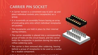
CARRIER PIN SOCKET
• A Carrier Socket is a convenient way to pick-up and place
individual sockets pins (receptacles) as a group.
• It is essentially an assembly fixture having an array of
protruding pins onto which individual receptacles are
pushed.
• The receptacles are held in place by their internal spring
contacts.
• The carrier assembly is placed into a corresponding group
of holes on the circuit board, and the carrier holds the
receptacles in position during the wave or reflow
soldering cycle.
• The carrier is then removed after soldering, leaving
behind a group of receptacles to be used as a socket for a
leaded component.
• Many formats of carrier are available to match the
footprint of the device being socketed: DIP, SIP, PGA,
custom etc.
CARRIER PIN
TYPES:
Carrier Pin
Mating Pin
Dia.
0.152 to
2.591 mm
Pin
Mounting
Flush to
Board
Above
Board
BENEFITS OF CARRIER
SOCKETS:
• Carriers Sockets are more convenient than placing individual sockets on a
circuit board by hand with a pair of tweezers.
• At the other extreme, they do not require the expense of building a fully
automatic assembly machine with a programmable X-Y table.
• Using a Carrier Socket eliminates the insulator of a traditional socket and
provides lower socket profile.
• For high-speed circuitry, this results in a shorter electrical path (lower
inductance) and reduced propagation delay (no socket dielectric).
• One carrier can place the two different sizes of receptacle required by the
power and control pins.
• Allow solder joint inspection and improved air flow.
TYPICAL APPLICATIONS:
• For hand held devices such as mobile phones and PDAs, where
space is at a premium
• Carrier sockets are required for components that cannot go through
reflow, i.e. speakers and microphones.
• For socketing DCDC converters.
• For wave soldering receptacles into plated through holes. The added
weight of the carrier "holds-down" the components as the circuit
board passes over the solder wave.
• For surface mount assembly, where carrier assembly is placed into
plated through holes on the circuit board, and solder paste adjacent
to the holes is then reflowed before the carrier is removed.
VIDEO :
The video on next slide will illustrate how carrier pin
socket works for mounting receptacles into PC boards .
• Author Nalin P. Sheth, MBA Harvard, is Managing Director of
Champion Electronics Pvt. Ltd., Pune.
• Champion Electronics is serving electronics industry all over the
world from 1975.
• Contact Details :
• Email : sales@champelec.com
• Ph: +91-8928502180.
• Website :www.champelec.com

Carrier Pin Socket

  • 2.
    CARRIER PIN SOCKET •A Carrier Socket is a convenient way to pick-up and place individual sockets pins (receptacles) as a group. • It is essentially an assembly fixture having an array of protruding pins onto which individual receptacles are pushed. • The receptacles are held in place by their internal spring contacts. • The carrier assembly is placed into a corresponding group of holes on the circuit board, and the carrier holds the receptacles in position during the wave or reflow soldering cycle. • The carrier is then removed after soldering, leaving behind a group of receptacles to be used as a socket for a leaded component. • Many formats of carrier are available to match the footprint of the device being socketed: DIP, SIP, PGA, custom etc.
  • 3.
    CARRIER PIN TYPES: Carrier Pin MatingPin Dia. 0.152 to 2.591 mm Pin Mounting Flush to Board Above Board
  • 4.
    BENEFITS OF CARRIER SOCKETS: •Carriers Sockets are more convenient than placing individual sockets on a circuit board by hand with a pair of tweezers. • At the other extreme, they do not require the expense of building a fully automatic assembly machine with a programmable X-Y table. • Using a Carrier Socket eliminates the insulator of a traditional socket and provides lower socket profile. • For high-speed circuitry, this results in a shorter electrical path (lower inductance) and reduced propagation delay (no socket dielectric). • One carrier can place the two different sizes of receptacle required by the power and control pins. • Allow solder joint inspection and improved air flow.
  • 5.
    TYPICAL APPLICATIONS: • Forhand held devices such as mobile phones and PDAs, where space is at a premium • Carrier sockets are required for components that cannot go through reflow, i.e. speakers and microphones. • For socketing DCDC converters. • For wave soldering receptacles into plated through holes. The added weight of the carrier "holds-down" the components as the circuit board passes over the solder wave. • For surface mount assembly, where carrier assembly is placed into plated through holes on the circuit board, and solder paste adjacent to the holes is then reflowed before the carrier is removed.
  • 6.
    VIDEO : The videoon next slide will illustrate how carrier pin socket works for mounting receptacles into PC boards .
  • 7.
    • Author NalinP. Sheth, MBA Harvard, is Managing Director of Champion Electronics Pvt. Ltd., Pune. • Champion Electronics is serving electronics industry all over the world from 1975. • Contact Details : • Email : sales@champelec.com • Ph: +91-8928502180. • Website :www.champelec.com