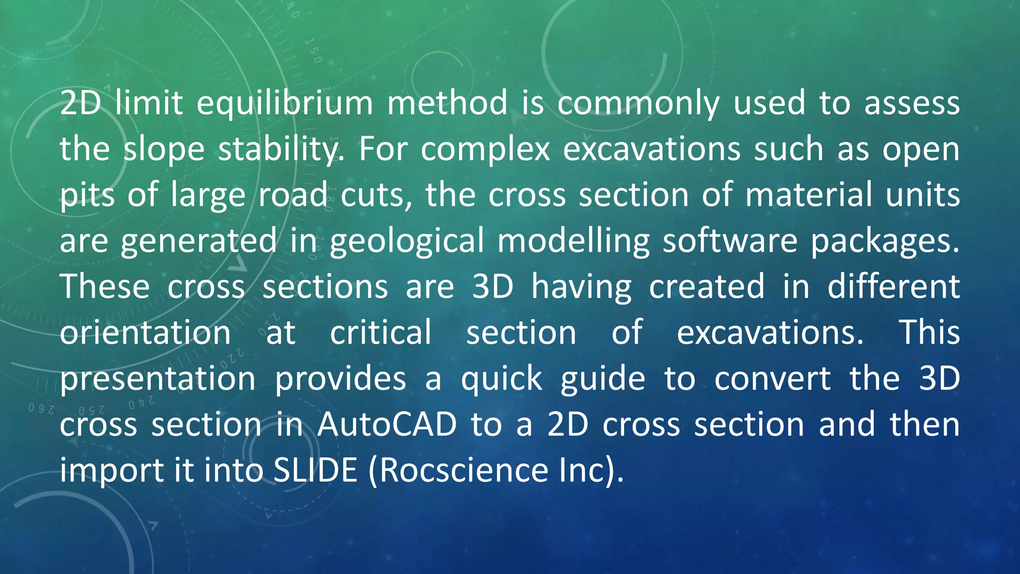
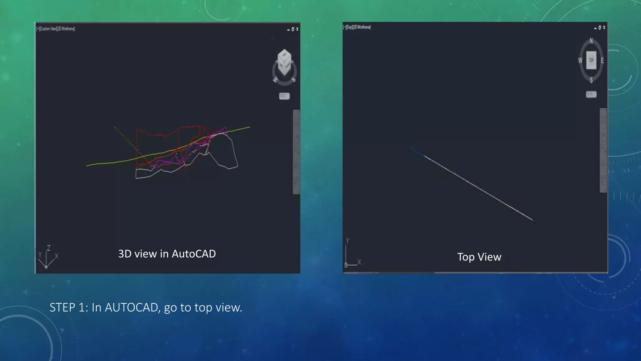
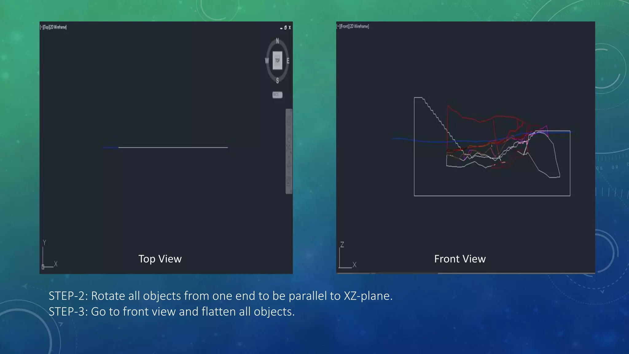
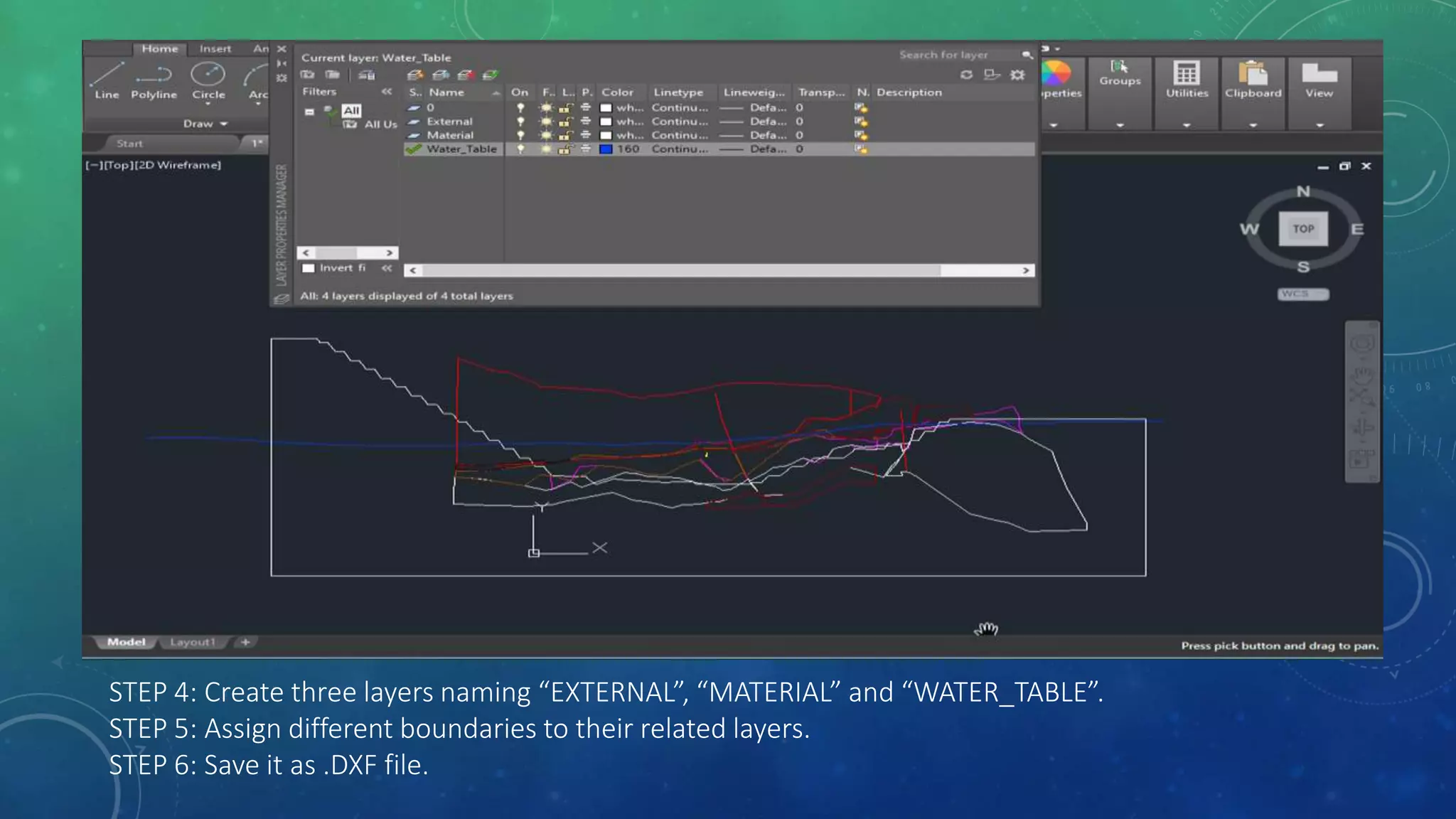
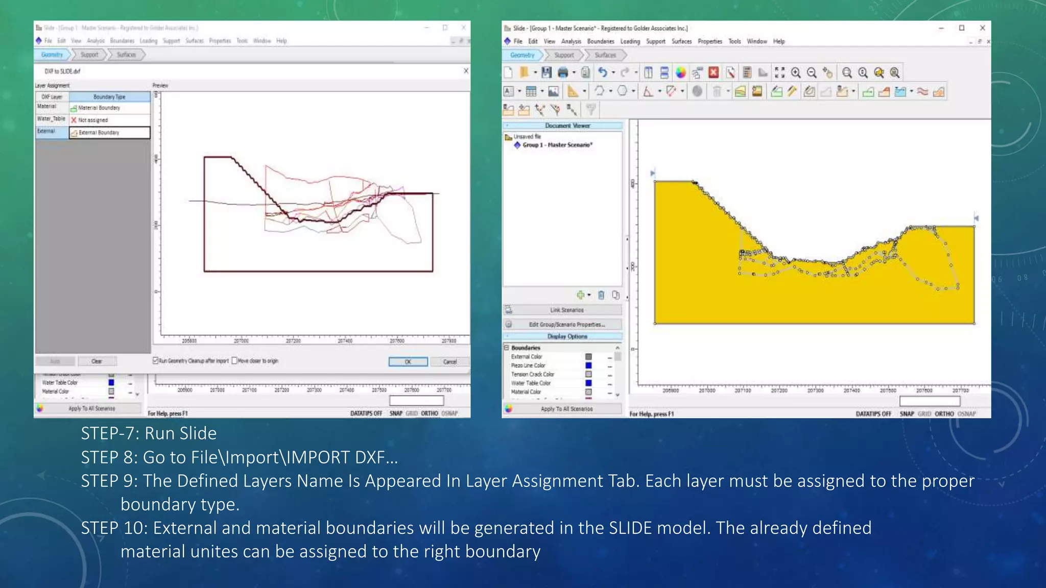
SLOPE STABILITY
BUILDING 2D SLIDE MODEL FROM
3D LITHOLOGY CROSS SECTION
2D limit equilibrium method is commonly used to assess
the slope stability. For complex excavations such as open
pits of large road cuts, the cross section of material units
are generated in geological modelling software packages.
These cross sections are 3D having created in different
orientation at critical section of excavations. This
presentation provides a quick guide to convert the 3D
cross section in AutoCAD to a 2D cross section and then
import it into SLIDE (Rocscience Inc).
STEP 1: In AUTOCAD, go to top view.
3D view in AutoCAD Top View
STEP-2: Rotate all objects from one end to be parallel to XZ-plane.
STEP-3: Go to front view and flatten all objects.
Top View Front View
STEP 4: Create three layers naming “EXTERNAL”, “MATERIAL” and “WATER_TABLE”.
STEP 5: Assign different boundaries to their related layers.
STEP 6: Save it as .DXF file.
STEP-7: Run Slide
STEP 8: Go to FileImportIMPORT DXF…
STEP 9: The Defined Layers Name Is Appeared In Layer Assignment Tab. Each layer must be assigned to the proper
boundary type.
STEP 10: External and material boundaries will be generated in the SLIDE model. The already defined
material unites can be assigned to the right boundary

Building 2D SLIDE model from 3D lithology cross section

  • 1.
    SLOPE STABILITY BUILDING 2DSLIDE MODEL FROM 3D LITHOLOGY CROSS SECTION
  • 2.
    2D limit equilibriummethod is commonly used to assess the slope stability. For complex excavations such as open pits of large road cuts, the cross section of material units are generated in geological modelling software packages. These cross sections are 3D having created in different orientation at critical section of excavations. This presentation provides a quick guide to convert the 3D cross section in AutoCAD to a 2D cross section and then import it into SLIDE (Rocscience Inc).
  • 3.
    STEP 1: InAUTOCAD, go to top view. 3D view in AutoCAD Top View
  • 4.
    STEP-2: Rotate allobjects from one end to be parallel to XZ-plane. STEP-3: Go to front view and flatten all objects. Top View Front View
  • 5.
    STEP 4: Createthree layers naming “EXTERNAL”, “MATERIAL” and “WATER_TABLE”. STEP 5: Assign different boundaries to their related layers. STEP 6: Save it as .DXF file.
  • 6.
    STEP-7: Run Slide STEP8: Go to FileImportIMPORT DXF… STEP 9: The Defined Layers Name Is Appeared In Layer Assignment Tab. Each layer must be assigned to the proper boundary type. STEP 10: External and material boundaries will be generated in the SLIDE model. The already defined material unites can be assigned to the right boundary