BOOLEAN ALGEBRA, ARITHMETICAND COMBINATIONAL LOGIC CIRCUITS:
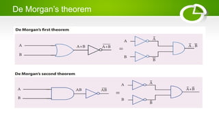
Basic laws of Boolean algebra - De Morgan’s theorem -
Verification of Boolean expression using Boolean laws - Half-
adder - Full adder - Half-Sub tractor- Full sub tractor (using basic
gates) – Encoder - Decimal to BCD encoder- Decoder -BCD to
decimal decoder.
3.
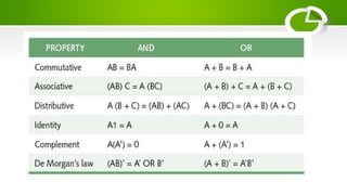
Basic laws ofBoolean algebra
• The basic laws of Boolean algebra are Commutative,
Associative, Distributive, Identity, Idempotent, Complement,
and De Morgan's laws. These laws are used to simplify Boolean
expressions, which are fundamental in digital electronics for
designing logic circuits.
Adder
• Addition isone of the most basic operations performed by different electronic
devices like computers, calculators, etc. The electronic circuit that performs the
addition of two or more numbers, more specifically binary numbers, is called as
adder. Since, the logic circuits use binary number system to perform the operations,
hence the adder is referred to as binary adder.
7.
What is aHalf-Adder?
• A combinational logic circuit which is designed to add two
binary digits is called as a half adder. The half adder provides
the output along with a carry value (if any). The half adder
circuit is designed by connecting an EX-OR gate and one AND
gate. It has two input terminals and two output terminals for
sum and carry.
9.
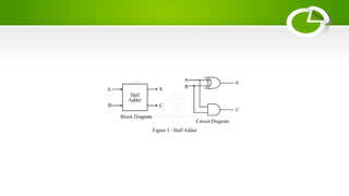
• From thelogic circuit diagram of half adder, it is clear that A
and B are the two input bits, S is the output sum, and C is the
output carry bit.
• In the case of a half adder, the output of the EX-OR gate is the
sum of two bits and the output of the AND gate is the carry.
Although, the carry obtained in one addition will not be
forwarded in the next addition because of this it is known as
half adder.
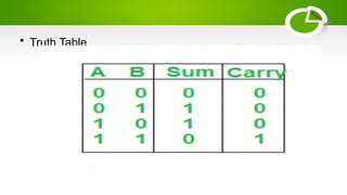
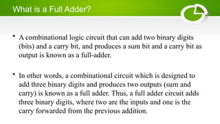
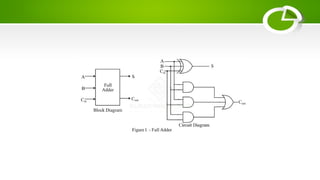
What is aFull Adder?
• A combinational logic circuit that can add two binary digits
(bits) and a carry bit, and produces a sum bit and a carry bit as
output is known as a full-adder.
• In other words, a combinational circuit which is designed to
add three binary digits and produces two outputs (sum and
carry) is known as a full adder. Thus, a full adder circuit adds
three binary digits, where two are the inputs and one is the
carry forwarded from the previous addition.
13.
Operation of FullAdder
• Full adder takes three inputs namely A, B, and Cin. Where, A
and B are the two binary digits, and Cin is the carry bit from
the previous stage of binary addition. The sum output of the full
adder is obtained by XORing the bits A, B, and Cin. While the
carry output bit (Cout) is obtained using AND and OR
operations.
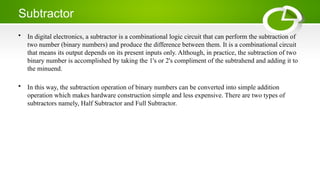
Subtractor
• In digitalelectronics, a subtractor is a combinational logic circuit that can perform the subtraction of
two number (binary numbers) and produce the difference between them. It is a combinational circuit
that means its output depends on its present inputs only. Although, in practice, the subtraction of two
binary number is accomplished by taking the 1's or 2's compliment of the subtrahend and adding it to
the minuend.
• In this way, the subtraction operation of binary numbers can be converted into simple addition
operation which makes hardware construction simple and less expensive. There are two types of
subtractors namely, Half Subtractor and Full Subtractor.
16.
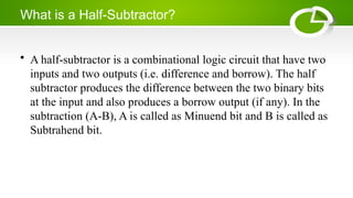
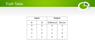
What is aHalf-Subtractor?
• A half-subtractor is a combinational logic circuit that have two
inputs and two outputs (i.e. difference and borrow). The half
subtractor produces the difference between the two binary bits
at the input and also produces a borrow output (if any). In the
subtraction (A-B), A is called as Minuend bit and B is called as
Subtrahend bit.
18.
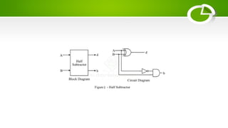
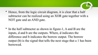
• Hence, fromthe logic circuit diagram, it is clear that a half
subtractor can be realized using an XOR gate together with a
NOT gate and an AND gate.
• In the half subtractor as shown in figure-1, A and B are the
inputs, d and b are the outputs. Where, d indicates the
difference and b indicates the borrow output. The borrow
output (b) is the signal that tells the next stage that a 1 has been
borrowed.
19.
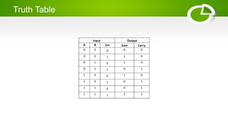
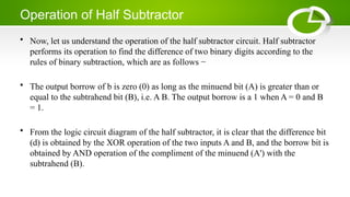
Operation of HalfSubtractor
• Now, let us understand the operation of the half subtractor circuit. Half subtractor
performs its operation to find the difference of two binary digits according to the
rules of binary subtraction, which are as follows −
• The output borrow of b is zero (0) as long as the minuend bit (A) is greater than or
equal to the subtrahend bit (B), i.e. A B. The output borrow is a 1 when A = 0 and B
= 1.
• From the logic circuit diagram of the half subtractor, it is clear that the difference bit
(d) is obtained by the XOR operation of the two inputs A and B, and the borrow bit is
obtained by AND operation of the compliment of the minuend (A') with the
subtrahend (B).
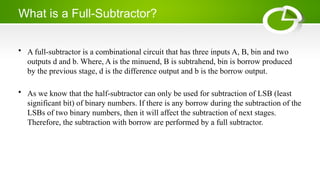
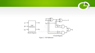
What is aFull-Subtractor?
• A full-subtractor is a combinational circuit that has three inputs A, B, bin and two
outputs d and b. Where, A is the minuend, B is subtrahend, bin is borrow produced
by the previous stage, d is the difference output and b is the borrow output.
• As we know that the half-subtractor can only be used for subtraction of LSB (least
significant bit) of binary numbers. If there is any borrow during the subtraction of the
LSBs of two binary numbers, then it will affect the subtraction of next stages.
Therefore, the subtraction with borrow are performed by a full subtractor.
23.
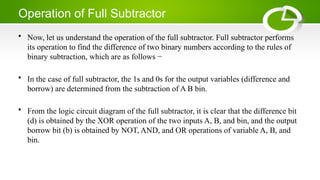
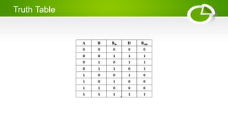
Operation of FullSubtractor
• Now, let us understand the operation of the full subtractor. Full subtractor performs
its operation to find the difference of two binary numbers according to the rules of
binary subtraction, which are as follows −
• In the case of full subtractor, the 1s and 0s for the output variables (difference and
borrow) are determined from the subtraction of A B bin.
• From the logic circuit diagram of the full subtractor, it is clear that the difference bit
(d) is obtained by the XOR operation of the two inputs A, B, and bin, and the output
borrow bit (b) is obtained by NOT, AND, and OR operations of variable A, B, and
bin.
What is anEncoder?
• An encoder is a digital combinational circuit that converts a human friendly
information into a coded format for processing using machines. In simple words, an
encoder converts a piece of information normal form to coded form. This process is
called encoding.
• Encoders are crucial components in various digital electronics applications such as
data transmission, controlling and automation, communication, signal processing,
etc.
• An encoder consists of a certain number of input and output lines. Where, an encoder
can have maximum of "2n" input lines whereas "n" output lines. Hence, an encoder
encodes information represented by "2n" input lines with "n" bits.
27.
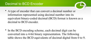
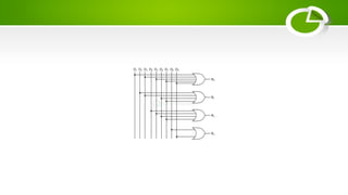
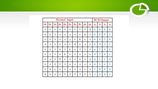
Decimal to BCDEncoder
• A type of encoder that can convert a decimal number or
information represented using decimal number into its
equivalent binary-coded decimal (BCD) format is known as a
decimal to BCD encoder.
• In the BCD encoding scheme, each decimal digit can be
converted into a 4-bit binary representation. The following
table shows the BCD equivalents of decimal digital from 0 to 9.
30.
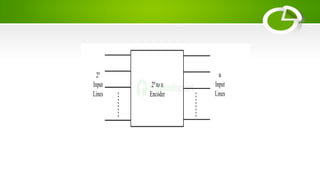
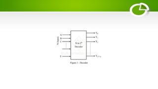
What is aDecoder?
• In digital electronics, a combinational logic circuit that converts an N-bit binary input code into M output
channels in such a way that only one output channel is activated for each one of the possible combinations of
inputs is known as a decoder.
• In other words, a combinational logic circuit which converts N input lines into a maximum of 2N output lines is
called a decoder.
• Therefore, a decoder is a combination logic circuit that is capable of identifying or detecting a particular code.
The operation that a decoder performs is referred to as decoding. A general block diagram of a decoder is shown
in Figure-1.
32.
Block Diagram ofa Decoder
• Here, the decoder has N input lines and M (2N) output lines. In
a decoder, each of the N input lines can be a 0 or a 1, hence the
number of possible input combinations or codes be equal to 2N.
For each of these input combinations, only one of the M output
lines will be active, and all other output lines will remain
inactive.