Beginners Guide to TikTok for Search - Rachel Pearson - We are Tilt __ Bright...
Blackmer LPG pumps & Compressors cb281.ppt
1. 1 07/98 CB-2xx
Hilites Only
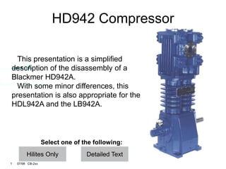
HD942 Compressor
This presentation is a simplified
description of the disassembly of a
Blackmer HD942A.
With some minor differences, this
presentation is also appropriate for the
HDL942A and the LB942A.
Select one of the following:
Detailed Text
3. 3 07/98 CB-2xx
Literature
Have the literature for
your machine at hand
• Parts lists
• Installation, Operation
and Maintenance
manual
Call your Blackmer
distributor for
literature or go to our
website:
www.blackmercompressor.com
4. 4 07/98 CB-2xx
Literature
Be sure that you have the
appropriate literature before
starting work on the
compressor. Locate the parts
list and Installation, Operation
and Maintenance instructions.
In addition, you may have
received additional instruction
sheets with your machine that
further describe such items as
valves and packing.
If you do not have all of the
necessary information, call
your Blackmer distributor.
Literature is also available on
our website:
www.blackmercompressor.com
5. 5 07/98 CB-2xx
Tools
• Use standard tools
for small machines
• Blackmer adjustable
spanner with 1/4”
pins (p/n 790316)
• Blackmer spanner
(p/n 790535) for
valve hold down
screws
• Packing installation
Cone (p/n 790540)
• Inside snap ring
pliers
6. 6 07/98 CB-2xx
Tools
Blackmer offers a complete tool kit
which has all of the hand tools
necessary to dismantle the machine.
The tools normally required for small
machine service will be adequate for
the work on an HD compressor. A
small strap wrench is useful and a
good spanner. The adjustable spanner
(p/n 790316) has 1/4” pins and is used
for piston removal. The Blackmer
spanner (p/n 790535) is used for valve
hold down screws. An Installation
Cone p/n 790540 should be used to
protect the packing during assembly.
A flat scraper and inside snap ring
pliers are also needed.
On the HD942 a small hoist will be
needed.
7. 7 07/98 CB-2xx
Nameplate • Model number
• Serial number
• I.D. number
Defines construction
• Oil capacity
• Rod inspection
access
8. 8 07/98 CB-2xx
Nameplate
On the side of every
Blackmer compressor is a
nameplate which doubles as
an access opening for
inspecting the piston rods.
The nameplate will show the
compressor’s model number,
serial number, ID number, and
oil capacity.
The compressor ID is a
coded number that describes
the compressor’s construction.
Make certain that you have
these identifying numbers
when you call your Blackmer
distributor for parts or service
assistance.
10. 10 07/98 CB-2xx
HD942
The HD942A is a single-stage,
non-lubricated, reciprocating,
double-acting compressor
designed to handle many different
gasses. It is rated for up to 50 bhp
(37kw) and operates generally
between 400-825 rpm.
The HD942A has an air-cooled
head and cylinder.
12. 12 07/98 CB-2xx
HDL942
Blackmer also offers the
water-cooled model HDL942A.
Note the water jacket covers on
each side of the cylinder and
on top of the cylinder heads.
Smaller models are available.
14. 14 07/98 CB-2xx
Cylinder Drain &
Distance Piece
Drain
The port on each side of
the cylinder may be used as
a cylinder drain. A pressure
port is provided at both the
suction and discharge
flanges.
Each side of the distance
piece has two openings. The
lower opening may be used
as a drain, while the upper
may be used as a vent or
purge connection.
Not shown: Beneath the
lower valve on each side of
the cylinder may be vent or
purge connections for the rod
seals.
15. 15 07/98 CB-2xx
Head with
Standard
Suction Valves
The HD942A is a 2 cylinder
double-acting compressor.
Each cylinder end is fitted
with both a suction valve and
a discharge valve for a total
of 4 each. All 4 suction
valves are on one side of the
compressor; the 4 discharge
valves are on the other side.
16. 16 07/98 CB-2xx
Removing
Standard
Valves Remove hold down
screw from valve cap
Reinstall cover plates
first, then the hold
down screws.
O-rings are not
normally reusable
17. 17 07/98 CB-2xx
Removing
Standard
Valves
(part 1)
Remove the valve caps to
access the valves. After the
valve caps have been
removed, the valve hold
down screws can be removed
with a spanner wrench
(Blackmer PN 790535). To
prevent possible damage to
the valves during reassembly,
the hold down screws must
be completely removed from
the valve cover plates.
18. 18 07/98 CB-2xx
Removing
Standard
Valves
(part 2)
Once the valve caps and
hold down screws have been
removed, the cover plates
may be removed. During
reassembly the valve cover
plates must be installed first,
then the hold down screws.
Note the O-ring under each
valve cap and cover plate.
The compressor I.D. number
on the nameplate contains a
code for the O-ring material
used. Typically, O-Rings are
not reusable and should be
replaced any time the cover
plates are removed.
19. 19 07/98 CB-2xx
Valves
Valve cages
Valves
Gaskets - usually
iron
Always replace
gaskets
Reinstall valves in
correct ports
20. 20 07/98 CB-2xx
Valves
With the cover plates
removed, the valve cage, valve
and gasket may be taken out.
Make sure the valve gaskets
are removed with each valve.
When they are left in the head,
they may be very difficult to
see. The valve gaskets are
normally iron although other
materials are occasionally
used. Valve gaskets should be
replaced anytime the valves
are removed.
Suction and discharge valves
must be reinstalled in the
correct ports.
21. 21 07/98 CB-2xx
Head with
Suction Valve
Unloaders
Loadless starting
Constant speed
operation
22. 22 07/98 CB-2xx
Head with
Suction Valve
Unloaders
Optional suction valve unloaders
allow the compressor to be
deactivated in service. That is, gas
that is drawn into the cylinder
during the suction stroke is expelled
through the suction valve on the
discharge stroke and does not pass
through the machine into the
discharge line. This is accomplished
by holding the compressor suction
valve plates open throughout the full
cycle. The unloader mechanism
does this mechanically and can be
powered by compressed gas from
the discharge storage or an
independent source, as required.
The suction valves can be
unloaded to produce no-load starts
or reduced capacity operation on
demand.
See bulletin CB-039 for more
information.
23. 23 07/98 CB-2xx
Removing
Suction Valves
with Unloaders • Unloader Assembly
• O-ring
• Unloader Plunger
• Remove hold down
screw from valve cap
24. 24 07/98 CB-2xx
Removing
Suction Valves
with Unloaders
Use a strap wrench to remove
the unloader assembly and its O-
ring. Alternately, a bar can be
levered against a pair of unloader
cap screws.
Once the unloader assembly is
removed, the unloader plunger
and valve hold down screw can
be removed.
When assembling, make sure
the cover plate is firmly secured
before reinstalling the hold down
screw.
26. 26 07/98 CB-2xx
Suction Valve
Removal
Once the hold down screw is
removed, the cover plate and its
O-ring can be removed. Under
the cover plate is the valve cage,
suction valve with unloader
actuator, and a valve gasket.
27. 27 07/98 CB-2xx
Suction Valve
Unloaders
• PTFE Unloader
piston seals
• All Stainless Steel
Parts
28. 28 07/98 CB-2xx
Suction Valve
Unloaders
The unloader assembly
consists of a cap, body with O-
ring, and a piston with two spring
loaded PTFE seals. The open
side of the seals should face
outward. The unloader actuator
and spring are held to the valve
with a snap ring.
The unloader cap, body piston,
actuator and spring are all
stainless steel.
30. 30 07/98 CB-2xx
Disassembled
Valves A disassembled suction
valve is shown above and a
discharge valve is below.
Each valve consists of a seat,
bumper, springs, plate,
threaded post, nut and
lockwashers.
32. 32 07/98 CB-2xx
Cylinder Head
Unbolt the four head bolts
from the top of each head and
lift the heads out. Note the O-
rings under each head.
33. 33 07/98 CB-2xx
Piston Removal
Remove piston cap
with 1/4” pin spanner
Upper shims are
under the piston cap
Lower shims are
under the piston
Shims adjust deck
height
4 rings & expanders
on each piston
34. 34 07/98 CB-2xx
Piston Removal
Bring the piston to top-dead-
center and remove the piston nut.
Remove the piston cap using the
two ¼” puller holes (the oil pump
cover bolts may be used). Note
the O-ring and a number of shims
under the piston cap. Lift out the
piston assembly. Under the piston
there are one or more shims. The
upper and lower shims are used
to adjust the height of the piston in
the cylinder. Keep the shim sets
together to simplify reassembly.
Bring the other piston to top-dead-
center for removal.
Each piston is fitted with four
piston rings. Each ring has a
stainless steel expander behind it.
36. 36 07/98 CB-2xx
Piston
Installation When installing the piston
rings and expanders make
sure that each piston ring is
installed with its gap 1800 from
the expander gap. Also, the
piston ring gaps should be
staggered around the piston.
38. 38 07/98 CB-2xx
Piston
Clearance Since the HD942 is a double-
acting compressor, both the
upper and lower piston
clearance must be set. This is
done via shims under the
piston and between the piston
body and piston head. The
piston clearance is measured
with the valves removed.
40. 40 07/98 CB-2xx
Cylinder
Removal With the pistons removed,
the cylinder can be unbolted
and lifted off with the use of a
hoist. Do not allow the upper
packing boxes to be lifted off
with the cylinder as the packing
will be damaged.
41. 41 07/98 CB-2xx
Upper Packing
Box Removal • Note packing box
orientation
• Use packing
installation cone
• Some boxes have
vent rings
42. 42 07/98 CB-2xx
Upper Packing
Box Removal
Note the orientation of the
upper packing boxes. Place
the packing installation cones
over the ends fo the piston
rods, then carefully lift the
upper packing boxes and O-
rings off the top of the piston
rods. Remove the oil deflector
rings from the rods.
This picture shows two
styles of packing boxes: one
with and one without vent
rings.
44. 44 07/98 CB-2xx
Upper Packing
Box Detail Some models will
have two vent rings
and two O-rings on
the each packing box.
Other models will
have only a single O-
ring and no vent rings.
45. 45 07/98 CB-2xx
Upper Packing
Box
Disassembly Packing gland
Packing cups with
seals
Packing cup gasket
46. 46 07/98 CB-2xx
Upper Packing
Box
Disassembly
Removal of the packing
gland from the bottom of the
packing box will allow the
individual packing cups to be
removed. Each packing cup
will have an O-ring and will
contain a packing seal. The
number of packing cups and
the types of seals they contain
may vary from the picture. A
gasket fits between the upper
packing cup and the top of the
packing box.
47. 47 07/98 CB-2xx
Seal Detail Seal ring pairs
Tangential-
Tangential
Radial-Tangential
Keep seals
together
Note match marks
TT
RT
48. 48 07/98 CB-2xx
Seal Detail Most seal rings come in
pairs and may be Tangential -
Tangential (shown on the left)
or Radial-Tangential (shown
on the right). They each
consist of 3 carbon pieces
with a spring around the
circumference.
Keep individual seal pairs
together. Pay attention to the
locating pins and match
marks.
TT
RT
49. 49 07/98 CB-2xx
Lower Packing
Box Removal
Remove hold down
screw with spanner
Hold down screw
has plastic insert
Packing box O-ring
50. 50 07/98 CB-2xx
Lower Packing
Box Removal The packing boxes are
secured by a hold down screw
which is removed with an
adjustable spanner. Notice that
the hold down screw also has a
plastic insert that keeps it in
place. Next, the packing boxes
themselves may be lifted off
the rod. O-Rings seal the
bottom of the packing boxes.
51. 51 07/98 CB-2xx
Lower Packing
Box
Disassembly
Use a screwdriver
handle to depress
the spring while
removing the
retainer ring
V-rings
Spring is next to
the male seal ring
52. 52 07/98 CB-2xx
Lower Packing
Box
Disassembly
Use a pair of inside snap ring
pliers to remove the top snap
ring. The handle of a
screwdriver can be used to
slightly depress the spring to
make this operation easier.
With the snap ring out, the top
washer, the spring, the middle
washer, the seal, the bottom
washer and retainer ring can all
be removed. The seal consists
of three types of rings. A male
ring, a series of V-rings, then a
female ring. The seal
orientation will depend on the
operating pressures; however,
the spring and washer always
press against the male ring.
53. 53 07/98 CB-2xx
Piston Rod
Inspection
Piston rods and tops
of the crossheads
are visible through
the nameplate
opening
54. 54 07/98 CB-2xx
Piston Rod
Inspection
The piston rods and the top
of the crossheads are visible
through the opening when the
nameplate is removed.
55. 55 07/98 CB-2xx
Crankcase and
Crossheads
Gasket fits between
crankcase & guide
Access cover &
gasket
Connecting rod
nuts are removed
to take out
crosshead &
connecting rod
Dipstick
56. 56 07/98 CB-2xx
Crankcase and
Crosshead
The crosshead guide may
now be removed, exposing
the crosshead/piston rod
assemblies. Removal of the
crankshaft access cover and
gasket allows access to the
connecting rods. After the
bottom cap of the connecting
rod has been removed, the
piston rod/crosshead and the
top half of the connecting rod
may be lifted off from above.
Keep each connecting rod
with its proper cap.
A scraper may be needed to
remove the flat gasket that fits
on top of the crankcase..
57. 57 07/98 CB-2xx
Never remove
piston rod from
crosshead
Ductile iron rod
Press out wrist pin
Plastic retainer
plugs
Crosshead
58. 58 07/98 CB-2xx
Remove the wrist pin with a
press to separate the
connecting rod from the
crosshead assembly. The
piston rod is permanently
secured to the crosshead at
the factory and no attempt
should be made to separate
them. Note the plastic
retainer plug on each end of
the wrist pin.
Crosshead
59. 59 07/98 CB-2xx
Connecting Rod
Ductile iron rod
Split bearing on the
crank end
Tabs on bearings
fit in slots in rod
and cap
Keep rod caps on
correct rod and
note match marks
60. 60 07/98 CB-2xx
Connecting Rod
The ductile iron connecting rod
is ported to route oil to the wrist
pin and the bronze bushing.
When the bronze bushing is
replaced, it must be honed to the
final dimensions after being
pressed into the connecting rod.
The hole in the bushing must also
align with the oil passage port.
An automotive type split bearing
is on the crankshaft end. Tabs on
the bearings fit into slots in the
rod and cap. This keeps the
bearing from spinning and lines
up the hole with the rifle drilled
port. Keep each connecting rod
cap with its matching rod. Match
marks are provided on the rod
and cap to ensure proper
orientation.
62. 62 07/98 CB-2xx
The oil pressure adjustment
screw and locknut fits into the
oil pump. Turning the screw
inward (clockwise) increases
the oil pressure setting.
The oil level dipstick, oil
pressure gauge, and external
oil filter are all shown in this
view.
Oil Pressure
Adjustment
64. 64 07/98 CB-2xx
Note the upper and lower oil
level marks which have been
hi-lighted in white in the
picture. The oil level must be
within these marks.
Dipstick
66. 66 07/98 CB-2xx
The oil pickup strainer
screen with washers and O-
ring fits in the crankcase
under the bearing carrier. If
any foreign material is noted
on the strainer, its source
should be quickly identified to
prevent reoccurrence of the
problem. The pipe plug next
to the oil pickup tube opening
is the crankcase oil drain.
Oil Inlet
Strainer
70. 70 07/98 CB-2xx
Oil Pump Detail A disassembled oil pump
with the oil pressure adjusting
screw and the external oil
filter.
Note that the oil pump parts
have match marks. Also note
the drive tab at the back of the
pump - this tab fits into a slot
in the end of the crankshaft.
71. 71 07/98 CB-2xx
Bearing carrier
gasket
Oil pump drive slot
and crankshaft
drive pin
Orient crankshaft
Do not scar
surfaces
Bearing Carrier
& Crankshaft
Removal
72. 72 07/98 CB-2xx
The entire bearing carrier /
oil pump assembly with gasket
may be removed as one.
Note the slot in the end of the
crankshaft. When the bearing
carrier is reinstalled, this slot
must align with the drive tab in
the oil pump.
The crankshaft is readily
removed once oriented
correctly. Be careful not to
scar the bearing or journal
surfaces when removing the
crankshaft.
Bearing Carrier
& Crankshaft
Removal
73. 73 07/98 CB-2xx
Pressure lubrication
holes at the journal
bearings
Oil spray nozzles on
the crankshaft for the
crossheads
Crankshaft
Detail
74. 74 07/98 CB-2xx
Note the lubrication holes on
the bearing journals and the
spray nozzles on the
crankshaft. These holes and
the passageways inside the
crankshaft must be clean.
Crankshaft
Detail
75. 75 07/98 CB-2xx
Located at flywheel
end
Shims adjust main
bearing preload
Shims are reusable
Adjusted for new
main bearing or new
crankshaft
Cover contains
crankshaft oil seal
Bearing Cover
Plate
76. 76 07/98 CB-2xx
The bearing cover plate is
on the flywheel side of the
crankcase. Behind this plate
are shims which adjust the
preload on the main bearings.
These shims are normally
reusable and the shim
thickness will not have to be
adjusted unless the crankshaft
and/or main bearings are
replaced. The bearing cover
plate also contains a
crankshaft oil seal.
Bearing Cover
Plate
77. End of Presentation
1809 Century Avenue
Grand Rapids, MI, USA 49503
Ph: 616-241-1611
Fax: 616-241-3752
www.blackmer.com