SlideShare a Scribd company logo
1 of 15
Download to read offline
US006186445B1
(12) United States Patent (10) Patent N0.: US 6,186,445 B1
Batcho (45) Date of Patent: Feb. 13, 2001
(54) METHOD AND APPARATUS FOR OTHER PUBLICATIONS
MITIGATING JUNCTION FLOWS Williams et al, “A Comprehensive Plan for Helicopter Drag
(76) Inventor: Paul E Batcho 12 Humbert SL Reduction”, The American Helicopter Society, May 1975*
Princeton, NJ (US) 08540 * Cited by examiner
(*) Notice: Under 35 U.S.C. 154(b), the term of this Primary Examiner—Ga1en L' Barefoot _
patent Shall be extended for 0 days_ (74) Attorney, Agent, or Firm—MatheWs, Collins,
Shepherd & Gould, PA.
(21) Appl. No.: 09/263,592 (57) ABSTRACT
(22) Filedi Mall 5, 1999 An apparatus and method for mitigating the formation of the
necklace vortex in junction ?oWs is disclosed. A lifting
structure for inducing a positive lift vector and having at
least one tip for inducing an outWard How is placed ahead of
Related US. Application Data
(60) Provisional application No. 60/077,103, ?led on Mar. 6,
1998' the WindWard side of an obstacle at Which a necklace vorteX
(51) Int. Cl.7 ..................................................... B64C 23/06 Would be formed. The structure has a bottom surface and is
(52) US. Cl. ............................................. 244/130; 244/199 placed above the boundary ?oor plane (eg, a plane from
(58) Field of Search ..................................... 244/199, 130; Which the Obstacle protrudes), by a Su?icient distance to
138/37_38; 52/84 alloW a ?oW?eld to travel betWeen the bottom surface of the
structure and the ?oor plane. Exemplary applications for the
(56) References Cited invention include reducing scouring at bridges and bridge
like piers or supports, reducing acoustic signature of sub
U-S~ PATENT DOCUMENTS marine operations, protecting architectural structures and
2 650 752 * 9/1953 Hoadley ............................... 244/130 reducing Wind gusts> mitigating Wind haZardS for geological
371017920 * 8/1963 Fradenburgh _ 244/130 structures, and enhancing performance of aircraft.
4,569,494 * 2/1986 Sakata ......... .. 244/199
5,772,155 * 6/1998 Nowak ............................... .. 244/199 21 Claims, 6 Drawing Sheets
U.S. Patent Feb. 13, 2001 Sheet 1 6f 6 US 6,186,445 B1
FIG. 1A
FIG. 1C
U.S. Patent Feb. 13, 2001 Sheet2 0f6
FIG. 2
B
‘W .ullm
i] ‘tr ‘ k‘lv iJ * '
20 14a
10
FIG. 3
US 6,186,445 B1
U.S. Patent Feb. 13, 2001 Sheet 3 6f 6 US 6,186,445 B1
FIG. 4A FIG- 4B
8
is H‘ is? W i» 10IS"
FIG. 40 FIB- 4D
§
1 i
21 /40
U.S. Patent Feb. 13, 2001 Sheet 4 6f 6 US 6,186,445 B1
FIG. 58FIG. 5A
FIG. 50FIG. 5C
FIG. 5FFIG. 5E
U.S. Patent Feb. 13, 2001 Sheet 5 6f 6 US 6,186,445 B1
FIG. 6A FIG. 5B
U.S. Patent Feb. 13, 2001 Sheet 6 6f 6 US 6,186,445 B1
FIG. 10
US 6,186,445 B1
1
METHOD AND APPARATUS FOR
MITIGATING JUNCTION FLOWS
RELATED APPLICATIONS
Applicant claims priority based upon US. Pat. application
Ser. No. 60/077,103 ?led Mar. 6, 1998.
FIELD OF THE INVENTION
The invention relates to a method and apparatus for
mitigating junction ?oWs, and in particular, to a method and
apparatus for reducing the effects of the necklace vortex on
objects comprising bridges, piers, buildings, aircraft,
submarines, and other architectural and geological struc
tures.
BACKGROUND OF THE INVENTION
The hydrodynamics associated With the ?oW of air, Water,
or any ?uid at the junction of tWo surfaces is common to
many engineering and natural structures. At the junction of
tWo solid surfaces, a highly unsteady and turbulent ?oW?eld
is established When a ?uid ?oWing over a surface encounters
an obstacle. See R. L. Panton, Incompressible Flow, (John
Wiley & Sons 1984), Which is hereby incorporated by
reference. This ?uid dynamic phenomenon (e.g., the
unsteady and turbulent ?oW?eld), has been referred to in the
?eld as the horseshoe vortex or the necklace vortex, and for
consistency of reference, the term “necklace vortex” Will be
used herein Which is intended to broadly encompass the
phenomenon.
Occurrences of the necklace vortex are found in many
manmade and naturally occurring circumstances and can
have adverse and hazardous effects from its presence. For
example, the necklace vortex can be found at the river ?oor
junction With a bridge pier, the junction of a submarine hull
and its sailplanes, the WindWard side of an architectural
structure such as a building, the junction of inlet struts in
hydrodynamic inlets such as in airbreathing engines and
intake systems of industrial poWer plants, the junction of
rotor and stator blades in turbines and compressors, the
junctions of an aircraft fuselage body and Wing, and in large
scale geological ?oWs at the foot of hills, mountains, and
volcanoes. In each case the necklace vortex may cause
adverse effects, some of Which are discussed beloW. See also
Bushnell, AERONAUTICAL JOURNAL, “Longitudinal
Vortex Control—Techniques and Applications” (October
1992), at pp. 293—312.
Bridge Pier Erosion
The ?oor of rivers are typically composed of soil that can
be transported by various shearing and mixing forces asso
ciated With the local ?oW of the river. The necklace vortex
that forms at bridge supports and piers causes highly
unsteady ?uid mixing at the WindWard side and adjacent side
regions of these obstacles. This unsteady ?oW causes erosion
not only of the piers and supports but also of the adjacent
riverbed, and sediment from the soil is forced into the river
?oW near the ?oor and then carried doWnstream. This event
is knoWn as scouring and can cause severe degradation of
bridge foundations, ultimately leading to bridge failure and
collapse. This degradation of bridge structural support has
long been recogniZed as a leading issue in public safety, and
it is estimated that damages from scouring are responsible
for up to 100 million dollars in the United States each year.
Thousands of bridges in the United States and abroad are
knoWn to be “scour critical.” See Rhodes and Trent, “Eco
nomics ofFloods, Scout; and Bridge Failures,” Proceedings
of the ASCE 1993 National Conference on Hydraulics
10
15
20
25
30
35
40
45
50
55
60
65
2
Engineering, Vol. I, San Francisco, Calif. (Jul. 25—30 1993),
at pp. 928—933; Young, “Risk Cost for Scour at Unknown
Foundations,” Proceedings of the ASCE Water Forum ‘92,
Baltimore, Md. (August 1992), and “National Bridges
Inventory Data,” US. Dept. of Transportation, Federal
HighWay Admin., Office of Engineering, Bridge Division
(1992), all of Which are incorporated herein by reference.
Submarine FloW?elds
The hull of a typical attack submarine is on the order of
several hundred feet or more, and boundary layers of siZable
extent develop along the surface of the hull. The various
control surfaces that intersect the hull (e.g., submarine sail),
cause a necklace vortex ?oW to form, and this localiZed
vortical ?oW can be ingested into the propeller, particularly
for the rearWard control surfaces. This ingestion of the
necklace vortex ?oW may produce acoustic noise and
degrade stealth characteristics of submarine operations.
Architectural Aerodynamics
Pressure systems and localiZed Wind gusts have long been
a problem for architectural designs for outdoor cafes and
meeting areas. When structures are subjected to oncoming
air ?oWs, unanticipated localiZed Wind gusts may occur
Which are a problem for local pedestrian traffic and exterior
design features.
When unobstructed Wind travels over the ground, the
speed of the Wind is much loWer at ground; in fact, the
theoretical boundary conditions or no-slip condition states
the speed is Zero at the ground. The speed increases from the
ground surface to above the ground, e.g., from Zero at the
ground to the freestream value of the Wind far above the
ground. This ?uid mechanic event is knoWn as the boundary
layer Which can be several tens or hundreds of feet high
(e.g., the height of the layer from the ground to the point
Where the Wind travels at the freestream value can be tens or
hundreds of feet). When Wind impacts the side of a building,
a necklace vortex is formed, and the high energy ?oW in the
upper part of the boundary layer is forced toWard the ground.
The necklace vortex can cause unsteady gusts of air near the
ground Which, among other things, are a problem for pedes
trian comfort and functionality of exterior designs.
Large Scale Geological FloWs
The occurrence of a necklace vortex system can be found
at the foot of the WindWard side of mountains, hills, volca
noes or other geological or naturally-occurring obstacles. As
discussed above, the necklace vortex is responsible for
dragging high energy air ?oWs from the upper part of the
boundary layer to the ground level. In geological ?oWs,
these boundary layers can be several hundred feet high, and
the necklace vortex can force atmospheric pollutants to the
ground and create adverse health haZards for the public and
Wildlife, in addition to causing adverse Wind conditions.
Aircraft Wing/Body Junctions, Inlet Struts, Rotor and Stator
Blade Junctions
Aerodynamic shaped surfaces may be in contact With a
surface having an engineering function. A necklace vortex
system may be formed at Wing/body junctions, engine inlets,
and internal engine components Which can be ingested into
engines, thus degrading engine performance or, in some
severe conditions, causing engine stall. The formation of
necklace vortex systems are also responsible for drag pen
alties on aircraft as Well as submarines.
Previous attempts at mitigating the effects of the necklace
vortex have applied the intuitive approach of adding positive
and negative vorticities to obtain Zero. Structures such as
strakes, ?llets, dillets, and triangular-shaped ramp plates
have been used to mitigate the necklace vortex Other efforts
have included using staked Washers, or large rocks placed
US 6,186,445 B1
3
around the pier (riprap), or vertical guide vanes protruding
from the riverbed. See Richardson, Harrison, and Davis,
“Evaluating Scour at Bridges,” FHWA-IP-90-017, Hydrau
lic Engineering Circular No. 18, (February 1991)
(incorporated by reference). None of these approaches have
proven to be of signi?cant long-term help in mitigating the
scouring problem and adverse affects of the necklace vortex.
Structural retro?ts have been suggested for other reasons.
For example, US. Pat. No. 5,478,167 to Oppenheimer et al.,
“Buoyant Matter Diverting System,” discloses a device
placed in front of a structure to protect the structure by
de?ecting ?oating debris aWay from it. The device of
Oppenheimer has a surface that is inclined to produce a
negative lift and a Wake doWnstream of the device and in
front of the obstacle, With the doWnstream Wake causing
?oating debris (e.g., ice, logs, trees, etc.), to de?ect aWay
from the structure (col. 3, 1. 40—50). The Oppenheimer
patent does not address the necklace vorteX or provide
insight into ?oor physics or scour.
Thus, there is a need to reduce the effect of the necklace
vorteX on objects such as bridges, bridge-like piers and
supports, submarines, architectural structures, aircraft, geo
logical features, and other obstacles affected by the vorteX.
SUMMARY OF THE INVENTION
Applicant has discovered that adverse effects of the
necklace vorteX can be mitigated by introducing a surface
inducing an upWard lift vector in front of an obstacle being
protected and above the ?oor or reference plane. This
invention applies counter-intuitive approaches, in that a tip
vorteX is introduced of the same rotational sense as the
necklace vorteX and the vorteX is addressed in an upper
?oW?eld. Summarily described, the invention embraces a
method of reducing the effect of a necklace vorteX generated
When a ?oW?eld contacts the side of an obstacle. The
obstacle Will have a certain thickness de?ning at least one
free space region and Will protrude above a reference plane.
The method comprises placing a Winged device in front of
the obstacle and above the reference plane (e.g., in an upper
?oW?eld), for directing the ?oW?eld aWay from the thick
ness of the obstacle toWard the at least one free space region
and for inducing velocity in the ?oW?eld adjacent the free
space region. Applicant has discovered that the necklace
vorteX can be reduced by relieving the spanWise gradients of
the ?oW?eld at the WindWard nose region of the obstacle,
thereby reducing the amount of vorteX stretching.
The invention also comprises an apparatus for reducing
the necklace vorteX comprising a Winged device for place
ment in front of the WindWard side of the obstacle and above
the reference plane on Which the obstacle may reside or be
suspended. The Winged device has a surface for inducing an
upWard lift vector and a ?oW?eld modi?cation for directing
the ?oW?eld in an outWardly direction (e.g., aWay from the
center of the obstacle). The inventive method and apparatus
mitigate the necklace vorteX and alloW ?uid to ?oW around
the obstacle in a less disrupted Way.
BRIEF DESCRIPTION OF THE DRAWINGS
For a better understanding of the invention, an exemplary
embodiment is described beloW, considered together With
the accompanying draWings, in Which:
FIG. 1A schematically illustrates a perspective vieW of
the necklace vorteX formed When a ?oW?eld encounters an
obstacle;
FIG. 1B schematically illustrates a perspective vieW of
the mitigating effects of the invention onn the necklace
vorteX (e.g., as compared With FIG. 1A);
10
15
25
35
45
55
65
4
FIG. 1C schematically illustrates a perspective vieW of
one embodiment of the inventive method and apparatus;
FIG. 2 schematically illustrates an alternative embodi
ment of the inventive method and apparatus as applied to an
abutment obstacle;
FIG. 3 schematically illustrates the effect of inventive
method and apparatus on the ?oW?eld;
FIGS. 4A—4D schematically illustrate top, front, and side
vieWs of the inventive apparatus of FIGS. 1 and 2, Wherein;
FIG. 4A re?ects a top vieW of the embodiment of FIGS.
FIG. 4B re?ects a top vieW of the embodiment of FIG. 2;
FIG. 4C re?ects a front vieW of the embodiment of FIGS.
FIG. 4D re?ects a side vieW of the embodiment of FIGS.
FIG. 4E re?ects a side vieW shoWing an alternative
placement of the inventive apparatus; and
FIG. 4E re?ects a perpective vieW shoWing an alternative
placement of the inventive apparatus;
FIGS. 5A—5F re?ect alternative embodiments of the
inventive apparatus as applied to a bridge support, illustrat
ing various alternative mounting devices;
FIGS. 6A—6D shoW effects of the invention, Wherein 6B
illustrates the three-dimensional relieving effect of the
invention (FIG. 6B), as compared With an unmitigated ?oW
(FIG. 6A), With streamlines sketched in a plane parallel With
the ?oor, and FIGS. 6C—6D are side and front vieWs,
respectively, illustrating the tip vorteX generated With the
invention;
FIG. 7 illustrates stretching and tilting of the incoming
two-dimensional boundary layer vorticity;
FIG. 8 illustrates an application of the invention to
mitigate submarine vorteX ?oWs;
FIG. 9 illustrates one embodiment of the inventive
method and apparatus to a geological structure comprising a
mountain; and
FIG. 10 illustrates one embodiment of the inventive
method and apparatus as applied to an aircraft; and
It is to be understood that these draWings are for the
purposes of illustrating the concepts of the invention, are not
limiting in nature, and are not to scale. The same character
references are used to denote corresponding features
throughout the ?gures.
DETAILED DESCRIPTION OF THE
INVENTION
The inventive method and apparatus mitigates the forma
tion of the necklace vorteX injunction ?oWs. The inventive
apparatus may be embodied in a Winged device comprising
at least one tip (usually tWo tips) and a lifting structure
having a bottom surface, Wherein the structure induces an
upWard positive lift (lift vector points aWay from the “?oor
plane” or “reference plane”). The upWard positive lift
induced by the lifting structure is associated With the net
effect of the surface of the structure, e.g., its upper and
bottom surfaces. The Winged device is placed ahead of the
side of an obstacle at Which a necklace vorteX is formed. The
device is positioned near to and above the ?oor plane by a
suf?cient distance to alloW a ?oW?eld to travel betWeen the
bottom surface and the ?oor plane. The at least one tip
directs the ?oW?eld in an outWardly direction aWay from the
obstacle. The inventive Winged device has been named the
“BAT WING,TM” and it Will be so referenced herein.
With reference to the ?gures, FIG. 1A schematically
illustrates a perspective vieW of the necklace vorteX 5 that is
US 6,186,445 B1
5
formed When a ?oW?eld “Fl” contacts a side of an obstacle
10, and FIG. 1B schematically illustrates the mitigating
effects of the inventive BAT WINGTM on the necklace
vortex. As can be seen in FIG. 1B, With the BAT WINGTM
20, the incoming ?oW?eld “F1” upon encountering the Wing
20 is directed aWay from the obstacle 10, producing a
modi?ed ?oW?eld “MF.” In FIG. 1C, there is shoWn a
perspective vieW of the invention, Without the necklace
vortex, to illustrate further details of the BAT WINGTM and
its operation.
Referring to FIG. 1C, the invention Will mitigate the effect
of the necklace vortex generated When a ?oW?eld “F1”
contacts the WindWard side 10a of an obstacle 10. The
obstacle 10 has a certain thickness “T” de?ning at least one
free space region 14a beyond the thickness. The obstacle 10
is shoWn schematically in FIGS. 1A—1C as a cylinder,
although it is contemplated that it may comprise any
obstacle obstructing a ?oW?eld at Which a necklace vortex
may be formed, including a building, bridge or pier support,
airplane Wing, submarine sail, geological feature, and so
forth. The obstacle Will in any case protrude above a bottom
reference plane or ?oor plane 40. Although the term “?oor
plane” is used to described this reference point, it of course
should be understood that the term “?oor” is not necessarily
being used in its conventional sense, as this reference plane
may comprise, among other things, the side of an airplane
from Which a Wing projects or the hull of a submarine, and
in the case of bridge piers, a local scour hole may exist
around the pier. Thus, “?oor plane” or “?oor” as used herein
does not imply a ?at surface. In a theoretical sense, the
reference plane, ?oor, or ?oor plane can be vieWed as the
plane at Which a physical boundary is introduced onto the
?oW. This boundary may be in relative motion itself, such as
is the case With riverbeds Where sandbars are formed from
the hydrodynamic forces on the sand that is dragged along
in the direction of the motion of the ?oW.
Referring still to FIG. 1C, the obstacle 10 projects from
the ?oor plane 40 and has a certain thickness “T” Which
de?nes at least one free space region 14a toWard Which the
?oW?eld “F1” Will travel upon hitting the obstacle. Typically
as shoWn in FIG. 1C, there Will be tWo free space regions
14a, 14b, on either side of the obstacle. HoWever, in some
cases there Will be only one free space region (as, for
example, When the obstacle comprises an abutment protrud
ing from the side of a structure or building or that associated
With a bridge). As an illustration, in FIG. 2 an abutment
obstacle 10 is shoWn protruding from the side of a structure
8, such that one free space region 14a is de?ned, and thus,
the BAT WINGTM is truncated as compared With the
embodiment of FIG. 1C.
The thickness T of the obstacle may impact upon the
preferred placement of the BAT WINGTM relative to the
obstacle, With its de?nition-depending on the application.
For example, in the case of a cylindrical obstacle as sche
matically shoWn in FIG. 1C, the thickness unit T is de?ned
as the diameter of the cylindrical cross-section of the
obstacle. In the case of an aerodynamically-shaped airfoil
structure, such as a sail on a submarine, the thickness unit
measure Would be taken as a dimensional length ranging
from betWeen the sail nose radius and the maximum thick
ness dimension of the structure (e.g., the sail). In the case of
a ?at-nosed or sharp-nosed bridge pier, an upper boundary
for the thickness unit Would be about the Width associated
With the cross-section frontal vieW of the pier (e.g., taken
along the WindWard face of the pier).
Referring still to FIG. 1C, in practicing the invention, the
Winged device, that is, the BATWING,TM is provided, which
10
15
25
35
45
55
65
6
comprises a lifting structure, as previously de?ned, and at
least one end, preferably tWo ends or tips 22a, 22b. The BAT
WINGTM also has a bottom surface 21 (e.g., FIG. 4C), Which
should be placed a certain height “H” above the ?oor plane
Which may be small but should be suf?cient to alloW a
?oW?eld to travel betWeen the bottom surface of the BAT
WINGTM and the ?oor plane. The total effect of the lifting
structure 20, by reason of its top and bottom surfaces, on the
?oW?eld is to create a positive lift vector (e.g., FIG. 3, arroW
“L”), Which implies an outWard ?oW, underneath the Wing,
developed toWard the Wing tips and near the ?oor plane. The
bottom surface 21 is adapted to direct the incoming ?oW?eld
“Fl” toWard the ?oor plane, and the lifting structure is
con?gured to induce velocity in the ?oW?eld, as illustrated
in FIG. 3. Advantageously, the lifting structure is con?gured
in the shape of an airfoil but other shapes may be used as
Well, such as rectangular, square, plate-like or block shapes,
and so forth, the important consideration being that the
con?guration of the structure induces a positive lift vector.
The BAT WINGTM is placed adjacent the side of the obstacle
so that When the ?oW?eld ?oWs toWards the obstacle, as
shoWn in FIGS. 1—3, the incoming ?oW?eld contacts the
lifting structure 20, the lifting structure directs the ?oW?eld
toWard the tips (22a, 22b) and free space regions (14a, 14b),
and the tips (or tip) induce velocity in the ?oW?eld. This
impact is also illustrated in FIGS. 6C—6D, shoWing a side
and front vieW, respectively, of the incoming ?oW?eld Fi
contacting the side of the lifting structure and being directed
outWard. The resulting ?oW?eld doWnstream of the BAT
WINGTM (e.g., the outgoing ?oW?eld “FO”) includes an
additional tip vortex 32 generated at the ends 22a, 22b, in the
free space regions 14a, 14b (e.g., FIGS. 6C—6D).
FloW?eld as used herein means the How of air, Water, or
any ?uid that may contact an obstacle and generate a
necklace vortex. The impact of the BAT WINGTM on the
?oW?eld is illustrated in FIG. 3 (Which for ease of reference
omits the obstacle). As can be seen, the positive lift vector
implies a doWnWash or doWnWardly-directed ?oW toWards
the ?oor plane, illustrated at arroW “D.” The doWnWash
occurs in the region directly behind the BAT WINGTM
although as can be seen, an upWard ?oW (illustrated at
arroWs “U”), occurs in the region beyond tips 22a, 22b. As
the BAT WINGTM is placed closer to the ?oor plane (e.g., as
“H” of FIG. 1C or FIG. 4C decreases), the outWard How is
enhanced, as the doWnWash “D” at the trailing edge or tip
(22a, 22b) of the BAT WINGTM is diverted outWard.
Referring noW to FIGS. 1C and 4A—4D, advantageously
the BAT WINGTM is placed a certain height “H” above the
reference plane or ?oor plane, and a certain distance “D”
(FIG. 4A), from the obstacle. The preferred placement of the
BAT WINGTM is de?ned by the distance “D” or trailing
location relative to the WindWard nose of the obstacle 10a
(FIGS. 4A, 4D), the spanWise length “S” of the BAT
WINGTM (FIGS. 4A—4B), the height of the bottom surface
21 of the BAT WINGTM above the ?oor plane 40 (FIG. 4C),
and the relative angle of attack 4) (FIG. 4D) of the BAT
WINGTM to the incoming ?oW?eld Fi. There is a propor
tional relation betWeen the height of the lifting structure
above the ?oor (H), and the magnitude of its lifting Wake’s
in?uence.
The measures H, D, and S may be related to the thickness
T, although their optimal values Will be application depen
dent. Generally, hoWever, the distance D for placing the
device in front of the obstacle 10 preferably is approxi
mately one to tWo thickness units The spanWise length
S of the BAT WINGTM lifting structure preferably is less
than or equal to one thickness unit. One-half a thickness unit
US 6,186,445 B1
7
(T) is likely to be a satisfactory value. An optimal height H
ranges from a minimal value (suf?cient for allowing the
?oW?eld to pass betWeen the bottom surface 21 of the BAT
WINGTM and the ?oor plane 40), to a maximum value Which
is on the order of about tWo span units (S) or one thickness
unit The preferred height H is affected by the ground
effect in?uence Which enhances the three dimensional
relieving effect of the BAT WINGTM. As the device is moved
aWay from the ?oor plane, the effect lessons; the direct
in?uence of the lifting structure’s Wake vorticity on the ?oor
vorticity may decrease linearly With increasing height H. As
shoWn in FIGS. 4E—4F, the structure Will have a trailing
edge 23 (e.g., the edge adjacent or facing the obstacle) Which
may touch the ?oor plane. All of the edge 23 may touch the
?oor plane 40, as in FIG. 4E, or only part of the edge, such
as that part de?ning the tips 22a, 22b, as in FIG. 4F. In these
cases, the tip vortex and outWard ?oW (three-dimensional
relieving effect), is still maintained. HoWever, preferably the
trailing edge is disposed above the ?oor plane so that at least
a minimal ?oW may pass betWeen the edge and the bottom
surface (e.g., FIG. 4D).
The angle of attack 4) is likely to be application dependent
and Will impact upon the magnitude of the Wake vorticity or
of the lift of the lifting structure; thus, it is related to the
amount of the three-dimensional relieving effect at the
WindWard (10a) side of the obstacle. For aircraft Wing/body
junctions and submarine sail/hull junctions, the BAT
WINGTM surface preferably is designed for an optimal lift to
drag ratio, and thus, an angle 4) (measured from a plane X
substantially parallel to the ?oor plane) (see, e.g., FIG. 4D),
of about less than 10 degrees Would be desirable. HoWever,
for a bridge pier application, Where drag is less of a concern,
the preferred angle of attack 4) Would be higher, e.g., about
tWenty to thirty degrees, so as to increase the doWnWash
underneath the BAT WINGTM While retaining reasonable
lifting properties and thus, more effectively utiliZing the
doWnWash’s conversion to spanWise ?oW at the ?oor.
There are various approaches by Which the lifting struc
ture may be suspended above the ?oor plane. For example,
FIGS. 5A—5F illustrate alternative embodiments of the
inventive apparatus as applied to a bridge support or pier
structure. FIG. 5A shoWs use of a strut mechanism 42 for
suspending the lifting structure 20 above the reference plane,
and FIG. 5B shoWs a base mounted system With use of a
pedestal structure 44. FIGS. 5C—5F shoW variations of
base-mounted and/or strut-mounted systems. FIG. 5C illus
trates a tidal ?oW application Where a BAT WINGTM is
mounted on both sides of the pier. Tidal ?oW changes
direction periodically, back and forth at about a 180 degree
change in direction, and thus, the WindWard side of the pier
changes as Well. Many tidal ?oWs are Well de?ned in
direction and thus, basically tWo dominant ?oW directions
are present. As shoWn in FIGS. 5D—5E, a base mount 44 may
be placed next to the obstacle and then a strut mechanism 42
attached to the base mount 44, re?ecting a combination of
base-mounted and strut-mounted systems. When a base is
placed next to the obstacle, as in FIGS. 5D—5E, it can be
clamped onto the obstacle at its WindWard side (10a—FIG.
4A, 4D), using a claW-type design or spring-loaded clamp
ing mechanism. AWind vane also could be incorporated into
the mounting system so that the BAT WINGTM could be
turned into the ?oW direction. FIG. 5F illustrates a triangular
mounting system Which could be useful in distributing
structural load forces ef?ciently.
The lifting structure mitigates the formation of the neck
lace vortex in at least tWo Ways. A transverse ?oW is
established at the bottom of the lifting structure and in the
10
15
25
35
45
55
65
8
near Wake; the outWard ?oW to the tip region causes the
streamlines in the ?oor region to have a more gradual
spanWise approach at the WindWard side of the obstacle
versus the unmitigated ?oW. FIGS. 6A and 6B illustrate the
three-dimensional relieving effect of the invention (FIG.
6B), as compared With an unmitigated ?oW (FIG. 6A), With
streamlines sketched in a plane parallel With the ?oor. This
more gradual outWard ?oW, or three-dimensional relieving
effect, tends to minimiZe spanWise gradients, (9/62, and thus
reduces the magnitude of the stretching (intensi?cation) of
the vorticity near the obstacle’s WindWard nose. The second
bene?cial effect is the induced velocity formed from the tip
vortex Which is found above the ?oor and to the side of the
obstacle (see, eg FIG. 1B).
Thus, With the invention, induced velocity opposes the
natural tendency of the necklace vortex to roll-up and thus
forces the streamlines to ?oW around the obstacle. The use
of an upWard lifting structure placed ahead of the obstacle is
a counter-intuitive approach as compared to traditional
insight into this phenomenon, since here, a tip vortex is
introduced of the same rotational sense as that of the
necklace vortex. Applicant has discovered that the intuitive
notation of adding positive and negative vorticity to get Zero
is in some regards incorrect. With this invention, the prob
lem has been moved aWay from the ?oor and into an upper
?oW?eld Where the tip vortex resides. This, hoWever, is a
useful result When ?oor erosion is a problem or the necklace
vortex is desired to be moved out of the path of a propeller
system.
The inventive method for junction ?oW mitigation of the
necklace vortex comprises: (1) creating an outWard ?oW
near the reference plane (e.g., toWard the lifting structure tip
region) and therefore reducing the stretching, and
intensi?cation, of Wall vorticity at the WindWard nose region
of the obstacle; and (2) inducing velocity in the ?oW?eld
above the reference plane and to the side of the obstacle
(e.g., resulting from the tip vortex). This induced velocity
tends to counter-act the natural tendency of the necklace
vortex to roll-up. An additional feature comprises far-Wake
interactions betWeen the tip vortex and boundary layer
vorticity. This can cause rapid breakup of the coherent
vortex structures in the far doWnstream region.
The discussion beloW is divided in three sections, describ
ing (1) principles of physics relating to the invention,
including aerodynamic lifting surfaces and their Wakes; (2)
exemplary applications for the invention; and (3) a compu
tational simulation of the invention.
Principles of Physics
The principles of physics pertaining to the application of
the invention to the mitigation of the necklace vortex has its
conceptual roots in underlying principles of vorticity
dynamics, three-dimensional separated Wall bounded ?oWs,
and the aerodynamic principles of lifting body Wake ?oWs.
The invention involves ?oW control and mitigates the for
mation of the necklace vortex injunction ?oWs. Its applica
tion has Wide spread use in a variety of hydrodynamic
applications, including those discussed above in the Back
ground Section. Applicant has discovered that previous
attempts at necklace vortex mitigation (dillets, ?llets, ramps,
strakes, riprapping, stacked Washers, vertical guide vanes,
etc.), have either originated from the proposer’s intuition or
Were based on incorrect reasoning as to the dominant
mechanism responsible for the formation of the necklace
vortex.
Here, We ?rst revieW the concepts of vorticity, vorticity
dynamics, and Wall bounded separated ?oWs. We then
discuss the physics behind lifting body Wake ?oWs and
US 6,186,445 B1
9
?nally combine the tWo physical phenomenon into a viable
mechanism for necklace vortex mitigation in junction ?oWs.
Vorticity Dynamics and Separated FloWs
The vorticity vector, u), is de?ned as the curl of the
velocity ?eld, Vxv, and is important to understanding ?uid
dynamics and to an artisan practicing ?uid dynamics, see
Panton (cited above). In the case Where inertial forces
dominate viscous diffusion effects, vorticity can be used as
an intuitive measure of the ?uid dynamic behavior. A
non-dimensional measure of inertial to viscous effects is the
Reynolds number,
Where U is the velocity scale, L, is the length scale, and v is
the kinematic viscosity for the ?oW. Thus, for cases Where
the inertial forces dominate over the viscous, the Reynolds
number Will be large; for applications discussed above, it is
not uncommon for this measure to be on the order of 106 or
higher. The vorticity transport equation is,
Where
The vorticity transport equation is independent of pressure
and therefore in many circumstances, one can construct
idealiZed ?oW physics through the induced velocity gener
ated by vorticity ?laments. A vorticity ?lament is a line of
vorticity on Which the vorticity magnitude can vary. A
vorticity ?lament has a rotational sense of velocity around
its core Which Will induce a velocity component perpen
dicular to its radial vector. This induced velocity magnitude
at a point in space is proportional to the inverse of the
distance aWay from the ?lament. An actual ?oW?eld can be
thought of as many of such ?laments of different strengths
Which are in constant interaction. From a conceptual vieW
point, vorticity Will interact, ?laments Will entWine, and
induced velocity is additive, but placing positive and nega
tive regions of vorticity, or vorteX ?laments, close to one
another do not cause cancellation. Rather, the interaction can
cause highly complicated ?oW?elds through their
entWinement, and only the much sloWer effect of viscous
diffusion Will limit, or stabiliZe, their interaction.
In considering the necklace vorteX at junction ?oWs, the
?rst term on the right hand side of Eq. (1), uu-Vv, is
important. This term (referred to herein as V) tells us hoW
a vorteX ?lament can be stretched and tilted. Stretching a
vorteX ?lament Will increase its magnitude, While tilting the
vorteX ?lament Will simply change the vector’s direction
Without changing its magnitude. In strictly tWo-dimensional
?oWs, Vf is Zero. General theorems can be formulated With
regards to vorteX ?laments; namely, vorteX lines must either
eXtend to in?nity, close on themselves, or end at Walls.
Although the pressure does not enter into the vorticity
transport equation, Eq. (1), its connection can be found at the
surface of Wall bounded ?oWs Where the vorticity ?uX at the
surface, (I, can be related to the pressure gradient,
10
15
25
35
45
55
65
Where p is the pressure, p is the absolute viscosity, and y is
the direction normal to the surface.
We are noW ready to address some issues of Wall bounded
?oW separation. We de?ne tWo types of separation: the ?rst
being tWo-dimensional type separations, and the second
being highly three-dimensional type separations. The tWo
dimensional type separations are ?oWs that are dominated
by an adverse pressure gradient on the surface and thus a
dominant vorticity ?uX from the Wall. As the How experi
ences this adverse pressure gradient, the Wall vorticity, and
shear stress, diminishes. As the shear stress goes to Zero, the
How can abruptly change direction and thus there is a
separation of surface streamlines. These types of separations
are found on tWo-dimensional airfoils, ?nite Wings, and
?oWs over cylinders and spheres.
As noted above, in tWo dimensional ?oWs the vorticity
stretching and tilting is Zero; therefore, for highly three
dimensional ?oWs the addition of the intensi?cation of Wall
vorticity by stretching can play a dominant role and lead to
a surface ?oW separation as Well. Applicant has discovered
that this type of separation, Where stretching is the dominant
mechanism, is that associated With the formation of the
necklace vorteX at junction ?oWs. FIG. 7 illustrates the
stretching and tilting mechanism associated With the incom
ing boundary layer vorticity. For high Reynolds number
?oWs, nearly all the boundary layer vorticity,
for solely tWo-dimensional incoming ?oWs, is found in the
bottom 20% of the layer and the direction of the vorticity
vector is parallel to the surface. The term responsible for the
vorteX stretching (intensi?cation) at the WindWard nose
region of the obstacle is
therefore, modest gradients of spanWise(Z) velocity close to
the Wall can induce large amounts of vorticity intensi?ca
tion.
Applicant has discovered that relieving the spanWise
gradients of the ?oW?eld, and thus reducing the amount of
vorticity stretching, can mitigate the necklace vorteX. The
various mechanisms of stretching, tilting, viscous diffusion,
and adverse pressure gradients each play a role in the
formation of the necklace vortex. HoWever, applicant has
found that by taking the stretching mechanism as the domi
nant effect and eXploiting this fact, a very effective mitiga
tion strategy is achieved. Previous efforts to mitigate the
formation of the necklace vorteX have considered the effect
of pressure gradient as dominant and have attempted to
modify surface shapes to reduce its effect; eg with use of
strakes, ?llets, and dillets. These strategies have produced
modest but not dramatic results, although in these cases even
the modest success could be attributed to a three
dimensional relieving effect on vorteX stretching.
US 6,186,445 B1
11
Aerodyamic Lifting Surfaces and Their Wakes
The fundamental principle of lifting surface Wake ?oWs
Was described by Ludwig Prantdl and his colleagues
(1912—1918). Prantdl’s lifting line theory used a series of
horseshoe vortices to model the circulation distribution on a
lifting ?nite span Wing. Applicant has discovered that these
horseshoe vortex ?laments are not the same as the junction
?oW necklace vortex discussed above, and that the necklace
vortex is in reality not a true horseshoe vortex as de?ned by
Prantdl and has a completely different vorticity distribution.
Prantdl modeled the Wake as a vortex sheet and Was able to
predict doWnWash velocity and associated induced drag
effects from his theory. The vortex sheet provides a good
engineering model for the roll-up of the lifting body Wake
?oW knoWn as the tip vortex. The roll-up of the tip vortex is
the result of the vortex sheet’s natural instability, and the
resultant tip vortex tends to be Well modeled as a vortex
?lament-type structure With a core region of vorticity. Of
particular importance is the ?oW?eld on the top and bottom
surface of the Wing and in the near Wake; the How under the
Wing, for an upWard lifting structure, tends to curve toWards
the tip region during the roll-up process. The outWard
spreading of the loWer surface How is an advantageous
feature When placed ahead of the WindWard side of the
obstacle Where the necklace vortex is formed.
Exemplary Applications
The inventive method and apparatus can be applied in
various circumstances, With some exemplary applications
described beloW.
Bridge Pier Erosion
The invention can mitigate the necklace vortex and thus
the cause of bridge local scour, and it may also reverse
existing scouring at bridges and bridge-like piers and sup
ports.
The invention mitigates the formation of the necklace
vortex and thus the cause of the scouring. Implementation is
minimal compared to other solutions suggested in the past.
The BAT WINGTM can be attached by a strut mechanism to
the bridge pier or mounted on a Weighted base (or driven
pile) and placed forWard of the WindWard side of the pier,
and thus, no modi?cation to the bridge or pier Would be
needed. See FIGS. 5A—5F. In the case of bridges Where the
riverbed already has a scour hole around the pier, the BAT
WINGTM could be placed near the hole edge to cause a
self-healing effect, e.g., re?lling the hole. By mitigating the
cause of the erosion-at currently scoured damaged bridges,
the natural riverbed shear stress and sediment in the river
Will drag or deposit sediment into an existing scour hole and
naturally ?ll it in. Thus, the BAT WINGTM can correct and
mitigate scouring damage from periodic ?oods, tidal ?oWs,
or sustained stream ?oWs.
Submarine FloW?elds
Applying the BAT WINGTM ahead of the nose of control
surfaces and above the hull surface can mitigate the forma
tion of the necklace vortex and thus reduce the acoustic
signature of submarine operations. To illustrate, an exem
plary placement of the inventive apparatus on a submarine
is shoWn in FIG. 8, With the BAT WINGTM positioned in
front of the submarine sail 10. The apparatus can be ?ush
mounted for standard operations and deployed upWard Way
from the hull surface for quiet operations; this Will reduce
potential visual security compromise of the device during
surface operations. Many of the surface shaping methods for
the bridge pier erosion case (discussed above) apply to the
submarine application as Well.
Architectural Aerodynamics
The invention may be applied to the exterior design of a
building or obstacle in various Ways to provide many
10
15
25
35
45
55
65
12
solutions, e.g., to Wind gust problems discussed previously.
For example, the inventive apparatus may be embodied as an
aerodynamically shaped roof of a shelter placed ahead of the
WindWard face of the obstacle, or it may embrace a sculpture
Which has an aerodynamically shape feature that produces
upWard lift and the appropriate aerodynamic ?oW. An exem
plary apparatus for an architectural application (e.g., re?ect
ing a sculpture) is schematically illustrated in FIG. 5B.
Large Scale Geological FloWs
The BAT WINGTM may be applied to solve problems
associated With geological ?oWs. The BAT WINGTM could
be incorporated as part of the design of a large building or
structure that has a roof With the desired aerodynamics
properties placed in front of the geological obstacle being
protected. Alternatively, the BAT WINGTM could be incor
porated as vegetation at the WindWard side of the obstacle.
For example, trees With a Well founded root system and a
combined leaf system could be shaped like an aerodynamic
lifting structure. The ?oW?eld produced from the combined
tree tops Will create a mitigating effect at the base of the
WindWard face of the obstacle and prevent large amounts of
upper atmosphere air from reaching the ground. An exem
plary embodiment for a geological application of the inven
tion is illustrated in FIG. 9, shoWing the BAT WINGTM in the
form of tree tops 20 placed ahead of a geological structure
10 relative to the ?oW?eld Fi.
Aircraft Wing/Body Junctions, Inlet Struts, Rotor and Stator
Blade Junctions
Various types of mitigation strategies for necklace vortex
formation on aerodynamic and other shaped appendages
emanating from a surface already have been discussed. An
exemplary embodiment for an aircraft application of the
invention is illustrated in FIG. 10, shoWing the BAT
WINGTM 20 placed in front of a Wing or body 10 of an
aircraft. The circumstances are conceptually similar to a pier
junction With a riverbed or a control surface attached to the
hull of the submarine, discussed above. Also, one noted
application is in loW Reynolds number junction ?oWs, or
micro-adaptive ?oW control devices. The in?uence of junc
tion ?oWs at loW Reynold’s numbers can cause large
amounts of separated ?oW over an extended region of the
aerodynamic surface. The induced effect of the BAT
WINGTM tip vortex 12 over the control surface 9 Will
mitigate root separation under high lift and cruise condi
tions.
The design, implementation, and physical principles of
lifting aerodynamic surfaces is a mature area of engineering.
See A. M. Kuethe and C. Y. ChoW, FOUNDATIONS OF
AERODYNAMICS (Wiley, 4th ed., 1986), and J. D.
Anderson, FUNDAMENTALS OF AERODYNAMICS
(McGraW Hill, 1984), incorporated herein by reference.
Many types of Wing designs exist. BAT WINGTM lifting
structures, as applied to aerodynamic surfaces, can be
designed such that they are optimiZed for high lift, using
leading edge slats and trailing edge ?aps, or loW drag by
exotic airfoil shapes. In aircraft applications, the Wing shape
and performance is adaptively changed by the active move
ment of leading edge slats and trailing edge ?aps to adjust
performance characteristics for the various ?ight conditions
associated With takeoff, landing, and cruise. Such adjust
ments may be incorporated in the BAT WINGTM lifting
structure for enhancing performance. The shape of the Wing
platforms can be tapered in or out toWards the tip. SWept
Wings are also contemplated and Will reduce effects of
variable incoming air?oWs. All these types of lifting struc
tures are contemplated as Within the scope of the invention,
the optimal design depending upon the particular circum
stance.
US 6,186,445 B1
13
To a large degree all the applications and various con
?gurations for using the invention can be applied in each
circumstance Where the necklace vortex is present. For
example, the use of Wing-shaped contoured tree tops could
prove effective in architectural circumstances.
Computational Simulations
The governing equations of ?uid ?oW are the Navier
Stokes equations, here stated for the assumption of loW
Mach number Where the incompressibility condition
applies;
Here
61
v is the ?uid velocity in a three-dimensional space, p is the
pressure, Re is the Reynolds number (ratio of inertial to
viscous effects), and the velocity must satisfy the incom
pressibility constraint V-v=0. Over the last feW decades,
hundreds of millions of dollars have been spent on research
to ?nd reliable Ways to solve these equations and thus help
understand the physical mechanisms of ?uid ?oW, as Well as
provide predictive capabilities for assisting in engineering
designs. Much progress has been made but computational
methods still require large and expensive computer
resources and considerable insight to interpret the results.
An alternative to solving the Navier-Stokes equations is a
formulation of the velocity ?eld contributed to Helmholtz,
Where 4) is a velocity potential used to enforce boundary
conditions, and r is a distance vector betWeen tWo points in
a three-dimensional space. The HelmholtZ decomposition is
the basis of computational methods knoWn as vortex meth
ods and are particularly useful When a knoWn distribution of
vorticity is given and the evolution of the ?oW?eld is desired
as a function of time.
It is understood that the embodiments described herein are
merely exemplary and that a person skilled in the art may
make variations and modi?cations Without departing from
the spirit and scope of the invention.
I claim:
1. A method for mitigating the effect of the necklace
vortex on an obstacle projecting above a ?oor plane, the
obstacle having a WindWard side facing the direction of a
?oW?eld and a thickness de?ning at least one free space
region beyond the thickness, the method comprising:
providing a Winged device comprising a lifting structure,
the lifting structure having a bottom surface and a
spanWise Width terminating in at least one tip and being
con?gured to induce a positive lift in a ?oW?eld
contacting the lifting structure; and
disposing the Winged device a distance in front of the
WindWard side of the obstacle relative to the ?oW?eld
to de?ne a placement distance With the bottom surface
above the ?oor plane and the spanWise Width of the
lifting structure aligned along the thickness of the
(3)
(4)
10
15
25
35
45
55
65
14
obstacle so that the at least one tip is directed toWard
the at least one free end, Wherein When the ?oW?eld
?oWs toWards the obstacle, the ?oW?eld contacts the
lifting structure Which directs the ?oW?eld toWard the
at least one tip, the spanWise Width and the placement
distance being suf?ciently large that the Winged device
spreads the ?oW?eld aWay from the center of the
obstacle to the at least one free space region to thereby
mitigate the effect of the necklace vortex.
2. The method of claim 1, Wherein the Winged device is
placed With the bottom surface above the ?oor plane by a
suf?cient distance to alloW the ?oW?eld to travel betWeen
the bottom surface and the ?oor plane.
3. The method of claim 1 in Which the Winged device is
placed above the ?oor plane to de?ne a height betWeen the
bottom surface of the lifting structure and the ?oor plane,
Wherein the height falls Within the range of a minimum
value suf?cient to alloW the ?oW?eld to travel betWeen the
bottom surface and the ?oor plane; and (ii) a maximum
value approximately equal to the thickness of the obstacle.
4. The method of claim 1, Wherein the thickness of the
obstacle de?nes one free space region and the Winged device
has one tip, the lifting structure having a surface for direct
ing the ?oW?eld toWard the one tip and the one free space
region, the tip being con?gured to induce velocity in the
?oW?eld.
5. The method of claim 1, in Which the thickness of the
obstacle de?nes tWo free space regions and the Winged
device has tWo tips, the lifting structure having a surface for
directing the ?oW?eld outWard toWard the tWo tips and the
tWo free space regions, the tWo tips de?ning tWo ends for
inducing velocity in the ?oW?eld.
6. The method of claim 5 in Which the obstacle comprises
an aircraft Wing protruding outWardly from the body of an
aircraft, the aircraft Wing having a Wing span to de?ne its
length from the body and a nose Width that de?nes its
thickness at approximately the junction of the aircraft Wing
and the aircraft body,
Wherein the thickness of the obstacle is de?ned by the
nose Width of the aircraft Wing and the spanWise Width
of the lifting structure is aligned along the nose Width,
substantially perpendicular to the length of the aircraft
Wing, so that the lifting structure directs the ?oW?eld
outWard aWay from the nose Width of the aircraft Wing.
7. The method of claim 1 in Which the obstacle comprises
a building or a geological structure.
8. The method of claim 1 in Which the lifting structure has
an airfoil shape.
9. The method of claim 1 in Which the thickness of the
obstacle de?nes a thickness unit and the placement distance
ranges from approximately one to tWo thickness units.
10. The method of claim 9, Wherein the spanWise Width
ranges from less than or equal to about one thickness unit.
11. The method of claim 10, in Which the obstacle is
selected from a projection from an aircraft or a submarine,
the thickness unit being de?ned by the nose Width of the
projection adjacent its juncture With the aircraft or
submarine, and the Winged device is disposed so that the
WindWard side of the Winged device is tilted upWard at an
angle of about less than ten degrees relative to a plane
running substantially parallel to the ?oor plane.
12. The method of claim 1, in Which the obstacle com
prises a body of an aircraft and the Winged device mitigates
root separation over the surface of the aircraft body.
13. A method for mitigating the effect of the necklace
vortex on an obstacle projecting above a ?oor plane, the
obstacle having a WindWard side and a thickness de?ning at
least one free space region beyond the thickness, the method
comprising:
US 6,186,445 B1
15
providing a Winged device comprising at least one tip and
a lifting structure, the lifting structure con?gured to
induce a positive lift in a ?oW?eld contacting the
structure and including a bottom surface; and
disposing the Winged device adjacent the WindWard side
of the obstacle and With the bottom surface above the
?oor plane so that When the ?oW?eld ?oWs toWards the
obstacle, the ?oW?eld contacts the lifting structure
Which directs the ?oW?eld aWay from the center of the
obstacle and toWard the at least one tip and the at least
one free space region, in Which the lifting structure has
a trailing edge disposed facing the obstacle With at least
part of the trailing edge touching the ?oor plane.
14. The method of claim 13, in Which the Winged device
is disposed so that the WindWard side of the Winged device
is tilted upWard at an angle of about tWenty to thirty degrees
relative to a plane running substantially parallel to the ?oor
plane.
15. A method for mitigating the effect of the necklace
vorteX on an obstacle projecting above a ?oor plane, the
obstacle having a WindWard side and a thickness de?ning at
least one free space region beyond the thickness, the method
comprising:
providing a Winged device comprising at least one tip and
a lifting structure, the lifting structure con?gured to
induce a positive lift in a ?oW?eld contacting the
structure and including a bottom surface; and
disposing the Winged device adjacent the WindWard side
of the obstacle and With the bottom surface above the
?oor plane so that When the ?oW?eld ?oWs toWards the
obstacle, the ?oW?eld contacts the lifting structure
Which directs the ?oW?eld aWay from the center of the
obstacle and toWard the at least one tip and the at least
one free space region,
in Which the obstacle is a support or foundation to a bridge
or pier.
16. An apparatus for mitigating the effect of the necklace
vorteX on a foundational member of a bridge or pier, the
foundational member having a thickness de?ning at least
one free space region beyond the thickness, the apparatus
comprising:
a Winged device comprising at least one tip and a lifting
structure, the lifting structure con?gured to induce a
positive lift in a ?oW?eld contacting the structure and
10
15
25
35
16
having a spanWise Width and a bottom surface, Wherein
the Winged device is adapted so that When it is disposed
adjacent the WindWard side of the foundational member
With its bottom surface above the ?oor plane, a ?oW
?eld upon contacting the Winged device is directed
aWay from the center of the foundational member,
doWnWardly toWard the ?oor plane, and along the
spanWise Width toWard the at least one tip Which
induces velocity in the ?oW?eld and directs the ?oW
?eld aWay from the center of the foundational member
to mitigate the effect of the necklace vorteX.
17. The apparatus of claim 16, further comprising a
support for suspending the Winged device above the ?oor
plane.
18. The apparatus of claim 17, in Which the support
comprises a base-mounted support system.
19. The apparatus of claim 17, in Which the support
comprises a strut coupled to the obstacle to de?ne a strut
mounted support system.
20. The apparatus of claim 19, in Which the strut has a
cantilever or triangular con?guration.
21. An apparatus for mitigating the effect of the necklace
vorteX on an obstacle, the obstacle having a thickness
de?ning at least one free space region beyond the thickness,
the apparatus comprising:
a Winged device comprising a lifting structure, the lifting
structure having a bottom surface and a spanWise Width
terminating in at least one tip and being con?gured to
induce a positive lift in a ?oW?eld contacting the lifting
structure, Wherein When the Winged device is disposed
adjacent the WindWard side of the obstacle With its
bottom surface above the ?oor plane, a ?oW?eld upon
contacting the Winged device is directed aWay from the
center of the obstacle, doWnWardly toWard the ?oor
plane, and toWard the at least one tip Which induces
velocity in the ?oW?eld,
Wherein the spanWise Width of the Winged device is so
dimensioned relative to the thickness of the obstacle
that the ?oW?eld is directed outWard along the span
Wise Width and aWay from the center of the obstacle to
the at least one free space region to thereby mitigate the
effect of the necklace vorteX.

More Related Content

Similar to batwing_patentPF_Batcho

The International Journal of Engineering and Science (The IJES)
The International Journal of Engineering and Science (The IJES)The International Journal of Engineering and Science (The IJES)
The International Journal of Engineering and Science (The IJES)theijes
 
WIND ENERGY REPORT AE 215- 2018 SOURCES OF FARM POWER
WIND ENERGY REPORT AE 215- 2018 SOURCES OF FARM POWERWIND ENERGY REPORT AE 215- 2018 SOURCES OF FARM POWER
WIND ENERGY REPORT AE 215- 2018 SOURCES OF FARM POWERmusadoto
 
A Review on Offshore Wind Turbine Foundations
A Review on Offshore Wind Turbine FoundationsA Review on Offshore Wind Turbine Foundations
A Review on Offshore Wind Turbine FoundationsIRJET Journal
 
Evaluating sieve tray flooding in a distillation
Evaluating sieve tray flooding in a distillationEvaluating sieve tray flooding in a distillation
Evaluating sieve tray flooding in a distillationAlexander Decker
 
IRJET - Analysis of Noise Reduction in Rotor Blades of Helicopter using Diffe...
IRJET - Analysis of Noise Reduction in Rotor Blades of Helicopter using Diffe...IRJET - Analysis of Noise Reduction in Rotor Blades of Helicopter using Diffe...
IRJET - Analysis of Noise Reduction in Rotor Blades of Helicopter using Diffe...IRJET Journal
 
wind power presentation
wind power presentationwind power presentation
wind power presentationBilawalBaloch1
 
MECHENG-776-PROJECT-REPORT-2016-Jithendr-Sudev-Kahanendr-482900395
MECHENG-776-PROJECT-REPORT-2016-Jithendr-Sudev-Kahanendr-482900395MECHENG-776-PROJECT-REPORT-2016-Jithendr-Sudev-Kahanendr-482900395
MECHENG-776-PROJECT-REPORT-2016-Jithendr-Sudev-Kahanendr-482900395Kahan Sudev
 
University of athens
University of athensUniversity of athens
University of athenspetergnz
 
Significant Guidance for Design and Construction of Marine and Offshore Struc...
Significant Guidance for Design and Construction of Marine and Offshore Struc...Significant Guidance for Design and Construction of Marine and Offshore Struc...
Significant Guidance for Design and Construction of Marine and Offshore Struc...Professor Kabir Sadeghi
 
12 daniel c. meess - 4955983 - side loading vault system and method for the...
12   daniel c. meess - 4955983 - side loading vault system and method for the...12   daniel c. meess - 4955983 - side loading vault system and method for the...
12 daniel c. meess - 4955983 - side loading vault system and method for the...Mello_Patent_Registry
 
A Comparative Analysis for Predicting Ship Squat in Shallow Water
A Comparative Analysis for Predicting Ship Squat in Shallow WaterA Comparative Analysis for Predicting Ship Squat in Shallow Water
A Comparative Analysis for Predicting Ship Squat in Shallow WaterIRJET Journal
 
Floating wind turbine
Floating wind turbineFloating wind turbine
Floating wind turbineashokb27
 
Curso_Hidro_1.pdf
Curso_Hidro_1.pdfCurso_Hidro_1.pdf
Curso_Hidro_1.pdfJohnMoorish
 
02 Coastal Stabilization And Alternative Solutions
02  Coastal Stabilization And Alternative Solutions02  Coastal Stabilization And Alternative Solutions
02 Coastal Stabilization And Alternative SolutionsKrystian Pilarczyk
 
Whales dying propellers study.pdf
Whales dying propellers study.pdfWhales dying propellers study.pdf
Whales dying propellers study.pdfJawwadAhmed30
 
EIS Gambling With Grout 28012016
EIS Gambling With Grout 28012016EIS Gambling With Grout 28012016
EIS Gambling With Grout 28012016GO-ELS Ltd.
 

Similar to batwing_patentPF_Batcho (20)

The International Journal of Engineering and Science (The IJES)
The International Journal of Engineering and Science (The IJES)The International Journal of Engineering and Science (The IJES)
The International Journal of Engineering and Science (The IJES)
 
WIND ENERGY REPORT AE 215- 2018 SOURCES OF FARM POWER
WIND ENERGY REPORT AE 215- 2018 SOURCES OF FARM POWERWIND ENERGY REPORT AE 215- 2018 SOURCES OF FARM POWER
WIND ENERGY REPORT AE 215- 2018 SOURCES OF FARM POWER
 
Windfloat
WindfloatWindfloat
Windfloat
 
A Review on Offshore Wind Turbine Foundations
A Review on Offshore Wind Turbine FoundationsA Review on Offshore Wind Turbine Foundations
A Review on Offshore Wind Turbine Foundations
 
Evaluating sieve tray flooding in a distillation
Evaluating sieve tray flooding in a distillationEvaluating sieve tray flooding in a distillation
Evaluating sieve tray flooding in a distillation
 
IRJET - Analysis of Noise Reduction in Rotor Blades of Helicopter using Diffe...
IRJET - Analysis of Noise Reduction in Rotor Blades of Helicopter using Diffe...IRJET - Analysis of Noise Reduction in Rotor Blades of Helicopter using Diffe...
IRJET - Analysis of Noise Reduction in Rotor Blades of Helicopter using Diffe...
 
wind power presentation
wind power presentationwind power presentation
wind power presentation
 
MECHENG-776-PROJECT-REPORT-2016-Jithendr-Sudev-Kahanendr-482900395
MECHENG-776-PROJECT-REPORT-2016-Jithendr-Sudev-Kahanendr-482900395MECHENG-776-PROJECT-REPORT-2016-Jithendr-Sudev-Kahanendr-482900395
MECHENG-776-PROJECT-REPORT-2016-Jithendr-Sudev-Kahanendr-482900395
 
University of athens
University of athensUniversity of athens
University of athens
 
Significant Guidance for Design and Construction of Marine and Offshore Struc...
Significant Guidance for Design and Construction of Marine and Offshore Struc...Significant Guidance for Design and Construction of Marine and Offshore Struc...
Significant Guidance for Design and Construction of Marine and Offshore Struc...
 
12 daniel c. meess - 4955983 - side loading vault system and method for the...
12   daniel c. meess - 4955983 - side loading vault system and method for the...12   daniel c. meess - 4955983 - side loading vault system and method for the...
12 daniel c. meess - 4955983 - side loading vault system and method for the...
 
A Comparative Analysis for Predicting Ship Squat in Shallow Water
A Comparative Analysis for Predicting Ship Squat in Shallow WaterA Comparative Analysis for Predicting Ship Squat in Shallow Water
A Comparative Analysis for Predicting Ship Squat in Shallow Water
 
Floating wind turbine
Floating wind turbineFloating wind turbine
Floating wind turbine
 
Aeroelasticity
Aeroelasticity Aeroelasticity
Aeroelasticity
 
Curso_Hidro_1.pdf
Curso_Hidro_1.pdfCurso_Hidro_1.pdf
Curso_Hidro_1.pdf
 
291 __0 (1)
291  __0 (1)291  __0 (1)
291 __0 (1)
 
02 Coastal Stabilization And Alternative Solutions
02  Coastal Stabilization And Alternative Solutions02  Coastal Stabilization And Alternative Solutions
02 Coastal Stabilization And Alternative Solutions
 
Whales dying propellers study.pdf
Whales dying propellers study.pdfWhales dying propellers study.pdf
Whales dying propellers study.pdf
 
EIS Gambling With Grout 28012016
EIS Gambling With Grout 28012016EIS Gambling With Grout 28012016
EIS Gambling With Grout 28012016
 
Ijciet 06 09_018
Ijciet 06 09_018Ijciet 06 09_018
Ijciet 06 09_018
 

batwing_patentPF_Batcho

  • 1. US006186445B1 (12) United States Patent (10) Patent N0.: US 6,186,445 B1 Batcho (45) Date of Patent: Feb. 13, 2001 (54) METHOD AND APPARATUS FOR OTHER PUBLICATIONS MITIGATING JUNCTION FLOWS Williams et al, “A Comprehensive Plan for Helicopter Drag (76) Inventor: Paul E Batcho 12 Humbert SL Reduction”, The American Helicopter Society, May 1975* Princeton, NJ (US) 08540 * Cited by examiner (*) Notice: Under 35 U.S.C. 154(b), the term of this Primary Examiner—Ga1en L' Barefoot _ patent Shall be extended for 0 days_ (74) Attorney, Agent, or Firm—MatheWs, Collins, Shepherd & Gould, PA. (21) Appl. No.: 09/263,592 (57) ABSTRACT (22) Filedi Mall 5, 1999 An apparatus and method for mitigating the formation of the necklace vortex in junction ?oWs is disclosed. A lifting structure for inducing a positive lift vector and having at least one tip for inducing an outWard How is placed ahead of Related US. Application Data (60) Provisional application No. 60/077,103, ?led on Mar. 6, 1998' the WindWard side of an obstacle at Which a necklace vorteX (51) Int. Cl.7 ..................................................... B64C 23/06 Would be formed. The structure has a bottom surface and is (52) US. Cl. ............................................. 244/130; 244/199 placed above the boundary ?oor plane (eg, a plane from (58) Field of Search ..................................... 244/199, 130; Which the Obstacle protrudes), by a Su?icient distance to 138/37_38; 52/84 alloW a ?oW?eld to travel betWeen the bottom surface of the structure and the ?oor plane. Exemplary applications for the (56) References Cited invention include reducing scouring at bridges and bridge like piers or supports, reducing acoustic signature of sub U-S~ PATENT DOCUMENTS marine operations, protecting architectural structures and 2 650 752 * 9/1953 Hoadley ............................... 244/130 reducing Wind gusts> mitigating Wind haZardS for geological 371017920 * 8/1963 Fradenburgh _ 244/130 structures, and enhancing performance of aircraft. 4,569,494 * 2/1986 Sakata ......... .. 244/199 5,772,155 * 6/1998 Nowak ............................... .. 244/199 21 Claims, 6 Drawing Sheets
  • 2. U.S. Patent Feb. 13, 2001 Sheet 1 6f 6 US 6,186,445 B1 FIG. 1A FIG. 1C
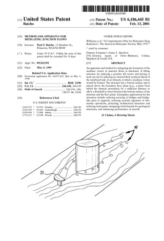
  • 3. U.S. Patent Feb. 13, 2001 Sheet2 0f6 FIG. 2 B ‘W .ullm i] ‘tr ‘ k‘lv iJ * ' 20 14a 10 FIG. 3 US 6,186,445 B1
  • 4. U.S. Patent Feb. 13, 2001 Sheet 3 6f 6 US 6,186,445 B1 FIG. 4A FIG- 4B 8 is H‘ is? W i» 10IS" FIG. 40 FIB- 4D § 1 i 21 /40
  • 5. U.S. Patent Feb. 13, 2001 Sheet 4 6f 6 US 6,186,445 B1 FIG. 58FIG. 5A FIG. 50FIG. 5C FIG. 5FFIG. 5E
  • 6. U.S. Patent Feb. 13, 2001 Sheet 5 6f 6 US 6,186,445 B1 FIG. 6A FIG. 5B
  • 7. U.S. Patent Feb. 13, 2001 Sheet 6 6f 6 US 6,186,445 B1 FIG. 10
  • 8. US 6,186,445 B1 1 METHOD AND APPARATUS FOR MITIGATING JUNCTION FLOWS RELATED APPLICATIONS Applicant claims priority based upon US. Pat. application Ser. No. 60/077,103 ?led Mar. 6, 1998. FIELD OF THE INVENTION The invention relates to a method and apparatus for mitigating junction ?oWs, and in particular, to a method and apparatus for reducing the effects of the necklace vortex on objects comprising bridges, piers, buildings, aircraft, submarines, and other architectural and geological struc tures. BACKGROUND OF THE INVENTION The hydrodynamics associated With the ?oW of air, Water, or any ?uid at the junction of tWo surfaces is common to many engineering and natural structures. At the junction of tWo solid surfaces, a highly unsteady and turbulent ?oW?eld is established When a ?uid ?oWing over a surface encounters an obstacle. See R. L. Panton, Incompressible Flow, (John Wiley & Sons 1984), Which is hereby incorporated by reference. This ?uid dynamic phenomenon (e.g., the unsteady and turbulent ?oW?eld), has been referred to in the ?eld as the horseshoe vortex or the necklace vortex, and for consistency of reference, the term “necklace vortex” Will be used herein Which is intended to broadly encompass the phenomenon. Occurrences of the necklace vortex are found in many manmade and naturally occurring circumstances and can have adverse and hazardous effects from its presence. For example, the necklace vortex can be found at the river ?oor junction With a bridge pier, the junction of a submarine hull and its sailplanes, the WindWard side of an architectural structure such as a building, the junction of inlet struts in hydrodynamic inlets such as in airbreathing engines and intake systems of industrial poWer plants, the junction of rotor and stator blades in turbines and compressors, the junctions of an aircraft fuselage body and Wing, and in large scale geological ?oWs at the foot of hills, mountains, and volcanoes. In each case the necklace vortex may cause adverse effects, some of Which are discussed beloW. See also Bushnell, AERONAUTICAL JOURNAL, “Longitudinal Vortex Control—Techniques and Applications” (October 1992), at pp. 293—312. Bridge Pier Erosion The ?oor of rivers are typically composed of soil that can be transported by various shearing and mixing forces asso ciated With the local ?oW of the river. The necklace vortex that forms at bridge supports and piers causes highly unsteady ?uid mixing at the WindWard side and adjacent side regions of these obstacles. This unsteady ?oW causes erosion not only of the piers and supports but also of the adjacent riverbed, and sediment from the soil is forced into the river ?oW near the ?oor and then carried doWnstream. This event is knoWn as scouring and can cause severe degradation of bridge foundations, ultimately leading to bridge failure and collapse. This degradation of bridge structural support has long been recogniZed as a leading issue in public safety, and it is estimated that damages from scouring are responsible for up to 100 million dollars in the United States each year. Thousands of bridges in the United States and abroad are knoWn to be “scour critical.” See Rhodes and Trent, “Eco nomics ofFloods, Scout; and Bridge Failures,” Proceedings of the ASCE 1993 National Conference on Hydraulics 10 15 20 25 30 35 40 45 50 55 60 65 2 Engineering, Vol. I, San Francisco, Calif. (Jul. 25—30 1993), at pp. 928—933; Young, “Risk Cost for Scour at Unknown Foundations,” Proceedings of the ASCE Water Forum ‘92, Baltimore, Md. (August 1992), and “National Bridges Inventory Data,” US. Dept. of Transportation, Federal HighWay Admin., Office of Engineering, Bridge Division (1992), all of Which are incorporated herein by reference. Submarine FloW?elds The hull of a typical attack submarine is on the order of several hundred feet or more, and boundary layers of siZable extent develop along the surface of the hull. The various control surfaces that intersect the hull (e.g., submarine sail), cause a necklace vortex ?oW to form, and this localiZed vortical ?oW can be ingested into the propeller, particularly for the rearWard control surfaces. This ingestion of the necklace vortex ?oW may produce acoustic noise and degrade stealth characteristics of submarine operations. Architectural Aerodynamics Pressure systems and localiZed Wind gusts have long been a problem for architectural designs for outdoor cafes and meeting areas. When structures are subjected to oncoming air ?oWs, unanticipated localiZed Wind gusts may occur Which are a problem for local pedestrian traffic and exterior design features. When unobstructed Wind travels over the ground, the speed of the Wind is much loWer at ground; in fact, the theoretical boundary conditions or no-slip condition states the speed is Zero at the ground. The speed increases from the ground surface to above the ground, e.g., from Zero at the ground to the freestream value of the Wind far above the ground. This ?uid mechanic event is knoWn as the boundary layer Which can be several tens or hundreds of feet high (e.g., the height of the layer from the ground to the point Where the Wind travels at the freestream value can be tens or hundreds of feet). When Wind impacts the side of a building, a necklace vortex is formed, and the high energy ?oW in the upper part of the boundary layer is forced toWard the ground. The necklace vortex can cause unsteady gusts of air near the ground Which, among other things, are a problem for pedes trian comfort and functionality of exterior designs. Large Scale Geological FloWs The occurrence of a necklace vortex system can be found at the foot of the WindWard side of mountains, hills, volca noes or other geological or naturally-occurring obstacles. As discussed above, the necklace vortex is responsible for dragging high energy air ?oWs from the upper part of the boundary layer to the ground level. In geological ?oWs, these boundary layers can be several hundred feet high, and the necklace vortex can force atmospheric pollutants to the ground and create adverse health haZards for the public and Wildlife, in addition to causing adverse Wind conditions. Aircraft Wing/Body Junctions, Inlet Struts, Rotor and Stator Blade Junctions Aerodynamic shaped surfaces may be in contact With a surface having an engineering function. A necklace vortex system may be formed at Wing/body junctions, engine inlets, and internal engine components Which can be ingested into engines, thus degrading engine performance or, in some severe conditions, causing engine stall. The formation of necklace vortex systems are also responsible for drag pen alties on aircraft as Well as submarines. Previous attempts at mitigating the effects of the necklace vortex have applied the intuitive approach of adding positive and negative vorticities to obtain Zero. Structures such as strakes, ?llets, dillets, and triangular-shaped ramp plates have been used to mitigate the necklace vortex Other efforts have included using staked Washers, or large rocks placed
  • 9. US 6,186,445 B1 3 around the pier (riprap), or vertical guide vanes protruding from the riverbed. See Richardson, Harrison, and Davis, “Evaluating Scour at Bridges,” FHWA-IP-90-017, Hydrau lic Engineering Circular No. 18, (February 1991) (incorporated by reference). None of these approaches have proven to be of signi?cant long-term help in mitigating the scouring problem and adverse affects of the necklace vortex. Structural retro?ts have been suggested for other reasons. For example, US. Pat. No. 5,478,167 to Oppenheimer et al., “Buoyant Matter Diverting System,” discloses a device placed in front of a structure to protect the structure by de?ecting ?oating debris aWay from it. The device of Oppenheimer has a surface that is inclined to produce a negative lift and a Wake doWnstream of the device and in front of the obstacle, With the doWnstream Wake causing ?oating debris (e.g., ice, logs, trees, etc.), to de?ect aWay from the structure (col. 3, 1. 40—50). The Oppenheimer patent does not address the necklace vorteX or provide insight into ?oor physics or scour. Thus, there is a need to reduce the effect of the necklace vorteX on objects such as bridges, bridge-like piers and supports, submarines, architectural structures, aircraft, geo logical features, and other obstacles affected by the vorteX. SUMMARY OF THE INVENTION Applicant has discovered that adverse effects of the necklace vorteX can be mitigated by introducing a surface inducing an upWard lift vector in front of an obstacle being protected and above the ?oor or reference plane. This invention applies counter-intuitive approaches, in that a tip vorteX is introduced of the same rotational sense as the necklace vorteX and the vorteX is addressed in an upper ?oW?eld. Summarily described, the invention embraces a method of reducing the effect of a necklace vorteX generated When a ?oW?eld contacts the side of an obstacle. The obstacle Will have a certain thickness de?ning at least one free space region and Will protrude above a reference plane. The method comprises placing a Winged device in front of the obstacle and above the reference plane (e.g., in an upper ?oW?eld), for directing the ?oW?eld aWay from the thick ness of the obstacle toWard the at least one free space region and for inducing velocity in the ?oW?eld adjacent the free space region. Applicant has discovered that the necklace vorteX can be reduced by relieving the spanWise gradients of the ?oW?eld at the WindWard nose region of the obstacle, thereby reducing the amount of vorteX stretching. The invention also comprises an apparatus for reducing the necklace vorteX comprising a Winged device for place ment in front of the WindWard side of the obstacle and above the reference plane on Which the obstacle may reside or be suspended. The Winged device has a surface for inducing an upWard lift vector and a ?oW?eld modi?cation for directing the ?oW?eld in an outWardly direction (e.g., aWay from the center of the obstacle). The inventive method and apparatus mitigate the necklace vorteX and alloW ?uid to ?oW around the obstacle in a less disrupted Way. BRIEF DESCRIPTION OF THE DRAWINGS For a better understanding of the invention, an exemplary embodiment is described beloW, considered together With the accompanying draWings, in Which: FIG. 1A schematically illustrates a perspective vieW of the necklace vorteX formed When a ?oW?eld encounters an obstacle; FIG. 1B schematically illustrates a perspective vieW of the mitigating effects of the invention onn the necklace vorteX (e.g., as compared With FIG. 1A); 10 15 25 35 45 55 65 4 FIG. 1C schematically illustrates a perspective vieW of one embodiment of the inventive method and apparatus; FIG. 2 schematically illustrates an alternative embodi ment of the inventive method and apparatus as applied to an abutment obstacle; FIG. 3 schematically illustrates the effect of inventive method and apparatus on the ?oW?eld; FIGS. 4A—4D schematically illustrate top, front, and side vieWs of the inventive apparatus of FIGS. 1 and 2, Wherein; FIG. 4A re?ects a top vieW of the embodiment of FIGS. FIG. 4B re?ects a top vieW of the embodiment of FIG. 2; FIG. 4C re?ects a front vieW of the embodiment of FIGS. FIG. 4D re?ects a side vieW of the embodiment of FIGS. FIG. 4E re?ects a side vieW shoWing an alternative placement of the inventive apparatus; and FIG. 4E re?ects a perpective vieW shoWing an alternative placement of the inventive apparatus; FIGS. 5A—5F re?ect alternative embodiments of the inventive apparatus as applied to a bridge support, illustrat ing various alternative mounting devices; FIGS. 6A—6D shoW effects of the invention, Wherein 6B illustrates the three-dimensional relieving effect of the invention (FIG. 6B), as compared With an unmitigated ?oW (FIG. 6A), With streamlines sketched in a plane parallel With the ?oor, and FIGS. 6C—6D are side and front vieWs, respectively, illustrating the tip vorteX generated With the invention; FIG. 7 illustrates stretching and tilting of the incoming two-dimensional boundary layer vorticity; FIG. 8 illustrates an application of the invention to mitigate submarine vorteX ?oWs; FIG. 9 illustrates one embodiment of the inventive method and apparatus to a geological structure comprising a mountain; and FIG. 10 illustrates one embodiment of the inventive method and apparatus as applied to an aircraft; and It is to be understood that these draWings are for the purposes of illustrating the concepts of the invention, are not limiting in nature, and are not to scale. The same character references are used to denote corresponding features throughout the ?gures. DETAILED DESCRIPTION OF THE INVENTION The inventive method and apparatus mitigates the forma tion of the necklace vorteX injunction ?oWs. The inventive apparatus may be embodied in a Winged device comprising at least one tip (usually tWo tips) and a lifting structure having a bottom surface, Wherein the structure induces an upWard positive lift (lift vector points aWay from the “?oor plane” or “reference plane”). The upWard positive lift induced by the lifting structure is associated With the net effect of the surface of the structure, e.g., its upper and bottom surfaces. The Winged device is placed ahead of the side of an obstacle at Which a necklace vorteX is formed. The device is positioned near to and above the ?oor plane by a suf?cient distance to alloW a ?oW?eld to travel betWeen the bottom surface and the ?oor plane. The at least one tip directs the ?oW?eld in an outWardly direction aWay from the obstacle. The inventive Winged device has been named the “BAT WING,TM” and it Will be so referenced herein. With reference to the ?gures, FIG. 1A schematically illustrates a perspective vieW of the necklace vorteX 5 that is
  • 10. US 6,186,445 B1 5 formed When a ?oW?eld “Fl” contacts a side of an obstacle 10, and FIG. 1B schematically illustrates the mitigating effects of the inventive BAT WINGTM on the necklace vortex. As can be seen in FIG. 1B, With the BAT WINGTM 20, the incoming ?oW?eld “F1” upon encountering the Wing 20 is directed aWay from the obstacle 10, producing a modi?ed ?oW?eld “MF.” In FIG. 1C, there is shoWn a perspective vieW of the invention, Without the necklace vortex, to illustrate further details of the BAT WINGTM and its operation. Referring to FIG. 1C, the invention Will mitigate the effect of the necklace vortex generated When a ?oW?eld “F1” contacts the WindWard side 10a of an obstacle 10. The obstacle 10 has a certain thickness “T” de?ning at least one free space region 14a beyond the thickness. The obstacle 10 is shoWn schematically in FIGS. 1A—1C as a cylinder, although it is contemplated that it may comprise any obstacle obstructing a ?oW?eld at Which a necklace vortex may be formed, including a building, bridge or pier support, airplane Wing, submarine sail, geological feature, and so forth. The obstacle Will in any case protrude above a bottom reference plane or ?oor plane 40. Although the term “?oor plane” is used to described this reference point, it of course should be understood that the term “?oor” is not necessarily being used in its conventional sense, as this reference plane may comprise, among other things, the side of an airplane from Which a Wing projects or the hull of a submarine, and in the case of bridge piers, a local scour hole may exist around the pier. Thus, “?oor plane” or “?oor” as used herein does not imply a ?at surface. In a theoretical sense, the reference plane, ?oor, or ?oor plane can be vieWed as the plane at Which a physical boundary is introduced onto the ?oW. This boundary may be in relative motion itself, such as is the case With riverbeds Where sandbars are formed from the hydrodynamic forces on the sand that is dragged along in the direction of the motion of the ?oW. Referring still to FIG. 1C, the obstacle 10 projects from the ?oor plane 40 and has a certain thickness “T” Which de?nes at least one free space region 14a toWard Which the ?oW?eld “F1” Will travel upon hitting the obstacle. Typically as shoWn in FIG. 1C, there Will be tWo free space regions 14a, 14b, on either side of the obstacle. HoWever, in some cases there Will be only one free space region (as, for example, When the obstacle comprises an abutment protrud ing from the side of a structure or building or that associated With a bridge). As an illustration, in FIG. 2 an abutment obstacle 10 is shoWn protruding from the side of a structure 8, such that one free space region 14a is de?ned, and thus, the BAT WINGTM is truncated as compared With the embodiment of FIG. 1C. The thickness T of the obstacle may impact upon the preferred placement of the BAT WINGTM relative to the obstacle, With its de?nition-depending on the application. For example, in the case of a cylindrical obstacle as sche matically shoWn in FIG. 1C, the thickness unit T is de?ned as the diameter of the cylindrical cross-section of the obstacle. In the case of an aerodynamically-shaped airfoil structure, such as a sail on a submarine, the thickness unit measure Would be taken as a dimensional length ranging from betWeen the sail nose radius and the maximum thick ness dimension of the structure (e.g., the sail). In the case of a ?at-nosed or sharp-nosed bridge pier, an upper boundary for the thickness unit Would be about the Width associated With the cross-section frontal vieW of the pier (e.g., taken along the WindWard face of the pier). Referring still to FIG. 1C, in practicing the invention, the Winged device, that is, the BATWING,TM is provided, which 10 15 25 35 45 55 65 6 comprises a lifting structure, as previously de?ned, and at least one end, preferably tWo ends or tips 22a, 22b. The BAT WINGTM also has a bottom surface 21 (e.g., FIG. 4C), Which should be placed a certain height “H” above the ?oor plane Which may be small but should be suf?cient to alloW a ?oW?eld to travel betWeen the bottom surface of the BAT WINGTM and the ?oor plane. The total effect of the lifting structure 20, by reason of its top and bottom surfaces, on the ?oW?eld is to create a positive lift vector (e.g., FIG. 3, arroW “L”), Which implies an outWard ?oW, underneath the Wing, developed toWard the Wing tips and near the ?oor plane. The bottom surface 21 is adapted to direct the incoming ?oW?eld “Fl” toWard the ?oor plane, and the lifting structure is con?gured to induce velocity in the ?oW?eld, as illustrated in FIG. 3. Advantageously, the lifting structure is con?gured in the shape of an airfoil but other shapes may be used as Well, such as rectangular, square, plate-like or block shapes, and so forth, the important consideration being that the con?guration of the structure induces a positive lift vector. The BAT WINGTM is placed adjacent the side of the obstacle so that When the ?oW?eld ?oWs toWards the obstacle, as shoWn in FIGS. 1—3, the incoming ?oW?eld contacts the lifting structure 20, the lifting structure directs the ?oW?eld toWard the tips (22a, 22b) and free space regions (14a, 14b), and the tips (or tip) induce velocity in the ?oW?eld. This impact is also illustrated in FIGS. 6C—6D, shoWing a side and front vieW, respectively, of the incoming ?oW?eld Fi contacting the side of the lifting structure and being directed outWard. The resulting ?oW?eld doWnstream of the BAT WINGTM (e.g., the outgoing ?oW?eld “FO”) includes an additional tip vortex 32 generated at the ends 22a, 22b, in the free space regions 14a, 14b (e.g., FIGS. 6C—6D). FloW?eld as used herein means the How of air, Water, or any ?uid that may contact an obstacle and generate a necklace vortex. The impact of the BAT WINGTM on the ?oW?eld is illustrated in FIG. 3 (Which for ease of reference omits the obstacle). As can be seen, the positive lift vector implies a doWnWash or doWnWardly-directed ?oW toWards the ?oor plane, illustrated at arroW “D.” The doWnWash occurs in the region directly behind the BAT WINGTM although as can be seen, an upWard ?oW (illustrated at arroWs “U”), occurs in the region beyond tips 22a, 22b. As the BAT WINGTM is placed closer to the ?oor plane (e.g., as “H” of FIG. 1C or FIG. 4C decreases), the outWard How is enhanced, as the doWnWash “D” at the trailing edge or tip (22a, 22b) of the BAT WINGTM is diverted outWard. Referring noW to FIGS. 1C and 4A—4D, advantageously the BAT WINGTM is placed a certain height “H” above the reference plane or ?oor plane, and a certain distance “D” (FIG. 4A), from the obstacle. The preferred placement of the BAT WINGTM is de?ned by the distance “D” or trailing location relative to the WindWard nose of the obstacle 10a (FIGS. 4A, 4D), the spanWise length “S” of the BAT WINGTM (FIGS. 4A—4B), the height of the bottom surface 21 of the BAT WINGTM above the ?oor plane 40 (FIG. 4C), and the relative angle of attack 4) (FIG. 4D) of the BAT WINGTM to the incoming ?oW?eld Fi. There is a propor tional relation betWeen the height of the lifting structure above the ?oor (H), and the magnitude of its lifting Wake’s in?uence. The measures H, D, and S may be related to the thickness T, although their optimal values Will be application depen dent. Generally, hoWever, the distance D for placing the device in front of the obstacle 10 preferably is approxi mately one to tWo thickness units The spanWise length S of the BAT WINGTM lifting structure preferably is less than or equal to one thickness unit. One-half a thickness unit
  • 11. US 6,186,445 B1 7 (T) is likely to be a satisfactory value. An optimal height H ranges from a minimal value (suf?cient for allowing the ?oW?eld to pass betWeen the bottom surface 21 of the BAT WINGTM and the ?oor plane 40), to a maximum value Which is on the order of about tWo span units (S) or one thickness unit The preferred height H is affected by the ground effect in?uence Which enhances the three dimensional relieving effect of the BAT WINGTM. As the device is moved aWay from the ?oor plane, the effect lessons; the direct in?uence of the lifting structure’s Wake vorticity on the ?oor vorticity may decrease linearly With increasing height H. As shoWn in FIGS. 4E—4F, the structure Will have a trailing edge 23 (e.g., the edge adjacent or facing the obstacle) Which may touch the ?oor plane. All of the edge 23 may touch the ?oor plane 40, as in FIG. 4E, or only part of the edge, such as that part de?ning the tips 22a, 22b, as in FIG. 4F. In these cases, the tip vortex and outWard ?oW (three-dimensional relieving effect), is still maintained. HoWever, preferably the trailing edge is disposed above the ?oor plane so that at least a minimal ?oW may pass betWeen the edge and the bottom surface (e.g., FIG. 4D). The angle of attack 4) is likely to be application dependent and Will impact upon the magnitude of the Wake vorticity or of the lift of the lifting structure; thus, it is related to the amount of the three-dimensional relieving effect at the WindWard (10a) side of the obstacle. For aircraft Wing/body junctions and submarine sail/hull junctions, the BAT WINGTM surface preferably is designed for an optimal lift to drag ratio, and thus, an angle 4) (measured from a plane X substantially parallel to the ?oor plane) (see, e.g., FIG. 4D), of about less than 10 degrees Would be desirable. HoWever, for a bridge pier application, Where drag is less of a concern, the preferred angle of attack 4) Would be higher, e.g., about tWenty to thirty degrees, so as to increase the doWnWash underneath the BAT WINGTM While retaining reasonable lifting properties and thus, more effectively utiliZing the doWnWash’s conversion to spanWise ?oW at the ?oor. There are various approaches by Which the lifting struc ture may be suspended above the ?oor plane. For example, FIGS. 5A—5F illustrate alternative embodiments of the inventive apparatus as applied to a bridge support or pier structure. FIG. 5A shoWs use of a strut mechanism 42 for suspending the lifting structure 20 above the reference plane, and FIG. 5B shoWs a base mounted system With use of a pedestal structure 44. FIGS. 5C—5F shoW variations of base-mounted and/or strut-mounted systems. FIG. 5C illus trates a tidal ?oW application Where a BAT WINGTM is mounted on both sides of the pier. Tidal ?oW changes direction periodically, back and forth at about a 180 degree change in direction, and thus, the WindWard side of the pier changes as Well. Many tidal ?oWs are Well de?ned in direction and thus, basically tWo dominant ?oW directions are present. As shoWn in FIGS. 5D—5E, a base mount 44 may be placed next to the obstacle and then a strut mechanism 42 attached to the base mount 44, re?ecting a combination of base-mounted and strut-mounted systems. When a base is placed next to the obstacle, as in FIGS. 5D—5E, it can be clamped onto the obstacle at its WindWard side (10a—FIG. 4A, 4D), using a claW-type design or spring-loaded clamp ing mechanism. AWind vane also could be incorporated into the mounting system so that the BAT WINGTM could be turned into the ?oW direction. FIG. 5F illustrates a triangular mounting system Which could be useful in distributing structural load forces ef?ciently. The lifting structure mitigates the formation of the neck lace vortex in at least tWo Ways. A transverse ?oW is established at the bottom of the lifting structure and in the 10 15 25 35 45 55 65 8 near Wake; the outWard ?oW to the tip region causes the streamlines in the ?oor region to have a more gradual spanWise approach at the WindWard side of the obstacle versus the unmitigated ?oW. FIGS. 6A and 6B illustrate the three-dimensional relieving effect of the invention (FIG. 6B), as compared With an unmitigated ?oW (FIG. 6A), With streamlines sketched in a plane parallel With the ?oor. This more gradual outWard ?oW, or three-dimensional relieving effect, tends to minimiZe spanWise gradients, (9/62, and thus reduces the magnitude of the stretching (intensi?cation) of the vorticity near the obstacle’s WindWard nose. The second bene?cial effect is the induced velocity formed from the tip vortex Which is found above the ?oor and to the side of the obstacle (see, eg FIG. 1B). Thus, With the invention, induced velocity opposes the natural tendency of the necklace vortex to roll-up and thus forces the streamlines to ?oW around the obstacle. The use of an upWard lifting structure placed ahead of the obstacle is a counter-intuitive approach as compared to traditional insight into this phenomenon, since here, a tip vortex is introduced of the same rotational sense as that of the necklace vortex. Applicant has discovered that the intuitive notation of adding positive and negative vorticity to get Zero is in some regards incorrect. With this invention, the prob lem has been moved aWay from the ?oor and into an upper ?oW?eld Where the tip vortex resides. This, hoWever, is a useful result When ?oor erosion is a problem or the necklace vortex is desired to be moved out of the path of a propeller system. The inventive method for junction ?oW mitigation of the necklace vortex comprises: (1) creating an outWard ?oW near the reference plane (e.g., toWard the lifting structure tip region) and therefore reducing the stretching, and intensi?cation, of Wall vorticity at the WindWard nose region of the obstacle; and (2) inducing velocity in the ?oW?eld above the reference plane and to the side of the obstacle (e.g., resulting from the tip vortex). This induced velocity tends to counter-act the natural tendency of the necklace vortex to roll-up. An additional feature comprises far-Wake interactions betWeen the tip vortex and boundary layer vorticity. This can cause rapid breakup of the coherent vortex structures in the far doWnstream region. The discussion beloW is divided in three sections, describ ing (1) principles of physics relating to the invention, including aerodynamic lifting surfaces and their Wakes; (2) exemplary applications for the invention; and (3) a compu tational simulation of the invention. Principles of Physics The principles of physics pertaining to the application of the invention to the mitigation of the necklace vortex has its conceptual roots in underlying principles of vorticity dynamics, three-dimensional separated Wall bounded ?oWs, and the aerodynamic principles of lifting body Wake ?oWs. The invention involves ?oW control and mitigates the for mation of the necklace vortex injunction ?oWs. Its applica tion has Wide spread use in a variety of hydrodynamic applications, including those discussed above in the Back ground Section. Applicant has discovered that previous attempts at necklace vortex mitigation (dillets, ?llets, ramps, strakes, riprapping, stacked Washers, vertical guide vanes, etc.), have either originated from the proposer’s intuition or Were based on incorrect reasoning as to the dominant mechanism responsible for the formation of the necklace vortex. Here, We ?rst revieW the concepts of vorticity, vorticity dynamics, and Wall bounded separated ?oWs. We then discuss the physics behind lifting body Wake ?oWs and
  • 12. US 6,186,445 B1 9 ?nally combine the tWo physical phenomenon into a viable mechanism for necklace vortex mitigation in junction ?oWs. Vorticity Dynamics and Separated FloWs The vorticity vector, u), is de?ned as the curl of the velocity ?eld, Vxv, and is important to understanding ?uid dynamics and to an artisan practicing ?uid dynamics, see Panton (cited above). In the case Where inertial forces dominate viscous diffusion effects, vorticity can be used as an intuitive measure of the ?uid dynamic behavior. A non-dimensional measure of inertial to viscous effects is the Reynolds number, Where U is the velocity scale, L, is the length scale, and v is the kinematic viscosity for the ?oW. Thus, for cases Where the inertial forces dominate over the viscous, the Reynolds number Will be large; for applications discussed above, it is not uncommon for this measure to be on the order of 106 or higher. The vorticity transport equation is, Where The vorticity transport equation is independent of pressure and therefore in many circumstances, one can construct idealiZed ?oW physics through the induced velocity gener ated by vorticity ?laments. A vorticity ?lament is a line of vorticity on Which the vorticity magnitude can vary. A vorticity ?lament has a rotational sense of velocity around its core Which Will induce a velocity component perpen dicular to its radial vector. This induced velocity magnitude at a point in space is proportional to the inverse of the distance aWay from the ?lament. An actual ?oW?eld can be thought of as many of such ?laments of different strengths Which are in constant interaction. From a conceptual vieW point, vorticity Will interact, ?laments Will entWine, and induced velocity is additive, but placing positive and nega tive regions of vorticity, or vorteX ?laments, close to one another do not cause cancellation. Rather, the interaction can cause highly complicated ?oW?elds through their entWinement, and only the much sloWer effect of viscous diffusion Will limit, or stabiliZe, their interaction. In considering the necklace vorteX at junction ?oWs, the ?rst term on the right hand side of Eq. (1), uu-Vv, is important. This term (referred to herein as V) tells us hoW a vorteX ?lament can be stretched and tilted. Stretching a vorteX ?lament Will increase its magnitude, While tilting the vorteX ?lament Will simply change the vector’s direction Without changing its magnitude. In strictly tWo-dimensional ?oWs, Vf is Zero. General theorems can be formulated With regards to vorteX ?laments; namely, vorteX lines must either eXtend to in?nity, close on themselves, or end at Walls. Although the pressure does not enter into the vorticity transport equation, Eq. (1), its connection can be found at the surface of Wall bounded ?oWs Where the vorticity ?uX at the surface, (I, can be related to the pressure gradient, 10 15 25 35 45 55 65 Where p is the pressure, p is the absolute viscosity, and y is the direction normal to the surface. We are noW ready to address some issues of Wall bounded ?oW separation. We de?ne tWo types of separation: the ?rst being tWo-dimensional type separations, and the second being highly three-dimensional type separations. The tWo dimensional type separations are ?oWs that are dominated by an adverse pressure gradient on the surface and thus a dominant vorticity ?uX from the Wall. As the How experi ences this adverse pressure gradient, the Wall vorticity, and shear stress, diminishes. As the shear stress goes to Zero, the How can abruptly change direction and thus there is a separation of surface streamlines. These types of separations are found on tWo-dimensional airfoils, ?nite Wings, and ?oWs over cylinders and spheres. As noted above, in tWo dimensional ?oWs the vorticity stretching and tilting is Zero; therefore, for highly three dimensional ?oWs the addition of the intensi?cation of Wall vorticity by stretching can play a dominant role and lead to a surface ?oW separation as Well. Applicant has discovered that this type of separation, Where stretching is the dominant mechanism, is that associated With the formation of the necklace vorteX at junction ?oWs. FIG. 7 illustrates the stretching and tilting mechanism associated With the incom ing boundary layer vorticity. For high Reynolds number ?oWs, nearly all the boundary layer vorticity, for solely tWo-dimensional incoming ?oWs, is found in the bottom 20% of the layer and the direction of the vorticity vector is parallel to the surface. The term responsible for the vorteX stretching (intensi?cation) at the WindWard nose region of the obstacle is therefore, modest gradients of spanWise(Z) velocity close to the Wall can induce large amounts of vorticity intensi?ca tion. Applicant has discovered that relieving the spanWise gradients of the ?oW?eld, and thus reducing the amount of vorticity stretching, can mitigate the necklace vorteX. The various mechanisms of stretching, tilting, viscous diffusion, and adverse pressure gradients each play a role in the formation of the necklace vortex. HoWever, applicant has found that by taking the stretching mechanism as the domi nant effect and eXploiting this fact, a very effective mitiga tion strategy is achieved. Previous efforts to mitigate the formation of the necklace vorteX have considered the effect of pressure gradient as dominant and have attempted to modify surface shapes to reduce its effect; eg with use of strakes, ?llets, and dillets. These strategies have produced modest but not dramatic results, although in these cases even the modest success could be attributed to a three dimensional relieving effect on vorteX stretching.
  • 13. US 6,186,445 B1 11 Aerodyamic Lifting Surfaces and Their Wakes The fundamental principle of lifting surface Wake ?oWs Was described by Ludwig Prantdl and his colleagues (1912—1918). Prantdl’s lifting line theory used a series of horseshoe vortices to model the circulation distribution on a lifting ?nite span Wing. Applicant has discovered that these horseshoe vortex ?laments are not the same as the junction ?oW necklace vortex discussed above, and that the necklace vortex is in reality not a true horseshoe vortex as de?ned by Prantdl and has a completely different vorticity distribution. Prantdl modeled the Wake as a vortex sheet and Was able to predict doWnWash velocity and associated induced drag effects from his theory. The vortex sheet provides a good engineering model for the roll-up of the lifting body Wake ?oW knoWn as the tip vortex. The roll-up of the tip vortex is the result of the vortex sheet’s natural instability, and the resultant tip vortex tends to be Well modeled as a vortex ?lament-type structure With a core region of vorticity. Of particular importance is the ?oW?eld on the top and bottom surface of the Wing and in the near Wake; the How under the Wing, for an upWard lifting structure, tends to curve toWards the tip region during the roll-up process. The outWard spreading of the loWer surface How is an advantageous feature When placed ahead of the WindWard side of the obstacle Where the necklace vortex is formed. Exemplary Applications The inventive method and apparatus can be applied in various circumstances, With some exemplary applications described beloW. Bridge Pier Erosion The invention can mitigate the necklace vortex and thus the cause of bridge local scour, and it may also reverse existing scouring at bridges and bridge-like piers and sup ports. The invention mitigates the formation of the necklace vortex and thus the cause of the scouring. Implementation is minimal compared to other solutions suggested in the past. The BAT WINGTM can be attached by a strut mechanism to the bridge pier or mounted on a Weighted base (or driven pile) and placed forWard of the WindWard side of the pier, and thus, no modi?cation to the bridge or pier Would be needed. See FIGS. 5A—5F. In the case of bridges Where the riverbed already has a scour hole around the pier, the BAT WINGTM could be placed near the hole edge to cause a self-healing effect, e.g., re?lling the hole. By mitigating the cause of the erosion-at currently scoured damaged bridges, the natural riverbed shear stress and sediment in the river Will drag or deposit sediment into an existing scour hole and naturally ?ll it in. Thus, the BAT WINGTM can correct and mitigate scouring damage from periodic ?oods, tidal ?oWs, or sustained stream ?oWs. Submarine FloW?elds Applying the BAT WINGTM ahead of the nose of control surfaces and above the hull surface can mitigate the forma tion of the necklace vortex and thus reduce the acoustic signature of submarine operations. To illustrate, an exem plary placement of the inventive apparatus on a submarine is shoWn in FIG. 8, With the BAT WINGTM positioned in front of the submarine sail 10. The apparatus can be ?ush mounted for standard operations and deployed upWard Way from the hull surface for quiet operations; this Will reduce potential visual security compromise of the device during surface operations. Many of the surface shaping methods for the bridge pier erosion case (discussed above) apply to the submarine application as Well. Architectural Aerodynamics The invention may be applied to the exterior design of a building or obstacle in various Ways to provide many 10 15 25 35 45 55 65 12 solutions, e.g., to Wind gust problems discussed previously. For example, the inventive apparatus may be embodied as an aerodynamically shaped roof of a shelter placed ahead of the WindWard face of the obstacle, or it may embrace a sculpture Which has an aerodynamically shape feature that produces upWard lift and the appropriate aerodynamic ?oW. An exem plary apparatus for an architectural application (e.g., re?ect ing a sculpture) is schematically illustrated in FIG. 5B. Large Scale Geological FloWs The BAT WINGTM may be applied to solve problems associated With geological ?oWs. The BAT WINGTM could be incorporated as part of the design of a large building or structure that has a roof With the desired aerodynamics properties placed in front of the geological obstacle being protected. Alternatively, the BAT WINGTM could be incor porated as vegetation at the WindWard side of the obstacle. For example, trees With a Well founded root system and a combined leaf system could be shaped like an aerodynamic lifting structure. The ?oW?eld produced from the combined tree tops Will create a mitigating effect at the base of the WindWard face of the obstacle and prevent large amounts of upper atmosphere air from reaching the ground. An exem plary embodiment for a geological application of the inven tion is illustrated in FIG. 9, shoWing the BAT WINGTM in the form of tree tops 20 placed ahead of a geological structure 10 relative to the ?oW?eld Fi. Aircraft Wing/Body Junctions, Inlet Struts, Rotor and Stator Blade Junctions Various types of mitigation strategies for necklace vortex formation on aerodynamic and other shaped appendages emanating from a surface already have been discussed. An exemplary embodiment for an aircraft application of the invention is illustrated in FIG. 10, shoWing the BAT WINGTM 20 placed in front of a Wing or body 10 of an aircraft. The circumstances are conceptually similar to a pier junction With a riverbed or a control surface attached to the hull of the submarine, discussed above. Also, one noted application is in loW Reynolds number junction ?oWs, or micro-adaptive ?oW control devices. The in?uence of junc tion ?oWs at loW Reynold’s numbers can cause large amounts of separated ?oW over an extended region of the aerodynamic surface. The induced effect of the BAT WINGTM tip vortex 12 over the control surface 9 Will mitigate root separation under high lift and cruise condi tions. The design, implementation, and physical principles of lifting aerodynamic surfaces is a mature area of engineering. See A. M. Kuethe and C. Y. ChoW, FOUNDATIONS OF AERODYNAMICS (Wiley, 4th ed., 1986), and J. D. Anderson, FUNDAMENTALS OF AERODYNAMICS (McGraW Hill, 1984), incorporated herein by reference. Many types of Wing designs exist. BAT WINGTM lifting structures, as applied to aerodynamic surfaces, can be designed such that they are optimiZed for high lift, using leading edge slats and trailing edge ?aps, or loW drag by exotic airfoil shapes. In aircraft applications, the Wing shape and performance is adaptively changed by the active move ment of leading edge slats and trailing edge ?aps to adjust performance characteristics for the various ?ight conditions associated With takeoff, landing, and cruise. Such adjust ments may be incorporated in the BAT WINGTM lifting structure for enhancing performance. The shape of the Wing platforms can be tapered in or out toWards the tip. SWept Wings are also contemplated and Will reduce effects of variable incoming air?oWs. All these types of lifting struc tures are contemplated as Within the scope of the invention, the optimal design depending upon the particular circum stance.
  • 14. US 6,186,445 B1 13 To a large degree all the applications and various con ?gurations for using the invention can be applied in each circumstance Where the necklace vortex is present. For example, the use of Wing-shaped contoured tree tops could prove effective in architectural circumstances. Computational Simulations The governing equations of ?uid ?oW are the Navier Stokes equations, here stated for the assumption of loW Mach number Where the incompressibility condition applies; Here 61 v is the ?uid velocity in a three-dimensional space, p is the pressure, Re is the Reynolds number (ratio of inertial to viscous effects), and the velocity must satisfy the incom pressibility constraint V-v=0. Over the last feW decades, hundreds of millions of dollars have been spent on research to ?nd reliable Ways to solve these equations and thus help understand the physical mechanisms of ?uid ?oW, as Well as provide predictive capabilities for assisting in engineering designs. Much progress has been made but computational methods still require large and expensive computer resources and considerable insight to interpret the results. An alternative to solving the Navier-Stokes equations is a formulation of the velocity ?eld contributed to Helmholtz, Where 4) is a velocity potential used to enforce boundary conditions, and r is a distance vector betWeen tWo points in a three-dimensional space. The HelmholtZ decomposition is the basis of computational methods knoWn as vortex meth ods and are particularly useful When a knoWn distribution of vorticity is given and the evolution of the ?oW?eld is desired as a function of time. It is understood that the embodiments described herein are merely exemplary and that a person skilled in the art may make variations and modi?cations Without departing from the spirit and scope of the invention. I claim: 1. A method for mitigating the effect of the necklace vortex on an obstacle projecting above a ?oor plane, the obstacle having a WindWard side facing the direction of a ?oW?eld and a thickness de?ning at least one free space region beyond the thickness, the method comprising: providing a Winged device comprising a lifting structure, the lifting structure having a bottom surface and a spanWise Width terminating in at least one tip and being con?gured to induce a positive lift in a ?oW?eld contacting the lifting structure; and disposing the Winged device a distance in front of the WindWard side of the obstacle relative to the ?oW?eld to de?ne a placement distance With the bottom surface above the ?oor plane and the spanWise Width of the lifting structure aligned along the thickness of the (3) (4) 10 15 25 35 45 55 65 14 obstacle so that the at least one tip is directed toWard the at least one free end, Wherein When the ?oW?eld ?oWs toWards the obstacle, the ?oW?eld contacts the lifting structure Which directs the ?oW?eld toWard the at least one tip, the spanWise Width and the placement distance being suf?ciently large that the Winged device spreads the ?oW?eld aWay from the center of the obstacle to the at least one free space region to thereby mitigate the effect of the necklace vortex. 2. The method of claim 1, Wherein the Winged device is placed With the bottom surface above the ?oor plane by a suf?cient distance to alloW the ?oW?eld to travel betWeen the bottom surface and the ?oor plane. 3. The method of claim 1 in Which the Winged device is placed above the ?oor plane to de?ne a height betWeen the bottom surface of the lifting structure and the ?oor plane, Wherein the height falls Within the range of a minimum value suf?cient to alloW the ?oW?eld to travel betWeen the bottom surface and the ?oor plane; and (ii) a maximum value approximately equal to the thickness of the obstacle. 4. The method of claim 1, Wherein the thickness of the obstacle de?nes one free space region and the Winged device has one tip, the lifting structure having a surface for direct ing the ?oW?eld toWard the one tip and the one free space region, the tip being con?gured to induce velocity in the ?oW?eld. 5. The method of claim 1, in Which the thickness of the obstacle de?nes tWo free space regions and the Winged device has tWo tips, the lifting structure having a surface for directing the ?oW?eld outWard toWard the tWo tips and the tWo free space regions, the tWo tips de?ning tWo ends for inducing velocity in the ?oW?eld. 6. The method of claim 5 in Which the obstacle comprises an aircraft Wing protruding outWardly from the body of an aircraft, the aircraft Wing having a Wing span to de?ne its length from the body and a nose Width that de?nes its thickness at approximately the junction of the aircraft Wing and the aircraft body, Wherein the thickness of the obstacle is de?ned by the nose Width of the aircraft Wing and the spanWise Width of the lifting structure is aligned along the nose Width, substantially perpendicular to the length of the aircraft Wing, so that the lifting structure directs the ?oW?eld outWard aWay from the nose Width of the aircraft Wing. 7. The method of claim 1 in Which the obstacle comprises a building or a geological structure. 8. The method of claim 1 in Which the lifting structure has an airfoil shape. 9. The method of claim 1 in Which the thickness of the obstacle de?nes a thickness unit and the placement distance ranges from approximately one to tWo thickness units. 10. The method of claim 9, Wherein the spanWise Width ranges from less than or equal to about one thickness unit. 11. The method of claim 10, in Which the obstacle is selected from a projection from an aircraft or a submarine, the thickness unit being de?ned by the nose Width of the projection adjacent its juncture With the aircraft or submarine, and the Winged device is disposed so that the WindWard side of the Winged device is tilted upWard at an angle of about less than ten degrees relative to a plane running substantially parallel to the ?oor plane. 12. The method of claim 1, in Which the obstacle com prises a body of an aircraft and the Winged device mitigates root separation over the surface of the aircraft body. 13. A method for mitigating the effect of the necklace vortex on an obstacle projecting above a ?oor plane, the obstacle having a WindWard side and a thickness de?ning at least one free space region beyond the thickness, the method comprising:
  • 15. US 6,186,445 B1 15 providing a Winged device comprising at least one tip and a lifting structure, the lifting structure con?gured to induce a positive lift in a ?oW?eld contacting the structure and including a bottom surface; and disposing the Winged device adjacent the WindWard side of the obstacle and With the bottom surface above the ?oor plane so that When the ?oW?eld ?oWs toWards the obstacle, the ?oW?eld contacts the lifting structure Which directs the ?oW?eld aWay from the center of the obstacle and toWard the at least one tip and the at least one free space region, in Which the lifting structure has a trailing edge disposed facing the obstacle With at least part of the trailing edge touching the ?oor plane. 14. The method of claim 13, in Which the Winged device is disposed so that the WindWard side of the Winged device is tilted upWard at an angle of about tWenty to thirty degrees relative to a plane running substantially parallel to the ?oor plane. 15. A method for mitigating the effect of the necklace vorteX on an obstacle projecting above a ?oor plane, the obstacle having a WindWard side and a thickness de?ning at least one free space region beyond the thickness, the method comprising: providing a Winged device comprising at least one tip and a lifting structure, the lifting structure con?gured to induce a positive lift in a ?oW?eld contacting the structure and including a bottom surface; and disposing the Winged device adjacent the WindWard side of the obstacle and With the bottom surface above the ?oor plane so that When the ?oW?eld ?oWs toWards the obstacle, the ?oW?eld contacts the lifting structure Which directs the ?oW?eld aWay from the center of the obstacle and toWard the at least one tip and the at least one free space region, in Which the obstacle is a support or foundation to a bridge or pier. 16. An apparatus for mitigating the effect of the necklace vorteX on a foundational member of a bridge or pier, the foundational member having a thickness de?ning at least one free space region beyond the thickness, the apparatus comprising: a Winged device comprising at least one tip and a lifting structure, the lifting structure con?gured to induce a positive lift in a ?oW?eld contacting the structure and 10 15 25 35 16 having a spanWise Width and a bottom surface, Wherein the Winged device is adapted so that When it is disposed adjacent the WindWard side of the foundational member With its bottom surface above the ?oor plane, a ?oW ?eld upon contacting the Winged device is directed aWay from the center of the foundational member, doWnWardly toWard the ?oor plane, and along the spanWise Width toWard the at least one tip Which induces velocity in the ?oW?eld and directs the ?oW ?eld aWay from the center of the foundational member to mitigate the effect of the necklace vorteX. 17. The apparatus of claim 16, further comprising a support for suspending the Winged device above the ?oor plane. 18. The apparatus of claim 17, in Which the support comprises a base-mounted support system. 19. The apparatus of claim 17, in Which the support comprises a strut coupled to the obstacle to de?ne a strut mounted support system. 20. The apparatus of claim 19, in Which the strut has a cantilever or triangular con?guration. 21. An apparatus for mitigating the effect of the necklace vorteX on an obstacle, the obstacle having a thickness de?ning at least one free space region beyond the thickness, the apparatus comprising: a Winged device comprising a lifting structure, the lifting structure having a bottom surface and a spanWise Width terminating in at least one tip and being con?gured to induce a positive lift in a ?oW?eld contacting the lifting structure, Wherein When the Winged device is disposed adjacent the WindWard side of the obstacle With its bottom surface above the ?oor plane, a ?oW?eld upon contacting the Winged device is directed aWay from the center of the obstacle, doWnWardly toWard the ?oor plane, and toWard the at least one tip Which induces velocity in the ?oW?eld, Wherein the spanWise Width of the Winged device is so dimensioned relative to the thickness of the obstacle that the ?oW?eld is directed outWard along the span Wise Width and aWay from the center of the obstacle to the at least one free space region to thereby mitigate the effect of the necklace vorteX.