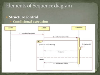
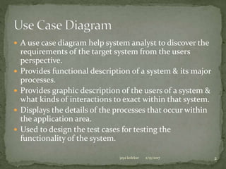
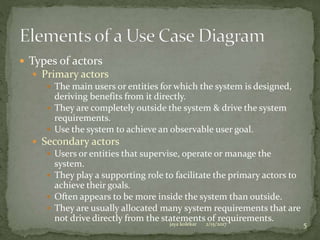
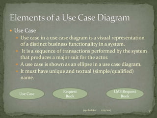
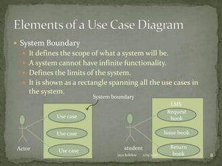
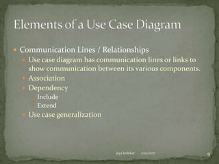
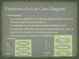
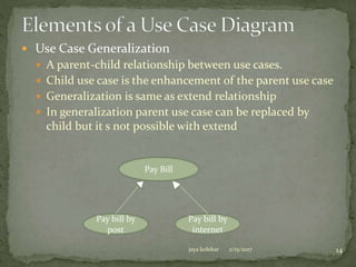
A use case diagram helps system analysts discover system requirements from the user's perspective. It provides a graphic description of users and their interactions with a system. A use case diagram contains actors, use cases, and relationships between them. It shows the system boundary and can be used to design test cases.


![ Simple & block iteration
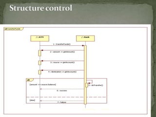
Sometimes a task is to be performed repeatedly, then in
sequence diagram such task is represented by a name
preceded by an asterisk “ * “.
A repetition or loop within a sequence diagram is depicted as
a rectangle.
C : Cashier B : Bill
Customer
Prepare bill <<create>>
B : Bill
Buy product
[all product added]
Get product details
Add product
Update quantity
Calculate total amountDisplay total
loop
2/15/2017jaya kolekar 27](https://image.slidesharecdn.com/basicbehavioralmodelingchapter3-170316071003/85/Basic-behavioral-modeling-chapter-3-of-OMD-27-320.jpg)