
Recommended
Recommended
More Related Content
What's hot
What's hot (20)
Similar to Aseptic Loosening In TKA: Causes, Diagnosis, Imaging
Similar to Aseptic Loosening In TKA: Causes, Diagnosis, Imaging (20)
Recently uploaded
Recently uploaded (20)
Aseptic Loosening In TKA: Causes, Diagnosis, Imaging
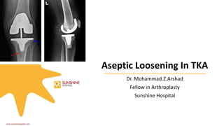
- 1. Aseptic Loosening In TKA Dr. Mohammad.Z.Arshad Fellow in Arthroplasty Sunshine Hospital
- 2. OVERVIEW • Introduction • Causes of failure • History • Definition • Pathogenesis • Diagnosis • Modern Knee Society Radiographic Evaluation System • Treatment • Principles Of Revision TKA
- 3. INTRODUCTION • TKA by almost any measure is extremely successful at relieving pain and restoring function for patients with knee arthritis. • General studies show the incidence of revision for any reason to be 3% or less at 5 and 10 yrs.
- 4. Causes Of Knee Arthroplasty Failure • Infection • Aseptic loosening and wear-Sharkey et al highlighted aseptic loosening as the most common cause, at 39.9% of all revision TKAs. • Arthrofibrosis • Instability
- 5. History • Harris et al ascribed the localized bone resorption, and subsequent component loosening, seen in artificial joints to “cement disease” . • They felt that particles of cement were somehow related to the loss of bone seen around artificial joints. • This idea lead to cementless implants, which are commonly used in hip arthroplasty today. • However, when cementless implants showed similar patterns of bone loss and loosening, it became clear that the explanation was far more complicated.
- 6. History • Schmalzried et al in 1992 showed that small polyethylene particles were present in macrophages in the periprosthetic region, particularly at the prosthesis/cement and bone interface. • The implication was that all areas of the prosthesis that could be exposed to joint fluid were susceptible to osteoclast-mediated bone resorption.
- 7. Definition • Aseptic loosening refers to the failure of joint prostheses without the presence of mechanical cause or infection. It is often associated with osteolysis (bone resorption) and an inflammatory cellular response within the joint.
- 8. Causes • Implant factors - fixation type, implant design, use of constraint, and wear debris from metal, cement, or polyethylene. • Surgical factors - joint malalignment and ligamentous imbalance, surgical and cement technique. • Patient factors - osteoporosis, stress shielding, high BMI.
- 9. Pathogenesis • Osteolysis represents a histiocytic response to wear debris. Steps in the process include:- • Particulate debris formation • Macrophage activated osteolysis • Prosthesis micromotion • Particulate debris dissemination
- 10. Step 1: Particulate Debris Formation Wear leads to particulate debris formation Types of wear:- • Adhesive wear-microscopically PE sticks to prosthesis and debris gets pulled off • Abrasive wear- cheese grater effect of prosthesis scraping off particles • Third body wear- particles in joint space cause abrasion and wear • Volumetric wear- main determinant of number of particles created • Linear wear- is measured by the distance the prosthesis has penetrated into the liner
- 11. Step 2: Macrophage Activated Osteoclastogenesis and Osteolysis • macrophage releases osteolytic factors(cytokines) including - TNF-alpha - TGF-beta - osteoclast activating factor - oxide radicals - hydrogen peroxide - acid phosphatase - interleukins (Il-1, IL-6) - prostaglandins - Osteoclast activation and osteolysis • Increase of TNF- alpha increases RANK • Increase of VEGF with UHMWPE enhances RANK and RANKL activation • An increase in production of RANK and RANKL gene transcripts leads to osteolysis Macrophage activation macrophage recruitment Increase TNF-alpha increases RANK RANKL mediated bone resorption Osteolysis
- 12. Step 3: Prosthesis Micromotion • Osteolysis surrounding the prosthesis leads to micromotion o micromotion leads to increase particle wear and further prosthesis loosening o N-telopeptide urine level is a marker for bone turnover and are elevated in osteolysis
- 13. Step 4: Debris Dissemination • Increase in hydrostatic pressure leads to dissemination of debris into effective joint space. o increased hydrostatic pressure is the result of inflammatory response o dissemination of debris into effective joint space further propagates osteolysis.
- 14. Small particles Inflammatory response Particles <1um phagocytosed by macrophages Stimulate Osteoclasts Resorb bone around prosthesis Process + other factors Loosening of implant
- 15. Factors • Factors affecting wear rate of polyethylene in TKA - patients < 50 year old implying demand or activity level of patient - motion between modular tibial insert and metal tray (i.e., backside wear) - Sterilization method (gamma radiation should be followed by remelting in o2 free environment destroying remaining free radicals) - manufacturing method (machining > compression molding) - thickness < 6mm more stress on component more wear (Barret et al recommends above 8 to 10 poly)
- 16. Factors • Presence of third-body debris- roughness of femoral component counterface • Alignment and stability of the TKA -malalignment causes asymmetric loading causes early loosening -more frequent with varus rather than valgus malalignment
- 17. Collier et al found that • Failure to correct hip-knee-ankle alignment at TKA will continue the pathologic wear state. • Placing a TKA in 5 degrees more varus could lead to 0.11 to 0.14 mm/year more polyethylene wear. • Less varus alignment decreased the amount of medial tibial polyethylene wear 2 to 3 times. • The ideal alignment after TKA would have a mechanical axis of zero. Malalignment Increased Wear Aseptic Loosening
- 18. Diagnosis • Symptoms o pain: -localized to the tissues around the loose components o swelling: -due to irritation of loose component causing proliferation of synovium & increased fluid production o knocking of knees • Aggravating factors -weightbearing -often activity related
- 19. Diagnosis • Physical examination o May have minimal pain with ROM o Increased pain with weight bearing o May or may not be any instability o Presence of clinical malalignment is nearly pathognomonic • Serum labs o ESR normal o CRP normal o Any elevation should prompt aspiration of the knee • Excluding infection is very critical before a thorough evaluation of aseptic loosening
- 20. Imaging • AP X-Rays - tibial osteolysis readily visible on AP - femoral osteolysis may be difficult to detect on AP as lesions are typically located in posterior condyles and are obscured by the femoral component • Oblique X-Rays - often more helpful for identifying femoral osteolysis. • Findings - radiolucent line around implant or cement strongly suggestive - change in position of the implant -varus or valgus subsidence of tibial component
- 21. Imaging • Radiographically, fixation of cemented TKA may be assessed by radiolucent lines (RLLs), defined as radiolucent intervals between either the implant and the cement, or the cement and the underlying bone. • A few previous studies suggest that the presence of a nonprogressive RLL is not predictive of aseptic failure.
- 22. Imaging • However, Kajetanek et al in their study found a positive correlation between the presence of an RLL and surgical revision for aseptic loosening.
- 23. Modern Knee Society Radiographic Evaluation System • A modern system was developed, approved by the Knee Society members, which ensured proper radiographic documentation of coronal and sagittal implant alignment, fixation interface integrity with respect to radiolucent lines and osteolysis to document precise deficiency locations. • The documentation of lucent lines should be graded as “partial” or “complete” with respect to the zone denoted on the schematic images and regions of osteolysis should be documented in millimetres in the zone locations. • This evaluation system remains descriptive rather than predictive or prognostic in its current scope and form.
- 24. MKSRES Implant Zone Classification : Tibial Component • Tibial Component AP View: • Zone 1: medial baseplate • Zone 2: lateral baseplate • Zone 3: central keel/stem region (“M” and “L” designate the respective regions of the central keel) • Zone 4: Revision TKA Stem Extension (“M” and “L” designate the respective regions of the stem extension) • Zone 5: inferior aspect of tibial keel/stem Fig. 3. (A) Coronal radiographic schematic of keeled and two-peg implants with zones for documentation of radiolucent lines and osteolysis.
- 25. MKSRES Implant Zone Classification : Tibial Component • Tibial Component Lateral View: • Zone 1: anterior baseplate • Zone 2: posterior baseplate • Zone 3: central keel/stem/peg fixation region (“A” and “P” designate the respective regions of the central keel) • Zone 4: Revision TKA Stem Extension (“A” and “P” designate the respective regions of the stem extension) • • Zone 5: inferior aspect of tibial keel/stem Fig. 3. (B) sagittal radiographic schematic of keeled and two-peg implants with zones for documentation of radiolucent lines and osteolysis.
- 26. MKSRES Implant Zone Classification : Femoral Component • Femoral Component Lateral and AP View • Zone 1: anterior flange • Zone 2: posterior flange • Zone 3: central box/peg/distal fixation region (“A” and “P” designate the respective chamfers if visible) • Zone 4: Revision TKA Stem Extension (“M” and “L” designate the respective regions of the stem extension on the AP view; “A” and “P” designate the respective regions of the stem extension on the lateral view Fig. 4. (C) Coronal and (D) sagittal radiographic schematic of revision femoral implants that have stem extensions with zones for documentation of radiolucent lines and osteolysis. Radiolucent lines should be denoted and documented as “partial” or “complete” and osteolysis documented in millimeters. (C) Sagittal plane radiographic schematic of femoral implant with zones denoted for documentation radiolucent lines and osteolysis
- 27. MKSRES Implant Zone Classification : Patellar Component • Patella Component Patellofemoral View: • Zone 1: medial • Zone 2: lateral • Zone 3: central peg/baseplate region (“M” and “L” designate the respective regions on the merchant view, whereas “S” and “I” designate the superior and inferior regions on the lateral view) • Patella bone thickness is measured and noted. Fig. 5. Patellofemoral radiographic view schematic denoting patella bone thickness, measured in millimeters. . (D) Patellofemoral view radiographic schematic of multi- or single peg patella implant with zones denoted for documentation radiolucent lines and osteolysis. Radiolucent lines should be denoted and documented as “partial” or “complete” and osteolysis documented in millimeters.
- 28. IMAGING • CT Scan & MRI - viable options for assessing larger osteolytic lesions to aid in preoperative planning • Tc Bone scan • Differential - Periprosthetic Joint Infection. • Most accurate test for diagnosis of aseptic loosening in tka was SPECT/CT ARTHROGRAPHY
- 29. Treatment • Non-Operative - observation • Indications -stable implant with minimal symptoms • Operative - Revision TKA • Indications - pain due to aseptic loosening - pain with evidence of osteolysis - extensive osteolysis that would compromise revision surgery in the future.
- 30. Treatment Contraindications for revision :- Systemic infection Charcot arthropathy Neuromuscular disorders Poor medical condition Previous operative details – type of implant , company ,size, any complications of index surgery
- 31. Principles Of Revision TKA Identification of mechanism of failure Preoperative planning Obtain adequate exposure Extraction of components with minimal bone loss Bone defect management Joint line restoration and selection of appropriate revision component Obtain ligamentous and joint stability and flexion and extension gap balancing Rehabilitation
- 32. Techniques To Enhance Exposure • Tibial tubercle osteotomy • Femoral peel • Medial epicondylar osteotomy • Quadriceps myocutaneous flap
- 33. Joint Line Restoration And Ligament Balancing • Definition- joint line is the articulating surface of the femoral component in extension, flexion and all points in between. • Importance • Jl elevation of more than 4 mm- more patellofemoral problems • Jl elevation of more than 8mm – unfavourable outcome of tkr
- 34. Joint Line References • Medial femoral epicondlyle joint line - 30mm • Lateral femoral epicondyle – 27mm • One finger below the inferior pole of patella • One finger above the head of fibula – 15mm • 12-16mm distal to femoral attachment of pcl • Old meniscal scar • Adductor tubercle joint line
- 35. Joint Line References • Adductor ratio • Ratio between atjl and femoral width • Constant value of 0.52 • No variation with sex • Most accurate method of reconstructing Joint line
- 36. Obtain Ligamentous And Joint Stability • 3 step approach Recreate tibia Recreate the femur and rebuild flexion space Recreate extension space
- 37. Take Home Message • Hampton et al used each zone of MKSRES and measured for its minimum cement penetration depth. The number of zones with minimum penetration depth less than 2 mm used as the final variable. • RLLs were then observed for at the Implant Cement interface and at the Bone Cement interface. The summed length of RLLs on the AP and lateral radiographs was divided by the summed surface area of the readable IC interface on AP and lateral radiographs. • Radiographic indicators of poor cement mantle quality in a newly postoperative TKA appear to correlate with later failure by aseptic loosening. • They suggest that surgeons remain focused on performing meticulous cementing technique in order to reduce the risk of later aseptic TKA failure.
Editor's Notes
- Failure to obtain proper alignment in the coronal plane can be detrimental in several ways. The mechanical axis of a native knee passes through the middle of the knee. Most arthritic knees have fallen into a varus alignment, causing the mechanical axis to lie more in the medial compartment. This unequal load transmission during weight bearing results in increased medial side arthritis.