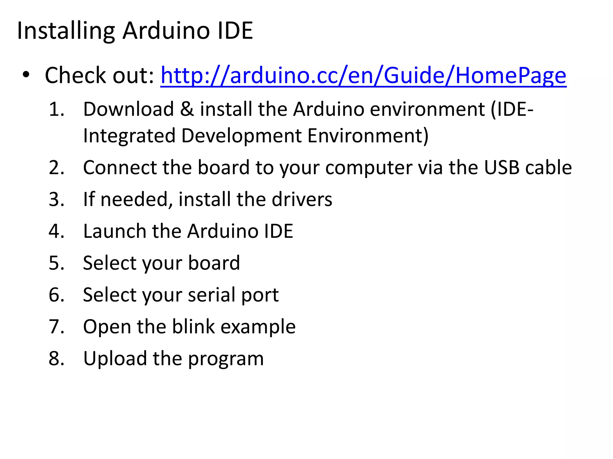
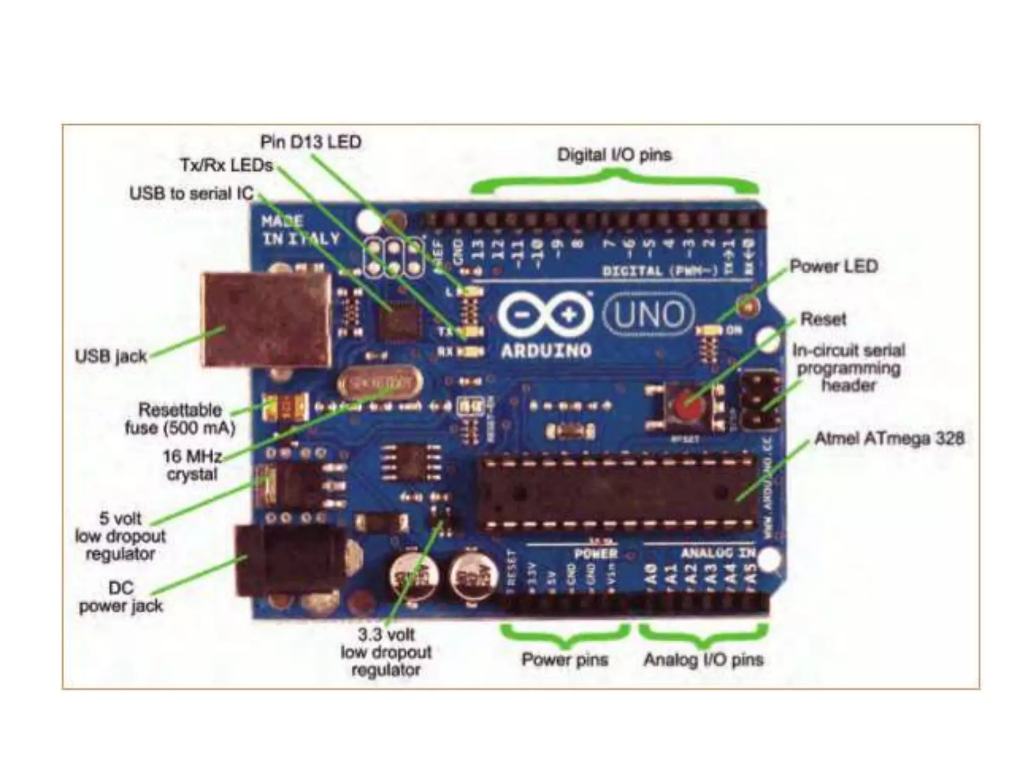
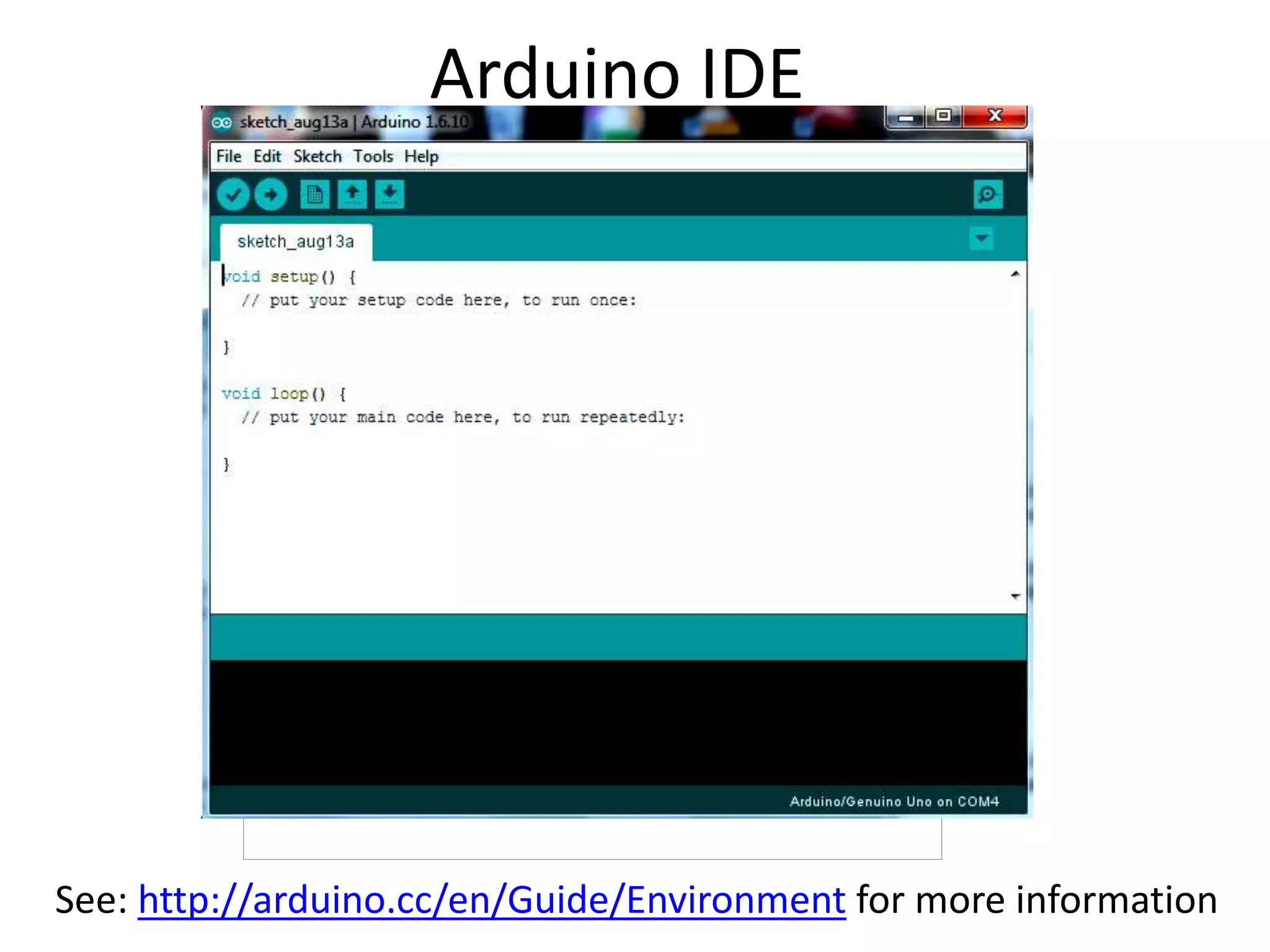
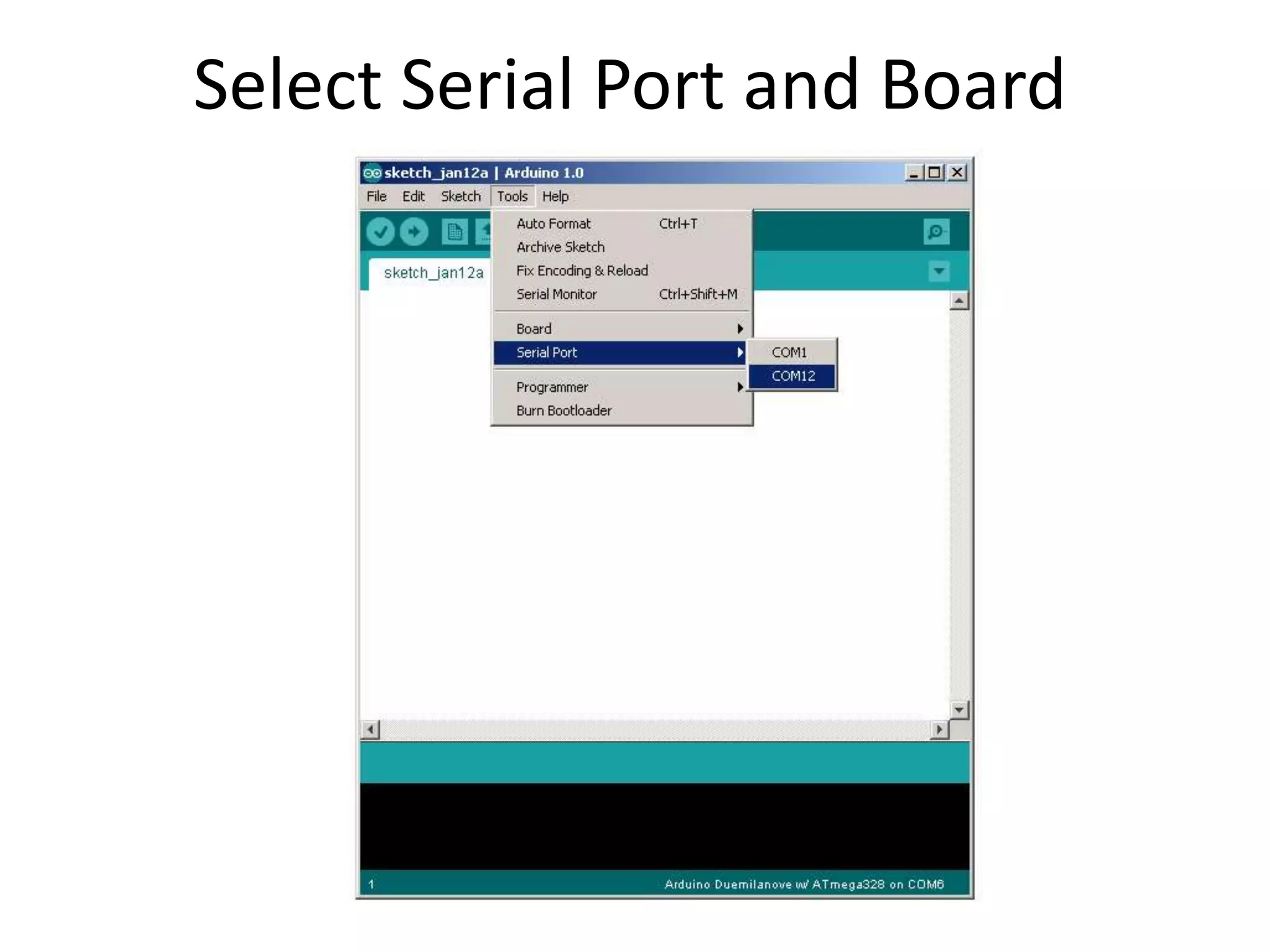
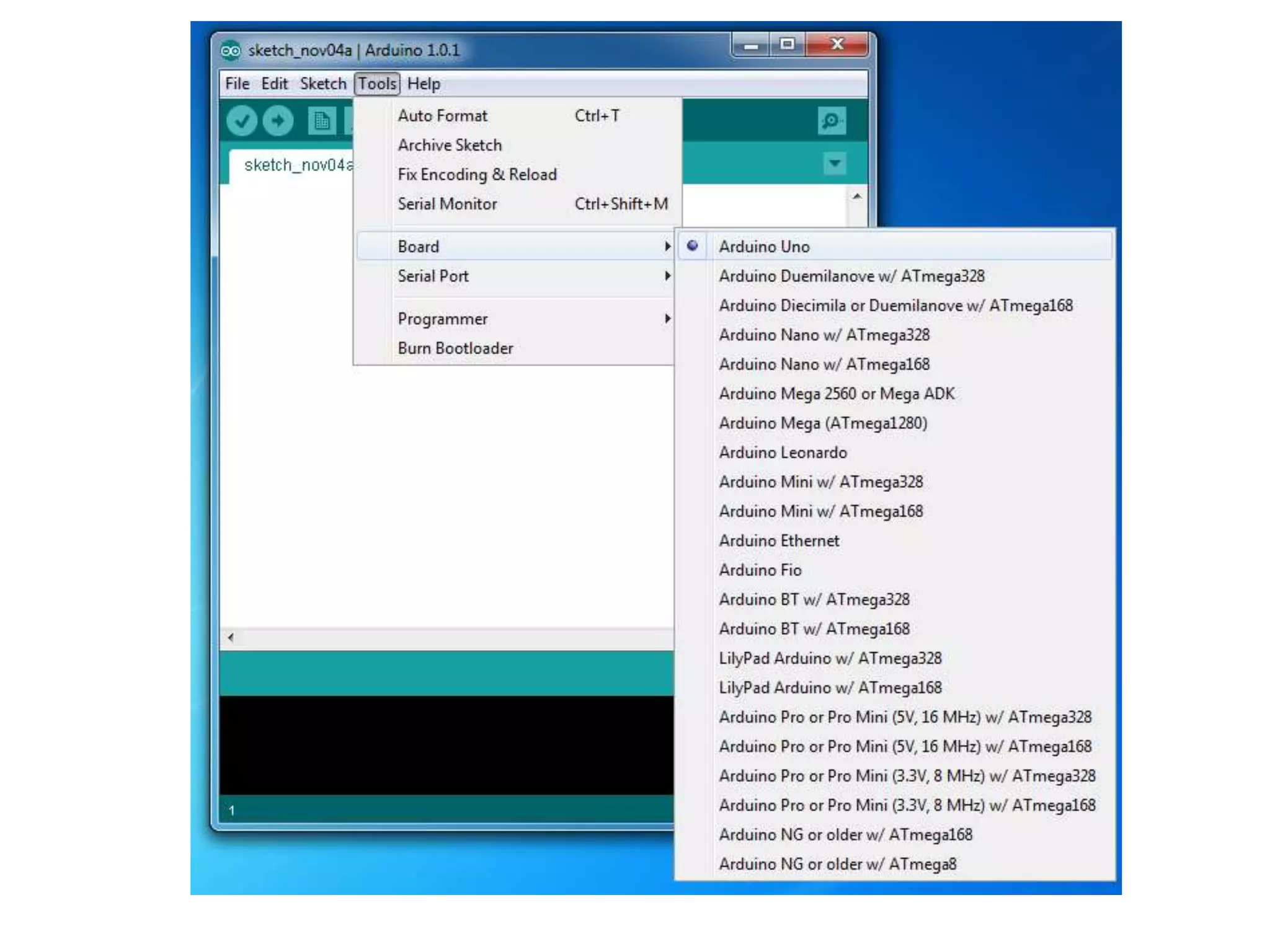
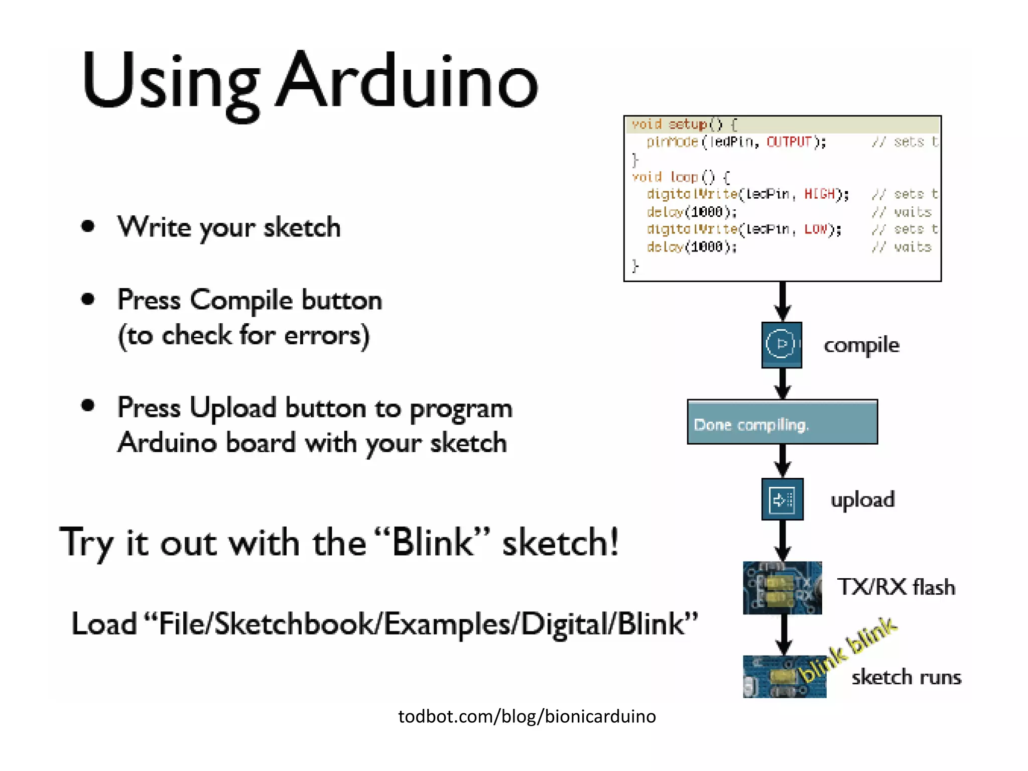
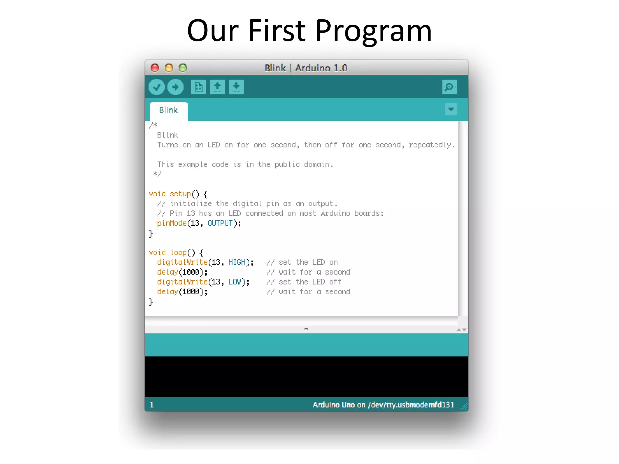
Setting up Arduino board
What is Arduino?
•A microcontroller board, contains on-board
•power supply,
•USB port to communicate with PC,
•and an Atmel microcontroller chip.
•It simplify the process of creating any control system by
providing the standard board that can be programmed and
connected to the system without the need to any sophisticated
PCB design and implementation.
•It is an open source hardware, any one can get the details of its
design and modify it or make his own one himself.
Installing Arduino IDE
• Check out: http://arduino.cc/en/Guide/HomePage
1. Download & install the Arduino environment (IDE-
Integrated Development Environment)
2. Connect the board to your computer via the USB cable
3. If needed, install the drivers
4. Launch the Arduino IDE
5. Select your board
6. Select your serial port
7. Open the blink example
8. Upload the program
Arduino Hardware : Architecture of Arduino
UNO
Arduino Hardware : Architecture of Arduino
UNO
AVR ATMega328 pin out and features
No. of Pins 28
CPU RISC 8-Bit AVR
Operating Voltage 1.8 to 5.5 V
Program Memory 32KB
Program Memory Type Flash
SRAM 2048 Bytes
EEPROM 1024 Bytes
ADC 10-Bit
Number of ADC Channels 8
PWM Pins 6
Oscillator up to 20 MHz
Timer (3) 8-Bit x 2 & 16-Bit x 1
Enhanced Power on Reset Yes
Power Up Timer Yes
I/O Pins 23
Manufacturer Microchip
SPI Yes
I2C Yes
Watchdog Timer Yes
Reset Yes
Operating Temperature -40 C to +85 C
Pin mapping between Arduino and AVR
Arduino IDE
See: http://arduino.cc/en/Guide/Environment for more information
Select Serial Port and Board
Arduino C Value Data Types
Important
• Keywords in C
– keyword is any word that has special meaning to the C
compiler.
– Because keywords are reserved for the compiler’s use,
– you cannot use them for your own variable or function
names.
• Variable Names in C
• Valid variable names may contain:
1. Characters a through z and A through Z
2. The underscore character (_)
3. Digit characters 0 through 9, provided they are not
used as the first character in the name.
boolean Data Type Example
• boolean switchState = false;
• switchState = ReadSwitchState(whichSwitch);
• if (switchState)
• {
• TurnSwitchOff(whichSwitch);
• }
• else
• {
• TurnSwitchOn(whichSwitch);
• }
Arduino Digital I/0
pinMode(pin, mode)
Sets pin to either INPUT or OUTPUT
digitalRead(pin)
Reads HIGH or LOW from a pin
digitalWrite(pin, value)
Writes HIGH or LOW to a pin
www.mikroe.com/chapters/view/1
todbot.com/blog/bionicarduino
Our First Program
Blinking of LED using LDR
To control brightness of LED
• /* LedBrightness sketch to controls the brightness of LEDs on analog output ports */
• const int firstLed = 3; // specify the pin for each of the LEDs
• const int secondLed = 5;
• const int thirdLed = 6;
• int brightness = 0;
• int increment = 1;
• void setup()
• {
• // pins driven by analogWrite do not need to be declared as outputs
• }
• void loop()
• {
• if(brightness > 255)
• {
• increment = -1; // count down after reaching 255
• }
• else if(brightness < 1)
• {
• increment = 1; // count up after dropping back down to 0
• }
• brightness = brightness + increment; // increment
(or decrement sign is minus)
• // write the brightness value to the LEDs
• analogWrite(firstLed, brightness);
• analogWrite(secondLed, brightness);
• analogWrite(thirdLed, brightness );
• delay(10); // 10ms for each step change means
2.55 secs to fade up or down
• }
Demo of Blinking LED’s at
different rates
What is PWM?
• Pulse Width Modulation (PWM) is a technique for creating a
digital square wave signal.
• A square wave has 3 main characteristics
– Amplitude - The amount the signal changes between On and
Off states
– Frequency - The number of times the signal repeats in a given time
frame
– Duty Cycle - The proportion of On time to Off time usually expressed
as a percentage
Duty cycles
PMW Pins
• Command:
analogWrite(pin,value)
• value is duty cycle:
between 0 and 255
• Examples:
analogWrite(9, 128)
for a 50% duty cycle
analogWrite(11, 64)
for a 25% duty cycle
Image from Theory and Practice of Tangible User Interfaces at UC Berkley

Arduino.pptx

  • 1.
    Setting up Arduinoboard What is Arduino? •A microcontroller board, contains on-board •power supply, •USB port to communicate with PC, •and an Atmel microcontroller chip. •It simplify the process of creating any control system by providing the standard board that can be programmed and connected to the system without the need to any sophisticated PCB design and implementation. •It is an open source hardware, any one can get the details of its design and modify it or make his own one himself.
  • 2.
    Installing Arduino IDE •Check out: http://arduino.cc/en/Guide/HomePage 1. Download & install the Arduino environment (IDE- Integrated Development Environment) 2. Connect the board to your computer via the USB cable 3. If needed, install the drivers 4. Launch the Arduino IDE 5. Select your board 6. Select your serial port 7. Open the blink example 8. Upload the program
  • 3.
    Arduino Hardware :Architecture of Arduino UNO
  • 4.
    Arduino Hardware :Architecture of Arduino UNO
  • 6.
    AVR ATMega328 pinout and features
  • 8.
    AVR ATMega328 pinout and features No. of Pins 28 CPU RISC 8-Bit AVR Operating Voltage 1.8 to 5.5 V Program Memory 32KB Program Memory Type Flash SRAM 2048 Bytes EEPROM 1024 Bytes ADC 10-Bit Number of ADC Channels 8 PWM Pins 6 Oscillator up to 20 MHz Timer (3) 8-Bit x 2 & 16-Bit x 1 Enhanced Power on Reset Yes Power Up Timer Yes I/O Pins 23 Manufacturer Microchip SPI Yes I2C Yes Watchdog Timer Yes Reset Yes Operating Temperature -40 C to +85 C
  • 9.
    Pin mapping betweenArduino and AVR
  • 10.
  • 11.
  • 13.
    Arduino C ValueData Types
  • 14.
    Important • Keywords inC – keyword is any word that has special meaning to the C compiler. – Because keywords are reserved for the compiler’s use, – you cannot use them for your own variable or function names. • Variable Names in C • Valid variable names may contain: 1. Characters a through z and A through Z 2. The underscore character (_) 3. Digit characters 0 through 9, provided they are not used as the first character in the name.
  • 15.
    boolean Data TypeExample • boolean switchState = false; • switchState = ReadSwitchState(whichSwitch); • if (switchState) • { • TurnSwitchOff(whichSwitch); • } • else • { • TurnSwitchOn(whichSwitch); • }
  • 16.
    Arduino Digital I/0 pinMode(pin,mode) Sets pin to either INPUT or OUTPUT digitalRead(pin) Reads HIGH or LOW from a pin digitalWrite(pin, value) Writes HIGH or LOW to a pin www.mikroe.com/chapters/view/1
  • 17.
  • 18.
  • 19.
    Blinking of LEDusing LDR
  • 21.
    To control brightnessof LED • /* LedBrightness sketch to controls the brightness of LEDs on analog output ports */ • const int firstLed = 3; // specify the pin for each of the LEDs • const int secondLed = 5; • const int thirdLed = 6; • int brightness = 0; • int increment = 1; • void setup() • { • // pins driven by analogWrite do not need to be declared as outputs • } • void loop() • { • if(brightness > 255) • { • increment = -1; // count down after reaching 255 • } • else if(brightness < 1) • { • increment = 1; // count up after dropping back down to 0
  • 22.
    • } • brightness= brightness + increment; // increment (or decrement sign is minus) • // write the brightness value to the LEDs • analogWrite(firstLed, brightness); • analogWrite(secondLed, brightness); • analogWrite(thirdLed, brightness ); • delay(10); // 10ms for each step change means 2.55 secs to fade up or down • }
  • 23.
    Demo of BlinkingLED’s at different rates
  • 24.
    What is PWM? •Pulse Width Modulation (PWM) is a technique for creating a digital square wave signal. • A square wave has 3 main characteristics – Amplitude - The amount the signal changes between On and Off states – Frequency - The number of times the signal repeats in a given time frame – Duty Cycle - The proportion of On time to Off time usually expressed as a percentage
  • 25.
  • 26.
    PMW Pins • Command: analogWrite(pin,value) •value is duty cycle: between 0 and 255 • Examples: analogWrite(9, 128) for a 50% duty cycle analogWrite(11, 64) for a 25% duty cycle Image from Theory and Practice of Tangible User Interfaces at UC Berkley