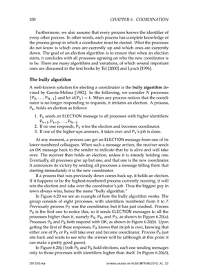
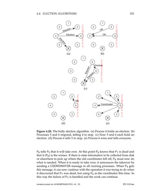
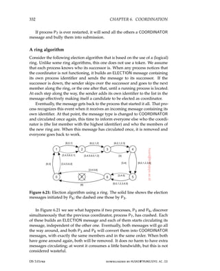
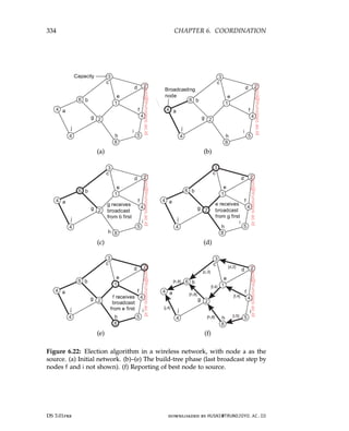
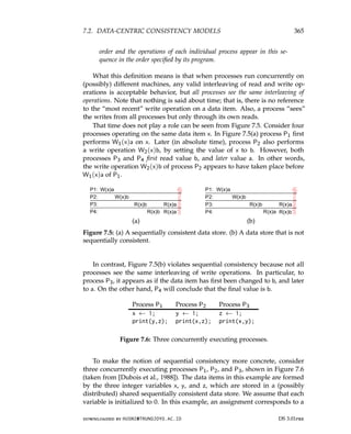
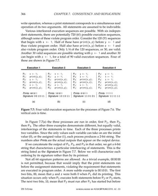
Distributed Systems
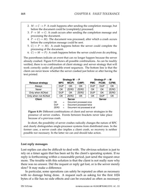
Third edition
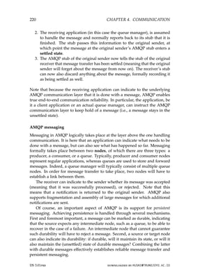
Preliminaryversion 3.01pre (2017)
Maarten van Steen
Andrew S. Tanenbaum
Distributed Systems
Third edition
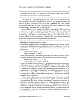
Preliminary version 3.01pre (2017)
Maarten van Steen
Andrew S. Tanenbaum
To Mariëlle, Max,and Elke
– MvS
To Suzanne, Barbara, Marvin, Aron, Nathan, Olivia, and Mirte
– AST
To Mariëlle, Max, and Elke
– MvS
To Suzanne, Barbara, Marvin, Aron, Nathan, Olivia, and Mirte
– AST
Preface
This is thethird edition of “Distributed Systems.” In many ways, it is a
huge difference compared to the previous editions, the most important one
perhaps being that we have fully integrated the “principles” and “paradigms”
by including the latter at appropriate places in the chapters that discussed the
principles of distributed systems.
The material has been thoroughly revised and extended, while at the same
time we were keen on limiting the total number of pages. The size of book
has been reduced by more than 10% compared to the second edition, which is
mainly due to removing material on paradigms. To make it easier to study
the material by a wide range of readers, we have moved specific material to
separate boxed sections. These sections can be skipped on first reading.
Another major difference is the use of coded examples, all written in
Python and supported by a simple communication system wrapped around
the Redis package. The examples in the book leave out many details for read-
ability, but the complete examples are available through the book’s Website,
hosted at www.distributed-systems.net. Next to code for running, testing,
and extending algorithms, the site provides access to slides, all figures, and
exercises.
The new material has been classroom tested, for which we particularly
thank Thilo Kielmann at VU University Amsterdam. His constructive and
critical observatiions have helped us improve matters considerably.
Our publisher Pearson Education was kind enough to return the copy-
rights, and we owe many thanks to Tracy Johnson for making this a smooth
transition. Having the copyrights back has made it possible for us to start
with something that we both feel comfortable with: running experiments. In
this case, we were looking for a means that would make the material easy
to access, relatively inexpensive to obtain, and manageable when it came to
upgrades. The book can now be (freely) downloaded, making it much easier
to use hyperlinks where appropriate. At the same time, we are offering a
printed version through Amazon.com, available at minimal costs.
The book now being fully digital allows us to incorporate updates when
xi
Preface
This is the third edition of “Distributed Systems.” In many ways, it is a
huge difference compared to the previous editions, the most important one
perhaps being that we have fully integrated the “principles” and “paradigms”
by including the latter at appropriate places in the chapters that discussed the
principles of distributed systems.
The material has been thoroughly revised and extended, while at the same
time we were keen on limiting the total number of pages. The size of book
has been reduced by more than 10% compared to the second edition, which is
mainly due to removing material on paradigms. To make it easier to study
the material by a wide range of readers, we have moved specific material to
separate boxed sections. These sections can be skipped on first reading.
Another major difference is the use of coded examples, all written in
Python and supported by a simple communication system wrapped around
the Redis package. The examples in the book leave out many details for read-
ability, but the complete examples are available through the book’s Website,
hosted at www.distributed-systems.net. Next to code for running, testing,
and extending algorithms, the site provides access to slides, all figures, and
exercises.
The new material has been classroom tested, for which we particularly
thank Thilo Kielmann at VU University Amsterdam. His constructive and
critical observatiions have helped us improve matters considerably.
Our publisher Pearson Education was kind enough to return the copy-
rights, and we owe many thanks to Tracy Johnson for making this a smooth
transition. Having the copyrights back has made it possible for us to start
with something that we both feel comfortable with: running experiments. In
this case, we were looking for a means that would make the material easy
to access, relatively inexpensive to obtain, and manageable when it came to
upgrades. The book can now be (freely) downloaded, making it much easier
to use hyperlinks where appropriate. At the same time, we are offering a
printed version through Amazon.com, available at minimal costs.
The book now being fully digital allows us to incorporate updates when
xi
14.
xii PREFACE
needed. Weplan to run updates on a yearly basis, while keeping previous
versions digitally available, as well as the printed versions for some fixed
period. Running frequent updates is not always the right thing to do from the
perspective of teaching, but yearly updates and maintaining previous versions
seems a good compromise.
Maarten van Steen
Andrew S. Tanenbaum
DS 3.01pre downloaded by HUSNI@TRUNOJOYO.AC.ID
xii PREFACE
needed. We plan to run updates on a yearly basis, while keeping previous
versions digitally available, as well as the printed versions for some fixed
period. Running frequent updates is not always the right thing to do from the
perspective of teaching, but yearly updates and maintaining previous versions
seems a good compromise.
Maarten van Steen
Andrew S. Tanenbaum
DS 3.01pre downloaded by HUSNI@TRUNOJOYO.AC.ID
15.
Chapter 1
Introduction
The paceat which computer systems change was, is, and continues to be
overwhelming. From 1945, when the modern computer era began, until about
1985, computers were large and expensive. Moreover, for lack of a way to
connect them, these computers operated independently from one another.
Starting in the mid-1980s, however, two advances in technology began to
change that situation. The first was the development of powerful microproces-
sors. Initially, these were 8-bit machines, but soon 16-, 32-, and 64-bit CPUs
became common. With multicore CPUs, we now are refacing the challenge
of adapting and developing programs to exploit parallelism. In any case, the
current generation of machines have the computing power of the mainframes
deployed 30 or 40 years ago, but for 1/1000th of the price or less.
The second development was the invention of high-speed computer net-
works. Local-area networks or LANs allow thousands of machines within a
building to be connected in such a way that small amounts of information
can be transferred in a few microseconds or so. Larger amounts of data
can be moved between machines at rates of billions of bits per second (bps).
Wide-area networks or WANs allow hundreds of millions of machines all
over the earth to be connected at speeds varying from tens of thousands to
hundreds of millions bps.
Parallel to the development of increasingly powerful and networked ma-
chines, we have also been able to witness miniaturization of computer systems
with perhaps the smartphone as the most impressive outcome. Packed with
sensors, lots of memory, and a powerful CPU, these devices are nothing less
than full-fledged computers. Of course, they also have networking capabilities.
Along the same lines, so-called plug computers are finding their way to the
A version of this chapter has been published as “A Brief Introduction to Distributed Systems,”
Computing, vol. 98(10):967-1009, 2016.
1
Chapter 1
Introduction
The pace at which computer systems change was, is, and continues to be
overwhelming. From 1945, when the modern computer era began, until about
1985, computers were large and expensive. Moreover, for lack of a way to
connect them, these computers operated independently from one another.
Starting in the mid-1980s, however, two advances in technology began to
change that situation. The first was the development of powerful microproces-
sors. Initially, these were 8-bit machines, but soon 16-, 32-, and 64-bit CPUs
became common. With multicore CPUs, we now are refacing the challenge
of adapting and developing programs to exploit parallelism. In any case, the
current generation of machines have the computing power of the mainframes
deployed 30 or 40 years ago, but for 1/1000th of the price or less.
The second development was the invention of high-speed computer net-
works. Local-area networks or LANs allow thousands of machines within a
building to be connected in such a way that small amounts of information
can be transferred in a few microseconds or so. Larger amounts of data
can be moved between machines at rates of billions of bits per second (bps).
Wide-area networks or WANs allow hundreds of millions of machines all
over the earth to be connected at speeds varying from tens of thousands to
hundreds of millions bps.
Parallel to the development of increasingly powerful and networked ma-
chines, we have also been able to witness miniaturization of computer systems
with perhaps the smartphone as the most impressive outcome. Packed with
sensors, lots of memory, and a powerful CPU, these devices are nothing less
than full-fledged computers. Of course, they also have networking capabilities.
Along the same lines, so-called plug computers are finding their way to the
A version of this chapter has been published as “A Brief Introduction to Distributed Systems,”
Computing, vol. 98(10):967-1009, 2016.
1
16.
2 CHAPTER 1.INTRODUCTION
market. These small computers, often the size of a power adapter, can be
plugged directly into an outlet and offer near-desktop performance.
The result of these technologies is that it is now not only feasible, but
easy, to put together a computing system composed of a large numbers of
networked computers, be they large or small. These computers are generally
geographically dispersed, for which reason they are usually said to form a
distributed system. The size of a distributed system may vary from a handful
of devices, to millions of computers. The interconnection network may be
wired, wireless, or a combination of both. Moreover, distributed systems are
often highly dynamic, in the sense that computers can join and leave, with the
topology and performance of the underlying network almost continuously
changing.
In this chapter, we provide an initial exploration of distributed systems
and their design goals, and follow that up by discussing some well-known
types of systems.
1.1 What is a distributed system?
Various definitions of distributed systems have been given in the literature,
none of them satisfactory, and none of them in agreement with any of the
others. For our purposes it is sufficient to give a loose characterization:
A distributed system is a collection of autonomous computing elements
that appears to its users as a single coherent system.
This definition refers to two characteristic features of distributed systems.
The first one is that a distributed system is a collection of computing elements
each being able to behave independently of each other. A computing element,
which we will generally refer to as a node, can be either a hardware device
or a software process. A second feature is that users (be they people or
applications) believe they are dealing with a single system. This means
that one way or another the autonomous nodes need to collaborate. How
to establish this collaboration lies at the heart of developing distributed
systems. Note that we are not making any assumptions concerning the
type of nodes. In principle, even within a single system, they could range
from high-performance mainframe computers to small devices in sensor
networks. Likewise, we make no assumptions concerning the way that nodes
are interconnected.
Characteristic 1: Collection of autonomous computing elements
Modern distributed systems can, and often will, consist of all kinds of nodes,
ranging from very big high-performance computers to small plug computers
or even smaller devices. A fundamental principle is that nodes can act inde-
pendently from each other, although it should be obvious that if they ignore
DS 3.01pre downloaded by HUSNI@TRUNOJOYO.AC.ID
2 CHAPTER 1. INTRODUCTION
market. These small computers, often the size of a power adapter, can be
plugged directly into an outlet and offer near-desktop performance.
The result of these technologies is that it is now not only feasible, but
easy, to put together a computing system composed of a large numbers of
networked computers, be they large or small. These computers are generally
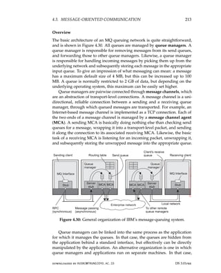
geographically dispersed, for which reason they are usually said to form a
distributed system. The size of a distributed system may vary from a handful
of devices, to millions of computers. The interconnection network may be
wired, wireless, or a combination of both. Moreover, distributed systems are
often highly dynamic, in the sense that computers can join and leave, with the
topology and performance of the underlying network almost continuously
changing.
In this chapter, we provide an initial exploration of distributed systems
and their design goals, and follow that up by discussing some well-known
types of systems.
1.1 What is a distributed system?
Various definitions of distributed systems have been given in the literature,
none of them satisfactory, and none of them in agreement with any of the
others. For our purposes it is sufficient to give a loose characterization:
A distributed system is a collection of autonomous computing elements
that appears to its users as a single coherent system.
This definition refers to two characteristic features of distributed systems.
The first one is that a distributed system is a collection of computing elements
each being able to behave independently of each other. A computing element,
which we will generally refer to as a node, can be either a hardware device
or a software process. A second feature is that users (be they people or
applications) believe they are dealing with a single system. This means
that one way or another the autonomous nodes need to collaborate. How
to establish this collaboration lies at the heart of developing distributed
systems. Note that we are not making any assumptions concerning the
type of nodes. In principle, even within a single system, they could range
from high-performance mainframe computers to small devices in sensor
networks. Likewise, we make no assumptions concerning the way that nodes
are interconnected.
Characteristic 1: Collection of autonomous computing elements
Modern distributed systems can, and often will, consist of all kinds of nodes,
ranging from very big high-performance computers to small plug computers
or even smaller devices. A fundamental principle is that nodes can act inde-
pendently from each other, although it should be obvious that if they ignore
DS 3.01pre downloaded by HUSNI@TRUNOJOYO.AC.ID
17.
1.1. WHAT ISA DISTRIBUTED SYSTEM? 3
each other, then there is no use in putting them into the same distributed
system. In practice, nodes are programmed to achieve common goals, which
are realized by exchanging messages with each other. A node reacts to in-
coming messages, which are then processed and, in turn, leading to further
communication through message passing.
An important observation is that, as a consequence of dealing with inde-
pendent nodes, each one will have its own notion of time. In other words, we
cannot always assume that there is something like a global clock. This lack
of a common reference of time leads to fundamental questions regarding the
synchronization and coordination within a distributed system, which we will
come to discuss extensively in Chapter 6. The fact that we are dealing with a
collection of nodes implies that we may also need to manage the membership
and organization of that collection. In other words, we may need to register
which nodes may or may not belong to the system, and also provide each
member with a list of nodes it can directly communicate with.
Managing group membership can be exceedingly difficult, if only for
reasons of admission control. To explain, we make a distinction between
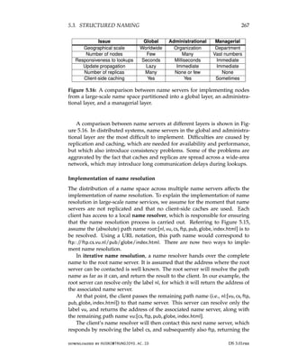
open and closed groups. In an open group, any node is allowed to join the
distributed system, effectively meaning that it can send messages to any other
node in the system. In contrast, with a closed group, only the members of
that group can communicate with each other and a separate mechanism is
needed to let a node join or leave the group.
It is not difficult to see that admission control can be difficult. First, a
mechanism is needed to authenticate a node, and as we shall see in Chap-
ter 9, if not properly designed, managing authentication can easily create
a scalability bottleneck. Second, each node must, in principle, check if it is
indeed communicating with another group member and not, for example,
with an intruder aiming to create havoc. Finally, considering that a member
can easily communicate with nonmembers, if confidentiality is an issue in the
communication within the distributed system, we may be facing trust issues.
Concerning the organization of the collection, practice shows that a dis-
tributed system is often organized as an overlay network [Tarkoma, 2010]. In
this case, a node is typically a software process equipped with a list of other
processes it can directly send messages to. It may also be the case that a neigh-
bor needs to be first looked up. Message passing is then done through TCP/IP
or UDP channels, but as we shall see in Chapter 4, higher-level facilities may
be available as well. There are roughly two types of overlay networks:
Structured overlay: In this case, each node has a well-defined set of neighbors
with whom it can communicate. For example, the nodes are organized
in a tree or logical ring.
Unstructured overlay: In these overlays, each node has a number of refer-
ences to randomly selected other nodes.
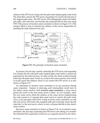
downloaded by HUSNI@TRUNOJOYO.AC.ID DS 3.01pre
1.1. WHAT IS A DISTRIBUTED SYSTEM? 3
each other, then there is no use in putting them into the same distributed
system. In practice, nodes are programmed to achieve common goals, which
are realized by exchanging messages with each other. A node reacts to in-
coming messages, which are then processed and, in turn, leading to further
communication through message passing.
An important observation is that, as a consequence of dealing with inde-
pendent nodes, each one will have its own notion of time. In other words, we
cannot always assume that there is something like a global clock. This lack
of a common reference of time leads to fundamental questions regarding the
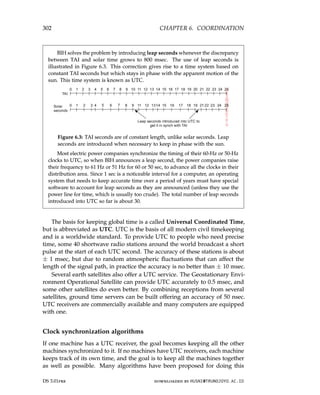
synchronization and coordination within a distributed system, which we will
come to discuss extensively in Chapter 6. The fact that we are dealing with a
collection of nodes implies that we may also need to manage the membership
and organization of that collection. In other words, we may need to register
which nodes may or may not belong to the system, and also provide each
member with a list of nodes it can directly communicate with.
Managing group membership can be exceedingly difficult, if only for
reasons of admission control. To explain, we make a distinction between
open and closed groups. In an open group, any node is allowed to join the
distributed system, effectively meaning that it can send messages to any other
node in the system. In contrast, with a closed group, only the members of
that group can communicate with each other and a separate mechanism is
needed to let a node join or leave the group.
It is not difficult to see that admission control can be difficult. First, a
mechanism is needed to authenticate a node, and as we shall see in Chap-
ter 9, if not properly designed, managing authentication can easily create
a scalability bottleneck. Second, each node must, in principle, check if it is
indeed communicating with another group member and not, for example,
with an intruder aiming to create havoc. Finally, considering that a member
can easily communicate with nonmembers, if confidentiality is an issue in the
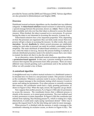
communication within the distributed system, we may be facing trust issues.
Concerning the organization of the collection, practice shows that a dis-
tributed system is often organized as an overlay network [Tarkoma, 2010]. In
this case, a node is typically a software process equipped with a list of other
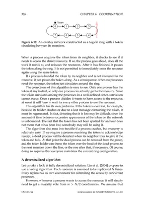
processes it can directly send messages to. It may also be the case that a neigh-
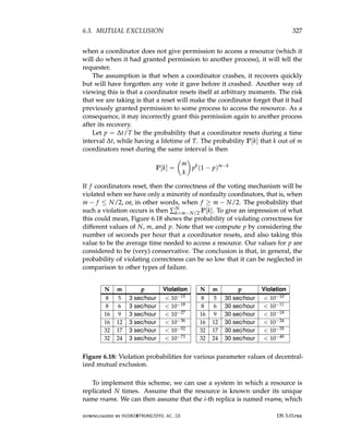
bor needs to be first looked up. Message passing is then done through TCP/IP
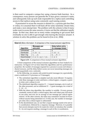
or UDP channels, but as we shall see in Chapter 4, higher-level facilities may
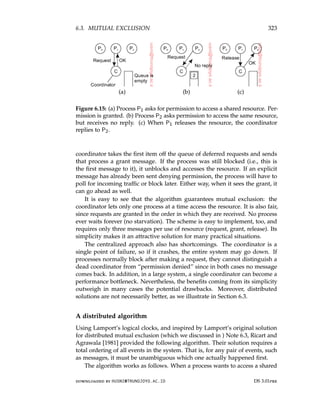
be available as well. There are roughly two types of overlay networks:
Structured overlay: In this case, each node has a well-defined set of neighbors
with whom it can communicate. For example, the nodes are organized
in a tree or logical ring.
Unstructured overlay: In these overlays, each node has a number of refer-
ences to randomly selected other nodes.
downloaded by HUSNI@TRUNOJOYO.AC.ID DS 3.01pre
18.
4 CHAPTER 1.INTRODUCTION
In any case, an overlay network should, in principle, always be connected,
meaning that between any two nodes there is always a communication path
allowing those nodes to route messages from one to the other. A well-known
class of overlays is formed by peer-to-peer (P2P) networks. Examples of
overlays will be discussed in detail in Chapter 2 and later chapters. It is
important to realize that the organization of nodes requires special effort and
that it is sometimes one of the more intricate parts of distributed-systems
management.
Characteristic 2: Single coherent system
As mentioned, a distributed system should appear as a single coherent system.
In some cases, researchers have even gone so far as to say that there should be
a single-system view, meaning that end users should not even notice that they
are dealing with the fact that processes, data, and control are dispersed across
a computer network. Achieving a single-system view is often asking too much,
for which reason, in our definition of a distributed system, we have opted for
something weaker, namely that it appears to be coherent. Roughly speaking, a
distributed system is coherent if it behaves according to the expectations of its
users. More specifically, in a single coherent system the collection of nodes
as a whole operates the same, no matter where, when, and how interaction
between a user and the system takes place.
Offering a single coherent view is often challenging enough. For example,
it requires that an end user would not be able to tell exactly on which computer
a process is currently executing, or even perhaps that part of a task has
been spawned off to another process executing somewhere else. Likewise,
where data is stored should be of no concern, and neither should it matter
that the system may be replicating data to enhance performance. This so-
called distribution transparency, which we will discuss more extensively in
Section 1.2, is an important design goal of distributed systems. In a sense, it
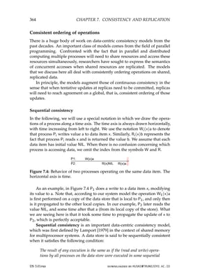
is akin to the approach taken in many Unix-like operating systems in which
resources are accessed through a unifying file-system interface, effectively
hiding the differences between files, storage devices, and main memory, but
also networks.
However, striving for a single coherent system introduces an important
trade-off. As we cannot ignore the fact that a distributed system consists of
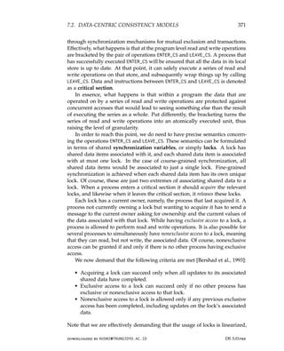
multiple, networked nodes, it is inevitable that at any time only a part of the
system fails. This means that unexpected behavior in which, for example,
some applications may continue to execute successfully while others come
to a grinding halt, is a reality that needs to be dealt with. Although partial
failures are inherent to any complex system, in distributed systems they are
particularly difficult to hide. It lead Turing-Award winner Leslie Lamport, to
describe a distributed system as “[. . .] one in which the failure of a computer
you didn’t even know existed can render your own computer unusable.”
DS 3.01pre downloaded by HUSNI@TRUNOJOYO.AC.ID
4 CHAPTER 1. INTRODUCTION
In any case, an overlay network should, in principle, always be connected,
meaning that between any two nodes there is always a communication path
allowing those nodes to route messages from one to the other. A well-known
class of overlays is formed by peer-to-peer (P2P) networks. Examples of
overlays will be discussed in detail in Chapter 2 and later chapters. It is
important to realize that the organization of nodes requires special effort and
that it is sometimes one of the more intricate parts of distributed-systems
management.
Characteristic 2: Single coherent system
As mentioned, a distributed system should appear as a single coherent system.
In some cases, researchers have even gone so far as to say that there should be
a single-system view, meaning that end users should not even notice that they
are dealing with the fact that processes, data, and control are dispersed across
a computer network. Achieving a single-system view is often asking too much,
for which reason, in our definition of a distributed system, we have opted for
something weaker, namely that it appears to be coherent. Roughly speaking, a
distributed system is coherent if it behaves according to the expectations of its
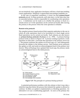
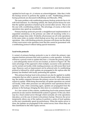
users. More specifically, in a single coherent system the collection of nodes
as a whole operates the same, no matter where, when, and how interaction
between a user and the system takes place.
Offering a single coherent view is often challenging enough. For example,
it requires that an end user would not be able to tell exactly on which computer
a process is currently executing, or even perhaps that part of a task has
been spawned off to another process executing somewhere else. Likewise,
where data is stored should be of no concern, and neither should it matter
that the system may be replicating data to enhance performance. This so-
called distribution transparency, which we will discuss more extensively in
Section 1.2, is an important design goal of distributed systems. In a sense, it
is akin to the approach taken in many Unix-like operating systems in which
resources are accessed through a unifying file-system interface, effectively
hiding the differences between files, storage devices, and main memory, but
also networks.
However, striving for a single coherent system introduces an important
trade-off. As we cannot ignore the fact that a distributed system consists of
multiple, networked nodes, it is inevitable that at any time only a part of the
system fails. This means that unexpected behavior in which, for example,
some applications may continue to execute successfully while others come
to a grinding halt, is a reality that needs to be dealt with. Although partial
failures are inherent to any complex system, in distributed systems they are
particularly difficult to hide. It lead Turing-Award winner Leslie Lamport, to
describe a distributed system as “[. . .] one in which the failure of a computer
you didn’t even know existed can render your own computer unusable.”
DS 3.01pre downloaded by HUSNI@TRUNOJOYO.AC.ID
19.
1.1. WHAT ISA DISTRIBUTED SYSTEM? 5
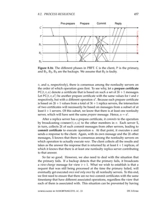
Middleware and distributed systems
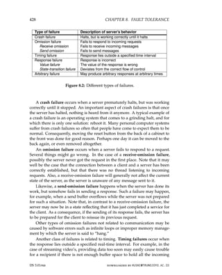
To assist the development of distributed applications, distributed systems are
often organized to have a separate layer of software that is logically placed on
top of the respective operating systems of the computers that are part of the
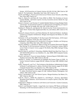
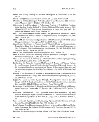
system. This organization is shown in Figure 1.1, leading to what is known as
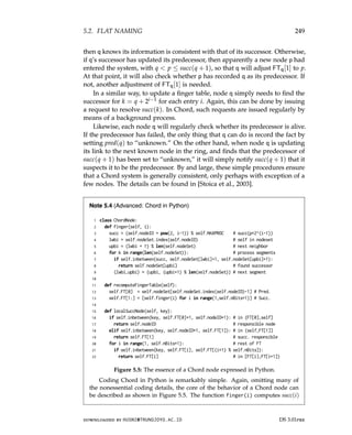
middleware [Bernstein, 1996].
Figure 1.1: A distributed system organized in a middleware layer, which
extends over multiple machines, offering each application the same interface.
Figure 1.1 shows four networked computers and three applications, of
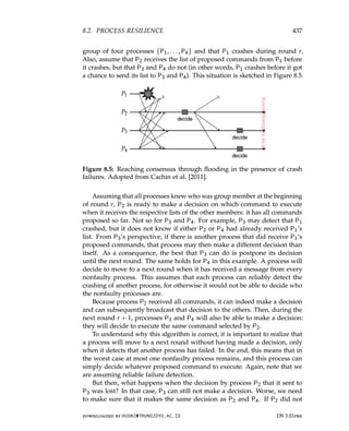
which application B is distributed across computers 2 and 3. Each application
is offered the same interface. The distributed system provides the means for
components of a single distributed application to communicate with each
other, but also to let different applications communicate. At the same time,
it hides, as best and reasonably as possible, the differences in hardware and
operating systems from each application.
In a sense, middleware is the same to a distributed system as what an
operating system is to a computer: a manager of resources offering its ap-
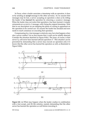
plications to efficiently share and deploy those resources across a network.
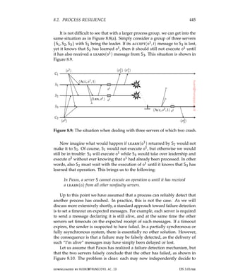
Next to resource management, it offers services that can also be found in most
operating systems, including:
• Facilities for interapplication communication.
• Security services.
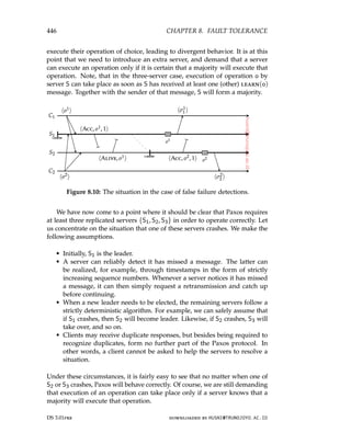
• Accounting services.
• Masking of and recovery from failures.
The main difference with their operating-system equivalents, is that mid-
dleware services are offered in a networked environment. Note also that
most services are useful to many applications. In this sense, middleware can
downloaded by HUSNI@TRUNOJOYO.AC.ID DS 3.01pre
1.1. WHAT IS A DISTRIBUTED SYSTEM? 5
Middleware and distributed systems
To assist the development of distributed applications, distributed systems are
often organized to have a separate layer of software that is logically placed on
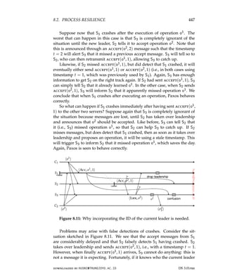
top of the respective operating systems of the computers that are part of the
system. This organization is shown in Figure 1.1, leading to what is known as
middleware [Bernstein, 1996].
Figure 1.1: A distributed system organized in a middleware layer, which
extends over multiple machines, offering each application the same interface.
Figure 1.1 shows four networked computers and three applications, of
which application B is distributed across computers 2 and 3. Each application
is offered the same interface. The distributed system provides the means for
components of a single distributed application to communicate with each
other, but also to let different applications communicate. At the same time,
it hides, as best and reasonably as possible, the differences in hardware and
operating systems from each application.
In a sense, middleware is the same to a distributed system as what an
operating system is to a computer: a manager of resources offering its ap-
plications to efficiently share and deploy those resources across a network.
Next to resource management, it offers services that can also be found in most
operating systems, including:
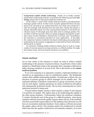
• Facilities for interapplication communication.
• Security services.
• Accounting services.
• Masking of and recovery from failures.
The main difference with their operating-system equivalents, is that mid-
dleware services are offered in a networked environment. Note also that
most services are useful to many applications. In this sense, middleware can
downloaded by HUSNI@TRUNOJOYO.AC.ID DS 3.01pre
20.
6 CHAPTER 1.INTRODUCTION
also be viewed as a container of commonly used components and functions
that now no longer have to be implemented by applications separately. To
further illustrate these points, let us briefly consider a few examples of typical
middleware services.
Communication: A common communication service is the so-called Remote
Procedure Call (RPC). An RPC service, to which we return in Chapter 4,
allows an application to invoke a function that is implemented and
executed on a remote computer as if it was locally available. To this
end, a developer need merely specify the function header expressed in
a special programming language, from which the RPC subsystem can
then generate the necessary code that establishes remote invocations.
Transactions: Many applications make use of multiple services that are dis-
tributed among several computers. Middleware generally offers special
support for executing such services in an all-or-nothing fashion, com-
monly referred to as an atomic transaction. In this case, the application
developer need only specify the remote services involved, and by fol-
lowing a standardized protocol, the middleware makes sure that every
service is invoked, or none at all.
Service composition: It is becoming increasingly common to develop new
applications by taking existing programs and gluing them together. This
is notably the case for many Web-based applications, in particular those
known as Web services [Alonso et al., 2004]. Web-based middleware can
help by standardizing the way Web services are accessed and providing
the means to generate their functions in a specific order. A simple
example of how service composition is deployed is formed by mashups:
Web pages that combine and aggregate data from different sources.
Well-known mashups are those based on Google maps in which maps
are enhanced with extra information such as trip planners or real-time
weather forecasts.
Reliability: As a last example, there has been a wealth of research on pro-
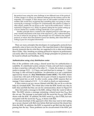
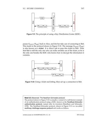
viding enhanced functions for building reliable distributed applications.
The Horus toolkit [van Renesse et al., 1994] allows a developer to build
an application as a group of processes such that any message sent by
one process is guaranteed to be received by all or no other process. As it
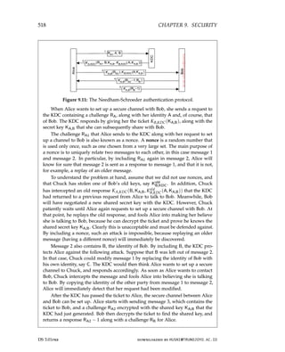
turns out, such guarantees can greatly simplify developing distributed
applications and are typically implemented as part of the middleware.
Note 1.1 (Historical note: The term middleware)
Although the term middleware became popular in the mid 1990s, it was most
likely mentioned for the first time in a report on a NATO software engineering
DS 3.01pre downloaded by HUSNI@TRUNOJOYO.AC.ID
6 CHAPTER 1. INTRODUCTION
also be viewed as a container of commonly used components and functions
that now no longer have to be implemented by applications separately. To
further illustrate these points, let us briefly consider a few examples of typical
middleware services.
Communication: A common communication service is the so-called Remote
Procedure Call (RPC). An RPC service, to which we return in Chapter 4,
allows an application to invoke a function that is implemented and
executed on a remote computer as if it was locally available. To this
end, a developer need merely specify the function header expressed in
a special programming language, from which the RPC subsystem can
then generate the necessary code that establishes remote invocations.
Transactions: Many applications make use of multiple services that are dis-
tributed among several computers. Middleware generally offers special
support for executing such services in an all-or-nothing fashion, com-
monly referred to as an atomic transaction. In this case, the application
developer need only specify the remote services involved, and by fol-
lowing a standardized protocol, the middleware makes sure that every
service is invoked, or none at all.
Service composition: It is becoming increasingly common to develop new
applications by taking existing programs and gluing them together. This
is notably the case for many Web-based applications, in particular those
known as Web services [Alonso et al., 2004]. Web-based middleware can
help by standardizing the way Web services are accessed and providing
the means to generate their functions in a specific order. A simple
example of how service composition is deployed is formed by mashups:
Web pages that combine and aggregate data from different sources.
Well-known mashups are those based on Google maps in which maps
are enhanced with extra information such as trip planners or real-time
weather forecasts.
Reliability: As a last example, there has been a wealth of research on pro-
viding enhanced functions for building reliable distributed applications.
The Horus toolkit [van Renesse et al., 1994] allows a developer to build
an application as a group of processes such that any message sent by
one process is guaranteed to be received by all or no other process. As it
turns out, such guarantees can greatly simplify developing distributed
applications and are typically implemented as part of the middleware.
Note 1.1 (Historical note: The term middleware)
Although the term middleware became popular in the mid 1990s, it was most
likely mentioned for the first time in a report on a NATO software engineering
DS 3.01pre downloaded by HUSNI@TRUNOJOYO.AC.ID
21.
1.2. DESIGN GOALS7
conference, edited by Peter Naur and Brian Randell in October 1968 [Naur and
Randell, 1968]. Indeed, middleware was placed precisely between applications
and service routines (the equivalent of operating systems).
1.2 Design goals
Just because it is possible to build distributed systems does not necessarily
mean that it is a good idea. In this section we discuss four important goals
that should be met to make building a distributed system worth the effort. A
distributed system should make resources easily accessible; it should hide the
fact that resources are distributed across a network; it should be open; and it
should be scalable.
Supporting resource sharing
An important goal of a distributed system is to make it easy for users (and
applications) to access and share remote resources. Resources can be virtually
anything, but typical examples include peripherals, storage facilities, data,
files, services, and networks, to name just a few. There are many reasons for
wanting to share resources. One obvious reason is that of economics. For
example, it is cheaper to have a single high-end reliable storage facility be
shared than having to buy and maintain storage for each user separately.
Connecting users and resources also makes it easier to collaborate and
exchange information, as is illustrated by the success of the Internet with
its simple protocols for exchanging files, mail, documents, audio, and video.
The connectivity of the Internet has allowed geographically widely dispersed
groups of people to work together by means of all kinds of groupware, that is,
software for collaborative editing, teleconferencing, and so on, as is illustrated
by multinational software-development companies that have outsourced much
of their code production to Asia.
However, resource sharing in distributed systems is perhaps best illustrated
by the success of file-sharing peer-to-peer networks like BitTorrent. These
distributed systems make it extremely simple for users to share files across
the Internet. Peer-to-peer networks are often associated with distribution of
media files such as audio and video. In other cases, the technology is used for
distributing large amounts of data, as in the case of software updates, backup
services, and data synchronization across multiple servers.
Note 1.2 (More information: Sharing folders worldwide)
To illustrate where we stand when it comes to seamless integration of resource-
sharing facilities in a networked environment, Web-based services are now de-
ployed that allow a group of users to place files into a special shared folder that is
downloaded by HUSNI@TRUNOJOYO.AC.ID DS 3.01pre
1.2. DESIGN GOALS 7
conference, edited by Peter Naur and Brian Randell in October 1968 [Naur and
Randell, 1968]. Indeed, middleware was placed precisely between applications
and service routines (the equivalent of operating systems).
1.2 Design goals
Just because it is possible to build distributed systems does not necessarily
mean that it is a good idea. In this section we discuss four important goals
that should be met to make building a distributed system worth the effort. A
distributed system should make resources easily accessible; it should hide the
fact that resources are distributed across a network; it should be open; and it
should be scalable.
Supporting resource sharing
An important goal of a distributed system is to make it easy for users (and
applications) to access and share remote resources. Resources can be virtually
anything, but typical examples include peripherals, storage facilities, data,
files, services, and networks, to name just a few. There are many reasons for
wanting to share resources. One obvious reason is that of economics. For
example, it is cheaper to have a single high-end reliable storage facility be
shared than having to buy and maintain storage for each user separately.
Connecting users and resources also makes it easier to collaborate and
exchange information, as is illustrated by the success of the Internet with
its simple protocols for exchanging files, mail, documents, audio, and video.
The connectivity of the Internet has allowed geographically widely dispersed
groups of people to work together by means of all kinds of groupware, that is,
software for collaborative editing, teleconferencing, and so on, as is illustrated
by multinational software-development companies that have outsourced much
of their code production to Asia.
However, resource sharing in distributed systems is perhaps best illustrated
by the success of file-sharing peer-to-peer networks like BitTorrent. These
distributed systems make it extremely simple for users to share files across
the Internet. Peer-to-peer networks are often associated with distribution of
media files such as audio and video. In other cases, the technology is used for
distributing large amounts of data, as in the case of software updates, backup
services, and data synchronization across multiple servers.
Note 1.2 (More information: Sharing folders worldwide)
To illustrate where we stand when it comes to seamless integration of resource-
sharing facilities in a networked environment, Web-based services are now de-
ployed that allow a group of users to place files into a special shared folder that is
downloaded by HUSNI@TRUNOJOYO.AC.ID DS 3.01pre
22.
8 CHAPTER 1.INTRODUCTION
maintained by a third party somewhere on the Internet. Using special software,
the shared folder is barely distinguishable from other folders on a user’s computer.
In effect, these services replace the use of a shared directory on a local distributed
file system, making data available to users independent of the organization they
belong to, and independent of where they are. The service is offered for different
operating systems. Where exactly data are stored is completely hidden from the
end user.
Making distribution transparent
An important goal of a distributed system is to hide the fact that its processes
and resources are physically distributed across multiple computers possibly
separated by large distances. In other words, it tries to make the distribution
of processes and resources transparent, that is, invisible, to end users and
applications.
Types of distribution transparency
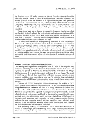
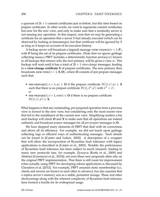
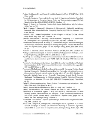
The concept of transparency can be applied to several aspects of a distributed
system, of which the most important ones are listed in Figure 1.2. We use the
term object to mean either a process or a resource.
Transparency Description
Access Hide differences in data representation and how an object is
accessed
Location Hide where an object is located
Relocation Hide that an object may be moved to another location while
in use
Migration Hide that an object may move to another location
Replication Hide that an object is replicated
Concurrency Hide that an object may be shared by several independent
users
Failure Hide the failure and recovery of an object
Figure 1.2: Different forms of transparency in a distributed system (see ISO
[1995]). An object can be a resource or a process.
Access transparency deals with hiding differences in data representation
and the way that objects can be accessed. At a basic level, we want to hide
differences in machine architectures, but more important is that we reach
agreement on how data is to be represented by different machines and operat-
ing systems. For example, a distributed system may have computer systems
DS 3.01pre downloaded by HUSNI@TRUNOJOYO.AC.ID
8 CHAPTER 1. INTRODUCTION
maintained by a third party somewhere on the Internet. Using special software,
the shared folder is barely distinguishable from other folders on a user’s computer.
In effect, these services replace the use of a shared directory on a local distributed
file system, making data available to users independent of the organization they
belong to, and independent of where they are. The service is offered for different
operating systems. Where exactly data are stored is completely hidden from the
end user.
Making distribution transparent
An important goal of a distributed system is to hide the fact that its processes
and resources are physically distributed across multiple computers possibly
separated by large distances. In other words, it tries to make the distribution
of processes and resources transparent, that is, invisible, to end users and
applications.
Types of distribution transparency
The concept of transparency can be applied to several aspects of a distributed
system, of which the most important ones are listed in Figure 1.2. We use the
term object to mean either a process or a resource.
Transparency Description
Access Hide differences in data representation and how an object is
accessed
Location Hide where an object is located
Relocation Hide that an object may be moved to another location while
in use
Migration Hide that an object may move to another location
Replication Hide that an object is replicated
Concurrency Hide that an object may be shared by several independent
users
Failure Hide the failure and recovery of an object
Figure 1.2: Different forms of transparency in a distributed system (see ISO
[1995]). An object can be a resource or a process.
Access transparency deals with hiding differences in data representation
and the way that objects can be accessed. At a basic level, we want to hide
differences in machine architectures, but more important is that we reach
agreement on how data is to be represented by different machines and operat-
ing systems. For example, a distributed system may have computer systems
DS 3.01pre downloaded by HUSNI@TRUNOJOYO.AC.ID
23.
1.2. DESIGN GOALS9
that run different operating systems, each having their own file-naming con-
ventions. Differences in naming conventions, differences in file operations, or
differences in how low-level communication with other processes is to take
place, are examples of access issues that should preferably be hidden from
users and applications.
An important group of transparency types concerns the location of a pro-
cess or resource. Location transparency refers to the fact that users cannot
tell where an object is physically located in the system. Naming plays an
important role in achieving location transparency. In particular, location
transparency can often be achieved by assigning only logical names to re-
sources, that is, names in which the location of a resource is not secretly
encoded. An example of a such a name is the uniform resource locator (URL)
http://www.prenhall.com/index.html, which gives no clue about the actual
location of Prentice Hall’s main Web server. The URL also gives no clue as
to whether the file index.html has always been at its current location or was
recently moved there. For example, the entire site may have been moved from
one data center to another, yet users should not notice. The latter is an exam-
ple of relocation transparency, which is becoming increasingly important in
the context of cloud computing to which we return later in this chapter.
Where relocation transparency refers to being moved by the distributed
system, migration transparency is offered by a distributed system when it
supports the mobility of processes and resources initiated by users, with-
out affecting ongoing communication and operations. A typical example
is communication between mobile phones: regardless whether two people
are actually moving, mobile phones will allow them to continue their con-
versation. Other examples that come to mind include online tracking and
tracing of goods as they are being transported from one place to another,
and teleconferencing (partly) using devices that are equipped with mobile
Internet.
As we shall see, replication plays an important role in distributed systems.
For example, resources may be replicated to increase availability or to im-
prove performance by placing a copy close to the place where it is accessed.
Replication transparency deals with hiding the fact that several copies of a
resource exist, or that several processes are operating in some form of lockstep
mode so that one can take over when another fails. To hide replication from
users, it is necessary that all replicas have the same name. Consequently,
a system that supports replication transparency should generally support
location transparency as well, because it would otherwise be impossible to
refer to replicas at different locations.
We already mentioned that an important goal of distributed systems is
to allow sharing of resources. In many cases, sharing resources is done in a
cooperative way, as in the case of communication channels. However, there
are also many examples of competitive sharing of resources. For example,
downloaded by HUSNI@TRUNOJOYO.AC.ID DS 3.01pre
1.2. DESIGN GOALS 9
that run different operating systems, each having their own file-naming con-
ventions. Differences in naming conventions, differences in file operations, or
differences in how low-level communication with other processes is to take
place, are examples of access issues that should preferably be hidden from
users and applications.
An important group of transparency types concerns the location of a pro-
cess or resource. Location transparency refers to the fact that users cannot
tell where an object is physically located in the system. Naming plays an
important role in achieving location transparency. In particular, location
transparency can often be achieved by assigning only logical names to re-
sources, that is, names in which the location of a resource is not secretly
encoded. An example of a such a name is the uniform resource locator (URL)
http://www.prenhall.com/index.html, which gives no clue about the actual
location of Prentice Hall’s main Web server. The URL also gives no clue as
to whether the file index.html has always been at its current location or was
recently moved there. For example, the entire site may have been moved from
one data center to another, yet users should not notice. The latter is an exam-
ple of relocation transparency, which is becoming increasingly important in
the context of cloud computing to which we return later in this chapter.
Where relocation transparency refers to being moved by the distributed
system, migration transparency is offered by a distributed system when it
supports the mobility of processes and resources initiated by users, with-
out affecting ongoing communication and operations. A typical example
is communication between mobile phones: regardless whether two people
are actually moving, mobile phones will allow them to continue their con-
versation. Other examples that come to mind include online tracking and
tracing of goods as they are being transported from one place to another,
and teleconferencing (partly) using devices that are equipped with mobile
Internet.
As we shall see, replication plays an important role in distributed systems.
For example, resources may be replicated to increase availability or to im-
prove performance by placing a copy close to the place where it is accessed.
Replication transparency deals with hiding the fact that several copies of a
resource exist, or that several processes are operating in some form of lockstep
mode so that one can take over when another fails. To hide replication from
users, it is necessary that all replicas have the same name. Consequently,
a system that supports replication transparency should generally support
location transparency as well, because it would otherwise be impossible to
refer to replicas at different locations.
We already mentioned that an important goal of distributed systems is
to allow sharing of resources. In many cases, sharing resources is done in a
cooperative way, as in the case of communication channels. However, there
are also many examples of competitive sharing of resources. For example,
downloaded by HUSNI@TRUNOJOYO.AC.ID DS 3.01pre
24.
10 CHAPTER 1.INTRODUCTION
two independent users may each have stored their files on the same file server
or may be accessing the same tables in a shared database. In such cases, it
is important that each user does not notice that the other is making use of
the same resource. This phenomenon is called concurrency transparency.
An important issue is that concurrent access to a shared resource leaves that
resource in a consistent state. Consistency can be achieved through locking
mechanisms, by which users are, in turn, given exclusive access to the desired
resource. A more refined mechanism is to make use of transactions, but these
may be difficult to implement in a distributed system, notably when scalability
is an issue.
Last, but certainly not least, it is important that a distributed system
provides failure transparency. This means that a user or application does not
notice that some piece of the system fails to work properly, and that the system
subsequently (and automatically) recovers from that failure. Masking failures
is one of the hardest issues in distributed systems and is even impossible
when certain apparently realistic assumptions are made, as we will discuss
in Chapter 8. The main difficulty in masking and transparently recovering
from failures lies in the inability to distinguish between a dead process and a
painfully slowly responding one. For example, when contacting a busy Web
server, a browser will eventually time out and report that the Web page is
unavailable. At that point, the user cannot tell whether the server is actually
down or that the network is badly congested.
Degree of distribution transparency
Although distribution transparency is generally considered preferable for any
distributed system, there are situations in which attempting to blindly hide
all distribution aspects from users is not a good idea. A simple example is
requesting your electronic newspaper to appear in your mailbox before 7 AM
local time, as usual, while you are currently at the other end of the world
living in a different time zone. Your morning paper will not be the morning
paper you are used to.
Likewise, a wide-area distributed system that connects a process in San
Francisco to a process in Amsterdam cannot be expected to hide the fact
that Mother Nature will not allow it to send a message from one process to
the other in less than approximately 35 milliseconds. Practice shows that it
actually takes several hundred milliseconds using a computer network. Signal
transmission is not only limited by the speed of light, but also by limited
processing capacities and delays in the intermediate switches.
There is also a trade-off between a high degree of transparency and the
performance of a system. For example, many Internet applications repeatedly
try to contact a server before finally giving up. Consequently, attempting to
mask a transient server failure before trying another one may slow down the
DS 3.01pre downloaded by HUSNI@TRUNOJOYO.AC.ID
10 CHAPTER 1. INTRODUCTION
two independent users may each have stored their files on the same file server
or may be accessing the same tables in a shared database. In such cases, it
is important that each user does not notice that the other is making use of
the same resource. This phenomenon is called concurrency transparency.
An important issue is that concurrent access to a shared resource leaves that
resource in a consistent state. Consistency can be achieved through locking
mechanisms, by which users are, in turn, given exclusive access to the desired
resource. A more refined mechanism is to make use of transactions, but these
may be difficult to implement in a distributed system, notably when scalability
is an issue.
Last, but certainly not least, it is important that a distributed system
provides failure transparency. This means that a user or application does not
notice that some piece of the system fails to work properly, and that the system
subsequently (and automatically) recovers from that failure. Masking failures
is one of the hardest issues in distributed systems and is even impossible
when certain apparently realistic assumptions are made, as we will discuss
in Chapter 8. The main difficulty in masking and transparently recovering
from failures lies in the inability to distinguish between a dead process and a
painfully slowly responding one. For example, when contacting a busy Web
server, a browser will eventually time out and report that the Web page is
unavailable. At that point, the user cannot tell whether the server is actually
down or that the network is badly congested.
Degree of distribution transparency
Although distribution transparency is generally considered preferable for any
distributed system, there are situations in which attempting to blindly hide
all distribution aspects from users is not a good idea. A simple example is
requesting your electronic newspaper to appear in your mailbox before 7 AM
local time, as usual, while you are currently at the other end of the world
living in a different time zone. Your morning paper will not be the morning
paper you are used to.
Likewise, a wide-area distributed system that connects a process in San
Francisco to a process in Amsterdam cannot be expected to hide the fact
that Mother Nature will not allow it to send a message from one process to
the other in less than approximately 35 milliseconds. Practice shows that it
actually takes several hundred milliseconds using a computer network. Signal
transmission is not only limited by the speed of light, but also by limited
processing capacities and delays in the intermediate switches.
There is also a trade-off between a high degree of transparency and the
performance of a system. For example, many Internet applications repeatedly
try to contact a server before finally giving up. Consequently, attempting to
mask a transient server failure before trying another one may slow down the
DS 3.01pre downloaded by HUSNI@TRUNOJOYO.AC.ID
25.
1.2. DESIGN GOALS11
system as a whole. In such a case, it may have been better to give up earlier,
or at least let the user cancel the attempts to make contact.
Another example is where we need to guarantee that several replicas,
located on different continents, must be consistent all the time. In other words,
if one copy is changed, that change should be propagated to all copies before
allowing any other operation. It is clear that a single update operation may
now even take seconds to complete, something that cannot be hidden from
users.
Finally, there are situations in which it is not at all obvious that hiding
distribution is a good idea. As distributed systems are expanding to devices
that people carry around and where the very notion of location and context
awareness is becoming increasingly important, it may be best to actually expose
distribution rather than trying to hide it. An obvious example is making use
of location-based services, which can often be found on mobile phones, such
as finding the nearest Chinese take-away or checking whether any of your
friends are nearby.
There are also other arguments against distribution transparency. Recog-
nizing that full distribution transparency is simply impossible, we should ask
ourselves whether it is even wise to pretend that we can achieve it. It may
be much better to make distribution explicit so that the user and applica-
tion developer are never tricked into believing that there is such a thing as
transparency. The result will be that users will much better understand the
(sometimes unexpected) behavior of a distributed system, and are thus much
better prepared to deal with this behavior.
Note 1.3 (Discussion: Against distribution transparency)
Several researchers have argued that hiding distribution will only lead to further
complicating the development of distributed systems, exactly for the reason that
full distribution transparency can never be achieved. A popular technique for
achieving access transparency is to extend procedure calls to remote servers. How-
ever, Waldo et al. [1997] already pointed out that attempting to hide distribution
by means of such remote procedure calls can lead to poorly understood semantics,
for the simple reason that a procedure call does change when executed over a
faulty communication link.
As an alternative, various researchers and practitioners are now arguing for
less transparency, for example, by more explicitly using message-style commu-
nication, or more explicitly posting requests to, and getting results from remote
machines, as is done in the Web when fetching pages. Such solutions will be
discussed in detail in the next chapter.
A somewhat radical standpoint is taken by Wams [2011] by stating that partial
failures preclude relying on the successful execution of a remote service. If such
reliability cannot be guaranteed, it is then best to always perform only local
executions, leading to the copy-before-use principle. According to this principle,
data can be accessed only after they have been transferred to the machine of the
downloaded by HUSNI@TRUNOJOYO.AC.ID DS 3.01pre
1.2. DESIGN GOALS 11
system as a whole. In such a case, it may have been better to give up earlier,
or at least let the user cancel the attempts to make contact.
Another example is where we need to guarantee that several replicas,
located on different continents, must be consistent all the time. In other words,
if one copy is changed, that change should be propagated to all copies before
allowing any other operation. It is clear that a single update operation may
now even take seconds to complete, something that cannot be hidden from
users.
Finally, there are situations in which it is not at all obvious that hiding
distribution is a good idea. As distributed systems are expanding to devices
that people carry around and where the very notion of location and context
awareness is becoming increasingly important, it may be best to actually expose
distribution rather than trying to hide it. An obvious example is making use
of location-based services, which can often be found on mobile phones, such
as finding the nearest Chinese take-away or checking whether any of your
friends are nearby.
There are also other arguments against distribution transparency. Recog-
nizing that full distribution transparency is simply impossible, we should ask
ourselves whether it is even wise to pretend that we can achieve it. It may
be much better to make distribution explicit so that the user and applica-
tion developer are never tricked into believing that there is such a thing as
transparency. The result will be that users will much better understand the
(sometimes unexpected) behavior of a distributed system, and are thus much
better prepared to deal with this behavior.
Note 1.3 (Discussion: Against distribution transparency)
Several researchers have argued that hiding distribution will only lead to further
complicating the development of distributed systems, exactly for the reason that
full distribution transparency can never be achieved. A popular technique for
achieving access transparency is to extend procedure calls to remote servers. How-
ever, Waldo et al. [1997] already pointed out that attempting to hide distribution
by means of such remote procedure calls can lead to poorly understood semantics,
for the simple reason that a procedure call does change when executed over a
faulty communication link.
As an alternative, various researchers and practitioners are now arguing for
less transparency, for example, by more explicitly using message-style commu-
nication, or more explicitly posting requests to, and getting results from remote
machines, as is done in the Web when fetching pages. Such solutions will be
discussed in detail in the next chapter.
A somewhat radical standpoint is taken by Wams [2011] by stating that partial
failures preclude relying on the successful execution of a remote service. If such
reliability cannot be guaranteed, it is then best to always perform only local
executions, leading to the copy-before-use principle. According to this principle,
data can be accessed only after they have been transferred to the machine of the
downloaded by HUSNI@TRUNOJOYO.AC.ID DS 3.01pre
26.
12 CHAPTER 1.INTRODUCTION
process wanting that data. Moreover, modifying a data item should not be done.
Instead, it can only be updated to a new version. It is not difficult to imagine
that many other problems will surface. However, Wams shows that many existing
applications can be retrofitted to this alternative approach without sacrificing
functionality.
The conclusion is that aiming for distribution transparency may be a
nice goal when designing and implementing distributed systems, but that
it should be considered together with other issues such as performance
and comprehensibility. The price for achieving full transparency may be
surprisingly high.
Being open
Another important goal of distributed systems is openness. An open dis-
tributed system is essentially a system that offers components that can easily
be used by, or integrated into other systems. At the same time, an open
distributed system itself will often consist of components that originate from
elsewhere.
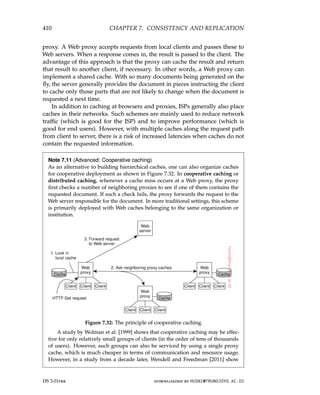
Interoperability, composability, and extensibility
To be open means that components should adhere to standard rules that
describe the syntax and semantics of what those components have to offer (i.e.,
which service they provide). A general approach is to define services through
interfaces using an Interface Definition Language (IDL). Interface definitions
written in an IDL nearly always capture only the syntax of services. In other
words, they specify precisely the names of the functions that are available
together with types of the parameters, return values, possible exceptions that
can be raised, and so on. The hard part is specifying precisely what those
services do, that is, the semantics of interfaces. In practice, such specifications
are given in an informal way by means of natural language.
If properly specified, an interface definition allows an arbitrary process
that needs a certain interface, to talk to another process that provides that
interface. It also allows two independent parties to build completely different
implementations of those interfaces, leading to two separate components that
operate in exactly the same way.
Proper specifications are complete and neutral. Complete means that
everything that is necessary to make an implementation has indeed been
specified. However, many interface definitions are not at all complete, so
that it is necessary for a developer to add implementation-specific details.
Just as important is the fact that specifications do not prescribe what an
implementation should look like; they should be neutral.
DS 3.01pre downloaded by HUSNI@TRUNOJOYO.AC.ID
12 CHAPTER 1. INTRODUCTION
process wanting that data. Moreover, modifying a data item should not be done.
Instead, it can only be updated to a new version. It is not difficult to imagine
that many other problems will surface. However, Wams shows that many existing
applications can be retrofitted to this alternative approach without sacrificing
functionality.
The conclusion is that aiming for distribution transparency may be a
nice goal when designing and implementing distributed systems, but that
it should be considered together with other issues such as performance
and comprehensibility. The price for achieving full transparency may be
surprisingly high.
Being open
Another important goal of distributed systems is openness. An open dis-
tributed system is essentially a system that offers components that can easily
be used by, or integrated into other systems. At the same time, an open
distributed system itself will often consist of components that originate from
elsewhere.
Interoperability, composability, and extensibility
To be open means that components should adhere to standard rules that
describe the syntax and semantics of what those components have to offer (i.e.,
which service they provide). A general approach is to define services through
interfaces using an Interface Definition Language (IDL). Interface definitions
written in an IDL nearly always capture only the syntax of services. In other
words, they specify precisely the names of the functions that are available
together with types of the parameters, return values, possible exceptions that
can be raised, and so on. The hard part is specifying precisely what those
services do, that is, the semantics of interfaces. In practice, such specifications
are given in an informal way by means of natural language.
If properly specified, an interface definition allows an arbitrary process
that needs a certain interface, to talk to another process that provides that
interface. It also allows two independent parties to build completely different
implementations of those interfaces, leading to two separate components that
operate in exactly the same way.
Proper specifications are complete and neutral. Complete means that
everything that is necessary to make an implementation has indeed been
specified. However, many interface definitions are not at all complete, so
that it is necessary for a developer to add implementation-specific details.
Just as important is the fact that specifications do not prescribe what an
implementation should look like; they should be neutral.
DS 3.01pre downloaded by HUSNI@TRUNOJOYO.AC.ID
27.
1.2. DESIGN GOALS13
As pointed out in Blair and Stefani [1998], completeness and neutrality are
important for interoperability and portability. Interoperability characterizes
the extent by which two implementations of systems or components from
different manufacturers can co-exist and work together by merely relying
on each other’s services as specified by a common standard. Portability
characterizes to what extent an application developed for a distributed system
A can be executed, without modification, on a different distributed system B
that implements the same interfaces as A.
Another important goal for an open distributed system is that it should
be easy to configure the system out of different components (possibly from
different developers). Also, it should be easy to add new components or
replace existing ones without affecting those components that stay in place.
In other words, an open distributed system should also be extensible. For
example, in an extensible system, it should be relatively easy to add parts that
run on a different operating system, or even to replace an entire file system.
Note 1.4 (Discussion: Open systems in practice)
Of course, what we have just described is an ideal situation. Practice shows that
many distributed systems are not as open as we would like and that still a lot
of effort is needed to put various bits and pieces together to make a distributed
system. One way out of the lack of openness is to simply reveal all the gory
details of a component and to provide developers with the actual source code.
This approach is becoming increasingly popular, leading to so-called open source
projects where large groups of people contribute to improving and debugging
systems. Admittedly, this is as open as a system can get, but if it is the best way is
questionable.
Separating policy from mechanism
To achieve flexibility in open distributed systems, it is crucial that the system
be organized as a collection of relatively small and easily replaceable or
adaptable components. This implies that we should provide definitions of not
only the highest-level interfaces, that is, those seen by users and applications,
but also definitions for interfaces to internal parts of the system and describe
how those parts interact. This approach is relatively new. Many older and
even contemporary systems are constructed using a monolithic approach
in which components are only logically separated but implemented as one,
huge program. This approach makes it hard to replace or adapt a component
without affecting the entire system. Monolithic systems thus tend to be closed
instead of open.
The need for changing a distributed system is often caused by a component
that does not provide the optimal policy for a specific user or application.
As an example, consider caching in Web browsers. There are many different
parameters that need to be considered:
downloaded by HUSNI@TRUNOJOYO.AC.ID DS 3.01pre
1.2. DESIGN GOALS 13
As pointed out in Blair and Stefani [1998], completeness and neutrality are
important for interoperability and portability. Interoperability characterizes
the extent by which two implementations of systems or components from
different manufacturers can co-exist and work together by merely relying
on each other’s services as specified by a common standard. Portability
characterizes to what extent an application developed for a distributed system
A can be executed, without modification, on a different distributed system B
that implements the same interfaces as A.
Another important goal for an open distributed system is that it should
be easy to configure the system out of different components (possibly from
different developers). Also, it should be easy to add new components or
replace existing ones without affecting those components that stay in place.
In other words, an open distributed system should also be extensible. For
example, in an extensible system, it should be relatively easy to add parts that
run on a different operating system, or even to replace an entire file system.
Note 1.4 (Discussion: Open systems in practice)
Of course, what we have just described is an ideal situation. Practice shows that
many distributed systems are not as open as we would like and that still a lot
of effort is needed to put various bits and pieces together to make a distributed
system. One way out of the lack of openness is to simply reveal all the gory
details of a component and to provide developers with the actual source code.
This approach is becoming increasingly popular, leading to so-called open source
projects where large groups of people contribute to improving and debugging
systems. Admittedly, this is as open as a system can get, but if it is the best way is
questionable.
Separating policy from mechanism
To achieve flexibility in open distributed systems, it is crucial that the system
be organized as a collection of relatively small and easily replaceable or
adaptable components. This implies that we should provide definitions of not
only the highest-level interfaces, that is, those seen by users and applications,
but also definitions for interfaces to internal parts of the system and describe
how those parts interact. This approach is relatively new. Many older and
even contemporary systems are constructed using a monolithic approach
in which components are only logically separated but implemented as one,
huge program. This approach makes it hard to replace or adapt a component
without affecting the entire system. Monolithic systems thus tend to be closed
instead of open.
The need for changing a distributed system is often caused by a component
that does not provide the optimal policy for a specific user or application.
As an example, consider caching in Web browsers. There are many different
parameters that need to be considered:
downloaded by HUSNI@TRUNOJOYO.AC.ID DS 3.01pre
28.
14 CHAPTER 1.INTRODUCTION
Storage: Where is data to be cached? Typically, there will be an in-memory
cache next to storage on disk. In the latter case, the exact position in the
local file system needs to be considered.
Exemption: When the cache fills up, which data is to be removed so that
newly fetched pages can be stored?
Sharing: Does each browser make use of a private cache, or is a cache to be
shared among browsers of different users?
Refreshing: When does a browser check if cached data is still up-to-date?
Caches are most effective when a browser can return pages without
having to contact the original Web site. However, this bears the risk of
returning stale data. Note also that refresh rates are highly dependent
on which data is actually cached: whereas timetables for trains hardly
change, this is not the case for Web pages showing current highway-
traffic conditions, or worse yet, stock prices.
What we need is a separation between policy and mechanism. In the case
of Web caching, for example, a browser should ideally provide facilities for
only storing documents and at the same time allow users to decide which
documents are stored and for how long. In practice, this can be implemented
by offering a rich set of parameters that the user can set (dynamically). When
taking this a step further, a browser may even offer facilities for plugging in
policies that a user has implemented as a separate component.
Note 1.5 (Discussion: Is a strict separation really what we need?)
In theory, strictly separating policies from mechanisms seems to be the way to go.
However, there is an important trade-off to consider: the stricter the separation, the
more we need to make sure that we offer the appropriate collection of mechanisms.
In practice this means that a rich set of features is offered, in turn leading to many
configuration parameters. As an example, the popular Firefox browser comes
with a few hundred configuration parameters. Just imagine how the configuration
space explodes when considering large distributed systems consisting of many
components. In other words, strict separation of policies and mechanisms may
lead to highly complex configuration problems.
One option to alleviate these problems is to provide reasonable defaults, and
this is what often happens in practice. An alternative approach is one in which
the system observes its own usage and dynamically changes parameter settings.
This leads to what are known as self-configurable systems. Nevertheless, the
fact alone that many mechanisms need to be offered in order to support a wide
range of policies often makes coding distributed systems very complicated. Hard
coding policies into a distributed system may reduce complexity considerably,
but at the price of less flexibility.
Finding the right balance in separating policies from mechanisms is one of the
reasons why designing a distributed system is often more an art than a science.
DS 3.01pre downloaded by HUSNI@TRUNOJOYO.AC.ID
14 CHAPTER 1. INTRODUCTION
Storage: Where is data to be cached? Typically, there will be an in-memory
cache next to storage on disk. In the latter case, the exact position in the
local file system needs to be considered.
Exemption: When the cache fills up, which data is to be removed so that
newly fetched pages can be stored?
Sharing: Does each browser make use of a private cache, or is a cache to be
shared among browsers of different users?
Refreshing: When does a browser check if cached data is still up-to-date?
Caches are most effective when a browser can return pages without
having to contact the original Web site. However, this bears the risk of
returning stale data. Note also that refresh rates are highly dependent
on which data is actually cached: whereas timetables for trains hardly
change, this is not the case for Web pages showing current highway-
traffic conditions, or worse yet, stock prices.
What we need is a separation between policy and mechanism. In the case
of Web caching, for example, a browser should ideally provide facilities for
only storing documents and at the same time allow users to decide which
documents are stored and for how long. In practice, this can be implemented
by offering a rich set of parameters that the user can set (dynamically). When
taking this a step further, a browser may even offer facilities for plugging in
policies that a user has implemented as a separate component.
Note 1.5 (Discussion: Is a strict separation really what we need?)
In theory, strictly separating policies from mechanisms seems to be the way to go.
However, there is an important trade-off to consider: the stricter the separation, the
more we need to make sure that we offer the appropriate collection of mechanisms.
In practice this means that a rich set of features is offered, in turn leading to many
configuration parameters. As an example, the popular Firefox browser comes
with a few hundred configuration parameters. Just imagine how the configuration
space explodes when considering large distributed systems consisting of many
components. In other words, strict separation of policies and mechanisms may
lead to highly complex configuration problems.
One option to alleviate these problems is to provide reasonable defaults, and
this is what often happens in practice. An alternative approach is one in which
the system observes its own usage and dynamically changes parameter settings.
This leads to what are known as self-configurable systems. Nevertheless, the
fact alone that many mechanisms need to be offered in order to support a wide
range of policies often makes coding distributed systems very complicated. Hard
coding policies into a distributed system may reduce complexity considerably,
but at the price of less flexibility.
Finding the right balance in separating policies from mechanisms is one of the
reasons why designing a distributed system is often more an art than a science.
DS 3.01pre downloaded by HUSNI@TRUNOJOYO.AC.ID
29.
1.2. DESIGN GOALS15
Being scalable
For many of us, worldwide connectivity through the Internet is as common
as being able to send a postcard to anyone anywhere around the world.
Moreover, where until recently we were used to having relatively powerful
desktop computers for office applications and storage, we are now witnessing
that such applications and services are being placed in what has been coined
“the cloud,” in turn leading to an increase of much smaller networked devices
such as tablet computers. With this in mind, scalability has become one of the
most important design goals for developers of distributed systems.
Scalability dimensions
Scalability of a system can be measured along at least three different dimen-
sions (see [Neuman, 1994]):
Size scalability: A system can be scalable with respect to its size, meaning
that we can easily add more users and resources to the system without
any noticeable loss of performance.
Geographical scalability: A geographically scalable system is one in which
the users and resources may lie far apart, but the fact that communication
delays may be significant is hardly noticed.
Administrative scalability: An administratively scalable system is one that
can still be easily managed even if it spans many independent adminis-
trative organizations.
Let us take a closer look at each of these three scalability dimensions.
Size scalability. When a system needs to scale, very different types of prob-
lems need to be solved. Let us first consider scaling with respect to size.
If more users or resources need to be supported, we are often confronted
with the limitations of centralized services, although often for very different
reasons. For example, many services are centralized in the sense that they
are implemented by means of a single server running on a specific machine
in the distributed system. In a more modern setting, we may have a group
of collaborating servers co-located on a cluster of tightly coupled machines
physically placed at the same location. The problem with this scheme is
obvious: the server, or group of servers, can simply become a bottleneck when
it needs to process an increasing number of requests. To illustrate how this
can happen, let us assume that a service is implemented on a single machine.
In that case there are essentially three root causes for becoming a bottleneck:
• The computational capacity, limited by the CPUs
• The storage capacity, including the I/O transfer rate
downloaded by HUSNI@TRUNOJOYO.AC.ID DS 3.01pre
1.2. DESIGN GOALS 15
Being scalable
For many of us, worldwide connectivity through the Internet is as common
as being able to send a postcard to anyone anywhere around the world.
Moreover, where until recently we were used to having relatively powerful
desktop computers for office applications and storage, we are now witnessing
that such applications and services are being placed in what has been coined
“the cloud,” in turn leading to an increase of much smaller networked devices
such as tablet computers. With this in mind, scalability has become one of the
most important design goals for developers of distributed systems.
Scalability dimensions
Scalability of a system can be measured along at least three different dimen-
sions (see [Neuman, 1994]):
Size scalability: A system can be scalable with respect to its size, meaning
that we can easily add more users and resources to the system without
any noticeable loss of performance.
Geographical scalability: A geographically scalable system is one in which
the users and resources may lie far apart, but the fact that communication
delays may be significant is hardly noticed.
Administrative scalability: An administratively scalable system is one that
can still be easily managed even if it spans many independent adminis-
trative organizations.
Let us take a closer look at each of these three scalability dimensions.
Size scalability. When a system needs to scale, very different types of prob-
lems need to be solved. Let us first consider scaling with respect to size.
If more users or resources need to be supported, we are often confronted
with the limitations of centralized services, although often for very different
reasons. For example, many services are centralized in the sense that they
are implemented by means of a single server running on a specific machine
in the distributed system. In a more modern setting, we may have a group
of collaborating servers co-located on a cluster of tightly coupled machines
physically placed at the same location. The problem with this scheme is
obvious: the server, or group of servers, can simply become a bottleneck when
it needs to process an increasing number of requests. To illustrate how this
can happen, let us assume that a service is implemented on a single machine.
In that case there are essentially three root causes for becoming a bottleneck:
• The computational capacity, limited by the CPUs
• The storage capacity, including the I/O transfer rate
downloaded by HUSNI@TRUNOJOYO.AC.ID DS 3.01pre
30.
16 CHAPTER 1.INTRODUCTION
• The network between the user and the centralized service
Let us first consider the computational capacity. Just imagine a service for
computing optimal routes taking real-time traffic information into account. It
is not difficult to imagine that this may be primarily a compute-bound service
requiring several (tens of) seconds to complete a request. If there is only a
single machine available, then even a modern high-end system will eventually
run into problems if the number of requests increases beyond a certain point.
Likewise, but for different reasons, we will run into problems when having
a service that is mainly I/O bound. A typical example is a poorly designed
centralized search engine. The problem with content-based search queries is
that we essentially need to match a query against an entire data set. Even
with advanced indexing techniques, we may still face the problem of having
to process a huge amount of data exceeding the main-memory capacity of
the machine running the service. As a consequence, much of the processing
time will be determined by the relatively slow disk accesses and transfer of
data between disk and main memory. Simply adding more or higher-speed
disks will prove not to be a sustainable solution as the number of requests
continues to increase.
Finally, the network between the user and the service may also be the cause
of poor scalability. Just imagine a video-on-demand service that needs to
stream high-quality video to multiple users. A video stream can easily require
a bandwidth of 8 to 10 Mbps, meaning that if a service sets up point-to-point
connections with its customers, it may soon hit the limits of the network
capacity of its own outgoing transmission lines.
There are several solutions to attack size scalability which we discuss
below after having looked into geographical and administrative scalability.
Note 1.6 (Advanced: Analyzing service capacity)
Size scalability problems for centralized services can be formally analyzed using
queuing theory and making a few simplifying assumptions. At a conceptual level,
a centralized service can be modeled as the simple queuing system shown in
Figure 1.3: requests are submitted to the service where they are queued until
further notice. As soon as the process can handle a next request, it fetches it from
the queue, does its work, and produces a response. We largely follow Menasce
and Almeida [2002] in explaining the performance of a centralized service.
Figure 1.3: A simple model of a service as a queuing system.
In many cases, we may assume that the queue has an infinite capacity, meaning
that there is no restriction on the number of requests that can be accepted for
DS 3.01pre downloaded by HUSNI@TRUNOJOYO.AC.ID
16 CHAPTER 1. INTRODUCTION
• The network between the user and the centralized service
Let us first consider the computational capacity. Just imagine a service for
computing optimal routes taking real-time traffic information into account. It
is not difficult to imagine that this may be primarily a compute-bound service
requiring several (tens of) seconds to complete a request. If there is only a
single machine available, then even a modern high-end system will eventually
run into problems if the number of requests increases beyond a certain point.
Likewise, but for different reasons, we will run into problems when having
a service that is mainly I/O bound. A typical example is a poorly designed
centralized search engine. The problem with content-based search queries is
that we essentially need to match a query against an entire data set. Even
with advanced indexing techniques, we may still face the problem of having
to process a huge amount of data exceeding the main-memory capacity of
the machine running the service. As a consequence, much of the processing
time will be determined by the relatively slow disk accesses and transfer of
data between disk and main memory. Simply adding more or higher-speed
disks will prove not to be a sustainable solution as the number of requests
continues to increase.
Finally, the network between the user and the service may also be the cause
of poor scalability. Just imagine a video-on-demand service that needs to
stream high-quality video to multiple users. A video stream can easily require
a bandwidth of 8 to 10 Mbps, meaning that if a service sets up point-to-point
connections with its customers, it may soon hit the limits of the network
capacity of its own outgoing transmission lines.
There are several solutions to attack size scalability which we discuss
below after having looked into geographical and administrative scalability.
Note 1.6 (Advanced: Analyzing service capacity)
Size scalability problems for centralized services can be formally analyzed using
queuing theory and making a few simplifying assumptions. At a conceptual level,
a centralized service can be modeled as the simple queuing system shown in
Figure 1.3: requests are submitted to the service where they are queued until
further notice. As soon as the process can handle a next request, it fetches it from
the queue, does its work, and produces a response. We largely follow Menasce
and Almeida [2002] in explaining the performance of a centralized service.
Figure 1.3: A simple model of a service as a queuing system.
In many cases, we may assume that the queue has an infinite capacity, meaning
that there is no restriction on the number of requests that can be accepted for
DS 3.01pre downloaded by HUSNI@TRUNOJOYO.AC.ID
31.
1.2. DESIGN GOALS17
further processing. Strictly speaking, this means that the arrival rate of requests is
not influenced by what is currently in the queue or being processed. Assuming
that the arrival rate of requests is λ requests per second, and that the processing
capacity of the service is µ requests per second, one can compute that the fraction
of time pk that there are k requests in the system is equal to:
pk = 1 −
λ
µ
λ
µ
k
If we define the utilization U of a service as the fraction of time that it is busy,
then clearly,
U = ∑
k0
pk = 1 − p0 =
λ
µ
⇒ pk = (1 − U)Uk
We can then compute the average number N of requests in the system as
N = ∑
k≥0
k · pk = ∑
k≥0
k · (1 − U)Uk
= (1 − U) ∑
k≥0
k · Uk
=
(1 − U)U
(1 − U)2
=
U
1 − U
.
What we are really interested in, is the response time R: how long does it take
before the service to process a request, including the time spent in the queue.
To that end, we need the average throughput X. Considering that the service is
“busy” when at least one request is being processed, and that this then happens
with a throughput of µ requests per second, and during a fraction U of the total
time, we have:
X = U · µ
|{z}
server at work
+ (1 − U) · 0
| {z }
server idle
=
λ
µ
· µ = λ
Using Little’s formula [Trivedi, 2002], we can then derive the response time as
R =
N
X
=
S
1 − U
⇒
R
S
=
1
1 − U
where S = 1
µ , the actual service time. Note that if U is very small, the response-
to-service time ratio is close to 1, meaning that a request is virtually instantly
processed, and at the maximum speed possible. However, as soon as the utilization
comes closer to 1, we see that the response-to-server time ratio quickly increases to
very high values, effectively meaning that the system is coming close to a grinding
halt. This is where we see scalability problems emerge. From this simple model,
we can see that the only solution is bringing down the service time S. We leave it
as an exercise to the reader to explore how S may be decreased.
Geographical scalability. Geographical scalability has its own problems.
One of the main reasons why it is still difficult to scale existing distributed
systems that were designed for local-area networks is that many of them are
based on synchronous communication. In this form of communication, a
downloaded by HUSNI@TRUNOJOYO.AC.ID DS 3.01pre
1.2. DESIGN GOALS 17
further processing. Strictly speaking, this means that the arrival rate of requests is
not influenced by what is currently in the queue or being processed. Assuming
that the arrival rate of requests is λ requests per second, and that the processing
capacity of the service is µ requests per second, one can compute that the fraction
of time pk that there are k requests in the system is equal to:
pk = 1 −
λ
µ
λ
µ
k
If we define the utilization U of a service as the fraction of time that it is busy,
then clearly,
U = ∑
k0
pk = 1 − p0 =
λ
µ
⇒ pk = (1 − U)Uk
We can then compute the average number N of requests in the system as
N = ∑
k≥0
k · pk = ∑
k≥0
k · (1 − U)Uk
= (1 − U) ∑
k≥0
k · Uk
=
(1 − U)U
(1 − U)2
=
U
1 − U
.
What we are really interested in, is the response time R: how long does it take
before the service to process a request, including the time spent in the queue.
To that end, we need the average throughput X. Considering that the service is
“busy” when at least one request is being processed, and that this then happens
with a throughput of µ requests per second, and during a fraction U of the total
time, we have:
X = U · µ
|{z}
server at work
+ (1 − U) · 0
| {z }
server idle
=
λ
µ
· µ = λ
Using Little’s formula [Trivedi, 2002], we can then derive the response time as
R =
N
X
=
S
1 − U
⇒
R
S
=
1
1 − U
where S = 1
µ , the actual service time. Note that if U is very small, the response-
to-service time ratio is close to 1, meaning that a request is virtually instantly
processed, and at the maximum speed possible. However, as soon as the utilization
comes closer to 1, we see that the response-to-server time ratio quickly increases to
very high values, effectively meaning that the system is coming close to a grinding
halt. This is where we see scalability problems emerge. From this simple model,
we can see that the only solution is bringing down the service time S. We leave it
as an exercise to the reader to explore how S may be decreased.
Geographical scalability. Geographical scalability has its own problems.
One of the main reasons why it is still difficult to scale existing distributed
systems that were designed for local-area networks is that many of them are
based on synchronous communication. In this form of communication, a
downloaded by HUSNI@TRUNOJOYO.AC.ID DS 3.01pre
32.
18 CHAPTER 1.INTRODUCTION
party requesting service, generally referred to as a client, blocks until a reply is
sent back from the server implementing the service. More specifically, we often
see a communication pattern consisting of many client-server interactions as
may be the case with database transactions. This approach generally works
fine in LANs where communication between two machines is often at worst
a few hundred microseconds. However, in a wide-area system, we need
to take into account that interprocess communication may be hundreds of
milliseconds, three orders of magnitude slower. Building applications using
synchronous communication in wide-area systems requires a great deal of
care (and not just a little patience), notably with a rich interaction pattern
between client and server.
Another problem that hinders geographical scalability is that communica-
tion in wide-area networks is inherently much less reliable than in local-area
networks. In addition, we also need to deal with limited bandwidth. The
effect is that solutions developed for local-area networks cannot always be
easily ported to a wide-area system. A typical example is streaming video. In
a home network, even when having only wireless links, ensuring a stable, fast
stream of high-quality video frames from a media server to a display is quite
simple. Simply placing that same server far away and using a standard TCP
connection to the display will surely fail: bandwidth limitations will instantly
surface, but also maintaining the same level of reliability can easily cause
headaches.
Yet another issue that pops up when components lie far apart is the
fact that wide-area systems generally have only very limited facilities for
multipoint communication. In contrast, local-area networks often support
efficient broadcasting mechanisms. Such mechanisms have proven to be
extremely useful for discovering components and services, which is essential
from a management point of view. In wide-area systems, we need to develop
separate services, such as naming and directory services to which queries can
be sent. These support services, in turn, need to be scalable as well and in
many cases no obvious solutions exist as we will encounter in later chapters.
Administrative scalability. Finally, a difficult, and in many cases open, ques-
tion is how to scale a distributed system across multiple, independent adminis-
trative domains. A major problem that needs to be solved is that of conflicting
policies with respect to resource usage (and payment), management, and
security.
To illustrate, for many years scientists have been looking for solutions to
share their (often expensive) equipment in what is known as a computational
grid. In these grids, a global distributed system is constructed as a federation
of local distributed systems, allowing a program running on a computer at
organization A to directly access resources at organization B.
For example, many components of a distributed system that reside within
DS 3.01pre downloaded by HUSNI@TRUNOJOYO.AC.ID
18 CHAPTER 1. INTRODUCTION
party requesting service, generally referred to as a client, blocks until a reply is
sent back from the server implementing the service. More specifically, we often
see a communication pattern consisting of many client-server interactions as
may be the case with database transactions. This approach generally works
fine in LANs where communication between two machines is often at worst
a few hundred microseconds. However, in a wide-area system, we need
to take into account that interprocess communication may be hundreds of
milliseconds, three orders of magnitude slower. Building applications using
synchronous communication in wide-area systems requires a great deal of
care (and not just a little patience), notably with a rich interaction pattern
between client and server.
Another problem that hinders geographical scalability is that communica-
tion in wide-area networks is inherently much less reliable than in local-area
networks. In addition, we also need to deal with limited bandwidth. The
effect is that solutions developed for local-area networks cannot always be
easily ported to a wide-area system. A typical example is streaming video. In
a home network, even when having only wireless links, ensuring a stable, fast
stream of high-quality video frames from a media server to a display is quite
simple. Simply placing that same server far away and using a standard TCP
connection to the display will surely fail: bandwidth limitations will instantly
surface, but also maintaining the same level of reliability can easily cause
headaches.
Yet another issue that pops up when components lie far apart is the
fact that wide-area systems generally have only very limited facilities for
multipoint communication. In contrast, local-area networks often support
efficient broadcasting mechanisms. Such mechanisms have proven to be
extremely useful for discovering components and services, which is essential
from a management point of view. In wide-area systems, we need to develop
separate services, such as naming and directory services to which queries can
be sent. These support services, in turn, need to be scalable as well and in
many cases no obvious solutions exist as we will encounter in later chapters.
Administrative scalability. Finally, a difficult, and in many cases open, ques-
tion is how to scale a distributed system across multiple, independent adminis-
trative domains. A major problem that needs to be solved is that of conflicting
policies with respect to resource usage (and payment), management, and
security.
To illustrate, for many years scientists have been looking for solutions to
share their (often expensive) equipment in what is known as a computational
grid. In these grids, a global distributed system is constructed as a federation
of local distributed systems, allowing a program running on a computer at
organization A to directly access resources at organization B.
For example, many components of a distributed system that reside within
DS 3.01pre downloaded by HUSNI@TRUNOJOYO.AC.ID
33.
1.2. DESIGN GOALS19
a single domain can often be trusted by users that operate within that same
domain. In such cases, system administration may have tested and certified
applications, and may have taken special measures to ensure that such com-
ponents cannot be tampered with. In essence, the users trust their system
administrators. However, this trust does not expand naturally across domain
boundaries.
Note 1.7 (Example: A modern radio telescope)
As an example, consider developing a modern radio telescope, such as the Pierre
Auger Observatory [Abraham et al., 2004]. The final system can be considered as
a federated distributed system:
• The radio telescope itself may be a wireless distributed system developed
as a grid of a few thousand sensor nodes, each collecting radio signals
and collaborating with neighboring nodes to filter out relevant events. The
nodes dynamically maintain a sink tree by which selected events are routed
to a central point for further analysis.
• The central point needs to be a reasonably powerful system, capable of
storing and processing the events sent to it by the sensor nodes. This system
is necessarily placed in proximity of the sensor nodes, but is otherwise to
be considered to operate independently. Depending on its functionality, it
may operate as a small local distributed system. In particular, it stores all
recorded events and offers access to remote systems owned by partners in
the consortium.
• Most partners have local distributed systems (often in the form of a cluster
of computers) that they use to further process the data collected by the
telescope. In this case, the local systems directly access the central point at
the telescope using a standard communication protocol. Naturally, many
results produced within the consortium are made available to each partner.
It is thus seen that the complete system will cross boundaries of several adminis-
trative domains, and that special measures are needed to ensure that data that
is supposed to be accessible only to (specific) consortium partners cannot be
disclosed to unauthorized parties. How to achieve administrative scalability is
not obvious.
If a distributed system expands to another domain, two types of security
measures need to be taken. First, the distributed system has to protect
itself against malicious attacks from the new domain. For example, users
from the new domain may have only read access to the file system in its
original domain. Likewise, facilities such as expensive image setters or high-
performance computers may not be made available to unauthorized users.
Second, the new domain has to protect itself against malicious attacks from
the distributed system. A typical example is that of downloading programs
such as applets in Web browsers. Basically, the new domain does not know
downloaded by HUSNI@TRUNOJOYO.AC.ID DS 3.01pre
1.2. DESIGN GOALS 19
a single domain can often be trusted by users that operate within that same
domain. In such cases, system administration may have tested and certified
applications, and may have taken special measures to ensure that such com-
ponents cannot be tampered with. In essence, the users trust their system
administrators. However, this trust does not expand naturally across domain
boundaries.
Note 1.7 (Example: A modern radio telescope)
As an example, consider developing a modern radio telescope, such as the Pierre
Auger Observatory [Abraham et al., 2004]. The final system can be considered as
a federated distributed system:
• The radio telescope itself may be a wireless distributed system developed
as a grid of a few thousand sensor nodes, each collecting radio signals
and collaborating with neighboring nodes to filter out relevant events. The
nodes dynamically maintain a sink tree by which selected events are routed
to a central point for further analysis.
• The central point needs to be a reasonably powerful system, capable of
storing and processing the events sent to it by the sensor nodes. This system
is necessarily placed in proximity of the sensor nodes, but is otherwise to
be considered to operate independently. Depending on its functionality, it
may operate as a small local distributed system. In particular, it stores all
recorded events and offers access to remote systems owned by partners in
the consortium.
• Most partners have local distributed systems (often in the form of a cluster
of computers) that they use to further process the data collected by the
telescope. In this case, the local systems directly access the central point at
the telescope using a standard communication protocol. Naturally, many
results produced within the consortium are made available to each partner.
It is thus seen that the complete system will cross boundaries of several adminis-
trative domains, and that special measures are needed to ensure that data that
is supposed to be accessible only to (specific) consortium partners cannot be
disclosed to unauthorized parties. How to achieve administrative scalability is
not obvious.
If a distributed system expands to another domain, two types of security
measures need to be taken. First, the distributed system has to protect
itself against malicious attacks from the new domain. For example, users
from the new domain may have only read access to the file system in its
original domain. Likewise, facilities such as expensive image setters or high-
performance computers may not be made available to unauthorized users.
Second, the new domain has to protect itself against malicious attacks from
the distributed system. A typical example is that of downloading programs
such as applets in Web browsers. Basically, the new domain does not know
downloaded by HUSNI@TRUNOJOYO.AC.ID DS 3.01pre
34.
20 CHAPTER 1.INTRODUCTION
what to expect from such foreign code. The problem, as we shall see in
Chapter 9, is how to enforce those limitations.
As a counterexample of distributed systems spanning multiple adminis-
trative domains that apparently do not suffer from administrative scalability
problems, consider modern file-sharing peer-to-peer networks. In these cases,
end users simply install a program implementing distributed search and
download functions and within minutes can start downloading files. Other ex-
amples include peer-to-peer applications for telephony over the Internet such
as Skype [Baset and Schulzrinne, 2006], and peer-assisted audio-streaming
applications such as Spotify [Kreitz and Niemelä, 2010]. What these dis-
tributed systems have in common is that end users, and not administrative
entities, collaborate to keep the system up and running. At best, underlying
administrative organizations such as Internet Service Providers (ISPs) can
police the network traffic that these peer-to-peer systems cause, but so far
such efforts have not been very effective.
Scaling techniques
Having discussed some of the scalability problems brings us to the question
of how those problems can generally be solved. In most cases, scalability
problems in distributed systems appear as performance problems caused by
limited capacity of servers and network. Simply improving their capacity (e.g.,
by increasing memory, upgrading CPUs, or replacing network modules) is
often a solution, referred to as scaling up. When it comes to scaling out, that
is, expanding the distributed system by essentially deploying more machines,
there are basically only three techniques we can apply: hiding communication
latencies, distribution of work, and replication (see also Neuman [1994]).
Hiding communication latencies. Hiding communication latencies is appli-
cable in the case of geographical scalability. The basic idea is simple: try to
avoid waiting for responses to remote-service requests as much as possible.
For example, when a service has been requested at a remote machine, an
alternative to waiting for a reply from the server is to do other useful work at
the requester’s side. Essentially, this means constructing the requesting appli-
cation in such a way that it uses only asynchronous communication. When
a reply comes in, the application is interrupted and a special handler is called
to complete the previously issued request. Asynchronous communication
can often be used in batch-processing systems and parallel applications in
which independent tasks can be scheduled for execution while another task is
waiting for communication to complete. Alternatively, a new thread of control
can be started to perform the request. Although it blocks waiting for the reply,
other threads in the process can continue.
However, there are many applications that cannot make effective use of
asynchronous communication. For example, in interactive applications when
DS 3.01pre downloaded by HUSNI@TRUNOJOYO.AC.ID
20 CHAPTER 1. INTRODUCTION
what to expect from such foreign code. The problem, as we shall see in
Chapter 9, is how to enforce those limitations.
As a counterexample of distributed systems spanning multiple adminis-
trative domains that apparently do not suffer from administrative scalability
problems, consider modern file-sharing peer-to-peer networks. In these cases,
end users simply install a program implementing distributed search and
download functions and within minutes can start downloading files. Other ex-
amples include peer-to-peer applications for telephony over the Internet such
as Skype [Baset and Schulzrinne, 2006], and peer-assisted audio-streaming
applications such as Spotify [Kreitz and Niemelä, 2010]. What these dis-
tributed systems have in common is that end users, and not administrative
entities, collaborate to keep the system up and running. At best, underlying
administrative organizations such as Internet Service Providers (ISPs) can
police the network traffic that these peer-to-peer systems cause, but so far
such efforts have not been very effective.
Scaling techniques
Having discussed some of the scalability problems brings us to the question
of how those problems can generally be solved. In most cases, scalability
problems in distributed systems appear as performance problems caused by
limited capacity of servers and network. Simply improving their capacity (e.g.,
by increasing memory, upgrading CPUs, or replacing network modules) is
often a solution, referred to as scaling up. When it comes to scaling out, that
is, expanding the distributed system by essentially deploying more machines,
there are basically only three techniques we can apply: hiding communication
latencies, distribution of work, and replication (see also Neuman [1994]).
Hiding communication latencies. Hiding communication latencies is appli-
cable in the case of geographical scalability. The basic idea is simple: try to
avoid waiting for responses to remote-service requests as much as possible.
For example, when a service has been requested at a remote machine, an
alternative to waiting for a reply from the server is to do other useful work at
the requester’s side. Essentially, this means constructing the requesting appli-
cation in such a way that it uses only asynchronous communication. When
a reply comes in, the application is interrupted and a special handler is called
to complete the previously issued request. Asynchronous communication
can often be used in batch-processing systems and parallel applications in
which independent tasks can be scheduled for execution while another task is
waiting for communication to complete. Alternatively, a new thread of control
can be started to perform the request. Although it blocks waiting for the reply,
other threads in the process can continue.
However, there are many applications that cannot make effective use of
asynchronous communication. For example, in interactive applications when
DS 3.01pre downloaded by HUSNI@TRUNOJOYO.AC.ID
35.
1.2. DESIGN GOALS21
(a)
(b)
Figure 1.4: The difference between letting (a) a server or (b) a client check
forms as they are being filled.
a user sends a request he will generally have nothing better to do than to
wait for the answer. In such cases, a much better solution is to reduce the
overall communication, for example, by moving part of the computation that
is normally done at the server to the client process requesting the service. A
typical case where this approach works is accessing databases using forms.
Filling in forms can be done by sending a separate message for each field and
waiting for an acknowledgment from the server, as shown in Figure 1.4(a). For
example, the server may check for syntactic errors before accepting an entry.
A much better solution is to ship the code for filling in the form, and possibly
checking the entries, to the client, and have the client return a completed
form, as shown in Figure 1.4(b). This approach of shipping code is widely
supported by the Web by means of Java applets and Javascript.
Partitioning and distribution. Another important scaling technique is par-
titioning and distribution, which involves taking a component, splitting it
into smaller parts, and subsequently spreading those parts across the system.
A good example of partitioning and distribution is the Internet Domain Name
System (DNS). The DNS name space is hierarchically organized into a tree
of domains, which are divided into nonoverlapping zones, as shown for the
original DNS in Figure 1.5. The names in each zone are handled by a single
name server. Without going into too many details now (we return to DNS
extensively in Chapter 5), one can think of each path name being the name of
a host in the Internet, and is thus associated with a network address of that
downloaded by HUSNI@TRUNOJOYO.AC.ID DS 3.01pre
1.2. DESIGN GOALS 21
(a)
(b)
Figure 1.4: The difference between letting (a) a server or (b) a client check
forms as they are being filled.
a user sends a request he will generally have nothing better to do than to
wait for the answer. In such cases, a much better solution is to reduce the
overall communication, for example, by moving part of the computation that
is normally done at the server to the client process requesting the service. A
typical case where this approach works is accessing databases using forms.
Filling in forms can be done by sending a separate message for each field and
waiting for an acknowledgment from the server, as shown in Figure 1.4(a). For
example, the server may check for syntactic errors before accepting an entry.
A much better solution is to ship the code for filling in the form, and possibly
checking the entries, to the client, and have the client return a completed
form, as shown in Figure 1.4(b). This approach of shipping code is widely
supported by the Web by means of Java applets and Javascript.
Partitioning and distribution. Another important scaling technique is par-
titioning and distribution, which involves taking a component, splitting it
into smaller parts, and subsequently spreading those parts across the system.
A good example of partitioning and distribution is the Internet Domain Name
System (DNS). The DNS name space is hierarchically organized into a tree
of domains, which are divided into nonoverlapping zones, as shown for the
original DNS in Figure 1.5. The names in each zone are handled by a single
name server. Without going into too many details now (we return to DNS
extensively in Chapter 5), one can think of each path name being the name of
a host in the Internet, and is thus associated with a network address of that
downloaded by HUSNI@TRUNOJOYO.AC.ID DS 3.01pre
36.
22 CHAPTER 1.INTRODUCTION
host. Basically, resolving a name means returning the network address of the
associated host. Consider, for example, the name flits.cs.vu.nl. To resolve this
name, it is first passed to the server of zone Z1 (see Figure 1.5) which returns
the address of the server for zone Z2, to which the rest of name, flits.cs.vu, can
be handed. The server for Z2 will return the address of the server for zone
Z3, which is capable of handling the last part of the name and will return the
address of the associated host.
Figure 1.5: An example of dividing the (original) DNS name space into zones.
This examples illustrates how the naming service, as provided by DNS, is
distributed across several machines, thus avoiding that a single server has to
deal with all requests for name resolution.
As another example, consider the World Wide Web. To most users, the
Web appears to be an enormous document-based information system in which
each document has its own unique name in the form of a URL. Conceptually,
it may even appear as if there is only a single server. However, the Web is
physically partitioned and distributed across a few hundred million servers,
each handling a number of Web documents. The name of the server handling
a document is encoded into that document’s URL. It is only because of this
distribution of documents that the Web has been capable of scaling to its
current size.
Replication. Considering that scalability problems often appear in the form
of performance degradation, it is generally a good idea to actually repli-
cate components across a distributed system. Replication not only increases
availability, but also helps to balance the load between components leading
to better performance. Also, in geographically widely dispersed systems,
having a copy nearby can hide much of the communication latency problems
mentioned before.
Caching is a special form of replication, although the distinction between
the two is often hard to make or even artificial. As in the case of replication,
DS 3.01pre downloaded by HUSNI@TRUNOJOYO.AC.ID
22 CHAPTER 1. INTRODUCTION
host. Basically, resolving a name means returning the network address of the
associated host. Consider, for example, the name flits.cs.vu.nl. To resolve this
name, it is first passed to the server of zone Z1 (see Figure 1.5) which returns
the address of the server for zone Z2, to which the rest of name, flits.cs.vu, can
be handed. The server for Z2 will return the address of the server for zone
Z3, which is capable of handling the last part of the name and will return the
address of the associated host.
Figure 1.5: An example of dividing the (original) DNS name space into zones.
This examples illustrates how the naming service, as provided by DNS, is
distributed across several machines, thus avoiding that a single server has to
deal with all requests for name resolution.
As another example, consider the World Wide Web. To most users, the
Web appears to be an enormous document-based information system in which
each document has its own unique name in the form of a URL. Conceptually,
it may even appear as if there is only a single server. However, the Web is
physically partitioned and distributed across a few hundred million servers,
each handling a number of Web documents. The name of the server handling
a document is encoded into that document’s URL. It is only because of this
distribution of documents that the Web has been capable of scaling to its
current size.
Replication. Considering that scalability problems often appear in the form
of performance degradation, it is generally a good idea to actually repli-
cate components across a distributed system. Replication not only increases
availability, but also helps to balance the load between components leading
to better performance. Also, in geographically widely dispersed systems,
having a copy nearby can hide much of the communication latency problems
mentioned before.
Caching is a special form of replication, although the distinction between
the two is often hard to make or even artificial. As in the case of replication,
DS 3.01pre downloaded by HUSNI@TRUNOJOYO.AC.ID
37.
1.2. DESIGN GOALS23
caching results in making a copy of a resource, generally in the proximity of
the client accessing that resource. However, in contrast to replication, caching
is a decision made by the client of a resource and not by the owner of a
resource.
There is one serious drawback to caching and replication that may ad-
versely affect scalability. Because we now have multiple copies of a resource,
modifying one copy makes that copy different from the others. Consequently,
caching and replication leads to consistency problems.
To what extent inconsistencies can be tolerated depends highly on the
usage of a resource. For example, many Web users find it acceptable that
their browser returns a cached document of which the validity has not been
checked for the last few minutes. However, there are also many cases in which
strong consistency guarantees need to be met, such as in the case of electronic
stock exchanges and auctions. The problem with strong consistency is that
an update must be immediately propagated to all other copies. Moreover, if
two updates happen concurrently, it is often also required that updates are
processed in the same order everywhere, introducing an additional global
ordering problem. To further aggravate problems, combining consistency with
other desirable properties such as availability may simply be impossible, as
we discuss in Chapter 8.
Replication therefore often requires some global synchronization mecha-
nism. Unfortunately, such mechanisms are extremely hard or even impossible
to implement in a scalable way, if alone because network latencies have a nat-
ural lower bound. Consequently, scaling by replication may introduce other,
inherently nonscalable solutions. We return to replication and consistency
extensively in Chapter 7.
Discussion. When considering these scaling techniques, one could argue
that size scalability is the least problematic from a technical point of view. In
many cases, increasing the capacity of a machine will save the day, although
perhaps there is a high monetary cost to pay. Geographical scalability is a
much tougher problem as network latencies are naturally bound from below.
As a consequence, we may be forced to copy data to locations close to where
clients are, leading to problems of maintaining copies consistent. Practice
shows that combining distribution, replication, and caching techniques with
different forms of consistency generally leads to acceptable solutions. Finally,
administrative scalability seems to be the most difficult problem to solve,
partly because we need to deal with nontechnical issues, such as politics of or-
ganizations and human collaboration. The introduction and now widespread
use of peer-to-peer technology has successfully demonstrated what can be
achieved if end users are put in control [Lua et al., 2005; Oram, 2001]. How-
ever, peer-to-peer networks are obviously not the universal solution to all
administrative scalability problems.
downloaded by HUSNI@TRUNOJOYO.AC.ID DS 3.01pre
1.2. DESIGN GOALS 23
caching results in making a copy of a resource, generally in the proximity of
the client accessing that resource. However, in contrast to replication, caching
is a decision made by the client of a resource and not by the owner of a
resource.
There is one serious drawback to caching and replication that may ad-
versely affect scalability. Because we now have multiple copies of a resource,
modifying one copy makes that copy different from the others. Consequently,
caching and replication leads to consistency problems.
To what extent inconsistencies can be tolerated depends highly on the
usage of a resource. For example, many Web users find it acceptable that
their browser returns a cached document of which the validity has not been
checked for the last few minutes. However, there are also many cases in which
strong consistency guarantees need to be met, such as in the case of electronic
stock exchanges and auctions. The problem with strong consistency is that
an update must be immediately propagated to all other copies. Moreover, if
two updates happen concurrently, it is often also required that updates are
processed in the same order everywhere, introducing an additional global
ordering problem. To further aggravate problems, combining consistency with
other desirable properties such as availability may simply be impossible, as
we discuss in Chapter 8.
Replication therefore often requires some global synchronization mecha-
nism. Unfortunately, such mechanisms are extremely hard or even impossible
to implement in a scalable way, if alone because network latencies have a nat-
ural lower bound. Consequently, scaling by replication may introduce other,
inherently nonscalable solutions. We return to replication and consistency
extensively in Chapter 7.
Discussion. When considering these scaling techniques, one could argue
that size scalability is the least problematic from a technical point of view. In
many cases, increasing the capacity of a machine will save the day, although
perhaps there is a high monetary cost to pay. Geographical scalability is a
much tougher problem as network latencies are naturally bound from below.
As a consequence, we may be forced to copy data to locations close to where
clients are, leading to problems of maintaining copies consistent. Practice
shows that combining distribution, replication, and caching techniques with
different forms of consistency generally leads to acceptable solutions. Finally,
administrative scalability seems to be the most difficult problem to solve,
partly because we need to deal with nontechnical issues, such as politics of or-
ganizations and human collaboration. The introduction and now widespread
use of peer-to-peer technology has successfully demonstrated what can be
achieved if end users are put in control [Lua et al., 2005; Oram, 2001]. How-
ever, peer-to-peer networks are obviously not the universal solution to all
administrative scalability problems.
downloaded by HUSNI@TRUNOJOYO.AC.ID DS 3.01pre
38.
24 CHAPTER 1.INTRODUCTION
Pitfalls
It should be clear by now that developing a distributed system is a formidable
task. As we will see many times throughout this book, there are so many
issues to consider at the same time that it seems that only complexity can
be the result. Nevertheless, by following a number of design principles,
distributed systems can be developed that strongly adhere to the goals we set
out in this chapter.
Distributed systems differ from traditional software because components
are dispersed across a network. Not taking this dispersion into account during
design time is what makes so many systems needlessly complex and results in
flaws that need to be patched later on. Peter Deutsch, at the time working at
Sun Microsystems, formulated these flaws as the following false assumptions
that everyone makes when developing a distributed application for the first
time:
• The network is reliable
• The network is secure
• The network is homogeneous
• The topology does not change
• Latency is zero
• Bandwidth is infinite
• Transport cost is zero
• There is one administrator
Note how these assumptions relate to properties that are unique to dis-
tributed systems: reliability, security, heterogeneity, and topology of the
network; latency and bandwidth; transport costs; and finally administrative
domains. When developing nondistributed applications, most of these issues
will most likely not show up.
Most of the principles we discuss in this book relate immediately to these
assumptions. In all cases, we will be discussing solutions to problems that
are caused by the fact that one or more assumptions are false. For example,
reliable networks simply do not exist and lead to the impossibility of achieving
failure transparency. We devote an entire chapter to deal with the fact that
networked communication is inherently insecure. We have already argued
that distributed systems need to be open and take heterogeneity into account.
Likewise, when discussing replication for solving scalability problems, we
are essentially tackling latency and bandwidth problems. We will also touch
upon management issues at various points throughout this book.
1.3 Types of distributed systems
Before starting to discuss the principles of distributed systems, let us first
take a closer look at the various types of distributed systems. We make a
DS 3.01pre downloaded by HUSNI@TRUNOJOYO.AC.ID
24 CHAPTER 1. INTRODUCTION
Pitfalls
It should be clear by now that developing a distributed system is a formidable
task. As we will see many times throughout this book, there are so many
issues to consider at the same time that it seems that only complexity can
be the result. Nevertheless, by following a number of design principles,
distributed systems can be developed that strongly adhere to the goals we set
out in this chapter.
Distributed systems differ from traditional software because components
are dispersed across a network. Not taking this dispersion into account during
design time is what makes so many systems needlessly complex and results in
flaws that need to be patched later on. Peter Deutsch, at the time working at
Sun Microsystems, formulated these flaws as the following false assumptions
that everyone makes when developing a distributed application for the first
time:
• The network is reliable
• The network is secure
• The network is homogeneous
• The topology does not change
• Latency is zero
• Bandwidth is infinite
• Transport cost is zero
• There is one administrator
Note how these assumptions relate to properties that are unique to dis-
tributed systems: reliability, security, heterogeneity, and topology of the
network; latency and bandwidth; transport costs; and finally administrative
domains. When developing nondistributed applications, most of these issues
will most likely not show up.
Most of the principles we discuss in this book relate immediately to these
assumptions. In all cases, we will be discussing solutions to problems that
are caused by the fact that one or more assumptions are false. For example,
reliable networks simply do not exist and lead to the impossibility of achieving
failure transparency. We devote an entire chapter to deal with the fact that
networked communication is inherently insecure. We have already argued
that distributed systems need to be open and take heterogeneity into account.
Likewise, when discussing replication for solving scalability problems, we
are essentially tackling latency and bandwidth problems. We will also touch
upon management issues at various points throughout this book.
1.3 Types of distributed systems
Before starting to discuss the principles of distributed systems, let us first
take a closer look at the various types of distributed systems. We make a
DS 3.01pre downloaded by HUSNI@TRUNOJOYO.AC.ID
39.
1.3. TYPES OFDISTRIBUTED SYSTEMS 25
distinction between distributed computing systems, distributed information
systems, and pervasive systems (which are naturally distributed).
High performance distributed computing
An important class of distributed systems is the one used for high-performance
computing tasks. Roughly speaking, one can make a distinction between two
subgroups. In cluster computing the underlying hardware consists of a
collection of similar workstations or PCs, closely connected by means of a
high-speed local-area network. In addition, each node runs the same operating
system.
The situation becomes very different in the case of grid computing. This
subgroup consists of distributed systems that are often constructed as a
federation of computer systems, where each system may fall under a different
administrative domain, and may be very different when it comes to hardware,
software, and deployed network technology.
From the perspective of grid computing, a next logical step is to simply
outsource the entire infrastructure that is needed for compute-intensive ap-
plications. In essence, this is what cloud computing is all about: providing
the facilities to dynamically construct an infrastructure and compose what
is needed from available services. Unlike grid computing, which is strongly
associated with high-performance computing, cloud computing is much more
than just providing lots of resources. We discuss it briefly here, but will return
to various aspects throughout the book.
Note 1.8 (More information: Parallel processing)
High-performance computing more or less started with the introduction of mul-
tiprocessor machines. In this case, multiple CPUs are organized in such a way
that they all have access to the same physical memory, as shown in Figure 1.6(a).
In contrast, in a multicomputer system several computers are connected through
a network and there is no sharing of main memory, as shown in Figure 1.6(b).
The shared-memory model proved to be highly convenient for improving the
performance of programs and it was relatively easy to program.
Its essence is that multiple threads of control are executing at the same time,
while all threads have access to shared data. Access to that data is controlled
through well-understood synchronization mechanisms like semaphores (see Ben-
Ari [2006] or Herlihy and Shavit [2008] for more information on developing
parallel programs). Unfortunately, the model does not easily scale: so far, ma-
chines have been developed in which only a few tens (and sometimes hundreds)
of CPUs have efficient access to shared memory. To a certain extent, we are seeing
the same limitations for multicore processors.
downloaded by HUSNI@TRUNOJOYO.AC.ID DS 3.01pre
1.3. TYPES OF DISTRIBUTED SYSTEMS 25
distinction between distributed computing systems, distributed information
systems, and pervasive systems (which are naturally distributed).
High performance distributed computing
An important class of distributed systems is the one used for high-performance
computing tasks. Roughly speaking, one can make a distinction between two
subgroups. In cluster computing the underlying hardware consists of a
collection of similar workstations or PCs, closely connected by means of a
high-speed local-area network. In addition, each node runs the same operating
system.
The situation becomes very different in the case of grid computing. This
subgroup consists of distributed systems that are often constructed as a
federation of computer systems, where each system may fall under a different
administrative domain, and may be very different when it comes to hardware,
software, and deployed network technology.
From the perspective of grid computing, a next logical step is to simply
outsource the entire infrastructure that is needed for compute-intensive ap-
plications. In essence, this is what cloud computing is all about: providing
the facilities to dynamically construct an infrastructure and compose what
is needed from available services. Unlike grid computing, which is strongly
associated with high-performance computing, cloud computing is much more
than just providing lots of resources. We discuss it briefly here, but will return
to various aspects throughout the book.
Note 1.8 (More information: Parallel processing)
High-performance computing more or less started with the introduction of mul-
tiprocessor machines. In this case, multiple CPUs are organized in such a way
that they all have access to the same physical memory, as shown in Figure 1.6(a).
In contrast, in a multicomputer system several computers are connected through
a network and there is no sharing of main memory, as shown in Figure 1.6(b).
The shared-memory model proved to be highly convenient for improving the
performance of programs and it was relatively easy to program.
Its essence is that multiple threads of control are executing at the same time,
while all threads have access to shared data. Access to that data is controlled
through well-understood synchronization mechanisms like semaphores (see Ben-
Ari [2006] or Herlihy and Shavit [2008] for more information on developing
parallel programs). Unfortunately, the model does not easily scale: so far, ma-
chines have been developed in which only a few tens (and sometimes hundreds)
of CPUs have efficient access to shared memory. To a certain extent, we are seeing
the same limitations for multicore processors.
downloaded by HUSNI@TRUNOJOYO.AC.ID DS 3.01pre
40.
26 CHAPTER 1.INTRODUCTION
(a) (b)
Figure 1.6: A comparison between (a) multiprocessor and (b) multicom-
puter architectures.
To overcome the limitations of shared-memory systems, high-performance
computing moved to distributed-memory systems. This shift also meant that many
programs had to make use of message passing instead of modifying shared data as
a means of communication and synchronization between threads. Unfortunately,
message-passing models have proven to be much more difficult and error-prone
compared to the shared-memory programming models. For this reason, there
has been significant research in attempting to build so-called distributed shared-
memory multicomputers, or simply DSM system [Amza et al., 1996].
In essence, a DSM system allows a processor to address a memory location
at another computer as if it were local memory. This can be achieved using
existing techniques available to the operating system, for example, by mapping all
main-memory pages of the various processors into a single virtual address space.
Whenever a processor A addresses a page located at another processor B, a page
fault occurs at A allowing the operating system at A to fetch the content of the
referenced page at B in the same way that it would normally fetch it locally from
disk. At the same time, processor B would be informed that the page is currently
not accessible.
This elegant idea of mimicking shared-memory systems using multicomputers
eventually had to be abandoned for the simple reason that performance could
never meet the expectations of programmers, who would rather resort to far
more intricate, yet better (predictably) performing message-passing programming
models.
An important side-effect of exploring the hardware-software boundaries of
parallel processing is a thorough understanding of consistency models, to which
we return extensively in Chapter 7.
Cluster computing
Cluster computing systems became popular when the price/performance
ratio of personal computers and workstations improved. At a certain point, it
became financially and technically attractive to build a supercomputer using
off-the-shelf technology by simply hooking up a collection of relatively simple
computers in a high-speed network. In virtually all cases, cluster computing is
DS 3.01pre downloaded by HUSNI@TRUNOJOYO.AC.ID
26 CHAPTER 1. INTRODUCTION
(a) (b)
Figure 1.6: A comparison between (a) multiprocessor and (b) multicom-
puter architectures.
To overcome the limitations of shared-memory systems, high-performance
computing moved to distributed-memory systems. This shift also meant that many
programs had to make use of message passing instead of modifying shared data as
a means of communication and synchronization between threads. Unfortunately,
message-passing models have proven to be much more difficult and error-prone
compared to the shared-memory programming models. For this reason, there
has been significant research in attempting to build so-called distributed shared-
memory multicomputers, or simply DSM system [Amza et al., 1996].
In essence, a DSM system allows a processor to address a memory location
at another computer as if it were local memory. This can be achieved using
existing techniques available to the operating system, for example, by mapping all
main-memory pages of the various processors into a single virtual address space.
Whenever a processor A addresses a page located at another processor B, a page
fault occurs at A allowing the operating system at A to fetch the content of the
referenced page at B in the same way that it would normally fetch it locally from
disk. At the same time, processor B would be informed that the page is currently
not accessible.
This elegant idea of mimicking shared-memory systems using multicomputers
eventually had to be abandoned for the simple reason that performance could
never meet the expectations of programmers, who would rather resort to far
more intricate, yet better (predictably) performing message-passing programming
models.
An important side-effect of exploring the hardware-software boundaries of
parallel processing is a thorough understanding of consistency models, to which
we return extensively in Chapter 7.
Cluster computing
Cluster computing systems became popular when the price/performance
ratio of personal computers and workstations improved. At a certain point, it
became financially and technically attractive to build a supercomputer using
off-the-shelf technology by simply hooking up a collection of relatively simple
computers in a high-speed network. In virtually all cases, cluster computing is
DS 3.01pre downloaded by HUSNI@TRUNOJOYO.AC.ID
41.
1.3. TYPES OFDISTRIBUTED SYSTEMS 27
used for parallel programming in which a single (compute intensive) program
is run in parallel on multiple machines.
Figure 1.7: An example of a cluster computing system.
One widely applied example of a cluster computer is formed by Linux-
based Beowulf clusters, of which the general configuration is shown in Fig-
ure 1.7. Each cluster consists of a collection of compute nodes that are con-
trolled and accessed by means of a single master node. The master typically
handles the allocation of nodes to a particular parallel program, maintains
a batch queue of submitted jobs, and provides an interface for the users of
the system. As such, the master actually runs the middleware needed for the
execution of programs and management of the cluster, while the compute
nodes are equipped with a standard operating system extended with typical
middleware functions for communication, storage, fault tolerance, and so on.
Apart from the master node, the compute nodes are thus seen to be highly
identical.
An even more symmetric approach is followed in the MOSIX system [Amar
et al., 2004]. MOSIX attempts to provide a single-system image of a cluster,
meaning that to a process a cluster computer offers the ultimate distribution
transparency by appearing to be a single computer. As we mentioned, pro-
viding such an image under all circumstances is impossible. In the case of
MOSIX, the high degree of transparency is provided by allowing processes
to dynamically and preemptively migrate between the nodes that make up
the cluster. Process migration allows a user to start an application on any
node (referred to as the home node), after which it can transparently move to
other nodes, for example, to make efficient use of resources. We will return to
process migration in Chapter 3. Similar approaches at attempting to provide
a single-system image are compared by [Lottiaux et al., 2005].
However, several modern cluster computers have been moving away from
these symmetric architectures to more hybrid solutions in which the middle-
ware is functionally partitioned across different nodes, as explained by En-
gelmann et al. [2007]. The advantage of such a separation is obvious: having
downloaded by HUSNI@TRUNOJOYO.AC.ID DS 3.01pre
1.3. TYPES OF DISTRIBUTED SYSTEMS 27
used for parallel programming in which a single (compute intensive) program
is run in parallel on multiple machines.
Figure 1.7: An example of a cluster computing system.
One widely applied example of a cluster computer is formed by Linux-
based Beowulf clusters, of which the general configuration is shown in Fig-
ure 1.7. Each cluster consists of a collection of compute nodes that are con-
trolled and accessed by means of a single master node. The master typically
handles the allocation of nodes to a particular parallel program, maintains
a batch queue of submitted jobs, and provides an interface for the users of
the system. As such, the master actually runs the middleware needed for the
execution of programs and management of the cluster, while the compute
nodes are equipped with a standard operating system extended with typical
middleware functions for communication, storage, fault tolerance, and so on.
Apart from the master node, the compute nodes are thus seen to be highly
identical.
An even more symmetric approach is followed in the MOSIX system [Amar
et al., 2004]. MOSIX attempts to provide a single-system image of a cluster,
meaning that to a process a cluster computer offers the ultimate distribution
transparency by appearing to be a single computer. As we mentioned, pro-
viding such an image under all circumstances is impossible. In the case of
MOSIX, the high degree of transparency is provided by allowing processes
to dynamically and preemptively migrate between the nodes that make up
the cluster. Process migration allows a user to start an application on any
node (referred to as the home node), after which it can transparently move to
other nodes, for example, to make efficient use of resources. We will return to
process migration in Chapter 3. Similar approaches at attempting to provide
a single-system image are compared by [Lottiaux et al., 2005].
However, several modern cluster computers have been moving away from
these symmetric architectures to more hybrid solutions in which the middle-
ware is functionally partitioned across different nodes, as explained by En-
gelmann et al. [2007]. The advantage of such a separation is obvious: having
downloaded by HUSNI@TRUNOJOYO.AC.ID DS 3.01pre
42.
28 CHAPTER 1.INTRODUCTION
compute nodes with dedicated, lightweight operating systems will most likely
provide optimal performance for compute-intensive applications. Likewise,
storage functionality can most likely be optimally handled by other specially
configured nodes such as file and directory servers. The same holds for other
dedicated middleware services, including job management, database services,
and perhaps general Internet access to external services.
Grid computing
A characteristic feature of traditional cluster computing is its homogeneity.
In most cases, the computers in a cluster are largely the same, have the
same operating system, and are all connected through the same network.
However, as we just discussed, there has been a trend towards more hybrid
architectures in which nodes are specifically configured for certain tasks. This
diversity is even more prevalent in grid computing systems: no assumptions
are made concerning similarity of hardware, operating systems, networks,
administrative domains, security policies, etc.
A key issue in a grid-computing system is that resources from different
organizations are brought together to allow the collaboration of a group of
people from different institutions, indeed forming a federation of systems.
Such a collaboration is realized in the form of a virtual organization. The
processes belonging to the same virtual organization have access rights to the
resources that are provided to that organization. Typically, resources consist of
compute servers (including supercomputers, possibly implemented as cluster
computers), storage facilities, and databases. In addition, special networked
devices such as telescopes, sensors, etc., can be provided as well.
Given its nature, much of the software for realizing grid computing evolves
around providing access to resources from different administrative domains,
and to only those users and applications that belong to a specific virtual
organization. For this reason, focus is often on architectural issues. An
architecture initially proposed by Foster et al. [2001] is shown in Figure 1.8,
which still forms the basis for many grid computing systems.
Figure 1.8: A layered architecture for grid computing systems.
DS 3.01pre downloaded by HUSNI@TRUNOJOYO.AC.ID
28 CHAPTER 1. INTRODUCTION
compute nodes with dedicated, lightweight operating systems will most likely
provide optimal performance for compute-intensive applications. Likewise,
storage functionality can most likely be optimally handled by other specially
configured nodes such as file and directory servers. The same holds for other
dedicated middleware services, including job management, database services,
and perhaps general Internet access to external services.
Grid computing
A characteristic feature of traditional cluster computing is its homogeneity.
In most cases, the computers in a cluster are largely the same, have the
same operating system, and are all connected through the same network.
However, as we just discussed, there has been a trend towards more hybrid
architectures in which nodes are specifically configured for certain tasks. This
diversity is even more prevalent in grid computing systems: no assumptions
are made concerning similarity of hardware, operating systems, networks,
administrative domains, security policies, etc.
A key issue in a grid-computing system is that resources from different
organizations are brought together to allow the collaboration of a group of
people from different institutions, indeed forming a federation of systems.
Such a collaboration is realized in the form of a virtual organization. The
processes belonging to the same virtual organization have access rights to the
resources that are provided to that organization. Typically, resources consist of
compute servers (including supercomputers, possibly implemented as cluster
computers), storage facilities, and databases. In addition, special networked
devices such as telescopes, sensors, etc., can be provided as well.
Given its nature, much of the software for realizing grid computing evolves
around providing access to resources from different administrative domains,
and to only those users and applications that belong to a specific virtual
organization. For this reason, focus is often on architectural issues. An
architecture initially proposed by Foster et al. [2001] is shown in Figure 1.8,
which still forms the basis for many grid computing systems.
Figure 1.8: A layered architecture for grid computing systems.
DS 3.01pre downloaded by HUSNI@TRUNOJOYO.AC.ID
43.
1.3. TYPES OFDISTRIBUTED SYSTEMS 29
The architecture consists of four layers. The lowest fabric layer provides
interfaces to local resources at a specific site. Note that these interfaces are
tailored to allow sharing of resources within a virtual organization. Typically,
they will provide functions for querying the state and capabilities of a resource,
along with functions for actual resource management (e.g., locking resources).
The connectivity layer consists of communication protocols for supporting
grid transactions that span the usage of multiple resources. For example,
protocols are needed to transfer data between resources, or to simply access
a resource from a remote location. In addition, the connectivity layer will
contain security protocols to authenticate users and resources. Note that in
many cases human users are not authenticated; instead, programs acting on
behalf of the users are authenticated. In this sense, delegating rights from
a user to programs is an important function that needs to be supported in
the connectivity layer. We return to delegation when discussing security in
distributed systems in Chapter 9.
The resource layer is responsible for managing a single resource. It uses the
functions provided by the connectivity layer and calls directly the interfaces
made available by the fabric layer. For example, this layer will offer functions
for obtaining configuration information on a specific resource, or, in general,
to perform specific operations such as creating a process or reading data. The
resource layer is thus seen to be responsible for access control, and hence will
rely on the authentication performed as part of the connectivity layer.
The next layer in the hierarchy is the collective layer. It deals with handling
access to multiple resources and typically consists of services for resource
discovery, allocation and scheduling of tasks onto multiple resources, data
replication, and so on. Unlike the connectivity and resource layer, each
consisting of a relatively small, standard collection of protocols, the collective
layer may consist of many different protocols reflecting the broad spectrum of
services it may offer to a virtual organization.
Finally, the application layer consists of the applications that operate within a
virtual organization and which make use of the grid computing environment.
Typically the collective, connectivity, and resource layer form the heart of
what could be called a grid middleware layer. These layers jointly provide
access to and management of resources that are potentially dispersed across
multiple sites.
An important observation from a middleware perspective is that in grid
computing the notion of a site (or administrative unit) is common. This
prevalence is emphasized by the gradual shift toward a service-oriented ar-
chitecture in which sites offer access to the various layers through a collection
of Web services [Joseph et al., 2004]. This, by now, has lead to the definition
of an alternative architecture known as the Open Grid Services Architecture
(OGSA) [Foster et al., 2006]. OGSA is based upon the original ideas as for-
mulated by Foster et al. [2001], yet having gone through a standardization
downloaded by HUSNI@TRUNOJOYO.AC.ID DS 3.01pre
1.3. TYPES OF DISTRIBUTED SYSTEMS 29
The architecture consists of four layers. The lowest fabric layer provides
interfaces to local resources at a specific site. Note that these interfaces are
tailored to allow sharing of resources within a virtual organization. Typically,
they will provide functions for querying the state and capabilities of a resource,
along with functions for actual resource management (e.g., locking resources).
The connectivity layer consists of communication protocols for supporting
grid transactions that span the usage of multiple resources. For example,
protocols are needed to transfer data between resources, or to simply access
a resource from a remote location. In addition, the connectivity layer will
contain security protocols to authenticate users and resources. Note that in
many cases human users are not authenticated; instead, programs acting on
behalf of the users are authenticated. In this sense, delegating rights from
a user to programs is an important function that needs to be supported in
the connectivity layer. We return to delegation when discussing security in
distributed systems in Chapter 9.
The resource layer is responsible for managing a single resource. It uses the
functions provided by the connectivity layer and calls directly the interfaces
made available by the fabric layer. For example, this layer will offer functions
for obtaining configuration information on a specific resource, or, in general,
to perform specific operations such as creating a process or reading data. The
resource layer is thus seen to be responsible for access control, and hence will
rely on the authentication performed as part of the connectivity layer.
The next layer in the hierarchy is the collective layer. It deals with handling
access to multiple resources and typically consists of services for resource
discovery, allocation and scheduling of tasks onto multiple resources, data
replication, and so on. Unlike the connectivity and resource layer, each
consisting of a relatively small, standard collection of protocols, the collective
layer may consist of many different protocols reflecting the broad spectrum of
services it may offer to a virtual organization.
Finally, the application layer consists of the applications that operate within a
virtual organization and which make use of the grid computing environment.
Typically the collective, connectivity, and resource layer form the heart of
what could be called a grid middleware layer. These layers jointly provide
access to and management of resources that are potentially dispersed across
multiple sites.
An important observation from a middleware perspective is that in grid
computing the notion of a site (or administrative unit) is common. This
prevalence is emphasized by the gradual shift toward a service-oriented ar-
chitecture in which sites offer access to the various layers through a collection
of Web services [Joseph et al., 2004]. This, by now, has lead to the definition
of an alternative architecture known as the Open Grid Services Architecture
(OGSA) [Foster et al., 2006]. OGSA is based upon the original ideas as for-
mulated by Foster et al. [2001], yet having gone through a standardization
downloaded by HUSNI@TRUNOJOYO.AC.ID DS 3.01pre
44.
30 CHAPTER 1.INTRODUCTION
process makes it complex, to say the least. OGSA implementations generally
follow Web service standards.
Cloud computing
While researchers were pondering on how to organize computational grids
that were easily accessible, organizations in charge of running data centers
were facing the problem of opening up their resources to customers. Eventu-
ally, this lead to the concept of utility computing by which a customer could
upload tasks to a data center and be charged on a per-resource basis. Utility
computing formed the basis for what is now called cloud computing.
Following Vaquero et al. [2008], cloud computing is characterized by an
easily usable and accessible pool of virtualized resources. Which and how
resources are used can be configured dynamically, providing the basis for
scalability: if more work needs to be done, a customer can simply acquire
more resources. The link to utility computing is formed by the fact that cloud
computing is generally based on a pay-per-use model in which guarantees
are offered by means of customized service level agreements (SLAs).
Figure 1.9: The organization of clouds (adapted from Zhang et al. [2010]).
In practice, clouds are organized into four layers, as shown in Figure 1.9
(see also Zhang et al. [2010]):
Hardware: The lowest layer is formed by the means to manage the necessary
hardware: processors, routers, but also power and cooling systems. It is
generally implemented at data centers and contains the resources that
customers normally never get to see directly.
Infrastructure: This is an important layer forming the backbone for most
cloud computing platforms. It deploys virtualization techniques (dis-
cussed in Section 3.2) to provide customers an infrastructure consisting
DS 3.01pre downloaded by HUSNI@TRUNOJOYO.AC.ID
30 CHAPTER 1. INTRODUCTION
process makes it complex, to say the least. OGSA implementations generally
follow Web service standards.
Cloud computing
While researchers were pondering on how to organize computational grids
that were easily accessible, organizations in charge of running data centers
were facing the problem of opening up their resources to customers. Eventu-
ally, this lead to the concept of utility computing by which a customer could
upload tasks to a data center and be charged on a per-resource basis. Utility
computing formed the basis for what is now called cloud computing.
Following Vaquero et al. [2008], cloud computing is characterized by an
easily usable and accessible pool of virtualized resources. Which and how
resources are used can be configured dynamically, providing the basis for
scalability: if more work needs to be done, a customer can simply acquire
more resources. The link to utility computing is formed by the fact that cloud
computing is generally based on a pay-per-use model in which guarantees
are offered by means of customized service level agreements (SLAs).
Figure 1.9: The organization of clouds (adapted from Zhang et al. [2010]).
In practice, clouds are organized into four layers, as shown in Figure 1.9
(see also Zhang et al. [2010]):
Hardware: The lowest layer is formed by the means to manage the necessary
hardware: processors, routers, but also power and cooling systems. It is
generally implemented at data centers and contains the resources that
customers normally never get to see directly.
Infrastructure: This is an important layer forming the backbone for most
cloud computing platforms. It deploys virtualization techniques (dis-
cussed in Section 3.2) to provide customers an infrastructure consisting
DS 3.01pre downloaded by HUSNI@TRUNOJOYO.AC.ID
45.
1.3. TYPES OFDISTRIBUTED SYSTEMS 31
of virtual storage and computing resources. Indeed, nothing is what
it seems: cloud computing evolves around allocating and managing
virtual storage devices and virtual servers.
Platform: One could argue that the platform layer provides to a cloud-
computing customer what an operating system provides to application
developers, namely the means to easily develop and deploy applications
that need to run in a cloud. In practice, an application developer is
offered a vendor-specific API, which includes calls to uploading and ex-
ecuting a program in that vendor’s cloud. In a sense, this is comparable
the Unix exec family of system calls, which take an executable file as
parameter and pass it to the operating system to be executed.
Also like operating systems, the platform layer provides higher-level
abstractions for storage and such. For example, as we discuss in more
detail later, the Amazon S3 storage system [Murty, 2008] is offered to the
application developer in the form of an API allowing (locally created)
files to be organized and stored in buckets. A bucket is somewhat
comparable to a directory. By storing a file in a bucket, that file is
automatically uploaded to the Amazon cloud.
Application: Actual applications run in this layer and are offered to users
for further customization. Well-known examples include those found
in office suites (text processors, spreadsheet applications, presentation
applications, and so on). It is important to realize that these applica-
tions are again executed in the vendor’s cloud. As before, they can be
compared to the traditional suite of applications that are shipped when
installing an operating system.
Cloud-computing providers offer these layers to their customers through
various interfaces (including command-line tools, programming interfaces,
and Web interfaces), leading to three different types of services:
• Infrastructure-as-a-Service (IaaS) covering the hardware and infrastructure
layer
• Platform-as-a-Service (PaaS) covering the platform layer
• Software-as-a-Service (SaaS) in which their applications are covered
As of now, making use of clouds is relatively easy, and we discuss in later
chapters more concrete examples of interfaces to cloud providers. As a
consequence, cloud computing as a means for outsourcing local computing
infrastructures has become a serious option for many enterprises. However,
there are still a number of serious obstacles including provider lock-in, security
and privacy issues, and dependency on the availability of services, to mention
a few (see also Armbrust et al. [2010]). Also, because the details on how
specific cloud computations are actually carried out are generally hidden, and
downloaded by HUSNI@TRUNOJOYO.AC.ID DS 3.01pre
1.3. TYPES OF DISTRIBUTED SYSTEMS 31
of virtual storage and computing resources. Indeed, nothing is what
it seems: cloud computing evolves around allocating and managing
virtual storage devices and virtual servers.
Platform: One could argue that the platform layer provides to a cloud-
computing customer what an operating system provides to application
developers, namely the means to easily develop and deploy applications
that need to run in a cloud. In practice, an application developer is
offered a vendor-specific API, which includes calls to uploading and ex-
ecuting a program in that vendor’s cloud. In a sense, this is comparable
the Unix exec family of system calls, which take an executable file as
parameter and pass it to the operating system to be executed.
Also like operating systems, the platform layer provides higher-level
abstractions for storage and such. For example, as we discuss in more
detail later, the Amazon S3 storage system [Murty, 2008] is offered to the
application developer in the form of an API allowing (locally created)
files to be organized and stored in buckets. A bucket is somewhat
comparable to a directory. By storing a file in a bucket, that file is
automatically uploaded to the Amazon cloud.
Application: Actual applications run in this layer and are offered to users
for further customization. Well-known examples include those found
in office suites (text processors, spreadsheet applications, presentation
applications, and so on). It is important to realize that these applica-
tions are again executed in the vendor’s cloud. As before, they can be
compared to the traditional suite of applications that are shipped when
installing an operating system.
Cloud-computing providers offer these layers to their customers through
various interfaces (including command-line tools, programming interfaces,
and Web interfaces), leading to three different types of services:
• Infrastructure-as-a-Service (IaaS) covering the hardware and infrastructure
layer
• Platform-as-a-Service (PaaS) covering the platform layer
• Software-as-a-Service (SaaS) in which their applications are covered
As of now, making use of clouds is relatively easy, and we discuss in later
chapters more concrete examples of interfaces to cloud providers. As a
consequence, cloud computing as a means for outsourcing local computing
infrastructures has become a serious option for many enterprises. However,
there are still a number of serious obstacles including provider lock-in, security
and privacy issues, and dependency on the availability of services, to mention
a few (see also Armbrust et al. [2010]). Also, because the details on how
specific cloud computations are actually carried out are generally hidden, and
downloaded by HUSNI@TRUNOJOYO.AC.ID DS 3.01pre
46.
32 CHAPTER 1.INTRODUCTION
even perhaps unknown or unpredictable, meeting performance demands may
be impossible to arrange in advance. On top of this, Li et al. [2010] have shown
that different providers may easily show very different performance profiles.
Cloud computing is no longer a hype, and certainly a serious alternative
to maintaining huge local infrastructures, yet there is still a lot of room for
improvement.
Note 1.9 (Advanced: Is cloud computing cheaper?)
One of the important reasons to migrate to a cloud environment is that it may be
much cheaper compared to maintaining a local computing infrastructure. There
are many ways to compute the savings, but as it turns out, only for simple and
obvious cases will straightforward computations give a realistic perspective. Hajjat
et al. [2010] propose a more thorough approach, taking into account that part of
an application suite is migrated to a cloud, and the other part continues to be
operated on a local infrastructure. The crux of their method is providing the right
model of a suite of enterprise applications.
The core of their approach is formed by a potentially large set of software
components. Each enterprise application is assumed to consist of components.
Furthermore, each component Ci is considered to be run on Ni servers. A simple
example is a database component to be executed by a single server. A more
elaborate example is a Web application for computing bicycle routes, consisting
of a Web server front end for rendering HTML pages and accepting user input, a
component for computing shortest paths (perhaps under different constraints),
and a database component containing various maps.
Each application is modeled as a directed graph, in which a vertex represents
a component and an arc h
−
→
i, ji the fact that data flows from component Ci to
component Cj. Each arc has two associated weights: Ti,j represents the number of
transactions per time unit leading to data flowing from Ci to Cj, and Si,j the average
size of those transactions (i.e., the average amount of data per transaction). They
assume that Ti,j and Si,j are known, typically obtained through straightforward
measurements.
Migrating a suite of applications from a local infrastructure to the cloud
then boils down to finding an optimal migration plan M: figuring out for each
component Ci, how many ni of its Ni servers should be moved to the cloud, such
that the monetary benefits resulting from M, reduced by the additional costs for
communicating over the Internet, are maximal. A plan M should also meet the
following constraints:
1. Policy constraints are met. For example, there may be data that is legally
required to be located at an organization’s local infrastructure.
2. Because communication is now partly across long-haul Internet links, it may
be that certain transactions between components become much slower. A
plan M is acceptable only if any additional latencies do not violate specific
delay constraints.
3. Flow balance equations should be respected: transactions continue to
operate correctly, and requests or data are not lost during a transaction.
DS 3.01pre downloaded by HUSNI@TRUNOJOYO.AC.ID
32 CHAPTER 1. INTRODUCTION
even perhaps unknown or unpredictable, meeting performance demands may
be impossible to arrange in advance. On top of this, Li et al. [2010] have shown
that different providers may easily show very different performance profiles.
Cloud computing is no longer a hype, and certainly a serious alternative
to maintaining huge local infrastructures, yet there is still a lot of room for
improvement.
Note 1.9 (Advanced: Is cloud computing cheaper?)
One of the important reasons to migrate to a cloud environment is that it may be
much cheaper compared to maintaining a local computing infrastructure. There
are many ways to compute the savings, but as it turns out, only for simple and
obvious cases will straightforward computations give a realistic perspective. Hajjat
et al. [2010] propose a more thorough approach, taking into account that part of
an application suite is migrated to a cloud, and the other part continues to be
operated on a local infrastructure. The crux of their method is providing the right
model of a suite of enterprise applications.
The core of their approach is formed by a potentially large set of software
components. Each enterprise application is assumed to consist of components.
Furthermore, each component Ci is considered to be run on Ni servers. A simple
example is a database component to be executed by a single server. A more
elaborate example is a Web application for computing bicycle routes, consisting
of a Web server front end for rendering HTML pages and accepting user input, a
component for computing shortest paths (perhaps under different constraints),
and a database component containing various maps.
Each application is modeled as a directed graph, in which a vertex represents
a component and an arc h
−
→
i, ji the fact that data flows from component Ci to
component Cj. Each arc has two associated weights: Ti,j represents the number of
transactions per time unit leading to data flowing from Ci to Cj, and Si,j the average
size of those transactions (i.e., the average amount of data per transaction). They
assume that Ti,j and Si,j are known, typically obtained through straightforward
measurements.
Migrating a suite of applications from a local infrastructure to the cloud
then boils down to finding an optimal migration plan M: figuring out for each
component Ci, how many ni of its Ni servers should be moved to the cloud, such
that the monetary benefits resulting from M, reduced by the additional costs for
communicating over the Internet, are maximal. A plan M should also meet the
following constraints:
1. Policy constraints are met. For example, there may be data that is legally
required to be located at an organization’s local infrastructure.
2. Because communication is now partly across long-haul Internet links, it may
be that certain transactions between components become much slower. A
plan M is acceptable only if any additional latencies do not violate specific
delay constraints.
3. Flow balance equations should be respected: transactions continue to
operate correctly, and requests or data are not lost during a transaction.
DS 3.01pre downloaded by HUSNI@TRUNOJOYO.AC.ID
47.
1.3. TYPES OFDISTRIBUTED SYSTEMS 33
Let us now look into the benefits and Internet costs of a migration plan.
Benefits For each migration plan M, one can expect to have monetary savings
expressed as Benefits(M), because fewer machines or network connections need to
be maintained. In many organizations, such costs are known so that it may be
relatively simple to compute the savings. On the other hand, there are costs to
be made for using the cloud. Hajjat et al. [2010] make a simplifying distinction
between the benefit Bc of migrating a compute-intensive component, and the
benefit Bs of migrating a storage-intensive component. If there are Mc compute-
intensive and Ms storage-intensive components, we have Benefits(M) = Bc · Mc +
Bs · Ms. Obviously, much more sophisticated models can be deployed as well.
Internet costs To compute the increased communication costs because com-
ponents are spread across the cloud as well as the local infrastructure, we need
to take user-initiated requests into account. To simplify matters, we make no
distinction between internal users (i.e., members of the enterprise), and external
users (as one would see in the case of Web applications). Traffic from users before
migration can be expressed as:
Trlocal,inet = ∑
Ci
(Tuser,iSuser,i + Ti,userSi,user)
where Tuser,i denotes the number of transactions per time unit leading to data
flowing from users to Ci. We have analogous interpretations for Ti,user, Suseri , and
Si,user.
For each component Ci, let Ci,local denote the servers that continue to operate
on the local infrastructure, and Ci,cloud its servers that are placed in the cloud. Note
that |Ci,cloud| = ni. For simplicity, assume that a server from Ci,local distributes
traffic in the same proportions as a server from Ci,cloud. We are interested in
the rate of transactions between local servers, cloud servers, and between local
and cloud servers, after migration. Let sk be the server for component Ck and
denote by fk the fraction nk/Nk. We then have for the rate of transactions T∗
i,j after
migration:
T∗
i,j =
(1 − fi) · (1 − fj) · Ti,j when si ∈ Ci,local and sj ∈ Cj,local
(1 − fi) · fj · Ti,j when si ∈ Ci,local and sj ∈ Cj,cloud
fi · (1 − fj) · Ti,j when si ∈ Ci,cloud and sj ∈ Cj,local
fi · fj · Ti,j when si ∈ Ci,cloud and sj ∈ Cj,cloud
S∗
i,j is the amount of data associated with T∗
i,j. Note that fk denotes the fraction of
servers of component Ck that are moved to the cloud. In other words, (1 − fk) is
the fraction that stays in the local infrastructure. We leave it to the reader to give
an expression for T∗
i,user.
Finally, let costlocal,inet and costcloud,inet denote the per-unit Internet costs for
traffic to and from the local infrastructure and cloud, respectively. Ignoring a few
subtleties explained in [Hajjat et al., 2010], we can then compute the local Internet
traffic after migration as:
Tr∗
local,inet = ∑
Ci,local,Cj,local
(T∗
i,jS∗
i,j + T∗
j,iS∗
j,i) + ∑
Cj,local
(T∗
user,jS∗
user,j + T∗
j,userS∗
j,user)
downloaded by HUSNI@TRUNOJOYO.AC.ID DS 3.01pre
1.3. TYPES OF DISTRIBUTED SYSTEMS 33
Let us now look into the benefits and Internet costs of a migration plan.
Benefits For each migration plan M, one can expect to have monetary savings
expressed as Benefits(M), because fewer machines or network connections need to
be maintained. In many organizations, such costs are known so that it may be
relatively simple to compute the savings. On the other hand, there are costs to
be made for using the cloud. Hajjat et al. [2010] make a simplifying distinction
between the benefit Bc of migrating a compute-intensive component, and the
benefit Bs of migrating a storage-intensive component. If there are Mc compute-
intensive and Ms storage-intensive components, we have Benefits(M) = Bc · Mc +
Bs · Ms. Obviously, much more sophisticated models can be deployed as well.
Internet costs To compute the increased communication costs because com-
ponents are spread across the cloud as well as the local infrastructure, we need
to take user-initiated requests into account. To simplify matters, we make no
distinction between internal users (i.e., members of the enterprise), and external
users (as one would see in the case of Web applications). Traffic from users before
migration can be expressed as:
Trlocal,inet = ∑
Ci
(Tuser,iSuser,i + Ti,userSi,user)
where Tuser,i denotes the number of transactions per time unit leading to data
flowing from users to Ci. We have analogous interpretations for Ti,user, Suseri , and
Si,user.
For each component Ci, let Ci,local denote the servers that continue to operate
on the local infrastructure, and Ci,cloud its servers that are placed in the cloud. Note
that |Ci,cloud| = ni. For simplicity, assume that a server from Ci,local distributes
traffic in the same proportions as a server from Ci,cloud. We are interested in
the rate of transactions between local servers, cloud servers, and between local
and cloud servers, after migration. Let sk be the server for component Ck and
denote by fk the fraction nk/Nk. We then have for the rate of transactions T∗
i,j after
migration:
T∗
i,j =
(1 − fi) · (1 − fj) · Ti,j when si ∈ Ci,local and sj ∈ Cj,local
(1 − fi) · fj · Ti,j when si ∈ Ci,local and sj ∈ Cj,cloud
fi · (1 − fj) · Ti,j when si ∈ Ci,cloud and sj ∈ Cj,local
fi · fj · Ti,j when si ∈ Ci,cloud and sj ∈ Cj,cloud
S∗
i,j is the amount of data associated with T∗
i,j. Note that fk denotes the fraction of
servers of component Ck that are moved to the cloud. In other words, (1 − fk) is
the fraction that stays in the local infrastructure. We leave it to the reader to give
an expression for T∗
i,user.
Finally, let costlocal,inet and costcloud,inet denote the per-unit Internet costs for
traffic to and from the local infrastructure and cloud, respectively. Ignoring a few
subtleties explained in [Hajjat et al., 2010], we can then compute the local Internet
traffic after migration as:
Tr∗
local,inet = ∑
Ci,local,Cj,local
(T∗
i,jS∗
i,j + T∗
j,iS∗
j,i) + ∑
Cj,local
(T∗
user,jS∗
user,j + T∗
j,userS∗
j,user)
downloaded by HUSNI@TRUNOJOYO.AC.ID DS 3.01pre
48.
34 CHAPTER 1.INTRODUCTION
and, likewise, for the cloud Internet traffic after migration:
Tr∗
cloud,inet = ∑
Ci,cloud,Cj,cloud
(T∗
i,jS∗
i,j + T∗
j,iS∗
j,i) + ∑
Cj,cloud
(T∗
user,jS∗
user,j + T∗
j,userS∗
j,user)
Together, this leads to a model for the increase in Internet communication costs:
costlocal,inet(Tr∗
local,inet − Trlocal,inet) + costcloud,inetTr∗
cloud,inet
Clearly, answering the question whether moving to the cloud is cheaper requires a
lot of detailed information and careful planning of exactly what to migrate. Hajjat
et al. [2010] provide a first step toward making an informed decision. Their model
is more detailed than we are willing to explain here. An important aspect that
we have not touched upon is that migrating components also means that special
attention will have to be paid to migrating security components. The interested
reader is referred to their paper.
Distributed information systems
Another important class of distributed systems is found in organizations
that were confronted with a wealth of networked applications, but for which
interoperability turned out to be a painful experience. Many of the existing
middleware solutions are the result of working with an infrastructure in which
it was easier to integrate applications into an enterprise-wide information
system [Alonso et al., 2004; Bernstein, 1996; Hohpe and Woolf, 2004].
We can distinguish several levels at which integration can take place. In
many cases, a networked application simply consists of a server running that
application (often including a database) and making it available to remote
programs, called clients. Such clients send a request to the server for executing
a specific operation, after which a response is sent back. Integration at the
lowest level allows clients to wrap a number of requests, possibly for different
servers, into a single larger request and have it executed as a distributed
transaction. The key idea is that all, or none of the requests are executed.
As applications became more sophisticated and were gradually separated
into independent components (notably distinguishing database components
from processing components), it became clear that integration should also
take place by letting applications communicate directly with each other. This
has now lead to a huge industry that concentrates on Enterprise Application
Integration (EAI).
Distributed transaction processing
To clarify our discussion, we concentrate on database applications. In practice,
operations on a database are carried out in the form of transactions. Pro-
gramming using transactions requires special primitives that must either be
DS 3.01pre downloaded by HUSNI@TRUNOJOYO.AC.ID
34 CHAPTER 1. INTRODUCTION
and, likewise, for the cloud Internet traffic after migration:
Tr∗
cloud,inet = ∑
Ci,cloud,Cj,cloud
(T∗
i,jS∗
i,j + T∗
j,iS∗
j,i) + ∑
Cj,cloud
(T∗
user,jS∗
user,j + T∗
j,userS∗
j,user)
Together, this leads to a model for the increase in Internet communication costs:
costlocal,inet(Tr∗
local,inet − Trlocal,inet) + costcloud,inetTr∗
cloud,inet
Clearly, answering the question whether moving to the cloud is cheaper requires a
lot of detailed information and careful planning of exactly what to migrate. Hajjat
et al. [2010] provide a first step toward making an informed decision. Their model
is more detailed than we are willing to explain here. An important aspect that
we have not touched upon is that migrating components also means that special
attention will have to be paid to migrating security components. The interested
reader is referred to their paper.
Distributed information systems
Another important class of distributed systems is found in organizations
that were confronted with a wealth of networked applications, but for which
interoperability turned out to be a painful experience. Many of the existing
middleware solutions are the result of working with an infrastructure in which
it was easier to integrate applications into an enterprise-wide information
system [Alonso et al., 2004; Bernstein, 1996; Hohpe and Woolf, 2004].
We can distinguish several levels at which integration can take place. In
many cases, a networked application simply consists of a server running that
application (often including a database) and making it available to remote
programs, called clients. Such clients send a request to the server for executing
a specific operation, after which a response is sent back. Integration at the
lowest level allows clients to wrap a number of requests, possibly for different
servers, into a single larger request and have it executed as a distributed
transaction. The key idea is that all, or none of the requests are executed.
As applications became more sophisticated and were gradually separated
into independent components (notably distinguishing database components
from processing components), it became clear that integration should also
take place by letting applications communicate directly with each other. This
has now lead to a huge industry that concentrates on Enterprise Application
Integration (EAI).
Distributed transaction processing
To clarify our discussion, we concentrate on database applications. In practice,
operations on a database are carried out in the form of transactions. Pro-
gramming using transactions requires special primitives that must either be
DS 3.01pre downloaded by HUSNI@TRUNOJOYO.AC.ID
49.
1.3. TYPES OFDISTRIBUTED SYSTEMS 35
supplied by the underlying distributed system or by the language runtime
system. Typical examples of transaction primitives are shown in Figure 1.10.
The exact list of primitives depends on what kinds of objects are being used
in the transaction [Gray and Reuter, 1993; Bernstein and Newcomer, 2009]. In
a mail system, there might be primitives to send, receive, and forward mail.
In an accounting system, they might be quite different. READ and WRITE are
typical examples, however. Ordinary statements, procedure calls, and so on,
are also allowed inside a transaction. In particular, remote procedure calls
(RPCs), that is, procedure calls to remote servers, are often also encapsulated
in a transaction, leading to what is known as a transactional RPC. We discuss
RPCs extensively in Section 4.2.
Primitive Description
BEGIN_TRANSACTION Mark the start of a transaction
END_TRANSACTION Terminate the transaction and try to commit
ABORT_TRANSACTION Kill the transaction and restore the old values
READ Read data from a file, a table, or otherwise
WRITE Write data to a file, a table, or otherwise
Figure 1.10: Example primitives for transactions.
BEGIN_TRANSACTION and END_TRANSACTION are used to delimit the
scope of a transaction. The operations between them form the body of the
transaction. The characteristic feature of a transaction is either all of these
operations are executed or none are executed. These may be system calls,
library procedures, or bracketing statements in a language, depending on the
implementation.
This all-or-nothing property of transactions is one of the four characteristic
properties that transactions have. More specifically, transactions adhere to the
so-called ACID properties:
• Atomic: To the outside world, the transaction happens indivisibly
• Consistent: The transaction does not violate system invariants
• Isolated: Concurrent transactions do not interfere with each other
• Durable: Once a transaction commits, the changes are permanent
In distributed systems, transactions are often constructed as a number of
subtransactions, jointly forming a nested transaction as shown in Figure 1.11.
The top-level transaction may fork off children that run in parallel with one
another, on different machines, to gain performance or simplify programming.
Each of these children may also execute one or more subtransactions, or fork
off its own children.
Subtransactions give rise to a subtle, but important, problem. Imagine
that a transaction starts several subtransactions in parallel, and one of these
downloaded by HUSNI@TRUNOJOYO.AC.ID DS 3.01pre
1.3. TYPES OF DISTRIBUTED SYSTEMS 35
supplied by the underlying distributed system or by the language runtime
system. Typical examples of transaction primitives are shown in Figure 1.10.
The exact list of primitives depends on what kinds of objects are being used
in the transaction [Gray and Reuter, 1993; Bernstein and Newcomer, 2009]. In
a mail system, there might be primitives to send, receive, and forward mail.
In an accounting system, they might be quite different. READ and WRITE are
typical examples, however. Ordinary statements, procedure calls, and so on,
are also allowed inside a transaction. In particular, remote procedure calls
(RPCs), that is, procedure calls to remote servers, are often also encapsulated
in a transaction, leading to what is known as a transactional RPC. We discuss
RPCs extensively in Section 4.2.
Primitive Description
BEGIN_TRANSACTION Mark the start of a transaction
END_TRANSACTION Terminate the transaction and try to commit
ABORT_TRANSACTION Kill the transaction and restore the old values
READ Read data from a file, a table, or otherwise
WRITE Write data to a file, a table, or otherwise
Figure 1.10: Example primitives for transactions.
BEGIN_TRANSACTION and END_TRANSACTION are used to delimit the
scope of a transaction. The operations between them form the body of the
transaction. The characteristic feature of a transaction is either all of these
operations are executed or none are executed. These may be system calls,
library procedures, or bracketing statements in a language, depending on the
implementation.
This all-or-nothing property of transactions is one of the four characteristic
properties that transactions have. More specifically, transactions adhere to the
so-called ACID properties:
• Atomic: To the outside world, the transaction happens indivisibly
• Consistent: The transaction does not violate system invariants
• Isolated: Concurrent transactions do not interfere with each other
• Durable: Once a transaction commits, the changes are permanent
In distributed systems, transactions are often constructed as a number of
subtransactions, jointly forming a nested transaction as shown in Figure 1.11.
The top-level transaction may fork off children that run in parallel with one
another, on different machines, to gain performance or simplify programming.
Each of these children may also execute one or more subtransactions, or fork
off its own children.
Subtransactions give rise to a subtle, but important, problem. Imagine
that a transaction starts several subtransactions in parallel, and one of these
downloaded by HUSNI@TRUNOJOYO.AC.ID DS 3.01pre
50.
36 CHAPTER 1.INTRODUCTION
Figure 1.11: A nested transaction.
commits, making its results visible to the parent transaction. After further
computation, the parent aborts, restoring the entire system to the state it
had before the top-level transaction started. Consequently, the results of
the subtransaction that committed must nevertheless be undone. Thus the
permanence referred to above applies only to top-level transactions.
Since transactions can be nested arbitrarily deep, considerable administra-
tion is needed to get everything right. The semantics are clear, however. When
any transaction or subtransaction starts, it is conceptually given a private copy
of all data in the entire system for it to manipulate as it wishes. If it aborts,
its private universe just vanishes, as if it had never existed. If it commits,
its private universe replaces the parent’s universe. Thus if a subtransaction
commits and then later a new subtransaction is started, the second one sees
the results produced by the first one. Likewise, if an enclosing (higher level)
transaction aborts, all its underlying subtransactions have to be aborted as
well. And if several transactions are started concurrently, the result is as if
they ran sequentially in some unspecified order.
Nested transactions are important in distributed systems, for they provide
a natural way of distributing a transaction across multiple machines. They
follow a logical division of the work of the original transaction. For example,
a transaction for planning a trip by which three different flights need to be
reserved can be logically split up into three subtransactions. Each of these
subtransactions can be managed separately and independently of the other
two.
In the early days of enterprise middleware systems, the component that
handled distributed (or nested) transactions formed the core for integrating
applications at the server or database level. This component was called a
transaction processing monitor or TP monitor for short. Its main task was
to allow an application to access multiple server/databases by offering it a
transactional programming model, as shown in Figure 1.12. Essentially, the TP
monitor coordinated the commitment of subtransactions following a standard
protocol known as distributed commit, which we discuss in Section 8.5.
DS 3.01pre downloaded by HUSNI@TRUNOJOYO.AC.ID
36 CHAPTER 1. INTRODUCTION
Figure 1.11: A nested transaction.
commits, making its results visible to the parent transaction. After further
computation, the parent aborts, restoring the entire system to the state it
had before the top-level transaction started. Consequently, the results of
the subtransaction that committed must nevertheless be undone. Thus the
permanence referred to above applies only to top-level transactions.
Since transactions can be nested arbitrarily deep, considerable administra-
tion is needed to get everything right. The semantics are clear, however. When
any transaction or subtransaction starts, it is conceptually given a private copy
of all data in the entire system for it to manipulate as it wishes. If it aborts,
its private universe just vanishes, as if it had never existed. If it commits,
its private universe replaces the parent’s universe. Thus if a subtransaction
commits and then later a new subtransaction is started, the second one sees
the results produced by the first one. Likewise, if an enclosing (higher level)
transaction aborts, all its underlying subtransactions have to be aborted as
well. And if several transactions are started concurrently, the result is as if
they ran sequentially in some unspecified order.
Nested transactions are important in distributed systems, for they provide
a natural way of distributing a transaction across multiple machines. They
follow a logical division of the work of the original transaction. For example,
a transaction for planning a trip by which three different flights need to be
reserved can be logically split up into three subtransactions. Each of these
subtransactions can be managed separately and independently of the other
two.
In the early days of enterprise middleware systems, the component that
handled distributed (or nested) transactions formed the core for integrating
applications at the server or database level. This component was called a
transaction processing monitor or TP monitor for short. Its main task was
to allow an application to access multiple server/databases by offering it a
transactional programming model, as shown in Figure 1.12. Essentially, the TP
monitor coordinated the commitment of subtransactions following a standard
protocol known as distributed commit, which we discuss in Section 8.5.
DS 3.01pre downloaded by HUSNI@TRUNOJOYO.AC.ID
51.
1.3. TYPES OFDISTRIBUTED SYSTEMS 37
Figure 1.12: The role of a TP monitor in distributed systems.
An important observation is that applications wanting to coordinate sev-
eral subtransactions into a single transaction did not have to implement this
coordination themselves. By simply making use of a TP monitor, this coordi-
nation was done for them. This is exactly where middleware comes into play:
it implements services that are useful for many applications avoiding that
such services have to be reimplemented over and over again by application
developers.
Enterprise application integration
As mentioned, the more applications became decoupled from the databases
they were built upon, the more evident it became that facilities were needed
to integrate applications independently from their databases. In particular, ap-
plication components should be able to communicate directly with each other
and not merely by means of the request/reply behavior that was supported
by transaction processing systems.
This need for interapplication communication led to many different com-
munication models, The main idea was that existing applications could directly
exchange information, as shown in Figure 1.13.
Several types of communication middleware exist. With remote procedure
calls (RPC), an application component can effectively send a request to another
application component by doing a local procedure call, which results in the
request being packaged as a message and sent to the callee. Likewise, the
result will be sent back and returned to the application as the result of the
procedure call.
As the popularity of object technology increased, techniques were devel-
oped to allow calls to remote objects, leading to what is known as remote
downloaded by HUSNI@TRUNOJOYO.AC.ID DS 3.01pre
1.3. TYPES OF DISTRIBUTED SYSTEMS 37
Figure 1.12: The role of a TP monitor in distributed systems.
An important observation is that applications wanting to coordinate sev-
eral subtransactions into a single transaction did not have to implement this
coordination themselves. By simply making use of a TP monitor, this coordi-
nation was done for them. This is exactly where middleware comes into play:
it implements services that are useful for many applications avoiding that
such services have to be reimplemented over and over again by application
developers.
Enterprise application integration
As mentioned, the more applications became decoupled from the databases
they were built upon, the more evident it became that facilities were needed
to integrate applications independently from their databases. In particular, ap-
plication components should be able to communicate directly with each other
and not merely by means of the request/reply behavior that was supported
by transaction processing systems.
This need for interapplication communication led to many different com-
munication models, The main idea was that existing applications could directly
exchange information, as shown in Figure 1.13.
Several types of communication middleware exist. With remote procedure
calls (RPC), an application component can effectively send a request to another
application component by doing a local procedure call, which results in the
request being packaged as a message and sent to the callee. Likewise, the
result will be sent back and returned to the application as the result of the
procedure call.
As the popularity of object technology increased, techniques were devel-
oped to allow calls to remote objects, leading to what is known as remote
downloaded by HUSNI@TRUNOJOYO.AC.ID DS 3.01pre
52.
38 CHAPTER 1.INTRODUCTION
Figure 1.13: Middleware as a communication facilitator in enterprise applica-
tion integration.
method invocations (RMI). An RMI is essentially the same as an RPC, except
that it operates on objects instead of functions.
RPC and RMI have the disadvantage that the caller and callee both need
to be up and running at the time of communication. In addition, they need
to know exactly how to refer to each other. This tight coupling is often expe-
rienced as a serious drawback, and has lead to what is known as message-
oriented middleware, or simply MOM. In this case, applications send mes-
sages to logical contact points, often described by means of a subject. Likewise,
applications can indicate their interest for a specific type of message, after
which the communication middleware will take care that those messages are
delivered to those applications. These so-called publish/subscribe systems
form an important and expanding class of distributed systems.
Note 1.10 (More information: On integrating applications)
Supporting enterprise application integration is an important goal for many mid-
dleware products. In general, there are four ways to integrate applications [Hohpe
and Woolf, 2004]:
File transfer: The essence of integration through file transfer, is that an appli-
cation produces a file containing shared data that is subsequently read
by other applications. The approach is technically very simple, making it
appealing. The drawback, however, is that there are a lot of things that
need to be agreed upon:
• File format and layout: text, binary, its structure, and so on. Nowadays,
XML has become popular as its files are, in principle, self-describing.
• File management: where are they stored, how are they named, who is
responsible for deleting files?
DS 3.01pre downloaded by HUSNI@TRUNOJOYO.AC.ID
38 CHAPTER 1. INTRODUCTION
Figure 1.13: Middleware as a communication facilitator in enterprise applica-
tion integration.
method invocations (RMI). An RMI is essentially the same as an RPC, except
that it operates on objects instead of functions.
RPC and RMI have the disadvantage that the caller and callee both need
to be up and running at the time of communication. In addition, they need
to know exactly how to refer to each other. This tight coupling is often expe-
rienced as a serious drawback, and has lead to what is known as message-
oriented middleware, or simply MOM. In this case, applications send mes-
sages to logical contact points, often described by means of a subject. Likewise,
applications can indicate their interest for a specific type of message, after
which the communication middleware will take care that those messages are
delivered to those applications. These so-called publish/subscribe systems
form an important and expanding class of distributed systems.
Note 1.10 (More information: On integrating applications)
Supporting enterprise application integration is an important goal for many mid-
dleware products. In general, there are four ways to integrate applications [Hohpe
and Woolf, 2004]:
File transfer: The essence of integration through file transfer, is that an appli-
cation produces a file containing shared data that is subsequently read
by other applications. The approach is technically very simple, making it
appealing. The drawback, however, is that there are a lot of things that
need to be agreed upon:
• File format and layout: text, binary, its structure, and so on. Nowadays,
XML has become popular as its files are, in principle, self-describing.
• File management: where are they stored, how are they named, who is
responsible for deleting files?
DS 3.01pre downloaded by HUSNI@TRUNOJOYO.AC.ID
53.
1.3. TYPES OFDISTRIBUTED SYSTEMS 39
• Update propagation: When an application produces a file, there may
be several applications that need to read that file in order to provide
the view of a single coherent system, as we argued in Section 1.1. As a
consequence, sometimes separate programs need to be implemented
that notify applications of file updates.
Shared database: Many of the problems associated with integration through files
are alleviated when using a shared database. All applications will have ac-
cess to the same data, and often through a high-level language such as SQL.
Also, it is easy to notify applications when changes occur, as triggers are
often part of modern databases. There are, however, two major drawbacks.
First, there is still a need to design a common data schema, which may be
far from trivial if the set of applications that need to be integrated is not
completely known in advance. Second, when there are many reads and
updates, a shared database can easily become a performance bottleneck.
Remote procedure call: Integration through files or a database implicitly as-
sumes that changes by one application can easily trigger other applications
to take action. However, practice shows that sometimes small changes
should actually trigger many applications to take actions. In such cases,
it is not really the change of data that is important, but the execution of a
series of actions.
Series of actions are best captured through the execution of a procedure
(which may, in turn, lead to all kinds of changes in shared data). To
prevent that every application needs to know all the internals of those
actions (as implemented by another application), standard encapsulation
techniques should be used, as deployed with traditional procedure calls
or object invocations. For such situations, an application can best offer
a procedure to other applications in the form of a remote procedure call,
or RPC. In essence, an RPC allows an application A to make use of the
information available only to application B, without giving A direct access
to that information. There are many advantages and disadvantages to
remote procedure calls, which are discussed in depth in Chapter 4.
Messaging: A main drawback of RPCs is that caller and callee need to be up
and running at the same time in order for the call to succeed. However, in
many scenarios this simultaneous activity is often difficult or impossible
to guarantee. In such cases, offering a messaging system carrying requests
from application A to perform an action at application B, is what is needed.
The messaging system ensures that eventually the request is delivered,
and if needed, that a response is eventually returned as well. Obviously,
messaging is not the panacea for application integration: it also introduces
problems concerning data formatting and layout, it requires an application
to know where to send a message to, there need to be scenarios for dealing
with lost messages, and so on. Like RPCs, we will be discussing these
issues extensively in Chapter 4.
What these four approaches tell us, is that application integration will generally
downloaded by HUSNI@TRUNOJOYO.AC.ID DS 3.01pre
1.3. TYPES OF DISTRIBUTED SYSTEMS 39
• Update propagation: When an application produces a file, there may
be several applications that need to read that file in order to provide
the view of a single coherent system, as we argued in Section 1.1. As a
consequence, sometimes separate programs need to be implemented
that notify applications of file updates.
Shared database: Many of the problems associated with integration through files
are alleviated when using a shared database. All applications will have ac-
cess to the same data, and often through a high-level language such as SQL.
Also, it is easy to notify applications when changes occur, as triggers are
often part of modern databases. There are, however, two major drawbacks.
First, there is still a need to design a common data schema, which may be
far from trivial if the set of applications that need to be integrated is not
completely known in advance. Second, when there are many reads and
updates, a shared database can easily become a performance bottleneck.
Remote procedure call: Integration through files or a database implicitly as-
sumes that changes by one application can easily trigger other applications
to take action. However, practice shows that sometimes small changes
should actually trigger many applications to take actions. In such cases,
it is not really the change of data that is important, but the execution of a
series of actions.
Series of actions are best captured through the execution of a procedure
(which may, in turn, lead to all kinds of changes in shared data). To
prevent that every application needs to know all the internals of those
actions (as implemented by another application), standard encapsulation
techniques should be used, as deployed with traditional procedure calls
or object invocations. For such situations, an application can best offer
a procedure to other applications in the form of a remote procedure call,
or RPC. In essence, an RPC allows an application A to make use of the
information available only to application B, without giving A direct access
to that information. There are many advantages and disadvantages to
remote procedure calls, which are discussed in depth in Chapter 4.
Messaging: A main drawback of RPCs is that caller and callee need to be up
and running at the same time in order for the call to succeed. However, in
many scenarios this simultaneous activity is often difficult or impossible
to guarantee. In such cases, offering a messaging system carrying requests
from application A to perform an action at application B, is what is needed.
The messaging system ensures that eventually the request is delivered,
and if needed, that a response is eventually returned as well. Obviously,
messaging is not the panacea for application integration: it also introduces
problems concerning data formatting and layout, it requires an application
to know where to send a message to, there need to be scenarios for dealing
with lost messages, and so on. Like RPCs, we will be discussing these
issues extensively in Chapter 4.
What these four approaches tell us, is that application integration will generally
downloaded by HUSNI@TRUNOJOYO.AC.ID DS 3.01pre
54.
40 CHAPTER 1.INTRODUCTION
not be simple. Middleware (in the form of a distributed system), however, can
significantly help in integration by providing the right facilities such as support
for RPCs or messaging. As said, enterprise application integration is an important
target field for many middleware products.
Pervasive systems
The distributed systems discussed so far are largely characterized by their
stability: nodes are fixed and have a more or less permanent and high-quality
connection to a network. To a certain extent, this stability is realized through
the various techniques for achieving distribution transparency. For example,
there are many ways how we can create the illusion that only occasionally
components may fail. Likewise, there are all kinds of means to hide the actual
network location of a node, effectively allowing users and applications to
believe that nodes stay put.
However, matters have changed since the introduction of mobile and
embedded computing devices, leading to what are generally referred to as
pervasive systems. As its name suggests, pervasive systems are intended to
naturally blend into our environment. They are naturally also distributed
systems, and certainly meet the characterization we gave in Section 1.1.
What makes them unique in comparison to the computing and information
systems described so far, is that the separation between users and system
components is much more blurred. There is often no single dedicated interface,
such as a screen/keyboard combination. Instead, a pervasive system is often
equipped with many sensors that pick up various aspects of a user’s behavior.
Likewise, it may have a myriad of actuators to provide information and
feedback, often even purposefully aiming to steer behavior.
Many devices in pervasive systems are characterized by being small,
battery-powered, mobile, and having only a wireless connection, although
not all these characteristics apply to all devices. These are not necessarily
restrictive characteristics, as is illustrated by smartphones [Roussos et al., 2005]
and their role in what is now coined as the Internet of Things [Mattern and
Floerkemeier, 2010; Stankovic, 2014]. Nevertheless, notably the fact that we
often need to deal with the intricacies of wireless and mobile communication,
will require special solutions to make a pervasive system as transparent or
unobtrusive as possible.
In the following, we make a distinction between three different types of
pervasive systems, although there is considerable overlap between the three
types: ubiquitous computing systems, mobile systems, and sensor networks.
This distinction allows us to focus on different aspects of pervasive systems.
DS 3.01pre downloaded by HUSNI@TRUNOJOYO.AC.ID
40 CHAPTER 1. INTRODUCTION
not be simple. Middleware (in the form of a distributed system), however, can
significantly help in integration by providing the right facilities such as support
for RPCs or messaging. As said, enterprise application integration is an important
target field for many middleware products.
Pervasive systems
The distributed systems discussed so far are largely characterized by their
stability: nodes are fixed and have a more or less permanent and high-quality
connection to a network. To a certain extent, this stability is realized through
the various techniques for achieving distribution transparency. For example,
there are many ways how we can create the illusion that only occasionally
components may fail. Likewise, there are all kinds of means to hide the actual
network location of a node, effectively allowing users and applications to
believe that nodes stay put.
However, matters have changed since the introduction of mobile and
embedded computing devices, leading to what are generally referred to as
pervasive systems. As its name suggests, pervasive systems are intended to
naturally blend into our environment. They are naturally also distributed
systems, and certainly meet the characterization we gave in Section 1.1.
What makes them unique in comparison to the computing and information
systems described so far, is that the separation between users and system
components is much more blurred. There is often no single dedicated interface,
such as a screen/keyboard combination. Instead, a pervasive system is often
equipped with many sensors that pick up various aspects of a user’s behavior.
Likewise, it may have a myriad of actuators to provide information and
feedback, often even purposefully aiming to steer behavior.
Many devices in pervasive systems are characterized by being small,
battery-powered, mobile, and having only a wireless connection, although
not all these characteristics apply to all devices. These are not necessarily
restrictive characteristics, as is illustrated by smartphones [Roussos et al., 2005]
and their role in what is now coined as the Internet of Things [Mattern and
Floerkemeier, 2010; Stankovic, 2014]. Nevertheless, notably the fact that we
often need to deal with the intricacies of wireless and mobile communication,
will require special solutions to make a pervasive system as transparent or
unobtrusive as possible.
In the following, we make a distinction between three different types of
pervasive systems, although there is considerable overlap between the three
types: ubiquitous computing systems, mobile systems, and sensor networks.
This distinction allows us to focus on different aspects of pervasive systems.
DS 3.01pre downloaded by HUSNI@TRUNOJOYO.AC.ID
55.
1.3. TYPES OFDISTRIBUTED SYSTEMS 41
Ubiquitous computing systems
So far, we have been talking about pervasive systems to emphasize that
its elements have spread through in many parts of our environment. In a
ubiquitous computing system we go one step further: the system is pervasive
and continuously present. The latter means that a user will be continuously
interacting with the system, often not even being aware that interaction is
taking place. Poslad [2009] describes the core requirements for a ubiquitous
computing system roughly as follows:
1. (Distribution) Devices are networked, distributed, and accessible in a
transparent manner
2. (Interaction) Interaction between users and devices is highly unobtru-
sive
3. (Context awareness) The system is aware of a user’s context in order to
optimize interaction
4. (Autonomy) Devices operate autonomously without human interven-
tion, and are thus highly self-managed
5. (Intelligence) The system as a whole can handle a wide range of dy-
namic actions and interactions
Let us briefly consider these requirements from a distributed-systems perspec-
tive.
Ad. 1: Distribution. As mentioned, a ubiquitous computing system is an
example of a distributed system: the devices and other computers forming
the nodes of a system are simply networked and work together to form
the illusion of a single coherent system. Distribution also comes naturally:
there will be devices close to users (such as sensors and actuators), connected
to computers hidden from view and perhaps even operating remotely in a
cloud. Most, if not all, of the requirements regarding distribution transparency
mentioned in Section 1.2, should therefore hold.
Ad. 2: Interaction. When it comes to interaction with users, ubiquitous
computing systems differ a lot in comparison to the systems we have been
discussing so far. End users play a prominent role in the design of ubiquitous
systems, meaning that special attention needs to be paid to how the interac-
tion between users and core system takes place. For ubiquitous computing
systems, much of the interaction by humans will be implicit, with an implicit
action being defined as one “that is not primarily aimed to interact with a com-
puterized system but which such a system understands as input” [Schmidt,
2000]. In other words, a user could be mostly unaware of the fact that input is
being provided to a computer system. From a certain perspective, ubiquitous
computing can be said to seemingly hide interfaces.
downloaded by HUSNI@TRUNOJOYO.AC.ID DS 3.01pre
1.3. TYPES OF DISTRIBUTED SYSTEMS 41
Ubiquitous computing systems
So far, we have been talking about pervasive systems to emphasize that
its elements have spread through in many parts of our environment. In a
ubiquitous computing system we go one step further: the system is pervasive
and continuously present. The latter means that a user will be continuously
interacting with the system, often not even being aware that interaction is
taking place. Poslad [2009] describes the core requirements for a ubiquitous
computing system roughly as follows:
1. (Distribution) Devices are networked, distributed, and accessible in a
transparent manner
2. (Interaction) Interaction between users and devices is highly unobtru-
sive
3. (Context awareness) The system is aware of a user’s context in order to
optimize interaction
4. (Autonomy) Devices operate autonomously without human interven-
tion, and are thus highly self-managed
5. (Intelligence) The system as a whole can handle a wide range of dy-
namic actions and interactions
Let us briefly consider these requirements from a distributed-systems perspec-
tive.
Ad. 1: Distribution. As mentioned, a ubiquitous computing system is an
example of a distributed system: the devices and other computers forming
the nodes of a system are simply networked and work together to form
the illusion of a single coherent system. Distribution also comes naturally:
there will be devices close to users (such as sensors and actuators), connected
to computers hidden from view and perhaps even operating remotely in a
cloud. Most, if not all, of the requirements regarding distribution transparency
mentioned in Section 1.2, should therefore hold.
Ad. 2: Interaction. When it comes to interaction with users, ubiquitous
computing systems differ a lot in comparison to the systems we have been
discussing so far. End users play a prominent role in the design of ubiquitous
systems, meaning that special attention needs to be paid to how the interac-
tion between users and core system takes place. For ubiquitous computing
systems, much of the interaction by humans will be implicit, with an implicit
action being defined as one “that is not primarily aimed to interact with a com-
puterized system but which such a system understands as input” [Schmidt,
2000]. In other words, a user could be mostly unaware of the fact that input is
being provided to a computer system. From a certain perspective, ubiquitous
computing can be said to seemingly hide interfaces.
downloaded by HUSNI@TRUNOJOYO.AC.ID DS 3.01pre
56.
42 CHAPTER 1.INTRODUCTION
A simple example is where the settings of a car’s driver’s seat, steering
wheel, and mirrors is fully personalized. If Bob takes a seat, the system will
recognize that it is dealing with Bob and subsequently makes the appropriate
adjustments. The same happens when Alice uses the car, while an unknown
user will be steered toward making his or her own adjustments (to be remem-
bered for later). This example already illustrates an important role of sensors
in ubiquitous computing, namely as input devices that are used to identify a
situation (a specific person apparently wanting to drive), whose input analysis
leads to actions (making adjustments). In turn, the actions may lead to natural
reactions, for example that Bob slightly changes the seat settings. The system
will have to take all (implicit and explicit) actions by the user into account
and react accordingly.
Ad. 3: Context awareness. Reacting to the sensory input, but also the explicit
input from users is more easily said than done. What a ubiquitous computing
system needs to do, is to take the context in which interactions take place
into account. Context awareness also differentiates ubiquitous computing
systems from the more traditional systems we have been discussing before,
and is described by Dey and Abowd [2000] as “any information that can be
used to characterize the situation of entities (i.e., whether a person, place or
object) that are considered relevant to the interaction between a user and an
application, including the user and the application themselves.” In practice,
context is often characterized by location, identity, time, and activity: the where,
who, when, and what. A system will need to have the necessary (sensory) input
to determine one or several of these context types.
What is important from a distributed-systems perspective, is that raw data
as collected by various sensors is lifted to a level of abstraction that can be
used by applications. A concrete example is detecting where a person is,
for example in terms of GPS coordinates, and subsequently mapping that
information to an actual location, such as the corner of a street, or a specific
shop or other known facility. The question is where this processing of sensory
input takes place: is all data collected at a central server connected to a
database with detailed information on a city, or is it the user’s smartphone
where the mapping is done? Clearly, there are trade-offs to be considered.
Dey [2010] discusses more general approaches toward building context-
aware applications. When it comes to combining flexibility and potential
distribution, so-called shared data spaces in which processes are decoupled
in time and space are attractive, yet as we shall see in later chapters, suffer
from scalability problems. A survey on context-awareness and its relation to
middleware and distributed systems is provided by Baldauf et al. [2007].
Ad. 4: Autonomy. An important aspect of most ubiquitous computing sys-
tems is that explicit systems management has been reduced to a minimum. In
DS 3.01pre downloaded by HUSNI@TRUNOJOYO.AC.ID
42 CHAPTER 1. INTRODUCTION
A simple example is where the settings of a car’s driver’s seat, steering
wheel, and mirrors is fully personalized. If Bob takes a seat, the system will
recognize that it is dealing with Bob and subsequently makes the appropriate
adjustments. The same happens when Alice uses the car, while an unknown
user will be steered toward making his or her own adjustments (to be remem-
bered for later). This example already illustrates an important role of sensors
in ubiquitous computing, namely as input devices that are used to identify a
situation (a specific person apparently wanting to drive), whose input analysis
leads to actions (making adjustments). In turn, the actions may lead to natural
reactions, for example that Bob slightly changes the seat settings. The system
will have to take all (implicit and explicit) actions by the user into account
and react accordingly.
Ad. 3: Context awareness. Reacting to the sensory input, but also the explicit
input from users is more easily said than done. What a ubiquitous computing
system needs to do, is to take the context in which interactions take place
into account. Context awareness also differentiates ubiquitous computing
systems from the more traditional systems we have been discussing before,
and is described by Dey and Abowd [2000] as “any information that can be
used to characterize the situation of entities (i.e., whether a person, place or
object) that are considered relevant to the interaction between a user and an
application, including the user and the application themselves.” In practice,
context is often characterized by location, identity, time, and activity: the where,
who, when, and what. A system will need to have the necessary (sensory) input
to determine one or several of these context types.
What is important from a distributed-systems perspective, is that raw data
as collected by various sensors is lifted to a level of abstraction that can be
used by applications. A concrete example is detecting where a person is,
for example in terms of GPS coordinates, and subsequently mapping that
information to an actual location, such as the corner of a street, or a specific
shop or other known facility. The question is where this processing of sensory
input takes place: is all data collected at a central server connected to a
database with detailed information on a city, or is it the user’s smartphone
where the mapping is done? Clearly, there are trade-offs to be considered.
Dey [2010] discusses more general approaches toward building context-
aware applications. When it comes to combining flexibility and potential
distribution, so-called shared data spaces in which processes are decoupled
in time and space are attractive, yet as we shall see in later chapters, suffer
from scalability problems. A survey on context-awareness and its relation to
middleware and distributed systems is provided by Baldauf et al. [2007].
Ad. 4: Autonomy. An important aspect of most ubiquitous computing sys-
tems is that explicit systems management has been reduced to a minimum. In
DS 3.01pre downloaded by HUSNI@TRUNOJOYO.AC.ID
57.
1.3. TYPES OFDISTRIBUTED SYSTEMS 43
a ubiquitous computing environment there is simply no room for a systems
administrator to keep everything up and running. As a consequence, the
system as a whole should be able to act autonomously, and automatically
react to changes. This requires a myriad of techniques of which several will
be discussed throughout this book. To give a few simple examples, think of
the following:
Address allocation: In order for networked devices to communicate, they
need an IP address. Addresses can be allocated automatically using
protocols like the Dynamic Host Configuration Protocol (DHCP) [Droms,
1997] (which requires a server) or Zeroconf [Guttman, 2001].
Adding devices: It should be easy to add devices to an existing system. A
step towards automatic configuration is realized by the Universal Plug
and Play Protocol (UPnP) [UPnP Forum, 2008]. Using UPnP, devices can
discover each other and make sure that they can set up communication
channels between them.
Automatic updates: Many devices in a ubiquitous computing system should
be able to regularly check through the Internet if their software should
be updated. If so, they can download new versions of their components
and ideally continue where they left off.
Admittedly, these are very simple examples, but the picture should be clear
that manual intervention is to be kept to a minimum. We will be discussing
many techniques related to self-management in detail throughout the book.
Ad. 5: Intelligence. Finally, Poslad [2009] mentions that ubiquitous com-
puting systems often use methods and techniques from the field of artificial
intelligence. What this means, is that in many cases a wide range of ad-
vanced algorithms and models need to be deployed to handle incomplete
input, quickly react to a changing environment, handle unexpected events,
and so on. The extent to which this can or should be done in a distributed
fashion is crucial from the perspective of distributed systems. Unfortunately,
distributed solutions for many problems in the field of artificial intelligence
are yet to be found, meaning that there may be a natural tension between
the first requirement of networked and distributed devices, and advanced
distributed information processing.
Mobile computing systems
As mentioned, mobility often forms an important component of pervasive
systems, and many, if not all aspects that we have just discussed also apply to
mobile computing. There are several issues that set mobile computing aside
downloaded by HUSNI@TRUNOJOYO.AC.ID DS 3.01pre
1.3. TYPES OF DISTRIBUTED SYSTEMS 43
a ubiquitous computing environment there is simply no room for a systems
administrator to keep everything up and running. As a consequence, the
system as a whole should be able to act autonomously, and automatically
react to changes. This requires a myriad of techniques of which several will
be discussed throughout this book. To give a few simple examples, think of
the following:
Address allocation: In order for networked devices to communicate, they
need an IP address. Addresses can be allocated automatically using
protocols like the Dynamic Host Configuration Protocol (DHCP) [Droms,
1997] (which requires a server) or Zeroconf [Guttman, 2001].
Adding devices: It should be easy to add devices to an existing system. A
step towards automatic configuration is realized by the Universal Plug
and Play Protocol (UPnP) [UPnP Forum, 2008]. Using UPnP, devices can
discover each other and make sure that they can set up communication
channels between them.
Automatic updates: Many devices in a ubiquitous computing system should
be able to regularly check through the Internet if their software should
be updated. If so, they can download new versions of their components
and ideally continue where they left off.
Admittedly, these are very simple examples, but the picture should be clear
that manual intervention is to be kept to a minimum. We will be discussing
many techniques related to self-management in detail throughout the book.
Ad. 5: Intelligence. Finally, Poslad [2009] mentions that ubiquitous com-
puting systems often use methods and techniques from the field of artificial
intelligence. What this means, is that in many cases a wide range of ad-
vanced algorithms and models need to be deployed to handle incomplete
input, quickly react to a changing environment, handle unexpected events,
and so on. The extent to which this can or should be done in a distributed
fashion is crucial from the perspective of distributed systems. Unfortunately,
distributed solutions for many problems in the field of artificial intelligence
are yet to be found, meaning that there may be a natural tension between
the first requirement of networked and distributed devices, and advanced
distributed information processing.
Mobile computing systems
As mentioned, mobility often forms an important component of pervasive
systems, and many, if not all aspects that we have just discussed also apply to
mobile computing. There are several issues that set mobile computing aside
downloaded by HUSNI@TRUNOJOYO.AC.ID DS 3.01pre
58.
44 CHAPTER 1.INTRODUCTION
to pervasive systems in general (see also Adelstein et al. [2005] and Tarkoma
and Kangasharju [2009]).
First, the devices that form part of a (distributed) mobile system may
vary widely. Typically, mobile computing is now done with devices such
as smartphones and tablet computers. However, completely different types
of devices are now using the Internet Protocol (IP) to communicate, placing
mobile computing in a different perspective. Such devices include remote
controls, pagers, active badges, car equipment, various GPS-enabled devices,
and so on. A characteristic feature of all these devices is that they use wireless
communication. Mobile implies wireless so it seems (although there are
exceptions to the rules).
Second, in mobile computing the location of a device is assumed to change
over time. A changing location has its effects on many issues. For example, if
the location of a device changes regularly, so will perhaps the services that
are locally available. As a consequence, we may need to pay special attention
to dynamically discovering services, but also letting services announce their
presence. In a similar vein, we often also want to know where a device actually
is. This may mean that we need to know the actual geographical coordinates
of a device such as in tracking and tracing applications, but it may also require
that we are able to simply detect its network position (as in mobile IP [Perkins,
2010; Perkins et al., 2011].
Changing locations also has a profound effect on communication. To
illustrate, consider a (wireless) mobile ad hoc network, generally abbreviated
as a MANET. Suppose that two devices in a MANET have discovered each
other in the sense that they know each other’s network address. How do we
route messages between the two? Static routes are generally not sustainable
as nodes along the routing path can easily move out of their neighbor’s range,
invalidating the path. For large MANETs, using a priori set-up paths is not
a viable option. What we are dealing with here are so-called disruption-
tolerant networks: networks in which connectivity between two nodes can
simply not be guaranteed. Getting a message from one node to another may
then be problematic, to say the least.
The trick in such cases, is not to attempt to set up a communication path
from the source to the destination, but to rely on two principles. First, as we
will discuss in Section 4.4, using special flooding-based techniques will allow
a message to gradually spread through a part of the network, to eventually
reach the destination. Obviously, any type of flooding will impose redundant
communication, but this may be the price we have to pay. Second, in a
disruption-tolerant network, we let an intermediate node store a received
message until it encounters another node to which it can pass it on. In other
words, a node becomes a temporary carrier of a message, as sketched in
Figure 1.14. Eventually, the message should reach its destination.
It is not difficult to imagine that selectively passing messages to encoun-
DS 3.01pre downloaded by HUSNI@TRUNOJOYO.AC.ID
44 CHAPTER 1. INTRODUCTION
to pervasive systems in general (see also Adelstein et al. [2005] and Tarkoma
and Kangasharju [2009]).
First, the devices that form part of a (distributed) mobile system may
vary widely. Typically, mobile computing is now done with devices such
as smartphones and tablet computers. However, completely different types
of devices are now using the Internet Protocol (IP) to communicate, placing
mobile computing in a different perspective. Such devices include remote
controls, pagers, active badges, car equipment, various GPS-enabled devices,
and so on. A characteristic feature of all these devices is that they use wireless
communication. Mobile implies wireless so it seems (although there are
exceptions to the rules).
Second, in mobile computing the location of a device is assumed to change
over time. A changing location has its effects on many issues. For example, if
the location of a device changes regularly, so will perhaps the services that
are locally available. As a consequence, we may need to pay special attention
to dynamically discovering services, but also letting services announce their
presence. In a similar vein, we often also want to know where a device actually
is. This may mean that we need to know the actual geographical coordinates
of a device such as in tracking and tracing applications, but it may also require
that we are able to simply detect its network position (as in mobile IP [Perkins,
2010; Perkins et al., 2011].
Changing locations also has a profound effect on communication. To
illustrate, consider a (wireless) mobile ad hoc network, generally abbreviated
as a MANET. Suppose that two devices in a MANET have discovered each
other in the sense that they know each other’s network address. How do we
route messages between the two? Static routes are generally not sustainable
as nodes along the routing path can easily move out of their neighbor’s range,
invalidating the path. For large MANETs, using a priori set-up paths is not
a viable option. What we are dealing with here are so-called disruption-
tolerant networks: networks in which connectivity between two nodes can
simply not be guaranteed. Getting a message from one node to another may
then be problematic, to say the least.
The trick in such cases, is not to attempt to set up a communication path
from the source to the destination, but to rely on two principles. First, as we
will discuss in Section 4.4, using special flooding-based techniques will allow
a message to gradually spread through a part of the network, to eventually
reach the destination. Obviously, any type of flooding will impose redundant
communication, but this may be the price we have to pay. Second, in a
disruption-tolerant network, we let an intermediate node store a received
message until it encounters another node to which it can pass it on. In other
words, a node becomes a temporary carrier of a message, as sketched in
Figure 1.14. Eventually, the message should reach its destination.
It is not difficult to imagine that selectively passing messages to encoun-
DS 3.01pre downloaded by HUSNI@TRUNOJOYO.AC.ID
59.
1.3. TYPES OFDISTRIBUTED SYSTEMS 45
Figure 1.14: Passing messages in a (mobile) disruption-tolerant network.
tered nodes may help to ensure efficient delivery. For example, if nodes are
known to belong to a certain class, and the source and destination belong to
the same class, we may decide to pass messages only among nodes in that
class. Likewise, it may prove efficient to pass messages only to well-connected
nodes, that is, nodes who have been in range of many other nodes in the
recent past. An overview is provided by Spyropoulos et al. [2010].
Note 1.11 (Advanced: Social networks and mobility patterns)
Not surprisingly, mobile computing is tightly coupled to the whereabouts of
human beings. With the increasing interest in complex social networks [Vega-
Redondo, 2007; Jackson, 2008] and the explosion of the use of smartphones,
several groups are seeking to combine analysis of social behavior and information
dissemination in so-called pocket-switched networks [Hui et al., 2005]. The latter
are networks in which nodes are formed by people (or actually, their mobile
devices), and links are formed when two people encounter each other, allowing
their devices to exchange data.
The basic idea is to let information be spread using the ad hoc communications
between people. In doing so, it becomes important to understand the structure of
a social group. One of the first to examine how social awareness can be exploited
in mobile networks were Miklas et al. [2007]. In their approach, based on traces
on encounters between people, two people are characterized as either friends or
strangers. Friends interact frequently, where the number of recurring encounters
between strangers is low. The goal is to make sure that a message from Alice to
Bob is eventually delivered.
As it turns out, when Alice adopts a strategy by which she hands out the
message to each of her friends, and that each of those friends passes the message
to Bob as soon as he is encountered, can ensure that the message reaches Bob
with a delay exceeding approximately 10% of the best-attainable delay. Any other
strategy, like forwarding the message to only 1 or 2 friends, performs much worse.
Passing a message to a stranger has no significant effect. In other words, it makes
a huge difference if nodes take friend relationships into account, but even then it
is still necessary to judiciously adopt a forwarding strategy.
downloaded by HUSNI@TRUNOJOYO.AC.ID DS 3.01pre
1.3. TYPES OF DISTRIBUTED SYSTEMS 45
Figure 1.14: Passing messages in a (mobile) disruption-tolerant network.
tered nodes may help to ensure efficient delivery. For example, if nodes are
known to belong to a certain class, and the source and destination belong to
the same class, we may decide to pass messages only among nodes in that
class. Likewise, it may prove efficient to pass messages only to well-connected
nodes, that is, nodes who have been in range of many other nodes in the
recent past. An overview is provided by Spyropoulos et al. [2010].
Note 1.11 (Advanced: Social networks and mobility patterns)
Not surprisingly, mobile computing is tightly coupled to the whereabouts of
human beings. With the increasing interest in complex social networks [Vega-
Redondo, 2007; Jackson, 2008] and the explosion of the use of smartphones,
several groups are seeking to combine analysis of social behavior and information
dissemination in so-called pocket-switched networks [Hui et al., 2005]. The latter
are networks in which nodes are formed by people (or actually, their mobile
devices), and links are formed when two people encounter each other, allowing
their devices to exchange data.
The basic idea is to let information be spread using the ad hoc communications
between people. In doing so, it becomes important to understand the structure of
a social group. One of the first to examine how social awareness can be exploited
in mobile networks were Miklas et al. [2007]. In their approach, based on traces
on encounters between people, two people are characterized as either friends or
strangers. Friends interact frequently, where the number of recurring encounters
between strangers is low. The goal is to make sure that a message from Alice to
Bob is eventually delivered.
As it turns out, when Alice adopts a strategy by which she hands out the
message to each of her friends, and that each of those friends passes the message
to Bob as soon as he is encountered, can ensure that the message reaches Bob
with a delay exceeding approximately 10% of the best-attainable delay. Any other
strategy, like forwarding the message to only 1 or 2 friends, performs much worse.
Passing a message to a stranger has no significant effect. In other words, it makes
a huge difference if nodes take friend relationships into account, but even then it
is still necessary to judiciously adopt a forwarding strategy.
downloaded by HUSNI@TRUNOJOYO.AC.ID DS 3.01pre
60.
46 CHAPTER 1.INTRODUCTION
For large groups of people, more sophisticated approaches are needed. In
the first place, it may happen that messages need to be sent between people in
different communities. What do we mean by a community? If we consider a
social network (where a vertex represents a person, and a link the fact that two
people have a social relation), then a community is roughly speaking a group of
vertices in which there are many links between its members and only few links
with vertices in other groups [Newman, 2010]. Unfortunately, many community-
detection algorithms require complete information on the social structure, making
them practically infeasible for optimizing communication in mobile networks.
Hui et al. [2007] propose a number of decentralized community detection
algorithms. In essence, these algorithms rely on letting a node i (1) detect the set
of nodes it regularly encounters, called its familiar set Fi, and (2) incrementally
expand its local community Ci, with Fi ⊆ Ci. Initially, Ci as well as Fi will be
empty, but gradually, Fi will grow, and with it, Ci. In the simplest case, a node j is
added to a community Ci as follows:
Node i adds j to Ci when
|Fj ∩ Ci|
|Fj|
λ for some λ 0
In other words, when the fraction of j’s familiar set substantially overlaps with
the community of i, then node i should add j to its community. Also, we have the
following for merging communities:
Merge two communities when |Ci ∩ Cj| γ|Ci ∪ Cj| for some γ 0
which means that two communities should be merged when they have a significant
number of members in common. (In their experiments, Hui et al. found that
setting λ = γ = 0.6 lead to good results.)
Knowing communities, in combination with the connectivity of a node in
either a community, or globally, can subsequently be used to efficiently forward
messages in a disruption-tolerant network, as explained by Hui et al. [2011].
Obviously, much of the performance of a mobile computing system depends
on how nodes move. In particular, in order to pre-assess the effectiveness of new
protocols or algorithms, having an idea on which mobility patterns are actually
realistic is important. For long, there was not much data on such patterns, but
recent experiments have changed that.
Various groups have started to collect statistics on human mobility, of which
the traces are used to drive simulations. In addition, traces have been used to
derive more realistic mobility models (see, e.g., Kim et al. [2006b]). However,
understanding human mobility patterns in general remains a difficult problem.
González et al. [2008] report on modeling efforts based on data collected from
100,000 cell-phone users during a six-month period. They observed that the
displacement behavior could be represented by the following, relatively simple
distribution:
P[∆r] = (∆r + ∆r0)−β
· e−∆r/κ
in which ∆r is the actual displacement and ∆r0 = 1.5km a constant initial dis-
placement. With β = 1.75 and κ = 400, this leads to the distribution shown in
Figure 1.15.
DS 3.01pre downloaded by HUSNI@TRUNOJOYO.AC.ID
46 CHAPTER 1. INTRODUCTION
For large groups of people, more sophisticated approaches are needed. In
the first place, it may happen that messages need to be sent between people in
different communities. What do we mean by a community? If we consider a
social network (where a vertex represents a person, and a link the fact that two
people have a social relation), then a community is roughly speaking a group of
vertices in which there are many links between its members and only few links
with vertices in other groups [Newman, 2010]. Unfortunately, many community-
detection algorithms require complete information on the social structure, making
them practically infeasible for optimizing communication in mobile networks.
Hui et al. [2007] propose a number of decentralized community detection
algorithms. In essence, these algorithms rely on letting a node i (1) detect the set
of nodes it regularly encounters, called its familiar set Fi, and (2) incrementally
expand its local community Ci, with Fi ⊆ Ci. Initially, Ci as well as Fi will be
empty, but gradually, Fi will grow, and with it, Ci. In the simplest case, a node j is
added to a community Ci as follows:
Node i adds j to Ci when
|Fj ∩ Ci|
|Fj|
λ for some λ 0
In other words, when the fraction of j’s familiar set substantially overlaps with
the community of i, then node i should add j to its community. Also, we have the
following for merging communities:
Merge two communities when |Ci ∩ Cj| γ|Ci ∪ Cj| for some γ 0
which means that two communities should be merged when they have a significant
number of members in common. (In their experiments, Hui et al. found that
setting λ = γ = 0.6 lead to good results.)
Knowing communities, in combination with the connectivity of a node in
either a community, or globally, can subsequently be used to efficiently forward
messages in a disruption-tolerant network, as explained by Hui et al. [2011].
Obviously, much of the performance of a mobile computing system depends
on how nodes move. In particular, in order to pre-assess the effectiveness of new
protocols or algorithms, having an idea on which mobility patterns are actually
realistic is important. For long, there was not much data on such patterns, but
recent experiments have changed that.
Various groups have started to collect statistics on human mobility, of which
the traces are used to drive simulations. In addition, traces have been used to
derive more realistic mobility models (see, e.g., Kim et al. [2006b]). However,
understanding human mobility patterns in general remains a difficult problem.
González et al. [2008] report on modeling efforts based on data collected from
100,000 cell-phone users during a six-month period. They observed that the
displacement behavior could be represented by the following, relatively simple
distribution:
P[∆r] = (∆r + ∆r0)−β
· e−∆r/κ
in which ∆r is the actual displacement and ∆r0 = 1.5km a constant initial dis-
placement. With β = 1.75 and κ = 400, this leads to the distribution shown in
Figure 1.15.
DS 3.01pre downloaded by HUSNI@TRUNOJOYO.AC.ID
61.
1.3. TYPES OFDISTRIBUTED SYSTEMS 47
Figure 1.15: The distribution of displacement of (mobile) cell-phone users.
We can conclude that people tend to stay put. In fact, further analysis revealed
that people tend to return to the same place after 24, 48, or 72 hours, clearly
showing that people tend to go the same places. In a follow-up study, Song
et al. [2010] could indeed show that human mobility is actually remarkably well
predictable.
Sensor networks
Our last example of pervasive systems is sensor networks. These networks in
many cases form part of the enabling technology for pervasiveness and we
see that many solutions for sensor networks return in pervasive applications.
What makes sensor networks interesting from a distributed system’s perspec-
tive is that they are more than just a collection of input devices. Instead, as
we shall see, sensor nodes often collaborate to efficiently process the sensed
data in an application-specific manner, making them very different from, for
example, traditional computer networks. Akyildiz et al. [2002] and Akyildiz
et al. [2005] provide an overview from a networking perspective. A more
systems-oriented introduction to sensor networks is given by Zhao and Guibas
[2004], but also Karl and Willig [2005] will show to be useful.
A sensor network generally consists of tens to hundreds or thousands of
relatively small nodes, each equipped with one or more sensing devices. In
addition, nodes can often act as actuators [Akyildiz and Kasimoglu, 2004],
a typical example being the automatic activation of sprinklers when a fire
has been detected. Many sensor networks use wireless communication, and
the nodes are often battery powered. Their limited resources, restricted
communication capabilities, and constrained power consumption demand
that efficiency is high on the list of design criteria.
When zooming into an individual node, we see that, conceptually, they
do not differ a lot from “normal” computers: above the hardware there is a
software layer akin to what traditional operating systems offer, including low-
downloaded by HUSNI@TRUNOJOYO.AC.ID DS 3.01pre
1.3. TYPES OF DISTRIBUTED SYSTEMS 47
Figure 1.15: The distribution of displacement of (mobile) cell-phone users.
We can conclude that people tend to stay put. In fact, further analysis revealed
that people tend to return to the same place after 24, 48, or 72 hours, clearly
showing that people tend to go the same places. In a follow-up study, Song
et al. [2010] could indeed show that human mobility is actually remarkably well
predictable.
Sensor networks
Our last example of pervasive systems is sensor networks. These networks in
many cases form part of the enabling technology for pervasiveness and we
see that many solutions for sensor networks return in pervasive applications.
What makes sensor networks interesting from a distributed system’s perspec-
tive is that they are more than just a collection of input devices. Instead, as
we shall see, sensor nodes often collaborate to efficiently process the sensed
data in an application-specific manner, making them very different from, for
example, traditional computer networks. Akyildiz et al. [2002] and Akyildiz
et al. [2005] provide an overview from a networking perspective. A more
systems-oriented introduction to sensor networks is given by Zhao and Guibas
[2004], but also Karl and Willig [2005] will show to be useful.
A sensor network generally consists of tens to hundreds or thousands of
relatively small nodes, each equipped with one or more sensing devices. In
addition, nodes can often act as actuators [Akyildiz and Kasimoglu, 2004],
a typical example being the automatic activation of sprinklers when a fire
has been detected. Many sensor networks use wireless communication, and
the nodes are often battery powered. Their limited resources, restricted
communication capabilities, and constrained power consumption demand
that efficiency is high on the list of design criteria.
When zooming into an individual node, we see that, conceptually, they
do not differ a lot from “normal” computers: above the hardware there is a
software layer akin to what traditional operating systems offer, including low-
downloaded by HUSNI@TRUNOJOYO.AC.ID DS 3.01pre
62.
48 CHAPTER 1.INTRODUCTION
level network access, access to sensors and actuators, memory management,
and so on. Normally, support for specific services is included, such as
localization, local storage (think of additional flash devices), and convenient
communication facilities such as messaging and routing. However, similar to
other networked computer systems, additional support is needed to effectively
deploy sensor network applications. In distributed systems, this takes the form
of middleware. For sensor networks, instead of looking at middleware, it is
better to see what kind of programming support is provided, which has been
extensively surveyed by Mottola and Picco [2011].
One typical aspect in programming support is the scope provided by
communication primitives. This scope can vary between addressing the
physical neighborhood of a node, and providing primitives for systemwide
communication. In addition, it may also be possible to address a specific group
of nodes. Likewise, computations may be restricted to an individual node, a
group of nodes, or affect all nodes. To illustrate, Welsh and Mainland [2004]
use so-called abstract regions allowing a node to identify a neighborhood
from where it can, for example, gather information:
1 region = k_nearest_region.create(8);
2 reading = get_sensor_reading();
3 region.putvar(reading_key, reading);
4 max_id = region.reduce(OP_MAXID, reading_key);
In line 1, a node first creates a region of its eight nearest neighbors, after which
it fetches a value from its sensor(s). This reading is subsequently written to
the previously defined region to be defined using the key reading_key. In
line 4, the node checks whose sensor reading in the defined region was the
largest, which is returned in the variable max_id.
As another related example, consider a sensor network as implementing a
distributed database, which is, according to Mottola and Picco [2011], one of
four possible ways of accessing data. This database view is quite common and
easy to understand when realizing that many sensor networks are deployed
for measurement and surveillance applications [Bonnet et al., 2002]. In these
cases, an operator would like to extract information from (a part of) the
network by simply issuing queries such as “What is the northbound traffic
load on highway 1 as Santa Cruz?” Such queries resemble those of traditional
databases. In this case, the answer will probably need to be provided through
collaboration of many sensors along highway 1, while leaving other sensors
untouched.
To organize a sensor network as a distributed database, there are essentially
two extremes, as shown in Figure 1.16. First, sensors do not cooperate but
simply send their data to a centralized database located at the operator’s site.
The other extreme is to forward queries to relevant sensors and to let each
compute an answer, requiring the operator to aggregate the responses.
Neither of these solutions is very attractive. The first one requires that
DS 3.01pre downloaded by HUSNI@TRUNOJOYO.AC.ID
48 CHAPTER 1. INTRODUCTION
level network access, access to sensors and actuators, memory management,
and so on. Normally, support for specific services is included, such as
localization, local storage (think of additional flash devices), and convenient
communication facilities such as messaging and routing. However, similar to
other networked computer systems, additional support is needed to effectively
deploy sensor network applications. In distributed systems, this takes the form
of middleware. For sensor networks, instead of looking at middleware, it is
better to see what kind of programming support is provided, which has been
extensively surveyed by Mottola and Picco [2011].
One typical aspect in programming support is the scope provided by
communication primitives. This scope can vary between addressing the
physical neighborhood of a node, and providing primitives for systemwide
communication. In addition, it may also be possible to address a specific group
of nodes. Likewise, computations may be restricted to an individual node, a
group of nodes, or affect all nodes. To illustrate, Welsh and Mainland [2004]
use so-called abstract regions allowing a node to identify a neighborhood
from where it can, for example, gather information:
1 region = k_nearest_region.create(8);
2 reading = get_sensor_reading();
3 region.putvar(reading_key, reading);
4 max_id = region.reduce(OP_MAXID, reading_key);
In line 1, a node first creates a region of its eight nearest neighbors, after which
it fetches a value from its sensor(s). This reading is subsequently written to
the previously defined region to be defined using the key reading_key. In
line 4, the node checks whose sensor reading in the defined region was the
largest, which is returned in the variable max_id.
As another related example, consider a sensor network as implementing a
distributed database, which is, according to Mottola and Picco [2011], one of
four possible ways of accessing data. This database view is quite common and
easy to understand when realizing that many sensor networks are deployed
for measurement and surveillance applications [Bonnet et al., 2002]. In these
cases, an operator would like to extract information from (a part of) the
network by simply issuing queries such as “What is the northbound traffic
load on highway 1 as Santa Cruz?” Such queries resemble those of traditional
databases. In this case, the answer will probably need to be provided through
collaboration of many sensors along highway 1, while leaving other sensors
untouched.
To organize a sensor network as a distributed database, there are essentially
two extremes, as shown in Figure 1.16. First, sensors do not cooperate but
simply send their data to a centralized database located at the operator’s site.
The other extreme is to forward queries to relevant sensors and to let each
compute an answer, requiring the operator to aggregate the responses.
Neither of these solutions is very attractive. The first one requires that
DS 3.01pre downloaded by HUSNI@TRUNOJOYO.AC.ID
63.
1.3. TYPES OFDISTRIBUTED SYSTEMS 49
(a)
(b)
Figure 1.16: Organizing a sensor network database, while storing and pro-
cessing data (a) only at the operator’s site or (b) only at the sensors.
sensors send all their measured data through the network, which may waste
network resources and energy. The second solution may also be wasteful as
it discards the aggregation capabilities of sensors which would allow much
less data to be returned to the operator. What is needed are facilities for in-
network data processing, similar to the previous example of abstract regions.
In-network processing can be done in numerous ways. One obvious one is
to forward a query to all sensor nodes along a tree encompassing all nodes
and to subsequently aggregate the results as they are propagated back to the
root, where the initiator is located. Aggregation will take place where two
or more branches of the tree come together. As simple as this scheme may
sound, it introduces difficult questions:
• How do we (dynamically) set up an efficient tree in a sensor network?
• How does aggregation of results take place? Can it be controlled?
• What happens when network links fail?
These questions have been partly addressed in TinyDB, which implements
a declarative (database) interface to wireless sensor networks [Madden et al.,
2005]. In essence, TinyDB can use any tree-based routing algorithm. An
downloaded by HUSNI@TRUNOJOYO.AC.ID DS 3.01pre
1.3. TYPES OF DISTRIBUTED SYSTEMS 49
(a)
(b)
Figure 1.16: Organizing a sensor network database, while storing and pro-
cessing data (a) only at the operator’s site or (b) only at the sensors.
sensors send all their measured data through the network, which may waste
network resources and energy. The second solution may also be wasteful as
it discards the aggregation capabilities of sensors which would allow much
less data to be returned to the operator. What is needed are facilities for in-
network data processing, similar to the previous example of abstract regions.
In-network processing can be done in numerous ways. One obvious one is
to forward a query to all sensor nodes along a tree encompassing all nodes
and to subsequently aggregate the results as they are propagated back to the
root, where the initiator is located. Aggregation will take place where two
or more branches of the tree come together. As simple as this scheme may
sound, it introduces difficult questions:
• How do we (dynamically) set up an efficient tree in a sensor network?
• How does aggregation of results take place? Can it be controlled?
• What happens when network links fail?
These questions have been partly addressed in TinyDB, which implements
a declarative (database) interface to wireless sensor networks [Madden et al.,
2005]. In essence, TinyDB can use any tree-based routing algorithm. An
downloaded by HUSNI@TRUNOJOYO.AC.ID DS 3.01pre
64.
50 CHAPTER 1.INTRODUCTION
intermediate node will collect and aggregate the results from its children,
along with its own findings, and send that toward the root. To make matters
efficient, queries span a period of time allowing for careful scheduling of
operations so that network resources and energy are optimally consumed.
However, when queries can be initiated from different points in the net-
work, using single-rooted trees such as in TinyDB may not be efficient enough.
As an alternative, sensor networks may be equipped with special nodes where
results are forwarded to, as well as the queries related to those results. To give
a simple example, queries and results related to temperature readings may
be collected at a different location than those related to humidity measure-
ments. This approach corresponds directly to the notion of publish/subscribe
systems.
Note 1.12 (Advanced: When energy starts to become critical)
As mentioned, many sensor networks need to operate on an energy budget
coming from the use of batteries or other limited power supplies. An approach to
reduce energy consumption, is to let nodes be active only part of the time. More
specifically, assume that a node is repeatedly active during Tactive time units, and
between these active periods, it is suspended for Tsuspended units. The fraction of
time that a node is active is known as its duty cycle τ, that is,
τ =
Tactive
Tactive + Tsuspended
Values for τ are typically in the order of 10 − 30%, but when a network needs
to stay operational for periods exceeding many months, or even years, attaining
values as low as 1% are critical.
A problem with duty-cycled networks is that, in principle, nodes need to be
active at the same time for otherwise communication would simply not be possible.
Considering that while a node is suspended, only its local clock continues ticking,
and that these clocks are subject to drifts, waking up at the same time may be
problematic. This is particularly true for networks with very low duty cycles.
When a group of nodes are active at the same time, the nodes are said to
form a synchronized group. There are essentially two problems that need to be
addressed. First, we need to make sure that the nodes in a synchronized group
remain active at the same time. In practice, this turns out to be relatively simple
if each node communicates information on its current local time. Then, simple
local clock adjustments will do the trick. The second problem is more difficult,
namely how two different synchronized groups can be merged into one in which
all nodes are synchronized. Let us take a closer look at what we are facing. Most
of the following discussion is based on material by Voulgaris et al. [2016].
In order to have two groups be merged, we need to first ensure that one group
detects the other. Indeed, if their respective active periods are completely disjoint,
there is no hope that any node in one group can pick up a message from a node
in the other group. In an active detection method, a node will send a join message
during its suspended period. In other words, while it is suspended, it temporarily
DS 3.01pre downloaded by HUSNI@TRUNOJOYO.AC.ID
50 CHAPTER 1. INTRODUCTION
intermediate node will collect and aggregate the results from its children,
along with its own findings, and send that toward the root. To make matters
efficient, queries span a period of time allowing for careful scheduling of
operations so that network resources and energy are optimally consumed.
However, when queries can be initiated from different points in the net-
work, using single-rooted trees such as in TinyDB may not be efficient enough.
As an alternative, sensor networks may be equipped with special nodes where
results are forwarded to, as well as the queries related to those results. To give
a simple example, queries and results related to temperature readings may
be collected at a different location than those related to humidity measure-
ments. This approach corresponds directly to the notion of publish/subscribe
systems.
Note 1.12 (Advanced: When energy starts to become critical)
As mentioned, many sensor networks need to operate on an energy budget
coming from the use of batteries or other limited power supplies. An approach to
reduce energy consumption, is to let nodes be active only part of the time. More
specifically, assume that a node is repeatedly active during Tactive time units, and
between these active periods, it is suspended for Tsuspended units. The fraction of
time that a node is active is known as its duty cycle τ, that is,
τ =
Tactive
Tactive + Tsuspended
Values for τ are typically in the order of 10 − 30%, but when a network needs
to stay operational for periods exceeding many months, or even years, attaining
values as low as 1% are critical.
A problem with duty-cycled networks is that, in principle, nodes need to be
active at the same time for otherwise communication would simply not be possible.
Considering that while a node is suspended, only its local clock continues ticking,
and that these clocks are subject to drifts, waking up at the same time may be
problematic. This is particularly true for networks with very low duty cycles.
When a group of nodes are active at the same time, the nodes are said to
form a synchronized group. There are essentially two problems that need to be
addressed. First, we need to make sure that the nodes in a synchronized group
remain active at the same time. In practice, this turns out to be relatively simple
if each node communicates information on its current local time. Then, simple
local clock adjustments will do the trick. The second problem is more difficult,
namely how two different synchronized groups can be merged into one in which
all nodes are synchronized. Let us take a closer look at what we are facing. Most
of the following discussion is based on material by Voulgaris et al. [2016].
In order to have two groups be merged, we need to first ensure that one group
detects the other. Indeed, if their respective active periods are completely disjoint,
there is no hope that any node in one group can pick up a message from a node
in the other group. In an active detection method, a node will send a join message
during its suspended period. In other words, while it is suspended, it temporarily
DS 3.01pre downloaded by HUSNI@TRUNOJOYO.AC.ID
65.
1.3. TYPES OFDISTRIBUTED SYSTEMS 51
wakes up to elicit nodes in other groups to join. How big is the chance that
another node will pick up this message? Realize that we need to consider only the
case when τ 0.5, for otherwise two active periods will always overlap, meaning
that two groups can easily detect each other’s presence. The probability Pda that a
join message can be picked up during another node’s active period, is equal to
Pda =
Tactive
Tsuspended
=
τ
1 − τ
This means that for low values of τ, Pda is also very small.
In a passive detection method, a node skips the suspended state with (a very
low) probability Pdp, that is, it simply stays active during the Tsuspended time
units following its active period. During this time, it will be able to pick up any
messages sent by its neighbors, who are, by definition, member of a different
synchronized group. Experiments show that passive detection is inferior to active
detection.
Simply stating that two synchronized groups need to merge is not enough:
if A and B have discovered each other, which group will adapt the duty-cycle
settings of the other? A simple solution is to use a notion of cluster IDs. Each
node starts with a randomly chosen ID and effectively also a synchronized group
having only itself as member. After detecting another group B, all nodes in group
A join B if and only if the cluster ID of B is larger than that of A.
Synchronization can be improved considerably using so-called targeted join
messages. Whenever a node N receives a join message from a group A with a
lower cluster ID, it should obviously not join A. However, as N now knows when
the active period of A is, it can send a join message exactly during that period.
Obviously, the chance that a node from A will receive that message is very high,
allowing the nodes from A to join N’s group. In addition, when a node decides to
join another group, it can send a special message to its group members, giving
the opportunity to quickly join as well.
Figure 1.17: The speed by which different synchronized groups can
merge.
Figure 1.17 shows how quickly synchronized groups can merge using two
different strategies. The experiments are based on a 4000-node mobile network
using realistic mobility patterns. Nodes have a duty cycle of less than 1%. These
downloaded by HUSNI@TRUNOJOYO.AC.ID DS 3.01pre
1.3. TYPES OF DISTRIBUTED SYSTEMS 51
wakes up to elicit nodes in other groups to join. How big is the chance that
another node will pick up this message? Realize that we need to consider only the
case when τ 0.5, for otherwise two active periods will always overlap, meaning
that two groups can easily detect each other’s presence. The probability Pda that a
join message can be picked up during another node’s active period, is equal to
Pda =
Tactive
Tsuspended
=
τ
1 − τ
This means that for low values of τ, Pda is also very small.
In a passive detection method, a node skips the suspended state with (a very
low) probability Pdp, that is, it simply stays active during the Tsuspended time
units following its active period. During this time, it will be able to pick up any
messages sent by its neighbors, who are, by definition, member of a different
synchronized group. Experiments show that passive detection is inferior to active
detection.
Simply stating that two synchronized groups need to merge is not enough:
if A and B have discovered each other, which group will adapt the duty-cycle
settings of the other? A simple solution is to use a notion of cluster IDs. Each
node starts with a randomly chosen ID and effectively also a synchronized group
having only itself as member. After detecting another group B, all nodes in group
A join B if and only if the cluster ID of B is larger than that of A.
Synchronization can be improved considerably using so-called targeted join
messages. Whenever a node N receives a join message from a group A with a
lower cluster ID, it should obviously not join A. However, as N now knows when
the active period of A is, it can send a join message exactly during that period.
Obviously, the chance that a node from A will receive that message is very high,
allowing the nodes from A to join N’s group. In addition, when a node decides to
join another group, it can send a special message to its group members, giving
the opportunity to quickly join as well.
Figure 1.17: The speed by which different synchronized groups can
merge.
Figure 1.17 shows how quickly synchronized groups can merge using two
different strategies. The experiments are based on a 4000-node mobile network
using realistic mobility patterns. Nodes have a duty cycle of less than 1%. These
downloaded by HUSNI@TRUNOJOYO.AC.ID DS 3.01pre
66.
52 CHAPTER 1.INTRODUCTION
experiments show that bringing even a large mobile, duty-cycled network to a
state in which all nodes are active at the same time is quite feasible. For further
information, see Voulgaris et al. [2016].
1.4 Summary
Distributed systems consist of autonomous computers that work together to
give the appearance of a single coherent system. This combination of inde-
pendent, yet coherent collective behavior is achieved by collecting application-
independent protocols into what is known as middleware: a software layer
logically placed between operating systems and distributed applications. Pro-
tocols include those for communication, transactions, service composition,
and perhaps most important, reliability.
Design goals for distributed systems include sharing resources and ensur-
ing openness. In addition, designers aim at hiding many of the intricacies
related to the distribution of processes, data, and control. However, this
distribution transparency not only comes at a performance price, in practical
situations it can never be fully achieved. The fact that trade-offs need to
be made between achieving various forms of distribution transparency is
inherent to the design of distributed systems, and can easily complicate their
understanding. One specific difficult design goal that does not always blend
well with achieving distribution transparency is scalability. This is particularly
true for geographical scalability, in which case hiding latencies and bandwidth
restrictions can turn out to be difficult. Likewise, administrative scalability
by which a system is designed to span multiple administrative domains, may
easily conflict goals for achieving distribution transparency.
Matters are further complicated by the fact that many developers initially
make assumptions about the underlying network that are fundamentally
wrong. Later, when assumptions are dropped, it may turn out to be difficult
to mask unwanted behavior. A typical example is assuming that network
latency is not significant. Other pitfalls include assuming that the network is
reliable, static, secure, and homogeneous.
Different types of distributed systems exist which can be classified as
being oriented toward supporting computations, information processing, and
pervasiveness. Distributed computing systems are typically deployed for
high-performance applications often originating from the field of parallel
computing. A field that emerged from parallel processing was initially grid
computing with a strong focus on worldwide sharing of resources, in turn
leading to what is now known as cloud computing. Cloud computing goes
beyond high-performance computing and also supports distributed systems
found in traditional office environments where we see databases playing an
important role. Typically, transaction processing systems are deployed in
DS 3.01pre downloaded by HUSNI@TRUNOJOYO.AC.ID
52 CHAPTER 1. INTRODUCTION
experiments show that bringing even a large mobile, duty-cycled network to a
state in which all nodes are active at the same time is quite feasible. For further
information, see Voulgaris et al. [2016].
1.4 Summary
Distributed systems consist of autonomous computers that work together to
give the appearance of a single coherent system. This combination of inde-
pendent, yet coherent collective behavior is achieved by collecting application-
independent protocols into what is known as middleware: a software layer
logically placed between operating systems and distributed applications. Pro-
tocols include those for communication, transactions, service composition,
and perhaps most important, reliability.
Design goals for distributed systems include sharing resources and ensur-
ing openness. In addition, designers aim at hiding many of the intricacies
related to the distribution of processes, data, and control. However, this
distribution transparency not only comes at a performance price, in practical
situations it can never be fully achieved. The fact that trade-offs need to
be made between achieving various forms of distribution transparency is
inherent to the design of distributed systems, and can easily complicate their
understanding. One specific difficult design goal that does not always blend
well with achieving distribution transparency is scalability. This is particularly
true for geographical scalability, in which case hiding latencies and bandwidth
restrictions can turn out to be difficult. Likewise, administrative scalability
by which a system is designed to span multiple administrative domains, may
easily conflict goals for achieving distribution transparency.
Matters are further complicated by the fact that many developers initially
make assumptions about the underlying network that are fundamentally
wrong. Later, when assumptions are dropped, it may turn out to be difficult
to mask unwanted behavior. A typical example is assuming that network
latency is not significant. Other pitfalls include assuming that the network is
reliable, static, secure, and homogeneous.
Different types of distributed systems exist which can be classified as
being oriented toward supporting computations, information processing, and
pervasiveness. Distributed computing systems are typically deployed for
high-performance applications often originating from the field of parallel
computing. A field that emerged from parallel processing was initially grid
computing with a strong focus on worldwide sharing of resources, in turn
leading to what is now known as cloud computing. Cloud computing goes
beyond high-performance computing and also supports distributed systems
found in traditional office environments where we see databases playing an
important role. Typically, transaction processing systems are deployed in
DS 3.01pre downloaded by HUSNI@TRUNOJOYO.AC.ID
67.
1.4. SUMMARY 53
theseenvironments. Finally, an emerging class of distributed systems is where
components are small, the system is composed in an ad hoc fashion, but
most of all is no longer managed through a system administrator. This last
class is typically represented by pervasive computing environments, including
mobile-computing systems as well as sensor-rich environments.
downloaded by HUSNI@TRUNOJOYO.AC.ID DS 3.01pre
1.4. SUMMARY 53
these environments. Finally, an emerging class of distributed systems is where
components are small, the system is composed in an ad hoc fashion, but
most of all is no longer managed through a system administrator. This last
class is typically represented by pervasive computing environments, including
mobile-computing systems as well as sensor-rich environments.
downloaded by HUSNI@TRUNOJOYO.AC.ID DS 3.01pre
69.
Chapter 2
Architectures
Distributed systemsare often complex pieces of software of which the compo-
nents are by definition dispersed across multiple machines. To master their
complexity, it is crucial that these systems are properly organized. There are
different ways on how to view the organization of a distributed system, but
an obvious one is to make a distinction between, on the one hand, the logical
organization of the collection of software components, and on the other hand
the actual physical realization.
The organization of distributed systems is mostly about the software
components that constitute the system. These software architectures tell us
how the various software components are to be organized and how they
should interact. In this chapter we will first pay attention to some commonly
applied architectural styles toward organizing (distributed) computer systems.
An important goal of distributed systems is to separate applications from
underlying platforms by providing a middleware layer. Adopting such a layer
is an important architectural decision, and its main purpose is to provide
distribution transparency. However, trade-offs need to be made to achieve
transparency, which has led to various techniques to adjust the middleware
to the needs of the applications that make use of it. We discuss some of the
more commonly applied techniques, as they affect the organization of the
middleware itself.
The actual realization of a distributed system requires that we instantiate
and place software components on real machines. There are many different
choices that can be made in doing so. The final instantiation of a software
architecture is also referred to as a system architecture. In this chapter we
will look into traditional centralized architectures in which a single server
implements most of the software components (and thus functionality), while
remote clients can access that server using simple communication means. In
addition, we consider decentralized peer-to-peer architectures in which all
nodes more or less play equal roles. Many real-world distributed systems are
55
Chapter 2
Architectures
Distributed systems are often complex pieces of software of which the compo-
nents are by definition dispersed across multiple machines. To master their
complexity, it is crucial that these systems are properly organized. There are
different ways on how to view the organization of a distributed system, but
an obvious one is to make a distinction between, on the one hand, the logical
organization of the collection of software components, and on the other hand
the actual physical realization.
The organization of distributed systems is mostly about the software
components that constitute the system. These software architectures tell us
how the various software components are to be organized and how they
should interact. In this chapter we will first pay attention to some commonly
applied architectural styles toward organizing (distributed) computer systems.
An important goal of distributed systems is to separate applications from
underlying platforms by providing a middleware layer. Adopting such a layer
is an important architectural decision, and its main purpose is to provide
distribution transparency. However, trade-offs need to be made to achieve
transparency, which has led to various techniques to adjust the middleware
to the needs of the applications that make use of it. We discuss some of the
more commonly applied techniques, as they affect the organization of the
middleware itself.
The actual realization of a distributed system requires that we instantiate
and place software components on real machines. There are many different
choices that can be made in doing so. The final instantiation of a software
architecture is also referred to as a system architecture. In this chapter we
will look into traditional centralized architectures in which a single server
implements most of the software components (and thus functionality), while
remote clients can access that server using simple communication means. In
addition, we consider decentralized peer-to-peer architectures in which all
nodes more or less play equal roles. Many real-world distributed systems are
55
70.
56 CHAPTER 2.ARCHITECTURES
often organized in a hybrid fashion, combining elements from centralized and
decentralized architectures. We discuss a few typical examples.
We end this chapter by considering the organization of two widely applied
distributed systems: the NFS file-sharing system and the Web.
2.1 Architectural styles
We start our discussion on architectures by first considering the logical organi-
zation of a distributed system into software components, also referred to as its
software architecture [Bass et al., 2003]. Research on software architectures
has matured considerably and it is now commonly accepted that designing
or adopting an architecture is crucial for the successful development of large
software systems.
For our discussion, the notion of an architectural style is important. Such
a style is formulated in terms of components, the way that components are
connected to each other, the data exchanged between components, and finally
how these elements are jointly configured into a system. A component is
a modular unit with well-defined required and provided interfaces that is
replaceable within its environment [OMG, 2004b]. That a component can be
replaced, and, in particular, while a system continues to operate, is important.
This is due to the fact that in many cases, it is not an option to shut down
a system for maintenance. At best, only parts of it may be put temporarily
out of order. Replacing a component can be done only if its interfaces remain
untouched.
A somewhat more difficult concept to grasp is that of a connector, which
is generally described as a mechanism that mediates communication, coor-
dination, or cooperation among components [Mehta et al., 2000; Shaw and
Clements, 1997]. For example, a connector can be formed by the facilities for
(remote) procedure calls, message passing, or streaming data. In other words,
a connector allows for the flow of control and data between components.
Using components and connectors, we can come to various configurations,
which, in turn, have been classified into architectural styles. Several styles
have by now been identified, of which the most important ones for distributed
systems are:
• Layered architectures
• Object-based architectures
• Resource-centered architectures
• Event-based architectures
In the following, we discuss each of these styles separately. We note in
advance that in most real-world distributed systems, many different styles are
combined. Notably following an approach by which a system is subdivided
DS 3.01pre downloaded by HUSNI@TRUNOJOYO.AC.ID
56 CHAPTER 2. ARCHITECTURES
often organized in a hybrid fashion, combining elements from centralized and
decentralized architectures. We discuss a few typical examples.
We end this chapter by considering the organization of two widely applied
distributed systems: the NFS file-sharing system and the Web.
2.1 Architectural styles
We start our discussion on architectures by first considering the logical organi-
zation of a distributed system into software components, also referred to as its
software architecture [Bass et al., 2003]. Research on software architectures
has matured considerably and it is now commonly accepted that designing
or adopting an architecture is crucial for the successful development of large
software systems.
For our discussion, the notion of an architectural style is important. Such
a style is formulated in terms of components, the way that components are
connected to each other, the data exchanged between components, and finally
how these elements are jointly configured into a system. A component is
a modular unit with well-defined required and provided interfaces that is
replaceable within its environment [OMG, 2004b]. That a component can be
replaced, and, in particular, while a system continues to operate, is important.
This is due to the fact that in many cases, it is not an option to shut down
a system for maintenance. At best, only parts of it may be put temporarily
out of order. Replacing a component can be done only if its interfaces remain
untouched.
A somewhat more difficult concept to grasp is that of a connector, which
is generally described as a mechanism that mediates communication, coor-
dination, or cooperation among components [Mehta et al., 2000; Shaw and
Clements, 1997]. For example, a connector can be formed by the facilities for
(remote) procedure calls, message passing, or streaming data. In other words,
a connector allows for the flow of control and data between components.
Using components and connectors, we can come to various configurations,
which, in turn, have been classified into architectural styles. Several styles
have by now been identified, of which the most important ones for distributed
systems are:
• Layered architectures
• Object-based architectures
• Resource-centered architectures
• Event-based architectures
In the following, we discuss each of these styles separately. We note in
advance that in most real-world distributed systems, many different styles are
combined. Notably following an approach by which a system is subdivided
DS 3.01pre downloaded by HUSNI@TRUNOJOYO.AC.ID
71.
2.1. ARCHITECTURAL STYLES57
into several (logical) layers is such a universal principle that it is generally
combined with most other architectural styles.
Layered architectures
The basic idea for the layered style is simple: components are organized in
a layered fashion where a component at layer Lj can make a downcall to
a component at a lower-level layer Li (with i j) and generally expects a
response. Only in exceptional cases will an upcall be made to a higher-level
component. The three common cases are shown in Figure 2.1.
(a) (b) (c)
Figure 2.1: (a) Pure layered organization. (b) Mixed layered organization.
(c) Layered organization with upcalls (adopted from [Krakowiak, 2009]).
Figure 2.1(a) shows a standard organization in which only downcalls to
the next lower layer are made. This organization is commonly deployed in
the case of network communication.
In many situations we also encounter the organization shown in Fig-
ure 2.1(b). Consider, for example, an application A that makes use of a library
LOS to interface to an operating system. At the same time, the application uses
a specialized mathematical library Lmath that has been implemented by also
making use of LOS. In this case, referring to Figure 2.1(b), A is implemented at
layer N − 1, Lmath at layer N − 2, and LOS which is common to both of them,
at layer N − 3.
Finally, a special situation is shown in Figure 2.1(c). In some cases, it
is convenient to have a lower layer do an upcall to its next higher layer. A
typical example is when an operating system signals the occurrence of an
event, to which end it calls a user-defined operation for which an application
had previously passed a reference (typically referred to as a handle).
downloaded by HUSNI@TRUNOJOYO.AC.ID DS 3.01pre
2.1. ARCHITECTURAL STYLES 57
into several (logical) layers is such a universal principle that it is generally
combined with most other architectural styles.
Layered architectures
The basic idea for the layered style is simple: components are organized in
a layered fashion where a component at layer Lj can make a downcall to
a component at a lower-level layer Li (with i j) and generally expects a
response. Only in exceptional cases will an upcall be made to a higher-level
component. The three common cases are shown in Figure 2.1.
(a) (b) (c)
Figure 2.1: (a) Pure layered organization. (b) Mixed layered organization.
(c) Layered organization with upcalls (adopted from [Krakowiak, 2009]).
Figure 2.1(a) shows a standard organization in which only downcalls to
the next lower layer are made. This organization is commonly deployed in
the case of network communication.
In many situations we also encounter the organization shown in Fig-
ure 2.1(b). Consider, for example, an application A that makes use of a library
LOS to interface to an operating system. At the same time, the application uses
a specialized mathematical library Lmath that has been implemented by also
making use of LOS. In this case, referring to Figure 2.1(b), A is implemented at
layer N − 1, Lmath at layer N − 2, and LOS which is common to both of them,
at layer N − 3.
Finally, a special situation is shown in Figure 2.1(c). In some cases, it
is convenient to have a lower layer do an upcall to its next higher layer. A
typical example is when an operating system signals the occurrence of an
event, to which end it calls a user-defined operation for which an application
had previously passed a reference (typically referred to as a handle).
downloaded by HUSNI@TRUNOJOYO.AC.ID DS 3.01pre
72.
58 CHAPTER 2.ARCHITECTURES
Figure 2.2: A layered communication-protocol stack, showing the difference
between a service, its interface, and the protocol it deploys.
Layered communication protocols
A well-known and ubiquitously applied layered architecture is that of so-
called communication-protocol stacks. We will concentrate here on the global
picture only and defer a detailed discussion to Section 4.1.
In communication-protocol stacks, each layer implements one or several
communication services allowing data to be sent from a destination to one
or several targets. To this end, each layer offers an interface specifying the
functions that can be called. In principle, the interface should completely
hide the actual implementation of a service. Another important concept
in the case of communication is that of a (communication) protocol, which
describes the rules that parties will follow in order to exchange information.
It is important to understand the difference between a service offered by a
layer, the interface by which that service is made available, and the protocol
that a layer implements to establish communication. This distinction is shown
in Figure 2.2.
To make this distinction clear, consider a reliable, connection-oriented
service, which is provided by many communication systems. In this case,
a communicating party first needs to set up a connection to another party
before the two can send and receive messages. Being reliable means that
strong guarantees will be given that sent messages will indeed be delivered to
the other side, even when there is a high risk that messages may be lost (as,
for example, may be the case when using a wireless medium). In addition,
such services generally also ensure that messages are delivered in the same
order as that they were sent.
This kind of service is realized in the Internet by means of the Transmis-
sion Control Protocol (TCP). The protocol specifies which messages are to
DS 3.01pre downloaded by HUSNI@TRUNOJOYO.AC.ID
58 CHAPTER 2. ARCHITECTURES
Figure 2.2: A layered communication-protocol stack, showing the difference
between a service, its interface, and the protocol it deploys.
Layered communication protocols
A well-known and ubiquitously applied layered architecture is that of so-
called communication-protocol stacks. We will concentrate here on the global
picture only and defer a detailed discussion to Section 4.1.
In communication-protocol stacks, each layer implements one or several
communication services allowing data to be sent from a destination to one
or several targets. To this end, each layer offers an interface specifying the
functions that can be called. In principle, the interface should completely
hide the actual implementation of a service. Another important concept
in the case of communication is that of a (communication) protocol, which
describes the rules that parties will follow in order to exchange information.
It is important to understand the difference between a service offered by a
layer, the interface by which that service is made available, and the protocol
that a layer implements to establish communication. This distinction is shown
in Figure 2.2.
To make this distinction clear, consider a reliable, connection-oriented
service, which is provided by many communication systems. In this case,
a communicating party first needs to set up a connection to another party
before the two can send and receive messages. Being reliable means that
strong guarantees will be given that sent messages will indeed be delivered to
the other side, even when there is a high risk that messages may be lost (as,
for example, may be the case when using a wireless medium). In addition,
such services generally also ensure that messages are delivered in the same
order as that they were sent.
This kind of service is realized in the Internet by means of the Transmis-
sion Control Protocol (TCP). The protocol specifies which messages are to
DS 3.01pre downloaded by HUSNI@TRUNOJOYO.AC.ID
73.
2.1. ARCHITECTURAL STYLES59
be exchanged for setting up or tearing down a connection, what needs to
be done to preserve the ordering of transferred data, and what both parties
need to do to detect and correct data that was lost during transmission. The
service is made available in the form of a relatively simple programming
interface, containing calls to set up a connection, send and receive messages,
and to tear down the connection again. In fact, there are different interfaces
available, often dependent on operating system or programming language
used. Likewise, there are many different implementations of the protocol and
its interfaces. (All of the gory details can be found in [Stevens, 1994; Wright
and Stevens, 1995].)
Note 2.1 (Example: Two communicating parties)
To make this distinction between service, interface, and protocol more concrete,
consider the following two communicating parties, also known as a client and a
server, respectively, expressed in Python (note that some code has been removed
for clarity).
1 from socket import *
2 s = socket(AF_INET, SOCK_STREAM)
3 (conn, addr) = s.accept() # returns new socket and addr. client
4 while True: # forever
5 data = conn.recv(1024) # receive data from client
6 if not data: break # stop if client stopped
7 conn.send(str(data)+*) # return sent data plus an *
8 conn.close() # close the connection
(a) A simple server
1 from socket import *
2 s = socket(AF_INET, SOCK_STREAM)
3 s.connect((HOST, PORT)) # connect to server (block until accepted)
4 s.send(’Hello, world’) # send some data
5 data = s.recv(1024) # receive the response
6 print data # print the result
7 s.close() # close the connection
(b) A client
Figure 2.3: Two communicating parties.
In this example, a server is created that makes use of a connection-oriented
service as offered by the socket library available in Python. This service allows
two communicating parties to reliably send and receive data over a connection.
The main functions available in its interface are:
• socket(): to create an object representing the connection
• accept(): a blocking call to wait for incoming connection requests; if
successful, the call returns a new socket for a separate connection
• connect(): to set up a connection to a specified party
• close(): to tear down a connection
• send(), recv(): to send and receive data over a connection, respectively
downloaded by HUSNI@TRUNOJOYO.AC.ID DS 3.01pre
2.1. ARCHITECTURAL STYLES 59
be exchanged for setting up or tearing down a connection, what needs to
be done to preserve the ordering of transferred data, and what both parties
need to do to detect and correct data that was lost during transmission. The
service is made available in the form of a relatively simple programming
interface, containing calls to set up a connection, send and receive messages,
and to tear down the connection again. In fact, there are different interfaces
available, often dependent on operating system or programming language
used. Likewise, there are many different implementations of the protocol and
its interfaces. (All of the gory details can be found in [Stevens, 1994; Wright
and Stevens, 1995].)
Note 2.1 (Example: Two communicating parties)
To make this distinction between service, interface, and protocol more concrete,
consider the following two communicating parties, also known as a client and a
server, respectively, expressed in Python (note that some code has been removed
for clarity).
1 from socket import *
2 s = socket(AF_INET, SOCK_STREAM)
3 (conn, addr) = s.accept() # returns new socket and addr. client
4 while True: # forever
5 data = conn.recv(1024) # receive data from client
6 if not data: break # stop if client stopped
7 conn.send(str(data)+*) # return sent data plus an *
8 conn.close() # close the connection
(a) A simple server
1 from socket import *
2 s = socket(AF_INET, SOCK_STREAM)
3 s.connect((HOST, PORT)) # connect to server (block until accepted)
4 s.send(’Hello, world’) # send some data
5 data = s.recv(1024) # receive the response
6 print data # print the result
7 s.close() # close the connection
(b) A client
Figure 2.3: Two communicating parties.
In this example, a server is created that makes use of a connection-oriented
service as offered by the socket library available in Python. This service allows
two communicating parties to reliably send and receive data over a connection.
The main functions available in its interface are:
• socket(): to create an object representing the connection
• accept(): a blocking call to wait for incoming connection requests; if
successful, the call returns a new socket for a separate connection
• connect(): to set up a connection to a specified party
• close(): to tear down a connection
• send(), recv(): to send and receive data over a connection, respectively
downloaded by HUSNI@TRUNOJOYO.AC.ID DS 3.01pre
74.
60 CHAPTER 2.ARCHITECTURES
The combination of constants AF_INET and SOCK_STREAM is used to specify that
the TCP protocol should be used in the communication between the two parties.
These two constants can be seen as part of the interface, whereas making use of
TCP is part of the offered service. How TCP is implemented, or for that matter any
part of the communication service is hidden completely from the applications.
Finally, also note that these two programs implicitly adhere to an application-
level protocol: apparently, if the client sends some data, the server will return it.
Indeed, it operates as an echo server where the server adds an asterisk to the data
sent by the client.
Application layering
Let us now turn our attention to the logical layering of applications. Consider-
ing that a large class of distributed applications is targeted toward supporting
user or application access to databases, many people have advocated a distinc-
tion between three logical levels, essentially following a layered architectural
style:
• The application-interface level
• The processing level
• The data level
In line with this layering, we see that applications can often be constructed
from roughly three different pieces: a part that handles interaction with a
user or some external application, a part that operates on a database or file
system, and a middle part that generally contains the core functionality of the
application. This middle part is logically placed at the processing level. In
contrast to user interfaces and databases, there are not many aspects common
to the processing level. Therefore, we shall give a number of examples to
make this level clearer.
As a first example, consider an Internet search engine. Ignoring all the ani-
mated banners, images, and other fancy window dressing, the user interface
of a search engine can be very simple: a user types in a string of keywords
and is subsequently presented with a list of titles of Web pages. The back
end is formed by a huge database of Web pages that have been prefetched
and indexed. The core of the search engine is a program that transforms the
user’s string of keywords into one or more database queries. It subsequently
ranks the results into a list, and transforms that list into a series of HTML
pages. This information retrieval part is typically placed at the processing
level. Figure 2.4 shows this organization.
As a second example, consider a decision support system for stock bro-
kerage. Analogous to a search engine, such a system can be divided into the
following three layers:
DS 3.01pre downloaded by HUSNI@TRUNOJOYO.AC.ID
60 CHAPTER 2. ARCHITECTURES
The combination of constants AF_INET and SOCK_STREAM is used to specify that
the TCP protocol should be used in the communication between the two parties.
These two constants can be seen as part of the interface, whereas making use of
TCP is part of the offered service. How TCP is implemented, or for that matter any
part of the communication service is hidden completely from the applications.
Finally, also note that these two programs implicitly adhere to an application-
level protocol: apparently, if the client sends some data, the server will return it.
Indeed, it operates as an echo server where the server adds an asterisk to the data
sent by the client.
Application layering
Let us now turn our attention to the logical layering of applications. Consider-
ing that a large class of distributed applications is targeted toward supporting
user or application access to databases, many people have advocated a distinc-
tion between three logical levels, essentially following a layered architectural
style:
• The application-interface level
• The processing level
• The data level
In line with this layering, we see that applications can often be constructed
from roughly three different pieces: a part that handles interaction with a
user or some external application, a part that operates on a database or file
system, and a middle part that generally contains the core functionality of the
application. This middle part is logically placed at the processing level. In
contrast to user interfaces and databases, there are not many aspects common
to the processing level. Therefore, we shall give a number of examples to
make this level clearer.
As a first example, consider an Internet search engine. Ignoring all the ani-
mated banners, images, and other fancy window dressing, the user interface
of a search engine can be very simple: a user types in a string of keywords
and is subsequently presented with a list of titles of Web pages. The back
end is formed by a huge database of Web pages that have been prefetched
and indexed. The core of the search engine is a program that transforms the
user’s string of keywords into one or more database queries. It subsequently
ranks the results into a list, and transforms that list into a series of HTML
pages. This information retrieval part is typically placed at the processing
level. Figure 2.4 shows this organization.
As a second example, consider a decision support system for stock bro-
kerage. Analogous to a search engine, such a system can be divided into the
following three layers:
DS 3.01pre downloaded by HUSNI@TRUNOJOYO.AC.ID
75.
2.1. ARCHITECTURAL STYLES61
Figure 2.4: The simplified organization of an Internet search engine into three
different layers.
• A front end implementing the user interface or offering a programming
interface to external applications
• A back end for accessing a database with the financial data
• The analysis programs between these two.
Analysis of financial data may require sophisticated methods and tech-
niques from statistics and artificial intelligence. In some cases, the core of
a financial decision support system may even need to be executed on high-
performance computers in order to achieve the throughput and responsiveness
that is expected from its users.
As a last example, consider a typical desktop package, consisting of a word
processor, a spreadsheet application, communication facilities, and so on. Such
“office” suites are generally integrated through a common user interface that
supports integrated document management, and operates on files from the
user’s home directory. (In an office environment, this home directory is often
placed on a remote file server.) In this example, the processing level consists of
a relatively large collection of programs, each having rather simple processing
capabilities.
The data level contains the programs that maintain the actual data on
which the applications operate. An important property of this level is that
data are often persistent, that is, even if no application is running, data will
be stored somewhere for next use. In its simplest form, the data level consists
of a file system, but it is also common to use a full-fledged database.
Besides merely storing data, the data level is generally also responsible
for keeping data consistent across different applications. When databases
are being used, maintaining consistency means that metadata such as table
downloaded by HUSNI@TRUNOJOYO.AC.ID DS 3.01pre
2.1. ARCHITECTURAL STYLES 61
Figure 2.4: The simplified organization of an Internet search engine into three
different layers.
• A front end implementing the user interface or offering a programming
interface to external applications
• A back end for accessing a database with the financial data
• The analysis programs between these two.
Analysis of financial data may require sophisticated methods and tech-
niques from statistics and artificial intelligence. In some cases, the core of
a financial decision support system may even need to be executed on high-
performance computers in order to achieve the throughput and responsiveness
that is expected from its users.
As a last example, consider a typical desktop package, consisting of a word
processor, a spreadsheet application, communication facilities, and so on. Such
“office” suites are generally integrated through a common user interface that
supports integrated document management, and operates on files from the
user’s home directory. (In an office environment, this home directory is often
placed on a remote file server.) In this example, the processing level consists of
a relatively large collection of programs, each having rather simple processing
capabilities.
The data level contains the programs that maintain the actual data on
which the applications operate. An important property of this level is that
data are often persistent, that is, even if no application is running, data will
be stored somewhere for next use. In its simplest form, the data level consists
of a file system, but it is also common to use a full-fledged database.
Besides merely storing data, the data level is generally also responsible
for keeping data consistent across different applications. When databases
are being used, maintaining consistency means that metadata such as table
downloaded by HUSNI@TRUNOJOYO.AC.ID DS 3.01pre
76.
62 CHAPTER 2.ARCHITECTURES
descriptions, entry constraints and application-specific metadata are also
stored at this level. For example, in the case of a bank, we may want to
generate a notification when a customer’s credit card debt reaches a certain
value. This type of information can be maintained through a database trigger
that activates a handler for that trigger at the appropriate moment.
Object-based and service-oriented architectures
A far more loose organization is followed in object-based architectures,
shown in Figure 2.5. In essence, each object corresponds to what we have
defined as a component, and these components are connected through a
procedure call mechanism. In the case of distributed systems, a procedure
call can also take place over a network, that is, the calling object need not be
executed on the same machine as the called object.
Figure 2.5: An object-based architectural style.
Object-based architectures are attractive because they provide a natural
way of encapsulating data (called an object’s state) and the operations that can
be performed on that data (which are referred to as an object’s methods) into
a single entity. The interface offered by an object conceals implementation
details, essentially meaning that we, in principle, can consider an object
completely independent of its environment. As with components, this also
means that if the interface is clearly defined and left otherwise untouched, an
object should be replaceable with one having exactly the same interface.
This separation between interfaces and the objects implementing these
interfaces allows us to place an interface at one machine, while the object itself
resides on another machine. This organization, which is shown in Figure 2.6
is commonly referred to as a distributed object.
When a client binds to a distributed object, an implementation of the
object’s interface, called a proxy, is then loaded into the client’s address space.
A proxy is analogous to a client stub in RPC systems. The only thing it does
is marshal method invocations into messages and unmarshal reply messages
to return the result of the method invocation to the client. The actual object
resides at a server machine, where it offers the same interface as it does on the
client machine. Incoming invocation requests are first passed to a server stub,
DS 3.01pre downloaded by HUSNI@TRUNOJOYO.AC.ID
62 CHAPTER 2. ARCHITECTURES
descriptions, entry constraints and application-specific metadata are also
stored at this level. For example, in the case of a bank, we may want to
generate a notification when a customer’s credit card debt reaches a certain
value. This type of information can be maintained through a database trigger
that activates a handler for that trigger at the appropriate moment.
Object-based and service-oriented architectures
A far more loose organization is followed in object-based architectures,
shown in Figure 2.5. In essence, each object corresponds to what we have
defined as a component, and these components are connected through a
procedure call mechanism. In the case of distributed systems, a procedure
call can also take place over a network, that is, the calling object need not be
executed on the same machine as the called object.
Figure 2.5: An object-based architectural style.
Object-based architectures are attractive because they provide a natural
way of encapsulating data (called an object’s state) and the operations that can
be performed on that data (which are referred to as an object’s methods) into
a single entity. The interface offered by an object conceals implementation
details, essentially meaning that we, in principle, can consider an object
completely independent of its environment. As with components, this also
means that if the interface is clearly defined and left otherwise untouched, an
object should be replaceable with one having exactly the same interface.
This separation between interfaces and the objects implementing these
interfaces allows us to place an interface at one machine, while the object itself
resides on another machine. This organization, which is shown in Figure 2.6
is commonly referred to as a distributed object.
When a client binds to a distributed object, an implementation of the
object’s interface, called a proxy, is then loaded into the client’s address space.
A proxy is analogous to a client stub in RPC systems. The only thing it does
is marshal method invocations into messages and unmarshal reply messages
to return the result of the method invocation to the client. The actual object
resides at a server machine, where it offers the same interface as it does on the
client machine. Incoming invocation requests are first passed to a server stub,
DS 3.01pre downloaded by HUSNI@TRUNOJOYO.AC.ID
77.
2.1. ARCHITECTURAL STYLES63
Figure 2.6: Common organization of a remote object with client-side proxy.
which unmarshals them to make method invocations at the object’s interface
at the server. The server stub is also responsible for marshaling replies and
forwarding reply messages to the client-side proxy.
The server-side stub is often referred to as a skeleton as it provides the
bare means for letting the server middleware access the user-defined objects.
In practice, it often contains incomplete code in the form of a language-specific
class that needs to be further specialized by the developer.
A characteristic, but somewhat counterintuitive feature of most distributed
objects is that their state is not distributed: it resides at a single machine.
Only the interfaces implemented by the object are made available on other
machines. Such objects are also referred to as remote objects. In a general
distributed object, the state itself may be physically distributed across multiple
machines, but this distribution is also hidden from clients behind the object’s
interfaces.
One could argue that object-based architectures form the foundation of
encapsulating services into independent units. Encapsulation is the keyword
here: the service as a whole is realized as a self-contained entity, although it
can possibly make use of other services. By clearly separating various services
such that they can operate independently, we are paving the road toward
service-oriented architectures, generally abbreviated as SOAs.
In a service-oriented architecture, a distributed application or system is
essentially constructed as a composition of many different services. Not all
of these services may belong to the same administrative organization. We
already came across this phenomenon when discussing cloud computing: it
may very well be that an organization running its business application makes
use of storage services offered by a cloud provider. These storage services are
downloaded by HUSNI@TRUNOJOYO.AC.ID DS 3.01pre
2.1. ARCHITECTURAL STYLES 63
Figure 2.6: Common organization of a remote object with client-side proxy.
which unmarshals them to make method invocations at the object’s interface
at the server. The server stub is also responsible for marshaling replies and
forwarding reply messages to the client-side proxy.
The server-side stub is often referred to as a skeleton as it provides the
bare means for letting the server middleware access the user-defined objects.
In practice, it often contains incomplete code in the form of a language-specific
class that needs to be further specialized by the developer.
A characteristic, but somewhat counterintuitive feature of most distributed
objects is that their state is not distributed: it resides at a single machine.
Only the interfaces implemented by the object are made available on other
machines. Such objects are also referred to as remote objects. In a general
distributed object, the state itself may be physically distributed across multiple
machines, but this distribution is also hidden from clients behind the object’s
interfaces.
One could argue that object-based architectures form the foundation of
encapsulating services into independent units. Encapsulation is the keyword
here: the service as a whole is realized as a self-contained entity, although it
can possibly make use of other services. By clearly separating various services
such that they can operate independently, we are paving the road toward
service-oriented architectures, generally abbreviated as SOAs.
In a service-oriented architecture, a distributed application or system is
essentially constructed as a composition of many different services. Not all
of these services may belong to the same administrative organization. We
already came across this phenomenon when discussing cloud computing: it
may very well be that an organization running its business application makes
use of storage services offered by a cloud provider. These storage services are
downloaded by HUSNI@TRUNOJOYO.AC.ID DS 3.01pre
78.
64 CHAPTER 2.ARCHITECTURES
logically completely encapsulated into a single unit, of which an interface is
made available to customers.
Of course, storage is a rather basic service, but more sophisticated situa-
tions easily come to mind. Consider, for example, a Web shop selling goods
such as e-books. A simple implementation following the application layering
we discussed previously, may consist of an application for processing orders,
which, in turn, operates on a local database containing the e-books. Order
processing typically involves selecting items, registering and checking the
delivery channel (perhaps by making use of e-mail), but also making sure
that a payment takes place. The latter can be handled by a separate service,
run by a different organization, to which a purchasing customer is redirected
for the payment, after which the e-book organization is notified so that it can
complete the transaction.
In this way, we see that the problem of developing a distributed system is
partly one of service composition, and making sure that those services operate
in harmony. Indeed, this problem is completely analogous to the enterprise
application integration issues discussed in Section 1.3. Crucial is, and remains,
that each service offers a well-defined (programming) interface. In practice,
this also means that each service offers its own interface, in turn, possibly
making the composition of services far from trivial.
Resource-based architectures
As an increasing number of services became available over the Web and the
development of distributed systems through service composition became more
important, researchers started to rethink the architecture of mostly Web-based
distributed systems. One of the problems with service composition is that
connecting various components can easily turn into an integration nightmare.
As an alternative, one can also view a distributed system as a huge collec-
tion of resources that are individually managed by components. Resources
may be added or removed by (remote) applications, and likewise can be
retrieved or modified. This approach has now been widely adopted for
the Web and is known as Representational State Transfer (REST) [Fielding,
2000]. There are four key characteristics of what are known as RESTful
architectures [Pautasso et al., 2008]:
1. Resources are identified through a single naming scheme
2. All services offer the same interface, consisting of at most four operations,
as shown in Figure 2.7
3. Messages sent to or from a service are fully self-described
4. After executing an operation at a service, that component forgets every-
thing about the caller
The last property is also referred to as a stateless execution, a concept to
which we return in Section 3.4.
DS 3.01pre downloaded by HUSNI@TRUNOJOYO.AC.ID
64 CHAPTER 2. ARCHITECTURES
logically completely encapsulated into a single unit, of which an interface is
made available to customers.
Of course, storage is a rather basic service, but more sophisticated situa-
tions easily come to mind. Consider, for example, a Web shop selling goods
such as e-books. A simple implementation following the application layering
we discussed previously, may consist of an application for processing orders,
which, in turn, operates on a local database containing the e-books. Order
processing typically involves selecting items, registering and checking the
delivery channel (perhaps by making use of e-mail), but also making sure
that a payment takes place. The latter can be handled by a separate service,
run by a different organization, to which a purchasing customer is redirected
for the payment, after which the e-book organization is notified so that it can
complete the transaction.
In this way, we see that the problem of developing a distributed system is
partly one of service composition, and making sure that those services operate
in harmony. Indeed, this problem is completely analogous to the enterprise
application integration issues discussed in Section 1.3. Crucial is, and remains,
that each service offers a well-defined (programming) interface. In practice,
this also means that each service offers its own interface, in turn, possibly
making the composition of services far from trivial.
Resource-based architectures
As an increasing number of services became available over the Web and the
development of distributed systems through service composition became more
important, researchers started to rethink the architecture of mostly Web-based
distributed systems. One of the problems with service composition is that
connecting various components can easily turn into an integration nightmare.
As an alternative, one can also view a distributed system as a huge collec-
tion of resources that are individually managed by components. Resources
may be added or removed by (remote) applications, and likewise can be
retrieved or modified. This approach has now been widely adopted for
the Web and is known as Representational State Transfer (REST) [Fielding,
2000]. There are four key characteristics of what are known as RESTful
architectures [Pautasso et al., 2008]:
1. Resources are identified through a single naming scheme
2. All services offer the same interface, consisting of at most four operations,
as shown in Figure 2.7
3. Messages sent to or from a service are fully self-described
4. After executing an operation at a service, that component forgets every-
thing about the caller
The last property is also referred to as a stateless execution, a concept to
which we return in Section 3.4.
DS 3.01pre downloaded by HUSNI@TRUNOJOYO.AC.ID
79.
2.1. ARCHITECTURAL STYLES65
Operation Description
PUT Create a new resource
GET Retrieve the state of a resource in some representation
DELETE Delete a resource
POST Modify a resource by transferring a new state
Figure 2.7: The four operations available in RESTful architectures.
To illustrate how RESTful can work in practice, consider a cloud storage
service, such as Amazon’s Simple Storage Service (Amazon S3). Amazon
S3, described in [Murty, 2008] supports only two resources: objects, which
are essentially the equivalent of files, and buckets, the equivalent of directo-
ries. There is no concept of placing buckets into buckets. An object named
ObjectName contained in bucket BucketName is referred to by means of the
following Uniform Resource Identifier (URI):
http://BucketName.s3.amazonaws.com/ObjectName
To create a bucket, or an object for that matter, an application would essentially
send a PUT request with the URI of the bucket/object. In principle, the protocol
that is used with the service is HTTP. In other words, it is just another HTTP
request, which will subsequently be correctly interpreted by S3. If the bucket
or object already exists, an HTTP error message is returned.
In a similar fashion, to know which objects are contained in a bucket, an
application would send a GET request with the URI of that bucket. S3 will
return a list of object names, again as an ordinary HTTP response.
The RESTful architecture has become popular because of its simplicity.
However, holy wars are being fought over whether RESTful services are
better than where services are specified by means of service-specific interfaces.
Pautasso et al. [2008] have compared the two approaches, and, as to be
expected, they both have their advantages and disadvantages. In particular,
the simplicity of RESTful architectures can easily prohibit easy solutions
to intricate communication schemes. One example is where distributed
transactions are needed, which generally requires that services keep track of
the state of execution. On the other hand, there are many examples in which
RESTful architectures perfectly match a simple integration scheme of services,
yet where the myriad of service interfaces will complicate matters.
Note 2.2 (Advanced: On interfaces)
Clearly, a service cannot be made easier or more difficult just because of the
particular interface it offers. A service offers functionality, and at best the way
that the service is accessed is determined by the interface. Indeed, one could
argue that the discussion on RESTful versus service-specific interfaces is much
downloaded by HUSNI@TRUNOJOYO.AC.ID DS 3.01pre
2.1. ARCHITECTURAL STYLES 65
Operation Description
PUT Create a new resource
GET Retrieve the state of a resource in some representation
DELETE Delete a resource
POST Modify a resource by transferring a new state
Figure 2.7: The four operations available in RESTful architectures.
To illustrate how RESTful can work in practice, consider a cloud storage
service, such as Amazon’s Simple Storage Service (Amazon S3). Amazon
S3, described in [Murty, 2008] supports only two resources: objects, which
are essentially the equivalent of files, and buckets, the equivalent of directo-
ries. There is no concept of placing buckets into buckets. An object named
ObjectName contained in bucket BucketName is referred to by means of the
following Uniform Resource Identifier (URI):
http://BucketName.s3.amazonaws.com/ObjectName
To create a bucket, or an object for that matter, an application would essentially
send a PUT request with the URI of the bucket/object. In principle, the protocol
that is used with the service is HTTP. In other words, it is just another HTTP
request, which will subsequently be correctly interpreted by S3. If the bucket
or object already exists, an HTTP error message is returned.
In a similar fashion, to know which objects are contained in a bucket, an
application would send a GET request with the URI of that bucket. S3 will
return a list of object names, again as an ordinary HTTP response.
The RESTful architecture has become popular because of its simplicity.
However, holy wars are being fought over whether RESTful services are
better than where services are specified by means of service-specific interfaces.
Pautasso et al. [2008] have compared the two approaches, and, as to be
expected, they both have their advantages and disadvantages. In particular,
the simplicity of RESTful architectures can easily prohibit easy solutions
to intricate communication schemes. One example is where distributed
transactions are needed, which generally requires that services keep track of
the state of execution. On the other hand, there are many examples in which
RESTful architectures perfectly match a simple integration scheme of services,
yet where the myriad of service interfaces will complicate matters.
Note 2.2 (Advanced: On interfaces)
Clearly, a service cannot be made easier or more difficult just because of the
particular interface it offers. A service offers functionality, and at best the way
that the service is accessed is determined by the interface. Indeed, one could
argue that the discussion on RESTful versus service-specific interfaces is much
downloaded by HUSNI@TRUNOJOYO.AC.ID DS 3.01pre
80.
66 CHAPTER 2.ARCHITECTURES
about access transparency. To better appreciate why so many people are paying
attention to this issue, let us zoom in to the Amazon S3 service, which offers a
REST interface as well as a more traditional interface (referred to as the SOAP
interface).
Bucket operations Object operations
ListAllMyBuckets PutObjectInline
CreateBucket PutObject
DeleteBucket CopyObject
ListBucket GetObject
GetBucketAccessControlPolicy GetObjectExtended
SetBucketAccessControlPolicy DeleteObject
GetBucketLoggingStatus GetObjectAccessControlPolicy
SetBucketLoggingStatus SetObjectAccessControlPolicy
Figure 2.8: The operations in Amazon’s S3 SOAP interface.
The SOAP interface consists of approximately 16 operations, listed in Figure 2.8.
However, if we were to access Amazon S3 using the Python boto library, we
would have close to 50 operations available. In contrast, the REST interface offers
only very few operations, essentially those listed in Figure 2.7. Where do these
differences come from? The answer is, of course, in the parameter space. In the
case of RESTful architectures, an application will need to provide all that it wants
through the parameters it passes by one of the operations. In Amazon’s SOAP
interface, the number of parameters per operation is generally limited, and this is
certainly the case if we were to use the Python boto library.
Sticking to principles (so that we can avoid the intricacies of real code), suppose
that we have an interface bucket that offers an operation create, requiring an
input string such as mybucket, for creating a bucket with name “mybucket.”
Normally, the operation would be called roughly as follows:
import bucket
bucket.create(mybucket)
However, in a RESTful architecture, the call would need to be essentially encoded
as a single string, such as
PUT http://mybucket.s3.amazonsws.com/
The difference is striking. For example, in the first case, many syntactical errors
can often already be caught during compile time, whereas in the second case,
checking needs to be deferred until runtime. Secondly, one can argue that
specifying the semantics of an operation is much easier with specific interfaces
than with ones that offer only generic operations. On the other hand, with generic
operations, changes are much easier to accommodate, as they would generally
involve changing the layout of strings that encode what is actually required.
Publish-subscribe architectures
As systems continue to grow and processes can more easily join or leave, it
becomes important to have an architecture in which dependencies between
DS 3.01pre downloaded by HUSNI@TRUNOJOYO.AC.ID
66 CHAPTER 2. ARCHITECTURES
about access transparency. To better appreciate why so many people are paying
attention to this issue, let us zoom in to the Amazon S3 service, which offers a
REST interface as well as a more traditional interface (referred to as the SOAP
interface).
Bucket operations Object operations
ListAllMyBuckets PutObjectInline
CreateBucket PutObject
DeleteBucket CopyObject
ListBucket GetObject
GetBucketAccessControlPolicy GetObjectExtended
SetBucketAccessControlPolicy DeleteObject
GetBucketLoggingStatus GetObjectAccessControlPolicy
SetBucketLoggingStatus SetObjectAccessControlPolicy
Figure 2.8: The operations in Amazon’s S3 SOAP interface.
The SOAP interface consists of approximately 16 operations, listed in Figure 2.8.
However, if we were to access Amazon S3 using the Python boto library, we
would have close to 50 operations available. In contrast, the REST interface offers
only very few operations, essentially those listed in Figure 2.7. Where do these
differences come from? The answer is, of course, in the parameter space. In the
case of RESTful architectures, an application will need to provide all that it wants
through the parameters it passes by one of the operations. In Amazon’s SOAP
interface, the number of parameters per operation is generally limited, and this is
certainly the case if we were to use the Python boto library.
Sticking to principles (so that we can avoid the intricacies of real code), suppose
that we have an interface bucket that offers an operation create, requiring an
input string such as mybucket, for creating a bucket with name “mybucket.”
Normally, the operation would be called roughly as follows:
import bucket
bucket.create(mybucket)
However, in a RESTful architecture, the call would need to be essentially encoded
as a single string, such as
PUT http://mybucket.s3.amazonsws.com/
The difference is striking. For example, in the first case, many syntactical errors
can often already be caught during compile time, whereas in the second case,
checking needs to be deferred until runtime. Secondly, one can argue that
specifying the semantics of an operation is much easier with specific interfaces
than with ones that offer only generic operations. On the other hand, with generic
operations, changes are much easier to accommodate, as they would generally
involve changing the layout of strings that encode what is actually required.
Publish-subscribe architectures
As systems continue to grow and processes can more easily join or leave, it
becomes important to have an architecture in which dependencies between
DS 3.01pre downloaded by HUSNI@TRUNOJOYO.AC.ID
81.
2.1. ARCHITECTURAL STYLES67
processes become as loose as possible. A large class of distributed systems
have adopted an architecture in which there is a strong separation between
processing and coordination. The idea is to view a system as a collection of
autonomously operating processes. In this model, coordination encompasses
the communication and cooperation between processes. It forms the glue
that binds the activities performed by processes into a whole [Gelernter and
Carriero, 1992].
Cabri et al. [2000] provide a taxonomy of coordination models that can
be applied equally to many types of distributed systems. Slightly adapting
their terminology, we make a distinction between models along two different
dimensions, temporal and referential, as shown in Figure 2.9.
Temporally Temporally
coupled decoupled
Referentially Direct Mailbox
coupled
Referentially Event- Shared
decoupled based data space
Figure 2.9: Examples of different forms of coordination.
When processes are temporally and referentially coupled, coordination
takes place in a direct way, referred to as direct coordination. The referential
coupling generally appears in the form of explicit referencing in communi-
cation. For example, a process can communicate only if it knows the name
or identifier of the other processes it wants to exchange information with.
Temporal coupling means that processes that are communicating will both
have to be up and running. In real life, talking over cell phones (and assuming
that a cell phone has only one owner), is an example of direct communication.
A different type of coordination occurs when processes are temporally
decoupled, but referentially coupled, which we refer to as mailbox coordina-
tion. In this case, there is no need for two communicating processes to be
executing at the same time in order to let communication take place. Instead,
communication takes place by putting messages in a (possibly shared) mail-
box. Because it is necessary to explicitly address the mailbox that will hold
the messages that are to be exchanged, there is a referential coupling.
The combination of referentially decoupled and temporally coupled sys-
tems form the group of models for event-based coordination. In referentially
decoupled systems, processes do not know each other explicitly. The only
thing a process can do is publish a notification describing the occurrence of an
event (e.g., that it wants to coordinate activities, or that it just produced some
interesting results). Assuming that notifications come in all sorts and kinds,
processes may subscribe to a specific kind of notification (see also [Mühl et al.,
2006]). In an ideal event-based coordination model, a published notification
downloaded by HUSNI@TRUNOJOYO.AC.ID DS 3.01pre
2.1. ARCHITECTURAL STYLES 67
processes become as loose as possible. A large class of distributed systems
have adopted an architecture in which there is a strong separation between
processing and coordination. The idea is to view a system as a collection of
autonomously operating processes. In this model, coordination encompasses
the communication and cooperation between processes. It forms the glue
that binds the activities performed by processes into a whole [Gelernter and
Carriero, 1992].
Cabri et al. [2000] provide a taxonomy of coordination models that can
be applied equally to many types of distributed systems. Slightly adapting
their terminology, we make a distinction between models along two different
dimensions, temporal and referential, as shown in Figure 2.9.
Temporally Temporally
coupled decoupled
Referentially Direct Mailbox
coupled
Referentially Event- Shared
decoupled based data space
Figure 2.9: Examples of different forms of coordination.
When processes are temporally and referentially coupled, coordination
takes place in a direct way, referred to as direct coordination. The referential
coupling generally appears in the form of explicit referencing in communi-
cation. For example, a process can communicate only if it knows the name
or identifier of the other processes it wants to exchange information with.
Temporal coupling means that processes that are communicating will both
have to be up and running. In real life, talking over cell phones (and assuming
that a cell phone has only one owner), is an example of direct communication.
A different type of coordination occurs when processes are temporally
decoupled, but referentially coupled, which we refer to as mailbox coordina-
tion. In this case, there is no need for two communicating processes to be
executing at the same time in order to let communication take place. Instead,
communication takes place by putting messages in a (possibly shared) mail-
box. Because it is necessary to explicitly address the mailbox that will hold
the messages that are to be exchanged, there is a referential coupling.
The combination of referentially decoupled and temporally coupled sys-
tems form the group of models for event-based coordination. In referentially
decoupled systems, processes do not know each other explicitly. The only
thing a process can do is publish a notification describing the occurrence of an
event (e.g., that it wants to coordinate activities, or that it just produced some
interesting results). Assuming that notifications come in all sorts and kinds,
processes may subscribe to a specific kind of notification (see also [Mühl et al.,
2006]). In an ideal event-based coordination model, a published notification
downloaded by HUSNI@TRUNOJOYO.AC.ID DS 3.01pre
82.
68 CHAPTER 2.ARCHITECTURES
will be delivered exactly to those processes that have subscribed to it. However,
it is generally required that the subscriber is up-and-running at the time the
notification was published.
A well-known coordination model is the combination of referentially and
temporally decoupled processes, leading to what is known as a shared data
space. The key idea is that processes communicate entirely through tuples,
which are structured data records consisting of a number of fields, very similar
to a row in a database table. Processes can put any type of tuple into the
shared data space. In order to retrieve a tuple, a process provides a search
pattern that is matched against the tuples. Any tuple that matches is returned.
Shared data spaces are thus seen to implement an associative search
mechanism for tuples. When a process wants to extract a tuple from the data
space, it specifies (some of) the values of the fields it is interested in. Any
tuple that matches that specification is then removed from the data space and
passed to the process.
Shared data spaces are often combined with event-based coordination: a
process subscribes to certain tuples by providing a search pattern; when a
process inserts a tuple into the data space, matching subscribers are notified. In
both cases, we are dealing with a publish-subscribe architecture, and indeed,
the key characteristic feature is that processes have no explicit reference to
each other. The difference between a pure event-based architectural style, and
that of a shared data space is shown in Figure 2.10. We have also shown an
abstraction of the mechanism by which publishers and subscribers are matched,
known as an event bus.
(a) (b)
Figure 2.10: The (a) event-based and (b) shared data-space architectural style.
Note 2.3 (Example: Linda tuple spaces)
To make matters a bit more concrete, we take a closer look at Linda, a program-
ming model developed in the 1980s [Carriero and Gelernter, 1989]. The shared
DS 3.01pre downloaded by HUSNI@TRUNOJOYO.AC.ID
68 CHAPTER 2. ARCHITECTURES
will be delivered exactly to those processes that have subscribed to it. However,
it is generally required that the subscriber is up-and-running at the time the
notification was published.
A well-known coordination model is the combination of referentially and
temporally decoupled processes, leading to what is known as a shared data
space. The key idea is that processes communicate entirely through tuples,
which are structured data records consisting of a number of fields, very similar
to a row in a database table. Processes can put any type of tuple into the
shared data space. In order to retrieve a tuple, a process provides a search
pattern that is matched against the tuples. Any tuple that matches is returned.
Shared data spaces are thus seen to implement an associative search
mechanism for tuples. When a process wants to extract a tuple from the data
space, it specifies (some of) the values of the fields it is interested in. Any
tuple that matches that specification is then removed from the data space and
passed to the process.
Shared data spaces are often combined with event-based coordination: a
process subscribes to certain tuples by providing a search pattern; when a
process inserts a tuple into the data space, matching subscribers are notified. In
both cases, we are dealing with a publish-subscribe architecture, and indeed,
the key characteristic feature is that processes have no explicit reference to
each other. The difference between a pure event-based architectural style, and
that of a shared data space is shown in Figure 2.10. We have also shown an
abstraction of the mechanism by which publishers and subscribers are matched,
known as an event bus.
(a) (b)
Figure 2.10: The (a) event-based and (b) shared data-space architectural style.
Note 2.3 (Example: Linda tuple spaces)
To make matters a bit more concrete, we take a closer look at Linda, a program-
ming model developed in the 1980s [Carriero and Gelernter, 1989]. The shared
DS 3.01pre downloaded by HUSNI@TRUNOJOYO.AC.ID
83.
2.1. ARCHITECTURAL STYLES69
data space in Linda is known as a tuple space, which essentially supports three
operations:
• in(t): remove a tuple that matches the template t
• rd(t): obtain a copy of a tuple that matches the template t
• out(t): add the tuple t to the tuple space
Note that if a process would call out(t) twice in a row, we would find that two
copies of tuple t would have been stored. Formally, a tuple space is therefore
always modeled as a multiset. Both in and rd are blocking operations: the caller
will be blocked until a matching tuple is found, or has become available.
Consider a very simple microblog application in which messages are tagged
with the name of its poster and a topic, followed by a short string. Each message
is modeled as a tuple string,string,string where the first string names the
poster, the second string represents the topic, and the third one is the actual
content. Assuming that we have created a shared data space called MicroBlog,
Figure 2.11 shows how Alice and Bob can post messages to that space, and how
Chuck can pick a (randomly selected) message. We have omitted some code for
clarity. Note that neither Alice nor Bob knows who will read their postings.
1 blog = linda.universe._rd((MicroBlog,linda.TupleSpace))[1]
2
3 blog._out((bob,distsys,I am studying chap 2))
4 blog._out((bob,distsys,The linda example’s pretty simple))
5 blog._out((bob,gtcn,Cool book!))
(a) Bob’s code for creating a microblog and posting two messages.
1 blog = linda.universe._rd((MicroBlog,linda.TupleSpace))[1]
2
3 blog._out((alice,gtcn,This graph theory stuff is not easy))
4 blog._out((alice,distsys,I like systems more than graphs))
(b) Alice’s code for creating a microblog and posting two messages.
1 blog = linda.universe._rd((MicroBlog,linda.TupleSpace))[1]
2
3 t1 = blog._rd((bob,distsys,str))
4 t2 = blog._rd((alice,gtcn,str))
5 t3 = blog._rd((bob,gtcn,str))
(c) Chuck reading a message from Bob’s and Alice’s microblog.
Figure 2.11: A simple example of using a shared data space.
In the first line of each code fragment, a process looks up the tuple space
named “MicroBlog.” Bob posts three messages: two on topic distsys, and one on
gtcn. Alice posts two messages, one on each topic. Chuck, finally, reads three
messages: one from Bob on distsys and one on gtcn, and one from Alice on gtcn.
Obviously, there is a much room for improvement. For example, we should
ensure that Alice cannot post messages under Bob’s name. However, the important
issue to note now, is that by providing only tags, a reader such as Chuck will
downloaded by HUSNI@TRUNOJOYO.AC.ID DS 3.01pre
2.1. ARCHITECTURAL STYLES 69
data space in Linda is known as a tuple space, which essentially supports three
operations:
• in(t): remove a tuple that matches the template t
• rd(t): obtain a copy of a tuple that matches the template t
• out(t): add the tuple t to the tuple space
Note that if a process would call out(t) twice in a row, we would find that two
copies of tuple t would have been stored. Formally, a tuple space is therefore
always modeled as a multiset. Both in and rd are blocking operations: the caller
will be blocked until a matching tuple is found, or has become available.
Consider a very simple microblog application in which messages are tagged
with the name of its poster and a topic, followed by a short string. Each message
is modeled as a tuple string,string,string where the first string names the
poster, the second string represents the topic, and the third one is the actual
content. Assuming that we have created a shared data space called MicroBlog,
Figure 2.11 shows how Alice and Bob can post messages to that space, and how
Chuck can pick a (randomly selected) message. We have omitted some code for
clarity. Note that neither Alice nor Bob knows who will read their postings.
1 blog = linda.universe._rd((MicroBlog,linda.TupleSpace))[1]
2
3 blog._out((bob,distsys,I am studying chap 2))
4 blog._out((bob,distsys,The linda example’s pretty simple))
5 blog._out((bob,gtcn,Cool book!))
(a) Bob’s code for creating a microblog and posting two messages.
1 blog = linda.universe._rd((MicroBlog,linda.TupleSpace))[1]
2
3 blog._out((alice,gtcn,This graph theory stuff is not easy))
4 blog._out((alice,distsys,I like systems more than graphs))
(b) Alice’s code for creating a microblog and posting two messages.
1 blog = linda.universe._rd((MicroBlog,linda.TupleSpace))[1]
2
3 t1 = blog._rd((bob,distsys,str))
4 t2 = blog._rd((alice,gtcn,str))
5 t3 = blog._rd((bob,gtcn,str))
(c) Chuck reading a message from Bob’s and Alice’s microblog.
Figure 2.11: A simple example of using a shared data space.
In the first line of each code fragment, a process looks up the tuple space
named “MicroBlog.” Bob posts three messages: two on topic distsys, and one on
gtcn. Alice posts two messages, one on each topic. Chuck, finally, reads three
messages: one from Bob on distsys and one on gtcn, and one from Alice on gtcn.
Obviously, there is a much room for improvement. For example, we should
ensure that Alice cannot post messages under Bob’s name. However, the important
issue to note now, is that by providing only tags, a reader such as Chuck will
downloaded by HUSNI@TRUNOJOYO.AC.ID DS 3.01pre
84.
70 CHAPTER 2.ARCHITECTURES
be able to pick up messages without needing to directly reference the poster. In
particular, Chuck could also read a randomly selected message on topic distsys
through the statement
t = blog_rd((str,distsys,str))
We leave it as an exercise to the reader to extend the code fragments such that a
next message will be selected instead of a random one.
An important aspect of publish-subscribe systems is that communication
takes place by describing the events that a subscriber is interested in. As a
consequence, naming plays a crucial role. We return to naming later, but for
now the important issue is that in many cases, data items are not explicitly
identified by senders and receivers.
Let us first assume that events are described by a series of attributes.
A notification describing an event is said to be published when it is made
available for other processes to read. To that end, a subscription needs to
be passed to the middleware, containing a description of the event that the
subscriber is interested in. Such a description typically consists of some
(attribute, value) pairs, which is common for so-called topic-based publish-
subscribe systems.
As an alternative, in content-based publish-subscribe systems, a sub-
scription may also consist of (attribute, range) pairs. In this case, the specified
attribute is expected to take on values within a specified range. Descriptions
can sometimes be given using all kinds of predicates formulated over the
attributes, very similar in nature to SQL-like queries in the case of relational
databases. Obviously, the more complex a description is, the more difficult it
will be to test whether an event matches a description.
We are now confronted with a situation in which subscriptions need to
be matched against notifications, as shown in Figure 2.12. In many cases, an
event actually corresponds to data becoming available. In that case, when
matching succeeds, there are two possible scenarios. In the first case, the
middleware may decide to forward the published notification, along with
the associated data, to its current set of subscribers, that is, processes with a
matching subscription. As an alternative, the middleware can also forward
only a notification at which point subscribers can execute a read operation to
retrieve the associated data item.
In those cases in which data associated with an event are immediately
forwarded to subscribers, the middleware will generally not offer storage
of data. Storage is either explicitly handled by a separate service, or is
the responsibility of subscribers. In other words, we have a referentially
decoupled, but temporally coupled system.
This situation is different when notifications are sent so that subscribers
need to explicitly read the associated data. Necessarily, the middleware will
DS 3.01pre downloaded by HUSNI@TRUNOJOYO.AC.ID
70 CHAPTER 2. ARCHITECTURES
be able to pick up messages without needing to directly reference the poster. In
particular, Chuck could also read a randomly selected message on topic distsys
through the statement
t = blog_rd((str,distsys,str))
We leave it as an exercise to the reader to extend the code fragments such that a
next message will be selected instead of a random one.
An important aspect of publish-subscribe systems is that communication
takes place by describing the events that a subscriber is interested in. As a
consequence, naming plays a crucial role. We return to naming later, but for
now the important issue is that in many cases, data items are not explicitly
identified by senders and receivers.
Let us first assume that events are described by a series of attributes.
A notification describing an event is said to be published when it is made
available for other processes to read. To that end, a subscription needs to
be passed to the middleware, containing a description of the event that the
subscriber is interested in. Such a description typically consists of some
(attribute, value) pairs, which is common for so-called topic-based publish-
subscribe systems.
As an alternative, in content-based publish-subscribe systems, a sub-
scription may also consist of (attribute, range) pairs. In this case, the specified
attribute is expected to take on values within a specified range. Descriptions
can sometimes be given using all kinds of predicates formulated over the
attributes, very similar in nature to SQL-like queries in the case of relational
databases. Obviously, the more complex a description is, the more difficult it
will be to test whether an event matches a description.
We are now confronted with a situation in which subscriptions need to
be matched against notifications, as shown in Figure 2.12. In many cases, an
event actually corresponds to data becoming available. In that case, when
matching succeeds, there are two possible scenarios. In the first case, the
middleware may decide to forward the published notification, along with
the associated data, to its current set of subscribers, that is, processes with a
matching subscription. As an alternative, the middleware can also forward
only a notification at which point subscribers can execute a read operation to
retrieve the associated data item.
In those cases in which data associated with an event are immediately
forwarded to subscribers, the middleware will generally not offer storage
of data. Storage is either explicitly handled by a separate service, or is
the responsibility of subscribers. In other words, we have a referentially
decoupled, but temporally coupled system.
This situation is different when notifications are sent so that subscribers
need to explicitly read the associated data. Necessarily, the middleware will
DS 3.01pre downloaded by HUSNI@TRUNOJOYO.AC.ID
85.
2.2. MIDDLEWARE ORGANIZATION71
Figure 2.12: The principle of exchanging data items between publishers and
subscribers.
have to store data items. In these situations there are additional operations
for data management. It is also possible to attach a lease to a data item such
that when the lease expires that the data item is automatically deleted.
Events can easily complicate the processing of subscriptions. To illustrate,
consider a subscription such as “notify when room ZI.1060 is unoccupied and
the door is unlocked.” Typically, a distributed system supporting such sub-
scriptions can be implemented by placing independent sensors for monitoring
room occupancy (e.g., motion sensors) and those for registering the status
of a door lock. Following the approach sketched so far, we would need to
compose such primitive events into a publishable data item to which processes
can then subscribe. Event composition turns out to be a difficult task, notably
when the primitive events are generated from sources dispersed across the
distributed system.
Clearly, in publish-subscribe systems such as these, the crucial issue is the
efficient and scalable implementation of matching subscriptions to notifica-
tions. From the outside, the publish-subscribe architecture provides lots of
potential for building very large-scale distributed systems due to the strong
decoupling of processes. On the other hand, devising scalable implementa-
tions without losing this independence is not a trivial exercise, notably in the
case of content-based publish-subscribe systems.
2.2 Middleware organization
In the previous section we discussed a number of architectural styles that are
often used as general guidelines to build and organize distributed systems. Let
us now zoom into the actual organization of middleware, that is, independent
of the overall organization of a distributed system or application. In particular,
there are two important types of design patterns that are often applied to the
organization of middleware: wrappers and interceptors. Each targets different
problems, yet addresses the same goal for middleware: achieving openness
downloaded by HUSNI@TRUNOJOYO.AC.ID DS 3.01pre
2.2. MIDDLEWARE ORGANIZATION 71
Figure 2.12: The principle of exchanging data items between publishers and
subscribers.
have to store data items. In these situations there are additional operations
for data management. It is also possible to attach a lease to a data item such
that when the lease expires that the data item is automatically deleted.
Events can easily complicate the processing of subscriptions. To illustrate,
consider a subscription such as “notify when room ZI.1060 is unoccupied and
the door is unlocked.” Typically, a distributed system supporting such sub-
scriptions can be implemented by placing independent sensors for monitoring
room occupancy (e.g., motion sensors) and those for registering the status
of a door lock. Following the approach sketched so far, we would need to
compose such primitive events into a publishable data item to which processes
can then subscribe. Event composition turns out to be a difficult task, notably
when the primitive events are generated from sources dispersed across the
distributed system.
Clearly, in publish-subscribe systems such as these, the crucial issue is the
efficient and scalable implementation of matching subscriptions to notifica-
tions. From the outside, the publish-subscribe architecture provides lots of
potential for building very large-scale distributed systems due to the strong
decoupling of processes. On the other hand, devising scalable implementa-
tions without losing this independence is not a trivial exercise, notably in the
case of content-based publish-subscribe systems.
2.2 Middleware organization
In the previous section we discussed a number of architectural styles that are
often used as general guidelines to build and organize distributed systems. Let
us now zoom into the actual organization of middleware, that is, independent
of the overall organization of a distributed system or application. In particular,
there are two important types of design patterns that are often applied to the
organization of middleware: wrappers and interceptors. Each targets different
problems, yet addresses the same goal for middleware: achieving openness
downloaded by HUSNI@TRUNOJOYO.AC.ID DS 3.01pre
86.
72 CHAPTER 2.ARCHITECTURES
(as we discussed in Section 1.2). However, it can be argued that the ultimate
openness is achieved when we can compose middleware at runtime. We
briefly discuss component-based construction as a popular means toward
what Parlavantzas and Coulson [2007] refer to as modifiable middleware.
Wrappers
When building a distributed system out of existing components, we immedi-
ately bump into a fundamental problem: the interfaces offered by the legacy
component are most likely not suitable for all applications. In Section 1.3 we
discussed how enterprise application integration could be established through
middleware as a communication facilitator, but there we still implicitly as-
sumed that, in the end, components could be accessed through their native
interfaces.
A wrapper or adapter is a special component that offers an interface
acceptable to a client application, of which the functions are transformed
into those available at the component. In essence, it solves the problem of
incompatible interfaces (see also [Gamma et al., 1994]).
Although originally narrowly defined in the context of object-oriented
programming, in the context of distributed systems wrappers are much more
than simple interface transformers. For example, an object adapter is a
component that allows applications to invoke remote objects, although those
objects may have been implemented as a combination of library functions
operating on the tables of a relational database.
As another example, reconsider Amazon’s S3 storage service. There are
now two types of interfaces available, one adhering to a RESTful architecture,
another following a more traditional approach. For the RESTful interface,
clients will be using the HTTP protocol, essentially communicating with a
traditional Web server which now acts as an adapter to the actual storage
service, by partly dissecting incoming requests and subsequently handing
them off to specialized servers internal to S3.
Wrappers have always played an important role in extending systems with
existing components. Extensibility, which is crucial for achieving openness,
used to be addressed by adding wrappers as needed. In other words, if
application A managed data that was needed by application B, one approach
would be to develop a wrapper specific for B so that it could have access to
A’s data. Clearly, this approach does not scale well: with N applications we
would, in theory, need to develop N × (N − 1) = O(N2) wrappers.
Again, facilitating a reduction of the number of wrappers is typically
done through middleware. One way of doing this is implementing a so-
called broker, which is logically a centralized component that handles all
the accesses between different applications. An often-used type is a message
brokerwhich we discuss the technicalities in Section 4.3. In the case of a
message broker, applications simply send requests to the broker containing
DS 3.01pre downloaded by HUSNI@TRUNOJOYO.AC.ID
72 CHAPTER 2. ARCHITECTURES
(as we discussed in Section 1.2). However, it can be argued that the ultimate
openness is achieved when we can compose middleware at runtime. We
briefly discuss component-based construction as a popular means toward
what Parlavantzas and Coulson [2007] refer to as modifiable middleware.
Wrappers
When building a distributed system out of existing components, we immedi-
ately bump into a fundamental problem: the interfaces offered by the legacy
component are most likely not suitable for all applications. In Section 1.3 we
discussed how enterprise application integration could be established through
middleware as a communication facilitator, but there we still implicitly as-
sumed that, in the end, components could be accessed through their native
interfaces.
A wrapper or adapter is a special component that offers an interface
acceptable to a client application, of which the functions are transformed
into those available at the component. In essence, it solves the problem of
incompatible interfaces (see also [Gamma et al., 1994]).
Although originally narrowly defined in the context of object-oriented
programming, in the context of distributed systems wrappers are much more
than simple interface transformers. For example, an object adapter is a
component that allows applications to invoke remote objects, although those
objects may have been implemented as a combination of library functions
operating on the tables of a relational database.
As another example, reconsider Amazon’s S3 storage service. There are
now two types of interfaces available, one adhering to a RESTful architecture,
another following a more traditional approach. For the RESTful interface,
clients will be using the HTTP protocol, essentially communicating with a
traditional Web server which now acts as an adapter to the actual storage
service, by partly dissecting incoming requests and subsequently handing
them off to specialized servers internal to S3.
Wrappers have always played an important role in extending systems with
existing components. Extensibility, which is crucial for achieving openness,
used to be addressed by adding wrappers as needed. In other words, if
application A managed data that was needed by application B, one approach
would be to develop a wrapper specific for B so that it could have access to
A’s data. Clearly, this approach does not scale well: with N applications we
would, in theory, need to develop N × (N − 1) = O(N2) wrappers.
Again, facilitating a reduction of the number of wrappers is typically
done through middleware. One way of doing this is implementing a so-
called broker, which is logically a centralized component that handles all
the accesses between different applications. An often-used type is a message
brokerwhich we discuss the technicalities in Section 4.3. In the case of a
message broker, applications simply send requests to the broker containing
DS 3.01pre downloaded by HUSNI@TRUNOJOYO.AC.ID
87.
2.2. MIDDLEWARE ORGANIZATION73
(a) (b)
Figure 2.13: (a) Requiring each application to have a wrapper for each other
application. (b) Reducing the number of wrappers by making use of a broker.
information on what they need. The broker, having knowledge of all relevant
applications, contacts the appropriate applications, possibly combines and
transforms the responses and returns the result to the initial application. In
principle, because a broker offers a single interface to each application, we
now need at most 2N = O(N) wrappers instead of O(N2). This situation is
sketched in Figure 2.13.
Interceptors
Conceptually, an interceptor is nothing but a software construct that will
break the usual flow of control and allow other (application specific) code
to be executed. Interceptors are a primary means for adapting middleware
to the specific needs of an application. As such, they play an important
role in making middleware open. To make interceptors generic may require
a substantial implementation effort, as illustrated in Schmidt et al. [2000]
and it is unclear whether in such cases generality should be preferred over
restricted applicability and simplicity. Also, in many cases having only
limited interception facilities will improve management of the software and
the distributed system as a whole.
To make matters concrete, consider interception as supported in many
object-based distributed systems. The basic idea is simple: an object A can call
a method that belongs to an object B, while the latter resides on a different
machine than A. As we explain in detail later in the book, such a remote-object
invocation is carried out in three steps:
1. Object A is offered a local interface that is exactly the same as the inter-
face offered by object B. A calls the method available in that interface.
2. The call by A is transformed into a generic object invocation, made
possible through a general object-invocation interface offered by the
middleware at the machine where A resides.
downloaded by HUSNI@TRUNOJOYO.AC.ID DS 3.01pre
2.2. MIDDLEWARE ORGANIZATION 73
(a) (b)
Figure 2.13: (a) Requiring each application to have a wrapper for each other
application. (b) Reducing the number of wrappers by making use of a broker.
information on what they need. The broker, having knowledge of all relevant
applications, contacts the appropriate applications, possibly combines and
transforms the responses and returns the result to the initial application. In
principle, because a broker offers a single interface to each application, we
now need at most 2N = O(N) wrappers instead of O(N2). This situation is
sketched in Figure 2.13.
Interceptors
Conceptually, an interceptor is nothing but a software construct that will
break the usual flow of control and allow other (application specific) code
to be executed. Interceptors are a primary means for adapting middleware
to the specific needs of an application. As such, they play an important
role in making middleware open. To make interceptors generic may require
a substantial implementation effort, as illustrated in Schmidt et al. [2000]
and it is unclear whether in such cases generality should be preferred over
restricted applicability and simplicity. Also, in many cases having only
limited interception facilities will improve management of the software and
the distributed system as a whole.
To make matters concrete, consider interception as supported in many
object-based distributed systems. The basic idea is simple: an object A can call
a method that belongs to an object B, while the latter resides on a different
machine than A. As we explain in detail later in the book, such a remote-object
invocation is carried out in three steps:
1. Object A is offered a local interface that is exactly the same as the inter-
face offered by object B. A calls the method available in that interface.
2. The call by A is transformed into a generic object invocation, made
possible through a general object-invocation interface offered by the
middleware at the machine where A resides.
downloaded by HUSNI@TRUNOJOYO.AC.ID DS 3.01pre
88.
74 CHAPTER 2.ARCHITECTURES
3. Finally, the generic object invocation is transformed into a message that
is sent through the transport-level network interface as offered by A’s
local operating system.
Figure 2.14: Using interceptors to handle remote-object invocations.
This scheme is shown in Figure 2.14. After the first step, the call B.doit(val)
is transformed into a generic call such as invoke(B, doit, val) with a ref-
erence to B’s method and the parameters that go along with the call. Now
imagine that object B is replicated. In that case, each replica should actually
be invoked. This is a clear point where interception can help. What the
request-level interceptor will do, is simply call invoke(B, doit, val) for
each of the replicas. The beauty of this all is that the object A need not be
aware of the replication of B, but also the object middleware need not have
special components that deal with this replicated call. Only the request-level
interceptor, which may be added to the middleware needs to know about B’s
replication.
In the end, a call to a remote object will have to be sent over the network.
In practice, this means that the messaging interface as offered by the local
operating system will need to be invoked. At that level, a message-level
interceptor may assist in transferring the invocation to the target object. For
example, imagine that the parameter val actually corresponds to a huge array
of data. In that case, it may be wise to fragment the data into smaller parts to
have it assembled again at the destination. Such a fragmentation may improve
DS 3.01pre downloaded by HUSNI@TRUNOJOYO.AC.ID
74 CHAPTER 2. ARCHITECTURES
3. Finally, the generic object invocation is transformed into a message that
is sent through the transport-level network interface as offered by A’s
local operating system.
Figure 2.14: Using interceptors to handle remote-object invocations.
This scheme is shown in Figure 2.14. After the first step, the call B.doit(val)
is transformed into a generic call such as invoke(B, doit, val) with a ref-
erence to B’s method and the parameters that go along with the call. Now
imagine that object B is replicated. In that case, each replica should actually
be invoked. This is a clear point where interception can help. What the
request-level interceptor will do, is simply call invoke(B, doit, val) for
each of the replicas. The beauty of this all is that the object A need not be
aware of the replication of B, but also the object middleware need not have
special components that deal with this replicated call. Only the request-level
interceptor, which may be added to the middleware needs to know about B’s
replication.
In the end, a call to a remote object will have to be sent over the network.
In practice, this means that the messaging interface as offered by the local
operating system will need to be invoked. At that level, a message-level
interceptor may assist in transferring the invocation to the target object. For
example, imagine that the parameter val actually corresponds to a huge array
of data. In that case, it may be wise to fragment the data into smaller parts to
have it assembled again at the destination. Such a fragmentation may improve
DS 3.01pre downloaded by HUSNI@TRUNOJOYO.AC.ID
89.
2.2. MIDDLEWARE ORGANIZATION75
performance or reliability. Again, the middleware need not be aware of this
fragmentation; the lower-level interceptor will transparently handle the rest of
the communication with the local operating system.
Modifiable middleware
What wrappers and interceptors offer are means to extend and adapt the
middleware. The need for adaptation comes from the fact that the environment
in which distributed applications are executed changes continuously. Changes
include those resulting from mobility, a strong variance in the quality-of-
service of networks, failing hardware, and battery drainage, amongst others.
Rather than making applications responsible for reacting to changes, this task
is placed in the middleware. Moreover, as the size of a distributed system
increases, changing its parts can rarely be done by temporarily shutting it
down. What is needed is being able to make changes on-the-fly.
These strong influences from the environment have brought many de-
signers of middleware to consider the construction of adaptive software. We
follow Parlavantzas and Coulson [2007] in speaking of modifiable middleware
to express that middleware may not only need to be adaptive, but that we
should be able to purposefully modify it without bringing it down. In this
context, interceptors can be thought of offering a means to adapt the standard
flow of control. Replacing software components at runtime is an example
of modifying a system. And indeed, perhaps one of the most popular ap-
proaches toward modifiable middleware is that of dynamically constructing
middleware from components.
Component-based design focuses on supporting modifiability through
composition. A system may either be configured statically at design time,
or dynamically at runtime. The latter requires support for late binding,
a technique that has been successfully applied in programming language
environments, but also for operating systems where modules can be loaded
and unloaded at will. Research is now well underway to automatically select
the best implementation of a component during runtime [Yellin, 2003] but
again, the process remains complex for distributed systems, especially when
considering that replacement of one component requires to know exactly what
the effect of that replacement on other components will be. In many cases,
components are less independent as one may think.
The bottom line is that in order to accommodate dynamic changes to the
software that makes up middleware, we need at least basic support to load
and unload components at runtime. In addition, for each component explicit
specifications of the interfaces it offers, as well the interfaces it requires, are
needed. If state is maintained between calls to a component, then further
special measures are needed. By-and-large, it should be clear that organizing
middleware to be modifiable requires very special attention.
downloaded by HUSNI@TRUNOJOYO.AC.ID DS 3.01pre
2.2. MIDDLEWARE ORGANIZATION 75
performance or reliability. Again, the middleware need not be aware of this
fragmentation; the lower-level interceptor will transparently handle the rest of
the communication with the local operating system.
Modifiable middleware
What wrappers and interceptors offer are means to extend and adapt the
middleware. The need for adaptation comes from the fact that the environment
in which distributed applications are executed changes continuously. Changes
include those resulting from mobility, a strong variance in the quality-of-
service of networks, failing hardware, and battery drainage, amongst others.
Rather than making applications responsible for reacting to changes, this task
is placed in the middleware. Moreover, as the size of a distributed system
increases, changing its parts can rarely be done by temporarily shutting it
down. What is needed is being able to make changes on-the-fly.
These strong influences from the environment have brought many de-
signers of middleware to consider the construction of adaptive software. We
follow Parlavantzas and Coulson [2007] in speaking of modifiable middleware
to express that middleware may not only need to be adaptive, but that we
should be able to purposefully modify it without bringing it down. In this
context, interceptors can be thought of offering a means to adapt the standard
flow of control. Replacing software components at runtime is an example
of modifying a system. And indeed, perhaps one of the most popular ap-
proaches toward modifiable middleware is that of dynamically constructing
middleware from components.
Component-based design focuses on supporting modifiability through
composition. A system may either be configured statically at design time,
or dynamically at runtime. The latter requires support for late binding,
a technique that has been successfully applied in programming language
environments, but also for operating systems where modules can be loaded
and unloaded at will. Research is now well underway to automatically select
the best implementation of a component during runtime [Yellin, 2003] but
again, the process remains complex for distributed systems, especially when
considering that replacement of one component requires to know exactly what
the effect of that replacement on other components will be. In many cases,
components are less independent as one may think.
The bottom line is that in order to accommodate dynamic changes to the
software that makes up middleware, we need at least basic support to load
and unload components at runtime. In addition, for each component explicit
specifications of the interfaces it offers, as well the interfaces it requires, are
needed. If state is maintained between calls to a component, then further
special measures are needed. By-and-large, it should be clear that organizing
middleware to be modifiable requires very special attention.
downloaded by HUSNI@TRUNOJOYO.AC.ID DS 3.01pre
90.
76 CHAPTER 2.ARCHITECTURES
2.3 System architecture
Now that we have briefly discussed some commonly applied architectural
styles, let us take a look at how many distributed systems are actually or-
ganized by considering where software components are placed. Deciding
on software components, their interaction, and their placement leads to an
instance of a software architecture, also known as a system architecture [Bass
et al., 2003]. We will discuss centralized and decentralized organizations, as
well as various hybrid forms.
Centralized organizations
Despite the lack of consensus on many distributed systems issues, there is
one issue that many researchers and practitioners agree upon: thinking in
terms of clients that request services from servers helps understanding and
managing the complexity of distributed systems [Saltzer and Kaashoek, 2009].
In the following, we first consider a simple layered organization, followed by
looking at multi-layered organizations.
Simple client-server architecture
In the basic client-server model, processes in a distributed system are divided
into two (possibly overlapping) groups. A server is a process implementing
a specific service, for example, a file system service or a database service. A
client is a process that requests a service from a server by sending it a request
and subsequently waiting for the server’s reply. This client-server interaction,
also known as request-reply behavior is shown in Figure 2.15 in the form of
a message sequence chart.
Figure 2.15: General interaction between a client and a server.
Communication between a client and a server can be implemented by
means of a simple connectionless protocol when the underlying network is
fairly reliable as in many local-area networks. In these cases, when a client
requests a service, it simply packages a message for the server, identifying the
service it wants, along with the necessary input data. The message is then
sent to the server. The latter, in turn, will always wait for an incoming request,
DS 3.01pre downloaded by HUSNI@TRUNOJOYO.AC.ID
76 CHAPTER 2. ARCHITECTURES
2.3 System architecture
Now that we have briefly discussed some commonly applied architectural
styles, let us take a look at how many distributed systems are actually or-
ganized by considering where software components are placed. Deciding
on software components, their interaction, and their placement leads to an
instance of a software architecture, also known as a system architecture [Bass
et al., 2003]. We will discuss centralized and decentralized organizations, as
well as various hybrid forms.
Centralized organizations
Despite the lack of consensus on many distributed systems issues, there is
one issue that many researchers and practitioners agree upon: thinking in
terms of clients that request services from servers helps understanding and
managing the complexity of distributed systems [Saltzer and Kaashoek, 2009].
In the following, we first consider a simple layered organization, followed by
looking at multi-layered organizations.
Simple client-server architecture
In the basic client-server model, processes in a distributed system are divided
into two (possibly overlapping) groups. A server is a process implementing
a specific service, for example, a file system service or a database service. A
client is a process that requests a service from a server by sending it a request
and subsequently waiting for the server’s reply. This client-server interaction,
also known as request-reply behavior is shown in Figure 2.15 in the form of
a message sequence chart.
Figure 2.15: General interaction between a client and a server.
Communication between a client and a server can be implemented by
means of a simple connectionless protocol when the underlying network is
fairly reliable as in many local-area networks. In these cases, when a client
requests a service, it simply packages a message for the server, identifying the
service it wants, along with the necessary input data. The message is then
sent to the server. The latter, in turn, will always wait for an incoming request,
DS 3.01pre downloaded by HUSNI@TRUNOJOYO.AC.ID
91.
2.3. SYSTEM ARCHITECTURE77
subsequently process it, and package the results in a reply message that is
then sent to the client.
Using a connectionless protocol has the obvious advantage of being effi-
cient. As long as messages do not get lost or corrupted, the request/reply
protocol just sketched works fine. Unfortunately, making the protocol resistant
to occasional transmission failures is not trivial. The only thing we can do is
possibly let the client resend the request when no reply message comes in. The
problem, however, is that the client cannot detect whether the original request
message was lost, or that transmission of the reply failed. If the reply was lost,
then resending a request may result in performing the operation twice. If the
operation was something like “transfer $10,000 from my bank account,” then
clearly, it would have been better that we simply reported an error instead.
On the other hand, if the operation was “tell me how much money I have left,”
it would be perfectly acceptable to resend the request. When an operation
can be repeated multiple times without harm, it is said to be idempotent.
Since some requests are idempotent and others are not it should be clear that
there is no single solution for dealing with lost messages. We defer a detailed
discussion on handling transmission failures to Section 8.3.
As an alternative, many client-server systems use a reliable connection-
oriented protocol. Although this solution is not entirely appropriate in a
local-area network due to relatively low performance, it works perfectly fine
in wide-area systems in which communication is inherently unreliable. For
example, virtually all Internet application protocols are based on reliable
TCP/IP connections. In this case, whenever a client requests a service, it first
sets up a connection to the server before sending the request. The server
generally uses that same connection to send the reply message, after which
the connection is torn down. The trouble may be that setting up and tearing
down a connection is relatively costly, especially when the request and reply
messages are small.
The client-server model has been subject to many debates and controver-
sies over the years. One of the main issues was how to draw a clear distinction
between a client and a server. Not surprisingly, there is often no clear distinc-
tion. For example, a server for a distributed database may continuously act as
a client because it is forwarding requests to different file servers responsible
for implementing the database tables. In such a case, the database server itself
only processes the queries.
Multitiered Architectures
The distinction into three logical levels as discussed so far, suggests a number
of possibilities for physically distributing a client-server application across
several machines. The simplest organization is to have only two types of
machines:
downloaded by HUSNI@TRUNOJOYO.AC.ID DS 3.01pre
2.3. SYSTEM ARCHITECTURE 77
subsequently process it, and package the results in a reply message that is
then sent to the client.
Using a connectionless protocol has the obvious advantage of being effi-
cient. As long as messages do not get lost or corrupted, the request/reply
protocol just sketched works fine. Unfortunately, making the protocol resistant
to occasional transmission failures is not trivial. The only thing we can do is
possibly let the client resend the request when no reply message comes in. The
problem, however, is that the client cannot detect whether the original request
message was lost, or that transmission of the reply failed. If the reply was lost,
then resending a request may result in performing the operation twice. If the
operation was something like “transfer $10,000 from my bank account,” then
clearly, it would have been better that we simply reported an error instead.
On the other hand, if the operation was “tell me how much money I have left,”
it would be perfectly acceptable to resend the request. When an operation
can be repeated multiple times without harm, it is said to be idempotent.
Since some requests are idempotent and others are not it should be clear that
there is no single solution for dealing with lost messages. We defer a detailed
discussion on handling transmission failures to Section 8.3.
As an alternative, many client-server systems use a reliable connection-
oriented protocol. Although this solution is not entirely appropriate in a
local-area network due to relatively low performance, it works perfectly fine
in wide-area systems in which communication is inherently unreliable. For
example, virtually all Internet application protocols are based on reliable
TCP/IP connections. In this case, whenever a client requests a service, it first
sets up a connection to the server before sending the request. The server
generally uses that same connection to send the reply message, after which
the connection is torn down. The trouble may be that setting up and tearing
down a connection is relatively costly, especially when the request and reply
messages are small.
The client-server model has been subject to many debates and controver-
sies over the years. One of the main issues was how to draw a clear distinction
between a client and a server. Not surprisingly, there is often no clear distinc-
tion. For example, a server for a distributed database may continuously act as
a client because it is forwarding requests to different file servers responsible
for implementing the database tables. In such a case, the database server itself
only processes the queries.
Multitiered Architectures
The distinction into three logical levels as discussed so far, suggests a number
of possibilities for physically distributing a client-server application across
several machines. The simplest organization is to have only two types of
machines:
downloaded by HUSNI@TRUNOJOYO.AC.ID DS 3.01pre
92.
78 CHAPTER 2.ARCHITECTURES
1. A client machine containing only the programs implementing (part of)
the user-interface level
2. A server machine containing the rest, that is, the programs implementing
the processing and data level
In this organization everything is handled by the server while the client is
essentially no more than a dumb terminal, possibly with only a convenient
graphical interface. There are, however, many other possibilities. As explained
in Section 2.1, many distributed applications are divided into the three layers
(1) user interface layer, (2) processing layer, and (3) data layer. One approach
for organizing clients and servers is then to distribute these layers across
different machines, as shown in Figure 2.16 (see also Umar [1997]). As
a first step, we make a distinction between only two kinds of machines:
client machines and server machines, leading to what is also referred to as a
(physically) two-tiered architecture.
(a) (b) (c) (d) (e)
Figure 2.16: Client-server organizations in a two-tiered architecture.
One possible organization is to have only the terminal-dependent part
of the user interface on the client machine, as shown in Figure 2.16(a), and
give the applications remote control over the presentation of their data. An
alternative is to place the entire user-interface software on the client side, as
shown in Figure 2.16(b). In such cases, we essentially divide the application
into a graphical front end, which communicates with the rest of the application
(residing at the server) through an application-specific protocol. In this model,
the front end (the client software) does no processing other than necessary for
presenting the application’s interface.
Continuing along this line of reasoning, we may also move part of the
application to the front end, as shown in Figure 2.16(c). An example where
this makes sense is where the application makes use of a form that needs to
be filled in entirely before it can be processed. The front end can then check
DS 3.01pre downloaded by HUSNI@TRUNOJOYO.AC.ID
78 CHAPTER 2. ARCHITECTURES
1. A client machine containing only the programs implementing (part of)
the user-interface level
2. A server machine containing the rest, that is, the programs implementing
the processing and data level
In this organization everything is handled by the server while the client is
essentially no more than a dumb terminal, possibly with only a convenient
graphical interface. There are, however, many other possibilities. As explained
in Section 2.1, many distributed applications are divided into the three layers
(1) user interface layer, (2) processing layer, and (3) data layer. One approach
for organizing clients and servers is then to distribute these layers across
different machines, as shown in Figure 2.16 (see also Umar [1997]). As
a first step, we make a distinction between only two kinds of machines:
client machines and server machines, leading to what is also referred to as a
(physically) two-tiered architecture.
(a) (b) (c) (d) (e)
Figure 2.16: Client-server organizations in a two-tiered architecture.
One possible organization is to have only the terminal-dependent part
of the user interface on the client machine, as shown in Figure 2.16(a), and
give the applications remote control over the presentation of their data. An
alternative is to place the entire user-interface software on the client side, as
shown in Figure 2.16(b). In such cases, we essentially divide the application
into a graphical front end, which communicates with the rest of the application
(residing at the server) through an application-specific protocol. In this model,
the front end (the client software) does no processing other than necessary for
presenting the application’s interface.
Continuing along this line of reasoning, we may also move part of the
application to the front end, as shown in Figure 2.16(c). An example where
this makes sense is where the application makes use of a form that needs to
be filled in entirely before it can be processed. The front end can then check
DS 3.01pre downloaded by HUSNI@TRUNOJOYO.AC.ID
93.
2.3. SYSTEM ARCHITECTURE79
the correctness and consistency of the form, and where necessary interact
with the user. Another example of the organization of Figure 2.16(c), is that of
a word processor in which the basic editing functions execute on the client
side where they operate on locally cached, or in-memory data, but where the
advanced support tools such as checking the spelling and grammar execute
on the server side.
In many client-server environments, the organizations shown in Fig-
ure 2.16(d) and Figure 2.16(e) are particularly popular. These organizations
are used where the client machine is a PC or workstation, connected through
a network to a distributed file system or database. Essentially, most of the
application is running on the client machine, but all operations on files or
database entries go to the server. For example, many banking applications
run on an end-user’s machine where the user prepares transactions and such.
Once finished, the application contacts the database on the bank’s server and
uploads the transactions for further processing. Figure 2.16(e) represents the
situation where the client’s local disk contains part of the data. For example,
when browsing the Web, a client can gradually build a huge cache on local
disk of most recent inspected Web pages.
Note 2.4 (More information: Is there a best organization?)
We note that there has been a strong trend to move away from the configurations
shown in Figure 2.16(d) and Figure 2.16(e) in those cases that client software is
placed at end-user machines. Instead, most of the processing and data storage
is handled at the server side. The reason for this is simple: although client
machines do a lot, they are also more problematic to manage. Having more
functionality on the client machine means that a wide range of end users will
need to be able to handle that software. This implies that more effort needs to
be spent on making software resilient to end-user behavior. In addition, client-
side software is dependent on the client’s underlying platform (i.e., operating
system and resources), which can easily mean that multiple versions will need
to be maintained. From a systems-management perspective, having what are
called fat clients is not optimal. Instead the thin clients as represented by the
organizations shown in Figure 2.16(a)–(c) are much easier, perhaps at the cost of
less sophisticated user interfaces and client-perceived performance.
Does this mean the end of fat clients? Not in the least. For one thing, there
are many applications for which a fat-client organization is often still the best. We
already mentioned office suites, but also many multimedia applications require
that processing is done on the client’s side. Second, with the advent of advanced
Web browsing technology, it is now much easier to dynamically place and manage
client-side software by simply uploading (the sometimes very sophisticated)
scripts. Combined with the fact that this type of client-side software runs in well-
defined commonly deployed environments, and thus that platform dependency
is much less of an issue, we see that the counter-argument of management
complexity is often no longer valid.
downloaded by HUSNI@TRUNOJOYO.AC.ID DS 3.01pre
2.3. SYSTEM ARCHITECTURE 79
the correctness and consistency of the form, and where necessary interact
with the user. Another example of the organization of Figure 2.16(c), is that of
a word processor in which the basic editing functions execute on the client
side where they operate on locally cached, or in-memory data, but where the
advanced support tools such as checking the spelling and grammar execute
on the server side.
In many client-server environments, the organizations shown in Fig-
ure 2.16(d) and Figure 2.16(e) are particularly popular. These organizations
are used where the client machine is a PC or workstation, connected through
a network to a distributed file system or database. Essentially, most of the
application is running on the client machine, but all operations on files or
database entries go to the server. For example, many banking applications
run on an end-user’s machine where the user prepares transactions and such.
Once finished, the application contacts the database on the bank’s server and
uploads the transactions for further processing. Figure 2.16(e) represents the
situation where the client’s local disk contains part of the data. For example,
when browsing the Web, a client can gradually build a huge cache on local
disk of most recent inspected Web pages.
Note 2.4 (More information: Is there a best organization?)
We note that there has been a strong trend to move away from the configurations
shown in Figure 2.16(d) and Figure 2.16(e) in those cases that client software is
placed at end-user machines. Instead, most of the processing and data storage
is handled at the server side. The reason for this is simple: although client
machines do a lot, they are also more problematic to manage. Having more
functionality on the client machine means that a wide range of end users will
need to be able to handle that software. This implies that more effort needs to
be spent on making software resilient to end-user behavior. In addition, client-
side software is dependent on the client’s underlying platform (i.e., operating
system and resources), which can easily mean that multiple versions will need
to be maintained. From a systems-management perspective, having what are
called fat clients is not optimal. Instead the thin clients as represented by the
organizations shown in Figure 2.16(a)–(c) are much easier, perhaps at the cost of
less sophisticated user interfaces and client-perceived performance.
Does this mean the end of fat clients? Not in the least. For one thing, there
are many applications for which a fat-client organization is often still the best. We
already mentioned office suites, but also many multimedia applications require
that processing is done on the client’s side. Second, with the advent of advanced
Web browsing technology, it is now much easier to dynamically place and manage
client-side software by simply uploading (the sometimes very sophisticated)
scripts. Combined with the fact that this type of client-side software runs in well-
defined commonly deployed environments, and thus that platform dependency
is much less of an issue, we see that the counter-argument of management
complexity is often no longer valid.
downloaded by HUSNI@TRUNOJOYO.AC.ID DS 3.01pre
94.
80 CHAPTER 2.ARCHITECTURES
Finally, note that moving away from fat clients does not imply that we no
longer need distributed systems. On the contrary, what we continue to see is
that server-side solutions are becoming increasingly more distributed as a single
server is being replaced by multiple servers running on different machines. Cloud
computing is a good example in this case: the complete server side is being
executed in data centers, and generally on multiple servers.
When distinguishing only client and server machines as we did so far, we
miss the point that a server may sometimes need to act as a client, as shown
in Figure 2.17, leading to a (physically) three-tiered architecture.
Figure 2.17: An example of a server acting as client.
In this architecture, traditionally programs that form part of the process-
ing layer are executed by a separate server, but may additionally be partly
distributed across the client and server machines. A typical example of where
a three-tiered architecture is used is in transaction processing. A separate
process, called the transaction processing monitor, coordinates all transactions
across possibly different data servers.
Another, but very different example were we often see a three-tiered
architecture is in the organization of Web sites. In this case, a Web server acts
as an entry point to a site, passing requests to an application server where the
actual processing takes place. This application server, in turn, interacts with a
database server. For example, an application server may be responsible for
running the code to inspect the available inventory of some goods as offered
by an electronic bookstore. To do so, it may need to interact with a database
containing the raw inventory data.
Decentralized organizations: peer-to-peer systems
Multitiered client-server architectures are a direct consequence of dividing
distributed applications into a user interface, processing components, and
data-management components. The different tiers correspond directly with
DS 3.01pre downloaded by HUSNI@TRUNOJOYO.AC.ID
80 CHAPTER 2. ARCHITECTURES
Finally, note that moving away from fat clients does not imply that we no
longer need distributed systems. On the contrary, what we continue to see is
that server-side solutions are becoming increasingly more distributed as a single
server is being replaced by multiple servers running on different machines. Cloud
computing is a good example in this case: the complete server side is being
executed in data centers, and generally on multiple servers.
When distinguishing only client and server machines as we did so far, we
miss the point that a server may sometimes need to act as a client, as shown
in Figure 2.17, leading to a (physically) three-tiered architecture.
Figure 2.17: An example of a server acting as client.
In this architecture, traditionally programs that form part of the process-
ing layer are executed by a separate server, but may additionally be partly
distributed across the client and server machines. A typical example of where
a three-tiered architecture is used is in transaction processing. A separate
process, called the transaction processing monitor, coordinates all transactions
across possibly different data servers.
Another, but very different example were we often see a three-tiered
architecture is in the organization of Web sites. In this case, a Web server acts
as an entry point to a site, passing requests to an application server where the
actual processing takes place. This application server, in turn, interacts with a
database server. For example, an application server may be responsible for
running the code to inspect the available inventory of some goods as offered
by an electronic bookstore. To do so, it may need to interact with a database
containing the raw inventory data.
Decentralized organizations: peer-to-peer systems
Multitiered client-server architectures are a direct consequence of dividing
distributed applications into a user interface, processing components, and
data-management components. The different tiers correspond directly with
DS 3.01pre downloaded by HUSNI@TRUNOJOYO.AC.ID
95.
2.3. SYSTEM ARCHITECTURE81
the logical organization of applications. In many business environments,
distributed processing is equivalent to organizing a client-server application
as a multitiered architecture. We refer to this type of distribution as vertical
distribution. The characteristic feature of vertical distribution is that it is
achieved by placing logically different components on different machines. The
term is related to the concept of vertical fragmentation as used in distributed
relational databases, where it means that tables are split columnwise, and
subsequently distributed across multiple machines [Özsu and Valduriez, 2011].
Again, from a systems-management perspective, having a vertical distri-
bution can help: functions are logically and physically split across multiple
machines, where each machine is tailored to a specific group of functions.
However, vertical distribution is only one way of organizing client-server
applications. In modern architectures, it is often the distribution of the clients
and the servers that counts, which we refer to as horizontal distribution. In
this type of distribution, a client or server may be physically split up into
logically equivalent parts, but each part is operating on its own share of the
complete data set, thus balancing the load. In this section we will take a look
at a class of modern system architectures that support horizontal distribution,
known as peer-to-peer systems.
From a high-level perspective, the processes that constitute a peer-to-peer
system are all equal. This means that the functions that need to be carried
out are represented by every process that constitutes the distributed system.
As a consequence, much of the interaction between processes is symmetric:
each process will act as a client and a server at the same time (which is also
referred to as acting as a servant).
Given this symmetric behavior, peer-to-peer architectures evolve around
the question how to organize the processes in an overlay network [Tarkoma,
2010]: a network in which the nodes are formed by the processes and the links
represent the possible communication channels (which are often realized as
TCP connections). A node may not be able to communicate directly with an
arbitrary other node, but is required to send messages through the available
communication channels. Two types of overlay networks exist: those that are
structured and those that are not. These two types are surveyed extensively
in Lua et al. [2005] along with numerous examples. Buford and Yu [2010]
additionally includes an extensive list of various peer-to-peer systems. Aberer
et al. [2005] provide a reference architecture that allows for a more formal
comparison of the different types of peer-to-peer systems. A survey taken
from the perspective of content distribution is provided by Androutsellis-
Theotokis and Spinellis [2004]. Finally, Buford et al. [2009], Tarkoma [2010]
and Vu et al. [2010] go beyond the level of surveys and form adequate text
books for initial or further study.
downloaded by HUSNI@TRUNOJOYO.AC.ID DS 3.01pre
2.3. SYSTEM ARCHITECTURE 81
the logical organization of applications. In many business environments,
distributed processing is equivalent to organizing a client-server application
as a multitiered architecture. We refer to this type of distribution as vertical
distribution. The characteristic feature of vertical distribution is that it is
achieved by placing logically different components on different machines. The
term is related to the concept of vertical fragmentation as used in distributed
relational databases, where it means that tables are split columnwise, and
subsequently distributed across multiple machines [Özsu and Valduriez, 2011].
Again, from a systems-management perspective, having a vertical distri-
bution can help: functions are logically and physically split across multiple
machines, where each machine is tailored to a specific group of functions.
However, vertical distribution is only one way of organizing client-server
applications. In modern architectures, it is often the distribution of the clients
and the servers that counts, which we refer to as horizontal distribution. In
this type of distribution, a client or server may be physically split up into
logically equivalent parts, but each part is operating on its own share of the
complete data set, thus balancing the load. In this section we will take a look
at a class of modern system architectures that support horizontal distribution,
known as peer-to-peer systems.
From a high-level perspective, the processes that constitute a peer-to-peer
system are all equal. This means that the functions that need to be carried
out are represented by every process that constitutes the distributed system.
As a consequence, much of the interaction between processes is symmetric:
each process will act as a client and a server at the same time (which is also
referred to as acting as a servant).
Given this symmetric behavior, peer-to-peer architectures evolve around
the question how to organize the processes in an overlay network [Tarkoma,
2010]: a network in which the nodes are formed by the processes and the links
represent the possible communication channels (which are often realized as
TCP connections). A node may not be able to communicate directly with an
arbitrary other node, but is required to send messages through the available
communication channels. Two types of overlay networks exist: those that are
structured and those that are not. These two types are surveyed extensively
in Lua et al. [2005] along with numerous examples. Buford and Yu [2010]
additionally includes an extensive list of various peer-to-peer systems. Aberer
et al. [2005] provide a reference architecture that allows for a more formal
comparison of the different types of peer-to-peer systems. A survey taken
from the perspective of content distribution is provided by Androutsellis-
Theotokis and Spinellis [2004]. Finally, Buford et al. [2009], Tarkoma [2010]
and Vu et al. [2010] go beyond the level of surveys and form adequate text
books for initial or further study.
downloaded by HUSNI@TRUNOJOYO.AC.ID DS 3.01pre
96.
82 CHAPTER 2.ARCHITECTURES
Structured peer-to-peer systems
As its name suggests, in a structured peer-to-peer system the nodes (i.e.,
processes) are organized in an overlay that adheres to a specific, deterministic
topology: a ring, a binary tree, a grid, etc. This topology is used to efficiently
look up data. Characteristic for structured peer-to-peer systems, is that they
are generally based on using a so-called semantic-free index. What this means
is that each data item that is to be maintained by the system, is uniquely
associated with a key, and that this key is subsequently used as an index. To
this end, it is common to use a hash function, so that we get:
key(data item) = hash(data item’s value).
The peer-to-peer system as a whole is now responsible for storing (key,value)
pairs. To this end, each node is assigned an identifier from the same set
of all possible hash values, and each node is made responsible for storing
data associated with a specific subset of keys. In essence, the system is
thus seen to implement a distributed hash table, generally abbreviated to a
DHT [Balakrishnan et al., 2003].
Following this approach now reduces the essence of structured peer-to-
peer systems to being able to look up a data item by means of its key. That
is, the system provides an efficient implementation of a function lookup that
maps a key to an existing node:
existing node = lookup(key).
This is where the topology of a structured peer-to-peer system plays a crucial
role. Any node can be asked to look up a given key, which then boils down to
efficiently routing that lookup request to the node responsible for storing the
data associated with the given key.
To clarify these matters, let us consider a simple peer-to-peer system with
a fixed number of nodes, organized into a hypercube. A hypercube is an
n-dimensional cube. The hypercube shown in Figure 2.18 is four-dimensional.
It can be thought of as two ordinary cubes, each with 8 vertices and 12 edges.
To expand the hypercube to five dimensions, we would add another set of
two interconnected cubes to the figure, connect the corresponding edges in
the two halves, and so on.
For this (admittedly naive) system, each data item is associated with one
of the 16 nodes. This can be achieved by hashing the value of a data item to a
key k ∈ {0, 1, 2, . . . , 24 − 1}. Now suppose that the node with identifier 0111
is requested to look up the data having key 14, corresponding to the binary
value 1110. In this example, we assume that the node with identifier 1110 is
responsible for storing all data items that have key 14. What node 0111 can
simply do, is forward the request to a neighbor that is closer to node 1110.
In this case, this is either node 0110 or node 1111. If it picks node 0110, that
DS 3.01pre downloaded by HUSNI@TRUNOJOYO.AC.ID
82 CHAPTER 2. ARCHITECTURES
Structured peer-to-peer systems
As its name suggests, in a structured peer-to-peer system the nodes (i.e.,
processes) are organized in an overlay that adheres to a specific, deterministic
topology: a ring, a binary tree, a grid, etc. This topology is used to efficiently
look up data. Characteristic for structured peer-to-peer systems, is that they
are generally based on using a so-called semantic-free index. What this means
is that each data item that is to be maintained by the system, is uniquely
associated with a key, and that this key is subsequently used as an index. To
this end, it is common to use a hash function, so that we get:
key(data item) = hash(data item’s value).
The peer-to-peer system as a whole is now responsible for storing (key,value)
pairs. To this end, each node is assigned an identifier from the same set
of all possible hash values, and each node is made responsible for storing
data associated with a specific subset of keys. In essence, the system is
thus seen to implement a distributed hash table, generally abbreviated to a
DHT [Balakrishnan et al., 2003].
Following this approach now reduces the essence of structured peer-to-
peer systems to being able to look up a data item by means of its key. That
is, the system provides an efficient implementation of a function lookup that
maps a key to an existing node:
existing node = lookup(key).
This is where the topology of a structured peer-to-peer system plays a crucial
role. Any node can be asked to look up a given key, which then boils down to
efficiently routing that lookup request to the node responsible for storing the
data associated with the given key.
To clarify these matters, let us consider a simple peer-to-peer system with
a fixed number of nodes, organized into a hypercube. A hypercube is an
n-dimensional cube. The hypercube shown in Figure 2.18 is four-dimensional.
It can be thought of as two ordinary cubes, each with 8 vertices and 12 edges.
To expand the hypercube to five dimensions, we would add another set of
two interconnected cubes to the figure, connect the corresponding edges in
the two halves, and so on.
For this (admittedly naive) system, each data item is associated with one
of the 16 nodes. This can be achieved by hashing the value of a data item to a
key k ∈ {0, 1, 2, . . . , 24 − 1}. Now suppose that the node with identifier 0111
is requested to look up the data having key 14, corresponding to the binary
value 1110. In this example, we assume that the node with identifier 1110 is
responsible for storing all data items that have key 14. What node 0111 can
simply do, is forward the request to a neighbor that is closer to node 1110.
In this case, this is either node 0110 or node 1111. If it picks node 0110, that
DS 3.01pre downloaded by HUSNI@TRUNOJOYO.AC.ID
97.
2.3. SYSTEM ARCHITECTURE83
Figure 2.18: A simple peer-to-peer system organized as a four-dimensional
hypercube.
node will then forward the request directly to node 1110 from where the data
can be retrieved.
Note 2.5 (Example: The Chord system)
Figure 2.19: The organization of nodes and data items in Chord.
The previous example illustrates two things: (1) the use of a hashing function
to identify the node responsible for storing some data item, and (2) the routing
along the topology of a peer-to-peer system when looking up a data item given
its key. However, it is not a very realistic example, if only for the reason that we
assumed that the total set of nodes is fixed. Let us therefore consider a more
realistic example of a structured peer-to-peer system that is also used in practice.
In the Chord system [Stoica et al., 2003] the nodes are logically organized
in a ring such that a data item with an m-bit key k is mapped to the node with
the smallest (again, also m bit) identifier id ≥ k. This node is referred to as the
successor of key k and denoted as succ(k). Keys and identifiers are typically 128
downloaded by HUSNI@TRUNOJOYO.AC.ID DS 3.01pre
2.3. SYSTEM ARCHITECTURE 83
Figure 2.18: A simple peer-to-peer system organized as a four-dimensional
hypercube.
node will then forward the request directly to node 1110 from where the data
can be retrieved.
Note 2.5 (Example: The Chord system)
Figure 2.19: The organization of nodes and data items in Chord.
The previous example illustrates two things: (1) the use of a hashing function
to identify the node responsible for storing some data item, and (2) the routing
along the topology of a peer-to-peer system when looking up a data item given
its key. However, it is not a very realistic example, if only for the reason that we
assumed that the total set of nodes is fixed. Let us therefore consider a more
realistic example of a structured peer-to-peer system that is also used in practice.
In the Chord system [Stoica et al., 2003] the nodes are logically organized
in a ring such that a data item with an m-bit key k is mapped to the node with
the smallest (again, also m bit) identifier id ≥ k. This node is referred to as the
successor of key k and denoted as succ(k). Keys and identifiers are typically 128
downloaded by HUSNI@TRUNOJOYO.AC.ID DS 3.01pre
98.
84 CHAPTER 2.ARCHITECTURES
or 160 bits long. Figure 2.19 shows a much smaller Chord ring, where m = 5 and
with nine nodes {1, 4, 9, 11, 14, 18, 20, 21, 28}. The successor of key 7 is equal to
9. Likewise, succ(5) = 9, but also succ(9) = 9. In Chord, each node maintains
shortcuts to other nodes. A shortcut appears as a directed edge from one node
to another. How these shortcuts are constructed is explained in Chapter 5. The
construction is done in such a way that the length of the shortest path between
any pair of nodes is of order O(log N), where N is the total number of nodes.
To look up a key, a node will try to forward the request “as far as possible,” but
without passing it beyond the node responsible for that key. To clarify, suppose
that in our example Chord ring, node 9 is asked to look up the node responsible
for key 3 (which is node 4). Node 9 has four shortcuts: to nodes 11, 14, 18, and 28,
respectively. As node 28 is the farthest node 9 knows about and still preceding
the one responsible for key 3, it will get the lookup request. Node 28 has three
shortcuts: to nodes 1, 4, and 14, respectively. Note that node 28 has no knowledge
about the existence of nodes between nodes 1 and 4. For this reason, the best
what it can do is forward the request to node 1. The latter knows that its successor
in the ring is node 4, and thus that this is the node responsible for key 3, to which
it will subsequently forward the request.
Now suppose that a node, with the unique identifier u, wants to join a Chord
overlay. To that end, it contacts an arbitrary node and requests it to look up u,
that is, return the value v= succ(u). At that point, node u will simply need to
insert itself between the predecessor of v and v itself, thus becoming the new
predecessor of v. During this process, shortcuts from u to other nodes will be
established, but also some existing ones previously directed toward v will now be
adjusted to point to u (again, details are deferred until later chapters). Obviously,
any data item with key k stored at v but for which succ(k) is now equal to u is
transferred from v to u.
Leaving is just as simple: node u informs its departure to its predecessor and
successor, and transfers its data items to succ(u).
Unstructured peer-to-peer systems
Structured peer-to-peer systems attempt to maintain a specific, deterministic
overlay network. In contrast, in an unstructured peer-to-peer system each
node maintains an ad hoc list of neighbors. The resulting overlay resembles
what is known as a random graph: a graph in which an edge hu, vi between
two nodes u and v exists only with a certain probability P[hu, vi]. Ideally, this
probability is the same for all pairs of nodes, but in practice a wide range of
distributions is observed.
In an unstructured peer-to-peer system, when a node joins it often contacts
a well-known node to obtain a starting list of other peers in the system. This
list can then be used to find more peers, and perhaps ignore others, and so
on. In practice, a node generally changes its local list almost continuously.
For example, a node may discover that a neighbor is no longer responsive
DS 3.01pre downloaded by HUSNI@TRUNOJOYO.AC.ID
84 CHAPTER 2. ARCHITECTURES
or 160 bits long. Figure 2.19 shows a much smaller Chord ring, where m = 5 and
with nine nodes {1, 4, 9, 11, 14, 18, 20, 21, 28}. The successor of key 7 is equal to
9. Likewise, succ(5) = 9, but also succ(9) = 9. In Chord, each node maintains
shortcuts to other nodes. A shortcut appears as a directed edge from one node
to another. How these shortcuts are constructed is explained in Chapter 5. The
construction is done in such a way that the length of the shortest path between
any pair of nodes is of order O(log N), where N is the total number of nodes.
To look up a key, a node will try to forward the request “as far as possible,” but
without passing it beyond the node responsible for that key. To clarify, suppose
that in our example Chord ring, node 9 is asked to look up the node responsible
for key 3 (which is node 4). Node 9 has four shortcuts: to nodes 11, 14, 18, and 28,
respectively. As node 28 is the farthest node 9 knows about and still preceding
the one responsible for key 3, it will get the lookup request. Node 28 has three
shortcuts: to nodes 1, 4, and 14, respectively. Note that node 28 has no knowledge
about the existence of nodes between nodes 1 and 4. For this reason, the best
what it can do is forward the request to node 1. The latter knows that its successor
in the ring is node 4, and thus that this is the node responsible for key 3, to which
it will subsequently forward the request.
Now suppose that a node, with the unique identifier u, wants to join a Chord
overlay. To that end, it contacts an arbitrary node and requests it to look up u,
that is, return the value v= succ(u). At that point, node u will simply need to
insert itself between the predecessor of v and v itself, thus becoming the new
predecessor of v. During this process, shortcuts from u to other nodes will be
established, but also some existing ones previously directed toward v will now be
adjusted to point to u (again, details are deferred until later chapters). Obviously,
any data item with key k stored at v but for which succ(k) is now equal to u is
transferred from v to u.
Leaving is just as simple: node u informs its departure to its predecessor and
successor, and transfers its data items to succ(u).
Unstructured peer-to-peer systems
Structured peer-to-peer systems attempt to maintain a specific, deterministic
overlay network. In contrast, in an unstructured peer-to-peer system each
node maintains an ad hoc list of neighbors. The resulting overlay resembles
what is known as a random graph: a graph in which an edge hu, vi between
two nodes u and v exists only with a certain probability P[hu, vi]. Ideally, this
probability is the same for all pairs of nodes, but in practice a wide range of
distributions is observed.
In an unstructured peer-to-peer system, when a node joins it often contacts
a well-known node to obtain a starting list of other peers in the system. This
list can then be used to find more peers, and perhaps ignore others, and so
on. In practice, a node generally changes its local list almost continuously.
For example, a node may discover that a neighbor is no longer responsive
DS 3.01pre downloaded by HUSNI@TRUNOJOYO.AC.ID
99.
2.3. SYSTEM ARCHITECTURE85
and that it needs to be replaced. There may be other reasons, which we will
describe shortly.
Unlike structured peer-to-peer systems, looking up data cannot follow a
predetermined route when lists of neighbors are constructed in an ad hoc
fashion. Instead, in an unstructured peer-to-peer systems we really need
to resort to searching for data [Risson and Moors, 2006]. Let us look at two
extremes and consider the case in which we are requested to search for specific
data (e.g., identified by keywords).
Flooding: In the case of flooding, an issuing node u simply passes a request
for a data item to all its neighbors. A request will be ignored when its
receiving node, say v, had seen it before. Otherwise, v searches locally
for the requested data item. If v has the required data, it can either
respond directly to the issuing node u, or send it back to the original
forwarder, who will then return it to its original forwarder, and so on. If
v does not have the requested data, it forwards the request to all of its
own neighbors.
Obviously, flooding can be very expensive, for which reason a request
often has an associated time-to-live or TTL value, giving the maximum
number of hops a request is allowed to be forwarded. Choosing the
right TTL value is crucial: too small means that a request will stay close
to the issuer and may thus not reach a node having the data. Too large
incurs high communication costs.
As an alternative to setting TTL values, a node can also start a search
with an initial TTL value of 1, meaning that it will first query only its
neighbors. If no, or not enough results are returned, the TTL is increased
and a new search is initiated.
Random walks: At the other end of the search spectrum, an issuing node u
can simply try to find a data item by asking a randomly chosen neighbor,
say v. If v does not have the data, it forwards the request to one of its
randomly chosen neighbors, and so on. The result is known as a random
walk [Gkantsidis et al., 2006; Lv et al., 2002]. Obviously, a random walk
imposes much less network traffic, yet it may take much longer before
a node is reached that has the requested data. To decrease the waiting
time, an issuer can simply start n random walks simultaneously. Indeed,
studies show that in this case, the time it takes before reaching a node
that has the data drops approximately by a factor n. Lv et al. [2002]
report that relatively small values of n, such as 16 or 64, turn out to be
effective.
A random walk also needs to be stopped. To this end, we can either again
use a TTL, or alternatively, when a node receives a lookup request, check
with the issuer whether forwarding the request to another randomly
selected neighbor is still needed.
downloaded by HUSNI@TRUNOJOYO.AC.ID DS 3.01pre
2.3. SYSTEM ARCHITECTURE 85
and that it needs to be replaced. There may be other reasons, which we will
describe shortly.
Unlike structured peer-to-peer systems, looking up data cannot follow a
predetermined route when lists of neighbors are constructed in an ad hoc
fashion. Instead, in an unstructured peer-to-peer systems we really need
to resort to searching for data [Risson and Moors, 2006]. Let us look at two
extremes and consider the case in which we are requested to search for specific
data (e.g., identified by keywords).
Flooding: In the case of flooding, an issuing node u simply passes a request
for a data item to all its neighbors. A request will be ignored when its
receiving node, say v, had seen it before. Otherwise, v searches locally
for the requested data item. If v has the required data, it can either
respond directly to the issuing node u, or send it back to the original
forwarder, who will then return it to its original forwarder, and so on. If
v does not have the requested data, it forwards the request to all of its
own neighbors.
Obviously, flooding can be very expensive, for which reason a request
often has an associated time-to-live or TTL value, giving the maximum
number of hops a request is allowed to be forwarded. Choosing the
right TTL value is crucial: too small means that a request will stay close
to the issuer and may thus not reach a node having the data. Too large
incurs high communication costs.
As an alternative to setting TTL values, a node can also start a search
with an initial TTL value of 1, meaning that it will first query only its
neighbors. If no, or not enough results are returned, the TTL is increased
and a new search is initiated.
Random walks: At the other end of the search spectrum, an issuing node u
can simply try to find a data item by asking a randomly chosen neighbor,
say v. If v does not have the data, it forwards the request to one of its
randomly chosen neighbors, and so on. The result is known as a random
walk [Gkantsidis et al., 2006; Lv et al., 2002]. Obviously, a random walk
imposes much less network traffic, yet it may take much longer before
a node is reached that has the requested data. To decrease the waiting
time, an issuer can simply start n random walks simultaneously. Indeed,
studies show that in this case, the time it takes before reaching a node
that has the data drops approximately by a factor n. Lv et al. [2002]
report that relatively small values of n, such as 16 or 64, turn out to be
effective.
A random walk also needs to be stopped. To this end, we can either again
use a TTL, or alternatively, when a node receives a lookup request, check
with the issuer whether forwarding the request to another randomly
selected neighbor is still needed.
downloaded by HUSNI@TRUNOJOYO.AC.ID DS 3.01pre
100.
86 CHAPTER 2.ARCHITECTURES
Note that neither method relies on a specific comparison technique to decide
when requested data has been found. For structured peer-to-peer systems,
we assumed the use of keys for comparison; for the two approaches just
described, any comparison technique would suffice.
Between flooding and random walks lie policy-based search methods.
For example, a node may decide to keep track of peers who responded
positively, effectively turning them into preferred neighbors for succeeding
queries. Likewise, we may want to restrict flooding to fewer neighbors, but in
any case give preference to neighbors having many neighbors themselves.
Note 2.6 (Advanced: Flooding versus random walks)
When giving the matter some thought, it may come as a surprise that people have
even considered a random walk as an alternative way to search. At first instance,
it would seem like a technique resembling the search for a needle in a haystack.
However, we need to realize that in practice we are dealing with replicated data,
and even for very small replication factors and different replication distributions,
studies show that deploying random walks is not only effective, it can also be
much more efficient in comparison to flooding.
To see why, we closely follow the model described in Lv et al. [2002] and
Cohen and Shenker [2002]. Assume there are a total of N nodes and that each data
item is replicated across r randomly chosen nodes. A search consists of repeatedly
selecting a node at random until the item is found. If P[k] is the probability that
the item is found after k attempts, we have
P[k] =
r
N
(1 −
r
N
)k−1
.
Let the average search size S be the expected number of nodes that need to be
probed before finding the requested data item:
S =
N
∑
k=1
k · P[k] =
N
∑
k=1
k ·
r
N
(1 −
r
N
)k−1
≈ N/r for 1 r ≤ N.
By simply replicating every data item to each node, S = 1 and it is clear that a
random walk will always outperform flooding even for TTL values of 1. More
realistically, however, is to assume that r/N is relatively low, such as 0.1%,
meaning that the average search size would be approximately 1000 nodes.
To compare this to flooding, assume that each node, on average, forwards a
request to d randomly selected neighbors. After one step, the request will have
arrived at d nodes, each of who will forward it to another d − 1 nodes (assuming
that the node from where the request came is skipped), and so on. In other words,
after k steps, and taking into account that a node can receive the request more
than once, we will have reached (at most)
R(k) = d(d − 1)k−1
nodes. Various studies show that R(k) is a good estimate for the actual number of
nodes reached, as long as we have only a few number of flooding steps. Of these
DS 3.01pre downloaded by HUSNI@TRUNOJOYO.AC.ID
86 CHAPTER 2. ARCHITECTURES
Note that neither method relies on a specific comparison technique to decide
when requested data has been found. For structured peer-to-peer systems,
we assumed the use of keys for comparison; for the two approaches just
described, any comparison technique would suffice.
Between flooding and random walks lie policy-based search methods.
For example, a node may decide to keep track of peers who responded
positively, effectively turning them into preferred neighbors for succeeding
queries. Likewise, we may want to restrict flooding to fewer neighbors, but in
any case give preference to neighbors having many neighbors themselves.
Note 2.6 (Advanced: Flooding versus random walks)
When giving the matter some thought, it may come as a surprise that people have
even considered a random walk as an alternative way to search. At first instance,
it would seem like a technique resembling the search for a needle in a haystack.
However, we need to realize that in practice we are dealing with replicated data,
and even for very small replication factors and different replication distributions,
studies show that deploying random walks is not only effective, it can also be
much more efficient in comparison to flooding.
To see why, we closely follow the model described in Lv et al. [2002] and
Cohen and Shenker [2002]. Assume there are a total of N nodes and that each data
item is replicated across r randomly chosen nodes. A search consists of repeatedly
selecting a node at random until the item is found. If P[k] is the probability that
the item is found after k attempts, we have
P[k] =
r
N
(1 −
r
N
)k−1
.
Let the average search size S be the expected number of nodes that need to be
probed before finding the requested data item:
S =
N
∑
k=1
k · P[k] =
N
∑
k=1
k ·
r
N
(1 −
r
N
)k−1
≈ N/r for 1 r ≤ N.
By simply replicating every data item to each node, S = 1 and it is clear that a
random walk will always outperform flooding even for TTL values of 1. More
realistically, however, is to assume that r/N is relatively low, such as 0.1%,
meaning that the average search size would be approximately 1000 nodes.
To compare this to flooding, assume that each node, on average, forwards a
request to d randomly selected neighbors. After one step, the request will have
arrived at d nodes, each of who will forward it to another d − 1 nodes (assuming
that the node from where the request came is skipped), and so on. In other words,
after k steps, and taking into account that a node can receive the request more
than once, we will have reached (at most)
R(k) = d(d − 1)k−1
nodes. Various studies show that R(k) is a good estimate for the actual number of
nodes reached, as long as we have only a few number of flooding steps. Of these
DS 3.01pre downloaded by HUSNI@TRUNOJOYO.AC.ID
101.
2.3. SYSTEM ARCHITECTURE87
nodes, we can expect a fraction of r/N to have the requested data item, meaning
that when r
N · R(k) ≥ 1, we will most likely have found a node that has the data
item.
To illustrate, let r/N = 0.001 = 0.1%, which means that S ≈ 1000. With
flooding to, on average, d = 10 neighbors, we would require at least 4 flooding
steps, reaching some 7290 nodes, which is considerably more that the 1000 nodes
required when using a random walk. Only with d = 33 will we need to contact
approximately also 1000 nodes in k = 2 flooding steps and having r/N · R(k) ≥ 1.
The obvious drawback of deploying random walks, is that it may take much
longer before an answer is returned.
Hierarchically organized peer-to-peer networks
Notably in unstructured peer-to-peer systems, locating relevant data items
can become problematic as the network grows. The reason for this scalability
problem is simple: as there is no deterministic way of routing a lookup request
to a specific data item, essentially the only technique a node can resort to is
searching for the request by means of flooding or randomly walking through
the network. As an alternative many peer-to-peer systems have proposed to
make use of special nodes that maintain an index of data items.
There are other situations in which abandoning the symmetric nature
of peer-to-peer systems is sensible. Consider a collaboration of nodes that
offer resources to each other. For example, in a collaborative content delivery
network (CDN), nodes may offer storage for hosting copies of Web documents
allowing Web clients to access pages nearby, and thus to access them quickly.
What is needed is a means to find out where documents can be stored best.
In that case, making use of a broker that collects data on resource usage and
availability for a number of nodes that are in each other’s proximity will allow
to quickly select a node with sufficient resources.
Nodes such as those maintaining an index or acting as a broker are gener-
ally referred to as super peers. As the name suggests, super peers are often
also organized in a peer-to-peer network, leading to a hierarchical organiza-
tion as explained in Yang and Garcia-Molina [2003]. A simple example of such
an organization is shown in Figure 2.20. In this organization, every regular
peer, now referred to as a weak peer, is connected as a client to a super peer.
All communication from and to a weak peer proceeds through that peer’s
associated super peer.
In many cases, the association between a weak peer and its super peer
is fixed: whenever a weak peer joins the network, it attaches to one of the
super peers and remains attached until it leaves the network. Obviously, it is
expected that super peers are long-lived processes with high availability. To
compensate for potential unstable behavior of a super peer, backup schemes
downloaded by HUSNI@TRUNOJOYO.AC.ID DS 3.01pre
2.3. SYSTEM ARCHITECTURE 87
nodes, we can expect a fraction of r/N to have the requested data item, meaning
that when r
N · R(k) ≥ 1, we will most likely have found a node that has the data
item.
To illustrate, let r/N = 0.001 = 0.1%, which means that S ≈ 1000. With
flooding to, on average, d = 10 neighbors, we would require at least 4 flooding
steps, reaching some 7290 nodes, which is considerably more that the 1000 nodes
required when using a random walk. Only with d = 33 will we need to contact
approximately also 1000 nodes in k = 2 flooding steps and having r/N · R(k) ≥ 1.
The obvious drawback of deploying random walks, is that it may take much
longer before an answer is returned.
Hierarchically organized peer-to-peer networks
Notably in unstructured peer-to-peer systems, locating relevant data items
can become problematic as the network grows. The reason for this scalability
problem is simple: as there is no deterministic way of routing a lookup request
to a specific data item, essentially the only technique a node can resort to is
searching for the request by means of flooding or randomly walking through
the network. As an alternative many peer-to-peer systems have proposed to
make use of special nodes that maintain an index of data items.
There are other situations in which abandoning the symmetric nature
of peer-to-peer systems is sensible. Consider a collaboration of nodes that
offer resources to each other. For example, in a collaborative content delivery
network (CDN), nodes may offer storage for hosting copies of Web documents
allowing Web clients to access pages nearby, and thus to access them quickly.
What is needed is a means to find out where documents can be stored best.
In that case, making use of a broker that collects data on resource usage and
availability for a number of nodes that are in each other’s proximity will allow
to quickly select a node with sufficient resources.
Nodes such as those maintaining an index or acting as a broker are gener-
ally referred to as super peers. As the name suggests, super peers are often
also organized in a peer-to-peer network, leading to a hierarchical organiza-
tion as explained in Yang and Garcia-Molina [2003]. A simple example of such
an organization is shown in Figure 2.20. In this organization, every regular
peer, now referred to as a weak peer, is connected as a client to a super peer.
All communication from and to a weak peer proceeds through that peer’s
associated super peer.
In many cases, the association between a weak peer and its super peer
is fixed: whenever a weak peer joins the network, it attaches to one of the
super peers and remains attached until it leaves the network. Obviously, it is
expected that super peers are long-lived processes with high availability. To
compensate for potential unstable behavior of a super peer, backup schemes
downloaded by HUSNI@TRUNOJOYO.AC.ID DS 3.01pre
102.
88 CHAPTER 2.ARCHITECTURES
Figure 2.20: A hierarchical organization of nodes into a super-peer network.
can be deployed, such as pairing every super peer with another one and
requiring weak peers to attach to both.
Having a fixed association with a super peer may not always be the best
solution. For example, in the case of file-sharing networks, it may be better
for a weak peer to attach to a super peer that maintains an index of files
that the weak peer is currently interested in. In that case, chances are bigger
that when a weak peer is looking for a specific file, its super peer will know
where to find it. Garbacki et al. [2010] describe a relatively simple scheme in
which the association between weak peer and strong peer can change as weak
peers discover better super peers to associate with. In particular, a super peer
returning the result of a lookup operation is given preference over other super
peers.
As we have seen, peer-to-peer networks offer a flexible means for nodes
to join and leave the network. However, with super-peer networks a new
problem is introduced, namely how to select the nodes that are eligible to
become super peer. This problem is closely related to the leader-election
problem, which we discuss in Section 6.4.
Note 2.7 (Example: The Skype network)
To give a concrete example of a hierarchically organized peer-to-peer network,
let us take a closer look at one of the most successful ones: the Skype VOIP
network. Although there are no official publications on how Skype is organized,
Baset and Schulzrinne [2006] have experimentally analyzed the working of Skype
from which they deduced an architecture. Apart from how accurate their findings
are (Skype has evolved considerably since the time of the Baset and Schulzrinne
publication), it remains an interesting case study.
The Skype network is organized very similar to what is shown in Figure 2.20,
with one important difference: there is an additional centralized Skype login
server, to which every peer can communicate (i.e., weak as well as super peers).
Super peers (known as Skype super nodes) are crucial to the working of the
system as a whole. Besides the login server, there are a number of default Skype
DS 3.01pre downloaded by HUSNI@TRUNOJOYO.AC.ID
88 CHAPTER 2. ARCHITECTURES
Figure 2.20: A hierarchical organization of nodes into a super-peer network.
can be deployed, such as pairing every super peer with another one and
requiring weak peers to attach to both.
Having a fixed association with a super peer may not always be the best
solution. For example, in the case of file-sharing networks, it may be better
for a weak peer to attach to a super peer that maintains an index of files
that the weak peer is currently interested in. In that case, chances are bigger
that when a weak peer is looking for a specific file, its super peer will know
where to find it. Garbacki et al. [2010] describe a relatively simple scheme in
which the association between weak peer and strong peer can change as weak
peers discover better super peers to associate with. In particular, a super peer
returning the result of a lookup operation is given preference over other super
peers.
As we have seen, peer-to-peer networks offer a flexible means for nodes
to join and leave the network. However, with super-peer networks a new
problem is introduced, namely how to select the nodes that are eligible to
become super peer. This problem is closely related to the leader-election
problem, which we discuss in Section 6.4.
Note 2.7 (Example: The Skype network)
To give a concrete example of a hierarchically organized peer-to-peer network,
let us take a closer look at one of the most successful ones: the Skype VOIP
network. Although there are no official publications on how Skype is organized,
Baset and Schulzrinne [2006] have experimentally analyzed the working of Skype
from which they deduced an architecture. Apart from how accurate their findings
are (Skype has evolved considerably since the time of the Baset and Schulzrinne
publication), it remains an interesting case study.
The Skype network is organized very similar to what is shown in Figure 2.20,
with one important difference: there is an additional centralized Skype login
server, to which every peer can communicate (i.e., weak as well as super peers).
Super peers (known as Skype super nodes) are crucial to the working of the
system as a whole. Besides the login server, there are a number of default Skype
DS 3.01pre downloaded by HUSNI@TRUNOJOYO.AC.ID
103.
2.3. SYSTEM ARCHITECTURE89
super peers that can be used to get started when a weak peer starts from scratch.
It appears that the address of each of these default super peers is hard-coded in
the Skype software. An address consists of an (IP address, port number)-pair.
Each weak peer has a local list of addresses of reachable super peers, called
its host cache. If none of the cached super peers is reachable, it tries to connect to
one of the default super peers. The host cache is designed to accommodate a few
hundred addresses. To connect to the Skype network, a weak peer is required to
establish a TCP connection with a super peer. This is important, notably when
a peer is operating behind a (NATed) firewall, as the super peer can assist in
actually contacting that peer.
Let us first consider the situation that one peer A wants to contact another
(weak) peer B for which it has a contact address. We need to distinguish three
cases, all related to the situation whether or not peers are behind (NATed) firewalls.
Both A and B are on the public Internet: Being on the public Internet means
that A and B can be directly contacted. In this case, a TCP connection is set
up between A and B which is used to exchange control packets. The actual
call takes place using UDP packets between negotiated ports at the caller
and callee, respectively.
A operates behind a firewall, while B is on the public Internet: In this case, A
will first set up a TCP connection to a super peer S, after which S will set
up a TCP connection to B. Again, the TCP connections are used to transfer
control packets between A and B (via S), after which the actual call will
take place through UDP and directly between A and B without flowing
through S. However, it seems that S is needed to discover the correct pair
of port numbers for the firewall at A to allow for UDP packet exchanges. In
principle, this should also be possible with assistance of B.
Both A and B operate behind a firewall: This is the most challenging situation,
certainly if we also assume that the firewalls restrict UDP traffic. In this case,
A will connect to an online super peer S through TCP, after which S will
set up a TCP connection to B. These connections are used for exchanging
control packets. For the actual call, another super peer is contacted that
will act as a relay R: A sets up a connection to R, and so will B. All voice
traffic is then subsequently forwarded over the two TCP connections, and
through R.
How do users find each other? As mentioned, the first thing a weak peer
needs to do is establish a TCP connection with a super peer. That super peer
is either found in the local host cache, or obtained through one of the default
super peers. In order to search for a specific user, a weak peer contacts its super
peer, which will return a number of other peers to ask. If that did not lead to any
results, the super peer returns another (this time longer) list of peers to which
the search request should be forwarded. This process is repeated until the user
is found or the requester concludes the user does not exist. Indeed, this can be
viewed as a form of policy-based search as we mentioned above. Finding a user
means that its address, or that of its associated super peer is returned. In principle,
if the searched user is online, a VOIP connection can then be established.
downloaded by HUSNI@TRUNOJOYO.AC.ID DS 3.01pre
2.3. SYSTEM ARCHITECTURE 89
super peers that can be used to get started when a weak peer starts from scratch.
It appears that the address of each of these default super peers is hard-coded in
the Skype software. An address consists of an (IP address, port number)-pair.
Each weak peer has a local list of addresses of reachable super peers, called
its host cache. If none of the cached super peers is reachable, it tries to connect to
one of the default super peers. The host cache is designed to accommodate a few
hundred addresses. To connect to the Skype network, a weak peer is required to
establish a TCP connection with a super peer. This is important, notably when
a peer is operating behind a (NATed) firewall, as the super peer can assist in
actually contacting that peer.
Let us first consider the situation that one peer A wants to contact another
(weak) peer B for which it has a contact address. We need to distinguish three
cases, all related to the situation whether or not peers are behind (NATed) firewalls.
Both A and B are on the public Internet: Being on the public Internet means
that A and B can be directly contacted. In this case, a TCP connection is set
up between A and B which is used to exchange control packets. The actual
call takes place using UDP packets between negotiated ports at the caller
and callee, respectively.
A operates behind a firewall, while B is on the public Internet: In this case, A
will first set up a TCP connection to a super peer S, after which S will set
up a TCP connection to B. Again, the TCP connections are used to transfer
control packets between A and B (via S), after which the actual call will
take place through UDP and directly between A and B without flowing
through S. However, it seems that S is needed to discover the correct pair
of port numbers for the firewall at A to allow for UDP packet exchanges. In
principle, this should also be possible with assistance of B.
Both A and B operate behind a firewall: This is the most challenging situation,
certainly if we also assume that the firewalls restrict UDP traffic. In this case,
A will connect to an online super peer S through TCP, after which S will
set up a TCP connection to B. These connections are used for exchanging
control packets. For the actual call, another super peer is contacted that
will act as a relay R: A sets up a connection to R, and so will B. All voice
traffic is then subsequently forwarded over the two TCP connections, and
through R.
How do users find each other? As mentioned, the first thing a weak peer
needs to do is establish a TCP connection with a super peer. That super peer
is either found in the local host cache, or obtained through one of the default
super peers. In order to search for a specific user, a weak peer contacts its super
peer, which will return a number of other peers to ask. If that did not lead to any
results, the super peer returns another (this time longer) list of peers to which
the search request should be forwarded. This process is repeated until the user
is found or the requester concludes the user does not exist. Indeed, this can be
viewed as a form of policy-based search as we mentioned above. Finding a user
means that its address, or that of its associated super peer is returned. In principle,
if the searched user is online, a VOIP connection can then be established.
downloaded by HUSNI@TRUNOJOYO.AC.ID DS 3.01pre
104.
90 CHAPTER 2.ARCHITECTURES
Finally, the Skype login server is used to make sure that only registered users
can make use of the network. It also ensures that user IDs are unique, and handles
other administrative tasks that are difficult, if not practically impossible to handle
in a decentralized manner.
Hybrid Architectures
So far, we have focused on client-server architectures and a number of peer-to-
peer architectures. Many distributed systems combine architectural features,
as we already came across in super-peer networks. In this section we take
a look at some specific classes of distributed systems in which client-server
solutions are combined with decentralized architectures.
Edge-server systems
An important class of distributed systems that is organized according to
a hybrid architecture is formed by edge-server systems. These systems are
deployed on the Internet where servers are placed “at the edge” of the network.
This edge is formed by the boundary between enterprise networks and the
actual Internet, for example, as provided by an Internet Service Provider
(ISP). Likewise, where end users at home connect to the Internet through
their ISP, the ISP can be considered as residing at the edge of the Internet.
This leads to a general organization like the one shown in Figure 2.21.
Figure 2.21: Viewing the Internet as consisting of a collection of edge servers.
End users, or clients in general, connect to the Internet by means of an
edge server. The edge server’s main purpose is to serve content, possibly after
applying filtering and transcoding functions. More interesting is the fact that
a collection of edge servers can be used to optimize content and application
distribution. The basic model is that for a specific organization, one edge
server acts as an origin server from which all content originates. That server
DS 3.01pre downloaded by HUSNI@TRUNOJOYO.AC.ID
90 CHAPTER 2. ARCHITECTURES
Finally, the Skype login server is used to make sure that only registered users
can make use of the network. It also ensures that user IDs are unique, and handles
other administrative tasks that are difficult, if not practically impossible to handle
in a decentralized manner.
Hybrid Architectures
So far, we have focused on client-server architectures and a number of peer-to-
peer architectures. Many distributed systems combine architectural features,
as we already came across in super-peer networks. In this section we take
a look at some specific classes of distributed systems in which client-server
solutions are combined with decentralized architectures.
Edge-server systems
An important class of distributed systems that is organized according to
a hybrid architecture is formed by edge-server systems. These systems are
deployed on the Internet where servers are placed “at the edge” of the network.
This edge is formed by the boundary between enterprise networks and the
actual Internet, for example, as provided by an Internet Service Provider
(ISP). Likewise, where end users at home connect to the Internet through
their ISP, the ISP can be considered as residing at the edge of the Internet.
This leads to a general organization like the one shown in Figure 2.21.
Figure 2.21: Viewing the Internet as consisting of a collection of edge servers.
End users, or clients in general, connect to the Internet by means of an
edge server. The edge server’s main purpose is to serve content, possibly after
applying filtering and transcoding functions. More interesting is the fact that
a collection of edge servers can be used to optimize content and application
distribution. The basic model is that for a specific organization, one edge
server acts as an origin server from which all content originates. That server
DS 3.01pre downloaded by HUSNI@TRUNOJOYO.AC.ID
105.
2.3. SYSTEM ARCHITECTURE91
can use other edge servers for replicating Web pages and such [Leff and
Rayfield, 2004; Nayate et al., 2004; Rabinovich and Spastscheck, 2002].
This concept of edge-server systems is now often taken a step further:
taking cloud computing as implemented in a data center as the core, additional
servers at the edge of the network are used to assist in computations and
storage, essentially leading to distributed cloud systems. In the case of fog
computing, even end-user devices form part of the system and are (partly)
controlled by a cloud-service provider [Yi et al., 2015].
Collaborative distributed systems
Hybrid structures are notably deployed in collaborative distributed systems.
The main issue in many of these systems is to first get started, for which often
a traditional client-server scheme is deployed. Once a node has joined the
system, it can use a fully decentralized scheme for collaboration.
To make matters concrete, let us consider the widely popular BitTorrent
file-sharing system [Cohen, 2003]. BitTorrent is a peer-to-peer file downloading
system. Its principal working is shown in Figure 2.22. The basic idea is that
when an end user is looking for a file, he downloads chunks of the file from
other users until the downloaded chunks can be assembled together yielding
the complete file. An important design goal was to ensure collaboration.
In most file-sharing systems, a significant fraction of participants merely
download files but otherwise contribute close to nothing [Adar and Huberman,
2000; Saroiu et al., 2003; Yang et al., 2005], a phenomenon referred to as free
riding. To prevent this situation, in BitTorrent a file can be downloaded only
when the downloading client is providing content to someone else.
Figure 2.22: The principal working of BitTorrent [adapted with permission
from Pouwelse et al. [2005]].
To download a file, a user needs to access a global directory, which is
generally just one of a few well-known Web sites. Such a directory contains
references to what are called torrent files. A torrent file contains the informa-
tion that is needed to download a specific file. In particular, it contains a link
to what is known as a tracker, which is a server that is keeping an accurate
downloaded by HUSNI@TRUNOJOYO.AC.ID DS 3.01pre
2.3. SYSTEM ARCHITECTURE 91
can use other edge servers for replicating Web pages and such [Leff and
Rayfield, 2004; Nayate et al., 2004; Rabinovich and Spastscheck, 2002].
This concept of edge-server systems is now often taken a step further:
taking cloud computing as implemented in a data center as the core, additional
servers at the edge of the network are used to assist in computations and
storage, essentially leading to distributed cloud systems. In the case of fog
computing, even end-user devices form part of the system and are (partly)
controlled by a cloud-service provider [Yi et al., 2015].
Collaborative distributed systems
Hybrid structures are notably deployed in collaborative distributed systems.
The main issue in many of these systems is to first get started, for which often
a traditional client-server scheme is deployed. Once a node has joined the
system, it can use a fully decentralized scheme for collaboration.
To make matters concrete, let us consider the widely popular BitTorrent
file-sharing system [Cohen, 2003]. BitTorrent is a peer-to-peer file downloading
system. Its principal working is shown in Figure 2.22. The basic idea is that
when an end user is looking for a file, he downloads chunks of the file from
other users until the downloaded chunks can be assembled together yielding
the complete file. An important design goal was to ensure collaboration.
In most file-sharing systems, a significant fraction of participants merely
download files but otherwise contribute close to nothing [Adar and Huberman,
2000; Saroiu et al., 2003; Yang et al., 2005], a phenomenon referred to as free
riding. To prevent this situation, in BitTorrent a file can be downloaded only
when the downloading client is providing content to someone else.
Figure 2.22: The principal working of BitTorrent [adapted with permission
from Pouwelse et al. [2005]].
To download a file, a user needs to access a global directory, which is
generally just one of a few well-known Web sites. Such a directory contains
references to what are called torrent files. A torrent file contains the informa-
tion that is needed to download a specific file. In particular, it contains a link
to what is known as a tracker, which is a server that is keeping an accurate
downloaded by HUSNI@TRUNOJOYO.AC.ID DS 3.01pre
106.
92 CHAPTER 2.ARCHITECTURES
account of active nodes that have (chunks of) the requested file. An active
node is one that is currently downloading the file as well. Obviously, there
will be many different trackers, although there will generally be only a single
tracker per file (or collection of files).
Once the nodes have been identified from where chunks can be down-
loaded, the downloading node effectively becomes active. At that point, it
will be forced to help others, for example by providing chunks of the file it
is downloading that others do not yet have. This enforcement comes from a
very simple rule: if node P notices that node Q is downloading more than it is
uploading, P can decide to decrease the rate at which it sends data to Q. This
scheme works well provided P has something to download from Q. For this
reason, nodes are often supplied with references to many other nodes putting
them in a better position to trade data.
Clearly, BitTorrent combines centralized with decentralized solutions. As
it turns out, the bottleneck of the system is, not surprisingly, formed by the
trackers. In an alternative implementation of BitTorrent, a node also joins
a separate structured peer-to-peer system (i.e., a DHT) to assist in tracking
file downloads. In effect, a central tracker’s load is now distributed across
the participating nodes, with each node acting as a tracker for a relatively
small set of torrent files. The original function of the tracker coordinating
the collaborative downloading of a file is retained. However, we note that in
many BitTorrent systems used today, the tracking functionality has actually
been minimized to a one-time provisioning of peers currently involved in
downloading the file. From that moment on, the newly participating peer
will communicate only with those peers and no longer with the initial tracker.
The initial tracker for the requested file is looked up in the DHT through a
so-called magnet link. We return to DHT-based lookups in Section 5.2.
Note 2.8 (Advanced: BitTorrent under the hood)
One of the acclaimed properties of BitTorrent is the enforced collaboration between
nodes: getting a file chunk requires providing one. In other words, there is a
natural incentive for BitTorrent clients to make data available to others, thus
circumventing the problems of free riding that other peer-to-peer systems have.
To understand how this mechanism works, let us delve a bit more into the
BitTorrent protocol.
When a peer A has found the tracker for a file F, the tracker returns a subset
of all the nodes currently involved in downloading F. The complete set of
downloading nodes for a specific file F is known as a swarm (for that file); the
subset of nodes from that swarm with whom A collaborates is called A’s neighbor
set NA. Note that if B is in NA, then A will be a member of NB: being a neighbor
is a symmetric relation. The neighbor set of a peer A is periodically updated by
contacting the tracker, or when a new peer B joins the swarm and the tracker
passes NA to B.
DS 3.01pre downloaded by HUSNI@TRUNOJOYO.AC.ID
92 CHAPTER 2. ARCHITECTURES
account of active nodes that have (chunks of) the requested file. An active
node is one that is currently downloading the file as well. Obviously, there
will be many different trackers, although there will generally be only a single
tracker per file (or collection of files).
Once the nodes have been identified from where chunks can be down-
loaded, the downloading node effectively becomes active. At that point, it
will be forced to help others, for example by providing chunks of the file it
is downloading that others do not yet have. This enforcement comes from a
very simple rule: if node P notices that node Q is downloading more than it is
uploading, P can decide to decrease the rate at which it sends data to Q. This
scheme works well provided P has something to download from Q. For this
reason, nodes are often supplied with references to many other nodes putting
them in a better position to trade data.
Clearly, BitTorrent combines centralized with decentralized solutions. As
it turns out, the bottleneck of the system is, not surprisingly, formed by the
trackers. In an alternative implementation of BitTorrent, a node also joins
a separate structured peer-to-peer system (i.e., a DHT) to assist in tracking
file downloads. In effect, a central tracker’s load is now distributed across
the participating nodes, with each node acting as a tracker for a relatively
small set of torrent files. The original function of the tracker coordinating
the collaborative downloading of a file is retained. However, we note that in
many BitTorrent systems used today, the tracking functionality has actually
been minimized to a one-time provisioning of peers currently involved in
downloading the file. From that moment on, the newly participating peer
will communicate only with those peers and no longer with the initial tracker.
The initial tracker for the requested file is looked up in the DHT through a
so-called magnet link. We return to DHT-based lookups in Section 5.2.
Note 2.8 (Advanced: BitTorrent under the hood)
One of the acclaimed properties of BitTorrent is the enforced collaboration between
nodes: getting a file chunk requires providing one. In other words, there is a
natural incentive for BitTorrent clients to make data available to others, thus
circumventing the problems of free riding that other peer-to-peer systems have.
To understand how this mechanism works, let us delve a bit more into the
BitTorrent protocol.
When a peer A has found the tracker for a file F, the tracker returns a subset
of all the nodes currently involved in downloading F. The complete set of
downloading nodes for a specific file F is known as a swarm (for that file); the
subset of nodes from that swarm with whom A collaborates is called A’s neighbor
set NA. Note that if B is in NA, then A will be a member of NB: being a neighbor
is a symmetric relation. The neighbor set of a peer A is periodically updated by
contacting the tracker, or when a new peer B joins the swarm and the tracker
passes NA to B.
DS 3.01pre downloaded by HUSNI@TRUNOJOYO.AC.ID
107.
2.3. SYSTEM ARCHITECTURE93
A node that has all chunks of F and continues to participate in its swarm is
known as a seeder; all others in the swarm are known as leechers.
As mentioned, each file is divided into a number of equally sized chunks,
called pieces in BitTorrent. A piece is typically 256 Kbyte, but other sizes are also
used. The unit of data transfer between two peers is that of a block, which is
typically 16 Kbyte. A node can upload a block only if it has the entire piece to
which that block belongs. A neighbor B belongs to the potential set PA of A, if it
has a block that A does not yet have, and vice versa. Again, if B ∈ PA and A ∈ PB,
then A and B are in a position that they can trade a block.
With this terminology, the downloading of a file can be described in terms of
three phases, as detailed by Rai et al. [2007]:
Bootstrap phase: A node A has just received its first piece, placing it in a position
to start trading blocks. This first piece is obtained through a mechanism
called optimistic unchoking, by which nodes from NA unselfishly provide
the blocks of a piece to get a newly arrived node started. If the potential set
PA of A is empty, A will have to wait until new neighbors are added to the
set who may have pieces to exchange.
Trading phase: In this phase, |PA| 0, meaning that there is always a peer
with whom A can trade blocks. In practice, this is the phase in which the
downloading is highly efficient as enough nodes can be paired to exchange
data.
Last download phase: Now the size of the potential set has dropped to zero
again, so that node A is entirely dependent on newly arriving peers in its
neighbor set in order to get the last missing pieces. Note that the neighbor
set can change only by involving the tracker.
Figure 2.23: The development of the potential set size |P| relative to
the size |N| of the neighborhood as pieces are being downloaded in
BitTorrent.
Most descriptions of BitTorrent consider only the trading phase, which is
usually the longest and most efficient phase. Figure 2.23 shows how the three
phases develop in terms of the relative size of the potential set. We see clearly
that during the bootstrap phase, as well as the last download phase, the potential
set P is relatively small. Effectively, this means that it may take a while to get
downloaded by HUSNI@TRUNOJOYO.AC.ID DS 3.01pre
2.3. SYSTEM ARCHITECTURE 93
A node that has all chunks of F and continues to participate in its swarm is
known as a seeder; all others in the swarm are known as leechers.
As mentioned, each file is divided into a number of equally sized chunks,
called pieces in BitTorrent. A piece is typically 256 Kbyte, but other sizes are also
used. The unit of data transfer between two peers is that of a block, which is
typically 16 Kbyte. A node can upload a block only if it has the entire piece to
which that block belongs. A neighbor B belongs to the potential set PA of A, if it
has a block that A does not yet have, and vice versa. Again, if B ∈ PA and A ∈ PB,
then A and B are in a position that they can trade a block.
With this terminology, the downloading of a file can be described in terms of
three phases, as detailed by Rai et al. [2007]:
Bootstrap phase: A node A has just received its first piece, placing it in a position
to start trading blocks. This first piece is obtained through a mechanism
called optimistic unchoking, by which nodes from NA unselfishly provide
the blocks of a piece to get a newly arrived node started. If the potential set
PA of A is empty, A will have to wait until new neighbors are added to the
set who may have pieces to exchange.
Trading phase: In this phase, |PA| 0, meaning that there is always a peer
with whom A can trade blocks. In practice, this is the phase in which the
downloading is highly efficient as enough nodes can be paired to exchange
data.
Last download phase: Now the size of the potential set has dropped to zero
again, so that node A is entirely dependent on newly arriving peers in its
neighbor set in order to get the last missing pieces. Note that the neighbor
set can change only by involving the tracker.
Figure 2.23: The development of the potential set size |P| relative to
the size |N| of the neighborhood as pieces are being downloaded in
BitTorrent.
Most descriptions of BitTorrent consider only the trading phase, which is
usually the longest and most efficient phase. Figure 2.23 shows how the three
phases develop in terms of the relative size of the potential set. We see clearly
that during the bootstrap phase, as well as the last download phase, the potential
set P is relatively small. Effectively, this means that it may take a while to get
downloaded by HUSNI@TRUNOJOYO.AC.ID DS 3.01pre
108.
94 CHAPTER 2.ARCHITECTURES
BitTorrent started, but also that completing a download may take a while for the
simple reason that it is difficult to find a trading partner.
To find a suitable trading peer, a node always selects a peer from its potential
set having the highest upload rate. Likewise, to speed up dissemination, a
node generally selects to hand out blocks of the rarest piece in the swarm first
before considering other pieces. In this way, we can expect a quick and uniform
dissemination of pieces throughout the swarm.
2.4 Example architectures
The Network File System
Many distributed files systems are organized along the lines of client-server
architectures, with Sun Microsystem’s Network File System (NFS) being one
of the most widely-deployed ones for Unix systems. Here, we concentrate on
NFSv3, the widely-used third version of NFS [Callaghan, 2000] and NFSv4,
the most recent, fourth version [Shepler et al., 2003]. We will discuss the
differences between them as well.
The basic idea behind NFS is that each file server provides a standardized
view of its local file system. In other words, it should not matter how that
local file system is implemented; each NFS server supports the same model.
This approach has been adopted for other distributed files systems as well.
NFS comes with a communication protocol that allows clients to access the
files stored on a server, thus allowing a heterogeneous collection of processes,
possibly running on different operating systems and machines, to share a
common file system.
The model underlying NFS and similar systems is that of a remote file
service. In this model, clients are offered transparent access to a file system
that is managed by a remote server. However, clients are normally unaware
of the actual location of files. Instead, they are offered an interface to a file
system that is similar to the interface offered by a conventional local file system.
In particular, the client is offered only an interface containing various file
operations, but the server is responsible for implementing those operations.
This model is therefore also referred to as the remote access model. It is
shown in Figure 2.24(a).
In contrast, in the upload/download model a client accesses a file locally
after having downloaded it from the server, as shown in Figure 2.24(b) When
the client is finished with the file, it is uploaded back to the server again so
that it can be used by another client. The Internet’s FTP service can be used
this way when a client downloads a complete file, modifies it, and then puts
it back.
NFS has been implemented for a large number of different operating
DS 3.01pre downloaded by HUSNI@TRUNOJOYO.AC.ID
94 CHAPTER 2. ARCHITECTURES
BitTorrent started, but also that completing a download may take a while for the
simple reason that it is difficult to find a trading partner.
To find a suitable trading peer, a node always selects a peer from its potential
set having the highest upload rate. Likewise, to speed up dissemination, a
node generally selects to hand out blocks of the rarest piece in the swarm first
before considering other pieces. In this way, we can expect a quick and uniform
dissemination of pieces throughout the swarm.
2.4 Example architectures
The Network File System
Many distributed files systems are organized along the lines of client-server
architectures, with Sun Microsystem’s Network File System (NFS) being one
of the most widely-deployed ones for Unix systems. Here, we concentrate on
NFSv3, the widely-used third version of NFS [Callaghan, 2000] and NFSv4,
the most recent, fourth version [Shepler et al., 2003]. We will discuss the
differences between them as well.
The basic idea behind NFS is that each file server provides a standardized
view of its local file system. In other words, it should not matter how that
local file system is implemented; each NFS server supports the same model.
This approach has been adopted for other distributed files systems as well.
NFS comes with a communication protocol that allows clients to access the
files stored on a server, thus allowing a heterogeneous collection of processes,
possibly running on different operating systems and machines, to share a
common file system.
The model underlying NFS and similar systems is that of a remote file
service. In this model, clients are offered transparent access to a file system
that is managed by a remote server. However, clients are normally unaware
of the actual location of files. Instead, they are offered an interface to a file
system that is similar to the interface offered by a conventional local file system.
In particular, the client is offered only an interface containing various file
operations, but the server is responsible for implementing those operations.
This model is therefore also referred to as the remote access model. It is
shown in Figure 2.24(a).
In contrast, in the upload/download model a client accesses a file locally
after having downloaded it from the server, as shown in Figure 2.24(b) When
the client is finished with the file, it is uploaded back to the server again so
that it can be used by another client. The Internet’s FTP service can be used
this way when a client downloads a complete file, modifies it, and then puts
it back.
NFS has been implemented for a large number of different operating
DS 3.01pre downloaded by HUSNI@TRUNOJOYO.AC.ID
109.
2.4. EXAMPLE ARCHITECTURES95
Figure 2.24: (a) The remote access model. (b) The upload/download model.
systems, although the Unix versions are predominant. For virtually all modern
Unix systems, NFS is generally implemented following the layered architecture
shown in Figure 2.25.
Figure 2.25: The basic NFS architecture for Unix systems.
A client accesses the file system using the system calls provided by its local
operating system. However, the local Unix file system interface is replaced
by an interface to the Virtual File System (VFS), which by now is a de facto
standard for interfacing to different (distributed) file systems [Kleiman, 1986].
Virtually all modern operating systems provide VFS, and not doing so more
or less forces developers to largely reimplement huge parts of an operating
system when adopting a new file-system structure. With NFS, operations on
the VFS interface are either passed to a local file system, or passed to a separate
component known as the NFS client, which takes care of handling access
to files stored at a remote server. In NFS, all client-server communication is
downloaded by HUSNI@TRUNOJOYO.AC.ID DS 3.01pre
2.4. EXAMPLE ARCHITECTURES 95
Figure 2.24: (a) The remote access model. (b) The upload/download model.
systems, although the Unix versions are predominant. For virtually all modern
Unix systems, NFS is generally implemented following the layered architecture
shown in Figure 2.25.
Figure 2.25: The basic NFS architecture for Unix systems.
A client accesses the file system using the system calls provided by its local
operating system. However, the local Unix file system interface is replaced
by an interface to the Virtual File System (VFS), which by now is a de facto
standard for interfacing to different (distributed) file systems [Kleiman, 1986].
Virtually all modern operating systems provide VFS, and not doing so more
or less forces developers to largely reimplement huge parts of an operating
system when adopting a new file-system structure. With NFS, operations on
the VFS interface are either passed to a local file system, or passed to a separate
component known as the NFS client, which takes care of handling access
to files stored at a remote server. In NFS, all client-server communication is
downloaded by HUSNI@TRUNOJOYO.AC.ID DS 3.01pre
110.
96 CHAPTER 2.ARCHITECTURES
done through so-called remote procedure calls (RPCs). An RPC is essentially
a standardized way to let a client on machine A make an ordinary call to
a procedure that is implemented on another machine B. We discuss RPCs
extensively in Chapter 4. The NFS client implements the NFS file system
operations as remote procedure calls to the server. Note that the operations
offered by the VFS interface can be different from those offered by the NFS
client. The whole idea of the VFS is to hide the differences between various
file systems.
On the server side, we see a similar organization. The NFS server is
responsible for handling incoming client requests. The RPC component at
the server converts incoming requests to regular VFS file operations that
are subsequently passed to the VFS layer. Again, the VFS is responsible for
implementing a local file system in which the actual files are stored.
An important advantage of this scheme is that NFS is largely independent
of local file systems. In principle, it really does not matter whether the
operating system at the client or server implements a Unix file system, a
Windows file system, or even an old MS-DOS file system. The only important
issue is that these file systems are compliant with the file system model offered
by NFS. For example, MS-DOS with its short file names cannot be used to
implement an NFS server in a fully transparent way.
Note 2.9 (More information: The NFS file system model)
Figure 2.26 shows the general file operations supported by NFS versions 3 and
4, respectively. The create operation is used to create a file, but has somewhat
different meanings in NFSv3 and NFSv4. In version 3, the operation is used for
creating regular files. Special files are created using separate operations. The link
operation is used to create hard links. Symlink is used to create symbolic links.
Mkdir is used to create subdirectories. Special files, such as device files, sockets,
and named pipes are created by means of the mknod operation.
This situation is changed completely in NFSv4, where create is used for
creating nonregular files, which include symbolic links, directories, and special
files. Hard links are still created using a separate link operation, but regular files
are created by means of the open operation, which is new to NFS and is a major
deviation from the approach to file handling in older versions. Up until version 4,
NFS was designed to allow its file servers to be what is known as stateless: once
a request has been completed, the server will forget about the client and the
operation it had requested. For reasons we discuss later, this design criterion
has been abandoned in NFSv4, in which it is assumed that servers will generally
maintain state between operations on the same file.
The operation rename is used to change the name of an existing file the same
as in Unix.
Files are deleted by means of the remove operation. In version 4, this operation
is used to remove any kind of file. In previous versions, a separate rmdir operation
was needed to remove a subdirectory. A file is removed by its name and has the
DS 3.01pre downloaded by HUSNI@TRUNOJOYO.AC.ID
96 CHAPTER 2. ARCHITECTURES
done through so-called remote procedure calls (RPCs). An RPC is essentially
a standardized way to let a client on machine A make an ordinary call to
a procedure that is implemented on another machine B. We discuss RPCs
extensively in Chapter 4. The NFS client implements the NFS file system
operations as remote procedure calls to the server. Note that the operations
offered by the VFS interface can be different from those offered by the NFS
client. The whole idea of the VFS is to hide the differences between various
file systems.
On the server side, we see a similar organization. The NFS server is
responsible for handling incoming client requests. The RPC component at
the server converts incoming requests to regular VFS file operations that
are subsequently passed to the VFS layer. Again, the VFS is responsible for
implementing a local file system in which the actual files are stored.
An important advantage of this scheme is that NFS is largely independent
of local file systems. In principle, it really does not matter whether the
operating system at the client or server implements a Unix file system, a
Windows file system, or even an old MS-DOS file system. The only important
issue is that these file systems are compliant with the file system model offered
by NFS. For example, MS-DOS with its short file names cannot be used to
implement an NFS server in a fully transparent way.
Note 2.9 (More information: The NFS file system model)
Figure 2.26 shows the general file operations supported by NFS versions 3 and
4, respectively. The create operation is used to create a file, but has somewhat
different meanings in NFSv3 and NFSv4. In version 3, the operation is used for
creating regular files. Special files are created using separate operations. The link
operation is used to create hard links. Symlink is used to create symbolic links.
Mkdir is used to create subdirectories. Special files, such as device files, sockets,
and named pipes are created by means of the mknod operation.
This situation is changed completely in NFSv4, where create is used for
creating nonregular files, which include symbolic links, directories, and special
files. Hard links are still created using a separate link operation, but regular files
are created by means of the open operation, which is new to NFS and is a major
deviation from the approach to file handling in older versions. Up until version 4,
NFS was designed to allow its file servers to be what is known as stateless: once
a request has been completed, the server will forget about the client and the
operation it had requested. For reasons we discuss later, this design criterion
has been abandoned in NFSv4, in which it is assumed that servers will generally
maintain state between operations on the same file.
The operation rename is used to change the name of an existing file the same
as in Unix.
Files are deleted by means of the remove operation. In version 4, this operation
is used to remove any kind of file. In previous versions, a separate rmdir operation
was needed to remove a subdirectory. A file is removed by its name and has the
DS 3.01pre downloaded by HUSNI@TRUNOJOYO.AC.ID
111.
2.4. EXAMPLE ARCHITECTURES97
effect that the number of hard links to it is decreased by one. If the number of
links drops to zero, the file may be destroyed.
Operation v3 v4 Description
create Yes No Create a regular file
create No Yes Create a nonregular file
link Yes Yes Create a hard link to a file
symlink Yes No Create a symbolic link to a file
mkdir Yes No Create a subdirectory in a given directory
mknod Yes No Create a special file
rename Yes Yes Change the name of a file
remove Yes Yes Remove a file from a file system
rmdir Yes No Remove an empty subdirectory from a directory
open No Yes Open a file
close No Yes Close a file
lookup Yes Yes Look up a file by means of a file name
readdir Yes Yes Read the entries in a directory
readlink Yes Yes Read the path name stored in a symbolic link
getattr Yes Yes Get the attribute values for a file
setattr Yes Yes Set one or more attribute values for a file
read Yes Yes Read the data contained in a file
write Yes Yes Write data to a file
Figure 2.26: An incomplete list of NFS file system operations.
Version 4 allows clients to open and close (regular) files. Opening a nonexisting
file has the side effect that a new file is created. To open a file, a client provides a
name, along with various values for attributes. For example, a client may specify
that a file should be opened for write access. After a file has been successfully
opened, a client can access that file by means of its file handle. That handle is also
used to close the file, by which the client tells the server that it will no longer need
to have access to the file. The server, in turn, can release any state it maintained
to provide that client access to the file.
The lookup operation is used to look up a file handle for a given path name.
In NFSv3, the lookup operation will not resolve a name beyond what is called
a mount point (which is essentially a place in a naming system that connects to
another naming system, to which we return Chapter 5). For example, assume
that the name /remote/vu refers to a mount point in a naming graph. When
resolving the name /remote/vu/mbox, the lookup operation in NFSv3 will return
the file handle for the mount point /remote/vu along with the remainder of the
path name (i.e., mbox). The client is then required to explicitly mount the file
system that is needed to complete the name lookup. A file system in this context
is the collection of files, attributes, directories, and data blocks that are jointly
implemented as a logical block device [Tanenbaum and Woodhull, 2006].
In version 4, matters have been simplified. In this case, lookup will attempt
to resolve the entire name, even if this means crossing mount points. Note
that this approach is possible only if a file system has already been mounted at
mount points. The client is able to detect that a mount point has been crossed
by inspecting the file system identifier that is later returned when the lookup
downloaded by HUSNI@TRUNOJOYO.AC.ID DS 3.01pre
2.4. EXAMPLE ARCHITECTURES 97
effect that the number of hard links to it is decreased by one. If the number of
links drops to zero, the file may be destroyed.
Operation v3 v4 Description
create Yes No Create a regular file
create No Yes Create a nonregular file
link Yes Yes Create a hard link to a file
symlink Yes No Create a symbolic link to a file
mkdir Yes No Create a subdirectory in a given directory
mknod Yes No Create a special file
rename Yes Yes Change the name of a file
remove Yes Yes Remove a file from a file system
rmdir Yes No Remove an empty subdirectory from a directory
open No Yes Open a file
close No Yes Close a file
lookup Yes Yes Look up a file by means of a file name
readdir Yes Yes Read the entries in a directory
readlink Yes Yes Read the path name stored in a symbolic link
getattr Yes Yes Get the attribute values for a file
setattr Yes Yes Set one or more attribute values for a file
read Yes Yes Read the data contained in a file
write Yes Yes Write data to a file
Figure 2.26: An incomplete list of NFS file system operations.
Version 4 allows clients to open and close (regular) files. Opening a nonexisting
file has the side effect that a new file is created. To open a file, a client provides a
name, along with various values for attributes. For example, a client may specify
that a file should be opened for write access. After a file has been successfully
opened, a client can access that file by means of its file handle. That handle is also
used to close the file, by which the client tells the server that it will no longer need
to have access to the file. The server, in turn, can release any state it maintained
to provide that client access to the file.
The lookup operation is used to look up a file handle for a given path name.
In NFSv3, the lookup operation will not resolve a name beyond what is called
a mount point (which is essentially a place in a naming system that connects to
another naming system, to which we return Chapter 5). For example, assume
that the name /remote/vu refers to a mount point in a naming graph. When
resolving the name /remote/vu/mbox, the lookup operation in NFSv3 will return
the file handle for the mount point /remote/vu along with the remainder of the
path name (i.e., mbox). The client is then required to explicitly mount the file
system that is needed to complete the name lookup. A file system in this context
is the collection of files, attributes, directories, and data blocks that are jointly
implemented as a logical block device [Tanenbaum and Woodhull, 2006].
In version 4, matters have been simplified. In this case, lookup will attempt
to resolve the entire name, even if this means crossing mount points. Note
that this approach is possible only if a file system has already been mounted at
mount points. The client is able to detect that a mount point has been crossed
by inspecting the file system identifier that is later returned when the lookup
downloaded by HUSNI@TRUNOJOYO.AC.ID DS 3.01pre
112.
98 CHAPTER 2.ARCHITECTURES
completes.
There is a separate operation readdir to read the entries in a directory. This
operation returns a list of ((name, file handle)), pairs along with attribute values
that the client requested. The client can also specify how many entries should be
returned. The operation returns an offset that can be used in a subsequent call to
readdir in order to read the next series of entries.
Operation readlink is used to read the data associated with a symbolic link.
Normally, this data corresponds to a path name that can be subsequently looked
up. Note that the lookup operation cannot handle symbolic links. Instead, when
a symbolic link is reached, name resolution stops and the client is required to first
call readlink to find out where name resolution should continue.
Files have various attributes associated with them. Again, there are important
differences between NFS version 3 and 4. Typical attributes include the type of
the file (telling whether we are dealing with a directory, a symbolic link, a special
file, etc.), the file length, the identifier of the file system that contains the file, and
the last time the file was modified. File attributes can be read and set using the
operations getattr and setattr, respectively.
Finally, there are operations for reading data from a file, and writing data to a
file. Reading data by means of the operation read is completely straightforward.
The client specifies the offset and the number of bytes to be read. The client is
returned the actual number of bytes that have been read, along with additional
status information (e.g., whether the end-of-file has been reached).
Writing data to a file is done using the write operation. The client again
specifies the position in the file where writing should start, the number of bytes
to be written, and the data. In addition, it can instruct the server to ensure that all
data are to be written to stable storage (we discussed stable storage in Chapter 8).
NFS servers are required to support storage devices that can survive power supply
failures, operating system failures, and hardware failures.
The Web
The architecture of Web-based distributed systems is not fundamentally dif-
ferent from other distributed systems. However, it is interesting to see how
the initial idea of supporting distributed documents has evolved since its
inception in 1990s. Documents turned from being purely static and pas-
sive to dynamically generated content. Furthermore, in recent years, many
organizations have begun supporting services instead of just documents.
Simple Web-based systems
Many Web-based systems are still organized as relatively simple client-server
architectures. The core of a Web site is formed by a process that has access to a
local file system storing documents. The simplest way to refer to a document is
by means of a reference called a Uniform Resource Locator (URL). It specifies
where a document is located by embedding the DNS name of its associated
DS 3.01pre downloaded by HUSNI@TRUNOJOYO.AC.ID
98 CHAPTER 2. ARCHITECTURES
completes.
There is a separate operation readdir to read the entries in a directory. This
operation returns a list of ((name, file handle)), pairs along with attribute values
that the client requested. The client can also specify how many entries should be
returned. The operation returns an offset that can be used in a subsequent call to
readdir in order to read the next series of entries.
Operation readlink is used to read the data associated with a symbolic link.
Normally, this data corresponds to a path name that can be subsequently looked
up. Note that the lookup operation cannot handle symbolic links. Instead, when
a symbolic link is reached, name resolution stops and the client is required to first
call readlink to find out where name resolution should continue.
Files have various attributes associated with them. Again, there are important
differences between NFS version 3 and 4. Typical attributes include the type of
the file (telling whether we are dealing with a directory, a symbolic link, a special
file, etc.), the file length, the identifier of the file system that contains the file, and
the last time the file was modified. File attributes can be read and set using the
operations getattr and setattr, respectively.
Finally, there are operations for reading data from a file, and writing data to a
file. Reading data by means of the operation read is completely straightforward.
The client specifies the offset and the number of bytes to be read. The client is
returned the actual number of bytes that have been read, along with additional
status information (e.g., whether the end-of-file has been reached).
Writing data to a file is done using the write operation. The client again
specifies the position in the file where writing should start, the number of bytes
to be written, and the data. In addition, it can instruct the server to ensure that all
data are to be written to stable storage (we discussed stable storage in Chapter 8).
NFS servers are required to support storage devices that can survive power supply
failures, operating system failures, and hardware failures.
The Web
The architecture of Web-based distributed systems is not fundamentally dif-
ferent from other distributed systems. However, it is interesting to see how
the initial idea of supporting distributed documents has evolved since its
inception in 1990s. Documents turned from being purely static and pas-
sive to dynamically generated content. Furthermore, in recent years, many
organizations have begun supporting services instead of just documents.
Simple Web-based systems
Many Web-based systems are still organized as relatively simple client-server
architectures. The core of a Web site is formed by a process that has access to a
local file system storing documents. The simplest way to refer to a document is
by means of a reference called a Uniform Resource Locator (URL). It specifies
where a document is located by embedding the DNS name of its associated
DS 3.01pre downloaded by HUSNI@TRUNOJOYO.AC.ID
113.
2.4. EXAMPLE ARCHITECTURES99
server along with a file name by which the server can look up the document
in its local file system. Furthermore, a URL specifies the application-level
protocol for transferring the document across the network.
A client interacts with Web servers through a browser, which is responsible
for properly displaying a document. Also, a browser accepts input from a
user mostly by letting the user select a reference to another document, which
it then subsequently fetches and displays. The communication between a
browser and Web server is standardized: they both adhere to the HyperText
Transfer Protocol (HTTP). This leads to the overall organization shown in
Figure 2.27.
Figure 2.27: The overall organization of a traditional Web site.
Let us zoom in a bit into what a document actually is. Perhaps the simplest
form is a standard text file. In that case, the server and browser have barely
anything to do: the server copies the file from the local file system and
transfers it to the browser. The latter, in turn, merely displays the content of
the file ad verbatim without further ado.
More interesting are Web documents that have been marked up, which is
usually done in the HyperText Markup Language, or simply HTML. In that
case, the document includes various instructions expressing how its content
should be displayed, similar to what one can expect from any decent word-
processing system (although those instructions are normally hidden from the
end user). For example, instructing text to be emphasized is done by the
following markup:
emphEmphasize this text/emph
There are many more of such markup instructions. The point is that the
browser understands these instructions and will act accordingly when dis-
playing the text.
Documents can contain much more than just markup instructions. In
particular, they can have complete programs embedded of which Javascript is
the one most often deployed. In this case, the browser is warned that there is
some code to execute as in:
downloaded by HUSNI@TRUNOJOYO.AC.ID DS 3.01pre
2.4. EXAMPLE ARCHITECTURES 99
server along with a file name by which the server can look up the document
in its local file system. Furthermore, a URL specifies the application-level
protocol for transferring the document across the network.
A client interacts with Web servers through a browser, which is responsible
for properly displaying a document. Also, a browser accepts input from a
user mostly by letting the user select a reference to another document, which
it then subsequently fetches and displays. The communication between a
browser and Web server is standardized: they both adhere to the HyperText
Transfer Protocol (HTTP). This leads to the overall organization shown in
Figure 2.27.
Figure 2.27: The overall organization of a traditional Web site.
Let us zoom in a bit into what a document actually is. Perhaps the simplest
form is a standard text file. In that case, the server and browser have barely
anything to do: the server copies the file from the local file system and
transfers it to the browser. The latter, in turn, merely displays the content of
the file ad verbatim without further ado.
More interesting are Web documents that have been marked up, which is
usually done in the HyperText Markup Language, or simply HTML. In that
case, the document includes various instructions expressing how its content
should be displayed, similar to what one can expect from any decent word-
processing system (although those instructions are normally hidden from the
end user). For example, instructing text to be emphasized is done by the
following markup:
emphEmphasize this text/emph
There are many more of such markup instructions. The point is that the
browser understands these instructions and will act accordingly when dis-
playing the text.
Documents can contain much more than just markup instructions. In
particular, they can have complete programs embedded of which Javascript is
the one most often deployed. In this case, the browser is warned that there is
some code to execute as in:
downloaded by HUSNI@TRUNOJOYO.AC.ID DS 3.01pre
114.
100 CHAPTER 2.ARCHITECTURES
script type=’’text/javascript’’..../script
and as long as the browser as an appropriate embedded interpreter for the
specified language, everything between “script” and “/script” will be
executed as any other other program. The main benefit of including scripts
is that it allows for much better interaction with the end user, including
sending information back to the server. (The latter, by the way, has always
been supported in HTML through forms.)
Much more can be said about Web documents, but this is not the place to
do so. A good introduction on how to build Web-based applications can be
found in [Sebesta, 2006].
Multitiered architectures
The Web started out as the relatively simple two-tiered client-server system
shown in Figure 2.27. By now, this simple architecture has been extended to
support much more sophisticated means of documents. In fact, one could
justafiably argue that the term “document” is no longer appropriate. For
one, most things that we get to see in our browser has been generated on the
spot as the result of sending a request to a Web server. Content is stored in
a database at the server’s side, along with client-side scripts and such, to be
composed on-the-fly into a document which is then subsequently sent to the
client’s browser. Documents have thus become completely dynamic.
One of the first enhancements to the basic architecture was support for
simple user interaction by means of the Common Gateway Interface or sim-
ply CGI. CGI defines a standard way by which a Web server can execute a
program taking user data as input. Usually, user data come from an HTML
form; it specifies the program that is to be executed at the server side, along
with parameter values that are filled in by the user. Once the form has been
completed, the program’s name and collected parameter values are sent to
the server, as shown in Figure 2.28.
Figure 2.28: The principle of using server-side CGI programs.
When the server sees the request, it starts the program named in the
request and passes it the parameter values. At that point, the program simply
DS 3.01pre downloaded by HUSNI@TRUNOJOYO.AC.ID
100 CHAPTER 2. ARCHITECTURES
script type=’’text/javascript’’..../script
and as long as the browser as an appropriate embedded interpreter for the
specified language, everything between “script” and “/script” will be
executed as any other other program. The main benefit of including scripts
is that it allows for much better interaction with the end user, including
sending information back to the server. (The latter, by the way, has always
been supported in HTML through forms.)
Much more can be said about Web documents, but this is not the place to
do so. A good introduction on how to build Web-based applications can be
found in [Sebesta, 2006].
Multitiered architectures
The Web started out as the relatively simple two-tiered client-server system
shown in Figure 2.27. By now, this simple architecture has been extended to
support much more sophisticated means of documents. In fact, one could
justafiably argue that the term “document” is no longer appropriate. For
one, most things that we get to see in our browser has been generated on the
spot as the result of sending a request to a Web server. Content is stored in
a database at the server’s side, along with client-side scripts and such, to be
composed on-the-fly into a document which is then subsequently sent to the
client’s browser. Documents have thus become completely dynamic.
One of the first enhancements to the basic architecture was support for
simple user interaction by means of the Common Gateway Interface or sim-
ply CGI. CGI defines a standard way by which a Web server can execute a
program taking user data as input. Usually, user data come from an HTML
form; it specifies the program that is to be executed at the server side, along
with parameter values that are filled in by the user. Once the form has been
completed, the program’s name and collected parameter values are sent to
the server, as shown in Figure 2.28.
Figure 2.28: The principle of using server-side CGI programs.
When the server sees the request, it starts the program named in the
request and passes it the parameter values. At that point, the program simply
DS 3.01pre downloaded by HUSNI@TRUNOJOYO.AC.ID
115.
2.5. SUMMARY 101
doesits work and generally returns the results in the form of a document that
is sent back to the user’s browser to be displayed.
CGI programs can be as sophisticated as a developer wants. For example,
as shown in Figure 2.28 many programs operate on a database local to the
Web server. After processing the data, the program generates an HTML
document and returns that document to the server. The server will then pass
the document to the client. An interesting observation is that to the server,
it appears as if it is asking the CGI program to fetch a document. In other
words, the server does nothing but delegate the fetching of a document to an
external program.
The main task of a server used to be handling client requests by simply
fetching documents. With CGI programs, fetching a document could be
delegated in such a way that the server would remain unaware of whether
a document had been generated on the fly, or actually read from the local
file system. Note that we have just described a two-tiered organization of
server-side software.
However, servers nowadays do much more than just fetching documents.
One of the most important enhancements is that servers can also process a
document before passing it to the client. In particular, a document may contain
a server-side script, which is executed by the server when the document has
been fetched locally. The result of executing a script is sent along with the
rest of the document to the client. The script itself is not sent. In other words,
using a server-side script changes a document by essentially replacing the
script with the results of its execution. To make matters concrete, take a look
at a very simple example of dynamically generating a document. Assume a
file is stored at the server with the following content:
strong ?php echo $_SERVER[’REMOTE_ADDR’]; ? /strong
The server will examine the file and subsequently process the PHP code (be-
tween “?php” and “?”) replacing the code with the address of the requesting
client. Much more sophisticated settings are possible, such as accessing a
local database and subsequently fetching content from that database to be
combined with other dynamically generated content.
2.5 Summary
Distributed systems can be organized in many different ways. We can make
a distinction between software architecture and system architecture. The
latter considers where the components that constitute a distributed system
are placed across the various machines. The former is more concerned about
the logical organization of the software: how do components interact, in what
ways can they be structured, how can they be made independent, and so on.
A keyword when talking about architectures is architectural style. A
style reflects the basic principle that is followed in organizing the interaction
downloaded by HUSNI@TRUNOJOYO.AC.ID DS 3.01pre
2.5. SUMMARY 101
does its work and generally returns the results in the form of a document that
is sent back to the user’s browser to be displayed.
CGI programs can be as sophisticated as a developer wants. For example,
as shown in Figure 2.28 many programs operate on a database local to the
Web server. After processing the data, the program generates an HTML
document and returns that document to the server. The server will then pass
the document to the client. An interesting observation is that to the server,
it appears as if it is asking the CGI program to fetch a document. In other
words, the server does nothing but delegate the fetching of a document to an
external program.
The main task of a server used to be handling client requests by simply
fetching documents. With CGI programs, fetching a document could be
delegated in such a way that the server would remain unaware of whether
a document had been generated on the fly, or actually read from the local
file system. Note that we have just described a two-tiered organization of
server-side software.
However, servers nowadays do much more than just fetching documents.
One of the most important enhancements is that servers can also process a
document before passing it to the client. In particular, a document may contain
a server-side script, which is executed by the server when the document has
been fetched locally. The result of executing a script is sent along with the
rest of the document to the client. The script itself is not sent. In other words,
using a server-side script changes a document by essentially replacing the
script with the results of its execution. To make matters concrete, take a look
at a very simple example of dynamically generating a document. Assume a
file is stored at the server with the following content:
strong ?php echo $_SERVER[’REMOTE_ADDR’]; ? /strong
The server will examine the file and subsequently process the PHP code (be-
tween “?php” and “?”) replacing the code with the address of the requesting
client. Much more sophisticated settings are possible, such as accessing a
local database and subsequently fetching content from that database to be
combined with other dynamically generated content.
2.5 Summary
Distributed systems can be organized in many different ways. We can make
a distinction between software architecture and system architecture. The
latter considers where the components that constitute a distributed system
are placed across the various machines. The former is more concerned about
the logical organization of the software: how do components interact, in what
ways can they be structured, how can they be made independent, and so on.
A keyword when talking about architectures is architectural style. A
style reflects the basic principle that is followed in organizing the interaction
downloaded by HUSNI@TRUNOJOYO.AC.ID DS 3.01pre
116.
102 CHAPTER 2.ARCHITECTURES
between the software components comprising a distributed system. Important
styles include layering, object-based styles, resource-based styles, and styles
in which handling events are prominent.
There are many different organizations of distributed systems. An impor-
tant class is where machines are divided into clients and servers. A client
sends a request to a server, who will then produce a result that is returned to
the client. The client-server architecture reflects the traditional way of modu-
larizing software in which a module calls the functions available in another
module. By placing different components on different machines, we obtain a
natural physical distribution of functions across a collection of machines.
Client-server architectures are often highly centralized. In decentralized
architectures we often see an equal role played by the processes that constitute
a distributed system, also known as peer-to-peer systems. In peer-to-peer
systems, the processes are organized into an overlay network, which is a
logical network in which every process has a local list of other peers that
it can communicate with. The overlay network can be structured, in which
case deterministic schemes can be deployed for routing messages between
processes. In unstructured networks, the list of peers is more or less random,
implying that search algorithms need to be deployed for locating data or other
processes.
In hybrid architectures, elements from centralized and decentralized or-
ganizations are combined. A centralized component is often used to handle
initial requests, for example to redirect a client to a replica server, which, in
turn, may be part of a peer-to-peer network as is the case in BitTorrent-based
systems.
DS 3.01pre downloaded by HUSNI@TRUNOJOYO.AC.ID
102 CHAPTER 2. ARCHITECTURES
between the software components comprising a distributed system. Important
styles include layering, object-based styles, resource-based styles, and styles
in which handling events are prominent.
There are many different organizations of distributed systems. An impor-
tant class is where machines are divided into clients and servers. A client
sends a request to a server, who will then produce a result that is returned to
the client. The client-server architecture reflects the traditional way of modu-
larizing software in which a module calls the functions available in another
module. By placing different components on different machines, we obtain a
natural physical distribution of functions across a collection of machines.
Client-server architectures are often highly centralized. In decentralized
architectures we often see an equal role played by the processes that constitute
a distributed system, also known as peer-to-peer systems. In peer-to-peer
systems, the processes are organized into an overlay network, which is a
logical network in which every process has a local list of other peers that
it can communicate with. The overlay network can be structured, in which
case deterministic schemes can be deployed for routing messages between
processes. In unstructured networks, the list of peers is more or less random,
implying that search algorithms need to be deployed for locating data or other
processes.
In hybrid architectures, elements from centralized and decentralized or-
ganizations are combined. A centralized component is often used to handle
initial requests, for example to redirect a client to a replica server, which, in
turn, may be part of a peer-to-peer network as is the case in BitTorrent-based
systems.
DS 3.01pre downloaded by HUSNI@TRUNOJOYO.AC.ID
117.
Chapter 3
Processes
In thischapter, we take a closer look at how the different types of processes
play a crucial role in distributed systems. The concept of a process originates
from the field of operating systems where it is generally defined as a program
in execution. From an operating-system perspective, the management and
scheduling of processes are perhaps the most important issues to deal with.
However, when it comes to distributed systems, other issues turn out to be
equally or more important.
We start with extensively discussing threads and their role in distributed
systems. As it turns out, threads play a crucial role in obtaining performance
in multicore and multiprocessor environments, but also help in structuring
clients and servers. There are many cases where we see threads being replaced
by processes and using the underlying operating system for guaranteeing
protection and facilitating communication. Nevertheless, when performance
is at stake, threads continue to play an important role.
In recent years, the concept of virtualization has regained much popu-
larity. Virtualization allows an application, and possibly also its complete
environment including the operating system, to run concurrently with other
applications, but highly independent of the underlying hardware and plat-
forms, leading to a high degree of portability. Moreover, virtualization helps
in isolating failures caused by errors or security problems. It is an important
concept for distributed systems, and we pay attention to it in a separate
section.
Client-server organizations are important in distributed systems. In this
chapter, we take a closer look at typical organizations of both clients and
servers. We also pay attention to general design issues for servers, including
those typically used in object-based distributed systems. A widely used Web
server is Apache, to which we pay separate attention. The organization of
server clusters remains important, especially when they need to collaborately
provide the illusion of a single system. we will discuss examples of how to
103
Chapter 3
Processes
In this chapter, we take a closer look at how the different types of processes
play a crucial role in distributed systems. The concept of a process originates
from the field of operating systems where it is generally defined as a program
in execution. From an operating-system perspective, the management and
scheduling of processes are perhaps the most important issues to deal with.
However, when it comes to distributed systems, other issues turn out to be
equally or more important.
We start with extensively discussing threads and their role in distributed
systems. As it turns out, threads play a crucial role in obtaining performance
in multicore and multiprocessor environments, but also help in structuring
clients and servers. There are many cases where we see threads being replaced
by processes and using the underlying operating system for guaranteeing
protection and facilitating communication. Nevertheless, when performance
is at stake, threads continue to play an important role.
In recent years, the concept of virtualization has regained much popu-
larity. Virtualization allows an application, and possibly also its complete
environment including the operating system, to run concurrently with other
applications, but highly independent of the underlying hardware and plat-
forms, leading to a high degree of portability. Moreover, virtualization helps
in isolating failures caused by errors or security problems. It is an important
concept for distributed systems, and we pay attention to it in a separate
section.
Client-server organizations are important in distributed systems. In this
chapter, we take a closer look at typical organizations of both clients and
servers. We also pay attention to general design issues for servers, including
those typically used in object-based distributed systems. A widely used Web
server is Apache, to which we pay separate attention. The organization of
server clusters remains important, especially when they need to collaborately
provide the illusion of a single system. we will discuss examples of how to
103
118.
104 CHAPTER 3.PROCESSES
achieve this perspective, including wide-area servers like PlanetLab.
An important issue, especially in wide-area distributed systems, is moving
processes between different machines. Process migration or more specifically,
code migration, can help in achieving scalability, but can also help to dynami-
cally configure clients and servers. What is actually meant by code migration
and what its implications are is also discussed in this chapter.
3.1 Threads
Although processes form a building block in distributed systems, practice
indicates that the granularity of processes as provided by the operating
systems on which distributed systems are built is not sufficient. Instead, it
turns out that having a finer granularity in the form of multiple threads of
control per process makes it much easier to build distributed applications
and to get better performance. In this section, we take a closer look at the
role of threads in distributed systems and explain why they are so important.
More on threads and how they can be used to build applications can be found
in [Lewis and Berg, 1998; Stevens, 1999; Robbins and Robbins, 2003]. Herlihy
and Shavit [2008] is highly recommended to learn more about multithreaded
concurrent programming in general.
Introduction to threads
To understand the role of threads in distributed systems, it is important to un-
derstand what a process is, and how processes and threads relate. To execute
a program, an operating system creates a number of virtual processors, each
one for running a different program. To keep track of these virtual processors,
the operating system has a process table, containing entries to store CPU
register values, memory maps, open files, accounting information, privileges,
etc. Jointly, these entries form a process context.
A process context can be viewed as the software analog of the hardware’s
processor context. The latter consists of the minimal information that is
automatically stored by the hardware to handle an interrupt, and to later
return to where the CPU left off. The processor context contains at least the
program counter, but sometimes also other register values such as the stack
pointer.
A process is often defined as a program in execution, that is, a program
that is currently being executed on one of the operating system’s virtual
processors. An important issue is that the operating system takes great care
to ensure that independent processes cannot maliciously or inadvertently
affect the correctness of each other’s behavior. In other words, the fact
that multiple processes may be concurrently sharing the same CPU and
other hardware resources is made transparent. Usually, the operating system
requires hardware support to enforce this separation.
DS 3.01pre downloaded by HUSNI@TRUNOJOYO.AC.ID
104 CHAPTER 3. PROCESSES
achieve this perspective, including wide-area servers like PlanetLab.
An important issue, especially in wide-area distributed systems, is moving
processes between different machines. Process migration or more specifically,
code migration, can help in achieving scalability, but can also help to dynami-
cally configure clients and servers. What is actually meant by code migration
and what its implications are is also discussed in this chapter.
3.1 Threads
Although processes form a building block in distributed systems, practice
indicates that the granularity of processes as provided by the operating
systems on which distributed systems are built is not sufficient. Instead, it
turns out that having a finer granularity in the form of multiple threads of
control per process makes it much easier to build distributed applications
and to get better performance. In this section, we take a closer look at the
role of threads in distributed systems and explain why they are so important.
More on threads and how they can be used to build applications can be found
in [Lewis and Berg, 1998; Stevens, 1999; Robbins and Robbins, 2003]. Herlihy
and Shavit [2008] is highly recommended to learn more about multithreaded
concurrent programming in general.
Introduction to threads
To understand the role of threads in distributed systems, it is important to un-
derstand what a process is, and how processes and threads relate. To execute
a program, an operating system creates a number of virtual processors, each
one for running a different program. To keep track of these virtual processors,
the operating system has a process table, containing entries to store CPU
register values, memory maps, open files, accounting information, privileges,
etc. Jointly, these entries form a process context.
A process context can be viewed as the software analog of the hardware’s
processor context. The latter consists of the minimal information that is
automatically stored by the hardware to handle an interrupt, and to later
return to where the CPU left off. The processor context contains at least the
program counter, but sometimes also other register values such as the stack
pointer.
A process is often defined as a program in execution, that is, a program
that is currently being executed on one of the operating system’s virtual
processors. An important issue is that the operating system takes great care
to ensure that independent processes cannot maliciously or inadvertently
affect the correctness of each other’s behavior. In other words, the fact
that multiple processes may be concurrently sharing the same CPU and
other hardware resources is made transparent. Usually, the operating system
requires hardware support to enforce this separation.
DS 3.01pre downloaded by HUSNI@TRUNOJOYO.AC.ID
119.
3.1. THREADS 105
Thisconcurrency transparency comes at a price. For example, each time a
process is created, the operating system must create a complete independent
address space. Allocation can mean initializing memory segments by, for
example, zeroing a data segment, copying the associated program into a text
segment, and setting up a stack for temporary data. Likewise, switching the
CPU between two processes may require some effort as well. Apart from
saving the data as currently stored in various registers (including the program
counter and stack pointer), the operating system will also have to modify
registers of the memory management unit (MMU) and invalidate address
translation caches such as in the translation lookaside buffer (TLB). In addition,
if the operating system supports more processes than it can simultaneously
hold in main memory, it may have to swap processes between main memory
and disk before the actual switch can take place.
Like a process, a thread executes its own piece of code, independently
from other threads. However, in contrast to processes, no attempt is made
to achieve a high degree of concurrency transparency if this would result in
performance degradation. Therefore, a thread system generally maintains only
the minimum information to allow a CPU to be shared by several threads. In
particular, a thread context often consists of nothing more than the processor
context, along with some other information for thread management. For
example, a thread system may keep track of the fact that a thread is currently
blocked on a mutex variable, so as not to select it for execution. Information
that is not strictly necessary to manage multiple threads is generally ignored.
For this reason, protecting data against inappropriate access by threads within
a single process is left entirely to application developers. We thus see that a
processor context is contained in a thread context, and that, in turn, a thread
context is contained in a process context.
There are two important implications of deploying threads as we just
sketched. First of all, the performance of a multithreaded application need
hardly ever be worse than that of its single-threaded counterpart. In fact,
in many cases, multithreading even leads to a performance gain. Second,
because threads are not automatically protected against each other the way
processes are, development of multithreaded applications requires additional
intellectual effort. Proper design and keeping things simple, as usual, help a
lot. Unfortunately, current practice does not demonstrate that this principle is
equally well understood.
Thread usage in nondistributed systems
Before discussing the role of threads in distributed systems, let us first consider
their usage in traditional, nondistributed systems. There are several benefits
to multithreaded processes that have increased the popularity of using thread
systems.
downloaded by HUSNI@TRUNOJOYO.AC.ID DS 3.01pre
3.1. THREADS 105
This concurrency transparency comes at a price. For example, each time a
process is created, the operating system must create a complete independent
address space. Allocation can mean initializing memory segments by, for
example, zeroing a data segment, copying the associated program into a text
segment, and setting up a stack for temporary data. Likewise, switching the
CPU between two processes may require some effort as well. Apart from
saving the data as currently stored in various registers (including the program
counter and stack pointer), the operating system will also have to modify
registers of the memory management unit (MMU) and invalidate address
translation caches such as in the translation lookaside buffer (TLB). In addition,
if the operating system supports more processes than it can simultaneously
hold in main memory, it may have to swap processes between main memory
and disk before the actual switch can take place.
Like a process, a thread executes its own piece of code, independently
from other threads. However, in contrast to processes, no attempt is made
to achieve a high degree of concurrency transparency if this would result in
performance degradation. Therefore, a thread system generally maintains only
the minimum information to allow a CPU to be shared by several threads. In
particular, a thread context often consists of nothing more than the processor
context, along with some other information for thread management. For
example, a thread system may keep track of the fact that a thread is currently
blocked on a mutex variable, so as not to select it for execution. Information
that is not strictly necessary to manage multiple threads is generally ignored.
For this reason, protecting data against inappropriate access by threads within
a single process is left entirely to application developers. We thus see that a
processor context is contained in a thread context, and that, in turn, a thread
context is contained in a process context.
There are two important implications of deploying threads as we just
sketched. First of all, the performance of a multithreaded application need
hardly ever be worse than that of its single-threaded counterpart. In fact,
in many cases, multithreading even leads to a performance gain. Second,
because threads are not automatically protected against each other the way
processes are, development of multithreaded applications requires additional
intellectual effort. Proper design and keeping things simple, as usual, help a
lot. Unfortunately, current practice does not demonstrate that this principle is
equally well understood.
Thread usage in nondistributed systems
Before discussing the role of threads in distributed systems, let us first consider
their usage in traditional, nondistributed systems. There are several benefits
to multithreaded processes that have increased the popularity of using thread
systems.
downloaded by HUSNI@TRUNOJOYO.AC.ID DS 3.01pre
120.
106 CHAPTER 3.PROCESSES
The most important benefit comes from the fact that in a single-threaded
process, whenever a blocking system call is executed, the process as a whole is
blocked. To illustrate, consider an application such as a spreadsheet program,
and assume that a user continuously and interactively wants to change values.
An important property of a spreadsheet program is that it maintains the func-
tional dependencies between different cells, often from different spreadsheets.
Therefore, whenever a cell is modified, all dependent cells are automatically
updated. When a user changes the value in a single cell, such a modification
can trigger a large series of computations. If there is only a single thread
of control, computation cannot proceed while the program is waiting for
input. Likewise, it is not easy to provide input while dependencies are being
calculated. The easy solution is to have at least two threads of control: one for
handling interaction with the user and one for updating the spreadsheet. In
the meantime, a third thread could be used for backing up the spreadsheet to
disk while the other two are doing their work.
Another advantage of multithreading is that it becomes possible to exploit
parallelism when executing the program on a multiprocessor or multicore
system. In that case, each thread is assigned to a different CPU or core while
shared data are stored in shared main memory. When properly designed,
such parallelism can be transparent: the process will run equally well on a
uniprocessor system, albeit slower. Multithreading for parallelism is becoming
increasingly important with the availability of relatively cheap multiprocessor
and multicore computers. Such computer systems are typically used for
running servers in client-server applications, but are by now also extensively
used in devices such as smartphones.
Multithreading is also useful in the context of large applications. Such
applications are often developed as a collection of cooperating programs,
each to be executed by a separate process. This approach is typical for a
Unix environment. Cooperation between programs is implemented by means
of interprocess communication (IPC) mechanisms. For Unix systems, these
mechanisms typically include (named) pipes, message queues, and shared
memory segments (see also Stevens and Rago [2005]). The major drawback of
all IPC mechanisms is that communication often requires relatively extensive
context switching, shown at three different points in Figure 3.1.
Because IPC requires kernel intervention, a process will generally first
have to switch from user mode to kernel mode, shown as S1 in Figure 3.1.
This requires changing the memory map in the MMU, as well as flushing the
TLB. Within the kernel, a process context switch takes place (S2 in the figure),
after which the other party can be activated by switching from kernel mode to
user mode again (S3 in Figure 3.1). The latter switch again requires changing
the MMU map and flushing the TLB.
Instead of using processes, an application can also be constructed such
that different parts are executed by separate threads. Communication between
DS 3.01pre downloaded by HUSNI@TRUNOJOYO.AC.ID
106 CHAPTER 3. PROCESSES
The most important benefit comes from the fact that in a single-threaded
process, whenever a blocking system call is executed, the process as a whole is
blocked. To illustrate, consider an application such as a spreadsheet program,
and assume that a user continuously and interactively wants to change values.
An important property of a spreadsheet program is that it maintains the func-
tional dependencies between different cells, often from different spreadsheets.
Therefore, whenever a cell is modified, all dependent cells are automatically
updated. When a user changes the value in a single cell, such a modification
can trigger a large series of computations. If there is only a single thread
of control, computation cannot proceed while the program is waiting for
input. Likewise, it is not easy to provide input while dependencies are being
calculated. The easy solution is to have at least two threads of control: one for
handling interaction with the user and one for updating the spreadsheet. In
the meantime, a third thread could be used for backing up the spreadsheet to
disk while the other two are doing their work.
Another advantage of multithreading is that it becomes possible to exploit
parallelism when executing the program on a multiprocessor or multicore
system. In that case, each thread is assigned to a different CPU or core while
shared data are stored in shared main memory. When properly designed,
such parallelism can be transparent: the process will run equally well on a
uniprocessor system, albeit slower. Multithreading for parallelism is becoming
increasingly important with the availability of relatively cheap multiprocessor
and multicore computers. Such computer systems are typically used for
running servers in client-server applications, but are by now also extensively
used in devices such as smartphones.
Multithreading is also useful in the context of large applications. Such
applications are often developed as a collection of cooperating programs,
each to be executed by a separate process. This approach is typical for a
Unix environment. Cooperation between programs is implemented by means
of interprocess communication (IPC) mechanisms. For Unix systems, these
mechanisms typically include (named) pipes, message queues, and shared
memory segments (see also Stevens and Rago [2005]). The major drawback of
all IPC mechanisms is that communication often requires relatively extensive
context switching, shown at three different points in Figure 3.1.
Because IPC requires kernel intervention, a process will generally first
have to switch from user mode to kernel mode, shown as S1 in Figure 3.1.
This requires changing the memory map in the MMU, as well as flushing the
TLB. Within the kernel, a process context switch takes place (S2 in the figure),
after which the other party can be activated by switching from kernel mode to
user mode again (S3 in Figure 3.1). The latter switch again requires changing
the MMU map and flushing the TLB.
Instead of using processes, an application can also be constructed such
that different parts are executed by separate threads. Communication between
DS 3.01pre downloaded by HUSNI@TRUNOJOYO.AC.ID
121.
3.1. THREADS 107
Figure3.1: Context switching as the result of IPC.
those parts is entirely dealt with by using shared data. Thread switching can
sometimes be done entirely in user space, although in other implementations,
the kernel is aware of threads and schedules them. The effect can be a dramatic
improvement in performance.
Finally, there is also a pure software engineering reason to use threads:
many applications are simply easier to structure as a collection of cooperating
threads. Think of applications that need to perform several (more or less
independent) tasks, like our spreadsheet example discussed previously.
Note 3.1 (Advanced: The cost of a context switch)
There have been many studies on measuring the performance effects of context
switches. As in so many cases with measuring computer systems, finding the
ground truth is not easy. Tsafrir [2007] notes that handling clock ticks has become
more or less ubiquitous in operating systems, making it an excellent candidate
to measure overheads. A clock handler is activated once every T milliseconds
by means of a clock interrupt. Common values for T range between 0.5 and
20 milliseconds, corresponding to interrupt frequencies of 2000 Hz and 50 Hz,
respectively. The handler typically assists in realizing various timing and CPU
usage services, sends alarm signals, and assists in preempting running tasks
for fair CPU sharing. By simply varying the frequency by which the hardware
generates an interrupt, one can easily get an impression of the incurred overhead.
To measure the performance effects of an interrupt, a distinction is made
between direct overhead and indirect overhead. The direct overhead consists of
the time it takes to do the actual context switch along with the time it takes for
the handler to do its work and subsequently switching back to the interrupted
task. The indirect overhead is everything else, and is mainly caused by cache
perturbations (to which we will return shortly). For various Intel processors,
Tsafrir [2007] found that the time to switch context is in the order of 0.5–1
microsecond, and that the handler itself takes in the order of 0.5–7 microseconds
to do its work, depending strongly on the implementation.
downloaded by HUSNI@TRUNOJOYO.AC.ID DS 3.01pre
3.1. THREADS 107
Figure 3.1: Context switching as the result of IPC.
those parts is entirely dealt with by using shared data. Thread switching can
sometimes be done entirely in user space, although in other implementations,
the kernel is aware of threads and schedules them. The effect can be a dramatic
improvement in performance.
Finally, there is also a pure software engineering reason to use threads:
many applications are simply easier to structure as a collection of cooperating
threads. Think of applications that need to perform several (more or less
independent) tasks, like our spreadsheet example discussed previously.
Note 3.1 (Advanced: The cost of a context switch)
There have been many studies on measuring the performance effects of context
switches. As in so many cases with measuring computer systems, finding the
ground truth is not easy. Tsafrir [2007] notes that handling clock ticks has become
more or less ubiquitous in operating systems, making it an excellent candidate
to measure overheads. A clock handler is activated once every T milliseconds
by means of a clock interrupt. Common values for T range between 0.5 and
20 milliseconds, corresponding to interrupt frequencies of 2000 Hz and 50 Hz,
respectively. The handler typically assists in realizing various timing and CPU
usage services, sends alarm signals, and assists in preempting running tasks
for fair CPU sharing. By simply varying the frequency by which the hardware
generates an interrupt, one can easily get an impression of the incurred overhead.
To measure the performance effects of an interrupt, a distinction is made
between direct overhead and indirect overhead. The direct overhead consists of
the time it takes to do the actual context switch along with the time it takes for
the handler to do its work and subsequently switching back to the interrupted
task. The indirect overhead is everything else, and is mainly caused by cache
perturbations (to which we will return shortly). For various Intel processors,
Tsafrir [2007] found that the time to switch context is in the order of 0.5–1
microsecond, and that the handler itself takes in the order of 0.5–7 microseconds
to do its work, depending strongly on the implementation.
downloaded by HUSNI@TRUNOJOYO.AC.ID DS 3.01pre
122.
108 CHAPTER 3.PROCESSES
However, it turns out that the direct overhead is not really that influential. In
a complimentary study, Liu and Solihin [2010] make clear that context switching
can greatly perturbate the cache resulting in a loss of performance in comparison
to the situation before an interrupt occurred. In fact, for the simple case of clock
interrupts, Tsafrir [2007] measured an indirect overhead of approximately 80%.
To understand what is going on, consider the data organizations as sketched in
Figure 3.2. Assume the cache is organized such that a least-recently used block of
data is removed from the cache when room is needed for a fresh data block.
(a) (b) (c)
Figure 3.2: The organization of the cache when dealing with interrupts:
(a) before the context switch, (b) after the context switch, and (c) after
accessing block D. (Adapted from [Liu and Solihin, 2010].)
Figure 3.2(a) shows the situation before the interrupt occurs. After the inter-
rupt has been handled, block D may have been evicted from the cache, leaving a
hole as shown in Figure 3.2(b). Accessing block D will copy it back into the cache,
possibly evicting block C, and so on. In other words, even a simple interrupt may
cause a considerable, and relatively long-lasting reorganization of the cache, in
turn, affecting the overall performance of an application.
Thread implementation
Threads are often provided in the form of a thread package. Such a package
contains operations to create and destroy threads as well as operations on
synchronization variables such as mutexes and condition variables. There are
basically two approaches to implement a thread package. The first approach
is to construct a thread library that is executed entirely in user space. The
second approach is to have the kernel be aware of threads and schedule them.
A user-level thread library has a number of advantages. First, it is cheap
to create and destroy threads. Because all thread administration is kept in the
user’s address space, the price of creating a thread is primarily determined
by the cost for allocating memory to set up a thread stack. Analogously,
destroying a thread mainly involves freeing memory for the stack, which is
no longer used. Both operations are cheap.
A second advantage of user-level threads is that switching thread context
can often be done in just a few instructions. Basically, only the values of
the CPU registers need to be stored and subsequently reloaded with the
previously stored values of the thread to which it is being switched. There is
DS 3.01pre downloaded by HUSNI@TRUNOJOYO.AC.ID
108 CHAPTER 3. PROCESSES
However, it turns out that the direct overhead is not really that influential. In
a complimentary study, Liu and Solihin [2010] make clear that context switching
can greatly perturbate the cache resulting in a loss of performance in comparison
to the situation before an interrupt occurred. In fact, for the simple case of clock
interrupts, Tsafrir [2007] measured an indirect overhead of approximately 80%.
To understand what is going on, consider the data organizations as sketched in
Figure 3.2. Assume the cache is organized such that a least-recently used block of
data is removed from the cache when room is needed for a fresh data block.
(a) (b) (c)
Figure 3.2: The organization of the cache when dealing with interrupts:
(a) before the context switch, (b) after the context switch, and (c) after
accessing block D. (Adapted from [Liu and Solihin, 2010].)
Figure 3.2(a) shows the situation before the interrupt occurs. After the inter-
rupt has been handled, block D may have been evicted from the cache, leaving a
hole as shown in Figure 3.2(b). Accessing block D will copy it back into the cache,
possibly evicting block C, and so on. In other words, even a simple interrupt may
cause a considerable, and relatively long-lasting reorganization of the cache, in
turn, affecting the overall performance of an application.
Thread implementation
Threads are often provided in the form of a thread package. Such a package
contains operations to create and destroy threads as well as operations on
synchronization variables such as mutexes and condition variables. There are
basically two approaches to implement a thread package. The first approach
is to construct a thread library that is executed entirely in user space. The
second approach is to have the kernel be aware of threads and schedule them.
A user-level thread library has a number of advantages. First, it is cheap
to create and destroy threads. Because all thread administration is kept in the
user’s address space, the price of creating a thread is primarily determined
by the cost for allocating memory to set up a thread stack. Analogously,
destroying a thread mainly involves freeing memory for the stack, which is
no longer used. Both operations are cheap.
A second advantage of user-level threads is that switching thread context
can often be done in just a few instructions. Basically, only the values of
the CPU registers need to be stored and subsequently reloaded with the
previously stored values of the thread to which it is being switched. There is
DS 3.01pre downloaded by HUSNI@TRUNOJOYO.AC.ID
123.
3.1. THREADS 109
noneed to change memory maps, flush the TLB, do CPU accounting, and so
on. Switching thread context is done when two threads need to synchronize,
for example, when entering a section of shared data. However, as discussed in
Note 3.1, much of the overhead of context switching is caused by perturbating
memory caches.
A major drawback of user-level threads comes from deploying the many-
to-one threading model: multiple threads are mapped to a single schedulable
entity. As a consequence, the invocation of a blocking system call will immedi-
ately block the entire process to which the thread belongs, and thus also all the
other threads in that process. As we explained, threads are particularly useful
to structure large applications into parts that could be logically executed at
the same time. In that case, blocking on I/O should not prevent other parts to
be executed in the meantime. For such applications, user-level threads are of
no help.
These problems can be mostly circumvented by implementing threads in
the operating system’s kernel, leading to what is known as the one-to-one
threading model in which every thread is a schedulable entity. The price to
pay is that every thread operation (creation, deletion, synchronization, etc.),
will have to be carried out by the kernel, requiring a system call. Switching
thread contexts may now become as expensive as switching process contexts.
However, in light of the fact that the performance of context switching is gen-
erally dictated by ineffective use of memory caches, and not by the distinction
between the many-to-one or one-to-one threading model, many operating
systems now offer the latter model, if only for its simplicity.
Note 3.2 (Advanced: Lightweight processes)
An alternative to the two threading extremes is a hybrid form of user-level and
kernel-level threads, a so-called many-to-many threading model. The model is
implemented in the form of lightweight processes (LWP). An LWP runs in the
context of a single (heavy-weight) process, and there can be several LWPs per
process. In addition to having LWPs, a system also offers a user-level thread
package, offering applications the usual operations for creating and destroying
threads. In addition, the package provides facilities for thread synchronization,
such as mutexes and condition variables. The important issue is that the thread
package is implemented entirely in user space. In other words, all operations on
threads are carried out without intervention of the kernel.
The thread package can be shared by multiple LWPs, as shown in Figure 3.3.
This means that each LWP can be running its own (user-level) thread. Mul-
tithreaded applications are constructed by creating threads, and subsequently
assigning each thread to an LWP. Assigning a thread to an LWP is normally
implicit and hidden from the programmer.
The combination of (user-level) threads and LWPs works as follows. The
thread package has a single routine to schedule the next thread. When creating
an LWP (which is done by means of a system call), the LWP is given its own stack,
downloaded by HUSNI@TRUNOJOYO.AC.ID DS 3.01pre
3.1. THREADS 109
no need to change memory maps, flush the TLB, do CPU accounting, and so
on. Switching thread context is done when two threads need to synchronize,
for example, when entering a section of shared data. However, as discussed in
Note 3.1, much of the overhead of context switching is caused by perturbating
memory caches.
A major drawback of user-level threads comes from deploying the many-
to-one threading model: multiple threads are mapped to a single schedulable
entity. As a consequence, the invocation of a blocking system call will immedi-
ately block the entire process to which the thread belongs, and thus also all the
other threads in that process. As we explained, threads are particularly useful
to structure large applications into parts that could be logically executed at
the same time. In that case, blocking on I/O should not prevent other parts to
be executed in the meantime. For such applications, user-level threads are of
no help.
These problems can be mostly circumvented by implementing threads in
the operating system’s kernel, leading to what is known as the one-to-one
threading model in which every thread is a schedulable entity. The price to
pay is that every thread operation (creation, deletion, synchronization, etc.),
will have to be carried out by the kernel, requiring a system call. Switching
thread contexts may now become as expensive as switching process contexts.
However, in light of the fact that the performance of context switching is gen-
erally dictated by ineffective use of memory caches, and not by the distinction
between the many-to-one or one-to-one threading model, many operating
systems now offer the latter model, if only for its simplicity.
Note 3.2 (Advanced: Lightweight processes)
An alternative to the two threading extremes is a hybrid form of user-level and
kernel-level threads, a so-called many-to-many threading model. The model is
implemented in the form of lightweight processes (LWP). An LWP runs in the
context of a single (heavy-weight) process, and there can be several LWPs per
process. In addition to having LWPs, a system also offers a user-level thread
package, offering applications the usual operations for creating and destroying
threads. In addition, the package provides facilities for thread synchronization,
such as mutexes and condition variables. The important issue is that the thread
package is implemented entirely in user space. In other words, all operations on
threads are carried out without intervention of the kernel.
The thread package can be shared by multiple LWPs, as shown in Figure 3.3.
This means that each LWP can be running its own (user-level) thread. Mul-
tithreaded applications are constructed by creating threads, and subsequently
assigning each thread to an LWP. Assigning a thread to an LWP is normally
implicit and hidden from the programmer.
The combination of (user-level) threads and LWPs works as follows. The
thread package has a single routine to schedule the next thread. When creating
an LWP (which is done by means of a system call), the LWP is given its own stack,
downloaded by HUSNI@TRUNOJOYO.AC.ID DS 3.01pre
124.
110 CHAPTER 3.PROCESSES
and is instructed to execute the scheduling routine in search of a thread to execute.
If there are several LWPs, then each of them executes the scheduler. The thread
table, which is used to keep track of the current set of threads, is thus shared by
the LWPs. Protecting this table to guarantee mutually exclusive access is done by
means of mutexes that are implemented entirely in user space. In other words,
synchronization between LWPs does not require any kernel support.
Figure 3.3: Combining kernel-level processes and user-level threads.
When an LWP finds a runnable thread, it switches context to that thread.
Meanwhile, other LWPs may be looking for other runnable threads as well. If a
thread needs to block on a mutex or condition variable, it does the necessary ad-
ministration and eventually calls the scheduling routine. When another runnable
thread has been found, a context switch is made to that thread. The beauty of all
this is that the LWP executing the thread need not be informed: the context switch
is implemented completely in user space and appears to the LWP as normal
program code.
Now let us see what happens when a thread does a blocking system call. In
that case, execution changes from user mode to kernel mode, but still continues
in the context of the current LWP. At the point where the current LWP can no
longer continue, the operating system may decide to switch context to another
LWP, which also implies that a context switch is made back to user mode. The
selected LWP will simply continue where it had previously left off.
There are several advantages to using LWPs in combination with a user-
level thread package. First, creating, destroying, and synchronizing threads is
relatively cheap and involves no kernel intervention at all. Second, provided
that a process has enough LWPs, a blocking system call will not suspend the
entire process. Third, there is no need for an application to know about the
LWPs. All it sees are user-level threads. Fourth, LWPs can be easily used in
multiprocessing environments by executing different LWPs on different CPUs.
This multiprocessing can be hidden entirely from the application. The only
drawback of lightweight processes in combination with user-level threads is that
we still need to create and destroy LWPs, which is just as expensive as with
kernel-level threads. However, creating and destroying LWPs needs to be done
only occasionally, and is often fully controlled by the operating system.
An alternative, but similar approach to lightweight processes, is to make use
of scheduler activations [Anderson et al., 1991]. The most essential difference
DS 3.01pre downloaded by HUSNI@TRUNOJOYO.AC.ID
110 CHAPTER 3. PROCESSES
and is instructed to execute the scheduling routine in search of a thread to execute.
If there are several LWPs, then each of them executes the scheduler. The thread
table, which is used to keep track of the current set of threads, is thus shared by
the LWPs. Protecting this table to guarantee mutually exclusive access is done by
means of mutexes that are implemented entirely in user space. In other words,
synchronization between LWPs does not require any kernel support.
Figure 3.3: Combining kernel-level processes and user-level threads.
When an LWP finds a runnable thread, it switches context to that thread.
Meanwhile, other LWPs may be looking for other runnable threads as well. If a
thread needs to block on a mutex or condition variable, it does the necessary ad-
ministration and eventually calls the scheduling routine. When another runnable
thread has been found, a context switch is made to that thread. The beauty of all
this is that the LWP executing the thread need not be informed: the context switch
is implemented completely in user space and appears to the LWP as normal
program code.
Now let us see what happens when a thread does a blocking system call. In
that case, execution changes from user mode to kernel mode, but still continues
in the context of the current LWP. At the point where the current LWP can no
longer continue, the operating system may decide to switch context to another
LWP, which also implies that a context switch is made back to user mode. The
selected LWP will simply continue where it had previously left off.
There are several advantages to using LWPs in combination with a user-
level thread package. First, creating, destroying, and synchronizing threads is
relatively cheap and involves no kernel intervention at all. Second, provided
that a process has enough LWPs, a blocking system call will not suspend the
entire process. Third, there is no need for an application to know about the
LWPs. All it sees are user-level threads. Fourth, LWPs can be easily used in
multiprocessing environments by executing different LWPs on different CPUs.
This multiprocessing can be hidden entirely from the application. The only
drawback of lightweight processes in combination with user-level threads is that
we still need to create and destroy LWPs, which is just as expensive as with
kernel-level threads. However, creating and destroying LWPs needs to be done
only occasionally, and is often fully controlled by the operating system.
An alternative, but similar approach to lightweight processes, is to make use
of scheduler activations [Anderson et al., 1991]. The most essential difference
DS 3.01pre downloaded by HUSNI@TRUNOJOYO.AC.ID
125.
3.1. THREADS 111
betweenscheduler activations and LWPs is that when a thread blocks on a
system call, the kernel does an upcall to the thread package, effectively calling
the scheduler routine to select the next runnable thread. The same procedure
is repeated when a thread is unblocked. The advantage of this approach is that
it saves management of LWPs by the kernel. However, the use of upcalls is
considered less elegant, as it violates the structure of layered systems, in which
calls only to the next lower-level layer are permitted.
Because of the intricacies involved in deploying a many-to-many threading
model, and the relatively low performance gain (which is now understood to be
dominated by caching behavior), the simple one-to-one threading model is often
preferred.
As a final note, it is important to realize that using threads is one way
of organizing simultaneous and concurrent executions within an application.
In practice, we often see that applications are constructed as a collection of
concurrent processes, jointly making use of the interprocess facilities offered by
an operating system (see also [Robbins and Robbins, 2003; Stevens, 1999]). A
good example of this approach is the organization of the Apache Web server,
which, by default, starts with a handful of processes for handling incoming
requests. Each process forms a single-threaded instantiation of the server,
yet is capable of communicating with other instances through fairly standard
means.
As argued by Srinivasan [2010], using processes instead of threads has
the important advantage of separating the data space: each process works on
its own part of data and is protected from interference from others through
the operating system. The advantage of this separation should not be un-
derestimated: thread programming is considered to be notoriously difficult
because the developer is fully responsible for managing concurrent access
to shared data. Using processes, data spaces, in the end, are protected by
hardware support. If a process attempts to access data outside its allocated
memory, the hardware will raise an exception, which is then further processed
by the operating system. No such support is available for threads concurrently
operating within the same process.
Threads in distributed systems
An important property of threads is that they can provide a convenient means
of allowing blocking system calls without blocking the entire process in which
the thread is running. This property makes threads particularly attractive to
use in distributed systems as it makes it much easier to express communication
in the form of maintaining multiple logical connections at the same time. We
illustrate this point by taking a closer look at multithreaded clients and servers,
respectively.
downloaded by HUSNI@TRUNOJOYO.AC.ID DS 3.01pre
3.1. THREADS 111
between scheduler activations and LWPs is that when a thread blocks on a
system call, the kernel does an upcall to the thread package, effectively calling
the scheduler routine to select the next runnable thread. The same procedure
is repeated when a thread is unblocked. The advantage of this approach is that
it saves management of LWPs by the kernel. However, the use of upcalls is
considered less elegant, as it violates the structure of layered systems, in which
calls only to the next lower-level layer are permitted.
Because of the intricacies involved in deploying a many-to-many threading
model, and the relatively low performance gain (which is now understood to be
dominated by caching behavior), the simple one-to-one threading model is often
preferred.
As a final note, it is important to realize that using threads is one way
of organizing simultaneous and concurrent executions within an application.
In practice, we often see that applications are constructed as a collection of
concurrent processes, jointly making use of the interprocess facilities offered by
an operating system (see also [Robbins and Robbins, 2003; Stevens, 1999]). A
good example of this approach is the organization of the Apache Web server,
which, by default, starts with a handful of processes for handling incoming
requests. Each process forms a single-threaded instantiation of the server,
yet is capable of communicating with other instances through fairly standard
means.
As argued by Srinivasan [2010], using processes instead of threads has
the important advantage of separating the data space: each process works on
its own part of data and is protected from interference from others through
the operating system. The advantage of this separation should not be un-
derestimated: thread programming is considered to be notoriously difficult
because the developer is fully responsible for managing concurrent access
to shared data. Using processes, data spaces, in the end, are protected by
hardware support. If a process attempts to access data outside its allocated
memory, the hardware will raise an exception, which is then further processed
by the operating system. No such support is available for threads concurrently
operating within the same process.
Threads in distributed systems
An important property of threads is that they can provide a convenient means
of allowing blocking system calls without blocking the entire process in which
the thread is running. This property makes threads particularly attractive to
use in distributed systems as it makes it much easier to express communication
in the form of maintaining multiple logical connections at the same time. We
illustrate this point by taking a closer look at multithreaded clients and servers,
respectively.
downloaded by HUSNI@TRUNOJOYO.AC.ID DS 3.01pre
126.
112 CHAPTER 3.PROCESSES
Multithreaded clients
To establish a high degree of distribution transparency, distributed systems
that operate in wide-area networks may need to conceal long interprocess
message propagation times. The round-trip delay in a wide-area network can
easily be in the order of hundreds of milliseconds, or sometimes even seconds.
The usual way to hide communication latencies is to initiate communica-
tion and immediately proceed with something else. A typical example where
this happens is in Web browsers. In many cases, a Web document consists of
an HTML file containing plain text along with a collection of images, icons,
etc. To fetch each element of a Web document, the browser has to set up a
TCP/IP connection, read the incoming data, and pass it to a display compo-
nent. Setting up a connection as well as reading incoming data are inherently
blocking operations. When dealing with long-haul communication, we also
have the disadvantage that the time for each operation to complete may be
relatively long.
A Web browser often starts with fetching the HTML page and subsequently
displays it. To hide communication latencies as much as possible, some
browsers start displaying data while it is still coming in. While the text is
made available to the user, including the facilities for scrolling and such, the
browser continues with fetching other files that make up the page, such as
the images. The latter are displayed as they are brought in. The user need
thus not wait until all the components of the entire page are fetched before
the page is made available.
In effect, it is seen that the Web browser is doing a number of tasks
simultaneously. As it turns out, developing the browser as a multithreaded
client simplifies matters considerably. As soon as the main HTML file has
been fetched, separate threads can be activated to take care of fetching the
other parts. Each thread sets up a separate connection to the server and pulls
in the data. Setting up a connection and reading data from the server can
be programmed using the standard (blocking) system calls, assuming that
a blocking call does not suspend the entire process. As is also illustrated
in [Stevens, 1998], the code for each thread is the same and, above all, simple.
Meanwhile, the user notices only delays in the display of images and such,
but can otherwise browse through the document.
There is another important benefit to using multithreaded Web browsers
in which several connections can be opened simultaneously. In the previous
example, several connections were set up to the same server. If that server is
heavily loaded, or just plain slow, no real performance improvements will be
noticed compared to pulling in the files that make up the page strictly one
after the other.
However, in many cases, Web servers have been replicated across multiple
machines, where each server provides exactly the same set of Web documents.
The replicated servers are located at the same site, and are known under the
DS 3.01pre downloaded by HUSNI@TRUNOJOYO.AC.ID
112 CHAPTER 3. PROCESSES
Multithreaded clients
To establish a high degree of distribution transparency, distributed systems
that operate in wide-area networks may need to conceal long interprocess
message propagation times. The round-trip delay in a wide-area network can
easily be in the order of hundreds of milliseconds, or sometimes even seconds.
The usual way to hide communication latencies is to initiate communica-
tion and immediately proceed with something else. A typical example where
this happens is in Web browsers. In many cases, a Web document consists of
an HTML file containing plain text along with a collection of images, icons,
etc. To fetch each element of a Web document, the browser has to set up a
TCP/IP connection, read the incoming data, and pass it to a display compo-
nent. Setting up a connection as well as reading incoming data are inherently
blocking operations. When dealing with long-haul communication, we also
have the disadvantage that the time for each operation to complete may be
relatively long.
A Web browser often starts with fetching the HTML page and subsequently
displays it. To hide communication latencies as much as possible, some
browsers start displaying data while it is still coming in. While the text is
made available to the user, including the facilities for scrolling and such, the
browser continues with fetching other files that make up the page, such as
the images. The latter are displayed as they are brought in. The user need
thus not wait until all the components of the entire page are fetched before
the page is made available.
In effect, it is seen that the Web browser is doing a number of tasks
simultaneously. As it turns out, developing the browser as a multithreaded
client simplifies matters considerably. As soon as the main HTML file has
been fetched, separate threads can be activated to take care of fetching the
other parts. Each thread sets up a separate connection to the server and pulls
in the data. Setting up a connection and reading data from the server can
be programmed using the standard (blocking) system calls, assuming that
a blocking call does not suspend the entire process. As is also illustrated
in [Stevens, 1998], the code for each thread is the same and, above all, simple.
Meanwhile, the user notices only delays in the display of images and such,
but can otherwise browse through the document.
There is another important benefit to using multithreaded Web browsers
in which several connections can be opened simultaneously. In the previous
example, several connections were set up to the same server. If that server is
heavily loaded, or just plain slow, no real performance improvements will be
noticed compared to pulling in the files that make up the page strictly one
after the other.
However, in many cases, Web servers have been replicated across multiple
machines, where each server provides exactly the same set of Web documents.
The replicated servers are located at the same site, and are known under the
DS 3.01pre downloaded by HUSNI@TRUNOJOYO.AC.ID
127.
3.1. THREADS 113
samename. When a request for a Web page comes in, the request is forwarded
to one of the servers, often using a round-robin strategy or some other load-
balancing technique. When using a multithreaded client, connections may
be set up to different replicas, allowing data to be transferred in parallel,
effectively establishing that the entire Web document is fully displayed in a
much shorter time than with a nonreplicated server. This approach is possible
only if the client can handle truly parallel streams of incoming data. Threads
are ideal for this purpose.
Note 3.3 (Advanced: Exploiting client-side threads for performance)
Although there are obvious opportunities for using threads to reach high perfor-
mance, it is interesting to see whether multithreading is effectively exploited. In a
study to see to what extent multiple threads put a multicore processor to work,
Blake et al. [2010] looked at the execution of various applications on modern
architectures. Browsers, like many other client-side applications, are interactive
by nature for which reason the expected processor idle time may be quite high.
In order to properly measure to what extent a multicore processor is being used,
Blake et al. used a metric known as thread-level parallelism (TLP). Let ci denote
the fraction of time that exactly i threads are being executed simultaneously.
Thread-level parallelism is then defined as:
TLP =
∑N
i=1 i · ci
1 − c0
where N is the maximum number of threads that (can) execute at the same
time. In their study, a typical Web browser had a TLP value between 1.5 and 2.5,
meaning that in order to effectively exploit parallelism, the client machine should
have two or three cores, or likewise, 2–3 processors.
These results are interesting when considering that modern Web browsers
create hundreds of threads, and that tens of threads are active at the same time
(note that an active thread is not necessarily running; it may be blocked waiting for
an I/O request to complete). We thus see that multithreading is used to organize
an application, but that this multithreading is not leading to dramatic performance
improvements through hardware exploitation. That browsers can be effectively
designed for exploiting parallelism is shown, for example, by Meyerovich and
Bodik [2010]. By adapting existing algorithms, the authors manage to establish
several-fold speedups.
Multithreaded servers
Although there are important benefits to multithreaded clients, the main use
of multithreading in distributed systems is found at the server side. Practice
shows that multithreading not only simplifies server code considerably, but
also makes it much easier to develop servers that exploit parallelism to attain
high performance, even on uniprocessor systems. However, with modern
downloaded by HUSNI@TRUNOJOYO.AC.ID DS 3.01pre
3.1. THREADS 113
same name. When a request for a Web page comes in, the request is forwarded
to one of the servers, often using a round-robin strategy or some other load-
balancing technique. When using a multithreaded client, connections may
be set up to different replicas, allowing data to be transferred in parallel,
effectively establishing that the entire Web document is fully displayed in a
much shorter time than with a nonreplicated server. This approach is possible
only if the client can handle truly parallel streams of incoming data. Threads
are ideal for this purpose.
Note 3.3 (Advanced: Exploiting client-side threads for performance)
Although there are obvious opportunities for using threads to reach high perfor-
mance, it is interesting to see whether multithreading is effectively exploited. In a
study to see to what extent multiple threads put a multicore processor to work,
Blake et al. [2010] looked at the execution of various applications on modern
architectures. Browsers, like many other client-side applications, are interactive
by nature for which reason the expected processor idle time may be quite high.
In order to properly measure to what extent a multicore processor is being used,
Blake et al. used a metric known as thread-level parallelism (TLP). Let ci denote
the fraction of time that exactly i threads are being executed simultaneously.
Thread-level parallelism is then defined as:
TLP =
∑N
i=1 i · ci
1 − c0
where N is the maximum number of threads that (can) execute at the same
time. In their study, a typical Web browser had a TLP value between 1.5 and 2.5,
meaning that in order to effectively exploit parallelism, the client machine should
have two or three cores, or likewise, 2–3 processors.
These results are interesting when considering that modern Web browsers
create hundreds of threads, and that tens of threads are active at the same time
(note that an active thread is not necessarily running; it may be blocked waiting for
an I/O request to complete). We thus see that multithreading is used to organize
an application, but that this multithreading is not leading to dramatic performance
improvements through hardware exploitation. That browsers can be effectively
designed for exploiting parallelism is shown, for example, by Meyerovich and
Bodik [2010]. By adapting existing algorithms, the authors manage to establish
several-fold speedups.
Multithreaded servers
Although there are important benefits to multithreaded clients, the main use
of multithreading in distributed systems is found at the server side. Practice
shows that multithreading not only simplifies server code considerably, but
also makes it much easier to develop servers that exploit parallelism to attain
high performance, even on uniprocessor systems. However, with modern
downloaded by HUSNI@TRUNOJOYO.AC.ID DS 3.01pre
128.
114 CHAPTER 3.PROCESSES
multicore processors, multithreading for parallelism is an obvious path to
follow.
To understand the benefits of threads for writing server code, consider the
organization of a file server that occasionally has to block waiting for the disk.
The file server normally waits for an incoming request for a file operation,
subsequently carries out the request, and then sends back the reply. One
possible, and particularly popular organization is shown in Figure 3.4. Here
one thread, the dispatcher, reads incoming requests for a file operation. The
requests are sent by clients to a well-known end point for this server. After
examining the request, the server chooses an idle (i.e., blocked) worker thread
and hands it the request.
Figure 3.4: A multithreaded server organized in a dispatcher/worker model.
The worker proceeds by performing a blocking read on the local file system,
which may cause the thread to be suspended until the data are fetched from
disk. If the thread is suspended, another thread is selected to be executed. For
example, the dispatcher may be selected to acquire more work. Alternatively,
another worker thread can be selected that is now ready to run.
Now consider how the file server might have been written in the absence of
threads. One possibility is to have it operate as a single thread. The main loop
of the file server gets a request, examines it, and carries it out to completion
before getting the next one. While waiting for the disk, the server is idle and
does not process any other requests. Consequently, requests from other clients
cannot be handled. In addition, if the file server is running on a dedicated
machine, as is commonly the case, the CPU is simply idle while the file server
is waiting for the disk. The net result is that many fewer requests per time
unit can be processed. Thus threads gain considerable performance, but each
thread is programmed sequentially, in the usual way.
So far we have seen two possible designs: a multithreaded file server
and a single-threaded file server. A third alternative is to run the server as
a big single-threaded finite-state machine. When a request comes in, the
one and only thread examines it. If it can be satisfied from the in-memory
DS 3.01pre downloaded by HUSNI@TRUNOJOYO.AC.ID
114 CHAPTER 3. PROCESSES
multicore processors, multithreading for parallelism is an obvious path to
follow.
To understand the benefits of threads for writing server code, consider the
organization of a file server that occasionally has to block waiting for the disk.
The file server normally waits for an incoming request for a file operation,
subsequently carries out the request, and then sends back the reply. One
possible, and particularly popular organization is shown in Figure 3.4. Here
one thread, the dispatcher, reads incoming requests for a file operation. The
requests are sent by clients to a well-known end point for this server. After
examining the request, the server chooses an idle (i.e., blocked) worker thread
and hands it the request.
Figure 3.4: A multithreaded server organized in a dispatcher/worker model.
The worker proceeds by performing a blocking read on the local file system,
which may cause the thread to be suspended until the data are fetched from
disk. If the thread is suspended, another thread is selected to be executed. For
example, the dispatcher may be selected to acquire more work. Alternatively,
another worker thread can be selected that is now ready to run.
Now consider how the file server might have been written in the absence of
threads. One possibility is to have it operate as a single thread. The main loop
of the file server gets a request, examines it, and carries it out to completion
before getting the next one. While waiting for the disk, the server is idle and
does not process any other requests. Consequently, requests from other clients
cannot be handled. In addition, if the file server is running on a dedicated
machine, as is commonly the case, the CPU is simply idle while the file server
is waiting for the disk. The net result is that many fewer requests per time
unit can be processed. Thus threads gain considerable performance, but each
thread is programmed sequentially, in the usual way.
So far we have seen two possible designs: a multithreaded file server
and a single-threaded file server. A third alternative is to run the server as
a big single-threaded finite-state machine. When a request comes in, the
one and only thread examines it. If it can be satisfied from the in-memory
DS 3.01pre downloaded by HUSNI@TRUNOJOYO.AC.ID
129.
3.1. THREADS 115
cache,fine, but if not, the thread must access the disk. However, instead
of issuing a blocking disk operation, the thread schedules an asynchronous
(i.e., nonblocking) disk operation for which it will be later interrupted by the
operating system. To make this work, the thread will record the status of the
request (namely, that it has a pending disk operation), and continues to see if
there were any other incoming requests that require its attention.
Once a pending disk operation has been completed, the operating system
will notify the thread, who will then, in due time, look up the status of the
associated request and continue processing it. Eventually, a response will be
sent to the originating client, again using a nonblocking call to send a message
over the network.
In this design, the “sequential process” model that we had in the first
two cases is lost. Every time the thread needs to do a blocking operation, it
needs to record exactly where it was in processing the request, possibly also
storing additional state. Once that has been done, it can start the operation
and continue with other work. Other work means processing newly arrived
requests, or postprocessing requests for which a previously started operation
has completed. Of course, if there is no work to be done, the thread may
indeed block. In effect, we are simulating the behavior of multiple threads
and their respective stacks the hard way. The process is being operated as
a finite-state machine that gets an event and then reacts to it, depending on
what is in it.
Model Characteristics
Multithreading Parallelism, blocking system calls
Single-threaded process No parallelism, blocking system calls
Finite-state machine Parallelism, nonblocking system calls
Figure 3.5: Three ways to construct a server.
It should now be clear what threads have to offer. They make it possible to
retain the idea of sequential processes that make blocking system calls and still
achieve parallelism. Blocking system calls make programming easier as they
appear as just normal procedure calls. In addition, multiple threads allow for
parallelism and thus performance improvement. The single-threaded server
retains the ease and simplicity of blocking system calls, but may severely
hinder performance in terms of number of requests that can be handled
per time unit. The finite-state machine approach achieves high performance
through parallelism, but uses nonblocking calls, which is generally hard to
program and thus to maintain. These models are summarized in Figure 3.5.
Again, note that instead of using threads, we can also use multiple pro-
cesses to organize a server (leading to the situation that we actually have a
multiprocess server). The advantage is that the operating system can offer
downloaded by HUSNI@TRUNOJOYO.AC.ID DS 3.01pre
3.1. THREADS 115
cache, fine, but if not, the thread must access the disk. However, instead
of issuing a blocking disk operation, the thread schedules an asynchronous
(i.e., nonblocking) disk operation for which it will be later interrupted by the
operating system. To make this work, the thread will record the status of the
request (namely, that it has a pending disk operation), and continues to see if
there were any other incoming requests that require its attention.
Once a pending disk operation has been completed, the operating system
will notify the thread, who will then, in due time, look up the status of the
associated request and continue processing it. Eventually, a response will be
sent to the originating client, again using a nonblocking call to send a message
over the network.
In this design, the “sequential process” model that we had in the first
two cases is lost. Every time the thread needs to do a blocking operation, it
needs to record exactly where it was in processing the request, possibly also
storing additional state. Once that has been done, it can start the operation
and continue with other work. Other work means processing newly arrived
requests, or postprocessing requests for which a previously started operation
has completed. Of course, if there is no work to be done, the thread may
indeed block. In effect, we are simulating the behavior of multiple threads
and their respective stacks the hard way. The process is being operated as
a finite-state machine that gets an event and then reacts to it, depending on
what is in it.
Model Characteristics
Multithreading Parallelism, blocking system calls
Single-threaded process No parallelism, blocking system calls
Finite-state machine Parallelism, nonblocking system calls
Figure 3.5: Three ways to construct a server.
It should now be clear what threads have to offer. They make it possible to
retain the idea of sequential processes that make blocking system calls and still
achieve parallelism. Blocking system calls make programming easier as they
appear as just normal procedure calls. In addition, multiple threads allow for
parallelism and thus performance improvement. The single-threaded server
retains the ease and simplicity of blocking system calls, but may severely
hinder performance in terms of number of requests that can be handled
per time unit. The finite-state machine approach achieves high performance
through parallelism, but uses nonblocking calls, which is generally hard to
program and thus to maintain. These models are summarized in Figure 3.5.
Again, note that instead of using threads, we can also use multiple pro-
cesses to organize a server (leading to the situation that we actually have a
multiprocess server). The advantage is that the operating system can offer
downloaded by HUSNI@TRUNOJOYO.AC.ID DS 3.01pre
130.
116 CHAPTER 3.PROCESSES
more protection against accidental access to shared data. However, if pro-
cesses need to communicate a lot, we may see a noticeable adverse affect on
performance in comparison to using threads.
3.2 Virtualization
Threads and processes can be seen as a way to do more things at the same
time. In effect, they allow us to build (pieces of) programs that appear to be
executed simultaneously. On a single-processor computer, this simultaneous
execution is, of course, an illusion. As there is only a single CPU, only an
instruction from a single thread or process will be executed at a time. By
rapidly switching between threads and processes, the illusion of parallelism
is created.
This separation between having a single CPU and being able to pretend
there are more can be extended to other resources as well, leading to what
is known as resource virtualization. This virtualization has been applied for
many decades, but has received renewed interest as (distributed) computer
systems have become more commonplace and complex, leading to the sit-
uation that application software is mostly always outliving its underlying
systems software and hardware.
Principle of virtualization
In practice, every (distributed) computer system offers a programming in-
terface to higher-level software, as shown in Figure 3.6(a). There are many
different types of interfaces, ranging from the basic instruction set as offered
by a CPU to the vast collection of application programming interfaces that are
shipped with many current middleware systems. In its essence, virtualization
deals with extending or replacing an existing interface so as to mimic the
behavior of another system, as shown in Figure 3.6(b). We will come to discuss
technical details on virtualization shortly, but let us first concentrate on why
virtualization is important.
Virtualization and distributed systems
One of the most important reasons for introducing virtualization back in the
1970s, was to allow legacy software to run on expensive mainframe hardware.
The software not only included various applications, but in fact also the
operating systems they were developed for. This approach toward supporting
legacy software has been successfully applied on the IBM 370 mainframes (and
their successors) that offered a virtual machine to which different operating
systems had been ported.
As hardware became cheaper, computers became more powerful, and the
number of different operating system flavors was reducing, virtualization
DS 3.01pre downloaded by HUSNI@TRUNOJOYO.AC.ID
116 CHAPTER 3. PROCESSES
more protection against accidental access to shared data. However, if pro-
cesses need to communicate a lot, we may see a noticeable adverse affect on
performance in comparison to using threads.
3.2 Virtualization
Threads and processes can be seen as a way to do more things at the same
time. In effect, they allow us to build (pieces of) programs that appear to be
executed simultaneously. On a single-processor computer, this simultaneous
execution is, of course, an illusion. As there is only a single CPU, only an
instruction from a single thread or process will be executed at a time. By
rapidly switching between threads and processes, the illusion of parallelism
is created.
This separation between having a single CPU and being able to pretend
there are more can be extended to other resources as well, leading to what
is known as resource virtualization. This virtualization has been applied for
many decades, but has received renewed interest as (distributed) computer
systems have become more commonplace and complex, leading to the sit-
uation that application software is mostly always outliving its underlying
systems software and hardware.
Principle of virtualization
In practice, every (distributed) computer system offers a programming in-
terface to higher-level software, as shown in Figure 3.6(a). There are many
different types of interfaces, ranging from the basic instruction set as offered
by a CPU to the vast collection of application programming interfaces that are
shipped with many current middleware systems. In its essence, virtualization
deals with extending or replacing an existing interface so as to mimic the
behavior of another system, as shown in Figure 3.6(b). We will come to discuss
technical details on virtualization shortly, but let us first concentrate on why
virtualization is important.
Virtualization and distributed systems
One of the most important reasons for introducing virtualization back in the
1970s, was to allow legacy software to run on expensive mainframe hardware.
The software not only included various applications, but in fact also the
operating systems they were developed for. This approach toward supporting
legacy software has been successfully applied on the IBM 370 mainframes (and
their successors) that offered a virtual machine to which different operating
systems had been ported.
As hardware became cheaper, computers became more powerful, and the
number of different operating system flavors was reducing, virtualization
DS 3.01pre downloaded by HUSNI@TRUNOJOYO.AC.ID
131.
3.2. VIRTUALIZATION 117
(a)(b)
Figure 3.6: (a) General organization between a program, interface, and system.
(b) General organization of virtualizing system A on top of B.
became less of an issue. However, matters have changed again since the
late 1990s. First, while hardware and low-level systems software change
reasonably fast, software at higher levels of abstraction (e.g., middleware and
applications), are often much more stable. In other words, we are facing
the situation that legacy software cannot be maintained in the same pace as
the platforms it relies on. Virtualization can help here by porting the legacy
interfaces to the new platforms and thus immediately opening up the latter
for large classes of existing programs.
Note 3.4 (Discussion: Stable software?)
Although there is indeed a lot of legacy software that can benefit from stable
interfaces to rapidly changing underlying hardware, it is a mistake to believe that
the software for widely available services hardly changes. With the increasing
shift toward server-side computing in the form of software-as-a-service (SaaS),
much software can be maintained for a relatively homogeneous platform, owned
entirely by the organization offering the associated service. As a consequence,
maintaining software products can be much easier, as there is much lesser need
to distribute changes to potentially millions of customers. In fact, changes may
rapidly succeed each other following changes in available hardware and platform,
but without any client actually noticing downtimes [Barroso and Hölze, 2009].
Equally important is the fact that networking has become completely
pervasive. It is hard to imagine that a modern computer is not connected to
a network. In practice, this connectivity requires that system administrators
maintain a large and heterogeneous collection of server computers, each
one running very different applications, which can be accessed by clients.
At the same time the various resources should be easily accessible to these
downloaded by HUSNI@TRUNOJOYO.AC.ID DS 3.01pre
3.2. VIRTUALIZATION 117
(a) (b)
Figure 3.6: (a) General organization between a program, interface, and system.
(b) General organization of virtualizing system A on top of B.
became less of an issue. However, matters have changed again since the
late 1990s. First, while hardware and low-level systems software change
reasonably fast, software at higher levels of abstraction (e.g., middleware and
applications), are often much more stable. In other words, we are facing
the situation that legacy software cannot be maintained in the same pace as
the platforms it relies on. Virtualization can help here by porting the legacy
interfaces to the new platforms and thus immediately opening up the latter
for large classes of existing programs.
Note 3.4 (Discussion: Stable software?)
Although there is indeed a lot of legacy software that can benefit from stable
interfaces to rapidly changing underlying hardware, it is a mistake to believe that
the software for widely available services hardly changes. With the increasing
shift toward server-side computing in the form of software-as-a-service (SaaS),
much software can be maintained for a relatively homogeneous platform, owned
entirely by the organization offering the associated service. As a consequence,
maintaining software products can be much easier, as there is much lesser need
to distribute changes to potentially millions of customers. In fact, changes may
rapidly succeed each other following changes in available hardware and platform,
but without any client actually noticing downtimes [Barroso and Hölze, 2009].
Equally important is the fact that networking has become completely
pervasive. It is hard to imagine that a modern computer is not connected to
a network. In practice, this connectivity requires that system administrators
maintain a large and heterogeneous collection of server computers, each
one running very different applications, which can be accessed by clients.
At the same time the various resources should be easily accessible to these
downloaded by HUSNI@TRUNOJOYO.AC.ID DS 3.01pre
132.
118 CHAPTER 3.PROCESSES
applications. Virtualization can help a lot: the diversity of platforms and
machines can be reduced by essentially letting each application run on its
own virtual machine, possibly including the related libraries and operating
system, which, in turn, run on a common platform.
This last type of virtualization provides a high degree of portability and
flexibility. For example, in order to realize content delivery networks that
can easily support replication of dynamic content, Awadallah and Rosenblum
[2002] have argued that management becomes much easier if edge servers
would support virtualization, allowing a complete site, including its environ-
ment to be dynamically copied. These arguments are still valid, and indeed,
portability is perhaps the most important reason why virtualization plays
such a key role in many distributed systems.
Types of virtualization
There are many different ways in which virtualization can be realized. An
overview of these various approaches is described by Smith and Nair [2005a].
To understand the differences in virtualization, it is important to realize that
computer systems generally offer four different types of interfaces, at three
different levels:
1. An interface between the hardware and software, referred to as the in-
struction set architecture (ISA), forming the set of machine instructions.
This set is divided into two subsets:
• Privileged instructions, which are allowed to be executed only by
the operating system.
• General instructions, which can be executed by any program.
2. An interface consisting of system calls as offered by an operating system.
3. An interface consisting of library calls, generally forming what is known
as an application programming interface (API). In many cases, the
aforementioned system calls are hidden by an API.
These different types are shown in Figure 3.7. The essence of virtualization is
to mimic the behavior of these interfaces.
Virtualization can take place in two different ways. First, we can build a
runtime system that essentially provides an abstract instruction set that is to
be used for executing applications. Instructions can be interpreted (as is the
case for the Java runtime environment), but could also be emulated as is done
for running Windows applications on Unix platforms. Note that in the latter
case, the emulator will also have to mimic the behavior of system calls, which
has proven to be generally far from trivial. This type of virtualization, shown
in Figure 3.8(a), leads to what Smith and Nair [2005a] call a process virtual
machine, stressing that virtualization is only for a single process.
DS 3.01pre downloaded by HUSNI@TRUNOJOYO.AC.ID
118 CHAPTER 3. PROCESSES
applications. Virtualization can help a lot: the diversity of platforms and
machines can be reduced by essentially letting each application run on its
own virtual machine, possibly including the related libraries and operating
system, which, in turn, run on a common platform.
This last type of virtualization provides a high degree of portability and
flexibility. For example, in order to realize content delivery networks that
can easily support replication of dynamic content, Awadallah and Rosenblum
[2002] have argued that management becomes much easier if edge servers
would support virtualization, allowing a complete site, including its environ-
ment to be dynamically copied. These arguments are still valid, and indeed,
portability is perhaps the most important reason why virtualization plays
such a key role in many distributed systems.
Types of virtualization
There are many different ways in which virtualization can be realized. An
overview of these various approaches is described by Smith and Nair [2005a].
To understand the differences in virtualization, it is important to realize that
computer systems generally offer four different types of interfaces, at three
different levels:
1. An interface between the hardware and software, referred to as the in-
struction set architecture (ISA), forming the set of machine instructions.
This set is divided into two subsets:
• Privileged instructions, which are allowed to be executed only by
the operating system.
• General instructions, which can be executed by any program.
2. An interface consisting of system calls as offered by an operating system.
3. An interface consisting of library calls, generally forming what is known
as an application programming interface (API). In many cases, the
aforementioned system calls are hidden by an API.
These different types are shown in Figure 3.7. The essence of virtualization is
to mimic the behavior of these interfaces.
Virtualization can take place in two different ways. First, we can build a
runtime system that essentially provides an abstract instruction set that is to
be used for executing applications. Instructions can be interpreted (as is the
case for the Java runtime environment), but could also be emulated as is done
for running Windows applications on Unix platforms. Note that in the latter
case, the emulator will also have to mimic the behavior of system calls, which
has proven to be generally far from trivial. This type of virtualization, shown
in Figure 3.8(a), leads to what Smith and Nair [2005a] call a process virtual
machine, stressing that virtualization is only for a single process.
DS 3.01pre downloaded by HUSNI@TRUNOJOYO.AC.ID
133.
3.2. VIRTUALIZATION 119
Figure3.7: Various interfaces offered by computer systems.
(a) (b) (c)
Figure 3.8: (a) A process virtual machine. (b) A native virtual machine monitor.
(c) A hosted virtual machine monitor.
An alternative approach toward virtualization, shown in Figure 3.8(b),
is to provide a system that is implemented as a layer shielding the original
hardware, but offering the complete instruction set of that same (or other
hardware) as an interface. This leads to what is known as a native virtual
machine monitor. It is called native because it is implemented directly on
top of the underlying hardware. Note that the interface offered by a virtual
machine monitor can be offered simultaneously to different programs. As
a result, it is now possible to have multiple, and different guest operating
systems run independently and concurrently on the same platform.
A native virtual machine monitor will have to provide and regulate access
to various resources, like external storage and networks. Like any operating
system, this implies that it will have to implement device drivers for those
resources. Rather than doing all this effort anew, a hosted virtual machine
monitor will run on top of a trusted host operating system as shown in
Figure 3.8(c). In this case, the virtual machine monitor can make use of existing
facilities provided by that host operating system. It will generally have to be
downloaded by HUSNI@TRUNOJOYO.AC.ID DS 3.01pre
3.2. VIRTUALIZATION 119
Figure 3.7: Various interfaces offered by computer systems.
(a) (b) (c)
Figure 3.8: (a) A process virtual machine. (b) A native virtual machine monitor.
(c) A hosted virtual machine monitor.
An alternative approach toward virtualization, shown in Figure 3.8(b),
is to provide a system that is implemented as a layer shielding the original
hardware, but offering the complete instruction set of that same (or other
hardware) as an interface. This leads to what is known as a native virtual
machine monitor. It is called native because it is implemented directly on
top of the underlying hardware. Note that the interface offered by a virtual
machine monitor can be offered simultaneously to different programs. As
a result, it is now possible to have multiple, and different guest operating
systems run independently and concurrently on the same platform.
A native virtual machine monitor will have to provide and regulate access
to various resources, like external storage and networks. Like any operating
system, this implies that it will have to implement device drivers for those
resources. Rather than doing all this effort anew, a hosted virtual machine
monitor will run on top of a trusted host operating system as shown in
Figure 3.8(c). In this case, the virtual machine monitor can make use of existing
facilities provided by that host operating system. It will generally have to be
downloaded by HUSNI@TRUNOJOYO.AC.ID DS 3.01pre
134.
120 CHAPTER 3.PROCESSES
given special privileges instead of running as a user-level application. Using
a hosted virtual machine monitor is highly popular in modern distributed
systems such as data centers and clouds.
As argued by Rosenblum and Garfinkel [2005], virtual machines are be-
coming increasingly important in the context of reliability and security for
(distributed) systems. As they allow for the isolation of a complete application
and its environment, a failure caused by an error or security attack need no
longer affect a complete machine. In addition, as we also mentioned before,
portability is greatly improved as virtual machines provide a further decou-
pling between hardware and software, allowing a complete environment to be
moved from one machine to another. We return to migration in Section 3.5.
Note 3.5 (Advanced: On the performance of virtual machines)
Virtual machines perform surprisingly well. In fact, many studies show that
modern virtual machines perform close to running applications directly on the
host operating system. Let us take a closer look at what is going under the hood
of virtual machines. A detailed and comprehensive account of virtual machines is
provided by Smith and Nair [2005b].
Figure 3.9: Applications, guest operating system, virtual machine monitor,
and host operating system on a single hardware platform.
Part of the answer to performance issue is shown in Figure 3.9, which forms
an extension of Figure 3.8(c): a large part of the code constituting a virtual
machine monitor, guest operating system, and application is running natively on
the underlying hardware. In particular, all general (i.e., unprivileged) machine
instructions are directly executed by the underlying machine instead of being
interpreted or emulated.
This approach is not new and is founded on research by Popek and Goldberg
[1974] who formalized the requirements for the efficient execution of virtual
machines. In a nutshell, Popek and Goldberg assumed that the underlying
machine provided at least two modes of operation (system and user mode), that
a subset of the instructions could be executed only in system mode, and that
memory addressing was relative (i.e., a physical address was obtained by adding
a relative address to an offset found in a relocation register). A distinction was
further made between two types of instructions. A privileged instruction is an
instruction that is characterized by the fact that if and only if executed in user
DS 3.01pre downloaded by HUSNI@TRUNOJOYO.AC.ID
120 CHAPTER 3. PROCESSES
given special privileges instead of running as a user-level application. Using
a hosted virtual machine monitor is highly popular in modern distributed
systems such as data centers and clouds.
As argued by Rosenblum and Garfinkel [2005], virtual machines are be-
coming increasingly important in the context of reliability and security for
(distributed) systems. As they allow for the isolation of a complete application
and its environment, a failure caused by an error or security attack need no
longer affect a complete machine. In addition, as we also mentioned before,
portability is greatly improved as virtual machines provide a further decou-
pling between hardware and software, allowing a complete environment to be
moved from one machine to another. We return to migration in Section 3.5.
Note 3.5 (Advanced: On the performance of virtual machines)
Virtual machines perform surprisingly well. In fact, many studies show that
modern virtual machines perform close to running applications directly on the
host operating system. Let us take a closer look at what is going under the hood
of virtual machines. A detailed and comprehensive account of virtual machines is
provided by Smith and Nair [2005b].
Figure 3.9: Applications, guest operating system, virtual machine monitor,
and host operating system on a single hardware platform.
Part of the answer to performance issue is shown in Figure 3.9, which forms
an extension of Figure 3.8(c): a large part of the code constituting a virtual
machine monitor, guest operating system, and application is running natively on
the underlying hardware. In particular, all general (i.e., unprivileged) machine
instructions are directly executed by the underlying machine instead of being
interpreted or emulated.
This approach is not new and is founded on research by Popek and Goldberg
[1974] who formalized the requirements for the efficient execution of virtual
machines. In a nutshell, Popek and Goldberg assumed that the underlying
machine provided at least two modes of operation (system and user mode), that
a subset of the instructions could be executed only in system mode, and that
memory addressing was relative (i.e., a physical address was obtained by adding
a relative address to an offset found in a relocation register). A distinction was
further made between two types of instructions. A privileged instruction is an
instruction that is characterized by the fact that if and only if executed in user
DS 3.01pre downloaded by HUSNI@TRUNOJOYO.AC.ID
135.
3.2. VIRTUALIZATION 121
mode,it causes a trap to the operating system. Nonprivileged instructions are
all other instructions.
Given these formal assumptions, Popek and Goldberg defined two classes
of special instructions. A control-sensitive instruction is one that may affect
the configuration of a machine. A typical example is an instruction that affects
the memory layout, for example, by changing the memory offset as stored in a
relocation register. Another example are instructions that affect the interrupt table
containing pointers to interrupt handlers.
A behavior-sensitive instruction is one whose effect is partially determined
by the context in which it is executed. For example, Intel x86 processors have
instructions that may, or may not affect certain registers depending on whether
that instruction is executed in system mode or user mode. An example given
in [Smith and Nair, 2005b] is that of the POPF instruction, which may set an
interrupt-enabled flag, but only when executed in system mode.
We now have the following important result:
For any conventional computer, a virtual machine monitor may be con-
structed if the set of sensitive instructions for that computer is a subset of
the set of privileged instructions.
What this says is that as long as sensitive instructions are caught when executed
in user mode, we can safely run all nonsensitive instructions natively on the
underlying hardware. This also means that when designing instruction sets, if
we take care that the above requirement is met, we will not be unnecessarily
obstructing efficient virtualization of that instruction set.
Unfortunately, not all instruction sets have privileged-only sensitive instruc-
tions, including perhaps the most popular one, namely the Intel x86 instruction set.
As it turns out, this set has 17 sensitive instructions that are not privileged [Robin
and Irvine, 2000]. In other words, each of these instructions can be executed in
user mode without causing a trap to the operating system, yet affect the way
that the operating system is managing its resources. In these cases, there are
essentially two solutions.
The first solution is to emulate all instructions. Of course, this would have
a serious adverse effect on performance. To circumvent problems, an approach
implemented in VMWare [Sugerman et al., 2001], is to scan the executable and
to insert code around the nonprivileged sensitive instructions to divert control
to the virtual machine monitor. There, appropriate emulation will take place, for
example, by considering the context in which the instruction was to be executed.
The effect is that full virtualization can take place, meaning that execution can
take place without changing the guest operating system, nor the application itself.
An alternative solution is to apply paravirtualization, which requires the
guest operating system to be modified. In particular, the guest operating system is
modified such that all side effects of running nonprivileged sensitive instructions
in user mode, which would normally be executed in system mode, are dealt
with. For example, code can be rewritten such that these instructions simply no
longer occur, or if they do, that their semantics are the same regardless whether
downloaded by HUSNI@TRUNOJOYO.AC.ID DS 3.01pre
3.2. VIRTUALIZATION 121
mode, it causes a trap to the operating system. Nonprivileged instructions are
all other instructions.
Given these formal assumptions, Popek and Goldberg defined two classes
of special instructions. A control-sensitive instruction is one that may affect
the configuration of a machine. A typical example is an instruction that affects
the memory layout, for example, by changing the memory offset as stored in a
relocation register. Another example are instructions that affect the interrupt table
containing pointers to interrupt handlers.
A behavior-sensitive instruction is one whose effect is partially determined
by the context in which it is executed. For example, Intel x86 processors have
instructions that may, or may not affect certain registers depending on whether
that instruction is executed in system mode or user mode. An example given
in [Smith and Nair, 2005b] is that of the POPF instruction, which may set an
interrupt-enabled flag, but only when executed in system mode.
We now have the following important result:
For any conventional computer, a virtual machine monitor may be con-
structed if the set of sensitive instructions for that computer is a subset of
the set of privileged instructions.
What this says is that as long as sensitive instructions are caught when executed
in user mode, we can safely run all nonsensitive instructions natively on the
underlying hardware. This also means that when designing instruction sets, if
we take care that the above requirement is met, we will not be unnecessarily
obstructing efficient virtualization of that instruction set.
Unfortunately, not all instruction sets have privileged-only sensitive instruc-
tions, including perhaps the most popular one, namely the Intel x86 instruction set.
As it turns out, this set has 17 sensitive instructions that are not privileged [Robin
and Irvine, 2000]. In other words, each of these instructions can be executed in
user mode without causing a trap to the operating system, yet affect the way
that the operating system is managing its resources. In these cases, there are
essentially two solutions.
The first solution is to emulate all instructions. Of course, this would have
a serious adverse effect on performance. To circumvent problems, an approach
implemented in VMWare [Sugerman et al., 2001], is to scan the executable and
to insert code around the nonprivileged sensitive instructions to divert control
to the virtual machine monitor. There, appropriate emulation will take place, for
example, by considering the context in which the instruction was to be executed.
The effect is that full virtualization can take place, meaning that execution can
take place without changing the guest operating system, nor the application itself.
An alternative solution is to apply paravirtualization, which requires the
guest operating system to be modified. In particular, the guest operating system is
modified such that all side effects of running nonprivileged sensitive instructions
in user mode, which would normally be executed in system mode, are dealt
with. For example, code can be rewritten such that these instructions simply no
longer occur, or if they do, that their semantics are the same regardless whether
downloaded by HUSNI@TRUNOJOYO.AC.ID DS 3.01pre
136.
122 CHAPTER 3.PROCESSES
being executed in user or system mode. Paravirtualization has been adopted by
Xen [Barham et al., 2003; Chisnall, 2007].
Application of virtual machines to distributed systems
From the perspective of distributed systems, the most important application of
virtualization lies in cloud computing. As we already mentioned in Section 1.3,
cloud providers offer roughly three different types of services:
• Infrastructure-as-a-Service (IaaS) covering the basic infrastructure
• Platform-as-a-Service (PaaS) covering system-level services
• Software-as-a-Service (SaaS) containing actual applications
Virtualization plays a key role in IaaS. Instead of renting out a physical
machine, a cloud provider will rent out a virtual machine (monitor) that
may, or may not, be sharing a physical machine with other customers. The
beauty of virtualization is that it allows for almost complete isolation between
customers, who will indeed have the illusion that they have just rented a
dedicated physical machine. Isolation is, however, never complete, if only
for the fact that the actual physical resources are shared, in turn leading to
observable lower performance.
To make matters concrete, let us consider the Amazon Elastic Compute
Cloud, or simply EC2. EC2 allows one to create an environment consisting
of several networked virtual servers, thus jointly forming the basis of a
distributed system. To make life easy, there is a (large) number of pre-
configured machine images available, referred to as Amazon Machine Images,
or simply AMIs. An AMI is an installable software package consisting of an
operating-system kernel along with a number of services. An example of a
simple, basic AMI is a LAMP image, consisting of a Linux kernel, the Apache
Web server, a MySQL database system, and PHP libraries. More elaborate
images containing additional software are also available, as well as images
based on other Unix kernels or Windows. In this sense, an AMI is essentially
the same as a boot disk (although there are few important differences to which
we return shortly).
An EC2 customer needs to select an AMI, possibly after adapting or
configuring one. An AMI can then be launched resulting in what is called an
EC2 instance: the actual virtual machine that can be used to host a customer’s
applications. An important issue is that a customer will hardly ever know
exactly where an instance is actually being executed. Obviously, it is running
on a single physical machine, but where that machine is located remains
hidden. The closest one can get to pinpointing the location where an instance
should run is by selecting one of a few regions provided by Amazon (US,
South America, Europe, Asia).
DS 3.01pre downloaded by HUSNI@TRUNOJOYO.AC.ID
122 CHAPTER 3. PROCESSES
being executed in user or system mode. Paravirtualization has been adopted by
Xen [Barham et al., 2003; Chisnall, 2007].
Application of virtual machines to distributed systems
From the perspective of distributed systems, the most important application of
virtualization lies in cloud computing. As we already mentioned in Section 1.3,
cloud providers offer roughly three different types of services:
• Infrastructure-as-a-Service (IaaS) covering the basic infrastructure
• Platform-as-a-Service (PaaS) covering system-level services
• Software-as-a-Service (SaaS) containing actual applications
Virtualization plays a key role in IaaS. Instead of renting out a physical
machine, a cloud provider will rent out a virtual machine (monitor) that
may, or may not, be sharing a physical machine with other customers. The
beauty of virtualization is that it allows for almost complete isolation between
customers, who will indeed have the illusion that they have just rented a
dedicated physical machine. Isolation is, however, never complete, if only
for the fact that the actual physical resources are shared, in turn leading to
observable lower performance.
To make matters concrete, let us consider the Amazon Elastic Compute
Cloud, or simply EC2. EC2 allows one to create an environment consisting
of several networked virtual servers, thus jointly forming the basis of a
distributed system. To make life easy, there is a (large) number of pre-
configured machine images available, referred to as Amazon Machine Images,
or simply AMIs. An AMI is an installable software package consisting of an
operating-system kernel along with a number of services. An example of a
simple, basic AMI is a LAMP image, consisting of a Linux kernel, the Apache
Web server, a MySQL database system, and PHP libraries. More elaborate
images containing additional software are also available, as well as images
based on other Unix kernels or Windows. In this sense, an AMI is essentially
the same as a boot disk (although there are few important differences to which
we return shortly).
An EC2 customer needs to select an AMI, possibly after adapting or
configuring one. An AMI can then be launched resulting in what is called an
EC2 instance: the actual virtual machine that can be used to host a customer’s
applications. An important issue is that a customer will hardly ever know
exactly where an instance is actually being executed. Obviously, it is running
on a single physical machine, but where that machine is located remains
hidden. The closest one can get to pinpointing the location where an instance
should run is by selecting one of a few regions provided by Amazon (US,
South America, Europe, Asia).
DS 3.01pre downloaded by HUSNI@TRUNOJOYO.AC.ID
137.
3.2. VIRTUALIZATION 123
Tocommunicate, each instance obtains two IP addresses: a private one that
can be used for internal communication between different instances, making
use of EC2’s internal networking facilities, and a public IP address allowing
any Internet clients to contact an instance. The public address is mapped to the
private one using standard Network Address Translation (NAT) technology.
A simple way to manage an instance is to make use of an SSH connection, for
which Amazon provides the means for generating the appropriate keys.
The EC2 environment in which an instance is executed provides different
levels of the following services:
• CPU: allows to select the number and type of cores, including GPUs
• Memory: defines how much main memory is allocated to an instance
• Storage: defines how much local storage is allocated
• Platform: distinguishes between 32-bit or 64-bit architectures
• Networking: sets the bandwidth capacity that can be used
In addition, extra resources can be requested such as an additional networking
interface. The local storage that comes with an instance is transient: when the
instance stops, all the data stored locally is lost. In order to prevent data loss,
a customer will need to explicitly save data to persistent store, for example,
by making use of Amazon’s Simple Storage Service (S3). An alternative is
to attach a storage device that is mapped to Amazon’s Elastic Block Store
(Amazon EBS). Again, this is yet another service, but one that can be used
in the form of a virtual block device that is simply mounted as one would
mount an additional hard disk. When an instance is stopped, all data that
was stored on EBS will persist. And just as one would expect, an EBS device
can be (re)mounted to any other instance as well.
It should be clear by now that, without having gone into any significant
level of detail, the IaaS as offered by EC2 allows a customer to create a (po-
tentially large) number of virtual machines, each configured with resources
as needed, and capable of exchanging messages through an IP network. In
addition, these virtual machines can be accessed from anywhere over the
Internet (provided a client has the proper credentials). As such, Amazon
EC2, like many other IaaS providers, offers the means to configure a com-
plete distributed system consisting of networked virtual servers and running
customer-supplied distributed applications. At the same time, those cus-
tomers will not need to maintain any physical machine, which by itself is
often already a huge gain as we will encounter at several occasions throughout
this text. One can indeed argue that virtualization lies at the core of modern
cloud computing.
downloaded by HUSNI@TRUNOJOYO.AC.ID DS 3.01pre
3.2. VIRTUALIZATION 123
To communicate, each instance obtains two IP addresses: a private one that
can be used for internal communication between different instances, making
use of EC2’s internal networking facilities, and a public IP address allowing
any Internet clients to contact an instance. The public address is mapped to the
private one using standard Network Address Translation (NAT) technology.
A simple way to manage an instance is to make use of an SSH connection, for
which Amazon provides the means for generating the appropriate keys.
The EC2 environment in which an instance is executed provides different
levels of the following services:
• CPU: allows to select the number and type of cores, including GPUs
• Memory: defines how much main memory is allocated to an instance
• Storage: defines how much local storage is allocated
• Platform: distinguishes between 32-bit or 64-bit architectures
• Networking: sets the bandwidth capacity that can be used
In addition, extra resources can be requested such as an additional networking
interface. The local storage that comes with an instance is transient: when the
instance stops, all the data stored locally is lost. In order to prevent data loss,
a customer will need to explicitly save data to persistent store, for example,
by making use of Amazon’s Simple Storage Service (S3). An alternative is
to attach a storage device that is mapped to Amazon’s Elastic Block Store
(Amazon EBS). Again, this is yet another service, but one that can be used
in the form of a virtual block device that is simply mounted as one would
mount an additional hard disk. When an instance is stopped, all data that
was stored on EBS will persist. And just as one would expect, an EBS device
can be (re)mounted to any other instance as well.
It should be clear by now that, without having gone into any significant
level of detail, the IaaS as offered by EC2 allows a customer to create a (po-
tentially large) number of virtual machines, each configured with resources
as needed, and capable of exchanging messages through an IP network. In
addition, these virtual machines can be accessed from anywhere over the
Internet (provided a client has the proper credentials). As such, Amazon
EC2, like many other IaaS providers, offers the means to configure a com-
plete distributed system consisting of networked virtual servers and running
customer-supplied distributed applications. At the same time, those cus-
tomers will not need to maintain any physical machine, which by itself is
often already a huge gain as we will encounter at several occasions throughout
this text. One can indeed argue that virtualization lies at the core of modern
cloud computing.
downloaded by HUSNI@TRUNOJOYO.AC.ID DS 3.01pre
138.
124 CHAPTER 3.PROCESSES
3.3 Clients
In the previous chapters we discussed the client-server model, the roles of
clients and servers, and the ways they interact. Let us now take a closer look
at the anatomy of clients and servers, respectively. We start in this section
with a discussion of clients. Servers are discussed in the next section.
Networked user interfaces
A major task of client machines is to provide the means for users to interact
with remote servers. There are roughly two ways in which this interaction
can be supported. First, for each remote service the client machine will have a
separate counterpart that can contact the service over the network. A typical
example is a calendar running on a user’s smartphone that needs to synchro-
nize with a remote, possibly shared calendar. In this case, an application-level
protocol will handle the synchronization, as shown in Figure 3.10(a).
(a)
(b)
Figure 3.10: (a) A networked application with its own protocol. (b) A general
solution to allow access to remote applications.
A second solution is to provide direct access to remote services by offer-
ing only a convenient user interface. Effectively, this means that the client
machine is used only as a terminal with no need for local storage, leading
to an application-neutral solution as shown in Figure 3.10(b). In the case of
DS 3.01pre downloaded by HUSNI@TRUNOJOYO.AC.ID
124 CHAPTER 3. PROCESSES
3.3 Clients
In the previous chapters we discussed the client-server model, the roles of
clients and servers, and the ways they interact. Let us now take a closer look
at the anatomy of clients and servers, respectively. We start in this section
with a discussion of clients. Servers are discussed in the next section.
Networked user interfaces
A major task of client machines is to provide the means for users to interact
with remote servers. There are roughly two ways in which this interaction
can be supported. First, for each remote service the client machine will have a
separate counterpart that can contact the service over the network. A typical
example is a calendar running on a user’s smartphone that needs to synchro-
nize with a remote, possibly shared calendar. In this case, an application-level
protocol will handle the synchronization, as shown in Figure 3.10(a).
(a)
(b)
Figure 3.10: (a) A networked application with its own protocol. (b) A general
solution to allow access to remote applications.
A second solution is to provide direct access to remote services by offer-
ing only a convenient user interface. Effectively, this means that the client
machine is used only as a terminal with no need for local storage, leading
to an application-neutral solution as shown in Figure 3.10(b). In the case of
DS 3.01pre downloaded by HUSNI@TRUNOJOYO.AC.ID
139.
3.3. CLIENTS 125
networkeduser interfaces, everything is processed and stored at the server.
This thin-client approach has received much attention with the increase of
Internet connectivity and the use of mobile devices. Thin-client solutions are
also popular as they ease the task of system management.
Example: The X window system
Perhaps one of the oldest and still widely used networked user interfaces is the
X Window System. The X Window System, generally referred to simply as X,
is used to control bit-mapped terminals, which include a monitor, keyboard,
and a pointing device such as a mouse. Next to supporting traditional
terminals as can be found with desktop computers and workstations, X also
supports modern devices such a touchscreens on tablets and smartphones. In
a sense, X can be viewed as that part of an operating system that controls the
terminal. The heart of the system is formed by what we shall call the X kernel.
It contains all the terminal-specific device drivers, and as such, is generally
highly hardware dependent.
The X kernel offers a relatively low-level interface for controlling the
screen, but also for capturing events from the keyboard and mouse. This
interface is made available to applications as a library called Xlib. This general
organization is shown in Figure 3.11. Note that Xlib is hardly ever used directly
by applications, which instead deploy easier to use toolkits implemented on
top of Xlib.
Figure 3.11: The basic organization of the X Window System.
The interesting aspect of X is that the X kernel and the X applications need
not necessarily reside on the same machine. In particular, X provides the X
protocol, which is an application-level communication protocol by which an
instance of Xlib can exchange data and events with an X kernel. For example,
Xlib can send requests to the X kernel for creating or killing a window, setting
colors, and defining the type of cursor to display, among many other requests.
downloaded by HUSNI@TRUNOJOYO.AC.ID DS 3.01pre
3.3. CLIENTS 125
networked user interfaces, everything is processed and stored at the server.
This thin-client approach has received much attention with the increase of
Internet connectivity and the use of mobile devices. Thin-client solutions are
also popular as they ease the task of system management.
Example: The X window system
Perhaps one of the oldest and still widely used networked user interfaces is the
X Window System. The X Window System, generally referred to simply as X,
is used to control bit-mapped terminals, which include a monitor, keyboard,
and a pointing device such as a mouse. Next to supporting traditional
terminals as can be found with desktop computers and workstations, X also
supports modern devices such a touchscreens on tablets and smartphones. In
a sense, X can be viewed as that part of an operating system that controls the
terminal. The heart of the system is formed by what we shall call the X kernel.
It contains all the terminal-specific device drivers, and as such, is generally
highly hardware dependent.
The X kernel offers a relatively low-level interface for controlling the
screen, but also for capturing events from the keyboard and mouse. This
interface is made available to applications as a library called Xlib. This general
organization is shown in Figure 3.11. Note that Xlib is hardly ever used directly
by applications, which instead deploy easier to use toolkits implemented on
top of Xlib.
Figure 3.11: The basic organization of the X Window System.
The interesting aspect of X is that the X kernel and the X applications need
not necessarily reside on the same machine. In particular, X provides the X
protocol, which is an application-level communication protocol by which an
instance of Xlib can exchange data and events with an X kernel. For example,
Xlib can send requests to the X kernel for creating or killing a window, setting
colors, and defining the type of cursor to display, among many other requests.
downloaded by HUSNI@TRUNOJOYO.AC.ID DS 3.01pre
140.
126 CHAPTER 3.PROCESSES
In turn, the X kernel will react to local events such as keyboard and mouse
input by sending event packets back to Xlib.
Several applications can communicate at the same time with the X kernel.
There is one specific application that is given special rights, known as the
window manager. This application can dictate the “look and feel” of the
display as it appears to the user. For example, the window manager can
prescribe how each window is decorated with extra buttons, how windows
are to be placed on the display, and so on. Other applications will have to
adhere to these rules. In practice, this means that much of the interaction
between an application and an X terminal is redirected through a window
manager.
It is interesting to note how the X window system actually fits into client-
server computing. From what we have described so far, it should be clear
that the X kernel receives requests to manipulate the display. It gets these
requests from (possibly remote) applications. In this sense, the X kernel acts
as a server, while the applications play the role of clients. This terminology
has been adopted by X, and although strictly speaking it is correct, it can
easily lead to confusion.
Thin-client network computing
Obviously, applications manipulate a display using the specific display com-
mands as offered by X. These commands are generally sent over the network
where they are subsequently executed by the X kernel. By its nature, ap-
plications written for X should preferably separate application logic from
user-interface commands. Unfortunately, this is often not the case. As re-
ported by Lai and Nieh [2002] it turns out that much of the application logic
and user interaction are tightly coupled, meaning that an application will send
many requests to the X kernel for which it will expect a response before being
able to make a next step. This synchronous behavior may adversely affect
performance when operating over a wide-area network with long latencies.
There are several solutions to this problem. One is to re-engineer the
implementation of the X protocol, as is done with NX [Pinzari, 2003]. An
important part of this work concentrates on bandwidth reduction by reducing
the size of X messages. To this end, messages are considered to consist of a
fixed part, which is treated as an identifier, and a variable part. In many cases,
multiple messages will have the same identifier in which case they will often
contain similar data. This property can be used to send only the differences
between messages having the same identifier. By having the sender and
receiver maintain identifiers, decoding at the receiver can be readily applied.
Bandwidth reductions up to a factor 1000 have been reported, which allows X
to also run through low-bandwidth links of only 9600 kbps.
As an alternative to using X, researchers and practitioners have also sought
to let an application completely control the remote display, that is, up the
DS 3.01pre downloaded by HUSNI@TRUNOJOYO.AC.ID
126 CHAPTER 3. PROCESSES
In turn, the X kernel will react to local events such as keyboard and mouse
input by sending event packets back to Xlib.
Several applications can communicate at the same time with the X kernel.
There is one specific application that is given special rights, known as the
window manager. This application can dictate the “look and feel” of the
display as it appears to the user. For example, the window manager can
prescribe how each window is decorated with extra buttons, how windows
are to be placed on the display, and so on. Other applications will have to
adhere to these rules. In practice, this means that much of the interaction
between an application and an X terminal is redirected through a window
manager.
It is interesting to note how the X window system actually fits into client-
server computing. From what we have described so far, it should be clear
that the X kernel receives requests to manipulate the display. It gets these
requests from (possibly remote) applications. In this sense, the X kernel acts
as a server, while the applications play the role of clients. This terminology
has been adopted by X, and although strictly speaking it is correct, it can
easily lead to confusion.
Thin-client network computing
Obviously, applications manipulate a display using the specific display com-
mands as offered by X. These commands are generally sent over the network
where they are subsequently executed by the X kernel. By its nature, ap-
plications written for X should preferably separate application logic from
user-interface commands. Unfortunately, this is often not the case. As re-
ported by Lai and Nieh [2002] it turns out that much of the application logic
and user interaction are tightly coupled, meaning that an application will send
many requests to the X kernel for which it will expect a response before being
able to make a next step. This synchronous behavior may adversely affect
performance when operating over a wide-area network with long latencies.
There are several solutions to this problem. One is to re-engineer the
implementation of the X protocol, as is done with NX [Pinzari, 2003]. An
important part of this work concentrates on bandwidth reduction by reducing
the size of X messages. To this end, messages are considered to consist of a
fixed part, which is treated as an identifier, and a variable part. In many cases,
multiple messages will have the same identifier in which case they will often
contain similar data. This property can be used to send only the differences
between messages having the same identifier. By having the sender and
receiver maintain identifiers, decoding at the receiver can be readily applied.
Bandwidth reductions up to a factor 1000 have been reported, which allows X
to also run through low-bandwidth links of only 9600 kbps.
As an alternative to using X, researchers and practitioners have also sought
to let an application completely control the remote display, that is, up the
DS 3.01pre downloaded by HUSNI@TRUNOJOYO.AC.ID
141.
3.3. CLIENTS 127
pixellevel. Changes in the bitmap are then sent over the network to the
display, where they are immediately transferred to the local frame buffer.
A well-known example of this approach is Virtual Network Computing
(VNC) [Richardson et al., 1998], which has been around ever since the late
1990s. Obviously, letting the application control the display requires sophis-
ticated encoding techniques in order to prevent bandwidth availability to
become a problem. For example, consider displaying a video stream at a rate
of 30 frames per second on a simple 320 × 240 screen. If each pixel is encoded
by 24 bits, then without an efficient encoding scheme, we would need a band-
width of approximately 53 Mbps. In practice, various encoding techniques
are used, yet choosing the best one is generally application dependent.
The drawback of sending raw pixel data in comparison to higher-level
protocols such as X is that it is impossible to make any use of application
semantics, as these are effectively lost at that level. Baratto et al. [2005] propose
a different technique. In their solution, referred to as THINC, they provide a
few high-level display commands that operate at the level of the video device
drivers. These commands are thus device dependent, more powerful than
raw pixel operations, but less powerful compared to what a protocol such as
X offers. The result is that display servers can be much simpler, which is good
for CPU usage, while at the same time application-dependent optimizations
can be used to reduce bandwidth and synchronization.
Client-side software for distribution transparency
Client software comprises more than just user interfaces. In many cases, parts
of the processing and data level in a client-server application are executed on
the client side as well. A special class is formed by embedded client software,
such as for automatic teller machines (ATMs), cash registers, barcode readers,
TV set-top boxes, etc. In these cases, the user interface is a relatively small part
of the client software, in contrast to the local processing and communication
facilities.
Besides the user interface and other application-related software, client soft-
ware comprises components for achieving distribution transparency. Ideally,
a client should not be aware that it is communicating with remote processes.
In contrast, distribution is often less transparent to servers for reasons of
performance and correctness.
Access transparency is generally handled through the generation of a
client stub from an interface definition of what the server has to offer. The
stub provides the same interface as the one available at the server, but hides
the possible differences in machine architectures, as well as the actual commu-
nication. The client stub transforms local calls to messages that are sent to the
server, and vice versa transforms messages from the server to return values as
one would expect when calling an ordinary procedure.
downloaded by HUSNI@TRUNOJOYO.AC.ID DS 3.01pre
3.3. CLIENTS 127
pixel level. Changes in the bitmap are then sent over the network to the
display, where they are immediately transferred to the local frame buffer.
A well-known example of this approach is Virtual Network Computing
(VNC) [Richardson et al., 1998], which has been around ever since the late
1990s. Obviously, letting the application control the display requires sophis-
ticated encoding techniques in order to prevent bandwidth availability to
become a problem. For example, consider displaying a video stream at a rate
of 30 frames per second on a simple 320 × 240 screen. If each pixel is encoded
by 24 bits, then without an efficient encoding scheme, we would need a band-
width of approximately 53 Mbps. In practice, various encoding techniques
are used, yet choosing the best one is generally application dependent.
The drawback of sending raw pixel data in comparison to higher-level
protocols such as X is that it is impossible to make any use of application
semantics, as these are effectively lost at that level. Baratto et al. [2005] propose
a different technique. In their solution, referred to as THINC, they provide a
few high-level display commands that operate at the level of the video device
drivers. These commands are thus device dependent, more powerful than
raw pixel operations, but less powerful compared to what a protocol such as
X offers. The result is that display servers can be much simpler, which is good
for CPU usage, while at the same time application-dependent optimizations
can be used to reduce bandwidth and synchronization.
Client-side software for distribution transparency
Client software comprises more than just user interfaces. In many cases, parts
of the processing and data level in a client-server application are executed on
the client side as well. A special class is formed by embedded client software,
such as for automatic teller machines (ATMs), cash registers, barcode readers,
TV set-top boxes, etc. In these cases, the user interface is a relatively small part
of the client software, in contrast to the local processing and communication
facilities.
Besides the user interface and other application-related software, client soft-
ware comprises components for achieving distribution transparency. Ideally,
a client should not be aware that it is communicating with remote processes.
In contrast, distribution is often less transparent to servers for reasons of
performance and correctness.
Access transparency is generally handled through the generation of a
client stub from an interface definition of what the server has to offer. The
stub provides the same interface as the one available at the server, but hides
the possible differences in machine architectures, as well as the actual commu-
nication. The client stub transforms local calls to messages that are sent to the
server, and vice versa transforms messages from the server to return values as
one would expect when calling an ordinary procedure.
downloaded by HUSNI@TRUNOJOYO.AC.ID DS 3.01pre
142.
128 CHAPTER 3.PROCESSES
There are different ways to handle location, migration, and relocation
transparency. Using a convenient naming system is crucial. In many cases,
cooperation with client-side software is also important. For example, when a
client is already bound to a server, the client can be directly informed when
the server changes location. In this case, the client’s middleware can hide
the server’s current network location from the user, and also transparently
rebind to the server if necessary. At worst, the client’s application may notice
a temporary loss of performance.
In a similar way, many distributed systems implement replication trans-
parency by means of client-side solutions. For example, imagine a distributed
system with replicated servers, Such replication can be achieved by forward-
ing a request to each replica, as shown in Figure 3.12. Client-side software
can transparently collect all responses and pass a single response to the client
application.
Figure 3.12: Transparent replication of a server using a client-side solution.
Regarding failure transparency, masking communication failures with
a server is typically done through client middleware. For example, client
middleware can be configured to repeatedly attempt to connect to a server, or
perhaps try another server after several attempts. There are even situations
in which the client middleware returns data it had cached during a previous
session, as is sometimes done by Web browsers that fail to connect to a server.
Finally, concurrency transparency can be handled through special interme-
diate servers, notably transaction monitors, and requires less support from
client software.
3.4 Servers
Let us now take a closer look at the organization of servers. In the following
pages, we first concentrate on a number of general design issues for servers,
followed by a discussion on server clusters.
DS 3.01pre downloaded by HUSNI@TRUNOJOYO.AC.ID
128 CHAPTER 3. PROCESSES
There are different ways to handle location, migration, and relocation
transparency. Using a convenient naming system is crucial. In many cases,
cooperation with client-side software is also important. For example, when a
client is already bound to a server, the client can be directly informed when
the server changes location. In this case, the client’s middleware can hide
the server’s current network location from the user, and also transparently
rebind to the server if necessary. At worst, the client’s application may notice
a temporary loss of performance.
In a similar way, many distributed systems implement replication trans-
parency by means of client-side solutions. For example, imagine a distributed
system with replicated servers, Such replication can be achieved by forward-
ing a request to each replica, as shown in Figure 3.12. Client-side software
can transparently collect all responses and pass a single response to the client
application.
Figure 3.12: Transparent replication of a server using a client-side solution.
Regarding failure transparency, masking communication failures with
a server is typically done through client middleware. For example, client
middleware can be configured to repeatedly attempt to connect to a server, or
perhaps try another server after several attempts. There are even situations
in which the client middleware returns data it had cached during a previous
session, as is sometimes done by Web browsers that fail to connect to a server.
Finally, concurrency transparency can be handled through special interme-
diate servers, notably transaction monitors, and requires less support from
client software.
3.4 Servers
Let us now take a closer look at the organization of servers. In the following
pages, we first concentrate on a number of general design issues for servers,
followed by a discussion on server clusters.
DS 3.01pre downloaded by HUSNI@TRUNOJOYO.AC.ID
143.
3.4. SERVERS 129
Generaldesign issues
A server is a process implementing a specific service on behalf of a collection
of clients. In essence, each server is organized in the same way: it waits for an
incoming request from a client and subsequently ensures that the request is
taken care of, after which it waits for the next incoming request.
Concurrent versus iterative servers
There are several ways to organize servers. In the case of an iterative server,
the server itself handles the request and, if necessary, returns a response to the
requesting client. A concurrent server does not handle the request itself, but
passes it to a separate thread or another process, after which it immediately
waits for the next incoming request. A multithreaded server is an example of
a concurrent server. An alternative implementation of a concurrent server is to
fork a new process for each new incoming request. This approach is followed
in many Unix systems. The thread or process that handles the request is
responsible for returning a response to the requesting client.
Contacting a server: end points
Another issue is where clients contact a server. In all cases, clients send
requests to an end point, also called a port, at the machine where the server
is running. Each server listens to a specific end point. How do clients know
the end point of a service? One approach is to globally assign end points for
well-known services. For example, servers that handle Internet FTP requests
always listen to TCP port 21. Likewise, an HTTP server for the World Wide
Web will always listen to TCP port 80. These end points have been assigned
by the Internet Assigned Numbers Authority (IANA), and are documented
in [Reynolds and Postel, 1994]. With assigned end points, the client needs to
find only the network address of the machine where the server is running.
Name services can be used for that purpose.
There are many services that do not require a preassigned end point.
For example, a time-of-day server may use an end point that is dynamically
assigned to it by its local operating system. In that case, a client will first
have to look up the end point. One solution is to have a special daemon
running on each machine that runs servers. The daemon keeps track of the
current end point of each service implemented by a co-located server. The
daemon itself listens to a well-known end point. A client will first contact the
daemon, request the end point, and then contact the specific server, as shown
in Figure 3.13(a).
It is common to associate an end point with a specific service. However,
actually implementing each service by means of a separate server may be
a waste of resources. For example, in a typical Unix system, it is common
to have lots of servers running simultaneously, with most of them passively
downloaded by HUSNI@TRUNOJOYO.AC.ID DS 3.01pre
3.4. SERVERS 129
General design issues
A server is a process implementing a specific service on behalf of a collection
of clients. In essence, each server is organized in the same way: it waits for an
incoming request from a client and subsequently ensures that the request is
taken care of, after which it waits for the next incoming request.
Concurrent versus iterative servers
There are several ways to organize servers. In the case of an iterative server,
the server itself handles the request and, if necessary, returns a response to the
requesting client. A concurrent server does not handle the request itself, but
passes it to a separate thread or another process, after which it immediately
waits for the next incoming request. A multithreaded server is an example of
a concurrent server. An alternative implementation of a concurrent server is to
fork a new process for each new incoming request. This approach is followed
in many Unix systems. The thread or process that handles the request is
responsible for returning a response to the requesting client.
Contacting a server: end points
Another issue is where clients contact a server. In all cases, clients send
requests to an end point, also called a port, at the machine where the server
is running. Each server listens to a specific end point. How do clients know
the end point of a service? One approach is to globally assign end points for
well-known services. For example, servers that handle Internet FTP requests
always listen to TCP port 21. Likewise, an HTTP server for the World Wide
Web will always listen to TCP port 80. These end points have been assigned
by the Internet Assigned Numbers Authority (IANA), and are documented
in [Reynolds and Postel, 1994]. With assigned end points, the client needs to
find only the network address of the machine where the server is running.
Name services can be used for that purpose.
There are many services that do not require a preassigned end point.
For example, a time-of-day server may use an end point that is dynamically
assigned to it by its local operating system. In that case, a client will first
have to look up the end point. One solution is to have a special daemon
running on each machine that runs servers. The daemon keeps track of the
current end point of each service implemented by a co-located server. The
daemon itself listens to a well-known end point. A client will first contact the
daemon, request the end point, and then contact the specific server, as shown
in Figure 3.13(a).
It is common to associate an end point with a specific service. However,
actually implementing each service by means of a separate server may be
a waste of resources. For example, in a typical Unix system, it is common
to have lots of servers running simultaneously, with most of them passively
downloaded by HUSNI@TRUNOJOYO.AC.ID DS 3.01pre
144.
130 CHAPTER 3.PROCESSES
(a)
(b)
Figure 3.13: (a) Client-to-server binding using a daemon. (b) Client-to-server
binding using a superserver.
waiting until a client request comes in. Instead of having to keep track of so
many passive processes, it is often more efficient to have a single superserver
listening to each end point associated with a specific service, as shown in
Figure 3.13(b). For example, the inetd daemon in Unix listens to a number of
well-known ports for Internet services. When a request comes in, the daemon
forks a process to handle it. That process will exit when finished.
Interrupting a server
Another issue that needs to be taken into account when designing a server is
whether and how a server can be interrupted. For example, consider a user
who has just decided to upload a huge file to an FTP server. Then, suddenly
realizing that it is the wrong file, he wants to interrupt the server to cancel
further data transmission. There are several ways to do this. One approach
that works only too well in the current Internet (and is sometimes the only
alternative) is for the user to abruptly exit the client application (which will
automatically break the connection to the server), immediately restart it, and
pretend nothing happened. The server will eventually tear down the old
connection, thinking the client has probably crashed.
A much better approach for handling communication interrupts is to
develop the client and server such that it is possible to send out-of-band
DS 3.01pre downloaded by HUSNI@TRUNOJOYO.AC.ID
130 CHAPTER 3. PROCESSES
(a)
(b)
Figure 3.13: (a) Client-to-server binding using a daemon. (b) Client-to-server
binding using a superserver.
waiting until a client request comes in. Instead of having to keep track of so
many passive processes, it is often more efficient to have a single superserver
listening to each end point associated with a specific service, as shown in
Figure 3.13(b). For example, the inetd daemon in Unix listens to a number of
well-known ports for Internet services. When a request comes in, the daemon
forks a process to handle it. That process will exit when finished.
Interrupting a server
Another issue that needs to be taken into account when designing a server is
whether and how a server can be interrupted. For example, consider a user
who has just decided to upload a huge file to an FTP server. Then, suddenly
realizing that it is the wrong file, he wants to interrupt the server to cancel
further data transmission. There are several ways to do this. One approach
that works only too well in the current Internet (and is sometimes the only
alternative) is for the user to abruptly exit the client application (which will
automatically break the connection to the server), immediately restart it, and
pretend nothing happened. The server will eventually tear down the old
connection, thinking the client has probably crashed.
A much better approach for handling communication interrupts is to
develop the client and server such that it is possible to send out-of-band
DS 3.01pre downloaded by HUSNI@TRUNOJOYO.AC.ID
145.
3.4. SERVERS 131
data,which is data that is to be processed by the server before any other data
from that client. One solution is to let the server listen to a separate control
end point to which the client sends out-of-band data, while at the same time
listening (with a lower priority) to the end point through which the normal
data passes. Another solution is to send out-of-band data across the same
connection through which the client is sending the original request. In TCP,
for example, it is possible to transmit urgent data. When urgent data are
received at the server, the latter is interrupted (e.g., through a signal in Unix
systems), after which it can inspect the data and handle them accordingly.
Stateless versus stateful servers
A final, important design issue, is whether or not the server is stateless. A
stateless server does not keep information on the state of its clients, and can
change its own state without having to inform any client [Birman, 2012]. A
Web server, for example, is stateless. It merely responds to incoming HTTP
requests, which can be either for uploading a file to the server or (most often)
for fetching a file. When the request has been processed, the Web server
forgets the client completely. Likewise, the collection of files that a Web server
manages (possibly in cooperation with a file server), can be changed without
clients having to be informed.
Note that in many stateless designs, the server actually does maintain
information on its clients, but crucial is the fact that if this information is
lost, it will not lead to a disruption of the service offered by the server. For
example, a Web server generally logs all client requests. This information is
useful, for example, to decide whether certain documents should be replicated,
and where they should be replicated to. Clearly, there is no penalty other than
perhaps in the form of suboptimal performance if the log is lost.
A particular form of a stateless design is where the server maintains what
is known as soft state. In this case, the server promises to maintain state on
behalf of the client, but only for a limited time. After that time has expired,
the server falls back to default behavior, thereby discarding any information it
kept on account of the associated client. An example of this type of state is
a server promising to keep a client informed about updates, but only for a
limited time. After that, the client is required to poll the server for updates.
Soft-state approaches originate from protocol design in computer networks,
but can be equally applied to server design [Clark, 1989; Lui et al., 2004].
In contrast, a stateful server generally maintains persistent information
on its clients. This means that the information needs to be explicitly deleted
by the server. A typical example is a file server that allows a client to keep
a local copy of a file, even for performing update operations. Such a server
would maintain a table containing (client, file) entries. Such a table allows the
server to keep track of which client currently has the update permissions on
which file, and thus possibly also the most recent version of that file.
downloaded by HUSNI@TRUNOJOYO.AC.ID DS 3.01pre
3.4. SERVERS 131
data, which is data that is to be processed by the server before any other data
from that client. One solution is to let the server listen to a separate control
end point to which the client sends out-of-band data, while at the same time
listening (with a lower priority) to the end point through which the normal
data passes. Another solution is to send out-of-band data across the same
connection through which the client is sending the original request. In TCP,
for example, it is possible to transmit urgent data. When urgent data are
received at the server, the latter is interrupted (e.g., through a signal in Unix
systems), after which it can inspect the data and handle them accordingly.
Stateless versus stateful servers
A final, important design issue, is whether or not the server is stateless. A
stateless server does not keep information on the state of its clients, and can
change its own state without having to inform any client [Birman, 2012]. A
Web server, for example, is stateless. It merely responds to incoming HTTP
requests, which can be either for uploading a file to the server or (most often)
for fetching a file. When the request has been processed, the Web server
forgets the client completely. Likewise, the collection of files that a Web server
manages (possibly in cooperation with a file server), can be changed without
clients having to be informed.
Note that in many stateless designs, the server actually does maintain
information on its clients, but crucial is the fact that if this information is
lost, it will not lead to a disruption of the service offered by the server. For
example, a Web server generally logs all client requests. This information is
useful, for example, to decide whether certain documents should be replicated,
and where they should be replicated to. Clearly, there is no penalty other than
perhaps in the form of suboptimal performance if the log is lost.
A particular form of a stateless design is where the server maintains what
is known as soft state. In this case, the server promises to maintain state on
behalf of the client, but only for a limited time. After that time has expired,
the server falls back to default behavior, thereby discarding any information it
kept on account of the associated client. An example of this type of state is
a server promising to keep a client informed about updates, but only for a
limited time. After that, the client is required to poll the server for updates.
Soft-state approaches originate from protocol design in computer networks,
but can be equally applied to server design [Clark, 1989; Lui et al., 2004].
In contrast, a stateful server generally maintains persistent information
on its clients. This means that the information needs to be explicitly deleted
by the server. A typical example is a file server that allows a client to keep
a local copy of a file, even for performing update operations. Such a server
would maintain a table containing (client, file) entries. Such a table allows the
server to keep track of which client currently has the update permissions on
which file, and thus possibly also the most recent version of that file.
downloaded by HUSNI@TRUNOJOYO.AC.ID DS 3.01pre
146.
132 CHAPTER 3.PROCESSES
This approach can improve the performance of read and write operations
as perceived by the client. Performance improvement over stateless servers
is often an important benefit of stateful designs. However, the example also
illustrates the major drawback of stateful servers. If the server crashes, it has
to recover its table of (client, file) entries, or otherwise it cannot guarantee
that it has processed the most recent updates on a file. In general, a stateful
server needs to recover its entire state as it was just before the crash. Enabling
recovery can introduce considerable complexity, as we discuss in . Chapter 8In
a stateless design, no special measures need to be taken at all for a crashed
server to recover. It simply starts running again, and waits for client requests
to come in.
Ling et al. [2004] argue that one should actually make a distinction between
(temporary) session state and permanent state. The example above is typical
for session state: it is associated with a series of operations by a single user
and should be maintained for a some time, but not indefinitely. As it turns
out, session state is often maintained in three-tiered client-server architectures,
where the application server actually needs to access a database server through
a series of queries before being able to respond to the requesting client. The
issue here is that no real harm is done if session state is lost, provided that
the client can simply re-issue the original request. This observation allows for
simpler and less reliable storage of state.
What remains for permanent state is typically information maintained
in databases, such as customer information, keys associated with purchased
software, etc. However, for most distributed systems, maintaining session state
already implies a stateful design requiring special measures when failures do
happen and making explicit assumptions about the durability of state stored
at the server. We will return to these matters extensively when discussing
fault tolerance.
When designing a server, the choice for a stateless or stateful design should
not affect the services provided by the server. For example, if files have to
be opened before they can be read from, or written to, then a stateless server
should one way or the other mimic this behavior. A common solution is that
the server responds to a read or write request by first opening the referred
file, then does the actual read or write operation, and immediately closes the
file again.
In other cases, a server may want to keep a record on a client’s behavior so
that it can more effectively respond to its requests. For example, Web servers
sometimes offer the possibility to immediately direct a client to his favorite
pages. This approach is possible only if the server has history information on
that client. When the server cannot maintain state, a common solution is then
to let the client send along additional information on its previous accesses.
In the case of the Web, this information is often transparently stored by the
client’s browser in what is called a cookie, which is a small piece of data
DS 3.01pre downloaded by HUSNI@TRUNOJOYO.AC.ID
132 CHAPTER 3. PROCESSES
This approach can improve the performance of read and write operations
as perceived by the client. Performance improvement over stateless servers
is often an important benefit of stateful designs. However, the example also
illustrates the major drawback of stateful servers. If the server crashes, it has
to recover its table of (client, file) entries, or otherwise it cannot guarantee
that it has processed the most recent updates on a file. In general, a stateful
server needs to recover its entire state as it was just before the crash. Enabling
recovery can introduce considerable complexity, as we discuss in . Chapter 8In
a stateless design, no special measures need to be taken at all for a crashed
server to recover. It simply starts running again, and waits for client requests
to come in.
Ling et al. [2004] argue that one should actually make a distinction between
(temporary) session state and permanent state. The example above is typical
for session state: it is associated with a series of operations by a single user
and should be maintained for a some time, but not indefinitely. As it turns
out, session state is often maintained in three-tiered client-server architectures,
where the application server actually needs to access a database server through
a series of queries before being able to respond to the requesting client. The
issue here is that no real harm is done if session state is lost, provided that
the client can simply re-issue the original request. This observation allows for
simpler and less reliable storage of state.
What remains for permanent state is typically information maintained
in databases, such as customer information, keys associated with purchased
software, etc. However, for most distributed systems, maintaining session state
already implies a stateful design requiring special measures when failures do
happen and making explicit assumptions about the durability of state stored
at the server. We will return to these matters extensively when discussing
fault tolerance.
When designing a server, the choice for a stateless or stateful design should
not affect the services provided by the server. For example, if files have to
be opened before they can be read from, or written to, then a stateless server
should one way or the other mimic this behavior. A common solution is that
the server responds to a read or write request by first opening the referred
file, then does the actual read or write operation, and immediately closes the
file again.
In other cases, a server may want to keep a record on a client’s behavior so
that it can more effectively respond to its requests. For example, Web servers
sometimes offer the possibility to immediately direct a client to his favorite
pages. This approach is possible only if the server has history information on
that client. When the server cannot maintain state, a common solution is then
to let the client send along additional information on its previous accesses.
In the case of the Web, this information is often transparently stored by the
client’s browser in what is called a cookie, which is a small piece of data
DS 3.01pre downloaded by HUSNI@TRUNOJOYO.AC.ID
147.
3.4. SERVERS 133
containingclient-specific information that is of interest to the server. Cookies
are never executed by a browser; they are merely stored.
The first time a client accesses a server, the latter sends a cookie along with
the requested Web pages back to the browser, after which the browser safely
tucks the cookie away. Each subsequent time the client accesses the server, its
cookie for that server is sent along with the request.
Object servers
Let us take a look at the general organization of object servers needed for
distributed objects. The important difference between a general object server
and other (more traditional) servers is that an object server by itself does not
provide a specific service. Specific services are implemented by the objects
that reside in the server. Essentially, the server provides only the means to
invoke local objects, based on requests from remote clients. As a consequence,
it is relatively easy to change services by simply adding and removing objects.
An object server thus acts as a place where objects live. An object consists
of two parts: data representing its state and the code for executing its methods.
Whether or not these parts are separated, or whether method implementations
are shared by multiple objects, depends on the object server. Also, there are
differences in the way an object server invokes its objects. For example, in
a multithreaded server, each object may be assigned a separate thread, or a
separate thread may be used for each invocation request. These and other
issues are discussed next.
For an object to be invoked, the object server needs to know which code to
execute, on which data it should operate, whether it should start a separate
thread to take care of the invocation, and so on. A simple approach is to
assume that all objects look alike and that there is only one way to invoke
an object. Unfortunately, such an approach is generally inflexible and often
unnecessarily constrains developers of distributed objects.
A much better approach is for a server to support different policies. Con-
sider, for example, a transient object: an object that exists only as long as
its server exists, but possibly for a shorter period of time. An in-memory,
read-only copy of a file could typically be implemented as a transient object.
Likewise, a calculator could also be implemented as a transient object. A
reasonable policy is to create a transient object at the first invocation request
and to destroy it as soon as no clients are bound to it anymore.
The advantage of this approach is that a transient object will need a server’s
resources only as long as the object is really needed. The drawback is that
an invocation may take some time to complete, because the object needs to
be created first. Therefore, an alternative policy is sometimes to create all
transient objects at the time the server is initialized, at the cost of consuming
resources even when no client is making use of the object.
downloaded by HUSNI@TRUNOJOYO.AC.ID DS 3.01pre
3.4. SERVERS 133
containing client-specific information that is of interest to the server. Cookies
are never executed by a browser; they are merely stored.
The first time a client accesses a server, the latter sends a cookie along with
the requested Web pages back to the browser, after which the browser safely
tucks the cookie away. Each subsequent time the client accesses the server, its
cookie for that server is sent along with the request.
Object servers
Let us take a look at the general organization of object servers needed for
distributed objects. The important difference between a general object server
and other (more traditional) servers is that an object server by itself does not
provide a specific service. Specific services are implemented by the objects
that reside in the server. Essentially, the server provides only the means to
invoke local objects, based on requests from remote clients. As a consequence,
it is relatively easy to change services by simply adding and removing objects.
An object server thus acts as a place where objects live. An object consists
of two parts: data representing its state and the code for executing its methods.
Whether or not these parts are separated, or whether method implementations
are shared by multiple objects, depends on the object server. Also, there are
differences in the way an object server invokes its objects. For example, in
a multithreaded server, each object may be assigned a separate thread, or a
separate thread may be used for each invocation request. These and other
issues are discussed next.
For an object to be invoked, the object server needs to know which code to
execute, on which data it should operate, whether it should start a separate
thread to take care of the invocation, and so on. A simple approach is to
assume that all objects look alike and that there is only one way to invoke
an object. Unfortunately, such an approach is generally inflexible and often
unnecessarily constrains developers of distributed objects.
A much better approach is for a server to support different policies. Con-
sider, for example, a transient object: an object that exists only as long as
its server exists, but possibly for a shorter period of time. An in-memory,
read-only copy of a file could typically be implemented as a transient object.
Likewise, a calculator could also be implemented as a transient object. A
reasonable policy is to create a transient object at the first invocation request
and to destroy it as soon as no clients are bound to it anymore.
The advantage of this approach is that a transient object will need a server’s
resources only as long as the object is really needed. The drawback is that
an invocation may take some time to complete, because the object needs to
be created first. Therefore, an alternative policy is sometimes to create all
transient objects at the time the server is initialized, at the cost of consuming
resources even when no client is making use of the object.
downloaded by HUSNI@TRUNOJOYO.AC.ID DS 3.01pre
148.
134 CHAPTER 3.PROCESSES
In a similar fashion, a server could follow the policy that each of its objects
is placed in a memory segment of its own. In other words, objects share neither
code nor data. Such a policy may be necessary when an object implementation
does not separate code and data, or when objects need to be separated for
security reasons. In the latter case, the server will need to provide special
measures, or require support from the underlying operating system, to ensure
that segment boundaries are not violated.
The alternative approach is to let objects at least share their code. For
example, a database containing objects that belong to the same class can be
efficiently implemented by loading the class implementation only once into
the server. When a request for an object invocation comes in, the server need
only fetch that object’s state and execute the requested method.
Likewise, there are many different policies with respect to threading. The
simplest approach is to implement the server with only a single thread of
control. Alternatively, the server may have several threads, one for each of
its objects. Whenever an invocation request comes in for an object, the server
passes the request to the thread responsible for that object. If the thread is
currently busy, the request is temporarily queued.
The advantage of this approach is that objects are automatically protected
against concurrent access: all invocations are serialized through the single
thread associated with the object. Neat and simple. Of course, it is also possi-
ble to use a separate thread for each invocation request, requiring that objects
should have already been protected against concurrent access. Independent
of using a thread per object or thread per method is the choice of whether
threads are created on demand or the server maintains a pool of threads.
Generally there is no single best policy. Which one to use depends on whether
threads are available, how much performance matters, and similar factors.
Decisions on how to invoke an object are commonly referred to as activa-
tion policies, to emphasize that in many cases the object itself must first be
brought into the server’s address space (i.e., activated) before it can actually
be invoked. What is needed then is a mechanism to group objects per policy.
Such a mechanism is sometimes called an object adapter, or alternatively
an object wrapper. An object adapter can best be thought of as software
implementing a specific activation policy. The main issue, however, is that
object adapters come as generic components to assist developers of distributed
objects, and which need only to be configured for a specific policy.
An object adapter has one or more objects under its control. Because a
server should be capable of simultaneously supporting objects that require
different activation policies, several object adapters may reside in the same
server. When an invocation request is delivered to the server, the request is
first dispatched to the appropriate object adapter, as shown in Figure 3.14.
An important observation is that object adapters are unaware of the specific
interfaces of the objects they control. Otherwise, they could never be generic.
DS 3.01pre downloaded by HUSNI@TRUNOJOYO.AC.ID
134 CHAPTER 3. PROCESSES
In a similar fashion, a server could follow the policy that each of its objects
is placed in a memory segment of its own. In other words, objects share neither
code nor data. Such a policy may be necessary when an object implementation
does not separate code and data, or when objects need to be separated for
security reasons. In the latter case, the server will need to provide special
measures, or require support from the underlying operating system, to ensure
that segment boundaries are not violated.
The alternative approach is to let objects at least share their code. For
example, a database containing objects that belong to the same class can be
efficiently implemented by loading the class implementation only once into
the server. When a request for an object invocation comes in, the server need
only fetch that object’s state and execute the requested method.
Likewise, there are many different policies with respect to threading. The
simplest approach is to implement the server with only a single thread of
control. Alternatively, the server may have several threads, one for each of
its objects. Whenever an invocation request comes in for an object, the server
passes the request to the thread responsible for that object. If the thread is
currently busy, the request is temporarily queued.
The advantage of this approach is that objects are automatically protected
against concurrent access: all invocations are serialized through the single
thread associated with the object. Neat and simple. Of course, it is also possi-
ble to use a separate thread for each invocation request, requiring that objects
should have already been protected against concurrent access. Independent
of using a thread per object or thread per method is the choice of whether
threads are created on demand or the server maintains a pool of threads.
Generally there is no single best policy. Which one to use depends on whether
threads are available, how much performance matters, and similar factors.
Decisions on how to invoke an object are commonly referred to as activa-
tion policies, to emphasize that in many cases the object itself must first be
brought into the server’s address space (i.e., activated) before it can actually
be invoked. What is needed then is a mechanism to group objects per policy.
Such a mechanism is sometimes called an object adapter, or alternatively
an object wrapper. An object adapter can best be thought of as software
implementing a specific activation policy. The main issue, however, is that
object adapters come as generic components to assist developers of distributed
objects, and which need only to be configured for a specific policy.
An object adapter has one or more objects under its control. Because a
server should be capable of simultaneously supporting objects that require
different activation policies, several object adapters may reside in the same
server. When an invocation request is delivered to the server, the request is
first dispatched to the appropriate object adapter, as shown in Figure 3.14.
An important observation is that object adapters are unaware of the specific
interfaces of the objects they control. Otherwise, they could never be generic.
DS 3.01pre downloaded by HUSNI@TRUNOJOYO.AC.ID
149.
3.4. SERVERS 135
Figure3.14: An object server supporting different activation policies.
The only issue that is important to an object adapter is that it can extract an
object reference from an invocation request, and subsequently dispatch the
request to the referenced object, but now following a specific activation policy.
As is also illustrated in Figure 3.14 rather than passing the request directly
to the object, an adapter hands an invocation request to the server-side stub
of that object. The stub, also called a skeleton, is normally generated from
the interface definitions of the object, unmarshals the request and invokes the
appropriate method.
An object adapter can support different activation policies by simply
configuring it at runtime. For example, in CORBA-compliant systems [OMG,
2004a], it is possible to specify whether an object should continue to exist after
its associated adapter has stopped. Likewise, an adapter can be configured
to generate object identifiers, or to let the application provide one. As a
final example, an adapter can be configured to operate in single-threaded or
multithreaded mode as we explained above.
Note that although in Figure 3.14 we have spoken about objects, we
have said nothing about what these objects actually are. In particular, it
should be stressed that as part of the implementation of such an object the
server may (indirectly) access databases or call special library routines. The
implementation details are hidden for the object adapter who communicates
only with a skeleton. As such, the actual implementation may have nothing
to do with what we often see with language-level (i.e., compile-time) objects.
For this reason, a different terminology is generally adopted. A servant is the
downloaded by HUSNI@TRUNOJOYO.AC.ID DS 3.01pre
3.4. SERVERS 135
Figure 3.14: An object server supporting different activation policies.
The only issue that is important to an object adapter is that it can extract an
object reference from an invocation request, and subsequently dispatch the
request to the referenced object, but now following a specific activation policy.
As is also illustrated in Figure 3.14 rather than passing the request directly
to the object, an adapter hands an invocation request to the server-side stub
of that object. The stub, also called a skeleton, is normally generated from
the interface definitions of the object, unmarshals the request and invokes the
appropriate method.
An object adapter can support different activation policies by simply
configuring it at runtime. For example, in CORBA-compliant systems [OMG,
2004a], it is possible to specify whether an object should continue to exist after
its associated adapter has stopped. Likewise, an adapter can be configured
to generate object identifiers, or to let the application provide one. As a
final example, an adapter can be configured to operate in single-threaded or
multithreaded mode as we explained above.
Note that although in Figure 3.14 we have spoken about objects, we
have said nothing about what these objects actually are. In particular, it
should be stressed that as part of the implementation of such an object the
server may (indirectly) access databases or call special library routines. The
implementation details are hidden for the object adapter who communicates
only with a skeleton. As such, the actual implementation may have nothing
to do with what we often see with language-level (i.e., compile-time) objects.
For this reason, a different terminology is generally adopted. A servant is the
downloaded by HUSNI@TRUNOJOYO.AC.ID DS 3.01pre
150.
136 CHAPTER 3.PROCESSES
general term for a piece of code that forms the implementation of an object.
Note 3.6 (Example: The Ice runtime system)
Let us briefly consider the Ice distributed-object system, which has been partly
developed in response to the intricacies of commercial object-based distributed
systems [Henning, 2004]. An object server in Ice is nothing but an ordinary
process that simply starts with initializing the Ice runtime system (RTS). The
basis of the runtime environment is formed by what is called a communicator. A
communicator is a component that manages a number of basic resources, of which
the most important one is formed by a pool of threads. Likewise, it will have
associated dynamically allocated memory, and so on. In addition, a communicator
provides the means for configuring the environment. For example, it is possible
to specify maximum message lengths, maximum invocation retries, and so on.
Normally, an object server would have only a single communicator. However,
when different applications need to be fully separated and protected from each
other, a separate communicator (with possibly a different configuration) can be
created within the same process. At the very least, such an approach would
separate the different thread pools so that if one application has consumed all its
threads, then this would not affect the other application.
A communicator can also be used to create an object adapter, such as shown
in Figure 3.15. We note that the code is simplified and incomplete. More examples
and detailed information on Ice can be found in Henning and Spruiell [2005].
main(int argc, char* argv[]) {
Ice::Communicator ic;
Ice::ObjectAdapter adapter;
Ice::Object object;
ic = Ice::initialize(argc, argv);
adapter = ic-createObjectAdapterWithEnd Points( MyAdapter,tcp -p 10000);
object = new MyObject;
adapter-add(object, objectID);
adapter-activate();
ic-waitForShutdown();
}
Figure 3.15: Example of creating an object server in Ice.
In this example, we start with creating and initializing the runtime environ-
ment. When that is done, an object adapter is created. In this case, it is instructed
to listen for incoming TCP connections on port 10000. Note that the adapter
is created in the context of the just created communicator. We are now in the
position to create an object and to subsequently add that object to the adapter.
Finally, the adapter is activated, meaning that, under the hood, a thread is activated
that will start listening for incoming requests.
This code does not yet show much differentiation in activation policies. Poli-
cies can be changed by modifying the properties of an adapter. One family of
properties is related to maintaining an adapter-specific set of threads that are used
DS 3.01pre downloaded by HUSNI@TRUNOJOYO.AC.ID
136 CHAPTER 3. PROCESSES
general term for a piece of code that forms the implementation of an object.
Note 3.6 (Example: The Ice runtime system)
Let us briefly consider the Ice distributed-object system, which has been partly
developed in response to the intricacies of commercial object-based distributed
systems [Henning, 2004]. An object server in Ice is nothing but an ordinary
process that simply starts with initializing the Ice runtime system (RTS). The
basis of the runtime environment is formed by what is called a communicator. A
communicator is a component that manages a number of basic resources, of which
the most important one is formed by a pool of threads. Likewise, it will have
associated dynamically allocated memory, and so on. In addition, a communicator
provides the means for configuring the environment. For example, it is possible
to specify maximum message lengths, maximum invocation retries, and so on.
Normally, an object server would have only a single communicator. However,
when different applications need to be fully separated and protected from each
other, a separate communicator (with possibly a different configuration) can be
created within the same process. At the very least, such an approach would
separate the different thread pools so that if one application has consumed all its
threads, then this would not affect the other application.
A communicator can also be used to create an object adapter, such as shown
in Figure 3.15. We note that the code is simplified and incomplete. More examples
and detailed information on Ice can be found in Henning and Spruiell [2005].
main(int argc, char* argv[]) {
Ice::Communicator ic;
Ice::ObjectAdapter adapter;
Ice::Object object;
ic = Ice::initialize(argc, argv);
adapter = ic-createObjectAdapterWithEnd Points( MyAdapter,tcp -p 10000);
object = new MyObject;
adapter-add(object, objectID);
adapter-activate();
ic-waitForShutdown();
}
Figure 3.15: Example of creating an object server in Ice.
In this example, we start with creating and initializing the runtime environ-
ment. When that is done, an object adapter is created. In this case, it is instructed
to listen for incoming TCP connections on port 10000. Note that the adapter
is created in the context of the just created communicator. We are now in the
position to create an object and to subsequently add that object to the adapter.
Finally, the adapter is activated, meaning that, under the hood, a thread is activated
that will start listening for incoming requests.
This code does not yet show much differentiation in activation policies. Poli-
cies can be changed by modifying the properties of an adapter. One family of
properties is related to maintaining an adapter-specific set of threads that are used
DS 3.01pre downloaded by HUSNI@TRUNOJOYO.AC.ID
151.
3.4. SERVERS 137
forhandling incoming requests. For example, one can specify that there should
always be only one thread, effectively serializing all accesses to objects that have
been added to the adapter.
Again, note that we have not specified MyObject. Like before, this could be a
simple C++ object, but also one that accesses databases and other external services
that jointly implement an object. By registering MyObject with an adapter, such
implementation details are completely hidden from clients, who now believe that
they are invoking a remote object.
In the example above, an object is created as part of the application, after
which it is added to an adapter. Effectively, this means that an adapter may need
to support many objects at the same time, leading to potential scalability problems.
An alternative solution is to dynamically load objects into memory when they are
needed. To do this, Ice provides support for special objects known as locators. A
locator is called when the adapter receives an incoming request for an object that
has not been explicitly added. In that case, the request is forwarded to the locator,
whose job is to further handle the request.
To make matters more concrete, suppose a locator is handed a request for an
object of which the locator knows that its state is stored in a relational database
system. Of course, there is no magic here: the locator has been programmed
explicitly to handle such requests. In this case, the object’s identifier may corre-
spond to the key of a record in which that state is stored. The locator will then
simply do a lookup on that key, fetch the state, and will then be able to further
process the request.
There can be more than one locator added to an adapter. In that case, the
adapter would keep track of which object identifiers would belong to the same
locator. Using multiple locators allows supporting many objects by a single
adapter. Of course, objects (or rather their state) would need to be loaded at
runtime, but this dynamic behavior would possibly make the server itself relatively
simple.
Note 3.7 (Example: Enterprise Java Beans)
The Java programming language and associated model has formed the founda-
tion for numerous distributed systems and applications. Its popularity can be
attributed to the straightforward support for object orientation, combined with
the inherent support for remote method invocation. Java provides a high degree
of access transparency, making it easier to use than, for example, the combination
of C with remote procedure calling.
Ever since its introduction, there has been a strong incentive to provide
facilities that would ease the development of distributed applications. These
facilities go well beyond language support, requiring a runtime environment that
supports traditional multitiered client-server architectures. To this end, much
work has been put into the development of (Enterprise) Java Beans (EJB).
An EJB is essentially a Java object that is hosted by a special server offering
different ways for remote clients to invoke that object. Crucial is that this server
downloaded by HUSNI@TRUNOJOYO.AC.ID DS 3.01pre
3.4. SERVERS 137
for handling incoming requests. For example, one can specify that there should
always be only one thread, effectively serializing all accesses to objects that have
been added to the adapter.
Again, note that we have not specified MyObject. Like before, this could be a
simple C++ object, but also one that accesses databases and other external services
that jointly implement an object. By registering MyObject with an adapter, such
implementation details are completely hidden from clients, who now believe that
they are invoking a remote object.
In the example above, an object is created as part of the application, after
which it is added to an adapter. Effectively, this means that an adapter may need
to support many objects at the same time, leading to potential scalability problems.
An alternative solution is to dynamically load objects into memory when they are
needed. To do this, Ice provides support for special objects known as locators. A
locator is called when the adapter receives an incoming request for an object that
has not been explicitly added. In that case, the request is forwarded to the locator,
whose job is to further handle the request.
To make matters more concrete, suppose a locator is handed a request for an
object of which the locator knows that its state is stored in a relational database
system. Of course, there is no magic here: the locator has been programmed
explicitly to handle such requests. In this case, the object’s identifier may corre-
spond to the key of a record in which that state is stored. The locator will then
simply do a lookup on that key, fetch the state, and will then be able to further
process the request.
There can be more than one locator added to an adapter. In that case, the
adapter would keep track of which object identifiers would belong to the same
locator. Using multiple locators allows supporting many objects by a single
adapter. Of course, objects (or rather their state) would need to be loaded at
runtime, but this dynamic behavior would possibly make the server itself relatively
simple.
Note 3.7 (Example: Enterprise Java Beans)
The Java programming language and associated model has formed the founda-
tion for numerous distributed systems and applications. Its popularity can be
attributed to the straightforward support for object orientation, combined with
the inherent support for remote method invocation. Java provides a high degree
of access transparency, making it easier to use than, for example, the combination
of C with remote procedure calling.
Ever since its introduction, there has been a strong incentive to provide
facilities that would ease the development of distributed applications. These
facilities go well beyond language support, requiring a runtime environment that
supports traditional multitiered client-server architectures. To this end, much
work has been put into the development of (Enterprise) Java Beans (EJB).
An EJB is essentially a Java object that is hosted by a special server offering
different ways for remote clients to invoke that object. Crucial is that this server
downloaded by HUSNI@TRUNOJOYO.AC.ID DS 3.01pre
152.
138 CHAPTER 3.PROCESSES
provides the support to separate application functionality from systems-oriented
functionality. The latter includes functions for looking up objects, storing objects,
letting objects be part of a transaction, and so on. How to develop EJBs is described
in detail by Schildt [2010].
Figure 3.16: General architecture of an EJB server.
With this separation in mind, EJBs can be pictured as shown in Figure 3.16.
The important issue is that an EJB is embedded inside a container which effectively
provides interfaces to underlying services that are implemented by the application
server. The container can more or less automatically bind the EJB to these services,
meaning that the correct references are readily available to a programmer. Typical
services include those for remote method invocation (RMI), database access
(JDBC), naming (JNDI), and messaging (JMS). Making use of these services is
more or less automated, but does require that the programmer makes a distinction
between four kinds of EJBs:
1. Stateless session beans
2. Stateful session beans
3. Entity beans
4. Message-driven beans
As its name suggests, a stateless session bean is an object that is invoked
once, does its work, after which it discards any information it needed to perform
the service it offered to a client. For example, a stateless session bean could be
used to implement a service that lists the top-ranked books. In this case, the bean
would typically consist of an SQL query that is submitted to a database. The
results would be put into a special format that the client can handle, after which
its work would have been completed and the listed books discarded.
In contrast, a stateful session bean maintains client-related state. The canoni-
cal example is a bean implementing an electronic shopping cart. In this case, a
client would typically be able to put things in a cart, remove items, and use the
cart to go to an electronic checkout. The bean, in turn, would typically access
databases for getting current prices and information on the number of items still
in stock. However, its lifetime would still be limited, which is why it is referred to
as a session bean: when the client is finished (possibly having invoked the object
several times), the bean will automatically be destroyed.
DS 3.01pre downloaded by HUSNI@TRUNOJOYO.AC.ID
138 CHAPTER 3. PROCESSES
provides the support to separate application functionality from systems-oriented
functionality. The latter includes functions for looking up objects, storing objects,
letting objects be part of a transaction, and so on. How to develop EJBs is described
in detail by Schildt [2010].
Figure 3.16: General architecture of an EJB server.
With this separation in mind, EJBs can be pictured as shown in Figure 3.16.
The important issue is that an EJB is embedded inside a container which effectively
provides interfaces to underlying services that are implemented by the application
server. The container can more or less automatically bind the EJB to these services,
meaning that the correct references are readily available to a programmer. Typical
services include those for remote method invocation (RMI), database access
(JDBC), naming (JNDI), and messaging (JMS). Making use of these services is
more or less automated, but does require that the programmer makes a distinction
between four kinds of EJBs:
1. Stateless session beans
2. Stateful session beans
3. Entity beans
4. Message-driven beans
As its name suggests, a stateless session bean is an object that is invoked
once, does its work, after which it discards any information it needed to perform
the service it offered to a client. For example, a stateless session bean could be
used to implement a service that lists the top-ranked books. In this case, the bean
would typically consist of an SQL query that is submitted to a database. The
results would be put into a special format that the client can handle, after which
its work would have been completed and the listed books discarded.
In contrast, a stateful session bean maintains client-related state. The canoni-
cal example is a bean implementing an electronic shopping cart. In this case, a
client would typically be able to put things in a cart, remove items, and use the
cart to go to an electronic checkout. The bean, in turn, would typically access
databases for getting current prices and information on the number of items still
in stock. However, its lifetime would still be limited, which is why it is referred to
as a session bean: when the client is finished (possibly having invoked the object
several times), the bean will automatically be destroyed.
DS 3.01pre downloaded by HUSNI@TRUNOJOYO.AC.ID
153.
3.4. SERVERS 139
Anentity bean can be considered to be a long-lived persistent object. As
such, an entity bean will generally be stored in a database, and likewise, will
often also be part of transactions. Typically, entity beans store information that
may be needed a next time a specific client accesses the server. In settings for
electronic commerce, an entity bean can be used to record customer information,
for example, shipping address, billing address, credit card information, and so on.
In these cases, when a client logs in, his associated entity bean will be restored
and used for further processing.
Finally, message-driven beans are used to program objects that should react
to incoming messages (and likewise, be able to send messages). Message-driven
beans cannot be invoked directly by a client, but rather fit into a publish-subscribe
way of communication. What it boils down to is that a message-driven bean
is automatically called by the server when a specific message m is received, to
which the server (or rather an application it is hosting) had previously subscribed,
i.e., stated that it wanted to be notified when such a message arrives. The bean
contains application code for handling the message, after which the server simply
discards it. Message-driven beans are thus seen to be stateless.
Example: The Apache Web server
An interesting example of a server that balances the separation between
policies and mechanisms is the Apache Web server. It is also an extremely
popular server, estimated to be used to host approximately 50% of all Web sites.
Apache is a complex piece of software, and with the numerous enhancements
to the types of documents that are now offered in the Web, it is important that
the server is highly configurable and extensible, and at the same time largely
independent of specific platforms.
Making the server platform independent is realized by essentially provid-
ing its own basic runtime environment, which is then subsequently imple-
mented for different operating systems. This runtime environment, known
as the Apache Portable Runtime (APR), is a library that provides a platform-
independent interface for file handling, networking, locking, threads, and so
on. When extending Apache, portability is largely guaranteed provided that
only calls to the APR are made and that calls to platform-specific libraries are
avoided.
From a certain perspective, Apache can be considered as a completely gen-
eral server tailored to produce a response to an incoming request. Of course,
there are all kinds of hidden dependencies and assumptions by which Apache
turns out to be primarily suited for handling requests for Web documents.
For example, as we mentioned, Web browsers and servers use HTTP as their
communication protocol. HTTP is virtually always implemented on top of
TCP, for which reason the core of Apache assumes that all incoming requests
adhere to a TCP-based connection-oriented way of communication. Requests
downloaded by HUSNI@TRUNOJOYO.AC.ID DS 3.01pre
3.4. SERVERS 139
An entity bean can be considered to be a long-lived persistent object. As
such, an entity bean will generally be stored in a database, and likewise, will
often also be part of transactions. Typically, entity beans store information that
may be needed a next time a specific client accesses the server. In settings for
electronic commerce, an entity bean can be used to record customer information,
for example, shipping address, billing address, credit card information, and so on.
In these cases, when a client logs in, his associated entity bean will be restored
and used for further processing.
Finally, message-driven beans are used to program objects that should react
to incoming messages (and likewise, be able to send messages). Message-driven
beans cannot be invoked directly by a client, but rather fit into a publish-subscribe
way of communication. What it boils down to is that a message-driven bean
is automatically called by the server when a specific message m is received, to
which the server (or rather an application it is hosting) had previously subscribed,
i.e., stated that it wanted to be notified when such a message arrives. The bean
contains application code for handling the message, after which the server simply
discards it. Message-driven beans are thus seen to be stateless.
Example: The Apache Web server
An interesting example of a server that balances the separation between
policies and mechanisms is the Apache Web server. It is also an extremely
popular server, estimated to be used to host approximately 50% of all Web sites.
Apache is a complex piece of software, and with the numerous enhancements
to the types of documents that are now offered in the Web, it is important that
the server is highly configurable and extensible, and at the same time largely
independent of specific platforms.
Making the server platform independent is realized by essentially provid-
ing its own basic runtime environment, which is then subsequently imple-
mented for different operating systems. This runtime environment, known
as the Apache Portable Runtime (APR), is a library that provides a platform-
independent interface for file handling, networking, locking, threads, and so
on. When extending Apache, portability is largely guaranteed provided that
only calls to the APR are made and that calls to platform-specific libraries are
avoided.
From a certain perspective, Apache can be considered as a completely gen-
eral server tailored to produce a response to an incoming request. Of course,
there are all kinds of hidden dependencies and assumptions by which Apache
turns out to be primarily suited for handling requests for Web documents.
For example, as we mentioned, Web browsers and servers use HTTP as their
communication protocol. HTTP is virtually always implemented on top of
TCP, for which reason the core of Apache assumes that all incoming requests
adhere to a TCP-based connection-oriented way of communication. Requests
downloaded by HUSNI@TRUNOJOYO.AC.ID DS 3.01pre
154.
140 CHAPTER 3.PROCESSES
based on UDP cannot be handled without modifying the Apache core.
However, the Apache core makes few assumptions on how incoming
requests should be handled. Its overall organization is shown in Figure 3.17.
Fundamental to this organization is the concept of a hook, which is nothing
but a placeholder for a specific group of functions. The Apache core assumes
that requests are processed in a number of phases, each phase consisting of a
few hooks. Each hook thus represents a group of similar actions that need to
be executed as part of processing a request.
Figure 3.17: The general organization of the Apache Web server.
For example, there is a hook to translate a URL to a local file name. Such a
translation will almost certainly need to be done when processing a request.
Likewise, there is a hook for writing information to a log, a hook for checking
a client’s identification, a hook for checking access rights, and a hook for
checking which MIME type the request is related to (e.g., to make sure that
the request can be properly handled). As shown in Figure 3.17, the hooks
are processed in a predetermined order. It is here that we explicitly see
that Apache enforces a specific flow of control concerning the processing of
requests.
The functions associated with a hook are all provided by separate modules.
Although, in principle, a developer could change the set of hooks that will
be processed by Apache, it is far more common to write modules contain-
ing the functions that need to be called as part of processing the standard
hooks provided by unmodified Apache. The underlying principle is fairly
straightforward. Every hook can contain a set of functions that each should
DS 3.01pre downloaded by HUSNI@TRUNOJOYO.AC.ID
140 CHAPTER 3. PROCESSES
based on UDP cannot be handled without modifying the Apache core.
However, the Apache core makes few assumptions on how incoming
requests should be handled. Its overall organization is shown in Figure 3.17.
Fundamental to this organization is the concept of a hook, which is nothing
but a placeholder for a specific group of functions. The Apache core assumes
that requests are processed in a number of phases, each phase consisting of a
few hooks. Each hook thus represents a group of similar actions that need to
be executed as part of processing a request.
Figure 3.17: The general organization of the Apache Web server.
For example, there is a hook to translate a URL to a local file name. Such a
translation will almost certainly need to be done when processing a request.
Likewise, there is a hook for writing information to a log, a hook for checking
a client’s identification, a hook for checking access rights, and a hook for
checking which MIME type the request is related to (e.g., to make sure that
the request can be properly handled). As shown in Figure 3.17, the hooks
are processed in a predetermined order. It is here that we explicitly see
that Apache enforces a specific flow of control concerning the processing of
requests.
The functions associated with a hook are all provided by separate modules.
Although, in principle, a developer could change the set of hooks that will
be processed by Apache, it is far more common to write modules contain-
ing the functions that need to be called as part of processing the standard
hooks provided by unmodified Apache. The underlying principle is fairly
straightforward. Every hook can contain a set of functions that each should
DS 3.01pre downloaded by HUSNI@TRUNOJOYO.AC.ID
155.
3.4. SERVERS 141
matcha specific function prototype (i.e., list of parameters and return type).
A module developer will write functions for specific hooks. When compiling
Apache, the developer specifies which function should be added to which
hook. The latter is shown in Figure 3.17 as the various links between functions
and hooks.
Because there may be tens of modules, each hook will generally contain
several functions. Normally, modules are considered to be mutual indepen-
dent, so that functions in the same hook will be executed in some arbitrary
order. However, Apache can also handle module dependencies by letting
a developer specify an ordering in which functions from different modules
should be processed. By and large, the result is a Web server that is ex-
tremely versatile. Detailed information on configuring Apache, as well as an
introduction to how it can be extended is found in [Laurie and Laurie, 2002].
Server clusters
In Chapter 1, we briefly discussed cluster computing as one of the many
appearances of distributed systems. We now take a closer look at the organiza-
tion of server clusters, along with the salient design issues. We first consider
common server clusters that are organized in local-area networks. A special
group is formed by wide-area server clusters, which we subsequently discuss.
Local-area clusters
Simply put, a server cluster is nothing else but a collection of machines
connected through a network, where each machine runs one or more servers.
The server clusters that we consider here, are the ones in which the machines
are connected through a local-area network, often offering high bandwidth
and low latency.
General organization In many cases, a server cluster is logically organized
into three tiers, as shown in Figure 3.18. The first tier consists of a (logical)
switch through which client requests are routed. Such a switch can vary
widely. For example, transport-layer switches accept incoming TCP connection
requests and pass requests on to one of servers in the cluster. A completely
different example is a Web server that accepts incoming HTTP requests, but
that partly passes requests to application servers for further processing only
to later collect results from those servers and return an HTTP response.
As in any multitiered client-server architecture, many server clusters also
contain servers dedicated to application processing. In cluster computing,
these are typically servers running on high-performance hardware dedicated
to delivering compute power. However, in the case of enterprise server
clusters, it may be the case that applications need only run on relatively
downloaded by HUSNI@TRUNOJOYO.AC.ID DS 3.01pre
3.4. SERVERS 141
match a specific function prototype (i.e., list of parameters and return type).
A module developer will write functions for specific hooks. When compiling
Apache, the developer specifies which function should be added to which
hook. The latter is shown in Figure 3.17 as the various links between functions
and hooks.
Because there may be tens of modules, each hook will generally contain
several functions. Normally, modules are considered to be mutual indepen-
dent, so that functions in the same hook will be executed in some arbitrary
order. However, Apache can also handle module dependencies by letting
a developer specify an ordering in which functions from different modules
should be processed. By and large, the result is a Web server that is ex-
tremely versatile. Detailed information on configuring Apache, as well as an
introduction to how it can be extended is found in [Laurie and Laurie, 2002].
Server clusters
In Chapter 1, we briefly discussed cluster computing as one of the many
appearances of distributed systems. We now take a closer look at the organiza-
tion of server clusters, along with the salient design issues. We first consider
common server clusters that are organized in local-area networks. A special
group is formed by wide-area server clusters, which we subsequently discuss.
Local-area clusters
Simply put, a server cluster is nothing else but a collection of machines
connected through a network, where each machine runs one or more servers.
The server clusters that we consider here, are the ones in which the machines
are connected through a local-area network, often offering high bandwidth
and low latency.
General organization In many cases, a server cluster is logically organized
into three tiers, as shown in Figure 3.18. The first tier consists of a (logical)
switch through which client requests are routed. Such a switch can vary
widely. For example, transport-layer switches accept incoming TCP connection
requests and pass requests on to one of servers in the cluster. A completely
different example is a Web server that accepts incoming HTTP requests, but
that partly passes requests to application servers for further processing only
to later collect results from those servers and return an HTTP response.
As in any multitiered client-server architecture, many server clusters also
contain servers dedicated to application processing. In cluster computing,
these are typically servers running on high-performance hardware dedicated
to delivering compute power. However, in the case of enterprise server
clusters, it may be the case that applications need only run on relatively
downloaded by HUSNI@TRUNOJOYO.AC.ID DS 3.01pre
156.
142 CHAPTER 3.PROCESSES
Figure 3.18: The general organization of a three-tiered server cluster.
low-end machines, as the required compute power is not the bottleneck, but
access to storage is.
This brings us the third tier, which consists of data-processing servers,
notably file and database servers. Again, depending on the usage of the server
cluster, these servers may be running on specialized machines, configured for
high-speed disk access and having large server-side data caches.
Of course, not all server clusters will follow this strict separation. It is
frequently the case that each machine is equipped with its own local storage,
often integrating application and data processing in a single server leading to
a two-tiered architecture. For example, when dealing with streaming media
by means of a server cluster, it is common to deploy a two-tiered system
architecture, where each machine acts as a dedicated media server [Steinmetz
and Nahrstedt, 2004].
When a server cluster offers multiple services, it may happen that different
machines run different application servers. As a consequence, the switch will
have to be able to distinguish services or otherwise it cannot forward requests
to the proper machines. As a consequence, we may find that certain machines
are temporarily idle, while others are receiving an overload of requests. What
would be useful is to temporarily migrate services to idle machines. A solution
is to use virtual machines allowing a relatively easy migration of code to real
machines.
Request dispatching Let us now take a closer look at the first tier, consisting
of the switch, also known as the front end. An important design goal for
server clusters is to hide the fact that there are multiple servers. In other
words, client applications running on remote machines should have no need
to know anything about the internal organization of the cluster. This access
transparency is invariably offered by means of a single access point, in turn
DS 3.01pre downloaded by HUSNI@TRUNOJOYO.AC.ID
142 CHAPTER 3. PROCESSES
Figure 3.18: The general organization of a three-tiered server cluster.
low-end machines, as the required compute power is not the bottleneck, but
access to storage is.
This brings us the third tier, which consists of data-processing servers,
notably file and database servers. Again, depending on the usage of the server
cluster, these servers may be running on specialized machines, configured for
high-speed disk access and having large server-side data caches.
Of course, not all server clusters will follow this strict separation. It is
frequently the case that each machine is equipped with its own local storage,
often integrating application and data processing in a single server leading to
a two-tiered architecture. For example, when dealing with streaming media
by means of a server cluster, it is common to deploy a two-tiered system
architecture, where each machine acts as a dedicated media server [Steinmetz
and Nahrstedt, 2004].
When a server cluster offers multiple services, it may happen that different
machines run different application servers. As a consequence, the switch will
have to be able to distinguish services or otherwise it cannot forward requests
to the proper machines. As a consequence, we may find that certain machines
are temporarily idle, while others are receiving an overload of requests. What
would be useful is to temporarily migrate services to idle machines. A solution
is to use virtual machines allowing a relatively easy migration of code to real
machines.
Request dispatching Let us now take a closer look at the first tier, consisting
of the switch, also known as the front end. An important design goal for
server clusters is to hide the fact that there are multiple servers. In other
words, client applications running on remote machines should have no need
to know anything about the internal organization of the cluster. This access
transparency is invariably offered by means of a single access point, in turn
DS 3.01pre downloaded by HUSNI@TRUNOJOYO.AC.ID
157.
3.4. SERVERS 143
implementedthrough some kind of hardware switch such as a dedicated
machine.
The switch forms the entry point for the server cluster, offering a single
network address. For scalability and availability, a server cluster may have
multiple access points, where each access point is then realized by a separate
dedicated machine. We consider only the case of a single access point.
A standard way of accessing a server cluster is to set up a TCP connection
over which application-level requests are then sent as part of a session. A
session ends by tearing down the connection. In the case of transport-layer
switches, the switch accepts incoming TCP connection requests, and hands
off such connections to one of the servers. There are essentially two ways how
the switch can operate [Cardellini et al., 2002].
In the first case, the client sets up a TCP connection such that all requests
and responses pass through the switch. The switch, in turn, will set up a TCP
connection with a selected server and pass client requests to that server, and
also accept server responses (which it will pass on to the client). In effect,
the switch sits in the middle of a TCP connection between the client and a
selected server, rewriting the source and destination addresses when passing
TCP segments. This approach is a form of network address translation
(NAT) [Srisuresh and Holdrege, 1999].
Alternatively, the switch can actually hand off the connection to a selected
server such that all responses are directly communicated to the client without
passing through the server [Hunt et al., 1997; Pai et al., 1998]. The principle
working of what is commonly known as TCP handoff is shown in Figure 3.19.
Figure 3.19: The principle of TCP handoff.
When the switch receives a TCP connection request, it first identifies the
best server for handling that request, and forwards the request packet to
that server. The server, in turn, will send an acknowledgment back to the
requesting client, but inserting the switch’s IP address as the source field of
the header of the IP packet carrying the TCP segment. Note that this address
rewriting is necessary for the client to continue executing the TCP protocol: it
downloaded by HUSNI@TRUNOJOYO.AC.ID DS 3.01pre
3.4. SERVERS 143
implemented through some kind of hardware switch such as a dedicated
machine.
The switch forms the entry point for the server cluster, offering a single
network address. For scalability and availability, a server cluster may have
multiple access points, where each access point is then realized by a separate
dedicated machine. We consider only the case of a single access point.
A standard way of accessing a server cluster is to set up a TCP connection
over which application-level requests are then sent as part of a session. A
session ends by tearing down the connection. In the case of transport-layer
switches, the switch accepts incoming TCP connection requests, and hands
off such connections to one of the servers. There are essentially two ways how
the switch can operate [Cardellini et al., 2002].
In the first case, the client sets up a TCP connection such that all requests
and responses pass through the switch. The switch, in turn, will set up a TCP
connection with a selected server and pass client requests to that server, and
also accept server responses (which it will pass on to the client). In effect,
the switch sits in the middle of a TCP connection between the client and a
selected server, rewriting the source and destination addresses when passing
TCP segments. This approach is a form of network address translation
(NAT) [Srisuresh and Holdrege, 1999].
Alternatively, the switch can actually hand off the connection to a selected
server such that all responses are directly communicated to the client without
passing through the server [Hunt et al., 1997; Pai et al., 1998]. The principle
working of what is commonly known as TCP handoff is shown in Figure 3.19.
Figure 3.19: The principle of TCP handoff.
When the switch receives a TCP connection request, it first identifies the
best server for handling that request, and forwards the request packet to
that server. The server, in turn, will send an acknowledgment back to the
requesting client, but inserting the switch’s IP address as the source field of
the header of the IP packet carrying the TCP segment. Note that this address
rewriting is necessary for the client to continue executing the TCP protocol: it
downloaded by HUSNI@TRUNOJOYO.AC.ID DS 3.01pre
158.
144 CHAPTER 3.PROCESSES
is expecting an answer back from the switch, not from some arbitrary server
it has never heard of before. Clearly, a TCP-handoff implementation requires
operating-system level modifications. TCP handoff is especially effective when
responses are much larger than requests, as in the case of Web servers.
It can already be seen that the switch can play an important role in dis-
tributing the load among the various servers. By deciding where to forward a
request to, the switch also decides which server is to handle further processing
of the request. The simplest load-balancing policy that the switch can follow
is round robin: each time it picks the next server from its list to forward a
request to. Of course, the switch will have to keep track to which server it
handed off a TCP connection, at least until that connection is torn down. As
it turns out, maintaining this state and handing off subsequent TCP segments
belonging to the same TCP connection, may actually slow down the switch.
More advanced server selection criteria can be deployed as well. For
example, assume multiple services are offered by the server cluster. If the
switch can distinguish those services when a request comes in, it can then take
informed decisions on where to forward the request to. This server selection
can still take place at the transport level, provided services are distinguished
by means of a port number. In the case of transport-level switches, as we have
discussed so far, decisions on where to forward an incoming request is based
on transport-level information only. One step further is to have the switch
actually inspect the payload of the incoming request. This content-aware
request distribution can be applied only if it is known what that payload
looks like. For example, in the case of Web servers, the switch can expect an
HTTP request, based on which it can then decide who is to process it.
Note 3.8 (Advanced: Efficient content-aware request distribution)
Obviously, the design of the switch is crucial, as it can easily become a bottleneck
with all traffic passing through it. Transport-level switches are generally very
efficient. However, content-aware switches operating at the level of the application
layer that inspect the payload of an incoming request, may actually need to do a
lot of processing.
Content-aware request distribution has several advantages. For example, if
the switch always forwards requests for the same file to the same server, that
server may be able to effectively cache the file resulting in higher response times.
Likewise, we may decide to distribute a set of files to specific servers, making a
distinction, for example, between streaming media files, images, text files, but
also perhaps actual databases. Being able to make such a distinction will allow to
install dedicated servers in the second tier.
Ideally, the switch would be as efficient as a normal transport-level switch, yet
have the functionality for content-aware distribution. Aron et al. [2000] propose a
scheme by which the work for inspecting the payload of an incoming request is
distributed across several servers, and combine this distribution with transport-
level switching. The switch now has two tasks. First, when a request initially
DS 3.01pre downloaded by HUSNI@TRUNOJOYO.AC.ID
144 CHAPTER 3. PROCESSES
is expecting an answer back from the switch, not from some arbitrary server
it has never heard of before. Clearly, a TCP-handoff implementation requires
operating-system level modifications. TCP handoff is especially effective when
responses are much larger than requests, as in the case of Web servers.
It can already be seen that the switch can play an important role in dis-
tributing the load among the various servers. By deciding where to forward a
request to, the switch also decides which server is to handle further processing
of the request. The simplest load-balancing policy that the switch can follow
is round robin: each time it picks the next server from its list to forward a
request to. Of course, the switch will have to keep track to which server it
handed off a TCP connection, at least until that connection is torn down. As
it turns out, maintaining this state and handing off subsequent TCP segments
belonging to the same TCP connection, may actually slow down the switch.
More advanced server selection criteria can be deployed as well. For
example, assume multiple services are offered by the server cluster. If the
switch can distinguish those services when a request comes in, it can then take
informed decisions on where to forward the request to. This server selection
can still take place at the transport level, provided services are distinguished
by means of a port number. In the case of transport-level switches, as we have
discussed so far, decisions on where to forward an incoming request is based
on transport-level information only. One step further is to have the switch
actually inspect the payload of the incoming request. This content-aware
request distribution can be applied only if it is known what that payload
looks like. For example, in the case of Web servers, the switch can expect an
HTTP request, based on which it can then decide who is to process it.
Note 3.8 (Advanced: Efficient content-aware request distribution)
Obviously, the design of the switch is crucial, as it can easily become a bottleneck
with all traffic passing through it. Transport-level switches are generally very
efficient. However, content-aware switches operating at the level of the application
layer that inspect the payload of an incoming request, may actually need to do a
lot of processing.
Content-aware request distribution has several advantages. For example, if
the switch always forwards requests for the same file to the same server, that
server may be able to effectively cache the file resulting in higher response times.
Likewise, we may decide to distribute a set of files to specific servers, making a
distinction, for example, between streaming media files, images, text files, but
also perhaps actual databases. Being able to make such a distinction will allow to
install dedicated servers in the second tier.
Ideally, the switch would be as efficient as a normal transport-level switch, yet
have the functionality for content-aware distribution. Aron et al. [2000] propose a
scheme by which the work for inspecting the payload of an incoming request is
distributed across several servers, and combine this distribution with transport-
level switching. The switch now has two tasks. First, when a request initially
DS 3.01pre downloaded by HUSNI@TRUNOJOYO.AC.ID
159.
3.4. SERVERS 145
comesin, it must decide which server will handle the rest of the communication
with the client. Second, the switch should forward the client’s TCP messages
associated with the handed-off TCP connection.
Figure 3.20: Content-aware request distribution deploying TCP handoff.
These two tasks can be distributed as shown in Figure 3.20. When a request
comes in, the first thing the switch does is pass it on to an arbitrary distributor,
which is running on one of the servers. The distributor’s main job is to manage
the TCP handoff. In turn, the distributor passes the request to a dispatcher, which
inspects the payload to decide on the best application server. Once that server has
been selected, the initial distributor will do the administration to hand off the TCP
connection: it communicates with the selected server to accept the connection,
and eventually informs the switch to which server it should subsequently forward
the associated TCP segments.
Wide-area clusters
A characteristic feature of local-area server clusters is that they are owned
by a single organization. Deploying clusters across a wide-area network
has traditionally been quite cumbersome as one had to generally deal with
multiple administrative organizations such as ISPs (Internet Service Providers).
With the advent of cloud computing, matters have changed and we are now
witnessing an increase of wide-area distributed systems in which servers (or
server clusters) are spread across the Internet. The problems related to having
to deal with multiple organizations are effectively circumvented by making
use of the facilities of a single cloud provider.
Cloud providers like Amazon and Google manage several data centers
placed at different locations worldwide. As such, they can offer an end user
the ability to build a wide-area distributed system consisting of a potentially
large collection of networked virtual machines, scattered across the Internet.
An important reason for wanting such distributed systems is to provide
locality: offering data and services that are close to clients. An example where
such locality is important is streaming media: the closer a video server is
located to a client, the easier it becomes to provide high-quality streams.
downloaded by HUSNI@TRUNOJOYO.AC.ID DS 3.01pre
3.4. SERVERS 145
comes in, it must decide which server will handle the rest of the communication
with the client. Second, the switch should forward the client’s TCP messages
associated with the handed-off TCP connection.
Figure 3.20: Content-aware request distribution deploying TCP handoff.
These two tasks can be distributed as shown in Figure 3.20. When a request
comes in, the first thing the switch does is pass it on to an arbitrary distributor,
which is running on one of the servers. The distributor’s main job is to manage
the TCP handoff. In turn, the distributor passes the request to a dispatcher, which
inspects the payload to decide on the best application server. Once that server has
been selected, the initial distributor will do the administration to hand off the TCP
connection: it communicates with the selected server to accept the connection,
and eventually informs the switch to which server it should subsequently forward
the associated TCP segments.
Wide-area clusters
A characteristic feature of local-area server clusters is that they are owned
by a single organization. Deploying clusters across a wide-area network
has traditionally been quite cumbersome as one had to generally deal with
multiple administrative organizations such as ISPs (Internet Service Providers).
With the advent of cloud computing, matters have changed and we are now
witnessing an increase of wide-area distributed systems in which servers (or
server clusters) are spread across the Internet. The problems related to having
to deal with multiple organizations are effectively circumvented by making
use of the facilities of a single cloud provider.
Cloud providers like Amazon and Google manage several data centers
placed at different locations worldwide. As such, they can offer an end user
the ability to build a wide-area distributed system consisting of a potentially
large collection of networked virtual machines, scattered across the Internet.
An important reason for wanting such distributed systems is to provide
locality: offering data and services that are close to clients. An example where
such locality is important is streaming media: the closer a video server is
located to a client, the easier it becomes to provide high-quality streams.
downloaded by HUSNI@TRUNOJOYO.AC.ID DS 3.01pre
160.
146 CHAPTER 3.PROCESSES
Note that if wide-area locality is not critical, it may suffice, or even be
better, to place virtual machines in a single data center, so that interprocess
communication can benefit from low-latency local networks. The price to pay
may be higher latencies between clients and the service running in a remote
data center.
Request dispatching If wide-area locality is an issue, then request dispatch-
ing becomes important: if a client accesses a service, its request should be
forwarded to a nearby server, that is, a server that will allow communication
with that client to be fast. Deciding which server should handle the client’s
request is an issue of redirection policy [Sivasubramanian et al., 2004b]. If we
assume that a client will initially contact a request dispatcher analogous to
the switch in our discussion of local-area clusters, then that dispatcher will
have to estimate the latency between the client and several servers. How such
an estimation can be made is discussed in Section 6.5.
Once a server has been selected, the dispatcher will have to inform the
client. Several redirection mechanisms are possible. A popular one is when
the dispatcher is actually a DNS name server. Internet or Web-based services
are often looked up in the Domain Name System (DNS). A client provides
a domain name such as service.organization.org to a local DNS server, which
eventually returns an IP address of the associated service, possibly after
having contacted other DNS servers. When sending its request to look up a
name, a client also sends its own IP address (DNS requests are sent as UDP
packets). In other words, the DNS server will also know the client’s IP address
which it can then subsequently use to select the best server for that client, and
returning a close-by IP address.
Unfortunately, this scheme is not perfect for two reasons. First, rather than
sending the client’s IP address, what happens is that the local DNS server that
is contacted by the client acts as a proxy for that client. In other words, not
the client’s IP address, but that of the local DNS server is used to identify the
location of the client. Mao et al. [2002] have shown that there may be a huge
additional communication cost, as the local DNS server is often not that local.
Secondly, depending on the scheme that is used for resolving a domain
name, it may even be the case that the address of the local DNS server is not
even being used. Instead, it may happen that the DNS server that is deciding
on which IP address to return, may be fooled by the fact that the requester
is yet another DNS server acting as an intermediate between the original
client and the deciding DNS server. In those case, locality awareness has been
completely lost.
Despite that DNS-based redirection may not always be very accurate, it
is widely deployed if only for the fact that it is relatively easy to implement
and also transparent to the client. In addition, there is no need to rely on
location-aware client-side software.
DS 3.01pre downloaded by HUSNI@TRUNOJOYO.AC.ID
146 CHAPTER 3. PROCESSES
Note that if wide-area locality is not critical, it may suffice, or even be
better, to place virtual machines in a single data center, so that interprocess
communication can benefit from low-latency local networks. The price to pay
may be higher latencies between clients and the service running in a remote
data center.
Request dispatching If wide-area locality is an issue, then request dispatch-
ing becomes important: if a client accesses a service, its request should be
forwarded to a nearby server, that is, a server that will allow communication
with that client to be fast. Deciding which server should handle the client’s
request is an issue of redirection policy [Sivasubramanian et al., 2004b]. If we
assume that a client will initially contact a request dispatcher analogous to
the switch in our discussion of local-area clusters, then that dispatcher will
have to estimate the latency between the client and several servers. How such
an estimation can be made is discussed in Section 6.5.
Once a server has been selected, the dispatcher will have to inform the
client. Several redirection mechanisms are possible. A popular one is when
the dispatcher is actually a DNS name server. Internet or Web-based services
are often looked up in the Domain Name System (DNS). A client provides
a domain name such as service.organization.org to a local DNS server, which
eventually returns an IP address of the associated service, possibly after
having contacted other DNS servers. When sending its request to look up a
name, a client also sends its own IP address (DNS requests are sent as UDP
packets). In other words, the DNS server will also know the client’s IP address
which it can then subsequently use to select the best server for that client, and
returning a close-by IP address.
Unfortunately, this scheme is not perfect for two reasons. First, rather than
sending the client’s IP address, what happens is that the local DNS server that
is contacted by the client acts as a proxy for that client. In other words, not
the client’s IP address, but that of the local DNS server is used to identify the
location of the client. Mao et al. [2002] have shown that there may be a huge
additional communication cost, as the local DNS server is often not that local.
Secondly, depending on the scheme that is used for resolving a domain
name, it may even be the case that the address of the local DNS server is not
even being used. Instead, it may happen that the DNS server that is deciding
on which IP address to return, may be fooled by the fact that the requester
is yet another DNS server acting as an intermediate between the original
client and the deciding DNS server. In those case, locality awareness has been
completely lost.
Despite that DNS-based redirection may not always be very accurate, it
is widely deployed if only for the fact that it is relatively easy to implement
and also transparent to the client. In addition, there is no need to rely on
location-aware client-side software.
DS 3.01pre downloaded by HUSNI@TRUNOJOYO.AC.ID
161.
3.4. SERVERS 147
Note3.9 (Advanced: An alternative for organizing wide-area server clusters)
As we mentioned, most server clusters offer a single access point. When that point
fails, the cluster becomes unavailable. To eliminate this potential problem, several
access points can be provided, of which the addresses are made publicly available.
The Domain Name System (DNS) can return several addresses, all belonging
to the same host name, using a simple round-robin strategy. This approach still
requires clients to make several attempts if one of the addresses fails. Moreover,
this does not solve the problem of requiring static access points.
Having stability, like a long-living access point, is a desirable feature from a
client’s and a server’s perspective. On the other hand, it is also desirable to have
a high degree of flexibility in configuring a server cluster, including the switch.
This observation has lead to a design of a distributed server which effectively is
nothing but a possibly dynamically changing set of machines, with also possibly
varying access points, but which nevertheless appears to the outside world as a
single, powerful machine. Szymaniak et al. [2007] provide the design of such a
distributed server. We describe it briefly here.
The basic idea behind a distributed server is that clients benefit from a robust,
high-performing, stable server. These properties can often be provided by high-
end mainframes, of which some have an acclaimed mean time between failure of
more than 40 years. However, by grouping simpler machines transparently into a
cluster, and not relying on the availability of a single machine, it may be possible
to achieve a better degree of stability than by each component individually. For
example, such a cluster could be dynamically configured from end-user machines,
as in the case of a collaborative distributed system. Note also that many data
centers are making use of relatively cheap and simple machines [Barroso and
Hölze, 2009].
Let us concentrate on how a stable access point can be achieved in such a
system. The main idea is to make use of available networking services, notably
mobility support for IP version 6 (MIPv6). In MIPv6, a mobile node is assumed
to have a home network where it normally resides and for which it has an
associated stable address, known as its home address (HoA). This home network
has a special router attached, known as the home agent, which will take care
of traffic to the mobile node when it is away. To this end, when a mobile node
attaches to a foreign network, it will receive a temporary care-of address (CoA)
where it can be reached. This care-of address is reported to the node’s home
agent who will then see to it that all traffic is forwarded to the mobile node. Note
that applications communicating with the mobile node will see only the address
associated with the node’s home network. They will never see the care-of address.
This principle can be used to offer a stable address of a distributed server.
In this case, a single unique contact address is initially assigned to the server
cluster. The contact address will be the server’s life-time address to be used in all
communication with the outside world. At any time, one node in the distributed
server will operate as an access point using that contact address, but this role
can easily be taken over by another node. What happens is that the access point
records its own address as the care-of address at the home agent associated with
the distributed server. At that point, all traffic will be directed to the access point,
downloaded by HUSNI@TRUNOJOYO.AC.ID DS 3.01pre
3.4. SERVERS 147
Note 3.9 (Advanced: An alternative for organizing wide-area server clusters)
As we mentioned, most server clusters offer a single access point. When that point
fails, the cluster becomes unavailable. To eliminate this potential problem, several
access points can be provided, of which the addresses are made publicly available.
The Domain Name System (DNS) can return several addresses, all belonging
to the same host name, using a simple round-robin strategy. This approach still
requires clients to make several attempts if one of the addresses fails. Moreover,
this does not solve the problem of requiring static access points.
Having stability, like a long-living access point, is a desirable feature from a
client’s and a server’s perspective. On the other hand, it is also desirable to have
a high degree of flexibility in configuring a server cluster, including the switch.
This observation has lead to a design of a distributed server which effectively is
nothing but a possibly dynamically changing set of machines, with also possibly
varying access points, but which nevertheless appears to the outside world as a
single, powerful machine. Szymaniak et al. [2007] provide the design of such a
distributed server. We describe it briefly here.
The basic idea behind a distributed server is that clients benefit from a robust,
high-performing, stable server. These properties can often be provided by high-
end mainframes, of which some have an acclaimed mean time between failure of
more than 40 years. However, by grouping simpler machines transparently into a
cluster, and not relying on the availability of a single machine, it may be possible
to achieve a better degree of stability than by each component individually. For
example, such a cluster could be dynamically configured from end-user machines,
as in the case of a collaborative distributed system. Note also that many data
centers are making use of relatively cheap and simple machines [Barroso and
Hölze, 2009].
Let us concentrate on how a stable access point can be achieved in such a
system. The main idea is to make use of available networking services, notably
mobility support for IP version 6 (MIPv6). In MIPv6, a mobile node is assumed
to have a home network where it normally resides and for which it has an
associated stable address, known as its home address (HoA). This home network
has a special router attached, known as the home agent, which will take care
of traffic to the mobile node when it is away. To this end, when a mobile node
attaches to a foreign network, it will receive a temporary care-of address (CoA)
where it can be reached. This care-of address is reported to the node’s home
agent who will then see to it that all traffic is forwarded to the mobile node. Note
that applications communicating with the mobile node will see only the address
associated with the node’s home network. They will never see the care-of address.
This principle can be used to offer a stable address of a distributed server.
In this case, a single unique contact address is initially assigned to the server
cluster. The contact address will be the server’s life-time address to be used in all
communication with the outside world. At any time, one node in the distributed
server will operate as an access point using that contact address, but this role
can easily be taken over by another node. What happens is that the access point
records its own address as the care-of address at the home agent associated with
the distributed server. At that point, all traffic will be directed to the access point,
downloaded by HUSNI@TRUNOJOYO.AC.ID DS 3.01pre
162.
148 CHAPTER 3.PROCESSES
who will then take care of distributing requests among the currently participating
nodes. If the access point fails, a simple fail-over mechanism comes into place by
which another access point reports a new care-of address.
This simple configuration would make the home agent as well as the access
point a potential bottleneck as all traffic would flow through these two machines.
This situation can be avoided by using an MIPv6 feature known as route opti-
mization. Route optimization works as follows. Whenever a mobile node with
home address HA reports its current care-of address, say CA, the home agent can
forward CA to a client. The latter will then locally store the pair (HA, CA). From
that moment on, communication will be directly forwarded to CA. Although
the application at the client side can still use the home address, the underlying
support software for MIPv6 will translate that address to CA and use that instead.
Figure 3.21: Route optimization in a distributed server.
Route optimization can be used to make different clients believe they are
communicating with a single server, where, in fact, each client is communicating
with a different member node of the distributed server, as shown in Figure 3.21.
To this end, when an access point of a distributed server forwards a request from
client C1 to, say node S1 (with address CA1), it passes enough information to S1
to let it initiate the route optimization procedure by which eventually the client
is made to believe that the care-of address is CA1. This will allow C1 to store
the pair (HA, CA1). During this procedure, the access point (as well as the home
agent) tunnel most of the traffic between C1 and S1. This will prevent the home
agent from believing that the care-of address has changed, so that it will continue
to communicate with the access point.
Of course, while this route optimization procedure is taking place, requests
from other clients may still come in. These remain in a pending state at the
access point until they can be forwarded. The request from another client C2
may then be forwarded to member node S2 (with address CA2), allowing the
latter to let client C2 store the pair HA, CA2). As a result, different clients will be
DS 3.01pre downloaded by HUSNI@TRUNOJOYO.AC.ID
148 CHAPTER 3. PROCESSES
who will then take care of distributing requests among the currently participating
nodes. If the access point fails, a simple fail-over mechanism comes into place by
which another access point reports a new care-of address.
This simple configuration would make the home agent as well as the access
point a potential bottleneck as all traffic would flow through these two machines.
This situation can be avoided by using an MIPv6 feature known as route opti-
mization. Route optimization works as follows. Whenever a mobile node with
home address HA reports its current care-of address, say CA, the home agent can
forward CA to a client. The latter will then locally store the pair (HA, CA). From
that moment on, communication will be directly forwarded to CA. Although
the application at the client side can still use the home address, the underlying
support software for MIPv6 will translate that address to CA and use that instead.
Figure 3.21: Route optimization in a distributed server.
Route optimization can be used to make different clients believe they are
communicating with a single server, where, in fact, each client is communicating
with a different member node of the distributed server, as shown in Figure 3.21.
To this end, when an access point of a distributed server forwards a request from
client C1 to, say node S1 (with address CA1), it passes enough information to S1
to let it initiate the route optimization procedure by which eventually the client
is made to believe that the care-of address is CA1. This will allow C1 to store
the pair (HA, CA1). During this procedure, the access point (as well as the home
agent) tunnel most of the traffic between C1 and S1. This will prevent the home
agent from believing that the care-of address has changed, so that it will continue
to communicate with the access point.
Of course, while this route optimization procedure is taking place, requests
from other clients may still come in. These remain in a pending state at the
access point until they can be forwarded. The request from another client C2
may then be forwarded to member node S2 (with address CA2), allowing the
latter to let client C2 store the pair HA, CA2). As a result, different clients will be
DS 3.01pre downloaded by HUSNI@TRUNOJOYO.AC.ID
163.
3.4. SERVERS 149
directlycommunicating with different members of the distributed server, where
each client application still has the illusion that this server has address HA. The
home agent continues to communicate with the access point talking to the contact
address.
Case study: PlanetLab
Let us now take a closer look at a somewhat unusual cluster server. PlanetLab
is a collaborative distributed system in which different organizations each
donate one or more computers, adding up to a total of hundreds of nodes.
Together, these computers form a 1-tier server cluster, where access, processing,
and storage can all take place on each node individually. Management of
PlanetLab is by necessity almost entirely distributed.
General organization In PlanetLab, a participating organization donates
one or more nodes (i.e., computers) that are subsequently shared among all
PlanetLab users. Each node is organized as shown in Figure 3.22. There
are two important components [Bavier et al., 2004; Peterson et al., 2006].
The first one is the virtual machine monitor (VMM), which is an enhanced
Linux operating system. The enhancements mainly comprise adjustments
for supporting the second component, namely (Linux) Vservers. For now, a
Vserver can best be thought of as a separate environment in which a group of
processes run. We return to Vservers below.
Figure 3.22: The basic organization of a PlanetLab node.
The Linux VMM ensures that Vservers are separated: processes in different
Vservers are executed concurrently and independently, each making use only
of the software packages and programs available in their own environment.
downloaded by HUSNI@TRUNOJOYO.AC.ID DS 3.01pre
3.4. SERVERS 149
directly communicating with different members of the distributed server, where
each client application still has the illusion that this server has address HA. The
home agent continues to communicate with the access point talking to the contact
address.
Case study: PlanetLab
Let us now take a closer look at a somewhat unusual cluster server. PlanetLab
is a collaborative distributed system in which different organizations each
donate one or more computers, adding up to a total of hundreds of nodes.
Together, these computers form a 1-tier server cluster, where access, processing,
and storage can all take place on each node individually. Management of
PlanetLab is by necessity almost entirely distributed.
General organization In PlanetLab, a participating organization donates
one or more nodes (i.e., computers) that are subsequently shared among all
PlanetLab users. Each node is organized as shown in Figure 3.22. There
are two important components [Bavier et al., 2004; Peterson et al., 2006].
The first one is the virtual machine monitor (VMM), which is an enhanced
Linux operating system. The enhancements mainly comprise adjustments
for supporting the second component, namely (Linux) Vservers. For now, a
Vserver can best be thought of as a separate environment in which a group of
processes run. We return to Vservers below.
Figure 3.22: The basic organization of a PlanetLab node.
The Linux VMM ensures that Vservers are separated: processes in different
Vservers are executed concurrently and independently, each making use only
of the software packages and programs available in their own environment.
downloaded by HUSNI@TRUNOJOYO.AC.ID DS 3.01pre
164.
150 CHAPTER 3.PROCESSES
The isolation between processes in different Vservers is strict. For example,
two processes in different Vservers may have the same user ID, but this does
not imply that they stem from the same user. This separation considerably
eases supporting users from different organizations that want to use PlanetLab
as, for example, a testbed to experiment with completely different distributed
systems and applications.
To support such experimentations, PlanetLab uses slices, each slice being
a set of Vservers, each Vserver running on a different node, as illustrated
in Figure 3.23. A slice can thus be thought of as a virtual server cluster,
implemented by means of a collection of virtual machines.
Figure 3.23: The principle of a PlanetLab slice, showing sets of associated
Vservers across different nodes.
Central to managing PlanetLab resources is the node manager. Each node
has such a manager, implemented by means of a separate Vserver, whose only
task is to create other Vservers on the node it manages and to control resource
allocation. To create a new slice, each node will also run a slice creation
service (SCS), which, in turn, can contact the node manager requesting it to
create a Vserver and to allocate resources. The node manager itself cannot
be contacted directly over a network, allowing it to concentrate only on local
resource management. In turn, the SCS will not accept slice-creation requests
from just anybody. Only specific slice authorities are eligible for requesting
the creation of a slice. Each slice authority will have access rights to a collection
of nodes. The simplest model is that there is only a single, centralized slice
authority that is allowed to request slice creation on all nodes. In practice, we
see that this slice authority is the one used to get a user up-and-running on
PlanetLab.
Keeping track of resources is done by means of a resource specification,
or rspec for short. An rspec specifies a time interval during which certain
resources have been allocated. Resources include disk space, file descriptors,
inbound and outbound network bandwidth, transport-level end points, main
memory, and CPU usage. An rspec is identified through a globally unique
128-bit identifier known as a resource capability (rcap). Given an rcap, the
node manager can look up the associated rspec in a local table.
DS 3.01pre downloaded by HUSNI@TRUNOJOYO.AC.ID
150 CHAPTER 3. PROCESSES
The isolation between processes in different Vservers is strict. For example,
two processes in different Vservers may have the same user ID, but this does
not imply that they stem from the same user. This separation considerably
eases supporting users from different organizations that want to use PlanetLab
as, for example, a testbed to experiment with completely different distributed
systems and applications.
To support such experimentations, PlanetLab uses slices, each slice being
a set of Vservers, each Vserver running on a different node, as illustrated
in Figure 3.23. A slice can thus be thought of as a virtual server cluster,
implemented by means of a collection of virtual machines.
Figure 3.23: The principle of a PlanetLab slice, showing sets of associated
Vservers across different nodes.
Central to managing PlanetLab resources is the node manager. Each node
has such a manager, implemented by means of a separate Vserver, whose only
task is to create other Vservers on the node it manages and to control resource
allocation. To create a new slice, each node will also run a slice creation
service (SCS), which, in turn, can contact the node manager requesting it to
create a Vserver and to allocate resources. The node manager itself cannot
be contacted directly over a network, allowing it to concentrate only on local
resource management. In turn, the SCS will not accept slice-creation requests
from just anybody. Only specific slice authorities are eligible for requesting
the creation of a slice. Each slice authority will have access rights to a collection
of nodes. The simplest model is that there is only a single, centralized slice
authority that is allowed to request slice creation on all nodes. In practice, we
see that this slice authority is the one used to get a user up-and-running on
PlanetLab.
Keeping track of resources is done by means of a resource specification,
or rspec for short. An rspec specifies a time interval during which certain
resources have been allocated. Resources include disk space, file descriptors,
inbound and outbound network bandwidth, transport-level end points, main
memory, and CPU usage. An rspec is identified through a globally unique
128-bit identifier known as a resource capability (rcap). Given an rcap, the
node manager can look up the associated rspec in a local table.
DS 3.01pre downloaded by HUSNI@TRUNOJOYO.AC.ID
165.
3.4. SERVERS 151
Resourcesare bound to slices. In other words, in order to make use of
resources, it is necessary to create a slice. Each slice is associated with a
service provider, which can best be seen as an entity having an account
on PlanetLab. Every slice can then be identified by a (principal_id, slice_tag)
pair, where the principal_id identifies the provider and slice_tag is an identifier
chosen by the provider.
Vservers Let us now turn our attention to PlanetLab’s Vservers, which have
been described and evaluated by Soltesz et al. [2007]. A Vserver is organized
according to what is called a container-based approach. The main difference
with traditional virtual machines as those discussed in Section 3.2, is that they
rely on a single, shared operating-system kernel. This also means that resource
management is mostly done only by the underlying operating system and not
by any of the Vservers. The primary task of a Vserver is therefore to merely
support a group of processes and keep that group isolated from processes
running under the jurisdiction of another Vserver. Indeed, a Vserver forms an
isolated container for a group of processes and their allocated resources. By
now, containers have become quite popular for offering cloud services.
This isolation is technically established by the underlying VMM, for which
purpose the Linux operating system has been adapted. One of the most
salient adaptations concerns the separation of independent name spaces. For
example, to create the illusion that a Vserver is really a single machine, the
Unix process init traditionally always gets process ID 1 (with its parent having
ID 0). Obviously, the Linux VMM will already have such a process running,
yet it needs to create another init process for every Vserver. Those processes
will each also get process ID 1, while the kernel keeps track of a mapping
between such a virtual process ID and the real, actually assigned process ID.
Other examples of consistent naming across Vservers easily come to mind.
Likewise, isolation is also established by providing each Vserver with
its own set of libraries, yet using the directory structure that those libraries
expect, that is, with directories named /dev, /home, /proc, /usr, and so on
(which is also depicted in Figure 3.22). In principle, such a separated name
space can be achieved using the standard chroot command, effectively giving
each Vserver its own root directory. However, special measures are needed at
kernel level to prevent unauthorized access of one Vserver to the directory
tree of another Vserver, as explained by Soltesz et al. [2007].
An important advantage of the container-based approach toward virtual-
ization in comparison to running separate guest operating systems, is that
resource allocation can generally be much simpler. In particular, it is possible
to overbook resources by allowing for dynamic resource allocation, just as is
done with allocating resources to normal processes. Normally, when using
a guest operating system, the guest will have to be allocated a fixed amount
of resources in advance (notably main memory). When considering that the
downloaded by HUSNI@TRUNOJOYO.AC.ID DS 3.01pre
3.4. SERVERS 151
Resources are bound to slices. In other words, in order to make use of
resources, it is necessary to create a slice. Each slice is associated with a
service provider, which can best be seen as an entity having an account
on PlanetLab. Every slice can then be identified by a (principal_id, slice_tag)
pair, where the principal_id identifies the provider and slice_tag is an identifier
chosen by the provider.
Vservers Let us now turn our attention to PlanetLab’s Vservers, which have
been described and evaluated by Soltesz et al. [2007]. A Vserver is organized
according to what is called a container-based approach. The main difference
with traditional virtual machines as those discussed in Section 3.2, is that they
rely on a single, shared operating-system kernel. This also means that resource
management is mostly done only by the underlying operating system and not
by any of the Vservers. The primary task of a Vserver is therefore to merely
support a group of processes and keep that group isolated from processes
running under the jurisdiction of another Vserver. Indeed, a Vserver forms an
isolated container for a group of processes and their allocated resources. By
now, containers have become quite popular for offering cloud services.
This isolation is technically established by the underlying VMM, for which
purpose the Linux operating system has been adapted. One of the most
salient adaptations concerns the separation of independent name spaces. For
example, to create the illusion that a Vserver is really a single machine, the
Unix process init traditionally always gets process ID 1 (with its parent having
ID 0). Obviously, the Linux VMM will already have such a process running,
yet it needs to create another init process for every Vserver. Those processes
will each also get process ID 1, while the kernel keeps track of a mapping
between such a virtual process ID and the real, actually assigned process ID.
Other examples of consistent naming across Vservers easily come to mind.
Likewise, isolation is also established by providing each Vserver with
its own set of libraries, yet using the directory structure that those libraries
expect, that is, with directories named /dev, /home, /proc, /usr, and so on
(which is also depicted in Figure 3.22). In principle, such a separated name
space can be achieved using the standard chroot command, effectively giving
each Vserver its own root directory. However, special measures are needed at
kernel level to prevent unauthorized access of one Vserver to the directory
tree of another Vserver, as explained by Soltesz et al. [2007].
An important advantage of the container-based approach toward virtual-
ization in comparison to running separate guest operating systems, is that
resource allocation can generally be much simpler. In particular, it is possible
to overbook resources by allowing for dynamic resource allocation, just as is
done with allocating resources to normal processes. Normally, when using
a guest operating system, the guest will have to be allocated a fixed amount
of resources in advance (notably main memory). When considering that the
downloaded by HUSNI@TRUNOJOYO.AC.ID DS 3.01pre
166.
152 CHAPTER 3.PROCESSES
nodes provided by participating PlanetLab organizations are required to have
only few GByte of main memory, it is not hard to imagine that memory
may be a scarce resource. It is therefore necessary to dynamically allocate
memory to allow tens of virtual machines to be running at the same time
on a single node. Vservers are ideal for this type of resource management;
operating systems are much harder to support in such cases. Of course, this
cannot prevent a Vserver from using too much memory on a busy node. The
PlanetLab policy in that case is simple: the Vserver hogging memory when
swap space is almost filled, is reset.
3.5 Code migration
So far, we have been mainly concerned with distributed systems in which
communication is limited to passing data. However, there are situations
in which passing programs, sometimes even while they are being executed,
simplifies the design of a distributed system. In this section, we take a detailed
look at what code migration actually is. We start by considering different
approaches to code migration, followed by a discussion on how to deal with
the local resources that a migrating program uses. A particularly hard problem
is migrating code in heterogeneous systems, which is also discussed.
Reasons for migrating code
Traditionally, code migration in distributed systems took place in the form
of process migration in which an entire process was moved from one node
to another [Milojicic et al., 2000]. Moving a running process to a different
machine is a costly and intricate task, and there had better be a good reason
for doing so. That reason has always been performance. The basic idea is
that overall system performance can be improved if processes are moved from
heavily loaded to lightly loaded machines. Load is often expressed in terms
of the CPU queue length or CPU utilization, but other performance indicators
are used as well. When completing their survey, Milojicic et al. had already
come to the conclusion that process migration was no longer a viable option
for improving distributed systems.
However, instead of offloading machines, we can now witness that code
is moved to make sure that a machine is sufficiently loaded. In particular,
migrating complete virtual machines with their suite of applications to lightly
loaded machines in order to minimize the total number of nodes being used
is common practice in optimizing energy usage in data centers. Interestingly
enough, although migrating virtual machines may require more resources,
the task itself is far less intricate than migrating a process, as we discuss in
Note 3.11.
In general, load-distribution algorithms by which decisions are made con-
cerning the allocation and redistribution of tasks with respect to a set of
DS 3.01pre downloaded by HUSNI@TRUNOJOYO.AC.ID
152 CHAPTER 3. PROCESSES
nodes provided by participating PlanetLab organizations are required to have
only few GByte of main memory, it is not hard to imagine that memory
may be a scarce resource. It is therefore necessary to dynamically allocate
memory to allow tens of virtual machines to be running at the same time
on a single node. Vservers are ideal for this type of resource management;
operating systems are much harder to support in such cases. Of course, this
cannot prevent a Vserver from using too much memory on a busy node. The
PlanetLab policy in that case is simple: the Vserver hogging memory when
swap space is almost filled, is reset.
3.5 Code migration
So far, we have been mainly concerned with distributed systems in which
communication is limited to passing data. However, there are situations
in which passing programs, sometimes even while they are being executed,
simplifies the design of a distributed system. In this section, we take a detailed
look at what code migration actually is. We start by considering different
approaches to code migration, followed by a discussion on how to deal with
the local resources that a migrating program uses. A particularly hard problem
is migrating code in heterogeneous systems, which is also discussed.
Reasons for migrating code
Traditionally, code migration in distributed systems took place in the form
of process migration in which an entire process was moved from one node
to another [Milojicic et al., 2000]. Moving a running process to a different
machine is a costly and intricate task, and there had better be a good reason
for doing so. That reason has always been performance. The basic idea is
that overall system performance can be improved if processes are moved from
heavily loaded to lightly loaded machines. Load is often expressed in terms
of the CPU queue length or CPU utilization, but other performance indicators
are used as well. When completing their survey, Milojicic et al. had already
come to the conclusion that process migration was no longer a viable option
for improving distributed systems.
However, instead of offloading machines, we can now witness that code
is moved to make sure that a machine is sufficiently loaded. In particular,
migrating complete virtual machines with their suite of applications to lightly
loaded machines in order to minimize the total number of nodes being used
is common practice in optimizing energy usage in data centers. Interestingly
enough, although migrating virtual machines may require more resources,
the task itself is far less intricate than migrating a process, as we discuss in
Note 3.11.
In general, load-distribution algorithms by which decisions are made con-
cerning the allocation and redistribution of tasks with respect to a set of
DS 3.01pre downloaded by HUSNI@TRUNOJOYO.AC.ID
167.
3.5. CODE MIGRATION153
machines, play an important role in compute-intensive systems. However, in
many modern distributed systems, optimizing computing capacity is less an
issue than, for example, trying to minimize communication. Moreover, due to
the heterogeneity of the underlying platforms and computer networks, per-
formance improvement through code migration is often based on qualitative
reasoning instead of mathematical models.
Consider, as an example, a client-server system in which the server man-
ages a huge database. If a client application needs to perform many database
operations involving large quantities of data, it may be better to ship part
of the client application to the server and send only the results across the
network. Otherwise, the network may be swamped with the transfer of data
from the server to the client. In this case, code migration is based on the
assumption that it generally makes sense to process data close to where those
data reside.
This same reason can be used for migrating parts of the server to the client.
For example, in many interactive database applications, clients need to fill in
forms that are subsequently translated into a series of database operations.
Processing the form at the client side, and sending only the completed form
to the server, can sometimes avoid that a relatively large number of small
messages need to cross the network. The result is that the client perceives
better performance, while at the same time the server spends less time on
form processing and communication. In the case of smartphones, moving
code to be executed at the handheld instead of the server may be the only
viable solution to obtain acceptable performance, both for the client and the
server (see Kumar et al. [2013] for a survey on offloading computations).
Support for code migration can also help improve performance by ex-
ploiting parallelism, but without the usual intricacies related to parallel pro-
gramming. A typical example is searching for information in the Web. It is
relatively simple to implement a search query in the form of a small mobile
program, called a mobile agent, that moves from site to site. By making
several copies of such a program, and sending each off to different sites, we
may be able to achieve a linear speed-up compared to using just a single
program instance. However, Carzaniga et al. [2007] conclude that mobile
agents have never become successful because they did not really offer an
obvious advantage over other technologies. Moreover, and crucial, it turned
out to be virtually impossible to let this type of mobile code operate in a
secure way.
Besides improving performance, there are other reasons for supporting
code migration as well. The most important one is that of flexibility. The
traditional approach to building distributed applications is to partition the
application into different parts, and decide in advance where each part should
be executed. This approach, for example, has lead to different multitiered
client-server applications discussed in Section 2.3.
downloaded by HUSNI@TRUNOJOYO.AC.ID DS 3.01pre
3.5. CODE MIGRATION 153
machines, play an important role in compute-intensive systems. However, in
many modern distributed systems, optimizing computing capacity is less an
issue than, for example, trying to minimize communication. Moreover, due to
the heterogeneity of the underlying platforms and computer networks, per-
formance improvement through code migration is often based on qualitative
reasoning instead of mathematical models.
Consider, as an example, a client-server system in which the server man-
ages a huge database. If a client application needs to perform many database
operations involving large quantities of data, it may be better to ship part
of the client application to the server and send only the results across the
network. Otherwise, the network may be swamped with the transfer of data
from the server to the client. In this case, code migration is based on the
assumption that it generally makes sense to process data close to where those
data reside.
This same reason can be used for migrating parts of the server to the client.
For example, in many interactive database applications, clients need to fill in
forms that are subsequently translated into a series of database operations.
Processing the form at the client side, and sending only the completed form
to the server, can sometimes avoid that a relatively large number of small
messages need to cross the network. The result is that the client perceives
better performance, while at the same time the server spends less time on
form processing and communication. In the case of smartphones, moving
code to be executed at the handheld instead of the server may be the only
viable solution to obtain acceptable performance, both for the client and the
server (see Kumar et al. [2013] for a survey on offloading computations).
Support for code migration can also help improve performance by ex-
ploiting parallelism, but without the usual intricacies related to parallel pro-
gramming. A typical example is searching for information in the Web. It is
relatively simple to implement a search query in the form of a small mobile
program, called a mobile agent, that moves from site to site. By making
several copies of such a program, and sending each off to different sites, we
may be able to achieve a linear speed-up compared to using just a single
program instance. However, Carzaniga et al. [2007] conclude that mobile
agents have never become successful because they did not really offer an
obvious advantage over other technologies. Moreover, and crucial, it turned
out to be virtually impossible to let this type of mobile code operate in a
secure way.
Besides improving performance, there are other reasons for supporting
code migration as well. The most important one is that of flexibility. The
traditional approach to building distributed applications is to partition the
application into different parts, and decide in advance where each part should
be executed. This approach, for example, has lead to different multitiered
client-server applications discussed in Section 2.3.
downloaded by HUSNI@TRUNOJOYO.AC.ID DS 3.01pre
168.
154 CHAPTER 3.PROCESSES
However, if code can move between different machines, it becomes possible
to dynamically configure distributed systems. For example, suppose a server
implements a standardized interface to a file system. To allow remote clients
to access the file system, the server makes use of a proprietary protocol.
Normally, the client-side implementation of the file system interface, which is
based on that protocol, would need to be linked with the client application.
This approach requires that the software be readily available to the client at
the time the client application is being developed.
An alternative is to let the server provide the client’s implementation no
sooner than is strictly necessary, that is, when the client binds to the server.
At that point, the client dynamically downloads the implementation, goes
through the necessary initialization steps, and subsequently invokes the server.
This principle is shown in Figure 3.24 (we note that the code repository is
generally located as part of the server). This model of dynamically moving
code from a remote site does require that the protocol for downloading and
initializing code is standardized. Also, it is necessary that the downloaded
code can be executed on the client’s machine. Typically, scripts that run in
a virtual machine embedded in, for example, a Web browser, will do the
trick. Arguably, this form of code migration has been key to the success of
the dynamic Web. These and other solutions are discussed below and in later
chapters.
Figure 3.24: The principle of dynamically configuring a client to communicate
with a server.
The important advantage of this model of dynamically downloading client-
side software is that clients need not have all the software preinstalled to talk
to servers. Instead, the software can be moved in as necessary, and likewise,
discarded when no longer needed. Another advantage is that as long as
interfaces are standardized, we can change the client-server protocol and its
implementation as often as we like. Changes will not affect existing client
applications that rely on the server.
There are, of course, also disadvantages. The most serious one, which
DS 3.01pre downloaded by HUSNI@TRUNOJOYO.AC.ID
154 CHAPTER 3. PROCESSES
However, if code can move between different machines, it becomes possible
to dynamically configure distributed systems. For example, suppose a server
implements a standardized interface to a file system. To allow remote clients
to access the file system, the server makes use of a proprietary protocol.
Normally, the client-side implementation of the file system interface, which is
based on that protocol, would need to be linked with the client application.
This approach requires that the software be readily available to the client at
the time the client application is being developed.
An alternative is to let the server provide the client’s implementation no
sooner than is strictly necessary, that is, when the client binds to the server.
At that point, the client dynamically downloads the implementation, goes
through the necessary initialization steps, and subsequently invokes the server.
This principle is shown in Figure 3.24 (we note that the code repository is
generally located as part of the server). This model of dynamically moving
code from a remote site does require that the protocol for downloading and
initializing code is standardized. Also, it is necessary that the downloaded
code can be executed on the client’s machine. Typically, scripts that run in
a virtual machine embedded in, for example, a Web browser, will do the
trick. Arguably, this form of code migration has been key to the success of
the dynamic Web. These and other solutions are discussed below and in later
chapters.
Figure 3.24: The principle of dynamically configuring a client to communicate
with a server.
The important advantage of this model of dynamically downloading client-
side software is that clients need not have all the software preinstalled to talk
to servers. Instead, the software can be moved in as necessary, and likewise,
discarded when no longer needed. Another advantage is that as long as
interfaces are standardized, we can change the client-server protocol and its
implementation as often as we like. Changes will not affect existing client
applications that rely on the server.
There are, of course, also disadvantages. The most serious one, which
DS 3.01pre downloaded by HUSNI@TRUNOJOYO.AC.ID
169.
3.5. CODE MIGRATION155
we discuss in Chapter 9, has to do with security. Blindly trusting that the
downloaded code implements only the advertised interface while accessing
your unprotected hard disk and does not send the juiciest parts to heaven-
knows-who may not always be such a good idea. Fortunately, it is well
understood how to protect the client against malicious, downloaded code.
Note 3.10 (More information: Moving away from thin-client computing?)
By now, there is much more insight and expertise concerning transparent and
safe dynamic migration of code to clients. As a result, the trend that we described
in Note 2.4 of moving toward thin-client computing because managing client-
side software often turned out to be cumbersome, has been partly reverted.
By dynamically migrating client-side software, yet keeping the management of
that software entirely at the server side (or rather, at its owner), having “richer”
client-side software has become practically feasible.
Note 3.11 (Advanced: Models for code migration)
Although code migration suggests that we move only code between machines,
the term actually covers a much richer area. Traditionally, communication in
distributed systems is concerned with exchanging data between processes. Code
migration in the broadest sense deals with moving programs between machines,
with the intention to have those programs be executed at the target. In some cases,
as in process migration, the execution status of a program, pending signals, and
other parts of the environment must be moved as well.
To get a better understanding of the different models for code migration, we
use a framework proposed by Fuggetta et al. [1998]. In this framework, a process
consists of three segments. The code segment is the part that contains the set
of instructions that make up the program that is being executed. The resource
segment contains references to external resources needed by the process, such as
files, printers, devices, other processes, and so on. Finally, an execution segment
is used to store the current execution state of a process, consisting of private data,
the stack, and, of course, the program counter.
A further distinction can be made between sender-initiated and receiver-
initiated migration. In sender-initiated migration, migration is initiated at the
machine where the code currently resides or is being executed. Typically, sender-
initiated migration is done when uploading programs to a compute server. An-
other example is sending a query, or batch of queries, to a remote database server.
In receiver-initiated migration, the initiative for code migration is taken by the
target machine. Java applets are an example of this approach.
Receiver-initiated migration is simpler than sender-initiated migration. In
many cases, code migration occurs between a client and a server, where the client
takes the initiative for migration. Securely uploading code to a server, as is done
in sender-initiated migration, often requires that the client has previously been
registered and authenticated at that server. In other words, the server is required
to know all its clients, the reason being is that the client will presumably want
downloaded by HUSNI@TRUNOJOYO.AC.ID DS 3.01pre
3.5. CODE MIGRATION 155
we discuss in Chapter 9, has to do with security. Blindly trusting that the
downloaded code implements only the advertised interface while accessing
your unprotected hard disk and does not send the juiciest parts to heaven-
knows-who may not always be such a good idea. Fortunately, it is well
understood how to protect the client against malicious, downloaded code.
Note 3.10 (More information: Moving away from thin-client computing?)
By now, there is much more insight and expertise concerning transparent and
safe dynamic migration of code to clients. As a result, the trend that we described
in Note 2.4 of moving toward thin-client computing because managing client-
side software often turned out to be cumbersome, has been partly reverted.
By dynamically migrating client-side software, yet keeping the management of
that software entirely at the server side (or rather, at its owner), having “richer”
client-side software has become practically feasible.
Note 3.11 (Advanced: Models for code migration)
Although code migration suggests that we move only code between machines,
the term actually covers a much richer area. Traditionally, communication in
distributed systems is concerned with exchanging data between processes. Code
migration in the broadest sense deals with moving programs between machines,
with the intention to have those programs be executed at the target. In some cases,
as in process migration, the execution status of a program, pending signals, and
other parts of the environment must be moved as well.
To get a better understanding of the different models for code migration, we
use a framework proposed by Fuggetta et al. [1998]. In this framework, a process
consists of three segments. The code segment is the part that contains the set
of instructions that make up the program that is being executed. The resource
segment contains references to external resources needed by the process, such as
files, printers, devices, other processes, and so on. Finally, an execution segment
is used to store the current execution state of a process, consisting of private data,
the stack, and, of course, the program counter.
A further distinction can be made between sender-initiated and receiver-
initiated migration. In sender-initiated migration, migration is initiated at the
machine where the code currently resides or is being executed. Typically, sender-
initiated migration is done when uploading programs to a compute server. An-
other example is sending a query, or batch of queries, to a remote database server.
In receiver-initiated migration, the initiative for code migration is taken by the
target machine. Java applets are an example of this approach.
Receiver-initiated migration is simpler than sender-initiated migration. In
many cases, code migration occurs between a client and a server, where the client
takes the initiative for migration. Securely uploading code to a server, as is done
in sender-initiated migration, often requires that the client has previously been
registered and authenticated at that server. In other words, the server is required
to know all its clients, the reason being is that the client will presumably want
downloaded by HUSNI@TRUNOJOYO.AC.ID DS 3.01pre
170.
156 CHAPTER 3.PROCESSES
access to the server’s resources such as its disk. Protecting such resources is
essential. In contrast, downloading code as in the receiver-initiated case, can often
be done anonymously. Moreover, the server is generally not interested in the
client’s resources. Instead, code migration to the client is done only for improving
client-side performance. To that end, only a limited number of resources need to
be protected, such as memory and network connections. We return to secure code
migration extensively in Chapter 9.
Before execution After execution
Client Server Client Server
CS
code
exec
resource
code
exec*
resource
REV
code
−→ exec
resource
−→
code
exec*
resource
CoD exec
resource
←−
code code
exec*
resource
←−
MA
code
exec
resource
−→
resource resource
−→
code
exec*
resource
CS: Client-Server REV: Remote evaluation
CoD: Code-on-demand MA: Mobile agents
Figure 3.25: Four different paradigms for code mobility.
This brings us to four different paradigms for code mobility, as shown in
Figure 3.25. Following Fuggetta et al. [1998], we make a distinction between sim-
ple client-server computing, remote evaluation, code-on-demand, and mobile
agents. Figure 3.25 shows the situation at respectively the client and the server,
before and after execution of the mobile code.
In the case of client-server computing, the code, execution state, and resource
segment are all located at the server, and after execution, only the execution state
at the server is generally modified. This state modification is denoted by means
of an asterisk. With the sender-initiated remote evaluation, the client migrates
code to the server where that code is executed and leading to a modification of
the execution state at the server. Code-on-demand is a receiver-initiated scheme
by which the client obtains code from the server with its execution modifying
DS 3.01pre downloaded by HUSNI@TRUNOJOYO.AC.ID
156 CHAPTER 3. PROCESSES
access to the server’s resources such as its disk. Protecting such resources is
essential. In contrast, downloading code as in the receiver-initiated case, can often
be done anonymously. Moreover, the server is generally not interested in the
client’s resources. Instead, code migration to the client is done only for improving
client-side performance. To that end, only a limited number of resources need to
be protected, such as memory and network connections. We return to secure code
migration extensively in Chapter 9.
Before execution After execution
Client Server Client Server
CS
code
exec
resource
code
exec*
resource
REV
code
−→ exec
resource
−→
code
exec*
resource
CoD exec
resource
←−
code code
exec*
resource
←−
MA
code
exec
resource
−→
resource resource
−→
code
exec*
resource
CS: Client-Server REV: Remote evaluation
CoD: Code-on-demand MA: Mobile agents
Figure 3.25: Four different paradigms for code mobility.
This brings us to four different paradigms for code mobility, as shown in
Figure 3.25. Following Fuggetta et al. [1998], we make a distinction between sim-
ple client-server computing, remote evaluation, code-on-demand, and mobile
agents. Figure 3.25 shows the situation at respectively the client and the server,
before and after execution of the mobile code.
In the case of client-server computing, the code, execution state, and resource
segment are all located at the server, and after execution, only the execution state
at the server is generally modified. This state modification is denoted by means
of an asterisk. With the sender-initiated remote evaluation, the client migrates
code to the server where that code is executed and leading to a modification of
the execution state at the server. Code-on-demand is a receiver-initiated scheme
by which the client obtains code from the server with its execution modifying
DS 3.01pre downloaded by HUSNI@TRUNOJOYO.AC.ID
171.
3.5. CODE MIGRATION157
the client-side execution state and operating on the client’s resources. Finally,
mobile agents typically follow a sender-initiated approach, moving code as well
as execution state from the client to the server, operating on both the client’s as
well as the server’s resources. The execution of a mobile agent will generally lead
to modification of the associated execution state.
The bare minimum for code migration is to provide only weak mobility. In
this model, it is possible to transfer only the code segment, along with perhaps
some initialization data. A characteristic feature of weak mobility is that a
transferred program is always started anew. This is what happens, for example,
with Java applets, which start from the same initial state. In other words, no
history from where the migrated code left off at a previous location is maintained
by the underlying middleware. If such history needs to be preserved, it will have
to be encoded as part of the mobile application itself. The benefit of weak mobility
is its simplicity, as it requires only that the target machine can execute the code
segment. In essence, this boils down to making the code portable. We return to
these matters when discussing migration in heterogeneous systems.
In contrast to weak mobility, in systems that support strong mobility the
execution segment can be transferred as well. The characteristic feature of strong
mobility is that a running process can be stopped, subsequently moved to another
machine, and then resume execution exactly where it left off. Clearly, strong
mobility is much more general than weak mobility, but also much more difficult
to implement. In particular, when migrating a process, the execution segment
generally also contains data that is highly dependent on a specific implementation
of the underlying operating system. For example, it may rely on information
normally found in the operating system’s process table. As a consequence,
migrating to a different operating system, even one that belongs to the same
family as the source, may cause a lot of headaches.
In the case of weak mobility, it also makes a difference if the migrated code
is executed by the target process, or whether a separate process is started. For
example, Java applets are simply downloaded by a Web browser and are executed
in the browser’s address space. The benefit of this approach is that there is no
need to start a separate process, thereby avoiding interprocess communication
at the target machine. The main drawback, obviously, is that the target process
needs to be protected against malicious or inadvertent code executions, which
may be reason enough to isolate the migrated code in a separate process.
Instead of moving a running process, also referred to as process migration,
strong mobility can also be supported by remote cloning. In contrast to process
migration, cloning yields an exact copy of the original process, but now running
on a different machine. The cloned process is executed in parallel to the original
process. In Unix systems, remote cloning takes place by forking off a child
process and letting that child continue on a remote machine. The benefit of
cloning is that the model closely resembles the one that is already used in many
applications. The only difference is that the cloned process is executed on a
different machine. In this sense, migration by cloning is a simple way to improve
distribution transparency.
downloaded by HUSNI@TRUNOJOYO.AC.ID DS 3.01pre
3.5. CODE MIGRATION 157
the client-side execution state and operating on the client’s resources. Finally,
mobile agents typically follow a sender-initiated approach, moving code as well
as execution state from the client to the server, operating on both the client’s as
well as the server’s resources. The execution of a mobile agent will generally lead
to modification of the associated execution state.
The bare minimum for code migration is to provide only weak mobility. In
this model, it is possible to transfer only the code segment, along with perhaps
some initialization data. A characteristic feature of weak mobility is that a
transferred program is always started anew. This is what happens, for example,
with Java applets, which start from the same initial state. In other words, no
history from where the migrated code left off at a previous location is maintained
by the underlying middleware. If such history needs to be preserved, it will have
to be encoded as part of the mobile application itself. The benefit of weak mobility
is its simplicity, as it requires only that the target machine can execute the code
segment. In essence, this boils down to making the code portable. We return to
these matters when discussing migration in heterogeneous systems.
In contrast to weak mobility, in systems that support strong mobility the
execution segment can be transferred as well. The characteristic feature of strong
mobility is that a running process can be stopped, subsequently moved to another
machine, and then resume execution exactly where it left off. Clearly, strong
mobility is much more general than weak mobility, but also much more difficult
to implement. In particular, when migrating a process, the execution segment
generally also contains data that is highly dependent on a specific implementation
of the underlying operating system. For example, it may rely on information
normally found in the operating system’s process table. As a consequence,
migrating to a different operating system, even one that belongs to the same
family as the source, may cause a lot of headaches.
In the case of weak mobility, it also makes a difference if the migrated code
is executed by the target process, or whether a separate process is started. For
example, Java applets are simply downloaded by a Web browser and are executed
in the browser’s address space. The benefit of this approach is that there is no
need to start a separate process, thereby avoiding interprocess communication
at the target machine. The main drawback, obviously, is that the target process
needs to be protected against malicious or inadvertent code executions, which
may be reason enough to isolate the migrated code in a separate process.
Instead of moving a running process, also referred to as process migration,
strong mobility can also be supported by remote cloning. In contrast to process
migration, cloning yields an exact copy of the original process, but now running
on a different machine. The cloned process is executed in parallel to the original
process. In Unix systems, remote cloning takes place by forking off a child
process and letting that child continue on a remote machine. The benefit of
cloning is that the model closely resembles the one that is already used in many
applications. The only difference is that the cloned process is executed on a
different machine. In this sense, migration by cloning is a simple way to improve
distribution transparency.
downloaded by HUSNI@TRUNOJOYO.AC.ID DS 3.01pre
172.
158 CHAPTER 3.PROCESSES
Migration in heterogeneous systems
So far, we have tacitly assumed that the migrated code can be easily executed
at the target machine. This assumption is in order when dealing with homo-
geneous systems. In general, however, distributed systems are constructed
on a heterogeneous collection of platforms, each having their own operating
system and machine architecture.
The problems coming from heterogeneity are in many respects the same
as those of portability. Not surprisingly, solutions are also very similar. For
example, at the end of the 1970s, a simple solution to alleviate many of the
problems of porting Pascal to different machines was to generate machine-
independent intermediate code for an abstract virtual machine [Barron, 1981].
That machine, of course, would need to be implemented on many platforms,
but it would then allow Pascal programs to be run anywhere. Although this
simple idea was widely used for some years, it never really caught on as the
general solution to portability problems for other languages, notably C.
About 25 years later, code migration in heterogeneous systems is being
tackled by scripting languages and highly portable languages such as Java.
In essence, these solutions adopt the same approach as was done for porting
Pascal. All such solutions have in common that they rely on a (process) virtual
machine that either directly interprets source code (as in the case of scripting
languages), or otherwise interprets intermediate code generated by a compiler
(as in Java). Being in the right place at the right time is also important for
language developers.
Further developments have weakened the dependency on programming
languages. In particular, solutions have been proposed to migrate not only
processes, but to migrate entire computing environments. The basic idea
is to compartmentalize the overall environment and to provide processes
in the same part their own view on their computing environment. That
compartmentalization takes place in the form of virtual machine monitors
running an operating system and a suite of applications.
With virtual machine migration, it becomes possible to decouple a com-
puting environment from the underlying system and actually migrate it to
another machine. A major advantage of this approach is that processes can
remain ignorant of the migration itself: they need not be interrupted in their
execution, nor should they experience any problems with used resources. The
latter are either migrating along with a process, or the way that a process
accesses a resource is left unaffected (at least, for that process).
As an example, Clark et al. [2005] concentrated on real-time migration of a
virtualized operating system, typically something that would be convenient
in a cluster of servers where a tight coupling is achieved through a single,
shared local-area network. Under these circumstances, migration involves two
major problems: migrating the entire memory image and migrating bindings
to local resources.
DS 3.01pre downloaded by HUSNI@TRUNOJOYO.AC.ID
158 CHAPTER 3. PROCESSES
Migration in heterogeneous systems
So far, we have tacitly assumed that the migrated code can be easily executed
at the target machine. This assumption is in order when dealing with homo-
geneous systems. In general, however, distributed systems are constructed
on a heterogeneous collection of platforms, each having their own operating
system and machine architecture.
The problems coming from heterogeneity are in many respects the same
as those of portability. Not surprisingly, solutions are also very similar. For
example, at the end of the 1970s, a simple solution to alleviate many of the
problems of porting Pascal to different machines was to generate machine-
independent intermediate code for an abstract virtual machine [Barron, 1981].
That machine, of course, would need to be implemented on many platforms,
but it would then allow Pascal programs to be run anywhere. Although this
simple idea was widely used for some years, it never really caught on as the
general solution to portability problems for other languages, notably C.
About 25 years later, code migration in heterogeneous systems is being
tackled by scripting languages and highly portable languages such as Java.
In essence, these solutions adopt the same approach as was done for porting
Pascal. All such solutions have in common that they rely on a (process) virtual
machine that either directly interprets source code (as in the case of scripting
languages), or otherwise interprets intermediate code generated by a compiler
(as in Java). Being in the right place at the right time is also important for
language developers.
Further developments have weakened the dependency on programming
languages. In particular, solutions have been proposed to migrate not only
processes, but to migrate entire computing environments. The basic idea
is to compartmentalize the overall environment and to provide processes
in the same part their own view on their computing environment. That
compartmentalization takes place in the form of virtual machine monitors
running an operating system and a suite of applications.
With virtual machine migration, it becomes possible to decouple a com-
puting environment from the underlying system and actually migrate it to
another machine. A major advantage of this approach is that processes can
remain ignorant of the migration itself: they need not be interrupted in their
execution, nor should they experience any problems with used resources. The
latter are either migrating along with a process, or the way that a process
accesses a resource is left unaffected (at least, for that process).
As an example, Clark et al. [2005] concentrated on real-time migration of a
virtualized operating system, typically something that would be convenient
in a cluster of servers where a tight coupling is achieved through a single,
shared local-area network. Under these circumstances, migration involves two
major problems: migrating the entire memory image and migrating bindings
to local resources.
DS 3.01pre downloaded by HUSNI@TRUNOJOYO.AC.ID
173.
3.5. CODE MIGRATION159
As to the first problem, there are, in principle, three ways to handle
migration (which can be combined):
1. Pushing memory pages to the new machine and resending the ones that
are later modified during the migration process.
2. Stopping the current virtual machine; migrate memory, and start the
new virtual machine.
3. Letting the new virtual machine pull in new pages as needed, that is,
let processes start on the new virtual machine immediately and copy
memory pages on demand.
The second option may lead to unacceptable downtime if the migrating
virtual machine is running a live service, that is, one that offers continuous
service. On the other hand, a pure on-demand approach as represented by
the third option may extensively prolong the migration period, but may also
lead to poor performance because it takes a long time before the working set
of the migrated processes has been moved to the new machine.
As an alternative, Clark et al. [2005] propose to use a pre-copy approach
which combines the first option, along with a brief stop-and-copy phase as
represented by the second option. As it turns out, this combination can lead
to very low service downtimes (see also Note 3.12).
Concerning local resources, matters are simplified when dealing only with
a cluster server. First, because there is a single network, the only thing that
needs to be done is to announce the new network-to-MAC address binding, so
that clients can contact the migrated processes at the correct network interface.
Finally, if it can be assumed that storage is provided as a separate tier (like we
showed in Figure 3.18), then migrating binding to files is similarly simple, as
it effectively means reestablishing network connections.
Note 3.12 (Advanced: On the performance of live virtual machine migration)
One potential problem with virtual-machine migration is that it may take consid-
erable time. This by itself need not be bad as long as the services that are running
on the migrating virtual machine can continue to operate. An approach used in
practice was briefly described above. First, memory pages are copied to the target
machine, possibly sending updates of pages that were modified while copying
took place (remember that copying lots of memory may take tens of seconds, even
across a high-speed local network). Second, when most pages have been faithfully
copied, the current machine is stopped, the remaining dirty pages are copied to
the target, where the now exact copy can then be started where the original left
off.
The downtime in which the remaining dirty pages need to be copied depends
on the applications running on the virtual machine. Clark et al. [2005] report
downtimes for specific configurations between 60 msecs and less than 4 secs.
Voorsluys et al. [2009] come to similar values. However, what may be more
downloaded by HUSNI@TRUNOJOYO.AC.ID DS 3.01pre
3.5. CODE MIGRATION 159
As to the first problem, there are, in principle, three ways to handle
migration (which can be combined):
1. Pushing memory pages to the new machine and resending the ones that
are later modified during the migration process.
2. Stopping the current virtual machine; migrate memory, and start the
new virtual machine.
3. Letting the new virtual machine pull in new pages as needed, that is,
let processes start on the new virtual machine immediately and copy
memory pages on demand.
The second option may lead to unacceptable downtime if the migrating
virtual machine is running a live service, that is, one that offers continuous
service. On the other hand, a pure on-demand approach as represented by
the third option may extensively prolong the migration period, but may also
lead to poor performance because it takes a long time before the working set
of the migrated processes has been moved to the new machine.
As an alternative, Clark et al. [2005] propose to use a pre-copy approach
which combines the first option, along with a brief stop-and-copy phase as
represented by the second option. As it turns out, this combination can lead
to very low service downtimes (see also Note 3.12).
Concerning local resources, matters are simplified when dealing only with
a cluster server. First, because there is a single network, the only thing that
needs to be done is to announce the new network-to-MAC address binding, so
that clients can contact the migrated processes at the correct network interface.
Finally, if it can be assumed that storage is provided as a separate tier (like we
showed in Figure 3.18), then migrating binding to files is similarly simple, as
it effectively means reestablishing network connections.
Note 3.12 (Advanced: On the performance of live virtual machine migration)
One potential problem with virtual-machine migration is that it may take consid-
erable time. This by itself need not be bad as long as the services that are running
on the migrating virtual machine can continue to operate. An approach used in
practice was briefly described above. First, memory pages are copied to the target
machine, possibly sending updates of pages that were modified while copying
took place (remember that copying lots of memory may take tens of seconds, even
across a high-speed local network). Second, when most pages have been faithfully
copied, the current machine is stopped, the remaining dirty pages are copied to
the target, where the now exact copy can then be started where the original left
off.
The downtime in which the remaining dirty pages need to be copied depends
on the applications running on the virtual machine. Clark et al. [2005] report
downtimes for specific configurations between 60 msecs and less than 4 secs.
Voorsluys et al. [2009] come to similar values. However, what may be more
downloaded by HUSNI@TRUNOJOYO.AC.ID DS 3.01pre
174.
160 CHAPTER 3.PROCESSES
interesting is to observe what the response time is of the service running on the
virtual machine while the latter is being migrated. The model in this case is
that the service continues to operate on the original machine until full migration
has completed. However, we cannot ignore that migration itself is resource-
intensive operation, requiring considerable processing capacity as well as network
bandwidth.
Figure 3.26: The effect on the response time of a service while migrating
its underlying virtual machine. Adapted from Voorsluys et al. [2009].
Voorsluys et al. [2009] have observed that a complete migration may actually
take tens of seconds, leading to a ten- to twentyfold increase in response time. In
addition, we need to realize that during the migration, a service will be completely
unavailable (i.e., unresponsive) for perhaps 4 seconds. The good news is that
the response time goes up significantly only after the downtime to complete the
migration, as shown in Figure 3.26.
In many cases, virtual machines are migrated to optimize the usage of actual
machines. However, it may also be desirable to clone a virtual machine, for
example, because the workload for the current machine is becoming too high.
Such cloning is very similar to using multiple processes in concurrent servers by
which a dispatcher process creates worker processes to handle incoming requests.
This scheme was explained in Figure 3.4 when discussing multithreaded servers.
When cloning for this type of performance, it often makes more sense not to
first copy memory pages, but, in fact, start with as few pages as possible as the
service running on the cloned machine will essentially start anew. Note that this
behavior is very similar to the usual parent-child behavior we see when forking a
Unix process. Namely, the child will start with loading its own executable, thereby
effectively cleaning the memory it inherited from its parent. This analogy inspired
Lagar-Cavilla et al. [2009] to develop an analogous mechanism for forking a virtual
machine. However, unlike the mechanism used traditionally for migrating virtual
machines, their VM fork copies pages primarily on demand. The result is an
extremely efficient cloning mechanism.
It is thus seen that there is no single best way to place copies of a virtual
machine on different physical machines: it very much depends on how and why
a virtual machine is being deployed.
DS 3.01pre downloaded by HUSNI@TRUNOJOYO.AC.ID
160 CHAPTER 3. PROCESSES
interesting is to observe what the response time is of the service running on the
virtual machine while the latter is being migrated. The model in this case is
that the service continues to operate on the original machine until full migration
has completed. However, we cannot ignore that migration itself is resource-
intensive operation, requiring considerable processing capacity as well as network
bandwidth.
Figure 3.26: The effect on the response time of a service while migrating
its underlying virtual machine. Adapted from Voorsluys et al. [2009].
Voorsluys et al. [2009] have observed that a complete migration may actually
take tens of seconds, leading to a ten- to twentyfold increase in response time. In
addition, we need to realize that during the migration, a service will be completely
unavailable (i.e., unresponsive) for perhaps 4 seconds. The good news is that
the response time goes up significantly only after the downtime to complete the
migration, as shown in Figure 3.26.
In many cases, virtual machines are migrated to optimize the usage of actual
machines. However, it may also be desirable to clone a virtual machine, for
example, because the workload for the current machine is becoming too high.
Such cloning is very similar to using multiple processes in concurrent servers by
which a dispatcher process creates worker processes to handle incoming requests.
This scheme was explained in Figure 3.4 when discussing multithreaded servers.
When cloning for this type of performance, it often makes more sense not to
first copy memory pages, but, in fact, start with as few pages as possible as the
service running on the cloned machine will essentially start anew. Note that this
behavior is very similar to the usual parent-child behavior we see when forking a
Unix process. Namely, the child will start with loading its own executable, thereby
effectively cleaning the memory it inherited from its parent. This analogy inspired
Lagar-Cavilla et al. [2009] to develop an analogous mechanism for forking a virtual
machine. However, unlike the mechanism used traditionally for migrating virtual
machines, their VM fork copies pages primarily on demand. The result is an
extremely efficient cloning mechanism.
It is thus seen that there is no single best way to place copies of a virtual
machine on different physical machines: it very much depends on how and why
a virtual machine is being deployed.
DS 3.01pre downloaded by HUSNI@TRUNOJOYO.AC.ID
175.
3.6. SUMMARY 161
3.6Summary
Processes play a fundamental role in distributed systems as they form a
basis for communication between different machines. An important issue
is how processes are internally organized and, in particular, whether or not
they support multiple threads of control. Threads in distributed systems are
particularly useful to continue using the CPU when a blocking I/O operation
is performed. In this way, it becomes possible to build highly-efficient servers
that run multiple threads in parallel, of which several may be blocking to wait
until disk I/O or network communication completes. In general, threads are
preferred over the use of processes when performance is at stake.
Virtualization has since long been an important field in computer science,
but in the advent of cloud computing has regained tremendous attention.
Popular virtualization schemes allow users to run a suite of applications
on top of their favorite operating system and configure complete virtual
distributed systems in the cloud. Impressively enough, performance remains
close to running applications on the host operating system, unless that system
is shared with other virtual machines. The flexible application of virtual
machines has led to different types of services for cloud computing, including
infrastructures, platforms, and software — all running in virtual environments.
Organizing a distributed application in terms of clients and servers has
proven to be useful. Client processes generally implement user interfaces,
which may range from very simple displays to advanced interfaces that can
handle compound documents. Client software is furthermore aimed at achiev-
ing distribution transparency by hiding details concerning the communication
with servers, where those servers are currently located, and whether or not
servers are replicated. In addition, client software is partly responsible for
hiding failures and recovery from failures.
Servers are often more intricate than clients, but are nevertheless subject
to only a relatively few design issues. For example, servers can either be
iterative or concurrent, implement one or more services, and can be stateless
or stateful. Other design issues deal with addressing services and mechanisms
to interrupt a server after a service request has been issued and is possibly
already being processed.
Special attention needs to be paid when organizing servers into a cluster.
A common objective is to hide the internals of a cluster from the outside
world. This means that the organization of the cluster should be shielded
from applications. To this end, most clusters use a single entry point that
can hand off messages to servers in the cluster. A challenging problem is to
transparently replace this single entry point by a fully distributed solution.
Advanced object servers have been developed for hosting remote objects.
An object server provides many services to basic objects, including facilities
for storing objects, or to ensure serialization of incoming requests. Another
important role is providing the illusion to the outside world that a collection
downloaded by HUSNI@TRUNOJOYO.AC.ID DS 3.01pre
3.6. SUMMARY 161
3.6 Summary
Processes play a fundamental role in distributed systems as they form a
basis for communication between different machines. An important issue
is how processes are internally organized and, in particular, whether or not
they support multiple threads of control. Threads in distributed systems are
particularly useful to continue using the CPU when a blocking I/O operation
is performed. In this way, it becomes possible to build highly-efficient servers
that run multiple threads in parallel, of which several may be blocking to wait
until disk I/O or network communication completes. In general, threads are
preferred over the use of processes when performance is at stake.
Virtualization has since long been an important field in computer science,
but in the advent of cloud computing has regained tremendous attention.
Popular virtualization schemes allow users to run a suite of applications
on top of their favorite operating system and configure complete virtual
distributed systems in the cloud. Impressively enough, performance remains
close to running applications on the host operating system, unless that system
is shared with other virtual machines. The flexible application of virtual
machines has led to different types of services for cloud computing, including
infrastructures, platforms, and software — all running in virtual environments.
Organizing a distributed application in terms of clients and servers has
proven to be useful. Client processes generally implement user interfaces,
which may range from very simple displays to advanced interfaces that can
handle compound documents. Client software is furthermore aimed at achiev-
ing distribution transparency by hiding details concerning the communication
with servers, where those servers are currently located, and whether or not
servers are replicated. In addition, client software is partly responsible for
hiding failures and recovery from failures.
Servers are often more intricate than clients, but are nevertheless subject
to only a relatively few design issues. For example, servers can either be
iterative or concurrent, implement one or more services, and can be stateless
or stateful. Other design issues deal with addressing services and mechanisms
to interrupt a server after a service request has been issued and is possibly
already being processed.
Special attention needs to be paid when organizing servers into a cluster.
A common objective is to hide the internals of a cluster from the outside
world. This means that the organization of the cluster should be shielded
from applications. To this end, most clusters use a single entry point that
can hand off messages to servers in the cluster. A challenging problem is to
transparently replace this single entry point by a fully distributed solution.
Advanced object servers have been developed for hosting remote objects.
An object server provides many services to basic objects, including facilities
for storing objects, or to ensure serialization of incoming requests. Another
important role is providing the illusion to the outside world that a collection
downloaded by HUSNI@TRUNOJOYO.AC.ID DS 3.01pre
176.
162 CHAPTER 3.PROCESSES
of data and procedures operating on that data correspond to the concept of
an object. This role is implemented by means of object adapters. Object-based
systems have come to a point where we can build entire frameworks that can
be extended for supporting specific applications. Java has proven to provide
a powerful means for setting up more generic services, exemplified by the
highly popular Enterprise Java Beans concept and its implementation.
An exemplary server for Web-based systems is the one from Apache.
Again, the Apache server can be seen as a general solution for handling a
myriad of HTTP-based queries. By offering the right hooks, we essentially ob-
tain a flexibly configurable Web server. Apache has served as an example not
only for traditional Web sites, but also for setting up clusters of collaborative
Web servers, even across wide-area networks.
An important topic for distributed systems is the migration of code be-
tween different machines. Two important reasons to support code migration
are increasing performance and flexibility. When communication is expensive,
we can sometimes reduce communication by shipping computations from
the server to the client, and let the client do as much local processing as
possible. Flexibility is increased if a client can dynamically download software
needed to communicate with a specific server. The downloaded software can
be specifically targeted to that server, without forcing the client to have it
preinstalled.
Code migration brings along problems related to usage of local resources
for which it is required that either resources are migrated as well, new bind-
ings to local resources at the target machine are established, or for which
systemwide network references are used. Another problem is that code mi-
gration requires that we take heterogeneity into account. Current practice
indicates that the best solution to handle heterogeneity is to use virtual ma-
chines. These can take either the form of process virtual machines as in the
case of, for example, Java, or through using virtual machine monitors that
effectively allow the migration of a collection of processes along with their
underlying operating system.
DS 3.01pre downloaded by HUSNI@TRUNOJOYO.AC.ID
162 CHAPTER 3. PROCESSES
of data and procedures operating on that data correspond to the concept of
an object. This role is implemented by means of object adapters. Object-based
systems have come to a point where we can build entire frameworks that can
be extended for supporting specific applications. Java has proven to provide
a powerful means for setting up more generic services, exemplified by the
highly popular Enterprise Java Beans concept and its implementation.
An exemplary server for Web-based systems is the one from Apache.
Again, the Apache server can be seen as a general solution for handling a
myriad of HTTP-based queries. By offering the right hooks, we essentially ob-
tain a flexibly configurable Web server. Apache has served as an example not
only for traditional Web sites, but also for setting up clusters of collaborative
Web servers, even across wide-area networks.
An important topic for distributed systems is the migration of code be-
tween different machines. Two important reasons to support code migration
are increasing performance and flexibility. When communication is expensive,
we can sometimes reduce communication by shipping computations from
the server to the client, and let the client do as much local processing as
possible. Flexibility is increased if a client can dynamically download software
needed to communicate with a specific server. The downloaded software can
be specifically targeted to that server, without forcing the client to have it
preinstalled.
Code migration brings along problems related to usage of local resources
for which it is required that either resources are migrated as well, new bind-
ings to local resources at the target machine are established, or for which
systemwide network references are used. Another problem is that code mi-
gration requires that we take heterogeneity into account. Current practice
indicates that the best solution to handle heterogeneity is to use virtual ma-
chines. These can take either the form of process virtual machines as in the
case of, for example, Java, or through using virtual machine monitors that
effectively allow the migration of a collection of processes along with their
underlying operating system.
DS 3.01pre downloaded by HUSNI@TRUNOJOYO.AC.ID
177.
Chapter 4
Communication
Interprocess communicationis at the heart of all distributed systems. It makes
no sense to study distributed systems without carefully examining the ways
that processes on different machines can exchange information. Communica-
tion in distributed systems has traditionally always been based on low-level
message passing as offered by the underlying network. Expressing commu-
nication through message passing is harder than using primitives based on
shared memory, as available for nondistributed platforms. Modern distributed
systems often consist of thousands or even millions of processes scattered
across a network with unreliable communication such as the Internet. Unless
the primitive communication facilities of computer networks are replaced
by something else, development of large-scale distributed applications is
extremely difficult.
In this chapter, we start by discussing the rules that communicating pro-
cesses must adhere to, known as protocols, and concentrate on structuring
those protocols in the form of layers. We then look at two widely-used models
for communication: Remote Procedure Call (RPC), and Message-Oriented
Middleware (MOM). We also discuss the general problem of sending data to
multiple receivers, called multicasting.
Our first model for communication in distributed systems is the remote
procedure call (RPC). An RPC aims at hiding most of the intricacies of message
passing, and is ideal for client-server applications. However, realizing RPCs
in a transparent manner is easier said than done. We look at a number of
important details that cannot be ignored, while diving into actually code to
illustrate to what extent distribution transparency can be realized such that
performance is still acceptable.
In many distributed applications, communication does not follow the
rather strict pattern of client-server interaction. In those cases, it turns out
that thinking in terms of messages is more appropriate. The low-level com-
munication facilities of computer networks are in many ways not suitable,
163
Chapter 4
Communication
Interprocess communication is at the heart of all distributed systems. It makes
no sense to study distributed systems without carefully examining the ways
that processes on different machines can exchange information. Communica-
tion in distributed systems has traditionally always been based on low-level
message passing as offered by the underlying network. Expressing commu-
nication through message passing is harder than using primitives based on
shared memory, as available for nondistributed platforms. Modern distributed
systems often consist of thousands or even millions of processes scattered
across a network with unreliable communication such as the Internet. Unless
the primitive communication facilities of computer networks are replaced
by something else, development of large-scale distributed applications is
extremely difficult.
In this chapter, we start by discussing the rules that communicating pro-
cesses must adhere to, known as protocols, and concentrate on structuring
those protocols in the form of layers. We then look at two widely-used models
for communication: Remote Procedure Call (RPC), and Message-Oriented
Middleware (MOM). We also discuss the general problem of sending data to
multiple receivers, called multicasting.
Our first model for communication in distributed systems is the remote
procedure call (RPC). An RPC aims at hiding most of the intricacies of message
passing, and is ideal for client-server applications. However, realizing RPCs
in a transparent manner is easier said than done. We look at a number of
important details that cannot be ignored, while diving into actually code to
illustrate to what extent distribution transparency can be realized such that
performance is still acceptable.
In many distributed applications, communication does not follow the
rather strict pattern of client-server interaction. In those cases, it turns out
that thinking in terms of messages is more appropriate. The low-level com-
munication facilities of computer networks are in many ways not suitable,
163
178.
164 CHAPTER 4.COMMUNICATION
again due to their lack of distribution transparency. An alternative is to use a
high-level message-queuing model, in which communication proceeds much
the same as in e-mail systems. Message-oriented communication is a subject
important enough to warrant a section of its own. We look at numerous
aspects, including application-level routing.
Finally, since our understanding of setting up multicast facilities has im-
proved, novel and elegant solutions for data dissemination have emerged.
We pay separate attention to this subject in the last section of this chapter,
discussing traditional deterministic means of multicasting, as well as proba-
bilistic approaches as used in flooding and gossiping. The latter have been
receiving increased attention over the past years due to their elegance and
simplicity.
4.1 Foundations
Before we start our discussion on communication in distributed systems, we
first recapitulate some of the fundamental issues related to communication.
In the next section we briefly discuss network communication protocols, as
these form the basis for any distributed system. After that, we take a different
approach by classifying the different types of communication that usually
occur in distributed systems.
Layered Protocols
Due to the absence of shared memory, all communication in distributed
systems is based on sending and receiving (low level) messages. When
process P wants to communicate with process Q, it first builds a message in
its own address space. Then it executes a system call that causes the operating
system to send the message over the network to Q. Although this basic idea
sounds simple enough, in order to prevent chaos, P and Q have to agree on
the meaning of the bits being sent.
The OSI reference model
To make it easier to deal with the numerous levels and issues involved in
communication, the International Standards Organization (ISO) developed
a reference model that clearly identifies the various levels involved, gives
them standard names, and points out which level should do which job. This
model is called the Open Systems Interconnection Reference Model [Day
and Zimmerman, 1983] usually abbreviated as ISO OSI or sometimes just the
OSI model. It should be emphasized that the protocols that were developed
as part of the OSI model were never widely used and are essentially dead.
However, the underlying model itself has proved to be quite useful for un-
derstanding computer networks. Although we do not intend to give a full
DS 3.01pre downloaded by HUSNI@TRUNOJOYO.AC.ID
164 CHAPTER 4. COMMUNICATION
again due to their lack of distribution transparency. An alternative is to use a
high-level message-queuing model, in which communication proceeds much
the same as in e-mail systems. Message-oriented communication is a subject
important enough to warrant a section of its own. We look at numerous
aspects, including application-level routing.
Finally, since our understanding of setting up multicast facilities has im-
proved, novel and elegant solutions for data dissemination have emerged.
We pay separate attention to this subject in the last section of this chapter,
discussing traditional deterministic means of multicasting, as well as proba-
bilistic approaches as used in flooding and gossiping. The latter have been
receiving increased attention over the past years due to their elegance and
simplicity.
4.1 Foundations
Before we start our discussion on communication in distributed systems, we
first recapitulate some of the fundamental issues related to communication.
In the next section we briefly discuss network communication protocols, as
these form the basis for any distributed system. After that, we take a different
approach by classifying the different types of communication that usually
occur in distributed systems.
Layered Protocols
Due to the absence of shared memory, all communication in distributed
systems is based on sending and receiving (low level) messages. When
process P wants to communicate with process Q, it first builds a message in
its own address space. Then it executes a system call that causes the operating
system to send the message over the network to Q. Although this basic idea
sounds simple enough, in order to prevent chaos, P and Q have to agree on
the meaning of the bits being sent.
The OSI reference model
To make it easier to deal with the numerous levels and issues involved in
communication, the International Standards Organization (ISO) developed
a reference model that clearly identifies the various levels involved, gives
them standard names, and points out which level should do which job. This
model is called the Open Systems Interconnection Reference Model [Day
and Zimmerman, 1983] usually abbreviated as ISO OSI or sometimes just the
OSI model. It should be emphasized that the protocols that were developed
as part of the OSI model were never widely used and are essentially dead.
However, the underlying model itself has proved to be quite useful for un-
derstanding computer networks. Although we do not intend to give a full
DS 3.01pre downloaded by HUSNI@TRUNOJOYO.AC.ID
179.
4.1. FOUNDATIONS 165
descriptionof this model and all of its implications here, a short introduction
will be helpful. For more details see [Tanenbaum and Wetherall, 2010].
The OSI model is designed to allow open systems to communicate. An
open system is one that is prepared to communicate with any other open
system by using standard rules that govern the format, contents, and meaning
of the messages sent and received. These rules are formalized in what are
called communication protocols. To allow a group of computers to commu-
nicate over a network, they must all agree on the protocols to be used. A
protocol is said to provide a communication service. There are two types of
such services. In the case of a connection-oriented service, before exchang-
ing data the sender and receiver first explicitly establish a connection, and
possibly negotiate specific parameters of the protocol they will use. When
they are done, they release (terminate) the connection. The telephone is
a typical connection-oriented communication service. With connectionless
services, no setup in advance is needed. The sender just transmits the first
message when it is ready. Dropping a letter in a mailbox is an example of
making use of connectionless communication service. With computers, both
connection-oriented and connectionless communication are common.
Figure 4.1: Layers, interfaces, and protocols in the OSI model.
In the OSI model, communication is divided into seven levels or layers, as
shown in Figure 4.1. Each layer offers one or more specific communication
services to the layer above it. In this way, the problem of getting a message
from A to B can be divided into manageable pieces, each of which can be
solved independently of the others. Each layer provides an interface to the
one above it. The interface consists of a set of operations that together define
the service the layer is prepared to offer. The seven OSI layers are:
downloaded by HUSNI@TRUNOJOYO.AC.ID DS 3.01pre
4.1. FOUNDATIONS 165
description of this model and all of its implications here, a short introduction
will be helpful. For more details see [Tanenbaum and Wetherall, 2010].
The OSI model is designed to allow open systems to communicate. An
open system is one that is prepared to communicate with any other open
system by using standard rules that govern the format, contents, and meaning
of the messages sent and received. These rules are formalized in what are
called communication protocols. To allow a group of computers to commu-
nicate over a network, they must all agree on the protocols to be used. A
protocol is said to provide a communication service. There are two types of
such services. In the case of a connection-oriented service, before exchang-
ing data the sender and receiver first explicitly establish a connection, and
possibly negotiate specific parameters of the protocol they will use. When
they are done, they release (terminate) the connection. The telephone is
a typical connection-oriented communication service. With connectionless
services, no setup in advance is needed. The sender just transmits the first
message when it is ready. Dropping a letter in a mailbox is an example of
making use of connectionless communication service. With computers, both
connection-oriented and connectionless communication are common.
Figure 4.1: Layers, interfaces, and protocols in the OSI model.
In the OSI model, communication is divided into seven levels or layers, as
shown in Figure 4.1. Each layer offers one or more specific communication
services to the layer above it. In this way, the problem of getting a message
from A to B can be divided into manageable pieces, each of which can be
solved independently of the others. Each layer provides an interface to the
one above it. The interface consists of a set of operations that together define
the service the layer is prepared to offer. The seven OSI layers are:
downloaded by HUSNI@TRUNOJOYO.AC.ID DS 3.01pre
180.
166 CHAPTER 4.COMMUNICATION
Physical layer Deals with standardizing how two computers are connected
and how 0s and 1s are represented.
Data link layer Provides the means to detect and possibly correct transmis-
sion errors, as well as protocols to keep a sender and receiver in the
same pace.
Network layer Contains the protocols for routing a message through a com-
puter network, as well as protocols for handling congestion.
Transport layer Mainly contains protocols for directly supporting applica-
tions, such as those that establish reliable communication, or support
real-time streaming of data.
Session layer Provides support for sessions between applications.
Presentation layer Prescribes how data is represented in a way that is inde-
pendent of the hosts on which communicating applications are running.
Application layer Essentially, everything else: e-mail protocols, Web access
protocols, file-transfer protocols, and so on.
When process P wants to communicate with some remote process Q, it
builds a message and passes that message to the application layer as offered
to it by means of an interface. This interface will typically appear in the form
of a library procedure. The application layer software then adds a header to
the front of the message and passes the resulting message across the layer 6/7
interface to the presentation layer. The presentation layer, in turn, adds its
own header and passes the result down to the session layer, and so on. Some
layers add not only a header to the front, but also a trailer to the end. When
it hits the bottom, the physical layer actually transmits the message (which
by now might look as shown in Figure 4.2) by putting it onto the physical
transmission medium.
Figure 4.2: A typical message as it appears on the network.
When the message arrives at the remote machine hosting Q, it is passed
upward, with each layer stripping off and examining its own header. Finally,
the message arrives at the receiver, process Q, which may reply to it using
DS 3.01pre downloaded by HUSNI@TRUNOJOYO.AC.ID
166 CHAPTER 4. COMMUNICATION
Physical layer Deals with standardizing how two computers are connected
and how 0s and 1s are represented.
Data link layer Provides the means to detect and possibly correct transmis-
sion errors, as well as protocols to keep a sender and receiver in the
same pace.
Network layer Contains the protocols for routing a message through a com-
puter network, as well as protocols for handling congestion.
Transport layer Mainly contains protocols for directly supporting applica-
tions, such as those that establish reliable communication, or support
real-time streaming of data.
Session layer Provides support for sessions between applications.
Presentation layer Prescribes how data is represented in a way that is inde-
pendent of the hosts on which communicating applications are running.
Application layer Essentially, everything else: e-mail protocols, Web access
protocols, file-transfer protocols, and so on.
When process P wants to communicate with some remote process Q, it
builds a message and passes that message to the application layer as offered
to it by means of an interface. This interface will typically appear in the form
of a library procedure. The application layer software then adds a header to
the front of the message and passes the resulting message across the layer 6/7
interface to the presentation layer. The presentation layer, in turn, adds its
own header and passes the result down to the session layer, and so on. Some
layers add not only a header to the front, but also a trailer to the end. When
it hits the bottom, the physical layer actually transmits the message (which
by now might look as shown in Figure 4.2) by putting it onto the physical
transmission medium.
Figure 4.2: A typical message as it appears on the network.
When the message arrives at the remote machine hosting Q, it is passed
upward, with each layer stripping off and examining its own header. Finally,
the message arrives at the receiver, process Q, which may reply to it using
DS 3.01pre downloaded by HUSNI@TRUNOJOYO.AC.ID
181.
4.1. FOUNDATIONS 167
thereverse path. The information in the layer-n header is used for the layer-n
protocol.
In the OSI model, there are not two layers, but seven, as we saw in
Figure 4.1. The collection of protocols used in a particular system is called
a protocol suite or protocol stack. It is important to distinguish a reference
model from its actual protocols. As said, the OSI protocols were never popular,
in contrast to protocols developed for the Internet, such as TCP and IP.
Note 4.1 (More information: Protocols in the OSI model)
Let us briefly examine each of the OSI layers in turn, starting at the bottom.
Instead of giving examples of OSI protocols, where appropriate, we will point out
some of the Internet protocols used in each layer.
Lower-level protocols. The three lowest layers of the OSI protocol suite imple-
ment the basic functions that encompass a computer network.
The physical layer is concerned with transmitting the 0s and 1s. How many
volts to use for 0 and 1, how many bits per second can be sent, and whether
transmission can take place in both directions simultaneously are key issues in
the physical layer. In addition, the size and shape of the network connector (plug),
as well as the number of pins and meaning of each are of concern here.
The physical layer protocol deals with standardizing the electrical, optical,
mechanical, and signaling interfaces so that when one machine sends a 0 bit it is
actually received as a 0 bit and not a 1 bit. Many physical layer standards have
been developed (for different media), for example, the USB standard for serial
communication lines.
The physical layer just sends bits. As long as no errors occur, all is well.
However, real communication networks are subject to errors, so some mechanism
is needed to detect and correct them. This mechanism is the main task of the data
link layer. What it does is to group the bits into units, sometimes called frames,
and see that each frame is correctly received.
The data link layer does its work by putting a special bit pattern on the start
and end of each frame to mark them, as well as computing a checksum by adding
up all the bytes in the frame in a certain way. The data link layer appends the
checksum to the frame. When the frame arrives, the receiver recomputes the
checksum from the data and compares the result to the checksum following
the frame. If the two agree, the frame is considered correct and is accepted. If
they disagree, the receiver asks the sender to retransmit it. Frames are assigned
sequence numbers (in the header), so everyone can tell which is which.
On a LAN, there is usually no need for the sender to locate the receiver. It just
puts the message out on the network and the receiver takes it off. A wide-area
network, however, consists of a large number of machines, each with some number
of lines to other machines, rather like a large-scale map showing major cities and
roads connecting them. For a message to get from the sender to the receiver it
may have to make a number of hops, at each one choosing an outgoing line to use.
downloaded by HUSNI@TRUNOJOYO.AC.ID DS 3.01pre
4.1. FOUNDATIONS 167
the reverse path. The information in the layer-n header is used for the layer-n
protocol.
In the OSI model, there are not two layers, but seven, as we saw in
Figure 4.1. The collection of protocols used in a particular system is called
a protocol suite or protocol stack. It is important to distinguish a reference
model from its actual protocols. As said, the OSI protocols were never popular,
in contrast to protocols developed for the Internet, such as TCP and IP.
Note 4.1 (More information: Protocols in the OSI model)
Let us briefly examine each of the OSI layers in turn, starting at the bottom.
Instead of giving examples of OSI protocols, where appropriate, we will point out
some of the Internet protocols used in each layer.
Lower-level protocols. The three lowest layers of the OSI protocol suite imple-
ment the basic functions that encompass a computer network.
The physical layer is concerned with transmitting the 0s and 1s. How many
volts to use for 0 and 1, how many bits per second can be sent, and whether
transmission can take place in both directions simultaneously are key issues in
the physical layer. In addition, the size and shape of the network connector (plug),
as well as the number of pins and meaning of each are of concern here.
The physical layer protocol deals with standardizing the electrical, optical,
mechanical, and signaling interfaces so that when one machine sends a 0 bit it is
actually received as a 0 bit and not a 1 bit. Many physical layer standards have
been developed (for different media), for example, the USB standard for serial
communication lines.
The physical layer just sends bits. As long as no errors occur, all is well.
However, real communication networks are subject to errors, so some mechanism
is needed to detect and correct them. This mechanism is the main task of the data
link layer. What it does is to group the bits into units, sometimes called frames,
and see that each frame is correctly received.
The data link layer does its work by putting a special bit pattern on the start
and end of each frame to mark them, as well as computing a checksum by adding
up all the bytes in the frame in a certain way. The data link layer appends the
checksum to the frame. When the frame arrives, the receiver recomputes the
checksum from the data and compares the result to the checksum following
the frame. If the two agree, the frame is considered correct and is accepted. If
they disagree, the receiver asks the sender to retransmit it. Frames are assigned
sequence numbers (in the header), so everyone can tell which is which.
On a LAN, there is usually no need for the sender to locate the receiver. It just
puts the message out on the network and the receiver takes it off. A wide-area
network, however, consists of a large number of machines, each with some number
of lines to other machines, rather like a large-scale map showing major cities and
roads connecting them. For a message to get from the sender to the receiver it
may have to make a number of hops, at each one choosing an outgoing line to use.
downloaded by HUSNI@TRUNOJOYO.AC.ID DS 3.01pre
182.
168 CHAPTER 4.COMMUNICATION
The question of how to choose the best path is called routing, and is essentially
the primary task of the network layer.
The problem is complicated by the fact that the shortest route is not always
the best route. What really matters is the amount of delay on a given route, which,
in turn, is related to the amount of traffic and the number of messages queued up
for transmission over the various lines. The delay can thus change over the course
of time. Some routing algorithms try to adapt to changing loads, whereas others
are content to make decisions based on long-term averages.
At present, the most widely used network protocol is the connectionless IP
(Internet Protocol), which is part of the Internet protocol suite. An IP packet (the
technical term for a message in the network layer) can be sent without any setup.
Each IP packet is routed to its destination independent of all others. No internal
path is selected and remembered.
Transport protocols. The transport layer forms the last part of what could be
called a basic network protocol stack, in the sense that it implements all those
services that are not provided at the interface of the network layer, but which are
reasonably needed to build network applications. In other words, the transport
layer turns the underlying network into something that an application developer
can use.
Packets can be lost on the way from the sender to the receiver. Although
some applications can handle their own error recovery, others prefer a reliable
connection. The job of the transport layer is to provide this service. The idea is
that the application layer should be able to deliver a message to the transport
layer with the expectation that it will be delivered without loss.
Upon receiving a message from the application layer, the transport layer
breaks it into pieces small enough for transmission, assigns each one a sequence
number, and then sends them all. The discussion in the transport layer header
concerns which packets have been sent, which have been received, how many
more the receiver has room to accept, which should be retransmitted, and similar
topics.
Reliable transport connections (which by definition are connection-oriented)
can be built on top of connection-oriented or connectionless network services. In
the former case all the packets will arrive in the correct sequence (if they arrive at
all), but in the latter case it is possible for one packet to take a different route and
arrive earlier than the packet sent before it. It is up to the transport layer software
to put everything back in order to maintain the illusion that a transport connection
is like a big tube–you put messages into it and they come out undamaged and in
the same order in which they went in. Providing this end-to-end communication
behavior is an important aspect of the transport layer.
The Internet transport protocol is called TCP (Transmission Control Protocol)
and is described in detail by Comer [2013]. The combination TCP/IP is now used
as a de facto standard for network communication. The Internet protocol suite also
supports a connectionless transport protocol called UDP (Universal Datagram
DS 3.01pre downloaded by HUSNI@TRUNOJOYO.AC.ID
168 CHAPTER 4. COMMUNICATION
The question of how to choose the best path is called routing, and is essentially
the primary task of the network layer.
The problem is complicated by the fact that the shortest route is not always
the best route. What really matters is the amount of delay on a given route, which,
in turn, is related to the amount of traffic and the number of messages queued up
for transmission over the various lines. The delay can thus change over the course
of time. Some routing algorithms try to adapt to changing loads, whereas others
are content to make decisions based on long-term averages.
At present, the most widely used network protocol is the connectionless IP
(Internet Protocol), which is part of the Internet protocol suite. An IP packet (the
technical term for a message in the network layer) can be sent without any setup.
Each IP packet is routed to its destination independent of all others. No internal
path is selected and remembered.
Transport protocols. The transport layer forms the last part of what could be
called a basic network protocol stack, in the sense that it implements all those
services that are not provided at the interface of the network layer, but which are
reasonably needed to build network applications. In other words, the transport
layer turns the underlying network into something that an application developer
can use.
Packets can be lost on the way from the sender to the receiver. Although
some applications can handle their own error recovery, others prefer a reliable
connection. The job of the transport layer is to provide this service. The idea is
that the application layer should be able to deliver a message to the transport
layer with the expectation that it will be delivered without loss.
Upon receiving a message from the application layer, the transport layer
breaks it into pieces small enough for transmission, assigns each one a sequence
number, and then sends them all. The discussion in the transport layer header
concerns which packets have been sent, which have been received, how many
more the receiver has room to accept, which should be retransmitted, and similar
topics.
Reliable transport connections (which by definition are connection-oriented)
can be built on top of connection-oriented or connectionless network services. In
the former case all the packets will arrive in the correct sequence (if they arrive at
all), but in the latter case it is possible for one packet to take a different route and
arrive earlier than the packet sent before it. It is up to the transport layer software
to put everything back in order to maintain the illusion that a transport connection
is like a big tube–you put messages into it and they come out undamaged and in
the same order in which they went in. Providing this end-to-end communication
behavior is an important aspect of the transport layer.
The Internet transport protocol is called TCP (Transmission Control Protocol)
and is described in detail by Comer [2013]. The combination TCP/IP is now used
as a de facto standard for network communication. The Internet protocol suite also
supports a connectionless transport protocol called UDP (Universal Datagram
DS 3.01pre downloaded by HUSNI@TRUNOJOYO.AC.ID
183.
4.1. FOUNDATIONS 169
Protocol),which is essentially just IP with some minor additions. User programs
that do not need a connection-oriented protocol normally use UDP.
Additional transport protocols are regularly proposed. For example, to sup-
port real-time data transfer, the Real-time Transport Protocol (RTP) has been
defined. RTP is a framework protocol in the sense that it specifies packet formats
for real-time data without providing the actual mechanisms for guaranteeing
data delivery. In addition, it specifies a protocol for monitoring and controlling
data transfer of RTP packets [Schulzrinne et al., 2003]. Likewise, the Streaming
Control Transmission Protocol (SCTP) has been proposed as an alternative to
TCP [Stewart, 2007]. The main difference between SCTP and TCP is that SCTP
groups data into messages, whereas TCP merely moves bytes between processes.
Doing so may simplify application development.
Higher-level protocols. Above the transport layer, OSI distinguishes three addi-
tional layers. In practice, only the application layer is ever used. In fact, in the
Internet protocol suite, everything above the transport layer is grouped together.
In the face of middleware systems, we shall see that neither the OSI nor the
Internet approach is really appropriate.
The session layer is essentially an enhanced version of the transport layer. It
provides dialog control, to keep track of which party is currently talking, and it
provides synchronization facilities. The latter are useful to allow users to insert
checkpoints into long transfers, so that in the event of a crash, it is necessary to
go back only to the last checkpoint, rather than all the way back to the beginning.
In practice, few applications are interested in the session layer and it is rarely
supported. It is not even present in the Internet protocol suite. However, in
the context of developing middleware solutions, the concept of a session and
its related protocols has turned out to be quite relevant, notably when defining
higher-level communication protocols.
Unlike the lower layers, which are concerned with getting the bits from the
sender to the receiver reliably and efficiently, the presentation layer is concerned
with the meaning of the bits. Most messages do not consist of random bit strings,
but more structured information such as people’s names, addresses, amounts
of money, and so on. In the presentation layer it is possible to define records
containing fields like these and then have the sender notify the receiver that a
message contains a particular record in a certain format. This makes it easier for
machines with different internal representations to communicate with each other.
The OSI application layer was originally intended to contain a collection of
standard network applications such as those for electronic mail, file transfer, and
terminal emulation. By now, it has become the container for all applications and
protocols that in one way or the other do not fit into one of the underlying layers.
From the perspective of the OSI reference model, virtually all distributed systems
are just applications.
What is missing in this model is a clear distinction between applications,
application-specific protocols, and general-purpose protocols. For example, the
Internet File Transfer Protocol (FTP) [Postel and Reynolds, 1985; Horowitz and
downloaded by HUSNI@TRUNOJOYO.AC.ID DS 3.01pre
4.1. FOUNDATIONS 169
Protocol), which is essentially just IP with some minor additions. User programs
that do not need a connection-oriented protocol normally use UDP.
Additional transport protocols are regularly proposed. For example, to sup-
port real-time data transfer, the Real-time Transport Protocol (RTP) has been
defined. RTP is a framework protocol in the sense that it specifies packet formats
for real-time data without providing the actual mechanisms for guaranteeing
data delivery. In addition, it specifies a protocol for monitoring and controlling
data transfer of RTP packets [Schulzrinne et al., 2003]. Likewise, the Streaming
Control Transmission Protocol (SCTP) has been proposed as an alternative to
TCP [Stewart, 2007]. The main difference between SCTP and TCP is that SCTP
groups data into messages, whereas TCP merely moves bytes between processes.
Doing so may simplify application development.
Higher-level protocols. Above the transport layer, OSI distinguishes three addi-
tional layers. In practice, only the application layer is ever used. In fact, in the
Internet protocol suite, everything above the transport layer is grouped together.
In the face of middleware systems, we shall see that neither the OSI nor the
Internet approach is really appropriate.
The session layer is essentially an enhanced version of the transport layer. It
provides dialog control, to keep track of which party is currently talking, and it
provides synchronization facilities. The latter are useful to allow users to insert
checkpoints into long transfers, so that in the event of a crash, it is necessary to
go back only to the last checkpoint, rather than all the way back to the beginning.
In practice, few applications are interested in the session layer and it is rarely
supported. It is not even present in the Internet protocol suite. However, in
the context of developing middleware solutions, the concept of a session and
its related protocols has turned out to be quite relevant, notably when defining
higher-level communication protocols.
Unlike the lower layers, which are concerned with getting the bits from the
sender to the receiver reliably and efficiently, the presentation layer is concerned
with the meaning of the bits. Most messages do not consist of random bit strings,
but more structured information such as people’s names, addresses, amounts
of money, and so on. In the presentation layer it is possible to define records
containing fields like these and then have the sender notify the receiver that a
message contains a particular record in a certain format. This makes it easier for
machines with different internal representations to communicate with each other.
The OSI application layer was originally intended to contain a collection of
standard network applications such as those for electronic mail, file transfer, and
terminal emulation. By now, it has become the container for all applications and
protocols that in one way or the other do not fit into one of the underlying layers.
From the perspective of the OSI reference model, virtually all distributed systems
are just applications.
What is missing in this model is a clear distinction between applications,
application-specific protocols, and general-purpose protocols. For example, the
Internet File Transfer Protocol (FTP) [Postel and Reynolds, 1985; Horowitz and
downloaded by HUSNI@TRUNOJOYO.AC.ID DS 3.01pre
184.
170 CHAPTER 4.COMMUNICATION
Lunt, 1997] defines a protocol for transferring files between a client and server
machine. The protocol should not be confused with the ftp program, which
is an end-user application for transferring files and which also (not entirely by
coincidence) happens to implement the Internet FTP.
Another example of a typical application-specific protocol is the HyperText
Transfer Protocol (HTTP) [Fielding et al., 1999] which is designed to remotely
manage and handle the transfer of Web pages. The protocol is implemented by
applications such as Web browsers and Web servers. However, HTTP is now also
used by systems that are not intrinsically tied to the Web. For example, Java’s
object-invocation mechanism can use HTTP to request the invocation of remote
objects that are protected by a firewall [Oracle, 2010].
There are also many general-purpose protocols that are useful to many appli-
cations, but which cannot be qualified as transport protocols. In many cases, such
protocols fall into the category of middleware protocols.
Middleware protocols
Middleware is an application that logically lives (mostly) in the OSI application
layer, but which contains many general-purpose protocols that warrant their
own layers, independent of other, more specific applications. Let us briefly
look at some examples.
The Domain Name System (DNS) [Liu and Albitz, 2006] is a distributed
service that is used to look up a network address associated with a name, such
as the address of a so-called domain name like www.distributed-systems.net.
In terms of the OSI reference model, DNS is an application and therefore
is logically placed in the application layer. However, it should be quite
obvious that DNS is offering a general-purpose, application-independent
service. Arguably, it forms part of the middleware.
As another example, there are various ways to establish authentication,
that is, provide proof of a claimed identity. Authentication protocols are
not closely tied to any specific application, but instead, can be integrated
into a middleware system as a general service. Likewise, authorization
protocols by which authenticated users and processes are granted access only
to those resources for which they have authorization, tend to have a general,
application-independent nature. Being labeled as applications in the OSI
reference model, these are clear examples that belong in the middleware.
Distributed commit protocols establish that in a group of processes, possi-
bly spread out across a number of machines, either all processes carry out a
particular operation, or that the operation is not carried out at all. This phe-
nomenon is also referred to as atomicity and is widely applied in transactions.
As it turns out, commit protocols can present an interface independently of
specific applications, thus providing a general-purpose transaction service.
DS 3.01pre downloaded by HUSNI@TRUNOJOYO.AC.ID
170 CHAPTER 4. COMMUNICATION
Lunt, 1997] defines a protocol for transferring files between a client and server
machine. The protocol should not be confused with the ftp program, which
is an end-user application for transferring files and which also (not entirely by
coincidence) happens to implement the Internet FTP.
Another example of a typical application-specific protocol is the HyperText
Transfer Protocol (HTTP) [Fielding et al., 1999] which is designed to remotely
manage and handle the transfer of Web pages. The protocol is implemented by
applications such as Web browsers and Web servers. However, HTTP is now also
used by systems that are not intrinsically tied to the Web. For example, Java’s
object-invocation mechanism can use HTTP to request the invocation of remote
objects that are protected by a firewall [Oracle, 2010].
There are also many general-purpose protocols that are useful to many appli-
cations, but which cannot be qualified as transport protocols. In many cases, such
protocols fall into the category of middleware protocols.
Middleware protocols
Middleware is an application that logically lives (mostly) in the OSI application
layer, but which contains many general-purpose protocols that warrant their
own layers, independent of other, more specific applications. Let us briefly
look at some examples.
The Domain Name System (DNS) [Liu and Albitz, 2006] is a distributed
service that is used to look up a network address associated with a name, such
as the address of a so-called domain name like www.distributed-systems.net.
In terms of the OSI reference model, DNS is an application and therefore
is logically placed in the application layer. However, it should be quite
obvious that DNS is offering a general-purpose, application-independent
service. Arguably, it forms part of the middleware.
As another example, there are various ways to establish authentication,
that is, provide proof of a claimed identity. Authentication protocols are
not closely tied to any specific application, but instead, can be integrated
into a middleware system as a general service. Likewise, authorization
protocols by which authenticated users and processes are granted access only
to those resources for which they have authorization, tend to have a general,
application-independent nature. Being labeled as applications in the OSI
reference model, these are clear examples that belong in the middleware.
Distributed commit protocols establish that in a group of processes, possi-
bly spread out across a number of machines, either all processes carry out a
particular operation, or that the operation is not carried out at all. This phe-
nomenon is also referred to as atomicity and is widely applied in transactions.
As it turns out, commit protocols can present an interface independently of
specific applications, thus providing a general-purpose transaction service.
DS 3.01pre downloaded by HUSNI@TRUNOJOYO.AC.ID
185.
4.1. FOUNDATIONS 171
Insuch a form, they typically belong to the middleware and not to the OSI
application layer.
As a last example, consider a distributed locking protocol by which a
resource can be protected against simultaneous access by a collection of pro-
cesses that are distributed across multiple machines. It is not hard to imagine
that such protocols can be designed in an application-independent fashion,
and accessible through a relatively simple, again application-independent
interface. As such, they generally belong in the middleware.
These protocol examples are not directly tied to communication, yet there
are also many middleware communication protocols. For example, with
a so-called remote procedure call, a process is offered a facility to locally
call a procedure that is effectively implemented on a remote machine. This
communication service belongs to one of the oldest types of middleware
services and is used for realizing access transparency. In a similar vein, there
are high-level communication services for setting and synchronizing streams
for transferring real-time data, such as needed for multimedia applications.
As a last example, some middleware systems offer reliable multicast services
that scale to thousands of receivers spread across a wide-area network.
Figure 4.3: An adapted reference model for networked communication.
Taking this approach to layering leads to the adapted and simplified
reference model for communication, as shown in Figure 4.3. Compared to
the OSI model, the session and presentation layer have been replaced by
a single middleware layer that contains application-independent protocols.
These protocols do not belong in the lower layers we just discussed. Network
and transport services have been grouped into communication services as
normally offered by an operating system, which, in turn, manages the specific
lowest-level hardware used to establish communication.
downloaded by HUSNI@TRUNOJOYO.AC.ID DS 3.01pre
4.1. FOUNDATIONS 171
In such a form, they typically belong to the middleware and not to the OSI
application layer.
As a last example, consider a distributed locking protocol by which a
resource can be protected against simultaneous access by a collection of pro-
cesses that are distributed across multiple machines. It is not hard to imagine
that such protocols can be designed in an application-independent fashion,
and accessible through a relatively simple, again application-independent
interface. As such, they generally belong in the middleware.
These protocol examples are not directly tied to communication, yet there
are also many middleware communication protocols. For example, with
a so-called remote procedure call, a process is offered a facility to locally
call a procedure that is effectively implemented on a remote machine. This
communication service belongs to one of the oldest types of middleware
services and is used for realizing access transparency. In a similar vein, there
are high-level communication services for setting and synchronizing streams
for transferring real-time data, such as needed for multimedia applications.
As a last example, some middleware systems offer reliable multicast services
that scale to thousands of receivers spread across a wide-area network.
Figure 4.3: An adapted reference model for networked communication.
Taking this approach to layering leads to the adapted and simplified
reference model for communication, as shown in Figure 4.3. Compared to
the OSI model, the session and presentation layer have been replaced by
a single middleware layer that contains application-independent protocols.
These protocols do not belong in the lower layers we just discussed. Network
and transport services have been grouped into communication services as
normally offered by an operating system, which, in turn, manages the specific
lowest-level hardware used to establish communication.
downloaded by HUSNI@TRUNOJOYO.AC.ID DS 3.01pre
186.
172 CHAPTER 4.COMMUNICATION
Types of Communication
In the remainder of this chapter, we concentrate on high-level middleware
communication services. Before doing so, there are other general criteria
for distinguishing (middleware) communication. To understand the various
alternatives in communication that middleware can offer to applications, we
view the middleware as an additional service in client-server computing, as
shown in Figure 4.4. Consider, for example an electronic mail system. In
principle, the core of the mail delivery system can be seen as a middleware
communication service. Each host runs a user agent allowing users to com-
pose, send, and receive e-mail. A sending user agent passes such mail to the
mail delivery system, expecting it, in turn, to eventually deliver the mail to
the intended recipient. Likewise, the user agent at the receiver’s side connects
to the mail delivery system to see whether any mail has come in. If so, the
messages are transferred to the user agent so that they can be displayed and
read by the user.
Figure 4.4: Viewing middleware as an intermediate (distributed) service in
application-level communication.
An electronic mail system is a typical example in which communication
is persistent. With persistent communication, a message that has been sub-
mitted for transmission is stored by the communication middleware as long
as it takes to deliver it to the receiver. In this case, the middleware will store
the message at one or several of the storage facilities shown in Figure 4.4.
As a consequence, it is not necessary for the sending application to continue
execution after submitting the message. Likewise, the receiving application
need not be executing when the message is submitted.
In contrast, with transient communication, a message is stored by the
communication system only as long as the sending and receiving application
are executing. More precisely, in terms of Figure 4.4, if the middleware cannot
DS 3.01pre downloaded by HUSNI@TRUNOJOYO.AC.ID
172 CHAPTER 4. COMMUNICATION
Types of Communication
In the remainder of this chapter, we concentrate on high-level middleware
communication services. Before doing so, there are other general criteria
for distinguishing (middleware) communication. To understand the various
alternatives in communication that middleware can offer to applications, we
view the middleware as an additional service in client-server computing, as
shown in Figure 4.4. Consider, for example an electronic mail system. In
principle, the core of the mail delivery system can be seen as a middleware
communication service. Each host runs a user agent allowing users to com-
pose, send, and receive e-mail. A sending user agent passes such mail to the
mail delivery system, expecting it, in turn, to eventually deliver the mail to
the intended recipient. Likewise, the user agent at the receiver’s side connects
to the mail delivery system to see whether any mail has come in. If so, the
messages are transferred to the user agent so that they can be displayed and
read by the user.
Figure 4.4: Viewing middleware as an intermediate (distributed) service in
application-level communication.
An electronic mail system is a typical example in which communication
is persistent. With persistent communication, a message that has been sub-
mitted for transmission is stored by the communication middleware as long
as it takes to deliver it to the receiver. In this case, the middleware will store
the message at one or several of the storage facilities shown in Figure 4.4.
As a consequence, it is not necessary for the sending application to continue
execution after submitting the message. Likewise, the receiving application
need not be executing when the message is submitted.
In contrast, with transient communication, a message is stored by the
communication system only as long as the sending and receiving application
are executing. More precisely, in terms of Figure 4.4, if the middleware cannot
DS 3.01pre downloaded by HUSNI@TRUNOJOYO.AC.ID
187.
4.2. REMOTE PROCEDURECALL 173
deliver a message due to a transmission interrupt, or because the recipient is
currently not active, it will simply be discarded. Typically, all transport-level
communication services offer only transient communication. In this case, the
communication system consists of traditional store-and-forward routers. If a
router cannot deliver a message to the next one or the destination host, it will
simply drop the message.
Besides being persistent or transient, communication can also be asyn-
chronous or synchronous. The characteristic feature of asynchronous com-
munication is that a sender continues immediately after it has submitted its
message for transmission. This means that the message is (temporarily) stored
immediately by the middleware upon submission. With synchronous com-
munication, the sender is blocked until its request is known to be accepted.
There are essentially three points where synchronization can take place. First,
the sender may be blocked until the middleware notifies that it will take over
transmission of the request. Second, the sender may synchronize until its
request has been delivered to the intended recipient. Third, synchronization
may take place by letting the sender wait until its request has been fully
processed, that is, up to the time that the recipient returns a response.
Various combinations of persistence and synchronization occur in practice.
Popular ones are persistence in combination with synchronization at request
submission, which is a common scheme for many message-queuing systems,
which we discuss later in this chapter. Likewise, transient communication
with synchronization after the request has been fully processed is also widely
used. This scheme corresponds with remote procedure calls, which we discuss
next.
4.2 Remote procedure call
Many distributed systems have been based on explicit message exchange
between processes. However, the operations send and receive do not conceal
communication at all, which is important to achieve access transparency in
distributed systems. This problem has long been known, but little was done
about it until researchers in the 1980s [Birrell and Nelson, 1984] introduced
a completely different way of handling communication. Although the idea
is refreshingly simple (once someone has thought of it), the implications are
often subtle. In this section we will examine the concept, its implementation,
its strengths, and its weaknesses.
In a nutshell, the proposal was to allow programs to call procedures
located on other machines. When a process on machine A calls a procedure on
machine B, the calling process on A is suspended, and execution of the called
procedure takes place on B. Information can be transported from the caller to
the callee in the parameters and can come back in the procedure result. No
message passing at all is visible to the programmer. This method is known as
downloaded by HUSNI@TRUNOJOYO.AC.ID DS 3.01pre
4.2. REMOTE PROCEDURE CALL 173
deliver a message due to a transmission interrupt, or because the recipient is
currently not active, it will simply be discarded. Typically, all transport-level
communication services offer only transient communication. In this case, the
communication system consists of traditional store-and-forward routers. If a
router cannot deliver a message to the next one or the destination host, it will
simply drop the message.
Besides being persistent or transient, communication can also be asyn-
chronous or synchronous. The characteristic feature of asynchronous com-
munication is that a sender continues immediately after it has submitted its
message for transmission. This means that the message is (temporarily) stored
immediately by the middleware upon submission. With synchronous com-
munication, the sender is blocked until its request is known to be accepted.
There are essentially three points where synchronization can take place. First,
the sender may be blocked until the middleware notifies that it will take over
transmission of the request. Second, the sender may synchronize until its
request has been delivered to the intended recipient. Third, synchronization
may take place by letting the sender wait until its request has been fully
processed, that is, up to the time that the recipient returns a response.
Various combinations of persistence and synchronization occur in practice.
Popular ones are persistence in combination with synchronization at request
submission, which is a common scheme for many message-queuing systems,
which we discuss later in this chapter. Likewise, transient communication
with synchronization after the request has been fully processed is also widely
used. This scheme corresponds with remote procedure calls, which we discuss
next.
4.2 Remote procedure call
Many distributed systems have been based on explicit message exchange
between processes. However, the operations send and receive do not conceal
communication at all, which is important to achieve access transparency in
distributed systems. This problem has long been known, but little was done
about it until researchers in the 1980s [Birrell and Nelson, 1984] introduced
a completely different way of handling communication. Although the idea
is refreshingly simple (once someone has thought of it), the implications are
often subtle. In this section we will examine the concept, its implementation,
its strengths, and its weaknesses.
In a nutshell, the proposal was to allow programs to call procedures
located on other machines. When a process on machine A calls a procedure on
machine B, the calling process on A is suspended, and execution of the called
procedure takes place on B. Information can be transported from the caller to
the callee in the parameters and can come back in the procedure result. No
message passing at all is visible to the programmer. This method is known as
downloaded by HUSNI@TRUNOJOYO.AC.ID DS 3.01pre
188.
174 CHAPTER 4.COMMUNICATION
Remote Procedure Call, or often just RPC.
While the basic idea sounds simple and elegant, subtle problems exist.
To start with, because the calling and called procedures run on different ma-
chines, they execute in different address spaces, which causes complications.
Parameters and results also have to be passed, which can be complicated,
especially if the machines are not identical. Finally, either or both machines
can crash and each of the possible failures causes different problems. Still,
most of these can be dealt with, and RPC is a widely-used technique that
underlies many distributed systems.
Basic RPC operation
The idea behind RPC is to make a remote procedure call look as much as
possible like a local one. In other words, we want RPC to be transparent—the
calling procedure should not be aware that the called procedure is executing
on a different machine or vice versa. Suppose that a program has access to a
database that allows it to append data to a stored list, after which it returns a
reference to the modified list. The operation is made available to a program
by means of a routine append:
newlist = append(data, dbList)
In a traditional (single-processor) system, append is extracted from a library
by the linker and inserted into the object program. In principle, it can be a
short procedure, which could be implemented by a few file operations for
accessing the database.
Even though append eventually does only a few basic file operations, it
is called in the usual way, by pushing its parameters onto the stack. The
programmer does not know the implementation details of append, and this is,
of course, how it is supposed to be.
Note 4.2 (More information: Conventional procedure calls)
To understand how RPC works and some of its pitfalls, it may help to first under-
stand how a conventional (i.e., single machine) procedure call works. Consider
the following operation.
newlist = append(data, dbList);
We assume that the purpose of this call is to take a globally defined list object,
referred here to as dbList, and append a simple data element to it represented
by the variable data. An important observation is that in various programming
languages such as C, dbList is implemented as a reference to a list object (i.e.,
a pointer), whereas data may be represented directly by its value (which we
assume to be the case here). When calling append, both the representations of data
and dbList are pushed onto the stack, making those representations accessible
to the implementation of append. For data, this means the variable follows a
DS 3.01pre downloaded by HUSNI@TRUNOJOYO.AC.ID
174 CHAPTER 4. COMMUNICATION
Remote Procedure Call, or often just RPC.
While the basic idea sounds simple and elegant, subtle problems exist.
To start with, because the calling and called procedures run on different ma-
chines, they execute in different address spaces, which causes complications.
Parameters and results also have to be passed, which can be complicated,
especially if the machines are not identical. Finally, either or both machines
can crash and each of the possible failures causes different problems. Still,
most of these can be dealt with, and RPC is a widely-used technique that
underlies many distributed systems.
Basic RPC operation
The idea behind RPC is to make a remote procedure call look as much as
possible like a local one. In other words, we want RPC to be transparent—the
calling procedure should not be aware that the called procedure is executing
on a different machine or vice versa. Suppose that a program has access to a
database that allows it to append data to a stored list, after which it returns a
reference to the modified list. The operation is made available to a program
by means of a routine append:
newlist = append(data, dbList)
In a traditional (single-processor) system, append is extracted from a library
by the linker and inserted into the object program. In principle, it can be a
short procedure, which could be implemented by a few file operations for
accessing the database.
Even though append eventually does only a few basic file operations, it
is called in the usual way, by pushing its parameters onto the stack. The
programmer does not know the implementation details of append, and this is,
of course, how it is supposed to be.
Note 4.2 (More information: Conventional procedure calls)
To understand how RPC works and some of its pitfalls, it may help to first under-
stand how a conventional (i.e., single machine) procedure call works. Consider
the following operation.
newlist = append(data, dbList);
We assume that the purpose of this call is to take a globally defined list object,
referred here to as dbList, and append a simple data element to it represented
by the variable data. An important observation is that in various programming
languages such as C, dbList is implemented as a reference to a list object (i.e.,
a pointer), whereas data may be represented directly by its value (which we
assume to be the case here). When calling append, both the representations of data
and dbList are pushed onto the stack, making those representations accessible
to the implementation of append. For data, this means the variable follows a
DS 3.01pre downloaded by HUSNI@TRUNOJOYO.AC.ID
189.
4.2. REMOTE PROCEDURECALL 175
copy-by-value policy, the policy for dblist is copy-by-reference. What happens
before and during the call is shown in Figure 4.5.
Several things are worth noting. For one, a value parameter such as data, is
just an initialized local variable. The called procedure may modify it, but such
changes do not affect the original value at the calling side.
When a parameter like dbList is actually a pointer to a variable rather than
the value of the variable, something else happens. What is pushed onto the stack
is the address of the list object as stored in main memory. When the value of data
is appended to the list, a call to append does modify the list object. The difference
between call-by-value and call-by-reference is quite important for RPC.
(a) (b)
Figure 4.5: (a) Parameter passing in a local procedure call: the stack
before the call to append. (b) The stack while the called procedure is
active.
One other parameter passing mechanism also exists, although it is not used
in most programming languages. It is called call-by-copy/restore. It consists
of having the variable copied to the stack by the caller, as in call-by-value, and
then copied back after the call, overwriting the caller’s original value. Under
most conditions, this achieves exactly the same effect as call-by-reference, but in
some situations, such as the same parameter being present multiple times in the
parameter list, the semantics are different.
The decision of which parameter passing mechanism to use is normally made
by the language designers and is a fixed property of the language. Sometimes
it depends on the data type being passed. In C, for example, integers and
other scalar types are always passed by value, whereas arrays are always passed
by reference. Some Ada compilers use copy/restore for inout parameters, but
others use call-by-reference. The language definition permits either choice, which
makes the semantics a bit fuzzy. In Python, all variables are passed by reference,
but some actually get copied to local variables, thus mimicking the behavior of
copy-by-value.
RPC achieves its transparency in an analogous way. When append is
actually a remote procedure, a different version of append, called a client
stub, is offered to the calling client. Like the original one, it, too, is called
using a normal calling sequence. However, unlike the original one, it does not
perform an append operation. Instead, it packs the parameters into a message
downloaded by HUSNI@TRUNOJOYO.AC.ID DS 3.01pre
4.2. REMOTE PROCEDURE CALL 175
copy-by-value policy, the policy for dblist is copy-by-reference. What happens
before and during the call is shown in Figure 4.5.
Several things are worth noting. For one, a value parameter such as data, is
just an initialized local variable. The called procedure may modify it, but such
changes do not affect the original value at the calling side.
When a parameter like dbList is actually a pointer to a variable rather than
the value of the variable, something else happens. What is pushed onto the stack
is the address of the list object as stored in main memory. When the value of data
is appended to the list, a call to append does modify the list object. The difference
between call-by-value and call-by-reference is quite important for RPC.
(a) (b)
Figure 4.5: (a) Parameter passing in a local procedure call: the stack
before the call to append. (b) The stack while the called procedure is
active.
One other parameter passing mechanism also exists, although it is not used
in most programming languages. It is called call-by-copy/restore. It consists
of having the variable copied to the stack by the caller, as in call-by-value, and
then copied back after the call, overwriting the caller’s original value. Under
most conditions, this achieves exactly the same effect as call-by-reference, but in
some situations, such as the same parameter being present multiple times in the
parameter list, the semantics are different.
The decision of which parameter passing mechanism to use is normally made
by the language designers and is a fixed property of the language. Sometimes
it depends on the data type being passed. In C, for example, integers and
other scalar types are always passed by value, whereas arrays are always passed
by reference. Some Ada compilers use copy/restore for inout parameters, but
others use call-by-reference. The language definition permits either choice, which
makes the semantics a bit fuzzy. In Python, all variables are passed by reference,
but some actually get copied to local variables, thus mimicking the behavior of
copy-by-value.
RPC achieves its transparency in an analogous way. When append is
actually a remote procedure, a different version of append, called a client
stub, is offered to the calling client. Like the original one, it, too, is called
using a normal calling sequence. However, unlike the original one, it does not
perform an append operation. Instead, it packs the parameters into a message
downloaded by HUSNI@TRUNOJOYO.AC.ID DS 3.01pre
190.
176 CHAPTER 4.COMMUNICATION
and requests that message to be sent to the server as illustrated in Figure 4.6.
Following the call to send, the client stub calls receive, blocking itself until
the reply comes back.
Figure 4.6: The principle of RPC between a client and server program.
When the message arrives at the server, the server’s operating system
passes it to a server stub. A server stub is the server-side equivalent of a client
stub: it is a piece of code that transforms requests coming in over the network
into local procedure calls. Typically the server stub will have called receive
and be blocked waiting for incoming messages. The server stub unpacks the
parameters from the message and then calls the server procedure in the usual
way. From the server’s point of view, it is as though it is being called directly
by the client—the parameters and return address are all on the stack where
they belong and nothing seems unusual. The server performs its work and
then returns the result to the caller (in this case the server stub) in the usual
way.
When the server stub gets control back after the call has completed, it
packs the result in a message and calls send to return it to the client. After
that, the server stub usually does a call to receive again, to wait for the next
incoming request.
When the result message arrives at the client’s machine, the operating
system passes it through the receive operation, which had been called pre-
viously, to the client stub, and the client process is subsequently unblocked.
The client stub inspects the message, unpacks the result, copies it to its caller,
and returns in the usual way. When the caller gets control following the call
to append, all it knows is that it appended some data to a list. It has no idea
that the work was done remotely at another machine.
This blissful ignorance on the part of the client is the beauty of the whole
scheme. As far as it is concerned, remote services are accessed by making
ordinary (i.e., local) procedure calls, not by calling send and receive. All
the details of the message passing are hidden away in the two library proce-
dures, just as the details of actually making system calls are hidden away in
traditional libraries.
To summarize, a remote procedure call occurs in the following steps:
DS 3.01pre downloaded by HUSNI@TRUNOJOYO.AC.ID
176 CHAPTER 4. COMMUNICATION
and requests that message to be sent to the server as illustrated in Figure 4.6.
Following the call to send, the client stub calls receive, blocking itself until
the reply comes back.
Figure 4.6: The principle of RPC between a client and server program.
When the message arrives at the server, the server’s operating system
passes it to a server stub. A server stub is the server-side equivalent of a client
stub: it is a piece of code that transforms requests coming in over the network
into local procedure calls. Typically the server stub will have called receive
and be blocked waiting for incoming messages. The server stub unpacks the
parameters from the message and then calls the server procedure in the usual
way. From the server’s point of view, it is as though it is being called directly
by the client—the parameters and return address are all on the stack where
they belong and nothing seems unusual. The server performs its work and
then returns the result to the caller (in this case the server stub) in the usual
way.
When the server stub gets control back after the call has completed, it
packs the result in a message and calls send to return it to the client. After
that, the server stub usually does a call to receive again, to wait for the next
incoming request.
When the result message arrives at the client’s machine, the operating
system passes it through the receive operation, which had been called pre-
viously, to the client stub, and the client process is subsequently unblocked.
The client stub inspects the message, unpacks the result, copies it to its caller,
and returns in the usual way. When the caller gets control following the call
to append, all it knows is that it appended some data to a list. It has no idea
that the work was done remotely at another machine.
This blissful ignorance on the part of the client is the beauty of the whole
scheme. As far as it is concerned, remote services are accessed by making
ordinary (i.e., local) procedure calls, not by calling send and receive. All
the details of the message passing are hidden away in the two library proce-
dures, just as the details of actually making system calls are hidden away in
traditional libraries.
To summarize, a remote procedure call occurs in the following steps:
DS 3.01pre downloaded by HUSNI@TRUNOJOYO.AC.ID
191.
4.2. REMOTE PROCEDURECALL 177
Figure 4.7: The steps involved in calling a remote procedure doit(a,b). The
return path for the result is not shown.
1. The client procedure calls the client stub in the normal way.
2. The client stub builds a message and calls the local operating system.
3. The client’s OS sends the message to the remote OS.
4. The remote OS gives the message to the server stub.
5. The server stub unpacks the parameter(s) and calls the server.
6. The server does the work and returns the result to the stub.
7. The server stub packs the result in a message and calls its local OS.
8. The server’s OS sends the message to the client’s OS.
9. The client’s OS gives the message to the client stub.
10. The stub unpacks the result and returns it to the client.
The first steps are shown in Figure 4.7 for an abstract two-parameter
procedure doit(a,b), where we assume that parameter a is of type type1, and
b of type type2. The net effect of all these steps is to convert the local call by
the client procedure to the client stub, to a local call to the server procedure
without either client or server being aware of the intermediate steps or the
existence of the network.
Note 4.3 (More information: An example in Python)
To make matters concrete, let us consider how a remote procedure call could
be implemented for the operation append discussed previously. Take a look at
the Python code shown in Figure 4.8 (from which we omit nonessential code
fragments).
The class DBList is a simple representation of a list object, mimicking what one
would expect to see in a version that would be found in a database environment.
The client stub, represented by the class Client, consists of an implementation
downloaded by HUSNI@TRUNOJOYO.AC.ID DS 3.01pre
4.2. REMOTE PROCEDURE CALL 177
Figure 4.7: The steps involved in calling a remote procedure doit(a,b). The
return path for the result is not shown.
1. The client procedure calls the client stub in the normal way.
2. The client stub builds a message and calls the local operating system.
3. The client’s OS sends the message to the remote OS.
4. The remote OS gives the message to the server stub.
5. The server stub unpacks the parameter(s) and calls the server.
6. The server does the work and returns the result to the stub.
7. The server stub packs the result in a message and calls its local OS.
8. The server’s OS sends the message to the client’s OS.
9. The client’s OS gives the message to the client stub.
10. The stub unpacks the result and returns it to the client.
The first steps are shown in Figure 4.7 for an abstract two-parameter
procedure doit(a,b), where we assume that parameter a is of type type1, and
b of type type2. The net effect of all these steps is to convert the local call by
the client procedure to the client stub, to a local call to the server procedure
without either client or server being aware of the intermediate steps or the
existence of the network.
Note 4.3 (More information: An example in Python)
To make matters concrete, let us consider how a remote procedure call could
be implemented for the operation append discussed previously. Take a look at
the Python code shown in Figure 4.8 (from which we omit nonessential code
fragments).
The class DBList is a simple representation of a list object, mimicking what one
would expect to see in a version that would be found in a database environment.
The client stub, represented by the class Client, consists of an implementation
downloaded by HUSNI@TRUNOJOYO.AC.ID DS 3.01pre
192.
178 CHAPTER 4.COMMUNICATION
of append. When called with parameters data and dbList, the following happens.
The call is transformed into a tuple (APPEND, data, dbList) containing all the
information the server would need to do its work. The client stub then sends
the request off to the server, and subsequently waits for the response. When the
response comes in, it finishes by passing the result to the program that initially
called the stub.
1 import channel, pickle
2
3 class DBList:
4 def append(self, data):
5 self.value = self.value + [data]
6 return self
7
8 class Client:
9 def append(self, data, dbList):
10 msglst = (APPEND, data, dbList) # message payload
11 self.chan.sendTo(self.server, msglst) # send msg to server
12 msgrcv = self.chan.recvFrom(self.server) # wait for response
13 return msgrcv[1] # pass it to caller
14
15 class Server:
16 def append(self, data, dbList):
17 return dbList.append(data)
18
19 def run(self):
20 while True:
21 msgreq = self.chan.recvFromAny() # wait for any request
22 client = msgreq[0] # see who is the caller
23 msgrpc = msgreq[1] # fetch call parameters
24 if APPEND == msgrpc[0]: # check what is being requested
25 result = self.append(msgrpc[1], msgrpc[2]) # do local call
26 self.chan.sendTo([client],result) # return response
Figure 4.8: A simple RPC example for operation append.
On the server side, we see that in the server stub, the server waits for any
incoming message, and inspects which operation it is required to call. Assuming
it received a request to call append, it then simply does a local call to its imple-
mentation of append with the appropriate parameters as also found in the request
tuple. The result is then sent off to the client.
Parameter passing
The function of the client stub is to take its parameters, pack them into a
message, and send them to the server stub. While this sounds straightforward,
it is not quite as simple as it at first appears.
Packing parameters into a message is called parameter marshaling. Re-
turning to our append operation, we thus need to ensure that its two parame-
DS 3.01pre downloaded by HUSNI@TRUNOJOYO.AC.ID
178 CHAPTER 4. COMMUNICATION
of append. When called with parameters data and dbList, the following happens.
The call is transformed into a tuple (APPEND, data, dbList) containing all the
information the server would need to do its work. The client stub then sends
the request off to the server, and subsequently waits for the response. When the
response comes in, it finishes by passing the result to the program that initially
called the stub.
1 import channel, pickle
2
3 class DBList:
4 def append(self, data):
5 self.value = self.value + [data]
6 return self
7
8 class Client:
9 def append(self, data, dbList):
10 msglst = (APPEND, data, dbList) # message payload
11 self.chan.sendTo(self.server, msglst) # send msg to server
12 msgrcv = self.chan.recvFrom(self.server) # wait for response
13 return msgrcv[1] # pass it to caller
14
15 class Server:
16 def append(self, data, dbList):
17 return dbList.append(data)
18
19 def run(self):
20 while True:
21 msgreq = self.chan.recvFromAny() # wait for any request
22 client = msgreq[0] # see who is the caller
23 msgrpc = msgreq[1] # fetch call parameters
24 if APPEND == msgrpc[0]: # check what is being requested
25 result = self.append(msgrpc[1], msgrpc[2]) # do local call
26 self.chan.sendTo([client],result) # return response
Figure 4.8: A simple RPC example for operation append.
On the server side, we see that in the server stub, the server waits for any
incoming message, and inspects which operation it is required to call. Assuming
it received a request to call append, it then simply does a local call to its imple-
mentation of append with the appropriate parameters as also found in the request
tuple. The result is then sent off to the client.
Parameter passing
The function of the client stub is to take its parameters, pack them into a
message, and send them to the server stub. While this sounds straightforward,
it is not quite as simple as it at first appears.
Packing parameters into a message is called parameter marshaling. Re-
turning to our append operation, we thus need to ensure that its two parame-
DS 3.01pre downloaded by HUSNI@TRUNOJOYO.AC.ID
193.
4.2. REMOTE PROCEDURECALL 179
ters (data and dbList) are sent over the network and correctly interpreted by
the server. The thing to realize here is that, in the end, the server will just be
seeing a series of bytes coming in that constitute the original message sent by
the client. However, no additional information on what those bytes mean is
normally provided with the message, let alone that we would be facing the
same problem again: how should the meta-information be recognized as such
by the server?
Besides this interpretation problem, we also need to handle the case that
the placement of bytes in memory may differ between machine architectures.
In particular, we need to account for the fact that some machines, such as the
Intel Pentium, number their bytes from right to left, whereas many others,
such as the older ARM processors, number them the other way (ARM now
supports both). The Intel format is called little endian and the (older) ARM
format is called big endian. Byte ordering is also important for networking:
also here we can witness that machines may use a different ordering when
transmitting (and thus receiving) bits and bytes. However, big endian is what
is normally used for transferring bytes across a network.
The solution to this problem is to transform data that is to be sent to a
machine- and network-independent format, next to making sure that both
communicating parties expect the same message data type to be transmitted.
The latter can typically be solved at the level of programming languages. The
former is accomplished by using machine-dependent routines that transform
data to and from machine- and network-independent formats.
Marshaling and unmarshaling is all about this transformation to neutral
formats and forms an essential part of remote procedure calls.
We now come to a difficult problem: How are pointers, or in general,
references passed? The answer is: only with the greatest of difficulty, if at
all. A pointer is meaningful only within the address space of the process
in which it is being used. Getting back to our append example, we stated
that the second parameter, dbList, is implemented by means of a reference to
a list stored in a database. If that reference is just a pointer to a local data
structure somewhere in the caller’s main memory, we cannot simply pass it
to the server. The transferred pointer value will most likely be referring to
something completely different.
Note 4.4 (More information: An example in Python revisited)
It is not difficult to see that the solution to remote procedure calling as shown in
Figure 4.8 will not work in general. Only if the client and server are operating
on machines that obey they same byte-ordering rules and have the same machine
representations for data structures, will the exchange of messages as shown lead
to correct interpretations. A robust solution is shown in Figure 4.9 (where we
again have omitted code for brevity).
downloaded by HUSNI@TRUNOJOYO.AC.ID DS 3.01pre
4.2. REMOTE PROCEDURE CALL 179
ters (data and dbList) are sent over the network and correctly interpreted by
the server. The thing to realize here is that, in the end, the server will just be
seeing a series of bytes coming in that constitute the original message sent by
the client. However, no additional information on what those bytes mean is
normally provided with the message, let alone that we would be facing the
same problem again: how should the meta-information be recognized as such
by the server?
Besides this interpretation problem, we also need to handle the case that
the placement of bytes in memory may differ between machine architectures.
In particular, we need to account for the fact that some machines, such as the
Intel Pentium, number their bytes from right to left, whereas many others,
such as the older ARM processors, number them the other way (ARM now
supports both). The Intel format is called little endian and the (older) ARM
format is called big endian. Byte ordering is also important for networking:
also here we can witness that machines may use a different ordering when
transmitting (and thus receiving) bits and bytes. However, big endian is what
is normally used for transferring bytes across a network.
The solution to this problem is to transform data that is to be sent to a
machine- and network-independent format, next to making sure that both
communicating parties expect the same message data type to be transmitted.
The latter can typically be solved at the level of programming languages. The
former is accomplished by using machine-dependent routines that transform
data to and from machine- and network-independent formats.
Marshaling and unmarshaling is all about this transformation to neutral
formats and forms an essential part of remote procedure calls.
We now come to a difficult problem: How are pointers, or in general,
references passed? The answer is: only with the greatest of difficulty, if at
all. A pointer is meaningful only within the address space of the process
in which it is being used. Getting back to our append example, we stated
that the second parameter, dbList, is implemented by means of a reference to
a list stored in a database. If that reference is just a pointer to a local data
structure somewhere in the caller’s main memory, we cannot simply pass it
to the server. The transferred pointer value will most likely be referring to
something completely different.
Note 4.4 (More information: An example in Python revisited)
It is not difficult to see that the solution to remote procedure calling as shown in
Figure 4.8 will not work in general. Only if the client and server are operating
on machines that obey they same byte-ordering rules and have the same machine
representations for data structures, will the exchange of messages as shown lead
to correct interpretations. A robust solution is shown in Figure 4.9 (where we
again have omitted code for brevity).
downloaded by HUSNI@TRUNOJOYO.AC.ID DS 3.01pre
194.
180 CHAPTER 4.COMMUNICATION
In this example, we use the Python pickle library for marshaling and unmar-
shaling data structures. Note that the code hardly changes in comparison to what
we have shown in Figure 4.8. The only changes occur just before sending, and
after receiving a message. Also note that both client and server are programmed
to work on the same data structures, as we discussed above.
1 import channel, pickle
2
3 class Client:
4 def append(self, data, dbList):
5 msglst = (APPEND, data, dbList) # message payload
6 msgsnd = pickle.dumps(msglst) # wrap call
7 self.chan.sendTo(self.server, msgsnd) # send request to server
8 msgrcv = self.chan.recvFrom(self.server) # wait for response
9 retval = pickle.loads(msgrcv[1]) # unwrap return value
10 return retval # pass it to caller
11
12 class Server:
13 def run(self):
14 while True:
15 msgreq = self.chan.recvFromAny() # wait for any request
16 client = msgreq[0] # see who is the caller
17 msgrpc = pickle.loads(msgreq[1]) # unwrap the call
18 if APPEND == msgrpc[0]: # check what is being requested
19 result = self.append(msgrpc[1], msgrpc[2]) # do local call
20 msgres = pickle.dumps(result) # wrap the result
21 self.chan.sendTo([client],msgres) # send response
Figure 4.9: A simple RPC example for operation append, but now with
proper marshaling.
One solution is just to forbid pointers and reference parameters in general.
However, these are so important that this solution is highly undesirable. In
fact, it is often not necessary either. First, reference parameters are often used
with fixed-sized data types, such as static arrays, or with dynamic data types
for which it is easy to compute their size at runtime, such as strings or dynamic
arrays. In such cases, we can simply copy the entire data structure to which the
parameter is referring, effectively replacing the copy-by-reference mechanism
by copy-by-value/restore. Although this is semantically not always identical,
it frequently is good enough. An obvious optimization is that when the client
stub knows the referred data will be only read, there is no need to copy it
back when the call has finished. Copy-by-value is thus good enough.
More intricate data types can often be supported as well, and certainly if a
programming language supports those data types. For example, a language
such as Python or Java supports user-defined classes, allowing a language
system to provide fully automated marshaling and unmarshaling of those data
types. Note, however, that as soon as we are dealing with very large, nested,
DS 3.01pre downloaded by HUSNI@TRUNOJOYO.AC.ID
180 CHAPTER 4. COMMUNICATION
In this example, we use the Python pickle library for marshaling and unmar-
shaling data structures. Note that the code hardly changes in comparison to what
we have shown in Figure 4.8. The only changes occur just before sending, and
after receiving a message. Also note that both client and server are programmed
to work on the same data structures, as we discussed above.
1 import channel, pickle
2
3 class Client:
4 def append(self, data, dbList):
5 msglst = (APPEND, data, dbList) # message payload
6 msgsnd = pickle.dumps(msglst) # wrap call
7 self.chan.sendTo(self.server, msgsnd) # send request to server
8 msgrcv = self.chan.recvFrom(self.server) # wait for response
9 retval = pickle.loads(msgrcv[1]) # unwrap return value
10 return retval # pass it to caller
11
12 class Server:
13 def run(self):
14 while True:
15 msgreq = self.chan.recvFromAny() # wait for any request
16 client = msgreq[0] # see who is the caller
17 msgrpc = pickle.loads(msgreq[1]) # unwrap the call
18 if APPEND == msgrpc[0]: # check what is being requested
19 result = self.append(msgrpc[1], msgrpc[2]) # do local call
20 msgres = pickle.dumps(result) # wrap the result
21 self.chan.sendTo([client],msgres) # send response
Figure 4.9: A simple RPC example for operation append, but now with
proper marshaling.
One solution is just to forbid pointers and reference parameters in general.
However, these are so important that this solution is highly undesirable. In
fact, it is often not necessary either. First, reference parameters are often used
with fixed-sized data types, such as static arrays, or with dynamic data types
for which it is easy to compute their size at runtime, such as strings or dynamic
arrays. In such cases, we can simply copy the entire data structure to which the
parameter is referring, effectively replacing the copy-by-reference mechanism
by copy-by-value/restore. Although this is semantically not always identical,
it frequently is good enough. An obvious optimization is that when the client
stub knows the referred data will be only read, there is no need to copy it
back when the call has finished. Copy-by-value is thus good enough.
More intricate data types can often be supported as well, and certainly if a
programming language supports those data types. For example, a language
such as Python or Java supports user-defined classes, allowing a language
system to provide fully automated marshaling and unmarshaling of those data
types. Note, however, that as soon as we are dealing with very large, nested,
DS 3.01pre downloaded by HUSNI@TRUNOJOYO.AC.ID
195.
4.2. REMOTE PROCEDURECALL 181
or otherwise intricate dynamic data structures, automatic (un)marshaling may
not be available, or even desirable.
The problem with pointers and references as discussed so far, is that
they make only locally sense: they refer to memory locations that have
meaning only to the calling process. Problems can be alleviated by using
global references: references that are meaningful to the calling and the called
process. For example, if the client and the server have access to the same file
system, passing a file handle instead of a pointer may do the trick. There
is one important observation: both processes need to know exactly what
to do when a global reference is passed. In other words, if we consider a
global reference having an associated data type, the calling and called process
should have exactly the same picture of the operations that can be performed.
Moreover, both processes should have agreement on exactly what to do when
a file handle is passed. Again, these are typically issues that can be solved by
proper programming-language support.
Note 4.5 (Advanced: Parameter passing in object-based systems)
Object-based systems often use global references. Consider the situation that all
objects in the system can be accessed from remote machines. In that case, we can
consistently use object references as parameters in method invocations. References
are passed by value, and thus copied from one machine to the other. When a
process is given an object reference as the result of a method invocation, it can
simply bind to the object referred to when needed later (see also Section 2.1).
Unfortunately, using only distributed objects can be highly inefficient, espe-
cially when objects are small, such as integers, or worse yet, Booleans. Each
invocation by a client that is not co-located in the same server as the object, gener-
ates a request between different address spaces or, even worse, between different
machines. Therefore, references to remote objects and those to local objects are
often treated differently.
Figure 4.10: Passing an object by reference or by value.
When invoking a method with an object reference as parameter, that reference
downloaded by HUSNI@TRUNOJOYO.AC.ID DS 3.01pre
4.2. REMOTE PROCEDURE CALL 181
or otherwise intricate dynamic data structures, automatic (un)marshaling may
not be available, or even desirable.
The problem with pointers and references as discussed so far, is that
they make only locally sense: they refer to memory locations that have
meaning only to the calling process. Problems can be alleviated by using
global references: references that are meaningful to the calling and the called
process. For example, if the client and the server have access to the same file
system, passing a file handle instead of a pointer may do the trick. There
is one important observation: both processes need to know exactly what
to do when a global reference is passed. In other words, if we consider a
global reference having an associated data type, the calling and called process
should have exactly the same picture of the operations that can be performed.
Moreover, both processes should have agreement on exactly what to do when
a file handle is passed. Again, these are typically issues that can be solved by
proper programming-language support.
Note 4.5 (Advanced: Parameter passing in object-based systems)
Object-based systems often use global references. Consider the situation that all
objects in the system can be accessed from remote machines. In that case, we can
consistently use object references as parameters in method invocations. References
are passed by value, and thus copied from one machine to the other. When a
process is given an object reference as the result of a method invocation, it can
simply bind to the object referred to when needed later (see also Section 2.1).
Unfortunately, using only distributed objects can be highly inefficient, espe-
cially when objects are small, such as integers, or worse yet, Booleans. Each
invocation by a client that is not co-located in the same server as the object, gener-
ates a request between different address spaces or, even worse, between different
machines. Therefore, references to remote objects and those to local objects are
often treated differently.
Figure 4.10: Passing an object by reference or by value.
When invoking a method with an object reference as parameter, that reference
downloaded by HUSNI@TRUNOJOYO.AC.ID DS 3.01pre
196.
182 CHAPTER 4.COMMUNICATION
is copied and passed as a value parameter only when it refers to a remote object.
In this case, the object is literally passed by reference. However, when the reference
refers to a local object, that is an object in the same address space as the client,
the referred object is copied as a whole and passed along with the invocation. In
other words, the object is passed by value.
These two situations are illustrated in Figure 4.10 which shows a client pro-
gram running on machine A, and a server program on machine C. The client has
a reference to a local object O1 that it uses as a parameter when calling the server
program on machine C. In addition, it holds a reference to a remote object O2
residing at machine B, which is also used as a parameter. When calling the server,
a copy of O1 is passed to the server on machine C, along with only a copy of the
reference to O2.
Note that whether we are dealing with a reference to a local object or a
reference to a remote object can be highly transparent, such as in Java. In Java, the
distinction is visible only because local objects are essentially of a different data
type than remote objects. Otherwise, both types of references are treated very
much the same (see also [Wollrath et al., 1996]). On the other hand, when using
conventional programming languages such as C, a reference to a local object can
be as simple as a pointer, which can never be used to refer to a remote object.
The side effect of invoking a method with an object reference as parameter is
that we may be copying an object. Obviously, hiding this aspect is unacceptable,
so that we are consequently forced to make an explicit distinction between local
and distributed objects. Clearly, this distinction not only violates distribution
transparency, but also makes it harder to write distributed applications.
We can now also easily explain how global references can be implemented
when using portable, interpreted languages such as Python or Java: use the entire
client stub as a reference. The key observation is that a client stub is often just
another data structure that is compiled into (portable) bytecode. That compiled
code can actually be transferred across the network and executed at the receiver’s
side. In other words, there is no need for explicit binding anymore; simply
copying the client stub to the recipient is enough to allow the latter to invoke the
associated server-side object.
RPC-based application support
From what we have explained so far, it is clear that hiding a remote procedure
call requires that the caller and the callee agree on the format of the messages
they exchange and that they follow the same steps when it comes to, for
example, passing complex data structures. In other words, both sides in an
RPC should follow the same protocol or the RPC will not work correctly.
There are at least two ways in which RPC-based application development can
be supported. The first one is to let a developer specify exactly what needs
to be called remotely, from which complete client-side and server-side stubs
can be generated. A second approach is to embed remote procedure calling
as part of a programming-language environment.
DS 3.01pre downloaded by HUSNI@TRUNOJOYO.AC.ID
182 CHAPTER 4. COMMUNICATION
is copied and passed as a value parameter only when it refers to a remote object.
In this case, the object is literally passed by reference. However, when the reference
refers to a local object, that is an object in the same address space as the client,
the referred object is copied as a whole and passed along with the invocation. In
other words, the object is passed by value.
These two situations are illustrated in Figure 4.10 which shows a client pro-
gram running on machine A, and a server program on machine C. The client has
a reference to a local object O1 that it uses as a parameter when calling the server
program on machine C. In addition, it holds a reference to a remote object O2
residing at machine B, which is also used as a parameter. When calling the server,
a copy of O1 is passed to the server on machine C, along with only a copy of the
reference to O2.
Note that whether we are dealing with a reference to a local object or a
reference to a remote object can be highly transparent, such as in Java. In Java, the
distinction is visible only because local objects are essentially of a different data
type than remote objects. Otherwise, both types of references are treated very
much the same (see also [Wollrath et al., 1996]). On the other hand, when using
conventional programming languages such as C, a reference to a local object can
be as simple as a pointer, which can never be used to refer to a remote object.
The side effect of invoking a method with an object reference as parameter is
that we may be copying an object. Obviously, hiding this aspect is unacceptable,
so that we are consequently forced to make an explicit distinction between local
and distributed objects. Clearly, this distinction not only violates distribution
transparency, but also makes it harder to write distributed applications.
We can now also easily explain how global references can be implemented
when using portable, interpreted languages such as Python or Java: use the entire
client stub as a reference. The key observation is that a client stub is often just
another data structure that is compiled into (portable) bytecode. That compiled
code can actually be transferred across the network and executed at the receiver’s
side. In other words, there is no need for explicit binding anymore; simply
copying the client stub to the recipient is enough to allow the latter to invoke the
associated server-side object.
RPC-based application support
From what we have explained so far, it is clear that hiding a remote procedure
call requires that the caller and the callee agree on the format of the messages
they exchange and that they follow the same steps when it comes to, for
example, passing complex data structures. In other words, both sides in an
RPC should follow the same protocol or the RPC will not work correctly.
There are at least two ways in which RPC-based application development can
be supported. The first one is to let a developer specify exactly what needs
to be called remotely, from which complete client-side and server-side stubs
can be generated. A second approach is to embed remote procedure calling
as part of a programming-language environment.
DS 3.01pre downloaded by HUSNI@TRUNOJOYO.AC.ID
197.
4.2. REMOTE PROCEDURECALL 183
Stub generation
Consider the function someFunction of Figure 4.11(a). It has three parameters,
a character, a floating-point number, and an array of five integers. Assuming a
word is four bytes, the RPC protocol might prescribe that we should transmit a
character in the rightmost byte of a word (leaving the next three bytes empty),
a float as a whole word, and an array as a group of words equal to the array
length, preceded by a word giving the length, as shown in Figure 4.11(b).
Thus given these rules, the client stub for someFunction knows that it must
use the format of Figure 4.11(b), and the server stub knows that incoming
messages for someFunction will have the format of Figure 4.11(b).
void someFunction(char x; float y; int z[5])
(a)
(b)
Figure 4.11: (a) A function. (b) The corresponding message, and the order in
which bytes and words are sent across the network.
Defining the message format is one aspect of an RPC protocol, but it
is not sufficient. What we also need is the client and the server to agree
on the representation of simple data structures, such as integers, characters,
Booleans, etc. For example, the protocol could prescribe that integers are
represented in two’s complement, characters in 16-bit Unicode, and floats in
the IEEE standard #754 format, with everything stored in little endian. With
this additional information, messages can be unambiguously interpreted.
With the encoding rules now pinned down to the last bit, the only thing
that remains to be done is that the caller and callee agree on the actual
exchange of messages. For example, it may be decided to use a connection-
oriented transport service such as TCP/IP. An alternative is to use an unreli-
able datagram service and let the client and server implement an error control
scheme as part of the RPC protocol. In practice, several variants exist, and it
is up to the developer to indicate the preferred underlying communication
service.
Once the RPC protocol has been fully defined, the client and server stubs
downloaded by HUSNI@TRUNOJOYO.AC.ID DS 3.01pre
4.2. REMOTE PROCEDURE CALL 183
Stub generation
Consider the function someFunction of Figure 4.11(a). It has three parameters,
a character, a floating-point number, and an array of five integers. Assuming a
word is four bytes, the RPC protocol might prescribe that we should transmit a
character in the rightmost byte of a word (leaving the next three bytes empty),
a float as a whole word, and an array as a group of words equal to the array
length, preceded by a word giving the length, as shown in Figure 4.11(b).
Thus given these rules, the client stub for someFunction knows that it must
use the format of Figure 4.11(b), and the server stub knows that incoming
messages for someFunction will have the format of Figure 4.11(b).
void someFunction(char x; float y; int z[5])
(a)
(b)
Figure 4.11: (a) A function. (b) The corresponding message, and the order in
which bytes and words are sent across the network.
Defining the message format is one aspect of an RPC protocol, but it
is not sufficient. What we also need is the client and the server to agree
on the representation of simple data structures, such as integers, characters,
Booleans, etc. For example, the protocol could prescribe that integers are
represented in two’s complement, characters in 16-bit Unicode, and floats in
the IEEE standard #754 format, with everything stored in little endian. With
this additional information, messages can be unambiguously interpreted.
With the encoding rules now pinned down to the last bit, the only thing
that remains to be done is that the caller and callee agree on the actual
exchange of messages. For example, it may be decided to use a connection-
oriented transport service such as TCP/IP. An alternative is to use an unreli-
able datagram service and let the client and server implement an error control
scheme as part of the RPC protocol. In practice, several variants exist, and it
is up to the developer to indicate the preferred underlying communication
service.
Once the RPC protocol has been fully defined, the client and server stubs
downloaded by HUSNI@TRUNOJOYO.AC.ID DS 3.01pre
198.
184 CHAPTER 4.COMMUNICATION
need to be implemented. Fortunately, stubs for the same protocol but different
procedures normally differ only in their interface to the applications. An
interface consists of a collection of procedures that can be called by a client,
and which are implemented by a server. An interface is usually available in
the same programming language as the one in which the client or server is
written (although this is strictly speaking, not necessary). To simplify matters,
interfaces are often specified by means of an Interface Definition Language
(IDL). An interface specified in such an IDL is then subsequently compiled
into a client stub and a server stub, along with the appropriate compile-time
or run-time interfaces.
Practice shows that using an interface definition language considerably
simplifies client-server applications based on RPCs. Because it is easy to fully
generate client and server stubs, all RPC-based middleware systems offer an
IDL to support application development. In some cases, using the IDL is even
mandatory.
Language-based support
The approach described up until now is largely independent of a specific
programming language. As an alternative, we can also embed remote pro-
cedure calling into a language itself. The main benefit is that application
development often becomes much simpler. Also, reaching a high degree
of access transparency is often simpler as many issues related to parameter
passing can be circumvented altogether.
A well-known example in which remote procedure calling is fully em-
bedded is Java, where an RPC is referred to as a remote method invocation
(RMI). In essence, a client being executed by its own (Java) virtual machine
can invoke a method of an object managed by another virtual machine. By
simply reading an application’s source code, it may be hard or even impossible
to see whether a method invocation is to a local or to a remote object.
Note 4.6 (More information: Language-based RPC in Python)
Let us see by an example of how remote procedure calling can be integrated in
a language. We have been using the Python language for most of our examples,
and will continue to do so now as well. In Figure 4.12(a) we show a simple
server for our DBList data structure. In this case, it has two exposed operations:
exposed_append for appending elements, and exposed_value to display what is
currently in the list. We use the Python RPyC package for embedding RPCs.
The client is shown in Figure 4.12(b). When a connection is made to the server,
a new instance of DBList will be created and the client can immediately append
values to the list. The exposed operations can be called without further ado.
DS 3.01pre downloaded by HUSNI@TRUNOJOYO.AC.ID
184 CHAPTER 4. COMMUNICATION
need to be implemented. Fortunately, stubs for the same protocol but different
procedures normally differ only in their interface to the applications. An
interface consists of a collection of procedures that can be called by a client,
and which are implemented by a server. An interface is usually available in
the same programming language as the one in which the client or server is
written (although this is strictly speaking, not necessary). To simplify matters,
interfaces are often specified by means of an Interface Definition Language
(IDL). An interface specified in such an IDL is then subsequently compiled
into a client stub and a server stub, along with the appropriate compile-time
or run-time interfaces.
Practice shows that using an interface definition language considerably
simplifies client-server applications based on RPCs. Because it is easy to fully
generate client and server stubs, all RPC-based middleware systems offer an
IDL to support application development. In some cases, using the IDL is even
mandatory.
Language-based support
The approach described up until now is largely independent of a specific
programming language. As an alternative, we can also embed remote pro-
cedure calling into a language itself. The main benefit is that application
development often becomes much simpler. Also, reaching a high degree
of access transparency is often simpler as many issues related to parameter
passing can be circumvented altogether.
A well-known example in which remote procedure calling is fully em-
bedded is Java, where an RPC is referred to as a remote method invocation
(RMI). In essence, a client being executed by its own (Java) virtual machine
can invoke a method of an object managed by another virtual machine. By
simply reading an application’s source code, it may be hard or even impossible
to see whether a method invocation is to a local or to a remote object.
Note 4.6 (More information: Language-based RPC in Python)
Let us see by an example of how remote procedure calling can be integrated in
a language. We have been using the Python language for most of our examples,
and will continue to do so now as well. In Figure 4.12(a) we show a simple
server for our DBList data structure. In this case, it has two exposed operations:
exposed_append for appending elements, and exposed_value to display what is
currently in the list. We use the Python RPyC package for embedding RPCs.
The client is shown in Figure 4.12(b). When a connection is made to the server,
a new instance of DBList will be created and the client can immediately append
values to the list. The exposed operations can be called without further ado.
DS 3.01pre downloaded by HUSNI@TRUNOJOYO.AC.ID
199.
4.2. REMOTE PROCEDURECALL 185
1 import rpyc
2 from rpyc.utils.server import ForkingServer
3
4 class DBList(rpyc.Service):
5 value = []
6
7 def exposed_append(self, data):
8 self.value = self.value + [data]
9 return self.value
10
11 def exposed_value(self):
12 return self.value
13
14 if __name__ == __main__:
15 server = ForkingServer(DBList, port = 12345)
16 server.start()
Figure 4.12: (a) Embedding RPCs in a language: a server.
1 import rpyc
2
3 class Client:
4 conn = rpyc.connect(SERVER, PORT) # Connect to the server
5 conn.root.exposed_append(2) # Call an exposed operation,
6 conn.root.exposed_append(4) # and append two elements
7 print conn.root.exposed_value() # Print the result
Figure 4.12: (b) Embedding RPCs in a language: a client.
This example also illustrates a subtle issue: apparently the instance of DBList
created for the client is new, and unique. In other words, as soon as the client
breaks the connection to the server, the list will be lost. It is a transient object so
to say, and special measures will need to be taken to make it a persistent object.
Variations on RPC
As in conventional procedure calls, when a client calls a remote procedure, the
client will block until a reply is returned. This strict request-reply behavior
is unnecessary when there is no result to return, or may hinder efficiency
when multiple RPCs need to be performed. In the following we look at two
variations on the RPC scheme we have discussed so far.
Asynchronous RPC
To support situations in which there is simply no result to return to the client,
RPC systems may provide facilities for what are called asynchronous RPCs.
With asynchronous RPCs, the server, in principle, immediately sends a reply
downloaded by HUSNI@TRUNOJOYO.AC.ID DS 3.01pre
4.2. REMOTE PROCEDURE CALL 185
1 import rpyc
2 from rpyc.utils.server import ForkingServer
3
4 class DBList(rpyc.Service):
5 value = []
6
7 def exposed_append(self, data):
8 self.value = self.value + [data]
9 return self.value
10
11 def exposed_value(self):
12 return self.value
13
14 if __name__ == __main__:
15 server = ForkingServer(DBList, port = 12345)
16 server.start()
Figure 4.12: (a) Embedding RPCs in a language: a server.
1 import rpyc
2
3 class Client:
4 conn = rpyc.connect(SERVER, PORT) # Connect to the server
5 conn.root.exposed_append(2) # Call an exposed operation,
6 conn.root.exposed_append(4) # and append two elements
7 print conn.root.exposed_value() # Print the result
Figure 4.12: (b) Embedding RPCs in a language: a client.
This example also illustrates a subtle issue: apparently the instance of DBList
created for the client is new, and unique. In other words, as soon as the client
breaks the connection to the server, the list will be lost. It is a transient object so
to say, and special measures will need to be taken to make it a persistent object.
Variations on RPC
As in conventional procedure calls, when a client calls a remote procedure, the
client will block until a reply is returned. This strict request-reply behavior
is unnecessary when there is no result to return, or may hinder efficiency
when multiple RPCs need to be performed. In the following we look at two
variations on the RPC scheme we have discussed so far.
Asynchronous RPC
To support situations in which there is simply no result to return to the client,
RPC systems may provide facilities for what are called asynchronous RPCs.
With asynchronous RPCs, the server, in principle, immediately sends a reply
downloaded by HUSNI@TRUNOJOYO.AC.ID DS 3.01pre
200.
186 CHAPTER 4.COMMUNICATION
back to the client the moment the RPC request is received, after which it
locally calls the requested procedure. The reply acts as an acknowledgment
to the client that the server is going to process the RPC. The client will
continue without further blocking as soon as it has received the server’s
acknowledgment. Figure 4.13(b) shows how client and server interact in the
case of asynchronous RPCs. For comparison, Figure 4.13(a) shows the normal
request-reply behavior.
(a) (b)
Figure 4.13: (a) The interaction between client and server in a traditional RPC.
(b) The interaction using asynchronous RPC.
Asynchronous RPCs can also be useful when a reply will be returned but
the client is not prepared to wait for it and do nothing in the meantime. A
typical case is when a client needs to contact several servers independently.
In that case, it can send the call requests one after the other, effectively
establishing that the servers operate more or less in parallel. After all call
requests have been sent, the client can start waiting for the various results to be
returned. In cases such as these, it makes sense to organize the communication
between the client and server through an asynchronous RPC combined with a
callback, as shown in Figure 4.14. In this scheme, also referred to as deferred
synchronous RPC, the client first calls the server, waits for the acceptance,
and continues. When the results become available, the server sends a response
message that leads to a callback at the client’s side. A callback is a user-defined
function that is invoked when a special event happens, such as an incoming
message. A straightforward implementation is to spawn a separate thread and
let it block on the occurrence of the event while the main process continues.
When the event occurs, the thread is unblocked and calls the function.
It should be noted that variants of asynchronous RPCs exist in which
the client continues executing immediately after sending the request to the
server. In other words, the client does not wait for an acknowledgment of the
server’s acceptance of the request. We refer to such RPCs as one-way RPCs.
The problem with this approach is that when reliability is not guaranteed,
the client cannot know for sure whether or not its request will be processed.
DS 3.01pre downloaded by HUSNI@TRUNOJOYO.AC.ID
186 CHAPTER 4. COMMUNICATION
back to the client the moment the RPC request is received, after which it
locally calls the requested procedure. The reply acts as an acknowledgment
to the client that the server is going to process the RPC. The client will
continue without further blocking as soon as it has received the server’s
acknowledgment. Figure 4.13(b) shows how client and server interact in the
case of asynchronous RPCs. For comparison, Figure 4.13(a) shows the normal
request-reply behavior.
(a) (b)
Figure 4.13: (a) The interaction between client and server in a traditional RPC.
(b) The interaction using asynchronous RPC.
Asynchronous RPCs can also be useful when a reply will be returned but
the client is not prepared to wait for it and do nothing in the meantime. A
typical case is when a client needs to contact several servers independently.
In that case, it can send the call requests one after the other, effectively
establishing that the servers operate more or less in parallel. After all call
requests have been sent, the client can start waiting for the various results to be
returned. In cases such as these, it makes sense to organize the communication
between the client and server through an asynchronous RPC combined with a
callback, as shown in Figure 4.14. In this scheme, also referred to as deferred
synchronous RPC, the client first calls the server, waits for the acceptance,
and continues. When the results become available, the server sends a response
message that leads to a callback at the client’s side. A callback is a user-defined
function that is invoked when a special event happens, such as an incoming
message. A straightforward implementation is to spawn a separate thread and
let it block on the occurrence of the event while the main process continues.
When the event occurs, the thread is unblocked and calls the function.
It should be noted that variants of asynchronous RPCs exist in which
the client continues executing immediately after sending the request to the
server. In other words, the client does not wait for an acknowledgment of the
server’s acceptance of the request. We refer to such RPCs as one-way RPCs.
The problem with this approach is that when reliability is not guaranteed,
the client cannot know for sure whether or not its request will be processed.
DS 3.01pre downloaded by HUSNI@TRUNOJOYO.AC.ID
201.
4.2. REMOTE PROCEDURECALL 187
Figure 4.14: A client and server interacting through asynchronous RPCs.
We return to these matters in Chapter 8. Likewise, in the case of deferred
synchronous RPC, the client may poll the server to see whether the results are
available yet, instead of letting the server calling back the client.
Multicast RPC
Asynchronous and deferred synchronous RPCs facilitate another alternative
to remote procedure calls, namely executing multiple RPCs at the same time.
Adopting the one-way RPCs (i.e., when a server does not tell the client it has
accepted its call request but immediately starts processing it), a multicast RPC
boils down to sending an RPC request to a group of servers. This principle
is shown in Figure 4.15. In this example, the client sends a request to two
servers, who subsequently process that request independently and in parallel.
When done, the result is returned to the client where a callback takes place.
Figure 4.15: The principle of a multicast RPC.
There are several issues that we need to consider. First, as before, the
client application may be unaware of the fact that an RPC is actually being
forwarded to more than one server. For example, to increase fault tolerance,
we may decide to have all operations executed by a backup server who can
take over when the main server fails. That a server has been replicated can be
downloaded by HUSNI@TRUNOJOYO.AC.ID DS 3.01pre
4.2. REMOTE PROCEDURE CALL 187
Figure 4.14: A client and server interacting through asynchronous RPCs.
We return to these matters in Chapter 8. Likewise, in the case of deferred
synchronous RPC, the client may poll the server to see whether the results are
available yet, instead of letting the server calling back the client.
Multicast RPC
Asynchronous and deferred synchronous RPCs facilitate another alternative
to remote procedure calls, namely executing multiple RPCs at the same time.
Adopting the one-way RPCs (i.e., when a server does not tell the client it has
accepted its call request but immediately starts processing it), a multicast RPC
boils down to sending an RPC request to a group of servers. This principle
is shown in Figure 4.15. In this example, the client sends a request to two
servers, who subsequently process that request independently and in parallel.
When done, the result is returned to the client where a callback takes place.
Figure 4.15: The principle of a multicast RPC.
There are several issues that we need to consider. First, as before, the
client application may be unaware of the fact that an RPC is actually being
forwarded to more than one server. For example, to increase fault tolerance,
we may decide to have all operations executed by a backup server who can
take over when the main server fails. That a server has been replicated can be
downloaded by HUSNI@TRUNOJOYO.AC.ID DS 3.01pre
202.
188 CHAPTER 4.COMMUNICATION
completely hidden from a client application by an appropriate stub. Yet even
the stub need not be aware that the server is replicated, for example, because
we are using a transport-level multicast address.
Second, we need to consider what to do with the responses. In particular,
will the client proceed after all responses have been received, or wait just for
one? It all depends. When the server has been replicated for fault tolerance,
we may decide to wait for just the first response, or perhaps until a majority
of the servers returns the same result. On the other hand, if the servers have
been replicated to do the same work but on different parts of the input, their
results may need to be merged before the client can continue. Again, such
matters can be hidden in the client-side stub, yet the application developer
will, at the very least, have to specify the purpose of the multicast RPC.
Example: DCE RPC
Remote procedure calls have been widely adopted as the basis of middleware
and distributed systems in general. In this section, we take a closer look at the
Distributed Computing Environment (DCE) which was developed by the
Open Software Foundation (OSF), now called The Open Group. It forms the
basis for Microsoft’s distributed computing environment DCOM [Eddon and
Eddon, 1998] and used in Samba, a file server and accompanying protocol suite
allowing the Windows file system to be accessed through remote procedure
calls from non-Windows systems.
Although DCE RPC is arguably not the most modern way of managing
RPCs, it is worthwhile discussing some of its details, notably because it
is representative for most traditional RPC systems that use a combination
of interface specifications and explicit bindings to various programming
languages. We start with a brief introduction to DCE, after which we consider
its principal workings. Details on how to develop RPC-based applications can
be found in [Stevens, 1999].
Introduction to DCE
DCE is a true middleware system in that it is designed to execute as a layer
of abstraction between existing (network) operating systems and distributed
applications. Initially designed for Unix, it has now been ported to all major
operating systems. The idea is that the customer can take a collection of
existing machines, add the DCE software, and then be able to run distributed
applications, all without disturbing existing (nondistributed) applications.
Although most of the DCE package runs in user space, in some configurations
a piece (part of the distributed file system) must be added to the kernel of the
underlying operating system.
The programming model underlying DCE is the client-server model. User
processes act as clients to access remote services provided by server processes.
DS 3.01pre downloaded by HUSNI@TRUNOJOYO.AC.ID
188 CHAPTER 4. COMMUNICATION
completely hidden from a client application by an appropriate stub. Yet even
the stub need not be aware that the server is replicated, for example, because
we are using a transport-level multicast address.
Second, we need to consider what to do with the responses. In particular,
will the client proceed after all responses have been received, or wait just for
one? It all depends. When the server has been replicated for fault tolerance,
we may decide to wait for just the first response, or perhaps until a majority
of the servers returns the same result. On the other hand, if the servers have
been replicated to do the same work but on different parts of the input, their
results may need to be merged before the client can continue. Again, such
matters can be hidden in the client-side stub, yet the application developer
will, at the very least, have to specify the purpose of the multicast RPC.
Example: DCE RPC
Remote procedure calls have been widely adopted as the basis of middleware
and distributed systems in general. In this section, we take a closer look at the
Distributed Computing Environment (DCE) which was developed by the
Open Software Foundation (OSF), now called The Open Group. It forms the
basis for Microsoft’s distributed computing environment DCOM [Eddon and
Eddon, 1998] and used in Samba, a file server and accompanying protocol suite
allowing the Windows file system to be accessed through remote procedure
calls from non-Windows systems.
Although DCE RPC is arguably not the most modern way of managing
RPCs, it is worthwhile discussing some of its details, notably because it
is representative for most traditional RPC systems that use a combination
of interface specifications and explicit bindings to various programming
languages. We start with a brief introduction to DCE, after which we consider
its principal workings. Details on how to develop RPC-based applications can
be found in [Stevens, 1999].
Introduction to DCE
DCE is a true middleware system in that it is designed to execute as a layer
of abstraction between existing (network) operating systems and distributed
applications. Initially designed for Unix, it has now been ported to all major
operating systems. The idea is that the customer can take a collection of
existing machines, add the DCE software, and then be able to run distributed
applications, all without disturbing existing (nondistributed) applications.
Although most of the DCE package runs in user space, in some configurations
a piece (part of the distributed file system) must be added to the kernel of the
underlying operating system.
The programming model underlying DCE is the client-server model. User
processes act as clients to access remote services provided by server processes.
DS 3.01pre downloaded by HUSNI@TRUNOJOYO.AC.ID
203.
4.2. REMOTE PROCEDURECALL 189
Some of these services are part of DCE itself, but others belong to the applica-
tions and are written by the application programmers. All communication
between clients and servers takes place by means of RPCs.
Goals of DCE RPC
The goals of the DCE RPC system are relatively traditional. First and foremost,
the RPC system makes it possible for a client to access a remote service by
simply calling a local procedure. This interface makes it possible for client
(i.e., application) programs to be written in a simple way, familiar to most
programmers. It also makes it easy to have large volumes of existing code run
in a distributed environment with few, if any, changes.
It is up to the RPC system to hide all the details from the clients, and,
to some extent, from the servers as well. To start with, the RPC system
can automatically locate the correct server, and subsequently set up the
communication between client and server software (generally called binding).
It can also handle the message transport in both directions, fragmenting and
reassembling them as needed (e.g., if one of the parameters is a large array).
Finally, the RPC system can automatically handle data type conversions
between the client and the server, even if they run on different architectures
and have a different byte ordering.
As a consequence of the RPC system’s ability to hide the details, clients
and servers are highly independent of one another. A client can be written
in Java and a server in C, or vice versa. A client and server can run on
different hardware platforms and use different operating systems. A variety
of network protocols and data representations are also supported, all without
any intervention from the client or server.
Writing a Client and a Server
The DCE RPC system consists of a number of components, including lan-
guages, libraries, daemons, and utility programs, among others. Together
these make it possible to write clients and servers. In this section we will
describe the pieces and how they fit together. The entire process of writing
and using an RPC client and server is summarized in Figure 4.16.
In a client-server system, the glue that holds everything together is the
interface definition, as specified in the Interface Definition Language, or
IDL. It permits procedure declarations in a form closely resembling function
prototypes in ANSI C. IDL files can also contain type definitions, constant
declarations, and other information needed to correctly marshal parameters
and unmarshal results. Ideally, the interface definition should also contain a
formal definition of what the procedures do, but such a definition is beyond
the current state of the art, so the interface definition just defines the syntax
downloaded by HUSNI@TRUNOJOYO.AC.ID DS 3.01pre
4.2. REMOTE PROCEDURE CALL 189
Some of these services are part of DCE itself, but others belong to the applica-
tions and are written by the application programmers. All communication
between clients and servers takes place by means of RPCs.
Goals of DCE RPC
The goals of the DCE RPC system are relatively traditional. First and foremost,
the RPC system makes it possible for a client to access a remote service by
simply calling a local procedure. This interface makes it possible for client
(i.e., application) programs to be written in a simple way, familiar to most
programmers. It also makes it easy to have large volumes of existing code run
in a distributed environment with few, if any, changes.
It is up to the RPC system to hide all the details from the clients, and,
to some extent, from the servers as well. To start with, the RPC system
can automatically locate the correct server, and subsequently set up the
communication between client and server software (generally called binding).
It can also handle the message transport in both directions, fragmenting and
reassembling them as needed (e.g., if one of the parameters is a large array).
Finally, the RPC system can automatically handle data type conversions
between the client and the server, even if they run on different architectures
and have a different byte ordering.
As a consequence of the RPC system’s ability to hide the details, clients
and servers are highly independent of one another. A client can be written
in Java and a server in C, or vice versa. A client and server can run on
different hardware platforms and use different operating systems. A variety
of network protocols and data representations are also supported, all without
any intervention from the client or server.
Writing a Client and a Server
The DCE RPC system consists of a number of components, including lan-
guages, libraries, daemons, and utility programs, among others. Together
these make it possible to write clients and servers. In this section we will
describe the pieces and how they fit together. The entire process of writing
and using an RPC client and server is summarized in Figure 4.16.
In a client-server system, the glue that holds everything together is the
interface definition, as specified in the Interface Definition Language, or
IDL. It permits procedure declarations in a form closely resembling function
prototypes in ANSI C. IDL files can also contain type definitions, constant
declarations, and other information needed to correctly marshal parameters
and unmarshal results. Ideally, the interface definition should also contain a
formal definition of what the procedures do, but such a definition is beyond
the current state of the art, so the interface definition just defines the syntax
downloaded by HUSNI@TRUNOJOYO.AC.ID DS 3.01pre
204.
190 CHAPTER 4.COMMUNICATION
Figure 4.16: The steps in writing a client and a server in DCE RPC.
of the calls, not their semantics. At best the writer can add a few comments
describing what the procedures do.
A crucial element in every IDL file is a globally unique identifier for the
specified interface. The client sends this identifier in the first RPC message
and the server verifies that it is correct. In this way, if a client inadvertently
tries to bind to the wrong server, or even to an older version of the right server,
the server will detect the error and the binding will not take place.
Interface definitions and unique identifiers are closely related in DCE. As
illustrated in Figure 4.16, the first step in writing a client/server application
is usually calling the uuidgen program, asking it to generate a prototype IDL
file containing an interface identifier guaranteed never to be used again in any
interface generated anywhere by uuidgen. Uniqueness is ensured by encoding
in it the location and time of creation. It consists of a 128-bit binary number
represented in the IDL file as an ASCII string in hexadecimal.
The next step is editing the IDL file, filling in the names of the remote
procedures and their parameters. It is worth noting that RPC is not totally
transparent. For example, the client and server cannot share global variables.
The IDL rules make it impossible to express constructs that are not supported.
DS 3.01pre downloaded by HUSNI@TRUNOJOYO.AC.ID
190 CHAPTER 4. COMMUNICATION
Figure 4.16: The steps in writing a client and a server in DCE RPC.
of the calls, not their semantics. At best the writer can add a few comments
describing what the procedures do.
A crucial element in every IDL file is a globally unique identifier for the
specified interface. The client sends this identifier in the first RPC message
and the server verifies that it is correct. In this way, if a client inadvertently
tries to bind to the wrong server, or even to an older version of the right server,
the server will detect the error and the binding will not take place.
Interface definitions and unique identifiers are closely related in DCE. As
illustrated in Figure 4.16, the first step in writing a client/server application
is usually calling the uuidgen program, asking it to generate a prototype IDL
file containing an interface identifier guaranteed never to be used again in any
interface generated anywhere by uuidgen. Uniqueness is ensured by encoding
in it the location and time of creation. It consists of a 128-bit binary number
represented in the IDL file as an ASCII string in hexadecimal.
The next step is editing the IDL file, filling in the names of the remote
procedures and their parameters. It is worth noting that RPC is not totally
transparent. For example, the client and server cannot share global variables.
The IDL rules make it impossible to express constructs that are not supported.
DS 3.01pre downloaded by HUSNI@TRUNOJOYO.AC.ID
205.
4.2. REMOTE PROCEDURECALL 191
When the IDL file is complete, the IDL compiler is called to process it. The
output of the IDL compiler consists of three files:
• A header file (e.g., interface.h, in C terms).
• The client stub.
• The server stub.
The header file contains the unique identifier, type definitions, constant
definitions, and function prototypes. It should be included (using #include) in
both the client and server code. The client stub contains the actual procedures
that the client program will call. These procedures are the ones responsible
for collecting and packing the parameters into the outgoing message and then
calling the runtime system to send it. The client stub also handles unpacking
the reply and returning values to the client. The server stub contains the
procedures called by the runtime system on the server machine when an
incoming message arrives. These, in turn, call the actual server procedures
that do the work.
The next step is for the application writer to write the client and server
code. Both of these are then compiled, as are the two stub procedures. The
resulting client code and client stub object files are then linked with the
runtime library to produce the executable binary for the client. Similarly, the
server code and server stub are compiled and linked to produce the server’s
binary. At runtime, the client and server are started so that the application is
actually executed as well.
Binding a client to a server
To allow a client to call a server, it is necessary that the server has been
registered and is prepared to accept incoming calls. Registration of a server
makes it possible for a client to locate the server and bind to it. Finding the
location of the server is done in two steps:
1. Locate the server’s machine.
2. Locate the server (i.e., the correct process) on that machine.
The second step is somewhat subtle. Basically, what it comes down to is
that to communicate with a server, the client needs to know a port on the
server’s machine to which it can send messages. A port is used by the server’s
operating system to distinguish incoming messages for different processes.
In DCE, a table of (server,port) pairs is maintained on each server machine by
a process called the DCE daemon. Before it becomes available for incoming
requests, the server must ask the operating system for a port. It then registers
this port with the DCE daemon. The DCE daemon records this information
(including which protocols the server speaks) in the port table for future use.
downloaded by HUSNI@TRUNOJOYO.AC.ID DS 3.01pre
4.2. REMOTE PROCEDURE CALL 191
When the IDL file is complete, the IDL compiler is called to process it. The
output of the IDL compiler consists of three files:
• A header file (e.g., interface.h, in C terms).
• The client stub.
• The server stub.
The header file contains the unique identifier, type definitions, constant
definitions, and function prototypes. It should be included (using #include) in
both the client and server code. The client stub contains the actual procedures
that the client program will call. These procedures are the ones responsible
for collecting and packing the parameters into the outgoing message and then
calling the runtime system to send it. The client stub also handles unpacking
the reply and returning values to the client. The server stub contains the
procedures called by the runtime system on the server machine when an
incoming message arrives. These, in turn, call the actual server procedures
that do the work.
The next step is for the application writer to write the client and server
code. Both of these are then compiled, as are the two stub procedures. The
resulting client code and client stub object files are then linked with the
runtime library to produce the executable binary for the client. Similarly, the
server code and server stub are compiled and linked to produce the server’s
binary. At runtime, the client and server are started so that the application is
actually executed as well.
Binding a client to a server
To allow a client to call a server, it is necessary that the server has been
registered and is prepared to accept incoming calls. Registration of a server
makes it possible for a client to locate the server and bind to it. Finding the
location of the server is done in two steps:
1. Locate the server’s machine.
2. Locate the server (i.e., the correct process) on that machine.
The second step is somewhat subtle. Basically, what it comes down to is
that to communicate with a server, the client needs to know a port on the
server’s machine to which it can send messages. A port is used by the server’s
operating system to distinguish incoming messages for different processes.
In DCE, a table of (server,port) pairs is maintained on each server machine by
a process called the DCE daemon. Before it becomes available for incoming
requests, the server must ask the operating system for a port. It then registers
this port with the DCE daemon. The DCE daemon records this information
(including which protocols the server speaks) in the port table for future use.
downloaded by HUSNI@TRUNOJOYO.AC.ID DS 3.01pre
206.
192 CHAPTER 4.COMMUNICATION
The server also registers with the directory service by providing it the
network address of the server’s machine and a name under which the server
can be looked up. Binding a client to a server proceeds as shown in Figure 4.17.
Figure 4.17: Client-to-server binding in DCE.
Let us assume that the client wants to bind to a video server that is locally
known under the name /local/multimedia/video/movies. It passes this name
to the directory server, which returns the network address of the machine
running the video server. The client then goes to the DCE daemon on that
machine (which has a well-known port), and asks it to look up the port of the
video server in its port table. Armed with this information, the RPC can now
take place. On subsequent RPCs this lookup is not needed. DCE also gives
clients the ability to do more sophisticated searches for a suitable server when
that is needed. Secure RPC is also an option where confidentiality or data
integrity is crucial.
Performing an RPC
The actual RPC is carried out transparently and in the usual way. The client
stub marshals the parameters to the runtime library for transmission using the
protocol chosen at binding time. When a message arrives at the server side, it
is routed to the correct server based on the port contained in the incoming
message. The runtime library passes the message to the server stub, which
unmarshals the parameters and calls the server. The reply goes back by the
reverse route.
DCE provides several semantic options. The default is at-most-once oper-
ation, in which case no call is ever carried out more than once, even in the
presence of system crashes. In practice, what this means is that if a server
crashes during an RPC and then recovers quickly, the client does not repeat
the operation, for fear that it might already have been carried out once.
DS 3.01pre downloaded by HUSNI@TRUNOJOYO.AC.ID
192 CHAPTER 4. COMMUNICATION
The server also registers with the directory service by providing it the
network address of the server’s machine and a name under which the server
can be looked up. Binding a client to a server proceeds as shown in Figure 4.17.
Figure 4.17: Client-to-server binding in DCE.
Let us assume that the client wants to bind to a video server that is locally
known under the name /local/multimedia/video/movies. It passes this name
to the directory server, which returns the network address of the machine
running the video server. The client then goes to the DCE daemon on that
machine (which has a well-known port), and asks it to look up the port of the
video server in its port table. Armed with this information, the RPC can now
take place. On subsequent RPCs this lookup is not needed. DCE also gives
clients the ability to do more sophisticated searches for a suitable server when
that is needed. Secure RPC is also an option where confidentiality or data
integrity is crucial.
Performing an RPC
The actual RPC is carried out transparently and in the usual way. The client
stub marshals the parameters to the runtime library for transmission using the
protocol chosen at binding time. When a message arrives at the server side, it
is routed to the correct server based on the port contained in the incoming
message. The runtime library passes the message to the server stub, which
unmarshals the parameters and calls the server. The reply goes back by the
reverse route.
DCE provides several semantic options. The default is at-most-once oper-
ation, in which case no call is ever carried out more than once, even in the
presence of system crashes. In practice, what this means is that if a server
crashes during an RPC and then recovers quickly, the client does not repeat
the operation, for fear that it might already have been carried out once.
DS 3.01pre downloaded by HUSNI@TRUNOJOYO.AC.ID
207.
4.3. MESSAGE-ORIENTED COMMUNICATION193
Alternatively, it is possible to mark a remote procedure as idempotent (in
the IDL file), in which case it can be repeated multiple times without harm.
For example, reading a specified block from a file can be tried over and over
until it succeeds. When an idempotent RPC fails due to a server crash, the
client can wait until the server reboots and then try again. Other semantics
are also available (but rarely used), including broadcasting the RPC to all the
machines on the local network. We return to RPC semantics in Section 8.3
when discussing RPC in the presence of failures.
4.3 Message-oriented communication
Remote procedure calls and remote object invocations contribute to hiding
communication in distributed systems, that is, they enhance access trans-
parency. Unfortunately, neither mechanism is always appropriate. In particu-
lar, when it cannot be assumed that the receiving side is executing at the time
a request is issued, alternative communication services are needed. Likewise,
the inherent synchronous nature of RPCs, by which a client is blocked until
its request has been processed, may need to be replaced by something else.
That something else is messaging. In this section we concentrate on
message-oriented communication in distributed systems by first taking a closer
look at what exactly synchronous behavior is and what its implications are.
Then, we discuss messaging systems that assume that parties are executing
at the time of communication. Finally, we will examine message-queuing
systems that allow processes to exchange information, even if the other party
is not executing at the time communication is initiated.
Simple transient messaging with sockets
Many distributed systems and applications are built directly on top of the
simple message-oriented model offered by the transport layer. To better un-
derstand and appreciate the message-oriented systems as part of middleware
solutions, we first discuss messaging through transport-level sockets.
Special attention has been paid to standardizing the interface of the trans-
port layer to allow programmers to make use of its entire suite of (messaging)
protocols through a simple set of operations. Also, standard interfaces make
it easier to port an application to a different machine. As an example, we
briefly discuss the socket interface as introduced in the 1970s in Berkeley
Unix, and which has been adopted as a POSIX standard (with only very few
adaptations).
Conceptually, a socket is a communication end point to which an applica-
tion can write data that are to be sent out over the underlying network, and
from which incoming data can be read. A socket forms an abstraction over the
actual port that is used by the local operating system for a specific transport
downloaded by HUSNI@TRUNOJOYO.AC.ID DS 3.01pre
4.3. MESSAGE-ORIENTED COMMUNICATION 193
Alternatively, it is possible to mark a remote procedure as idempotent (in
the IDL file), in which case it can be repeated multiple times without harm.
For example, reading a specified block from a file can be tried over and over
until it succeeds. When an idempotent RPC fails due to a server crash, the
client can wait until the server reboots and then try again. Other semantics
are also available (but rarely used), including broadcasting the RPC to all the
machines on the local network. We return to RPC semantics in Section 8.3
when discussing RPC in the presence of failures.
4.3 Message-oriented communication
Remote procedure calls and remote object invocations contribute to hiding
communication in distributed systems, that is, they enhance access trans-
parency. Unfortunately, neither mechanism is always appropriate. In particu-
lar, when it cannot be assumed that the receiving side is executing at the time
a request is issued, alternative communication services are needed. Likewise,
the inherent synchronous nature of RPCs, by which a client is blocked until
its request has been processed, may need to be replaced by something else.
That something else is messaging. In this section we concentrate on
message-oriented communication in distributed systems by first taking a closer
look at what exactly synchronous behavior is and what its implications are.
Then, we discuss messaging systems that assume that parties are executing
at the time of communication. Finally, we will examine message-queuing
systems that allow processes to exchange information, even if the other party
is not executing at the time communication is initiated.
Simple transient messaging with sockets
Many distributed systems and applications are built directly on top of the
simple message-oriented model offered by the transport layer. To better un-
derstand and appreciate the message-oriented systems as part of middleware
solutions, we first discuss messaging through transport-level sockets.
Special attention has been paid to standardizing the interface of the trans-
port layer to allow programmers to make use of its entire suite of (messaging)
protocols through a simple set of operations. Also, standard interfaces make
it easier to port an application to a different machine. As an example, we
briefly discuss the socket interface as introduced in the 1970s in Berkeley
Unix, and which has been adopted as a POSIX standard (with only very few
adaptations).
Conceptually, a socket is a communication end point to which an applica-
tion can write data that are to be sent out over the underlying network, and
from which incoming data can be read. A socket forms an abstraction over the
actual port that is used by the local operating system for a specific transport
downloaded by HUSNI@TRUNOJOYO.AC.ID DS 3.01pre
208.
194 CHAPTER 4.COMMUNICATION
protocol. In the following text, we concentrate on the socket operations for
TCP, which are shown in Figure 4.18.
Operation Description
socket Create a new communication end point
bind Attach a local address to a socket
listen Tell operating system what the maximum number of pending
connection requests should be
accept Block caller until a connection request arrives
connect Actively attempt to establish a connection
send Send some data over the connection
receive Receive some data over the connection
close Release the connection
Figure 4.18: The socket operations for TCP/IP.
Servers generally execute the first four operations, normally in the order
given. When calling the socket operation, the caller creates a new commu-
nication end point for a specific transport protocol. Internally, creating a
communication end point means that the local operating system reserves
resources for sending and receiving messages for the specified protocol.
The bind operation associates a local address with the newly created socket.
For example, a server should bind the IP address of its machine together with
a (possibly well-known) port number to a socket. Binding tells the operating
system that the server wants to receive messages only on the specified address
and port. In the case of connection-oriented communication, the address is
used to receive incoming connection requests.
The listen operation is called only in the case of connection-oriented
communication. It is a nonblocking call that allows the local operating sys-
tem to reserve enough buffers for a specified maximum number of pending
connection requests that the caller is willing to accept.
A call to accept blocks the caller until a connection request arrives. When
a request arrives, the local operating system creates a new socket with the
same properties as the original one, and returns it to the caller. This approach
will allow the server to, for example, fork off a process that will subsequently
handle the actual communication through the new connection. The server can
go back and wait for another connection request on the original socket.
Let us now take a look at the client side. Here, too, a socket must first be
created using the socket operation, but explicitly binding the socket to a local
address is not necessary, since the operating system can dynamically allocate
a port when the connection is set up. The connect operation requires that the
caller specifies the transport-level address to which a connection request is to
be sent. The client is blocked until a connection has been set up successfully,
after which both sides can start exchanging information through the send and
DS 3.01pre downloaded by HUSNI@TRUNOJOYO.AC.ID
194 CHAPTER 4. COMMUNICATION
protocol. In the following text, we concentrate on the socket operations for
TCP, which are shown in Figure 4.18.
Operation Description
socket Create a new communication end point
bind Attach a local address to a socket
listen Tell operating system what the maximum number of pending
connection requests should be
accept Block caller until a connection request arrives
connect Actively attempt to establish a connection
send Send some data over the connection
receive Receive some data over the connection
close Release the connection
Figure 4.18: The socket operations for TCP/IP.
Servers generally execute the first four operations, normally in the order
given. When calling the socket operation, the caller creates a new commu-
nication end point for a specific transport protocol. Internally, creating a
communication end point means that the local operating system reserves
resources for sending and receiving messages for the specified protocol.
The bind operation associates a local address with the newly created socket.
For example, a server should bind the IP address of its machine together with
a (possibly well-known) port number to a socket. Binding tells the operating
system that the server wants to receive messages only on the specified address
and port. In the case of connection-oriented communication, the address is
used to receive incoming connection requests.
The listen operation is called only in the case of connection-oriented
communication. It is a nonblocking call that allows the local operating sys-
tem to reserve enough buffers for a specified maximum number of pending
connection requests that the caller is willing to accept.
A call to accept blocks the caller until a connection request arrives. When
a request arrives, the local operating system creates a new socket with the
same properties as the original one, and returns it to the caller. This approach
will allow the server to, for example, fork off a process that will subsequently
handle the actual communication through the new connection. The server can
go back and wait for another connection request on the original socket.
Let us now take a look at the client side. Here, too, a socket must first be
created using the socket operation, but explicitly binding the socket to a local
address is not necessary, since the operating system can dynamically allocate
a port when the connection is set up. The connect operation requires that the
caller specifies the transport-level address to which a connection request is to
be sent. The client is blocked until a connection has been set up successfully,
after which both sides can start exchanging information through the send and
DS 3.01pre downloaded by HUSNI@TRUNOJOYO.AC.ID
209.
4.3. MESSAGE-ORIENTED COMMUNICATION195
Figure 4.19: Connection-oriented communication pattern using sockets.
receive operations. Finally, closing a connection is symmetric when using
sockets, and is established by having both the client and server call the close
operation. Although there are many exceptions to the rule, the general pattern
followed by a client and server for connection-oriented communication using
sockets is as shown in Figure 4.19. Details on network programming using
sockets and other interfaces in Unix can be found in [Stevens, 1998].
Note 4.7 (Example: A simple socket-based client-server system)
As an illustration of the recurring pattern in Figure 4.19, consider the simple
socket-based client-server system shown below (see also Note 2.1). We see the
server [Figure 4.20(a)] starting by creating a socket, and subsequently binding an
address to that socket. It calls the listen operation, and waits for an incoming
connection request. When the server accepts a connection, the socket library
creates a separate connection, conn, which is used to receive data and send a
response to the connected client. The server enters a loop receiving and sending
messages, until no more data has been received. It then closes the connection.
1 from socket import *
2 s = socket(AF_INET, SOCK_STREAM)
3 s.bind((HOST, PORT))
4 s.listen(1)
5 (conn, addr) = s.accept() # returns new socket and addr. client
6 while True: # forever
7 data = conn.recv(1024) # receive data from client
8 if not data: break # stop if client stopped
9 conn.send(str(data)+*) # return sent data plus an *
10 conn.close() # close the connection
Figure 4.20: (a) A simple socket-based client-server system: the server.
The client, shown in Figure 4.20(b), again follows the pattern from Figure 4.19.
It creates a socket, and calls connect to request a connection with the server. Once
the connection has been established, it sends a single message, waits for the
response, and after printing the result, closes the connection.
downloaded by HUSNI@TRUNOJOYO.AC.ID DS 3.01pre
4.3. MESSAGE-ORIENTED COMMUNICATION 195
Figure 4.19: Connection-oriented communication pattern using sockets.
receive operations. Finally, closing a connection is symmetric when using
sockets, and is established by having both the client and server call the close
operation. Although there are many exceptions to the rule, the general pattern
followed by a client and server for connection-oriented communication using
sockets is as shown in Figure 4.19. Details on network programming using
sockets and other interfaces in Unix can be found in [Stevens, 1998].
Note 4.7 (Example: A simple socket-based client-server system)
As an illustration of the recurring pattern in Figure 4.19, consider the simple
socket-based client-server system shown below (see also Note 2.1). We see the
server [Figure 4.20(a)] starting by creating a socket, and subsequently binding an
address to that socket. It calls the listen operation, and waits for an incoming
connection request. When the server accepts a connection, the socket library
creates a separate connection, conn, which is used to receive data and send a
response to the connected client. The server enters a loop receiving and sending
messages, until no more data has been received. It then closes the connection.
1 from socket import *
2 s = socket(AF_INET, SOCK_STREAM)
3 s.bind((HOST, PORT))
4 s.listen(1)
5 (conn, addr) = s.accept() # returns new socket and addr. client
6 while True: # forever
7 data = conn.recv(1024) # receive data from client
8 if not data: break # stop if client stopped
9 conn.send(str(data)+*) # return sent data plus an *
10 conn.close() # close the connection
Figure 4.20: (a) A simple socket-based client-server system: the server.
The client, shown in Figure 4.20(b), again follows the pattern from Figure 4.19.
It creates a socket, and calls connect to request a connection with the server. Once
the connection has been established, it sends a single message, waits for the
response, and after printing the result, closes the connection.
downloaded by HUSNI@TRUNOJOYO.AC.ID DS 3.01pre
210.
196 CHAPTER 4.COMMUNICATION
1 from socket import *
2 s = socket(AF_INET, SOCK_STREAM)
3 s.connect((HOST, PORT)) # connect to server (block until accepted)
4 s.send(’Hello, world’) # send same data
5 data = s.recv(1024) # receive the response
6 print data # print the result
7 s.close() # close the connection
Figure 4.20: (b) A simple socket-based client-server system: the client.
Note 4.8 (Advanced: Implementing stubs as global references revisited)
To provide a deeper insight in the working of sockets, let us look at a more
elaborate example, namely the use of stubs as global references. We return to
our example of implementing a shared list, which we now do by means of a
list server, implemented in the form of the Python class shown in Figure 4.21(b).
Figure 4.21(a) shows the stub implementation of a shared list. Again, we have
omitted code for readability.
1 class DBClient:
2 def sendrecv(self, message):
3 sock = socket() # create a socket
4 sock.connect((self.host, self.port)) # connect to server
5 sock.send(pickle.dumps(message)) # send some data
6 result = pickle.loads(sock.recv(1024)) # receive the response
7 sock.close() # close the connection
8 return result
9
10 def create(self):
11 self.listID = self.sendrecv([CREATE])
12 return self.listID
13
14 def getValue(self):
15 return self.sendrecv([GETVALUE, self.listID])
16
17 def appendData(self, data):
18 return self.sendrecv([APPEND, data, self.listID])
Figure 4.21: (a) Implementing a list server in Python: the list structure.
The DBClient class represents a client-side stub that, once marshaled, can be
passed between processes. It provides three operations associated with a list:
create, getValue, and append, with obvious semantics. A DBClient is assumed to
be associated with one specific list as managed by the server. An identifier for
that list is returned when the list is created. Note how the (internal) sendrecv
operation follows the client-side pattern explained in Figure 4.19.
The server maintains lists, as shown in Figure 4.21(b). Its internal data
structure is a setOfLists with each element being a previously created list. The
DS 3.01pre downloaded by HUSNI@TRUNOJOYO.AC.ID
196 CHAPTER 4. COMMUNICATION
1 from socket import *
2 s = socket(AF_INET, SOCK_STREAM)
3 s.connect((HOST, PORT)) # connect to server (block until accepted)
4 s.send(’Hello, world’) # send same data
5 data = s.recv(1024) # receive the response
6 print data # print the result
7 s.close() # close the connection
Figure 4.20: (b) A simple socket-based client-server system: the client.
Note 4.8 (Advanced: Implementing stubs as global references revisited)
To provide a deeper insight in the working of sockets, let us look at a more
elaborate example, namely the use of stubs as global references. We return to
our example of implementing a shared list, which we now do by means of a
list server, implemented in the form of the Python class shown in Figure 4.21(b).
Figure 4.21(a) shows the stub implementation of a shared list. Again, we have
omitted code for readability.
1 class DBClient:
2 def sendrecv(self, message):
3 sock = socket() # create a socket
4 sock.connect((self.host, self.port)) # connect to server
5 sock.send(pickle.dumps(message)) # send some data
6 result = pickle.loads(sock.recv(1024)) # receive the response
7 sock.close() # close the connection
8 return result
9
10 def create(self):
11 self.listID = self.sendrecv([CREATE])
12 return self.listID
13
14 def getValue(self):
15 return self.sendrecv([GETVALUE, self.listID])
16
17 def appendData(self, data):
18 return self.sendrecv([APPEND, data, self.listID])
Figure 4.21: (a) Implementing a list server in Python: the list structure.
The DBClient class represents a client-side stub that, once marshaled, can be
passed between processes. It provides three operations associated with a list:
create, getValue, and append, with obvious semantics. A DBClient is assumed to
be associated with one specific list as managed by the server. An identifier for
that list is returned when the list is created. Note how the (internal) sendrecv
operation follows the client-side pattern explained in Figure 4.19.
The server maintains lists, as shown in Figure 4.21(b). Its internal data
structure is a setOfLists with each element being a previously created list. The
DS 3.01pre downloaded by HUSNI@TRUNOJOYO.AC.ID
211.
4.3. MESSAGE-ORIENTED COMMUNICATION197
server simply waits for incoming requests, unmarshals the request, and checks
which operation is being requested. Results are sent back to the requesting client
(which always issues the sendrecv operation implemented as part of DBClient).
Again, we see that the server follows the pattern shown in Figure 4.19: it creates
a socket, binds an address to it, informs the operating system to how many
connections it should listen, and then waits to accept an incoming connection
request. Once a connection has been established, the server receives data, sends a
response, and closes the connection again.
1 class Server:
2 def __init__(self, port=PORT):
3 self.host = ’localhost’ # this machine
4 self.port = port # the port it will listen to
5 self.sock = socket() # socket for incoming calls
6 self.sock.bind((self.host,self.port)) # bind socket to an address
7 self.sock.listen(5) # max num of connections
8 self.setOfLists = {} # init: no lists to manage
9
10 def run(self):
11 while True:
12 (conn, addr) = self.sock.accept() # accept incoming call
13 data = conn.recv(1024) # fetch data from client
14 request = pickle.loads(data) # unwrap the request
15 if request[0] == CREATE: # create a list
16 listID = len(self.setOfLists) + 1 # allocate listID
17 self.setOfLists[listID] = [] # initialize to empty
18 conn.send(pickle.dumps(listID)) # return ID
19
20 elif request[0] == APPEND: # append request
21 listID = request[2] # fetch listID
22 data = request[1] # fetch data to append
23 self.setOfLists[listID].append(data) # append it to the list
24 conn.send(pickle.dumps(OK)) # return an OK
25
26 elif request[0] == GETVALUE: # read request
27 listID = request[1] # fetch listID
28 result = self.setOfLists[listID] # get the elements
29 conn.send(pickle.dumps(result)) # return the list
30 conn.close() # close the connection
Figure 4.21: (b) Implementing a list server in Python: the server.
To use a stub as a global reference, we represent each client application by
means of the class Client shown in Figure 4.21(c). The class is instantiated in the
same process running the application (exemplified by the value of self.host),
and will be listening on a specific port for messages from other applications,
as well as the server. Otherwise, it merely sends and receives messages, coded
through the operations sendTo and recvAny, respectively.
Now consider the code shown in Figure 4.21(d), which mimics two client
applications. The first one creates a new list and appends data to it. Then note
how dbClient1 is simply sent to the other client. Under the hood, we now know
downloaded by HUSNI@TRUNOJOYO.AC.ID DS 3.01pre
4.3. MESSAGE-ORIENTED COMMUNICATION 197
server simply waits for incoming requests, unmarshals the request, and checks
which operation is being requested. Results are sent back to the requesting client
(which always issues the sendrecv operation implemented as part of DBClient).
Again, we see that the server follows the pattern shown in Figure 4.19: it creates
a socket, binds an address to it, informs the operating system to how many
connections it should listen, and then waits to accept an incoming connection
request. Once a connection has been established, the server receives data, sends a
response, and closes the connection again.
1 class Server:
2 def __init__(self, port=PORT):
3 self.host = ’localhost’ # this machine
4 self.port = port # the port it will listen to
5 self.sock = socket() # socket for incoming calls
6 self.sock.bind((self.host,self.port)) # bind socket to an address
7 self.sock.listen(5) # max num of connections
8 self.setOfLists = {} # init: no lists to manage
9
10 def run(self):
11 while True:
12 (conn, addr) = self.sock.accept() # accept incoming call
13 data = conn.recv(1024) # fetch data from client
14 request = pickle.loads(data) # unwrap the request
15 if request[0] == CREATE: # create a list
16 listID = len(self.setOfLists) + 1 # allocate listID
17 self.setOfLists[listID] = [] # initialize to empty
18 conn.send(pickle.dumps(listID)) # return ID
19
20 elif request[0] == APPEND: # append request
21 listID = request[2] # fetch listID
22 data = request[1] # fetch data to append
23 self.setOfLists[listID].append(data) # append it to the list
24 conn.send(pickle.dumps(OK)) # return an OK
25
26 elif request[0] == GETVALUE: # read request
27 listID = request[1] # fetch listID
28 result = self.setOfLists[listID] # get the elements
29 conn.send(pickle.dumps(result)) # return the list
30 conn.close() # close the connection
Figure 4.21: (b) Implementing a list server in Python: the server.
To use a stub as a global reference, we represent each client application by
means of the class Client shown in Figure 4.21(c). The class is instantiated in the
same process running the application (exemplified by the value of self.host),
and will be listening on a specific port for messages from other applications,
as well as the server. Otherwise, it merely sends and receives messages, coded
through the operations sendTo and recvAny, respectively.
Now consider the code shown in Figure 4.21(d), which mimics two client
applications. The first one creates a new list and appends data to it. Then note
how dbClient1 is simply sent to the other client. Under the hood, we now know
downloaded by HUSNI@TRUNOJOYO.AC.ID DS 3.01pre
212.
198 CHAPTER 4.COMMUNICATION
that it is marshaled in the operation sendTo (line 12) of class Client shown in
Figure 4.21(c).
1 class Client:
2 def __init__(self, port):
3 self.host = ’localhost’ # this machine
4 self.port = port # port it will listen to
5 self.sock = socket() # socket for incoming calls
6 self.sock.bind((self.host, self.port)) # bind socket to an address
7 self.sock.listen(2) # max num connections
8
9 def sendTo(self, host, port, data):
10 sock = socket()
11 sock.connect((host, port)) # connect to server (blocking call)
12 sock.send(pickle.dumps(data)) # send some data
13 sock.close()
14
15 def recvAny(self):
16 (conn, addr) = self.sock.accept()
17 return conn.recv(1024)
Figure 4.21: (c) Implementing a list server in Python: the client.
1 pid = os.fork()
2 if pid == 0:
3 client1 = Client(CLIENT1) # create client
4 dbClient1 = DBClient(HOST,PORT) # create reference
5 dbClient1.create() # create new list
6 dbClient1.appendData(’Client 1’) # append some data
7 client1.sendTo(HOSTCL2,CLIENT2,dbClient1) # send to other client
8
9 pid = os.fork()
10 if pid == 0:
11 client2 = Client(CLIENT2) # create a new client
12 data = client2.recvAny() # block until data is sent
13 dbClient2 = pickle.loads(data) # receive reference
14 dbClient2.appendData(’Client 2’) # append data to same list
Figure 4.21: (d) Passing stubs as references.
The second client simply waits for an incoming message (line 12), unmarshals
the result, knowing that it is a DBClient instance, and subsequently appends some
more data to the same list as the one the first client appended data. Indeed, an
instance of DBClient is seen to be passed as global reference, seemingly along
with all the operations that go with the associated class.
Advanced transient messaging
The standard socket-based approach toward transient messaging is very basic
and as such, rather brittle: a mistake is easily made. Furthermore, sockets
DS 3.01pre downloaded by HUSNI@TRUNOJOYO.AC.ID
198 CHAPTER 4. COMMUNICATION
that it is marshaled in the operation sendTo (line 12) of class Client shown in
Figure 4.21(c).
1 class Client:
2 def __init__(self, port):
3 self.host = ’localhost’ # this machine
4 self.port = port # port it will listen to
5 self.sock = socket() # socket for incoming calls
6 self.sock.bind((self.host, self.port)) # bind socket to an address
7 self.sock.listen(2) # max num connections
8
9 def sendTo(self, host, port, data):
10 sock = socket()
11 sock.connect((host, port)) # connect to server (blocking call)
12 sock.send(pickle.dumps(data)) # send some data
13 sock.close()
14
15 def recvAny(self):
16 (conn, addr) = self.sock.accept()
17 return conn.recv(1024)
Figure 4.21: (c) Implementing a list server in Python: the client.
1 pid = os.fork()
2 if pid == 0:
3 client1 = Client(CLIENT1) # create client
4 dbClient1 = DBClient(HOST,PORT) # create reference
5 dbClient1.create() # create new list
6 dbClient1.appendData(’Client 1’) # append some data
7 client1.sendTo(HOSTCL2,CLIENT2,dbClient1) # send to other client
8
9 pid = os.fork()
10 if pid == 0:
11 client2 = Client(CLIENT2) # create a new client
12 data = client2.recvAny() # block until data is sent
13 dbClient2 = pickle.loads(data) # receive reference
14 dbClient2.appendData(’Client 2’) # append data to same list
Figure 4.21: (d) Passing stubs as references.
The second client simply waits for an incoming message (line 12), unmarshals
the result, knowing that it is a DBClient instance, and subsequently appends some
more data to the same list as the one the first client appended data. Indeed, an
instance of DBClient is seen to be passed as global reference, seemingly along
with all the operations that go with the associated class.
Advanced transient messaging
The standard socket-based approach toward transient messaging is very basic
and as such, rather brittle: a mistake is easily made. Furthermore, sockets
DS 3.01pre downloaded by HUSNI@TRUNOJOYO.AC.ID
213.
4.3. MESSAGE-ORIENTED COMMUNICATION199
essentially support only TCP or UDP, meaning that any extra facility for
messaging needs to be implemented separately by an application programmer.
In practice, we do often need more advanced approaches for message-oriented
communication to make network programming easier, to expand beyond the
functionality offered by existing networking protocols, to make better use of
local resources, and so on.
Using messaging patterns: ZeroMQ
One approach toward making network programming easier is based on the
observation that many messaging applications, or their components, can be
effectively organized according to a few simple communication patterns. By
subsequently providing enhancements to sockets for each of these patterns,
it may become easier to develop a networked, distributed application. This
approach has been followed in ZeroMQ and documented in [Hintjens, 2013;
Akgul, 2013].
Like in the Berkeley approach, ZeroMQ also provides sockets through
which all communication takes place. Actual message transmission gener-
ally takes place over TCP connections, and like TCP, all communication is
essentially connection-oriented, meaning that a connection will first be set up
between a sender and receiver before message transmission can take place.
However, setting up, and maintaining connections is kept mostly under the
hood: an application programmer need not bother with those issues. To
further simplify matters, a socket may be bound to multiple addresses, ef-
fectively allowing a server to handle messages from very different sources
through a single interface. For example, a server can listen to multiple ports
using a single blocking receive operation. ZeroMQ sockets can thus support
many-to-one communication instead of just one-to-one communication as is the
case with standard Berkeley sockets. To complete the story: ZeroMQ sockets
also support one-to-many communication, i.e., multicasting.
Essential to ZeroMQ is that communication is asynchronous: a sender will
normally continue after having submitted a message to the underlying com-
munication subsystem. An interesting side effect of combining asynchronous
with connection-oriented communication, is that a process can request a con-
nection setup, and subsequently send a message even if the recipient is not yet
up-and-running and ready to accept incoming connection requests, let alone
incoming messages. What happens, of course, is that a connection request and
subsequent messages are queued at the sender’s side, while a separate thread
as part of ZeroMQ’s library will take care that eventually the connection is set
up and messages are transmitted to the recipient.
Simplifying matters, ZeroMQ establishes a higher level of abstraction in
socket-based communication by pairing sockets: a specific type of socket used
for sending messages is paired with a corresponding socket type for receiving
messages. Each pair of socket types corresponds to a communication pattern.
downloaded by HUSNI@TRUNOJOYO.AC.ID DS 3.01pre
4.3. MESSAGE-ORIENTED COMMUNICATION 199
essentially support only TCP or UDP, meaning that any extra facility for
messaging needs to be implemented separately by an application programmer.
In practice, we do often need more advanced approaches for message-oriented
communication to make network programming easier, to expand beyond the
functionality offered by existing networking protocols, to make better use of
local resources, and so on.
Using messaging patterns: ZeroMQ
One approach toward making network programming easier is based on the
observation that many messaging applications, or their components, can be
effectively organized according to a few simple communication patterns. By
subsequently providing enhancements to sockets for each of these patterns,
it may become easier to develop a networked, distributed application. This
approach has been followed in ZeroMQ and documented in [Hintjens, 2013;
Akgul, 2013].
Like in the Berkeley approach, ZeroMQ also provides sockets through
which all communication takes place. Actual message transmission gener-
ally takes place over TCP connections, and like TCP, all communication is
essentially connection-oriented, meaning that a connection will first be set up
between a sender and receiver before message transmission can take place.
However, setting up, and maintaining connections is kept mostly under the
hood: an application programmer need not bother with those issues. To
further simplify matters, a socket may be bound to multiple addresses, ef-
fectively allowing a server to handle messages from very different sources
through a single interface. For example, a server can listen to multiple ports
using a single blocking receive operation. ZeroMQ sockets can thus support
many-to-one communication instead of just one-to-one communication as is the
case with standard Berkeley sockets. To complete the story: ZeroMQ sockets
also support one-to-many communication, i.e., multicasting.
Essential to ZeroMQ is that communication is asynchronous: a sender will
normally continue af


![1.1. WHAT IS A DISTRIBUTED SYSTEM? 3
each other, then there is no use in putting them into the same distributed
system. In practice, nodes are programmed to achieve common goals, which
are realized by exchanging messages with each other. A node reacts to in-
coming messages, which are then processed and, in turn, leading to further
communication through message passing.
An important observation is that, as a consequence of dealing with inde-
pendent nodes, each one will have its own notion of time. In other words, we
cannot always assume that there is something like a global clock. This lack
of a common reference of time leads to fundamental questions regarding the
synchronization and coordination within a distributed system, which we will
come to discuss extensively in Chapter 6. The fact that we are dealing with a
collection of nodes implies that we may also need to manage the membership
and organization of that collection. In other words, we may need to register
which nodes may or may not belong to the system, and also provide each
member with a list of nodes it can directly communicate with.
Managing group membership can be exceedingly difficult, if only for
reasons of admission control. To explain, we make a distinction between
open and closed groups. In an open group, any node is allowed to join the
distributed system, effectively meaning that it can send messages to any other
node in the system. In contrast, with a closed group, only the members of
that group can communicate with each other and a separate mechanism is
needed to let a node join or leave the group.
It is not difficult to see that admission control can be difficult. First, a
mechanism is needed to authenticate a node, and as we shall see in Chap-
ter 9, if not properly designed, managing authentication can easily create
a scalability bottleneck. Second, each node must, in principle, check if it is
indeed communicating with another group member and not, for example,
with an intruder aiming to create havoc. Finally, considering that a member
can easily communicate with nonmembers, if confidentiality is an issue in the
communication within the distributed system, we may be facing trust issues.
Concerning the organization of the collection, practice shows that a dis-
tributed system is often organized as an overlay network [Tarkoma, 2010]. In
this case, a node is typically a software process equipped with a list of other
processes it can directly send messages to. It may also be the case that a neigh-
bor needs to be first looked up. Message passing is then done through TCP/IP
or UDP channels, but as we shall see in Chapter 4, higher-level facilities may
be available as well. There are roughly two types of overlay networks:
Structured overlay: In this case, each node has a well-defined set of neighbors
with whom it can communicate. For example, the nodes are organized
in a tree or logical ring.
Unstructured overlay: In these overlays, each node has a number of refer-
ences to randomly selected other nodes.
downloaded by HUSNI@TRUNOJOYO.AC.ID DS 3.01pre
1.1. WHAT IS A DISTRIBUTED SYSTEM? 3
each other, then there is no use in putting them into the same distributed
system. In practice, nodes are programmed to achieve common goals, which
are realized by exchanging messages with each other. A node reacts to in-
coming messages, which are then processed and, in turn, leading to further
communication through message passing.
An important observation is that, as a consequence of dealing with inde-
pendent nodes, each one will have its own notion of time. In other words, we
cannot always assume that there is something like a global clock. This lack
of a common reference of time leads to fundamental questions regarding the
synchronization and coordination within a distributed system, which we will
come to discuss extensively in Chapter 6. The fact that we are dealing with a
collection of nodes implies that we may also need to manage the membership
and organization of that collection. In other words, we may need to register
which nodes may or may not belong to the system, and also provide each
member with a list of nodes it can directly communicate with.
Managing group membership can be exceedingly difficult, if only for
reasons of admission control. To explain, we make a distinction between
open and closed groups. In an open group, any node is allowed to join the
distributed system, effectively meaning that it can send messages to any other
node in the system. In contrast, with a closed group, only the members of
that group can communicate with each other and a separate mechanism is
needed to let a node join or leave the group.
It is not difficult to see that admission control can be difficult. First, a
mechanism is needed to authenticate a node, and as we shall see in Chap-
ter 9, if not properly designed, managing authentication can easily create
a scalability bottleneck. Second, each node must, in principle, check if it is
indeed communicating with another group member and not, for example,
with an intruder aiming to create havoc. Finally, considering that a member
can easily communicate with nonmembers, if confidentiality is an issue in the
communication within the distributed system, we may be facing trust issues.
Concerning the organization of the collection, practice shows that a dis-
tributed system is often organized as an overlay network [Tarkoma, 2010]. In
this case, a node is typically a software process equipped with a list of other
processes it can directly send messages to. It may also be the case that a neigh-
bor needs to be first looked up. Message passing is then done through TCP/IP
or UDP channels, but as we shall see in Chapter 4, higher-level facilities may
be available as well. There are roughly two types of overlay networks:
Structured overlay: In this case, each node has a well-defined set of neighbors
with whom it can communicate. For example, the nodes are organized
in a tree or logical ring.
Unstructured overlay: In these overlays, each node has a number of refer-
ences to randomly selected other nodes.
downloaded by HUSNI@TRUNOJOYO.AC.ID DS 3.01pre](https://image.slidesharecdn.com/distributed-systems-3rd-edition-251215232331-7e034da0/85/architectureec-distributed-systems-3rd-Edition-pdf-17-320.jpg)
![4 CHAPTER 1. INTRODUCTION
In any case, an overlay network should, in principle, always be connected,
meaning that between any two nodes there is always a communication path
allowing those nodes to route messages from one to the other. A well-known
class of overlays is formed by peer-to-peer (P2P) networks. Examples of
overlays will be discussed in detail in Chapter 2 and later chapters. It is
important to realize that the organization of nodes requires special effort and
that it is sometimes one of the more intricate parts of distributed-systems
management.
Characteristic 2: Single coherent system
As mentioned, a distributed system should appear as a single coherent system.
In some cases, researchers have even gone so far as to say that there should be
a single-system view, meaning that end users should not even notice that they
are dealing with the fact that processes, data, and control are dispersed across
a computer network. Achieving a single-system view is often asking too much,
for which reason, in our definition of a distributed system, we have opted for
something weaker, namely that it appears to be coherent. Roughly speaking, a
distributed system is coherent if it behaves according to the expectations of its
users. More specifically, in a single coherent system the collection of nodes
as a whole operates the same, no matter where, when, and how interaction
between a user and the system takes place.
Offering a single coherent view is often challenging enough. For example,
it requires that an end user would not be able to tell exactly on which computer
a process is currently executing, or even perhaps that part of a task has
been spawned off to another process executing somewhere else. Likewise,
where data is stored should be of no concern, and neither should it matter
that the system may be replicating data to enhance performance. This so-
called distribution transparency, which we will discuss more extensively in
Section 1.2, is an important design goal of distributed systems. In a sense, it
is akin to the approach taken in many Unix-like operating systems in which
resources are accessed through a unifying file-system interface, effectively
hiding the differences between files, storage devices, and main memory, but
also networks.
However, striving for a single coherent system introduces an important
trade-off. As we cannot ignore the fact that a distributed system consists of
multiple, networked nodes, it is inevitable that at any time only a part of the
system fails. This means that unexpected behavior in which, for example,
some applications may continue to execute successfully while others come
to a grinding halt, is a reality that needs to be dealt with. Although partial
failures are inherent to any complex system, in distributed systems they are
particularly difficult to hide. It lead Turing-Award winner Leslie Lamport, to
describe a distributed system as “[. . .] one in which the failure of a computer
you didn’t even know existed can render your own computer unusable.”
DS 3.01pre downloaded by HUSNI@TRUNOJOYO.AC.ID
4 CHAPTER 1. INTRODUCTION
In any case, an overlay network should, in principle, always be connected,
meaning that between any two nodes there is always a communication path
allowing those nodes to route messages from one to the other. A well-known
class of overlays is formed by peer-to-peer (P2P) networks. Examples of
overlays will be discussed in detail in Chapter 2 and later chapters. It is
important to realize that the organization of nodes requires special effort and
that it is sometimes one of the more intricate parts of distributed-systems
management.
Characteristic 2: Single coherent system
As mentioned, a distributed system should appear as a single coherent system.
In some cases, researchers have even gone so far as to say that there should be
a single-system view, meaning that end users should not even notice that they
are dealing with the fact that processes, data, and control are dispersed across
a computer network. Achieving a single-system view is often asking too much,
for which reason, in our definition of a distributed system, we have opted for
something weaker, namely that it appears to be coherent. Roughly speaking, a
distributed system is coherent if it behaves according to the expectations of its
users. More specifically, in a single coherent system the collection of nodes
as a whole operates the same, no matter where, when, and how interaction
between a user and the system takes place.
Offering a single coherent view is often challenging enough. For example,
it requires that an end user would not be able to tell exactly on which computer
a process is currently executing, or even perhaps that part of a task has
been spawned off to another process executing somewhere else. Likewise,
where data is stored should be of no concern, and neither should it matter
that the system may be replicating data to enhance performance. This so-
called distribution transparency, which we will discuss more extensively in
Section 1.2, is an important design goal of distributed systems. In a sense, it
is akin to the approach taken in many Unix-like operating systems in which
resources are accessed through a unifying file-system interface, effectively
hiding the differences between files, storage devices, and main memory, but
also networks.
However, striving for a single coherent system introduces an important
trade-off. As we cannot ignore the fact that a distributed system consists of
multiple, networked nodes, it is inevitable that at any time only a part of the
system fails. This means that unexpected behavior in which, for example,
some applications may continue to execute successfully while others come
to a grinding halt, is a reality that needs to be dealt with. Although partial
failures are inherent to any complex system, in distributed systems they are
particularly difficult to hide. It lead Turing-Award winner Leslie Lamport, to
describe a distributed system as “[. . .] one in which the failure of a computer
you didn’t even know existed can render your own computer unusable.”
DS 3.01pre downloaded by HUSNI@TRUNOJOYO.AC.ID](https://image.slidesharecdn.com/distributed-systems-3rd-edition-251215232331-7e034da0/85/architectureec-distributed-systems-3rd-Edition-pdf-18-320.jpg)
![1.1. WHAT IS A DISTRIBUTED SYSTEM? 5
Middleware and distributed systems
To assist the development of distributed applications, distributed systems are
often organized to have a separate layer of software that is logically placed on
top of the respective operating systems of the computers that are part of the
system. This organization is shown in Figure 1.1, leading to what is known as
middleware [Bernstein, 1996].
Figure 1.1: A distributed system organized in a middleware layer, which
extends over multiple machines, offering each application the same interface.
Figure 1.1 shows four networked computers and three applications, of
which application B is distributed across computers 2 and 3. Each application
is offered the same interface. The distributed system provides the means for
components of a single distributed application to communicate with each
other, but also to let different applications communicate. At the same time,
it hides, as best and reasonably as possible, the differences in hardware and
operating systems from each application.
In a sense, middleware is the same to a distributed system as what an
operating system is to a computer: a manager of resources offering its ap-
plications to efficiently share and deploy those resources across a network.
Next to resource management, it offers services that can also be found in most
operating systems, including:
• Facilities for interapplication communication.
• Security services.
• Accounting services.
• Masking of and recovery from failures.
The main difference with their operating-system equivalents, is that mid-
dleware services are offered in a networked environment. Note also that
most services are useful to many applications. In this sense, middleware can
downloaded by HUSNI@TRUNOJOYO.AC.ID DS 3.01pre
1.1. WHAT IS A DISTRIBUTED SYSTEM? 5
Middleware and distributed systems
To assist the development of distributed applications, distributed systems are
often organized to have a separate layer of software that is logically placed on
top of the respective operating systems of the computers that are part of the
system. This organization is shown in Figure 1.1, leading to what is known as
middleware [Bernstein, 1996].
Figure 1.1: A distributed system organized in a middleware layer, which
extends over multiple machines, offering each application the same interface.
Figure 1.1 shows four networked computers and three applications, of
which application B is distributed across computers 2 and 3. Each application
is offered the same interface. The distributed system provides the means for
components of a single distributed application to communicate with each
other, but also to let different applications communicate. At the same time,
it hides, as best and reasonably as possible, the differences in hardware and
operating systems from each application.
In a sense, middleware is the same to a distributed system as what an
operating system is to a computer: a manager of resources offering its ap-
plications to efficiently share and deploy those resources across a network.
Next to resource management, it offers services that can also be found in most
operating systems, including:
• Facilities for interapplication communication.
• Security services.
• Accounting services.
• Masking of and recovery from failures.
The main difference with their operating-system equivalents, is that mid-
dleware services are offered in a networked environment. Note also that
most services are useful to many applications. In this sense, middleware can
downloaded by HUSNI@TRUNOJOYO.AC.ID DS 3.01pre](https://image.slidesharecdn.com/distributed-systems-3rd-edition-251215232331-7e034da0/85/architectureec-distributed-systems-3rd-Edition-pdf-19-320.jpg)
![6 CHAPTER 1. INTRODUCTION
also be viewed as a container of commonly used components and functions
that now no longer have to be implemented by applications separately. To
further illustrate these points, let us briefly consider a few examples of typical
middleware services.
Communication: A common communication service is the so-called Remote
Procedure Call (RPC). An RPC service, to which we return in Chapter 4,
allows an application to invoke a function that is implemented and
executed on a remote computer as if it was locally available. To this
end, a developer need merely specify the function header expressed in
a special programming language, from which the RPC subsystem can
then generate the necessary code that establishes remote invocations.
Transactions: Many applications make use of multiple services that are dis-
tributed among several computers. Middleware generally offers special
support for executing such services in an all-or-nothing fashion, com-
monly referred to as an atomic transaction. In this case, the application
developer need only specify the remote services involved, and by fol-
lowing a standardized protocol, the middleware makes sure that every
service is invoked, or none at all.
Service composition: It is becoming increasingly common to develop new
applications by taking existing programs and gluing them together. This
is notably the case for many Web-based applications, in particular those
known as Web services [Alonso et al., 2004]. Web-based middleware can
help by standardizing the way Web services are accessed and providing
the means to generate their functions in a specific order. A simple
example of how service composition is deployed is formed by mashups:
Web pages that combine and aggregate data from different sources.
Well-known mashups are those based on Google maps in which maps
are enhanced with extra information such as trip planners or real-time
weather forecasts.
Reliability: As a last example, there has been a wealth of research on pro-
viding enhanced functions for building reliable distributed applications.
The Horus toolkit [van Renesse et al., 1994] allows a developer to build
an application as a group of processes such that any message sent by
one process is guaranteed to be received by all or no other process. As it
turns out, such guarantees can greatly simplify developing distributed
applications and are typically implemented as part of the middleware.
Note 1.1 (Historical note: The term middleware)
Although the term middleware became popular in the mid 1990s, it was most
likely mentioned for the first time in a report on a NATO software engineering
DS 3.01pre downloaded by HUSNI@TRUNOJOYO.AC.ID
6 CHAPTER 1. INTRODUCTION
also be viewed as a container of commonly used components and functions
that now no longer have to be implemented by applications separately. To
further illustrate these points, let us briefly consider a few examples of typical
middleware services.
Communication: A common communication service is the so-called Remote
Procedure Call (RPC). An RPC service, to which we return in Chapter 4,
allows an application to invoke a function that is implemented and
executed on a remote computer as if it was locally available. To this
end, a developer need merely specify the function header expressed in
a special programming language, from which the RPC subsystem can
then generate the necessary code that establishes remote invocations.
Transactions: Many applications make use of multiple services that are dis-
tributed among several computers. Middleware generally offers special
support for executing such services in an all-or-nothing fashion, com-
monly referred to as an atomic transaction. In this case, the application
developer need only specify the remote services involved, and by fol-
lowing a standardized protocol, the middleware makes sure that every
service is invoked, or none at all.
Service composition: It is becoming increasingly common to develop new
applications by taking existing programs and gluing them together. This
is notably the case for many Web-based applications, in particular those
known as Web services [Alonso et al., 2004]. Web-based middleware can
help by standardizing the way Web services are accessed and providing
the means to generate their functions in a specific order. A simple
example of how service composition is deployed is formed by mashups:
Web pages that combine and aggregate data from different sources.
Well-known mashups are those based on Google maps in which maps
are enhanced with extra information such as trip planners or real-time
weather forecasts.
Reliability: As a last example, there has been a wealth of research on pro-
viding enhanced functions for building reliable distributed applications.
The Horus toolkit [van Renesse et al., 1994] allows a developer to build
an application as a group of processes such that any message sent by
one process is guaranteed to be received by all or no other process. As it
turns out, such guarantees can greatly simplify developing distributed
applications and are typically implemented as part of the middleware.
Note 1.1 (Historical note: The term middleware)
Although the term middleware became popular in the mid 1990s, it was most
likely mentioned for the first time in a report on a NATO software engineering
DS 3.01pre downloaded by HUSNI@TRUNOJOYO.AC.ID](https://image.slidesharecdn.com/distributed-systems-3rd-edition-251215232331-7e034da0/85/architectureec-distributed-systems-3rd-Edition-pdf-20-320.jpg)
![1.2. DESIGN GOALS 7
conference, edited by Peter Naur and Brian Randell in October 1968 [Naur and
Randell, 1968]. Indeed, middleware was placed precisely between applications
and service routines (the equivalent of operating systems).
1.2 Design goals
Just because it is possible to build distributed systems does not necessarily
mean that it is a good idea. In this section we discuss four important goals
that should be met to make building a distributed system worth the effort. A
distributed system should make resources easily accessible; it should hide the
fact that resources are distributed across a network; it should be open; and it
should be scalable.
Supporting resource sharing
An important goal of a distributed system is to make it easy for users (and
applications) to access and share remote resources. Resources can be virtually
anything, but typical examples include peripherals, storage facilities, data,
files, services, and networks, to name just a few. There are many reasons for
wanting to share resources. One obvious reason is that of economics. For
example, it is cheaper to have a single high-end reliable storage facility be
shared than having to buy and maintain storage for each user separately.
Connecting users and resources also makes it easier to collaborate and
exchange information, as is illustrated by the success of the Internet with
its simple protocols for exchanging files, mail, documents, audio, and video.
The connectivity of the Internet has allowed geographically widely dispersed
groups of people to work together by means of all kinds of groupware, that is,
software for collaborative editing, teleconferencing, and so on, as is illustrated
by multinational software-development companies that have outsourced much
of their code production to Asia.
However, resource sharing in distributed systems is perhaps best illustrated
by the success of file-sharing peer-to-peer networks like BitTorrent. These
distributed systems make it extremely simple for users to share files across
the Internet. Peer-to-peer networks are often associated with distribution of
media files such as audio and video. In other cases, the technology is used for
distributing large amounts of data, as in the case of software updates, backup
services, and data synchronization across multiple servers.
Note 1.2 (More information: Sharing folders worldwide)
To illustrate where we stand when it comes to seamless integration of resource-
sharing facilities in a networked environment, Web-based services are now de-
ployed that allow a group of users to place files into a special shared folder that is
downloaded by HUSNI@TRUNOJOYO.AC.ID DS 3.01pre
1.2. DESIGN GOALS 7
conference, edited by Peter Naur and Brian Randell in October 1968 [Naur and
Randell, 1968]. Indeed, middleware was placed precisely between applications
and service routines (the equivalent of operating systems).
1.2 Design goals
Just because it is possible to build distributed systems does not necessarily
mean that it is a good idea. In this section we discuss four important goals
that should be met to make building a distributed system worth the effort. A
distributed system should make resources easily accessible; it should hide the
fact that resources are distributed across a network; it should be open; and it
should be scalable.
Supporting resource sharing
An important goal of a distributed system is to make it easy for users (and
applications) to access and share remote resources. Resources can be virtually
anything, but typical examples include peripherals, storage facilities, data,
files, services, and networks, to name just a few. There are many reasons for
wanting to share resources. One obvious reason is that of economics. For
example, it is cheaper to have a single high-end reliable storage facility be
shared than having to buy and maintain storage for each user separately.
Connecting users and resources also makes it easier to collaborate and
exchange information, as is illustrated by the success of the Internet with
its simple protocols for exchanging files, mail, documents, audio, and video.
The connectivity of the Internet has allowed geographically widely dispersed
groups of people to work together by means of all kinds of groupware, that is,
software for collaborative editing, teleconferencing, and so on, as is illustrated
by multinational software-development companies that have outsourced much
of their code production to Asia.
However, resource sharing in distributed systems is perhaps best illustrated
by the success of file-sharing peer-to-peer networks like BitTorrent. These
distributed systems make it extremely simple for users to share files across
the Internet. Peer-to-peer networks are often associated with distribution of
media files such as audio and video. In other cases, the technology is used for
distributing large amounts of data, as in the case of software updates, backup
services, and data synchronization across multiple servers.
Note 1.2 (More information: Sharing folders worldwide)
To illustrate where we stand when it comes to seamless integration of resource-
sharing facilities in a networked environment, Web-based services are now de-
ployed that allow a group of users to place files into a special shared folder that is
downloaded by HUSNI@TRUNOJOYO.AC.ID DS 3.01pre](https://image.slidesharecdn.com/distributed-systems-3rd-edition-251215232331-7e034da0/85/architectureec-distributed-systems-3rd-Edition-pdf-21-320.jpg)
![8 CHAPTER 1. INTRODUCTION
maintained by a third party somewhere on the Internet. Using special software,
the shared folder is barely distinguishable from other folders on a user’s computer.
In effect, these services replace the use of a shared directory on a local distributed
file system, making data available to users independent of the organization they
belong to, and independent of where they are. The service is offered for different
operating systems. Where exactly data are stored is completely hidden from the
end user.
Making distribution transparent
An important goal of a distributed system is to hide the fact that its processes
and resources are physically distributed across multiple computers possibly
separated by large distances. In other words, it tries to make the distribution
of processes and resources transparent, that is, invisible, to end users and
applications.
Types of distribution transparency
The concept of transparency can be applied to several aspects of a distributed
system, of which the most important ones are listed in Figure 1.2. We use the
term object to mean either a process or a resource.
Transparency Description
Access Hide differences in data representation and how an object is
accessed
Location Hide where an object is located
Relocation Hide that an object may be moved to another location while
in use
Migration Hide that an object may move to another location
Replication Hide that an object is replicated
Concurrency Hide that an object may be shared by several independent
users
Failure Hide the failure and recovery of an object
Figure 1.2: Different forms of transparency in a distributed system (see ISO
[1995]). An object can be a resource or a process.
Access transparency deals with hiding differences in data representation
and the way that objects can be accessed. At a basic level, we want to hide
differences in machine architectures, but more important is that we reach
agreement on how data is to be represented by different machines and operat-
ing systems. For example, a distributed system may have computer systems
DS 3.01pre downloaded by HUSNI@TRUNOJOYO.AC.ID
8 CHAPTER 1. INTRODUCTION
maintained by a third party somewhere on the Internet. Using special software,
the shared folder is barely distinguishable from other folders on a user’s computer.
In effect, these services replace the use of a shared directory on a local distributed
file system, making data available to users independent of the organization they
belong to, and independent of where they are. The service is offered for different
operating systems. Where exactly data are stored is completely hidden from the
end user.
Making distribution transparent
An important goal of a distributed system is to hide the fact that its processes
and resources are physically distributed across multiple computers possibly
separated by large distances. In other words, it tries to make the distribution
of processes and resources transparent, that is, invisible, to end users and
applications.
Types of distribution transparency
The concept of transparency can be applied to several aspects of a distributed
system, of which the most important ones are listed in Figure 1.2. We use the
term object to mean either a process or a resource.
Transparency Description
Access Hide differences in data representation and how an object is
accessed
Location Hide where an object is located
Relocation Hide that an object may be moved to another location while
in use
Migration Hide that an object may move to another location
Replication Hide that an object is replicated
Concurrency Hide that an object may be shared by several independent
users
Failure Hide the failure and recovery of an object
Figure 1.2: Different forms of transparency in a distributed system (see ISO
[1995]). An object can be a resource or a process.
Access transparency deals with hiding differences in data representation
and the way that objects can be accessed. At a basic level, we want to hide
differences in machine architectures, but more important is that we reach
agreement on how data is to be represented by different machines and operat-
ing systems. For example, a distributed system may have computer systems
DS 3.01pre downloaded by HUSNI@TRUNOJOYO.AC.ID](https://image.slidesharecdn.com/distributed-systems-3rd-edition-251215232331-7e034da0/85/architectureec-distributed-systems-3rd-Edition-pdf-22-320.jpg)
![1.2. DESIGN GOALS 11
system as a whole. In such a case, it may have been better to give up earlier,
or at least let the user cancel the attempts to make contact.
Another example is where we need to guarantee that several replicas,
located on different continents, must be consistent all the time. In other words,
if one copy is changed, that change should be propagated to all copies before
allowing any other operation. It is clear that a single update operation may
now even take seconds to complete, something that cannot be hidden from
users.
Finally, there are situations in which it is not at all obvious that hiding
distribution is a good idea. As distributed systems are expanding to devices
that people carry around and where the very notion of location and context
awareness is becoming increasingly important, it may be best to actually expose
distribution rather than trying to hide it. An obvious example is making use
of location-based services, which can often be found on mobile phones, such
as finding the nearest Chinese take-away or checking whether any of your
friends are nearby.
There are also other arguments against distribution transparency. Recog-
nizing that full distribution transparency is simply impossible, we should ask
ourselves whether it is even wise to pretend that we can achieve it. It may
be much better to make distribution explicit so that the user and applica-
tion developer are never tricked into believing that there is such a thing as
transparency. The result will be that users will much better understand the
(sometimes unexpected) behavior of a distributed system, and are thus much
better prepared to deal with this behavior.
Note 1.3 (Discussion: Against distribution transparency)
Several researchers have argued that hiding distribution will only lead to further
complicating the development of distributed systems, exactly for the reason that
full distribution transparency can never be achieved. A popular technique for
achieving access transparency is to extend procedure calls to remote servers. How-
ever, Waldo et al. [1997] already pointed out that attempting to hide distribution
by means of such remote procedure calls can lead to poorly understood semantics,
for the simple reason that a procedure call does change when executed over a
faulty communication link.
As an alternative, various researchers and practitioners are now arguing for
less transparency, for example, by more explicitly using message-style commu-
nication, or more explicitly posting requests to, and getting results from remote
machines, as is done in the Web when fetching pages. Such solutions will be
discussed in detail in the next chapter.
A somewhat radical standpoint is taken by Wams [2011] by stating that partial
failures preclude relying on the successful execution of a remote service. If such
reliability cannot be guaranteed, it is then best to always perform only local
executions, leading to the copy-before-use principle. According to this principle,
data can be accessed only after they have been transferred to the machine of the
downloaded by HUSNI@TRUNOJOYO.AC.ID DS 3.01pre
1.2. DESIGN GOALS 11
system as a whole. In such a case, it may have been better to give up earlier,
or at least let the user cancel the attempts to make contact.
Another example is where we need to guarantee that several replicas,
located on different continents, must be consistent all the time. In other words,
if one copy is changed, that change should be propagated to all copies before
allowing any other operation. It is clear that a single update operation may
now even take seconds to complete, something that cannot be hidden from
users.
Finally, there are situations in which it is not at all obvious that hiding
distribution is a good idea. As distributed systems are expanding to devices
that people carry around and where the very notion of location and context
awareness is becoming increasingly important, it may be best to actually expose
distribution rather than trying to hide it. An obvious example is making use
of location-based services, which can often be found on mobile phones, such
as finding the nearest Chinese take-away or checking whether any of your
friends are nearby.
There are also other arguments against distribution transparency. Recog-
nizing that full distribution transparency is simply impossible, we should ask
ourselves whether it is even wise to pretend that we can achieve it. It may
be much better to make distribution explicit so that the user and applica-
tion developer are never tricked into believing that there is such a thing as
transparency. The result will be that users will much better understand the
(sometimes unexpected) behavior of a distributed system, and are thus much
better prepared to deal with this behavior.
Note 1.3 (Discussion: Against distribution transparency)
Several researchers have argued that hiding distribution will only lead to further
complicating the development of distributed systems, exactly for the reason that
full distribution transparency can never be achieved. A popular technique for
achieving access transparency is to extend procedure calls to remote servers. How-
ever, Waldo et al. [1997] already pointed out that attempting to hide distribution
by means of such remote procedure calls can lead to poorly understood semantics,
for the simple reason that a procedure call does change when executed over a
faulty communication link.
As an alternative, various researchers and practitioners are now arguing for
less transparency, for example, by more explicitly using message-style commu-
nication, or more explicitly posting requests to, and getting results from remote
machines, as is done in the Web when fetching pages. Such solutions will be
discussed in detail in the next chapter.
A somewhat radical standpoint is taken by Wams [2011] by stating that partial
failures preclude relying on the successful execution of a remote service. If such
reliability cannot be guaranteed, it is then best to always perform only local
executions, leading to the copy-before-use principle. According to this principle,
data can be accessed only after they have been transferred to the machine of the
downloaded by HUSNI@TRUNOJOYO.AC.ID DS 3.01pre](https://image.slidesharecdn.com/distributed-systems-3rd-edition-251215232331-7e034da0/85/architectureec-distributed-systems-3rd-Edition-pdf-25-320.jpg)
![1.2. DESIGN GOALS 13
As pointed out in Blair and Stefani [1998], completeness and neutrality are
important for interoperability and portability. Interoperability characterizes
the extent by which two implementations of systems or components from
different manufacturers can co-exist and work together by merely relying
on each other’s services as specified by a common standard. Portability
characterizes to what extent an application developed for a distributed system
A can be executed, without modification, on a different distributed system B
that implements the same interfaces as A.
Another important goal for an open distributed system is that it should
be easy to configure the system out of different components (possibly from
different developers). Also, it should be easy to add new components or
replace existing ones without affecting those components that stay in place.
In other words, an open distributed system should also be extensible. For
example, in an extensible system, it should be relatively easy to add parts that
run on a different operating system, or even to replace an entire file system.
Note 1.4 (Discussion: Open systems in practice)
Of course, what we have just described is an ideal situation. Practice shows that
many distributed systems are not as open as we would like and that still a lot
of effort is needed to put various bits and pieces together to make a distributed
system. One way out of the lack of openness is to simply reveal all the gory
details of a component and to provide developers with the actual source code.
This approach is becoming increasingly popular, leading to so-called open source
projects where large groups of people contribute to improving and debugging
systems. Admittedly, this is as open as a system can get, but if it is the best way is
questionable.
Separating policy from mechanism
To achieve flexibility in open distributed systems, it is crucial that the system
be organized as a collection of relatively small and easily replaceable or
adaptable components. This implies that we should provide definitions of not
only the highest-level interfaces, that is, those seen by users and applications,
but also definitions for interfaces to internal parts of the system and describe
how those parts interact. This approach is relatively new. Many older and
even contemporary systems are constructed using a monolithic approach
in which components are only logically separated but implemented as one,
huge program. This approach makes it hard to replace or adapt a component
without affecting the entire system. Monolithic systems thus tend to be closed
instead of open.
The need for changing a distributed system is often caused by a component
that does not provide the optimal policy for a specific user or application.
As an example, consider caching in Web browsers. There are many different
parameters that need to be considered:
downloaded by HUSNI@TRUNOJOYO.AC.ID DS 3.01pre
1.2. DESIGN GOALS 13
As pointed out in Blair and Stefani [1998], completeness and neutrality are
important for interoperability and portability. Interoperability characterizes
the extent by which two implementations of systems or components from
different manufacturers can co-exist and work together by merely relying
on each other’s services as specified by a common standard. Portability
characterizes to what extent an application developed for a distributed system
A can be executed, without modification, on a different distributed system B
that implements the same interfaces as A.
Another important goal for an open distributed system is that it should
be easy to configure the system out of different components (possibly from
different developers). Also, it should be easy to add new components or
replace existing ones without affecting those components that stay in place.
In other words, an open distributed system should also be extensible. For
example, in an extensible system, it should be relatively easy to add parts that
run on a different operating system, or even to replace an entire file system.
Note 1.4 (Discussion: Open systems in practice)
Of course, what we have just described is an ideal situation. Practice shows that
many distributed systems are not as open as we would like and that still a lot
of effort is needed to put various bits and pieces together to make a distributed
system. One way out of the lack of openness is to simply reveal all the gory
details of a component and to provide developers with the actual source code.
This approach is becoming increasingly popular, leading to so-called open source
projects where large groups of people contribute to improving and debugging
systems. Admittedly, this is as open as a system can get, but if it is the best way is
questionable.
Separating policy from mechanism
To achieve flexibility in open distributed systems, it is crucial that the system
be organized as a collection of relatively small and easily replaceable or
adaptable components. This implies that we should provide definitions of not
only the highest-level interfaces, that is, those seen by users and applications,
but also definitions for interfaces to internal parts of the system and describe
how those parts interact. This approach is relatively new. Many older and
even contemporary systems are constructed using a monolithic approach
in which components are only logically separated but implemented as one,
huge program. This approach makes it hard to replace or adapt a component
without affecting the entire system. Monolithic systems thus tend to be closed
instead of open.
The need for changing a distributed system is often caused by a component
that does not provide the optimal policy for a specific user or application.
As an example, consider caching in Web browsers. There are many different
parameters that need to be considered:
downloaded by HUSNI@TRUNOJOYO.AC.ID DS 3.01pre](https://image.slidesharecdn.com/distributed-systems-3rd-edition-251215232331-7e034da0/85/architectureec-distributed-systems-3rd-Edition-pdf-27-320.jpg)
![1.2. DESIGN GOALS 15
Being scalable
For many of us, worldwide connectivity through the Internet is as common
as being able to send a postcard to anyone anywhere around the world.
Moreover, where until recently we were used to having relatively powerful
desktop computers for office applications and storage, we are now witnessing
that such applications and services are being placed in what has been coined
“the cloud,” in turn leading to an increase of much smaller networked devices
such as tablet computers. With this in mind, scalability has become one of the
most important design goals for developers of distributed systems.
Scalability dimensions
Scalability of a system can be measured along at least three different dimen-
sions (see [Neuman, 1994]):
Size scalability: A system can be scalable with respect to its size, meaning
that we can easily add more users and resources to the system without
any noticeable loss of performance.
Geographical scalability: A geographically scalable system is one in which
the users and resources may lie far apart, but the fact that communication
delays may be significant is hardly noticed.
Administrative scalability: An administratively scalable system is one that
can still be easily managed even if it spans many independent adminis-
trative organizations.
Let us take a closer look at each of these three scalability dimensions.
Size scalability. When a system needs to scale, very different types of prob-
lems need to be solved. Let us first consider scaling with respect to size.
If more users or resources need to be supported, we are often confronted
with the limitations of centralized services, although often for very different
reasons. For example, many services are centralized in the sense that they
are implemented by means of a single server running on a specific machine
in the distributed system. In a more modern setting, we may have a group
of collaborating servers co-located on a cluster of tightly coupled machines
physically placed at the same location. The problem with this scheme is
obvious: the server, or group of servers, can simply become a bottleneck when
it needs to process an increasing number of requests. To illustrate how this
can happen, let us assume that a service is implemented on a single machine.
In that case there are essentially three root causes for becoming a bottleneck:
• The computational capacity, limited by the CPUs
• The storage capacity, including the I/O transfer rate
downloaded by HUSNI@TRUNOJOYO.AC.ID DS 3.01pre
1.2. DESIGN GOALS 15
Being scalable
For many of us, worldwide connectivity through the Internet is as common
as being able to send a postcard to anyone anywhere around the world.
Moreover, where until recently we were used to having relatively powerful
desktop computers for office applications and storage, we are now witnessing
that such applications and services are being placed in what has been coined
“the cloud,” in turn leading to an increase of much smaller networked devices
such as tablet computers. With this in mind, scalability has become one of the
most important design goals for developers of distributed systems.
Scalability dimensions
Scalability of a system can be measured along at least three different dimen-
sions (see [Neuman, 1994]):
Size scalability: A system can be scalable with respect to its size, meaning
that we can easily add more users and resources to the system without
any noticeable loss of performance.
Geographical scalability: A geographically scalable system is one in which
the users and resources may lie far apart, but the fact that communication
delays may be significant is hardly noticed.
Administrative scalability: An administratively scalable system is one that
can still be easily managed even if it spans many independent adminis-
trative organizations.
Let us take a closer look at each of these three scalability dimensions.
Size scalability. When a system needs to scale, very different types of prob-
lems need to be solved. Let us first consider scaling with respect to size.
If more users or resources need to be supported, we are often confronted
with the limitations of centralized services, although often for very different
reasons. For example, many services are centralized in the sense that they
are implemented by means of a single server running on a specific machine
in the distributed system. In a more modern setting, we may have a group
of collaborating servers co-located on a cluster of tightly coupled machines
physically placed at the same location. The problem with this scheme is
obvious: the server, or group of servers, can simply become a bottleneck when
it needs to process an increasing number of requests. To illustrate how this
can happen, let us assume that a service is implemented on a single machine.
In that case there are essentially three root causes for becoming a bottleneck:
• The computational capacity, limited by the CPUs
• The storage capacity, including the I/O transfer rate
downloaded by HUSNI@TRUNOJOYO.AC.ID DS 3.01pre](https://image.slidesharecdn.com/distributed-systems-3rd-edition-251215232331-7e034da0/85/architectureec-distributed-systems-3rd-Edition-pdf-29-320.jpg)
![16 CHAPTER 1. INTRODUCTION
• The network between the user and the centralized service
Let us first consider the computational capacity. Just imagine a service for
computing optimal routes taking real-time traffic information into account. It
is not difficult to imagine that this may be primarily a compute-bound service
requiring several (tens of) seconds to complete a request. If there is only a
single machine available, then even a modern high-end system will eventually
run into problems if the number of requests increases beyond a certain point.
Likewise, but for different reasons, we will run into problems when having
a service that is mainly I/O bound. A typical example is a poorly designed
centralized search engine. The problem with content-based search queries is
that we essentially need to match a query against an entire data set. Even
with advanced indexing techniques, we may still face the problem of having
to process a huge amount of data exceeding the main-memory capacity of
the machine running the service. As a consequence, much of the processing
time will be determined by the relatively slow disk accesses and transfer of
data between disk and main memory. Simply adding more or higher-speed
disks will prove not to be a sustainable solution as the number of requests
continues to increase.
Finally, the network between the user and the service may also be the cause
of poor scalability. Just imagine a video-on-demand service that needs to
stream high-quality video to multiple users. A video stream can easily require
a bandwidth of 8 to 10 Mbps, meaning that if a service sets up point-to-point
connections with its customers, it may soon hit the limits of the network
capacity of its own outgoing transmission lines.
There are several solutions to attack size scalability which we discuss
below after having looked into geographical and administrative scalability.
Note 1.6 (Advanced: Analyzing service capacity)
Size scalability problems for centralized services can be formally analyzed using
queuing theory and making a few simplifying assumptions. At a conceptual level,
a centralized service can be modeled as the simple queuing system shown in
Figure 1.3: requests are submitted to the service where they are queued until
further notice. As soon as the process can handle a next request, it fetches it from
the queue, does its work, and produces a response. We largely follow Menasce
and Almeida [2002] in explaining the performance of a centralized service.
Figure 1.3: A simple model of a service as a queuing system.
In many cases, we may assume that the queue has an infinite capacity, meaning
that there is no restriction on the number of requests that can be accepted for
DS 3.01pre downloaded by HUSNI@TRUNOJOYO.AC.ID
16 CHAPTER 1. INTRODUCTION
• The network between the user and the centralized service
Let us first consider the computational capacity. Just imagine a service for
computing optimal routes taking real-time traffic information into account. It
is not difficult to imagine that this may be primarily a compute-bound service
requiring several (tens of) seconds to complete a request. If there is only a
single machine available, then even a modern high-end system will eventually
run into problems if the number of requests increases beyond a certain point.
Likewise, but for different reasons, we will run into problems when having
a service that is mainly I/O bound. A typical example is a poorly designed
centralized search engine. The problem with content-based search queries is
that we essentially need to match a query against an entire data set. Even
with advanced indexing techniques, we may still face the problem of having
to process a huge amount of data exceeding the main-memory capacity of
the machine running the service. As a consequence, much of the processing
time will be determined by the relatively slow disk accesses and transfer of
data between disk and main memory. Simply adding more or higher-speed
disks will prove not to be a sustainable solution as the number of requests
continues to increase.
Finally, the network between the user and the service may also be the cause
of poor scalability. Just imagine a video-on-demand service that needs to
stream high-quality video to multiple users. A video stream can easily require
a bandwidth of 8 to 10 Mbps, meaning that if a service sets up point-to-point
connections with its customers, it may soon hit the limits of the network
capacity of its own outgoing transmission lines.
There are several solutions to attack size scalability which we discuss
below after having looked into geographical and administrative scalability.
Note 1.6 (Advanced: Analyzing service capacity)
Size scalability problems for centralized services can be formally analyzed using
queuing theory and making a few simplifying assumptions. At a conceptual level,
a centralized service can be modeled as the simple queuing system shown in
Figure 1.3: requests are submitted to the service where they are queued until
further notice. As soon as the process can handle a next request, it fetches it from
the queue, does its work, and produces a response. We largely follow Menasce
and Almeida [2002] in explaining the performance of a centralized service.
Figure 1.3: A simple model of a service as a queuing system.
In many cases, we may assume that the queue has an infinite capacity, meaning
that there is no restriction on the number of requests that can be accepted for
DS 3.01pre downloaded by HUSNI@TRUNOJOYO.AC.ID](https://image.slidesharecdn.com/distributed-systems-3rd-edition-251215232331-7e034da0/85/architectureec-distributed-systems-3rd-Edition-pdf-30-320.jpg)
![1.2. DESIGN GOALS 17
further processing. Strictly speaking, this means that the arrival rate of requests is
not influenced by what is currently in the queue or being processed. Assuming
that the arrival rate of requests is λ requests per second, and that the processing
capacity of the service is µ requests per second, one can compute that the fraction
of time pk that there are k requests in the system is equal to:
pk = 1 −
λ
µ
λ
µ
k
If we define the utilization U of a service as the fraction of time that it is busy,
then clearly,
U = ∑
k0
pk = 1 − p0 =
λ
µ
⇒ pk = (1 − U)Uk
We can then compute the average number N of requests in the system as
N = ∑
k≥0
k · pk = ∑
k≥0
k · (1 − U)Uk
= (1 − U) ∑
k≥0
k · Uk
=
(1 − U)U
(1 − U)2
=
U
1 − U
.
What we are really interested in, is the response time R: how long does it take
before the service to process a request, including the time spent in the queue.
To that end, we need the average throughput X. Considering that the service is
“busy” when at least one request is being processed, and that this then happens
with a throughput of µ requests per second, and during a fraction U of the total
time, we have:
X = U · µ
|{z}
server at work
+ (1 − U) · 0
| {z }
server idle
=
λ
µ
· µ = λ
Using Little’s formula [Trivedi, 2002], we can then derive the response time as
R =
N
X
=
S
1 − U
⇒
R
S
=
1
1 − U
where S = 1
µ , the actual service time. Note that if U is very small, the response-
to-service time ratio is close to 1, meaning that a request is virtually instantly
processed, and at the maximum speed possible. However, as soon as the utilization
comes closer to 1, we see that the response-to-server time ratio quickly increases to
very high values, effectively meaning that the system is coming close to a grinding
halt. This is where we see scalability problems emerge. From this simple model,
we can see that the only solution is bringing down the service time S. We leave it
as an exercise to the reader to explore how S may be decreased.
Geographical scalability. Geographical scalability has its own problems.
One of the main reasons why it is still difficult to scale existing distributed
systems that were designed for local-area networks is that many of them are
based on synchronous communication. In this form of communication, a
downloaded by HUSNI@TRUNOJOYO.AC.ID DS 3.01pre
1.2. DESIGN GOALS 17
further processing. Strictly speaking, this means that the arrival rate of requests is
not influenced by what is currently in the queue or being processed. Assuming
that the arrival rate of requests is λ requests per second, and that the processing
capacity of the service is µ requests per second, one can compute that the fraction
of time pk that there are k requests in the system is equal to:
pk = 1 −
λ
µ
λ
µ
k
If we define the utilization U of a service as the fraction of time that it is busy,
then clearly,
U = ∑
k0
pk = 1 − p0 =
λ
µ
⇒ pk = (1 − U)Uk
We can then compute the average number N of requests in the system as
N = ∑
k≥0
k · pk = ∑
k≥0
k · (1 − U)Uk
= (1 − U) ∑
k≥0
k · Uk
=
(1 − U)U
(1 − U)2
=
U
1 − U
.
What we are really interested in, is the response time R: how long does it take
before the service to process a request, including the time spent in the queue.
To that end, we need the average throughput X. Considering that the service is
“busy” when at least one request is being processed, and that this then happens
with a throughput of µ requests per second, and during a fraction U of the total
time, we have:
X = U · µ
|{z}
server at work
+ (1 − U) · 0
| {z }
server idle
=
λ
µ
· µ = λ
Using Little’s formula [Trivedi, 2002], we can then derive the response time as
R =
N
X
=
S
1 − U
⇒
R
S
=
1
1 − U
where S = 1
µ , the actual service time. Note that if U is very small, the response-
to-service time ratio is close to 1, meaning that a request is virtually instantly
processed, and at the maximum speed possible. However, as soon as the utilization
comes closer to 1, we see that the response-to-server time ratio quickly increases to
very high values, effectively meaning that the system is coming close to a grinding
halt. This is where we see scalability problems emerge. From this simple model,
we can see that the only solution is bringing down the service time S. We leave it
as an exercise to the reader to explore how S may be decreased.
Geographical scalability. Geographical scalability has its own problems.
One of the main reasons why it is still difficult to scale existing distributed
systems that were designed for local-area networks is that many of them are
based on synchronous communication. In this form of communication, a
downloaded by HUSNI@TRUNOJOYO.AC.ID DS 3.01pre](https://image.slidesharecdn.com/distributed-systems-3rd-edition-251215232331-7e034da0/85/architectureec-distributed-systems-3rd-Edition-pdf-31-320.jpg)
![1.2. DESIGN GOALS 19
a single domain can often be trusted by users that operate within that same
domain. In such cases, system administration may have tested and certified
applications, and may have taken special measures to ensure that such com-
ponents cannot be tampered with. In essence, the users trust their system
administrators. However, this trust does not expand naturally across domain
boundaries.
Note 1.7 (Example: A modern radio telescope)
As an example, consider developing a modern radio telescope, such as the Pierre
Auger Observatory [Abraham et al., 2004]. The final system can be considered as
a federated distributed system:
• The radio telescope itself may be a wireless distributed system developed
as a grid of a few thousand sensor nodes, each collecting radio signals
and collaborating with neighboring nodes to filter out relevant events. The
nodes dynamically maintain a sink tree by which selected events are routed
to a central point for further analysis.
• The central point needs to be a reasonably powerful system, capable of
storing and processing the events sent to it by the sensor nodes. This system
is necessarily placed in proximity of the sensor nodes, but is otherwise to
be considered to operate independently. Depending on its functionality, it
may operate as a small local distributed system. In particular, it stores all
recorded events and offers access to remote systems owned by partners in
the consortium.
• Most partners have local distributed systems (often in the form of a cluster
of computers) that they use to further process the data collected by the
telescope. In this case, the local systems directly access the central point at
the telescope using a standard communication protocol. Naturally, many
results produced within the consortium are made available to each partner.
It is thus seen that the complete system will cross boundaries of several adminis-
trative domains, and that special measures are needed to ensure that data that
is supposed to be accessible only to (specific) consortium partners cannot be
disclosed to unauthorized parties. How to achieve administrative scalability is
not obvious.
If a distributed system expands to another domain, two types of security
measures need to be taken. First, the distributed system has to protect
itself against malicious attacks from the new domain. For example, users
from the new domain may have only read access to the file system in its
original domain. Likewise, facilities such as expensive image setters or high-
performance computers may not be made available to unauthorized users.
Second, the new domain has to protect itself against malicious attacks from
the distributed system. A typical example is that of downloading programs
such as applets in Web browsers. Basically, the new domain does not know
downloaded by HUSNI@TRUNOJOYO.AC.ID DS 3.01pre
1.2. DESIGN GOALS 19
a single domain can often be trusted by users that operate within that same
domain. In such cases, system administration may have tested and certified
applications, and may have taken special measures to ensure that such com-
ponents cannot be tampered with. In essence, the users trust their system
administrators. However, this trust does not expand naturally across domain
boundaries.
Note 1.7 (Example: A modern radio telescope)
As an example, consider developing a modern radio telescope, such as the Pierre
Auger Observatory [Abraham et al., 2004]. The final system can be considered as
a federated distributed system:
• The radio telescope itself may be a wireless distributed system developed
as a grid of a few thousand sensor nodes, each collecting radio signals
and collaborating with neighboring nodes to filter out relevant events. The
nodes dynamically maintain a sink tree by which selected events are routed
to a central point for further analysis.
• The central point needs to be a reasonably powerful system, capable of
storing and processing the events sent to it by the sensor nodes. This system
is necessarily placed in proximity of the sensor nodes, but is otherwise to
be considered to operate independently. Depending on its functionality, it
may operate as a small local distributed system. In particular, it stores all
recorded events and offers access to remote systems owned by partners in
the consortium.
• Most partners have local distributed systems (often in the form of a cluster
of computers) that they use to further process the data collected by the
telescope. In this case, the local systems directly access the central point at
the telescope using a standard communication protocol. Naturally, many
results produced within the consortium are made available to each partner.
It is thus seen that the complete system will cross boundaries of several adminis-
trative domains, and that special measures are needed to ensure that data that
is supposed to be accessible only to (specific) consortium partners cannot be
disclosed to unauthorized parties. How to achieve administrative scalability is
not obvious.
If a distributed system expands to another domain, two types of security
measures need to be taken. First, the distributed system has to protect
itself against malicious attacks from the new domain. For example, users
from the new domain may have only read access to the file system in its
original domain. Likewise, facilities such as expensive image setters or high-
performance computers may not be made available to unauthorized users.
Second, the new domain has to protect itself against malicious attacks from
the distributed system. A typical example is that of downloading programs
such as applets in Web browsers. Basically, the new domain does not know
downloaded by HUSNI@TRUNOJOYO.AC.ID DS 3.01pre](https://image.slidesharecdn.com/distributed-systems-3rd-edition-251215232331-7e034da0/85/architectureec-distributed-systems-3rd-Edition-pdf-33-320.jpg)
![20 CHAPTER 1. INTRODUCTION
what to expect from such foreign code. The problem, as we shall see in
Chapter 9, is how to enforce those limitations.
As a counterexample of distributed systems spanning multiple adminis-
trative domains that apparently do not suffer from administrative scalability
problems, consider modern file-sharing peer-to-peer networks. In these cases,
end users simply install a program implementing distributed search and
download functions and within minutes can start downloading files. Other ex-
amples include peer-to-peer applications for telephony over the Internet such
as Skype [Baset and Schulzrinne, 2006], and peer-assisted audio-streaming
applications such as Spotify [Kreitz and Niemelä, 2010]. What these dis-
tributed systems have in common is that end users, and not administrative
entities, collaborate to keep the system up and running. At best, underlying
administrative organizations such as Internet Service Providers (ISPs) can
police the network traffic that these peer-to-peer systems cause, but so far
such efforts have not been very effective.
Scaling techniques
Having discussed some of the scalability problems brings us to the question
of how those problems can generally be solved. In most cases, scalability
problems in distributed systems appear as performance problems caused by
limited capacity of servers and network. Simply improving their capacity (e.g.,
by increasing memory, upgrading CPUs, or replacing network modules) is
often a solution, referred to as scaling up. When it comes to scaling out, that
is, expanding the distributed system by essentially deploying more machines,
there are basically only three techniques we can apply: hiding communication
latencies, distribution of work, and replication (see also Neuman [1994]).
Hiding communication latencies. Hiding communication latencies is appli-
cable in the case of geographical scalability. The basic idea is simple: try to
avoid waiting for responses to remote-service requests as much as possible.
For example, when a service has been requested at a remote machine, an
alternative to waiting for a reply from the server is to do other useful work at
the requester’s side. Essentially, this means constructing the requesting appli-
cation in such a way that it uses only asynchronous communication. When
a reply comes in, the application is interrupted and a special handler is called
to complete the previously issued request. Asynchronous communication
can often be used in batch-processing systems and parallel applications in
which independent tasks can be scheduled for execution while another task is
waiting for communication to complete. Alternatively, a new thread of control
can be started to perform the request. Although it blocks waiting for the reply,
other threads in the process can continue.
However, there are many applications that cannot make effective use of
asynchronous communication. For example, in interactive applications when
DS 3.01pre downloaded by HUSNI@TRUNOJOYO.AC.ID
20 CHAPTER 1. INTRODUCTION
what to expect from such foreign code. The problem, as we shall see in
Chapter 9, is how to enforce those limitations.
As a counterexample of distributed systems spanning multiple adminis-
trative domains that apparently do not suffer from administrative scalability
problems, consider modern file-sharing peer-to-peer networks. In these cases,
end users simply install a program implementing distributed search and
download functions and within minutes can start downloading files. Other ex-
amples include peer-to-peer applications for telephony over the Internet such
as Skype [Baset and Schulzrinne, 2006], and peer-assisted audio-streaming
applications such as Spotify [Kreitz and Niemelä, 2010]. What these dis-
tributed systems have in common is that end users, and not administrative
entities, collaborate to keep the system up and running. At best, underlying
administrative organizations such as Internet Service Providers (ISPs) can
police the network traffic that these peer-to-peer systems cause, but so far
such efforts have not been very effective.
Scaling techniques
Having discussed some of the scalability problems brings us to the question
of how those problems can generally be solved. In most cases, scalability
problems in distributed systems appear as performance problems caused by
limited capacity of servers and network. Simply improving their capacity (e.g.,
by increasing memory, upgrading CPUs, or replacing network modules) is
often a solution, referred to as scaling up. When it comes to scaling out, that
is, expanding the distributed system by essentially deploying more machines,
there are basically only three techniques we can apply: hiding communication
latencies, distribution of work, and replication (see also Neuman [1994]).
Hiding communication latencies. Hiding communication latencies is appli-
cable in the case of geographical scalability. The basic idea is simple: try to
avoid waiting for responses to remote-service requests as much as possible.
For example, when a service has been requested at a remote machine, an
alternative to waiting for a reply from the server is to do other useful work at
the requester’s side. Essentially, this means constructing the requesting appli-
cation in such a way that it uses only asynchronous communication. When
a reply comes in, the application is interrupted and a special handler is called
to complete the previously issued request. Asynchronous communication
can often be used in batch-processing systems and parallel applications in
which independent tasks can be scheduled for execution while another task is
waiting for communication to complete. Alternatively, a new thread of control
can be started to perform the request. Although it blocks waiting for the reply,
other threads in the process can continue.
However, there are many applications that cannot make effective use of
asynchronous communication. For example, in interactive applications when
DS 3.01pre downloaded by HUSNI@TRUNOJOYO.AC.ID](https://image.slidesharecdn.com/distributed-systems-3rd-edition-251215232331-7e034da0/85/architectureec-distributed-systems-3rd-Edition-pdf-34-320.jpg)
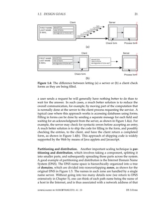
![1.2. DESIGN GOALS 23
caching results in making a copy of a resource, generally in the proximity of
the client accessing that resource. However, in contrast to replication, caching
is a decision made by the client of a resource and not by the owner of a
resource.
There is one serious drawback to caching and replication that may ad-
versely affect scalability. Because we now have multiple copies of a resource,
modifying one copy makes that copy different from the others. Consequently,
caching and replication leads to consistency problems.
To what extent inconsistencies can be tolerated depends highly on the
usage of a resource. For example, many Web users find it acceptable that
their browser returns a cached document of which the validity has not been
checked for the last few minutes. However, there are also many cases in which
strong consistency guarantees need to be met, such as in the case of electronic
stock exchanges and auctions. The problem with strong consistency is that
an update must be immediately propagated to all other copies. Moreover, if
two updates happen concurrently, it is often also required that updates are
processed in the same order everywhere, introducing an additional global
ordering problem. To further aggravate problems, combining consistency with
other desirable properties such as availability may simply be impossible, as
we discuss in Chapter 8.
Replication therefore often requires some global synchronization mecha-
nism. Unfortunately, such mechanisms are extremely hard or even impossible
to implement in a scalable way, if alone because network latencies have a nat-
ural lower bound. Consequently, scaling by replication may introduce other,
inherently nonscalable solutions. We return to replication and consistency
extensively in Chapter 7.
Discussion. When considering these scaling techniques, one could argue
that size scalability is the least problematic from a technical point of view. In
many cases, increasing the capacity of a machine will save the day, although
perhaps there is a high monetary cost to pay. Geographical scalability is a
much tougher problem as network latencies are naturally bound from below.
As a consequence, we may be forced to copy data to locations close to where
clients are, leading to problems of maintaining copies consistent. Practice
shows that combining distribution, replication, and caching techniques with
different forms of consistency generally leads to acceptable solutions. Finally,
administrative scalability seems to be the most difficult problem to solve,
partly because we need to deal with nontechnical issues, such as politics of or-
ganizations and human collaboration. The introduction and now widespread
use of peer-to-peer technology has successfully demonstrated what can be
achieved if end users are put in control [Lua et al., 2005; Oram, 2001]. How-
ever, peer-to-peer networks are obviously not the universal solution to all
administrative scalability problems.
downloaded by HUSNI@TRUNOJOYO.AC.ID DS 3.01pre
1.2. DESIGN GOALS 23
caching results in making a copy of a resource, generally in the proximity of
the client accessing that resource. However, in contrast to replication, caching
is a decision made by the client of a resource and not by the owner of a
resource.
There is one serious drawback to caching and replication that may ad-
versely affect scalability. Because we now have multiple copies of a resource,
modifying one copy makes that copy different from the others. Consequently,
caching and replication leads to consistency problems.
To what extent inconsistencies can be tolerated depends highly on the
usage of a resource. For example, many Web users find it acceptable that
their browser returns a cached document of which the validity has not been
checked for the last few minutes. However, there are also many cases in which
strong consistency guarantees need to be met, such as in the case of electronic
stock exchanges and auctions. The problem with strong consistency is that
an update must be immediately propagated to all other copies. Moreover, if
two updates happen concurrently, it is often also required that updates are
processed in the same order everywhere, introducing an additional global
ordering problem. To further aggravate problems, combining consistency with
other desirable properties such as availability may simply be impossible, as
we discuss in Chapter 8.
Replication therefore often requires some global synchronization mecha-
nism. Unfortunately, such mechanisms are extremely hard or even impossible
to implement in a scalable way, if alone because network latencies have a nat-
ural lower bound. Consequently, scaling by replication may introduce other,
inherently nonscalable solutions. We return to replication and consistency
extensively in Chapter 7.
Discussion. When considering these scaling techniques, one could argue
that size scalability is the least problematic from a technical point of view. In
many cases, increasing the capacity of a machine will save the day, although
perhaps there is a high monetary cost to pay. Geographical scalability is a
much tougher problem as network latencies are naturally bound from below.
As a consequence, we may be forced to copy data to locations close to where
clients are, leading to problems of maintaining copies consistent. Practice
shows that combining distribution, replication, and caching techniques with
different forms of consistency generally leads to acceptable solutions. Finally,
administrative scalability seems to be the most difficult problem to solve,
partly because we need to deal with nontechnical issues, such as politics of or-
ganizations and human collaboration. The introduction and now widespread
use of peer-to-peer technology has successfully demonstrated what can be
achieved if end users are put in control [Lua et al., 2005; Oram, 2001]. How-
ever, peer-to-peer networks are obviously not the universal solution to all
administrative scalability problems.
downloaded by HUSNI@TRUNOJOYO.AC.ID DS 3.01pre](https://image.slidesharecdn.com/distributed-systems-3rd-edition-251215232331-7e034da0/85/architectureec-distributed-systems-3rd-Edition-pdf-37-320.jpg)
![1.3. TYPES OF DISTRIBUTED SYSTEMS 25
distinction between distributed computing systems, distributed information
systems, and pervasive systems (which are naturally distributed).
High performance distributed computing
An important class of distributed systems is the one used for high-performance
computing tasks. Roughly speaking, one can make a distinction between two
subgroups. In cluster computing the underlying hardware consists of a
collection of similar workstations or PCs, closely connected by means of a
high-speed local-area network. In addition, each node runs the same operating
system.
The situation becomes very different in the case of grid computing. This
subgroup consists of distributed systems that are often constructed as a
federation of computer systems, where each system may fall under a different
administrative domain, and may be very different when it comes to hardware,
software, and deployed network technology.
From the perspective of grid computing, a next logical step is to simply
outsource the entire infrastructure that is needed for compute-intensive ap-
plications. In essence, this is what cloud computing is all about: providing
the facilities to dynamically construct an infrastructure and compose what
is needed from available services. Unlike grid computing, which is strongly
associated with high-performance computing, cloud computing is much more
than just providing lots of resources. We discuss it briefly here, but will return
to various aspects throughout the book.
Note 1.8 (More information: Parallel processing)
High-performance computing more or less started with the introduction of mul-
tiprocessor machines. In this case, multiple CPUs are organized in such a way
that they all have access to the same physical memory, as shown in Figure 1.6(a).
In contrast, in a multicomputer system several computers are connected through
a network and there is no sharing of main memory, as shown in Figure 1.6(b).
The shared-memory model proved to be highly convenient for improving the
performance of programs and it was relatively easy to program.
Its essence is that multiple threads of control are executing at the same time,
while all threads have access to shared data. Access to that data is controlled
through well-understood synchronization mechanisms like semaphores (see Ben-
Ari [2006] or Herlihy and Shavit [2008] for more information on developing
parallel programs). Unfortunately, the model does not easily scale: so far, ma-
chines have been developed in which only a few tens (and sometimes hundreds)
of CPUs have efficient access to shared memory. To a certain extent, we are seeing
the same limitations for multicore processors.
downloaded by HUSNI@TRUNOJOYO.AC.ID DS 3.01pre
1.3. TYPES OF DISTRIBUTED SYSTEMS 25
distinction between distributed computing systems, distributed information
systems, and pervasive systems (which are naturally distributed).
High performance distributed computing
An important class of distributed systems is the one used for high-performance
computing tasks. Roughly speaking, one can make a distinction between two
subgroups. In cluster computing the underlying hardware consists of a
collection of similar workstations or PCs, closely connected by means of a
high-speed local-area network. In addition, each node runs the same operating
system.
The situation becomes very different in the case of grid computing. This
subgroup consists of distributed systems that are often constructed as a
federation of computer systems, where each system may fall under a different
administrative domain, and may be very different when it comes to hardware,
software, and deployed network technology.
From the perspective of grid computing, a next logical step is to simply
outsource the entire infrastructure that is needed for compute-intensive ap-
plications. In essence, this is what cloud computing is all about: providing
the facilities to dynamically construct an infrastructure and compose what
is needed from available services. Unlike grid computing, which is strongly
associated with high-performance computing, cloud computing is much more
than just providing lots of resources. We discuss it briefly here, but will return
to various aspects throughout the book.
Note 1.8 (More information: Parallel processing)
High-performance computing more or less started with the introduction of mul-
tiprocessor machines. In this case, multiple CPUs are organized in such a way
that they all have access to the same physical memory, as shown in Figure 1.6(a).
In contrast, in a multicomputer system several computers are connected through
a network and there is no sharing of main memory, as shown in Figure 1.6(b).
The shared-memory model proved to be highly convenient for improving the
performance of programs and it was relatively easy to program.
Its essence is that multiple threads of control are executing at the same time,
while all threads have access to shared data. Access to that data is controlled
through well-understood synchronization mechanisms like semaphores (see Ben-
Ari [2006] or Herlihy and Shavit [2008] for more information on developing
parallel programs). Unfortunately, the model does not easily scale: so far, ma-
chines have been developed in which only a few tens (and sometimes hundreds)
of CPUs have efficient access to shared memory. To a certain extent, we are seeing
the same limitations for multicore processors.
downloaded by HUSNI@TRUNOJOYO.AC.ID DS 3.01pre](https://image.slidesharecdn.com/distributed-systems-3rd-edition-251215232331-7e034da0/85/architectureec-distributed-systems-3rd-Edition-pdf-39-320.jpg)
![26 CHAPTER 1. INTRODUCTION
(a) (b)
Figure 1.6: A comparison between (a) multiprocessor and (b) multicom-
puter architectures.
To overcome the limitations of shared-memory systems, high-performance
computing moved to distributed-memory systems. This shift also meant that many
programs had to make use of message passing instead of modifying shared data as
a means of communication and synchronization between threads. Unfortunately,
message-passing models have proven to be much more difficult and error-prone
compared to the shared-memory programming models. For this reason, there
has been significant research in attempting to build so-called distributed shared-
memory multicomputers, or simply DSM system [Amza et al., 1996].
In essence, a DSM system allows a processor to address a memory location
at another computer as if it were local memory. This can be achieved using
existing techniques available to the operating system, for example, by mapping all
main-memory pages of the various processors into a single virtual address space.
Whenever a processor A addresses a page located at another processor B, a page
fault occurs at A allowing the operating system at A to fetch the content of the
referenced page at B in the same way that it would normally fetch it locally from
disk. At the same time, processor B would be informed that the page is currently
not accessible.
This elegant idea of mimicking shared-memory systems using multicomputers
eventually had to be abandoned for the simple reason that performance could
never meet the expectations of programmers, who would rather resort to far
more intricate, yet better (predictably) performing message-passing programming
models.
An important side-effect of exploring the hardware-software boundaries of
parallel processing is a thorough understanding of consistency models, to which
we return extensively in Chapter 7.
Cluster computing
Cluster computing systems became popular when the price/performance
ratio of personal computers and workstations improved. At a certain point, it
became financially and technically attractive to build a supercomputer using
off-the-shelf technology by simply hooking up a collection of relatively simple
computers in a high-speed network. In virtually all cases, cluster computing is
DS 3.01pre downloaded by HUSNI@TRUNOJOYO.AC.ID
26 CHAPTER 1. INTRODUCTION
(a) (b)
Figure 1.6: A comparison between (a) multiprocessor and (b) multicom-
puter architectures.
To overcome the limitations of shared-memory systems, high-performance
computing moved to distributed-memory systems. This shift also meant that many
programs had to make use of message passing instead of modifying shared data as
a means of communication and synchronization between threads. Unfortunately,
message-passing models have proven to be much more difficult and error-prone
compared to the shared-memory programming models. For this reason, there
has been significant research in attempting to build so-called distributed shared-
memory multicomputers, or simply DSM system [Amza et al., 1996].
In essence, a DSM system allows a processor to address a memory location
at another computer as if it were local memory. This can be achieved using
existing techniques available to the operating system, for example, by mapping all
main-memory pages of the various processors into a single virtual address space.
Whenever a processor A addresses a page located at another processor B, a page
fault occurs at A allowing the operating system at A to fetch the content of the
referenced page at B in the same way that it would normally fetch it locally from
disk. At the same time, processor B would be informed that the page is currently
not accessible.
This elegant idea of mimicking shared-memory systems using multicomputers
eventually had to be abandoned for the simple reason that performance could
never meet the expectations of programmers, who would rather resort to far
more intricate, yet better (predictably) performing message-passing programming
models.
An important side-effect of exploring the hardware-software boundaries of
parallel processing is a thorough understanding of consistency models, to which
we return extensively in Chapter 7.
Cluster computing
Cluster computing systems became popular when the price/performance
ratio of personal computers and workstations improved. At a certain point, it
became financially and technically attractive to build a supercomputer using
off-the-shelf technology by simply hooking up a collection of relatively simple
computers in a high-speed network. In virtually all cases, cluster computing is
DS 3.01pre downloaded by HUSNI@TRUNOJOYO.AC.ID](https://image.slidesharecdn.com/distributed-systems-3rd-edition-251215232331-7e034da0/85/architectureec-distributed-systems-3rd-Edition-pdf-40-320.jpg)
![1.3. TYPES OF DISTRIBUTED SYSTEMS 27
used for parallel programming in which a single (compute intensive) program
is run in parallel on multiple machines.
Figure 1.7: An example of a cluster computing system.
One widely applied example of a cluster computer is formed by Linux-
based Beowulf clusters, of which the general configuration is shown in Fig-
ure 1.7. Each cluster consists of a collection of compute nodes that are con-
trolled and accessed by means of a single master node. The master typically
handles the allocation of nodes to a particular parallel program, maintains
a batch queue of submitted jobs, and provides an interface for the users of
the system. As such, the master actually runs the middleware needed for the
execution of programs and management of the cluster, while the compute
nodes are equipped with a standard operating system extended with typical
middleware functions for communication, storage, fault tolerance, and so on.
Apart from the master node, the compute nodes are thus seen to be highly
identical.
An even more symmetric approach is followed in the MOSIX system [Amar
et al., 2004]. MOSIX attempts to provide a single-system image of a cluster,
meaning that to a process a cluster computer offers the ultimate distribution
transparency by appearing to be a single computer. As we mentioned, pro-
viding such an image under all circumstances is impossible. In the case of
MOSIX, the high degree of transparency is provided by allowing processes
to dynamically and preemptively migrate between the nodes that make up
the cluster. Process migration allows a user to start an application on any
node (referred to as the home node), after which it can transparently move to
other nodes, for example, to make efficient use of resources. We will return to
process migration in Chapter 3. Similar approaches at attempting to provide
a single-system image are compared by [Lottiaux et al., 2005].
However, several modern cluster computers have been moving away from
these symmetric architectures to more hybrid solutions in which the middle-
ware is functionally partitioned across different nodes, as explained by En-
gelmann et al. [2007]. The advantage of such a separation is obvious: having
downloaded by HUSNI@TRUNOJOYO.AC.ID DS 3.01pre
1.3. TYPES OF DISTRIBUTED SYSTEMS 27
used for parallel programming in which a single (compute intensive) program
is run in parallel on multiple machines.
Figure 1.7: An example of a cluster computing system.
One widely applied example of a cluster computer is formed by Linux-
based Beowulf clusters, of which the general configuration is shown in Fig-
ure 1.7. Each cluster consists of a collection of compute nodes that are con-
trolled and accessed by means of a single master node. The master typically
handles the allocation of nodes to a particular parallel program, maintains
a batch queue of submitted jobs, and provides an interface for the users of
the system. As such, the master actually runs the middleware needed for the
execution of programs and management of the cluster, while the compute
nodes are equipped with a standard operating system extended with typical
middleware functions for communication, storage, fault tolerance, and so on.
Apart from the master node, the compute nodes are thus seen to be highly
identical.
An even more symmetric approach is followed in the MOSIX system [Amar
et al., 2004]. MOSIX attempts to provide a single-system image of a cluster,
meaning that to a process a cluster computer offers the ultimate distribution
transparency by appearing to be a single computer. As we mentioned, pro-
viding such an image under all circumstances is impossible. In the case of
MOSIX, the high degree of transparency is provided by allowing processes
to dynamically and preemptively migrate between the nodes that make up
the cluster. Process migration allows a user to start an application on any
node (referred to as the home node), after which it can transparently move to
other nodes, for example, to make efficient use of resources. We will return to
process migration in Chapter 3. Similar approaches at attempting to provide
a single-system image are compared by [Lottiaux et al., 2005].
However, several modern cluster computers have been moving away from
these symmetric architectures to more hybrid solutions in which the middle-
ware is functionally partitioned across different nodes, as explained by En-
gelmann et al. [2007]. The advantage of such a separation is obvious: having
downloaded by HUSNI@TRUNOJOYO.AC.ID DS 3.01pre](https://image.slidesharecdn.com/distributed-systems-3rd-edition-251215232331-7e034da0/85/architectureec-distributed-systems-3rd-Edition-pdf-41-320.jpg)
![28 CHAPTER 1. INTRODUCTION
compute nodes with dedicated, lightweight operating systems will most likely
provide optimal performance for compute-intensive applications. Likewise,
storage functionality can most likely be optimally handled by other specially
configured nodes such as file and directory servers. The same holds for other
dedicated middleware services, including job management, database services,
and perhaps general Internet access to external services.
Grid computing
A characteristic feature of traditional cluster computing is its homogeneity.
In most cases, the computers in a cluster are largely the same, have the
same operating system, and are all connected through the same network.
However, as we just discussed, there has been a trend towards more hybrid
architectures in which nodes are specifically configured for certain tasks. This
diversity is even more prevalent in grid computing systems: no assumptions
are made concerning similarity of hardware, operating systems, networks,
administrative domains, security policies, etc.
A key issue in a grid-computing system is that resources from different
organizations are brought together to allow the collaboration of a group of
people from different institutions, indeed forming a federation of systems.
Such a collaboration is realized in the form of a virtual organization. The
processes belonging to the same virtual organization have access rights to the
resources that are provided to that organization. Typically, resources consist of
compute servers (including supercomputers, possibly implemented as cluster
computers), storage facilities, and databases. In addition, special networked
devices such as telescopes, sensors, etc., can be provided as well.
Given its nature, much of the software for realizing grid computing evolves
around providing access to resources from different administrative domains,
and to only those users and applications that belong to a specific virtual
organization. For this reason, focus is often on architectural issues. An
architecture initially proposed by Foster et al. [2001] is shown in Figure 1.8,
which still forms the basis for many grid computing systems.
Figure 1.8: A layered architecture for grid computing systems.
DS 3.01pre downloaded by HUSNI@TRUNOJOYO.AC.ID
28 CHAPTER 1. INTRODUCTION
compute nodes with dedicated, lightweight operating systems will most likely
provide optimal performance for compute-intensive applications. Likewise,
storage functionality can most likely be optimally handled by other specially
configured nodes such as file and directory servers. The same holds for other
dedicated middleware services, including job management, database services,
and perhaps general Internet access to external services.
Grid computing
A characteristic feature of traditional cluster computing is its homogeneity.
In most cases, the computers in a cluster are largely the same, have the
same operating system, and are all connected through the same network.
However, as we just discussed, there has been a trend towards more hybrid
architectures in which nodes are specifically configured for certain tasks. This
diversity is even more prevalent in grid computing systems: no assumptions
are made concerning similarity of hardware, operating systems, networks,
administrative domains, security policies, etc.
A key issue in a grid-computing system is that resources from different
organizations are brought together to allow the collaboration of a group of
people from different institutions, indeed forming a federation of systems.
Such a collaboration is realized in the form of a virtual organization. The
processes belonging to the same virtual organization have access rights to the
resources that are provided to that organization. Typically, resources consist of
compute servers (including supercomputers, possibly implemented as cluster
computers), storage facilities, and databases. In addition, special networked
devices such as telescopes, sensors, etc., can be provided as well.
Given its nature, much of the software for realizing grid computing evolves
around providing access to resources from different administrative domains,
and to only those users and applications that belong to a specific virtual
organization. For this reason, focus is often on architectural issues. An
architecture initially proposed by Foster et al. [2001] is shown in Figure 1.8,
which still forms the basis for many grid computing systems.
Figure 1.8: A layered architecture for grid computing systems.
DS 3.01pre downloaded by HUSNI@TRUNOJOYO.AC.ID](https://image.slidesharecdn.com/distributed-systems-3rd-edition-251215232331-7e034da0/85/architectureec-distributed-systems-3rd-Edition-pdf-42-320.jpg)
![1.3. TYPES OF DISTRIBUTED SYSTEMS 29
The architecture consists of four layers. The lowest fabric layer provides
interfaces to local resources at a specific site. Note that these interfaces are
tailored to allow sharing of resources within a virtual organization. Typically,
they will provide functions for querying the state and capabilities of a resource,
along with functions for actual resource management (e.g., locking resources).
The connectivity layer consists of communication protocols for supporting
grid transactions that span the usage of multiple resources. For example,
protocols are needed to transfer data between resources, or to simply access
a resource from a remote location. In addition, the connectivity layer will
contain security protocols to authenticate users and resources. Note that in
many cases human users are not authenticated; instead, programs acting on
behalf of the users are authenticated. In this sense, delegating rights from
a user to programs is an important function that needs to be supported in
the connectivity layer. We return to delegation when discussing security in
distributed systems in Chapter 9.
The resource layer is responsible for managing a single resource. It uses the
functions provided by the connectivity layer and calls directly the interfaces
made available by the fabric layer. For example, this layer will offer functions
for obtaining configuration information on a specific resource, or, in general,
to perform specific operations such as creating a process or reading data. The
resource layer is thus seen to be responsible for access control, and hence will
rely on the authentication performed as part of the connectivity layer.
The next layer in the hierarchy is the collective layer. It deals with handling
access to multiple resources and typically consists of services for resource
discovery, allocation and scheduling of tasks onto multiple resources, data
replication, and so on. Unlike the connectivity and resource layer, each
consisting of a relatively small, standard collection of protocols, the collective
layer may consist of many different protocols reflecting the broad spectrum of
services it may offer to a virtual organization.
Finally, the application layer consists of the applications that operate within a
virtual organization and which make use of the grid computing environment.
Typically the collective, connectivity, and resource layer form the heart of
what could be called a grid middleware layer. These layers jointly provide
access to and management of resources that are potentially dispersed across
multiple sites.
An important observation from a middleware perspective is that in grid
computing the notion of a site (or administrative unit) is common. This
prevalence is emphasized by the gradual shift toward a service-oriented ar-
chitecture in which sites offer access to the various layers through a collection
of Web services [Joseph et al., 2004]. This, by now, has lead to the definition
of an alternative architecture known as the Open Grid Services Architecture
(OGSA) [Foster et al., 2006]. OGSA is based upon the original ideas as for-
mulated by Foster et al. [2001], yet having gone through a standardization
downloaded by HUSNI@TRUNOJOYO.AC.ID DS 3.01pre
1.3. TYPES OF DISTRIBUTED SYSTEMS 29
The architecture consists of four layers. The lowest fabric layer provides
interfaces to local resources at a specific site. Note that these interfaces are
tailored to allow sharing of resources within a virtual organization. Typically,
they will provide functions for querying the state and capabilities of a resource,
along with functions for actual resource management (e.g., locking resources).
The connectivity layer consists of communication protocols for supporting
grid transactions that span the usage of multiple resources. For example,
protocols are needed to transfer data between resources, or to simply access
a resource from a remote location. In addition, the connectivity layer will
contain security protocols to authenticate users and resources. Note that in
many cases human users are not authenticated; instead, programs acting on
behalf of the users are authenticated. In this sense, delegating rights from
a user to programs is an important function that needs to be supported in
the connectivity layer. We return to delegation when discussing security in
distributed systems in Chapter 9.
The resource layer is responsible for managing a single resource. It uses the
functions provided by the connectivity layer and calls directly the interfaces
made available by the fabric layer. For example, this layer will offer functions
for obtaining configuration information on a specific resource, or, in general,
to perform specific operations such as creating a process or reading data. The
resource layer is thus seen to be responsible for access control, and hence will
rely on the authentication performed as part of the connectivity layer.
The next layer in the hierarchy is the collective layer. It deals with handling
access to multiple resources and typically consists of services for resource
discovery, allocation and scheduling of tasks onto multiple resources, data
replication, and so on. Unlike the connectivity and resource layer, each
consisting of a relatively small, standard collection of protocols, the collective
layer may consist of many different protocols reflecting the broad spectrum of
services it may offer to a virtual organization.
Finally, the application layer consists of the applications that operate within a
virtual organization and which make use of the grid computing environment.
Typically the collective, connectivity, and resource layer form the heart of
what could be called a grid middleware layer. These layers jointly provide
access to and management of resources that are potentially dispersed across
multiple sites.
An important observation from a middleware perspective is that in grid
computing the notion of a site (or administrative unit) is common. This
prevalence is emphasized by the gradual shift toward a service-oriented ar-
chitecture in which sites offer access to the various layers through a collection
of Web services [Joseph et al., 2004]. This, by now, has lead to the definition
of an alternative architecture known as the Open Grid Services Architecture
(OGSA) [Foster et al., 2006]. OGSA is based upon the original ideas as for-
mulated by Foster et al. [2001], yet having gone through a standardization
downloaded by HUSNI@TRUNOJOYO.AC.ID DS 3.01pre](https://image.slidesharecdn.com/distributed-systems-3rd-edition-251215232331-7e034da0/85/architectureec-distributed-systems-3rd-Edition-pdf-43-320.jpg)
![30 CHAPTER 1. INTRODUCTION
process makes it complex, to say the least. OGSA implementations generally
follow Web service standards.
Cloud computing
While researchers were pondering on how to organize computational grids
that were easily accessible, organizations in charge of running data centers
were facing the problem of opening up their resources to customers. Eventu-
ally, this lead to the concept of utility computing by which a customer could
upload tasks to a data center and be charged on a per-resource basis. Utility
computing formed the basis for what is now called cloud computing.
Following Vaquero et al. [2008], cloud computing is characterized by an
easily usable and accessible pool of virtualized resources. Which and how
resources are used can be configured dynamically, providing the basis for
scalability: if more work needs to be done, a customer can simply acquire
more resources. The link to utility computing is formed by the fact that cloud
computing is generally based on a pay-per-use model in which guarantees
are offered by means of customized service level agreements (SLAs).
Figure 1.9: The organization of clouds (adapted from Zhang et al. [2010]).
In practice, clouds are organized into four layers, as shown in Figure 1.9
(see also Zhang et al. [2010]):
Hardware: The lowest layer is formed by the means to manage the necessary
hardware: processors, routers, but also power and cooling systems. It is
generally implemented at data centers and contains the resources that
customers normally never get to see directly.
Infrastructure: This is an important layer forming the backbone for most
cloud computing platforms. It deploys virtualization techniques (dis-
cussed in Section 3.2) to provide customers an infrastructure consisting
DS 3.01pre downloaded by HUSNI@TRUNOJOYO.AC.ID
30 CHAPTER 1. INTRODUCTION
process makes it complex, to say the least. OGSA implementations generally
follow Web service standards.
Cloud computing
While researchers were pondering on how to organize computational grids
that were easily accessible, organizations in charge of running data centers
were facing the problem of opening up their resources to customers. Eventu-
ally, this lead to the concept of utility computing by which a customer could
upload tasks to a data center and be charged on a per-resource basis. Utility
computing formed the basis for what is now called cloud computing.
Following Vaquero et al. [2008], cloud computing is characterized by an
easily usable and accessible pool of virtualized resources. Which and how
resources are used can be configured dynamically, providing the basis for
scalability: if more work needs to be done, a customer can simply acquire
more resources. The link to utility computing is formed by the fact that cloud
computing is generally based on a pay-per-use model in which guarantees
are offered by means of customized service level agreements (SLAs).
Figure 1.9: The organization of clouds (adapted from Zhang et al. [2010]).
In practice, clouds are organized into four layers, as shown in Figure 1.9
(see also Zhang et al. [2010]):
Hardware: The lowest layer is formed by the means to manage the necessary
hardware: processors, routers, but also power and cooling systems. It is
generally implemented at data centers and contains the resources that
customers normally never get to see directly.
Infrastructure: This is an important layer forming the backbone for most
cloud computing platforms. It deploys virtualization techniques (dis-
cussed in Section 3.2) to provide customers an infrastructure consisting
DS 3.01pre downloaded by HUSNI@TRUNOJOYO.AC.ID](https://image.slidesharecdn.com/distributed-systems-3rd-edition-251215232331-7e034da0/85/architectureec-distributed-systems-3rd-Edition-pdf-44-320.jpg)
![1.3. TYPES OF DISTRIBUTED SYSTEMS 31
of virtual storage and computing resources. Indeed, nothing is what
it seems: cloud computing evolves around allocating and managing
virtual storage devices and virtual servers.
Platform: One could argue that the platform layer provides to a cloud-
computing customer what an operating system provides to application
developers, namely the means to easily develop and deploy applications
that need to run in a cloud. In practice, an application developer is
offered a vendor-specific API, which includes calls to uploading and ex-
ecuting a program in that vendor’s cloud. In a sense, this is comparable
the Unix exec family of system calls, which take an executable file as
parameter and pass it to the operating system to be executed.
Also like operating systems, the platform layer provides higher-level
abstractions for storage and such. For example, as we discuss in more
detail later, the Amazon S3 storage system [Murty, 2008] is offered to the
application developer in the form of an API allowing (locally created)
files to be organized and stored in buckets. A bucket is somewhat
comparable to a directory. By storing a file in a bucket, that file is
automatically uploaded to the Amazon cloud.
Application: Actual applications run in this layer and are offered to users
for further customization. Well-known examples include those found
in office suites (text processors, spreadsheet applications, presentation
applications, and so on). It is important to realize that these applica-
tions are again executed in the vendor’s cloud. As before, they can be
compared to the traditional suite of applications that are shipped when
installing an operating system.
Cloud-computing providers offer these layers to their customers through
various interfaces (including command-line tools, programming interfaces,
and Web interfaces), leading to three different types of services:
• Infrastructure-as-a-Service (IaaS) covering the hardware and infrastructure
layer
• Platform-as-a-Service (PaaS) covering the platform layer
• Software-as-a-Service (SaaS) in which their applications are covered
As of now, making use of clouds is relatively easy, and we discuss in later
chapters more concrete examples of interfaces to cloud providers. As a
consequence, cloud computing as a means for outsourcing local computing
infrastructures has become a serious option for many enterprises. However,
there are still a number of serious obstacles including provider lock-in, security
and privacy issues, and dependency on the availability of services, to mention
a few (see also Armbrust et al. [2010]). Also, because the details on how
specific cloud computations are actually carried out are generally hidden, and
downloaded by HUSNI@TRUNOJOYO.AC.ID DS 3.01pre
1.3. TYPES OF DISTRIBUTED SYSTEMS 31
of virtual storage and computing resources. Indeed, nothing is what
it seems: cloud computing evolves around allocating and managing
virtual storage devices and virtual servers.
Platform: One could argue that the platform layer provides to a cloud-
computing customer what an operating system provides to application
developers, namely the means to easily develop and deploy applications
that need to run in a cloud. In practice, an application developer is
offered a vendor-specific API, which includes calls to uploading and ex-
ecuting a program in that vendor’s cloud. In a sense, this is comparable
the Unix exec family of system calls, which take an executable file as
parameter and pass it to the operating system to be executed.
Also like operating systems, the platform layer provides higher-level
abstractions for storage and such. For example, as we discuss in more
detail later, the Amazon S3 storage system [Murty, 2008] is offered to the
application developer in the form of an API allowing (locally created)
files to be organized and stored in buckets. A bucket is somewhat
comparable to a directory. By storing a file in a bucket, that file is
automatically uploaded to the Amazon cloud.
Application: Actual applications run in this layer and are offered to users
for further customization. Well-known examples include those found
in office suites (text processors, spreadsheet applications, presentation
applications, and so on). It is important to realize that these applica-
tions are again executed in the vendor’s cloud. As before, they can be
compared to the traditional suite of applications that are shipped when
installing an operating system.
Cloud-computing providers offer these layers to their customers through
various interfaces (including command-line tools, programming interfaces,
and Web interfaces), leading to three different types of services:
• Infrastructure-as-a-Service (IaaS) covering the hardware and infrastructure
layer
• Platform-as-a-Service (PaaS) covering the platform layer
• Software-as-a-Service (SaaS) in which their applications are covered
As of now, making use of clouds is relatively easy, and we discuss in later
chapters more concrete examples of interfaces to cloud providers. As a
consequence, cloud computing as a means for outsourcing local computing
infrastructures has become a serious option for many enterprises. However,
there are still a number of serious obstacles including provider lock-in, security
and privacy issues, and dependency on the availability of services, to mention
a few (see also Armbrust et al. [2010]). Also, because the details on how
specific cloud computations are actually carried out are generally hidden, and
downloaded by HUSNI@TRUNOJOYO.AC.ID DS 3.01pre](https://image.slidesharecdn.com/distributed-systems-3rd-edition-251215232331-7e034da0/85/architectureec-distributed-systems-3rd-Edition-pdf-45-320.jpg)
![32 CHAPTER 1. INTRODUCTION
even perhaps unknown or unpredictable, meeting performance demands may
be impossible to arrange in advance. On top of this, Li et al. [2010] have shown
that different providers may easily show very different performance profiles.
Cloud computing is no longer a hype, and certainly a serious alternative
to maintaining huge local infrastructures, yet there is still a lot of room for
improvement.
Note 1.9 (Advanced: Is cloud computing cheaper?)
One of the important reasons to migrate to a cloud environment is that it may be
much cheaper compared to maintaining a local computing infrastructure. There
are many ways to compute the savings, but as it turns out, only for simple and
obvious cases will straightforward computations give a realistic perspective. Hajjat
et al. [2010] propose a more thorough approach, taking into account that part of
an application suite is migrated to a cloud, and the other part continues to be
operated on a local infrastructure. The crux of their method is providing the right
model of a suite of enterprise applications.
The core of their approach is formed by a potentially large set of software
components. Each enterprise application is assumed to consist of components.
Furthermore, each component Ci is considered to be run on Ni servers. A simple
example is a database component to be executed by a single server. A more
elaborate example is a Web application for computing bicycle routes, consisting
of a Web server front end for rendering HTML pages and accepting user input, a
component for computing shortest paths (perhaps under different constraints),
and a database component containing various maps.
Each application is modeled as a directed graph, in which a vertex represents
a component and an arc h
−
→
i, ji the fact that data flows from component Ci to
component Cj. Each arc has two associated weights: Ti,j represents the number of
transactions per time unit leading to data flowing from Ci to Cj, and Si,j the average
size of those transactions (i.e., the average amount of data per transaction). They
assume that Ti,j and Si,j are known, typically obtained through straightforward
measurements.
Migrating a suite of applications from a local infrastructure to the cloud
then boils down to finding an optimal migration plan M: figuring out for each
component Ci, how many ni of its Ni servers should be moved to the cloud, such
that the monetary benefits resulting from M, reduced by the additional costs for
communicating over the Internet, are maximal. A plan M should also meet the
following constraints:
1. Policy constraints are met. For example, there may be data that is legally
required to be located at an organization’s local infrastructure.
2. Because communication is now partly across long-haul Internet links, it may
be that certain transactions between components become much slower. A
plan M is acceptable only if any additional latencies do not violate specific
delay constraints.
3. Flow balance equations should be respected: transactions continue to
operate correctly, and requests or data are not lost during a transaction.
DS 3.01pre downloaded by HUSNI@TRUNOJOYO.AC.ID
32 CHAPTER 1. INTRODUCTION
even perhaps unknown or unpredictable, meeting performance demands may
be impossible to arrange in advance. On top of this, Li et al. [2010] have shown
that different providers may easily show very different performance profiles.
Cloud computing is no longer a hype, and certainly a serious alternative
to maintaining huge local infrastructures, yet there is still a lot of room for
improvement.
Note 1.9 (Advanced: Is cloud computing cheaper?)
One of the important reasons to migrate to a cloud environment is that it may be
much cheaper compared to maintaining a local computing infrastructure. There
are many ways to compute the savings, but as it turns out, only for simple and
obvious cases will straightforward computations give a realistic perspective. Hajjat
et al. [2010] propose a more thorough approach, taking into account that part of
an application suite is migrated to a cloud, and the other part continues to be
operated on a local infrastructure. The crux of their method is providing the right
model of a suite of enterprise applications.
The core of their approach is formed by a potentially large set of software
components. Each enterprise application is assumed to consist of components.
Furthermore, each component Ci is considered to be run on Ni servers. A simple
example is a database component to be executed by a single server. A more
elaborate example is a Web application for computing bicycle routes, consisting
of a Web server front end for rendering HTML pages and accepting user input, a
component for computing shortest paths (perhaps under different constraints),
and a database component containing various maps.
Each application is modeled as a directed graph, in which a vertex represents
a component and an arc h
−
→
i, ji the fact that data flows from component Ci to
component Cj. Each arc has two associated weights: Ti,j represents the number of
transactions per time unit leading to data flowing from Ci to Cj, and Si,j the average
size of those transactions (i.e., the average amount of data per transaction). They
assume that Ti,j and Si,j are known, typically obtained through straightforward
measurements.
Migrating a suite of applications from a local infrastructure to the cloud
then boils down to finding an optimal migration plan M: figuring out for each
component Ci, how many ni of its Ni servers should be moved to the cloud, such
that the monetary benefits resulting from M, reduced by the additional costs for
communicating over the Internet, are maximal. A plan M should also meet the
following constraints:
1. Policy constraints are met. For example, there may be data that is legally
required to be located at an organization’s local infrastructure.
2. Because communication is now partly across long-haul Internet links, it may
be that certain transactions between components become much slower. A
plan M is acceptable only if any additional latencies do not violate specific
delay constraints.
3. Flow balance equations should be respected: transactions continue to
operate correctly, and requests or data are not lost during a transaction.
DS 3.01pre downloaded by HUSNI@TRUNOJOYO.AC.ID](https://image.slidesharecdn.com/distributed-systems-3rd-edition-251215232331-7e034da0/85/architectureec-distributed-systems-3rd-Edition-pdf-46-320.jpg)
![1.3. TYPES OF DISTRIBUTED SYSTEMS 33
Let us now look into the benefits and Internet costs of a migration plan.
Benefits For each migration plan M, one can expect to have monetary savings
expressed as Benefits(M), because fewer machines or network connections need to
be maintained. In many organizations, such costs are known so that it may be
relatively simple to compute the savings. On the other hand, there are costs to
be made for using the cloud. Hajjat et al. [2010] make a simplifying distinction
between the benefit Bc of migrating a compute-intensive component, and the
benefit Bs of migrating a storage-intensive component. If there are Mc compute-
intensive and Ms storage-intensive components, we have Benefits(M) = Bc · Mc +
Bs · Ms. Obviously, much more sophisticated models can be deployed as well.
Internet costs To compute the increased communication costs because com-
ponents are spread across the cloud as well as the local infrastructure, we need
to take user-initiated requests into account. To simplify matters, we make no
distinction between internal users (i.e., members of the enterprise), and external
users (as one would see in the case of Web applications). Traffic from users before
migration can be expressed as:
Trlocal,inet = ∑
Ci
(Tuser,iSuser,i + Ti,userSi,user)
where Tuser,i denotes the number of transactions per time unit leading to data
flowing from users to Ci. We have analogous interpretations for Ti,user, Suseri , and
Si,user.
For each component Ci, let Ci,local denote the servers that continue to operate
on the local infrastructure, and Ci,cloud its servers that are placed in the cloud. Note
that |Ci,cloud| = ni. For simplicity, assume that a server from Ci,local distributes
traffic in the same proportions as a server from Ci,cloud. We are interested in
the rate of transactions between local servers, cloud servers, and between local
and cloud servers, after migration. Let sk be the server for component Ck and
denote by fk the fraction nk/Nk. We then have for the rate of transactions T∗
i,j after
migration:
T∗
i,j =
(1 − fi) · (1 − fj) · Ti,j when si ∈ Ci,local and sj ∈ Cj,local
(1 − fi) · fj · Ti,j when si ∈ Ci,local and sj ∈ Cj,cloud
fi · (1 − fj) · Ti,j when si ∈ Ci,cloud and sj ∈ Cj,local
fi · fj · Ti,j when si ∈ Ci,cloud and sj ∈ Cj,cloud
S∗
i,j is the amount of data associated with T∗
i,j. Note that fk denotes the fraction of
servers of component Ck that are moved to the cloud. In other words, (1 − fk) is
the fraction that stays in the local infrastructure. We leave it to the reader to give
an expression for T∗
i,user.
Finally, let costlocal,inet and costcloud,inet denote the per-unit Internet costs for
traffic to and from the local infrastructure and cloud, respectively. Ignoring a few
subtleties explained in [Hajjat et al., 2010], we can then compute the local Internet
traffic after migration as:
Tr∗
local,inet = ∑
Ci,local,Cj,local
(T∗
i,jS∗
i,j + T∗
j,iS∗
j,i) + ∑
Cj,local
(T∗
user,jS∗
user,j + T∗
j,userS∗
j,user)
downloaded by HUSNI@TRUNOJOYO.AC.ID DS 3.01pre
1.3. TYPES OF DISTRIBUTED SYSTEMS 33
Let us now look into the benefits and Internet costs of a migration plan.
Benefits For each migration plan M, one can expect to have monetary savings
expressed as Benefits(M), because fewer machines or network connections need to
be maintained. In many organizations, such costs are known so that it may be
relatively simple to compute the savings. On the other hand, there are costs to
be made for using the cloud. Hajjat et al. [2010] make a simplifying distinction
between the benefit Bc of migrating a compute-intensive component, and the
benefit Bs of migrating a storage-intensive component. If there are Mc compute-
intensive and Ms storage-intensive components, we have Benefits(M) = Bc · Mc +
Bs · Ms. Obviously, much more sophisticated models can be deployed as well.
Internet costs To compute the increased communication costs because com-
ponents are spread across the cloud as well as the local infrastructure, we need
to take user-initiated requests into account. To simplify matters, we make no
distinction between internal users (i.e., members of the enterprise), and external
users (as one would see in the case of Web applications). Traffic from users before
migration can be expressed as:
Trlocal,inet = ∑
Ci
(Tuser,iSuser,i + Ti,userSi,user)
where Tuser,i denotes the number of transactions per time unit leading to data
flowing from users to Ci. We have analogous interpretations for Ti,user, Suseri , and
Si,user.
For each component Ci, let Ci,local denote the servers that continue to operate
on the local infrastructure, and Ci,cloud its servers that are placed in the cloud. Note
that |Ci,cloud| = ni. For simplicity, assume that a server from Ci,local distributes
traffic in the same proportions as a server from Ci,cloud. We are interested in
the rate of transactions between local servers, cloud servers, and between local
and cloud servers, after migration. Let sk be the server for component Ck and
denote by fk the fraction nk/Nk. We then have for the rate of transactions T∗
i,j after
migration:
T∗
i,j =
(1 − fi) · (1 − fj) · Ti,j when si ∈ Ci,local and sj ∈ Cj,local
(1 − fi) · fj · Ti,j when si ∈ Ci,local and sj ∈ Cj,cloud
fi · (1 − fj) · Ti,j when si ∈ Ci,cloud and sj ∈ Cj,local
fi · fj · Ti,j when si ∈ Ci,cloud and sj ∈ Cj,cloud
S∗
i,j is the amount of data associated with T∗
i,j. Note that fk denotes the fraction of
servers of component Ck that are moved to the cloud. In other words, (1 − fk) is
the fraction that stays in the local infrastructure. We leave it to the reader to give
an expression for T∗
i,user.
Finally, let costlocal,inet and costcloud,inet denote the per-unit Internet costs for
traffic to and from the local infrastructure and cloud, respectively. Ignoring a few
subtleties explained in [Hajjat et al., 2010], we can then compute the local Internet
traffic after migration as:
Tr∗
local,inet = ∑
Ci,local,Cj,local
(T∗
i,jS∗
i,j + T∗
j,iS∗
j,i) + ∑
Cj,local
(T∗
user,jS∗
user,j + T∗
j,userS∗
j,user)
downloaded by HUSNI@TRUNOJOYO.AC.ID DS 3.01pre](https://image.slidesharecdn.com/distributed-systems-3rd-edition-251215232331-7e034da0/85/architectureec-distributed-systems-3rd-Edition-pdf-47-320.jpg)
![34 CHAPTER 1. INTRODUCTION
and, likewise, for the cloud Internet traffic after migration:
Tr∗
cloud,inet = ∑
Ci,cloud,Cj,cloud
(T∗
i,jS∗
i,j + T∗
j,iS∗
j,i) + ∑
Cj,cloud
(T∗
user,jS∗
user,j + T∗
j,userS∗
j,user)
Together, this leads to a model for the increase in Internet communication costs:
costlocal,inet(Tr∗
local,inet − Trlocal,inet) + costcloud,inetTr∗
cloud,inet
Clearly, answering the question whether moving to the cloud is cheaper requires a
lot of detailed information and careful planning of exactly what to migrate. Hajjat
et al. [2010] provide a first step toward making an informed decision. Their model
is more detailed than we are willing to explain here. An important aspect that
we have not touched upon is that migrating components also means that special
attention will have to be paid to migrating security components. The interested
reader is referred to their paper.
Distributed information systems
Another important class of distributed systems is found in organizations
that were confronted with a wealth of networked applications, but for which
interoperability turned out to be a painful experience. Many of the existing
middleware solutions are the result of working with an infrastructure in which
it was easier to integrate applications into an enterprise-wide information
system [Alonso et al., 2004; Bernstein, 1996; Hohpe and Woolf, 2004].
We can distinguish several levels at which integration can take place. In
many cases, a networked application simply consists of a server running that
application (often including a database) and making it available to remote
programs, called clients. Such clients send a request to the server for executing
a specific operation, after which a response is sent back. Integration at the
lowest level allows clients to wrap a number of requests, possibly for different
servers, into a single larger request and have it executed as a distributed
transaction. The key idea is that all, or none of the requests are executed.
As applications became more sophisticated and were gradually separated
into independent components (notably distinguishing database components
from processing components), it became clear that integration should also
take place by letting applications communicate directly with each other. This
has now lead to a huge industry that concentrates on Enterprise Application
Integration (EAI).
Distributed transaction processing
To clarify our discussion, we concentrate on database applications. In practice,
operations on a database are carried out in the form of transactions. Pro-
gramming using transactions requires special primitives that must either be
DS 3.01pre downloaded by HUSNI@TRUNOJOYO.AC.ID
34 CHAPTER 1. INTRODUCTION
and, likewise, for the cloud Internet traffic after migration:
Tr∗
cloud,inet = ∑
Ci,cloud,Cj,cloud
(T∗
i,jS∗
i,j + T∗
j,iS∗
j,i) + ∑
Cj,cloud
(T∗
user,jS∗
user,j + T∗
j,userS∗
j,user)
Together, this leads to a model for the increase in Internet communication costs:
costlocal,inet(Tr∗
local,inet − Trlocal,inet) + costcloud,inetTr∗
cloud,inet
Clearly, answering the question whether moving to the cloud is cheaper requires a
lot of detailed information and careful planning of exactly what to migrate. Hajjat
et al. [2010] provide a first step toward making an informed decision. Their model
is more detailed than we are willing to explain here. An important aspect that
we have not touched upon is that migrating components also means that special
attention will have to be paid to migrating security components. The interested
reader is referred to their paper.
Distributed information systems
Another important class of distributed systems is found in organizations
that were confronted with a wealth of networked applications, but for which
interoperability turned out to be a painful experience. Many of the existing
middleware solutions are the result of working with an infrastructure in which
it was easier to integrate applications into an enterprise-wide information
system [Alonso et al., 2004; Bernstein, 1996; Hohpe and Woolf, 2004].
We can distinguish several levels at which integration can take place. In
many cases, a networked application simply consists of a server running that
application (often including a database) and making it available to remote
programs, called clients. Such clients send a request to the server for executing
a specific operation, after which a response is sent back. Integration at the
lowest level allows clients to wrap a number of requests, possibly for different
servers, into a single larger request and have it executed as a distributed
transaction. The key idea is that all, or none of the requests are executed.
As applications became more sophisticated and were gradually separated
into independent components (notably distinguishing database components
from processing components), it became clear that integration should also
take place by letting applications communicate directly with each other. This
has now lead to a huge industry that concentrates on Enterprise Application
Integration (EAI).
Distributed transaction processing
To clarify our discussion, we concentrate on database applications. In practice,
operations on a database are carried out in the form of transactions. Pro-
gramming using transactions requires special primitives that must either be
DS 3.01pre downloaded by HUSNI@TRUNOJOYO.AC.ID](https://image.slidesharecdn.com/distributed-systems-3rd-edition-251215232331-7e034da0/85/architectureec-distributed-systems-3rd-Edition-pdf-48-320.jpg)
![1.3. TYPES OF DISTRIBUTED SYSTEMS 35
supplied by the underlying distributed system or by the language runtime
system. Typical examples of transaction primitives are shown in Figure 1.10.
The exact list of primitives depends on what kinds of objects are being used
in the transaction [Gray and Reuter, 1993; Bernstein and Newcomer, 2009]. In
a mail system, there might be primitives to send, receive, and forward mail.
In an accounting system, they might be quite different. READ and WRITE are
typical examples, however. Ordinary statements, procedure calls, and so on,
are also allowed inside a transaction. In particular, remote procedure calls
(RPCs), that is, procedure calls to remote servers, are often also encapsulated
in a transaction, leading to what is known as a transactional RPC. We discuss
RPCs extensively in Section 4.2.
Primitive Description
BEGIN_TRANSACTION Mark the start of a transaction
END_TRANSACTION Terminate the transaction and try to commit
ABORT_TRANSACTION Kill the transaction and restore the old values
READ Read data from a file, a table, or otherwise
WRITE Write data to a file, a table, or otherwise
Figure 1.10: Example primitives for transactions.
BEGIN_TRANSACTION and END_TRANSACTION are used to delimit the
scope of a transaction. The operations between them form the body of the
transaction. The characteristic feature of a transaction is either all of these
operations are executed or none are executed. These may be system calls,
library procedures, or bracketing statements in a language, depending on the
implementation.
This all-or-nothing property of transactions is one of the four characteristic
properties that transactions have. More specifically, transactions adhere to the
so-called ACID properties:
• Atomic: To the outside world, the transaction happens indivisibly
• Consistent: The transaction does not violate system invariants
• Isolated: Concurrent transactions do not interfere with each other
• Durable: Once a transaction commits, the changes are permanent
In distributed systems, transactions are often constructed as a number of
subtransactions, jointly forming a nested transaction as shown in Figure 1.11.
The top-level transaction may fork off children that run in parallel with one
another, on different machines, to gain performance or simplify programming.
Each of these children may also execute one or more subtransactions, or fork
off its own children.
Subtransactions give rise to a subtle, but important, problem. Imagine
that a transaction starts several subtransactions in parallel, and one of these
downloaded by HUSNI@TRUNOJOYO.AC.ID DS 3.01pre
1.3. TYPES OF DISTRIBUTED SYSTEMS 35
supplied by the underlying distributed system or by the language runtime
system. Typical examples of transaction primitives are shown in Figure 1.10.
The exact list of primitives depends on what kinds of objects are being used
in the transaction [Gray and Reuter, 1993; Bernstein and Newcomer, 2009]. In
a mail system, there might be primitives to send, receive, and forward mail.
In an accounting system, they might be quite different. READ and WRITE are
typical examples, however. Ordinary statements, procedure calls, and so on,
are also allowed inside a transaction. In particular, remote procedure calls
(RPCs), that is, procedure calls to remote servers, are often also encapsulated
in a transaction, leading to what is known as a transactional RPC. We discuss
RPCs extensively in Section 4.2.
Primitive Description
BEGIN_TRANSACTION Mark the start of a transaction
END_TRANSACTION Terminate the transaction and try to commit
ABORT_TRANSACTION Kill the transaction and restore the old values
READ Read data from a file, a table, or otherwise
WRITE Write data to a file, a table, or otherwise
Figure 1.10: Example primitives for transactions.
BEGIN_TRANSACTION and END_TRANSACTION are used to delimit the
scope of a transaction. The operations between them form the body of the
transaction. The characteristic feature of a transaction is either all of these
operations are executed or none are executed. These may be system calls,
library procedures, or bracketing statements in a language, depending on the
implementation.
This all-or-nothing property of transactions is one of the four characteristic
properties that transactions have. More specifically, transactions adhere to the
so-called ACID properties:
• Atomic: To the outside world, the transaction happens indivisibly
• Consistent: The transaction does not violate system invariants
• Isolated: Concurrent transactions do not interfere with each other
• Durable: Once a transaction commits, the changes are permanent
In distributed systems, transactions are often constructed as a number of
subtransactions, jointly forming a nested transaction as shown in Figure 1.11.
The top-level transaction may fork off children that run in parallel with one
another, on different machines, to gain performance or simplify programming.
Each of these children may also execute one or more subtransactions, or fork
off its own children.
Subtransactions give rise to a subtle, but important, problem. Imagine
that a transaction starts several subtransactions in parallel, and one of these
downloaded by HUSNI@TRUNOJOYO.AC.ID DS 3.01pre](https://image.slidesharecdn.com/distributed-systems-3rd-edition-251215232331-7e034da0/85/architectureec-distributed-systems-3rd-Edition-pdf-49-320.jpg)
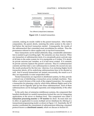
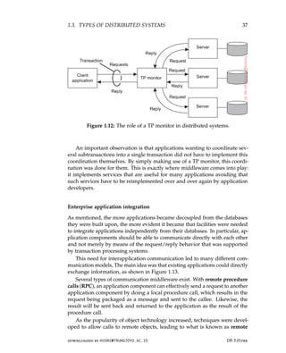
![38 CHAPTER 1. INTRODUCTION
Figure 1.13: Middleware as a communication facilitator in enterprise applica-
tion integration.
method invocations (RMI). An RMI is essentially the same as an RPC, except
that it operates on objects instead of functions.
RPC and RMI have the disadvantage that the caller and callee both need
to be up and running at the time of communication. In addition, they need
to know exactly how to refer to each other. This tight coupling is often expe-
rienced as a serious drawback, and has lead to what is known as message-
oriented middleware, or simply MOM. In this case, applications send mes-
sages to logical contact points, often described by means of a subject. Likewise,
applications can indicate their interest for a specific type of message, after
which the communication middleware will take care that those messages are
delivered to those applications. These so-called publish/subscribe systems
form an important and expanding class of distributed systems.
Note 1.10 (More information: On integrating applications)
Supporting enterprise application integration is an important goal for many mid-
dleware products. In general, there are four ways to integrate applications [Hohpe
and Woolf, 2004]:
File transfer: The essence of integration through file transfer, is that an appli-
cation produces a file containing shared data that is subsequently read
by other applications. The approach is technically very simple, making it
appealing. The drawback, however, is that there are a lot of things that
need to be agreed upon:
• File format and layout: text, binary, its structure, and so on. Nowadays,
XML has become popular as its files are, in principle, self-describing.
• File management: where are they stored, how are they named, who is
responsible for deleting files?
DS 3.01pre downloaded by HUSNI@TRUNOJOYO.AC.ID
38 CHAPTER 1. INTRODUCTION
Figure 1.13: Middleware as a communication facilitator in enterprise applica-
tion integration.
method invocations (RMI). An RMI is essentially the same as an RPC, except
that it operates on objects instead of functions.
RPC and RMI have the disadvantage that the caller and callee both need
to be up and running at the time of communication. In addition, they need
to know exactly how to refer to each other. This tight coupling is often expe-
rienced as a serious drawback, and has lead to what is known as message-
oriented middleware, or simply MOM. In this case, applications send mes-
sages to logical contact points, often described by means of a subject. Likewise,
applications can indicate their interest for a specific type of message, after
which the communication middleware will take care that those messages are
delivered to those applications. These so-called publish/subscribe systems
form an important and expanding class of distributed systems.
Note 1.10 (More information: On integrating applications)
Supporting enterprise application integration is an important goal for many mid-
dleware products. In general, there are four ways to integrate applications [Hohpe
and Woolf, 2004]:
File transfer: The essence of integration through file transfer, is that an appli-
cation produces a file containing shared data that is subsequently read
by other applications. The approach is technically very simple, making it
appealing. The drawback, however, is that there are a lot of things that
need to be agreed upon:
• File format and layout: text, binary, its structure, and so on. Nowadays,
XML has become popular as its files are, in principle, self-describing.
• File management: where are they stored, how are they named, who is
responsible for deleting files?
DS 3.01pre downloaded by HUSNI@TRUNOJOYO.AC.ID](https://image.slidesharecdn.com/distributed-systems-3rd-edition-251215232331-7e034da0/85/architectureec-distributed-systems-3rd-Edition-pdf-52-320.jpg)
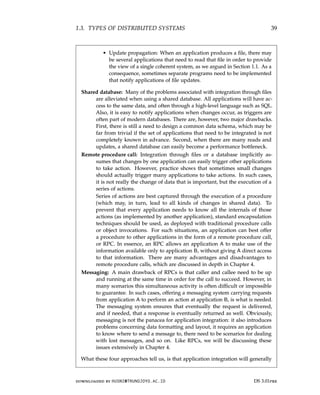
![40 CHAPTER 1. INTRODUCTION
not be simple. Middleware (in the form of a distributed system), however, can
significantly help in integration by providing the right facilities such as support
for RPCs or messaging. As said, enterprise application integration is an important
target field for many middleware products.
Pervasive systems
The distributed systems discussed so far are largely characterized by their
stability: nodes are fixed and have a more or less permanent and high-quality
connection to a network. To a certain extent, this stability is realized through
the various techniques for achieving distribution transparency. For example,
there are many ways how we can create the illusion that only occasionally
components may fail. Likewise, there are all kinds of means to hide the actual
network location of a node, effectively allowing users and applications to
believe that nodes stay put.
However, matters have changed since the introduction of mobile and
embedded computing devices, leading to what are generally referred to as
pervasive systems. As its name suggests, pervasive systems are intended to
naturally blend into our environment. They are naturally also distributed
systems, and certainly meet the characterization we gave in Section 1.1.
What makes them unique in comparison to the computing and information
systems described so far, is that the separation between users and system
components is much more blurred. There is often no single dedicated interface,
such as a screen/keyboard combination. Instead, a pervasive system is often
equipped with many sensors that pick up various aspects of a user’s behavior.
Likewise, it may have a myriad of actuators to provide information and
feedback, often even purposefully aiming to steer behavior.
Many devices in pervasive systems are characterized by being small,
battery-powered, mobile, and having only a wireless connection, although
not all these characteristics apply to all devices. These are not necessarily
restrictive characteristics, as is illustrated by smartphones [Roussos et al., 2005]
and their role in what is now coined as the Internet of Things [Mattern and
Floerkemeier, 2010; Stankovic, 2014]. Nevertheless, notably the fact that we
often need to deal with the intricacies of wireless and mobile communication,
will require special solutions to make a pervasive system as transparent or
unobtrusive as possible.
In the following, we make a distinction between three different types of
pervasive systems, although there is considerable overlap between the three
types: ubiquitous computing systems, mobile systems, and sensor networks.
This distinction allows us to focus on different aspects of pervasive systems.
DS 3.01pre downloaded by HUSNI@TRUNOJOYO.AC.ID
40 CHAPTER 1. INTRODUCTION
not be simple. Middleware (in the form of a distributed system), however, can
significantly help in integration by providing the right facilities such as support
for RPCs or messaging. As said, enterprise application integration is an important
target field for many middleware products.
Pervasive systems
The distributed systems discussed so far are largely characterized by their
stability: nodes are fixed and have a more or less permanent and high-quality
connection to a network. To a certain extent, this stability is realized through
the various techniques for achieving distribution transparency. For example,
there are many ways how we can create the illusion that only occasionally
components may fail. Likewise, there are all kinds of means to hide the actual
network location of a node, effectively allowing users and applications to
believe that nodes stay put.
However, matters have changed since the introduction of mobile and
embedded computing devices, leading to what are generally referred to as
pervasive systems. As its name suggests, pervasive systems are intended to
naturally blend into our environment. They are naturally also distributed
systems, and certainly meet the characterization we gave in Section 1.1.
What makes them unique in comparison to the computing and information
systems described so far, is that the separation between users and system
components is much more blurred. There is often no single dedicated interface,
such as a screen/keyboard combination. Instead, a pervasive system is often
equipped with many sensors that pick up various aspects of a user’s behavior.
Likewise, it may have a myriad of actuators to provide information and
feedback, often even purposefully aiming to steer behavior.
Many devices in pervasive systems are characterized by being small,
battery-powered, mobile, and having only a wireless connection, although
not all these characteristics apply to all devices. These are not necessarily
restrictive characteristics, as is illustrated by smartphones [Roussos et al., 2005]
and their role in what is now coined as the Internet of Things [Mattern and
Floerkemeier, 2010; Stankovic, 2014]. Nevertheless, notably the fact that we
often need to deal with the intricacies of wireless and mobile communication,
will require special solutions to make a pervasive system as transparent or
unobtrusive as possible.
In the following, we make a distinction between three different types of
pervasive systems, although there is considerable overlap between the three
types: ubiquitous computing systems, mobile systems, and sensor networks.
This distinction allows us to focus on different aspects of pervasive systems.
DS 3.01pre downloaded by HUSNI@TRUNOJOYO.AC.ID](https://image.slidesharecdn.com/distributed-systems-3rd-edition-251215232331-7e034da0/85/architectureec-distributed-systems-3rd-Edition-pdf-54-320.jpg)
![1.3. TYPES OF DISTRIBUTED SYSTEMS 41
Ubiquitous computing systems
So far, we have been talking about pervasive systems to emphasize that
its elements have spread through in many parts of our environment. In a
ubiquitous computing system we go one step further: the system is pervasive
and continuously present. The latter means that a user will be continuously
interacting with the system, often not even being aware that interaction is
taking place. Poslad [2009] describes the core requirements for a ubiquitous
computing system roughly as follows:
1. (Distribution) Devices are networked, distributed, and accessible in a
transparent manner
2. (Interaction) Interaction between users and devices is highly unobtru-
sive
3. (Context awareness) The system is aware of a user’s context in order to
optimize interaction
4. (Autonomy) Devices operate autonomously without human interven-
tion, and are thus highly self-managed
5. (Intelligence) The system as a whole can handle a wide range of dy-
namic actions and interactions
Let us briefly consider these requirements from a distributed-systems perspec-
tive.
Ad. 1: Distribution. As mentioned, a ubiquitous computing system is an
example of a distributed system: the devices and other computers forming
the nodes of a system are simply networked and work together to form
the illusion of a single coherent system. Distribution also comes naturally:
there will be devices close to users (such as sensors and actuators), connected
to computers hidden from view and perhaps even operating remotely in a
cloud. Most, if not all, of the requirements regarding distribution transparency
mentioned in Section 1.2, should therefore hold.
Ad. 2: Interaction. When it comes to interaction with users, ubiquitous
computing systems differ a lot in comparison to the systems we have been
discussing so far. End users play a prominent role in the design of ubiquitous
systems, meaning that special attention needs to be paid to how the interac-
tion between users and core system takes place. For ubiquitous computing
systems, much of the interaction by humans will be implicit, with an implicit
action being defined as one “that is not primarily aimed to interact with a com-
puterized system but which such a system understands as input” [Schmidt,
2000]. In other words, a user could be mostly unaware of the fact that input is
being provided to a computer system. From a certain perspective, ubiquitous
computing can be said to seemingly hide interfaces.
downloaded by HUSNI@TRUNOJOYO.AC.ID DS 3.01pre
1.3. TYPES OF DISTRIBUTED SYSTEMS 41
Ubiquitous computing systems
So far, we have been talking about pervasive systems to emphasize that
its elements have spread through in many parts of our environment. In a
ubiquitous computing system we go one step further: the system is pervasive
and continuously present. The latter means that a user will be continuously
interacting with the system, often not even being aware that interaction is
taking place. Poslad [2009] describes the core requirements for a ubiquitous
computing system roughly as follows:
1. (Distribution) Devices are networked, distributed, and accessible in a
transparent manner
2. (Interaction) Interaction between users and devices is highly unobtru-
sive
3. (Context awareness) The system is aware of a user’s context in order to
optimize interaction
4. (Autonomy) Devices operate autonomously without human interven-
tion, and are thus highly self-managed
5. (Intelligence) The system as a whole can handle a wide range of dy-
namic actions and interactions
Let us briefly consider these requirements from a distributed-systems perspec-
tive.
Ad. 1: Distribution. As mentioned, a ubiquitous computing system is an
example of a distributed system: the devices and other computers forming
the nodes of a system are simply networked and work together to form
the illusion of a single coherent system. Distribution also comes naturally:
there will be devices close to users (such as sensors and actuators), connected
to computers hidden from view and perhaps even operating remotely in a
cloud. Most, if not all, of the requirements regarding distribution transparency
mentioned in Section 1.2, should therefore hold.
Ad. 2: Interaction. When it comes to interaction with users, ubiquitous
computing systems differ a lot in comparison to the systems we have been
discussing so far. End users play a prominent role in the design of ubiquitous
systems, meaning that special attention needs to be paid to how the interac-
tion between users and core system takes place. For ubiquitous computing
systems, much of the interaction by humans will be implicit, with an implicit
action being defined as one “that is not primarily aimed to interact with a com-
puterized system but which such a system understands as input” [Schmidt,
2000]. In other words, a user could be mostly unaware of the fact that input is
being provided to a computer system. From a certain perspective, ubiquitous
computing can be said to seemingly hide interfaces.
downloaded by HUSNI@TRUNOJOYO.AC.ID DS 3.01pre](https://image.slidesharecdn.com/distributed-systems-3rd-edition-251215232331-7e034da0/85/architectureec-distributed-systems-3rd-Edition-pdf-55-320.jpg)
![42 CHAPTER 1. INTRODUCTION
A simple example is where the settings of a car’s driver’s seat, steering
wheel, and mirrors is fully personalized. If Bob takes a seat, the system will
recognize that it is dealing with Bob and subsequently makes the appropriate
adjustments. The same happens when Alice uses the car, while an unknown
user will be steered toward making his or her own adjustments (to be remem-
bered for later). This example already illustrates an important role of sensors
in ubiquitous computing, namely as input devices that are used to identify a
situation (a specific person apparently wanting to drive), whose input analysis
leads to actions (making adjustments). In turn, the actions may lead to natural
reactions, for example that Bob slightly changes the seat settings. The system
will have to take all (implicit and explicit) actions by the user into account
and react accordingly.
Ad. 3: Context awareness. Reacting to the sensory input, but also the explicit
input from users is more easily said than done. What a ubiquitous computing
system needs to do, is to take the context in which interactions take place
into account. Context awareness also differentiates ubiquitous computing
systems from the more traditional systems we have been discussing before,
and is described by Dey and Abowd [2000] as “any information that can be
used to characterize the situation of entities (i.e., whether a person, place or
object) that are considered relevant to the interaction between a user and an
application, including the user and the application themselves.” In practice,
context is often characterized by location, identity, time, and activity: the where,
who, when, and what. A system will need to have the necessary (sensory) input
to determine one or several of these context types.
What is important from a distributed-systems perspective, is that raw data
as collected by various sensors is lifted to a level of abstraction that can be
used by applications. A concrete example is detecting where a person is,
for example in terms of GPS coordinates, and subsequently mapping that
information to an actual location, such as the corner of a street, or a specific
shop or other known facility. The question is where this processing of sensory
input takes place: is all data collected at a central server connected to a
database with detailed information on a city, or is it the user’s smartphone
where the mapping is done? Clearly, there are trade-offs to be considered.
Dey [2010] discusses more general approaches toward building context-
aware applications. When it comes to combining flexibility and potential
distribution, so-called shared data spaces in which processes are decoupled
in time and space are attractive, yet as we shall see in later chapters, suffer
from scalability problems. A survey on context-awareness and its relation to
middleware and distributed systems is provided by Baldauf et al. [2007].
Ad. 4: Autonomy. An important aspect of most ubiquitous computing sys-
tems is that explicit systems management has been reduced to a minimum. In
DS 3.01pre downloaded by HUSNI@TRUNOJOYO.AC.ID
42 CHAPTER 1. INTRODUCTION
A simple example is where the settings of a car’s driver’s seat, steering
wheel, and mirrors is fully personalized. If Bob takes a seat, the system will
recognize that it is dealing with Bob and subsequently makes the appropriate
adjustments. The same happens when Alice uses the car, while an unknown
user will be steered toward making his or her own adjustments (to be remem-
bered for later). This example already illustrates an important role of sensors
in ubiquitous computing, namely as input devices that are used to identify a
situation (a specific person apparently wanting to drive), whose input analysis
leads to actions (making adjustments). In turn, the actions may lead to natural
reactions, for example that Bob slightly changes the seat settings. The system
will have to take all (implicit and explicit) actions by the user into account
and react accordingly.
Ad. 3: Context awareness. Reacting to the sensory input, but also the explicit
input from users is more easily said than done. What a ubiquitous computing
system needs to do, is to take the context in which interactions take place
into account. Context awareness also differentiates ubiquitous computing
systems from the more traditional systems we have been discussing before,
and is described by Dey and Abowd [2000] as “any information that can be
used to characterize the situation of entities (i.e., whether a person, place or
object) that are considered relevant to the interaction between a user and an
application, including the user and the application themselves.” In practice,
context is often characterized by location, identity, time, and activity: the where,
who, when, and what. A system will need to have the necessary (sensory) input
to determine one or several of these context types.
What is important from a distributed-systems perspective, is that raw data
as collected by various sensors is lifted to a level of abstraction that can be
used by applications. A concrete example is detecting where a person is,
for example in terms of GPS coordinates, and subsequently mapping that
information to an actual location, such as the corner of a street, or a specific
shop or other known facility. The question is where this processing of sensory
input takes place: is all data collected at a central server connected to a
database with detailed information on a city, or is it the user’s smartphone
where the mapping is done? Clearly, there are trade-offs to be considered.
Dey [2010] discusses more general approaches toward building context-
aware applications. When it comes to combining flexibility and potential
distribution, so-called shared data spaces in which processes are decoupled
in time and space are attractive, yet as we shall see in later chapters, suffer
from scalability problems. A survey on context-awareness and its relation to
middleware and distributed systems is provided by Baldauf et al. [2007].
Ad. 4: Autonomy. An important aspect of most ubiquitous computing sys-
tems is that explicit systems management has been reduced to a minimum. In
DS 3.01pre downloaded by HUSNI@TRUNOJOYO.AC.ID](https://image.slidesharecdn.com/distributed-systems-3rd-edition-251215232331-7e034da0/85/architectureec-distributed-systems-3rd-Edition-pdf-56-320.jpg)
![1.3. TYPES OF DISTRIBUTED SYSTEMS 43
a ubiquitous computing environment there is simply no room for a systems
administrator to keep everything up and running. As a consequence, the
system as a whole should be able to act autonomously, and automatically
react to changes. This requires a myriad of techniques of which several will
be discussed throughout this book. To give a few simple examples, think of
the following:
Address allocation: In order for networked devices to communicate, they
need an IP address. Addresses can be allocated automatically using
protocols like the Dynamic Host Configuration Protocol (DHCP) [Droms,
1997] (which requires a server) or Zeroconf [Guttman, 2001].
Adding devices: It should be easy to add devices to an existing system. A
step towards automatic configuration is realized by the Universal Plug
and Play Protocol (UPnP) [UPnP Forum, 2008]. Using UPnP, devices can
discover each other and make sure that they can set up communication
channels between them.
Automatic updates: Many devices in a ubiquitous computing system should
be able to regularly check through the Internet if their software should
be updated. If so, they can download new versions of their components
and ideally continue where they left off.
Admittedly, these are very simple examples, but the picture should be clear
that manual intervention is to be kept to a minimum. We will be discussing
many techniques related to self-management in detail throughout the book.
Ad. 5: Intelligence. Finally, Poslad [2009] mentions that ubiquitous com-
puting systems often use methods and techniques from the field of artificial
intelligence. What this means, is that in many cases a wide range of ad-
vanced algorithms and models need to be deployed to handle incomplete
input, quickly react to a changing environment, handle unexpected events,
and so on. The extent to which this can or should be done in a distributed
fashion is crucial from the perspective of distributed systems. Unfortunately,
distributed solutions for many problems in the field of artificial intelligence
are yet to be found, meaning that there may be a natural tension between
the first requirement of networked and distributed devices, and advanced
distributed information processing.
Mobile computing systems
As mentioned, mobility often forms an important component of pervasive
systems, and many, if not all aspects that we have just discussed also apply to
mobile computing. There are several issues that set mobile computing aside
downloaded by HUSNI@TRUNOJOYO.AC.ID DS 3.01pre
1.3. TYPES OF DISTRIBUTED SYSTEMS 43
a ubiquitous computing environment there is simply no room for a systems
administrator to keep everything up and running. As a consequence, the
system as a whole should be able to act autonomously, and automatically
react to changes. This requires a myriad of techniques of which several will
be discussed throughout this book. To give a few simple examples, think of
the following:
Address allocation: In order for networked devices to communicate, they
need an IP address. Addresses can be allocated automatically using
protocols like the Dynamic Host Configuration Protocol (DHCP) [Droms,
1997] (which requires a server) or Zeroconf [Guttman, 2001].
Adding devices: It should be easy to add devices to an existing system. A
step towards automatic configuration is realized by the Universal Plug
and Play Protocol (UPnP) [UPnP Forum, 2008]. Using UPnP, devices can
discover each other and make sure that they can set up communication
channels between them.
Automatic updates: Many devices in a ubiquitous computing system should
be able to regularly check through the Internet if their software should
be updated. If so, they can download new versions of their components
and ideally continue where they left off.
Admittedly, these are very simple examples, but the picture should be clear
that manual intervention is to be kept to a minimum. We will be discussing
many techniques related to self-management in detail throughout the book.
Ad. 5: Intelligence. Finally, Poslad [2009] mentions that ubiquitous com-
puting systems often use methods and techniques from the field of artificial
intelligence. What this means, is that in many cases a wide range of ad-
vanced algorithms and models need to be deployed to handle incomplete
input, quickly react to a changing environment, handle unexpected events,
and so on. The extent to which this can or should be done in a distributed
fashion is crucial from the perspective of distributed systems. Unfortunately,
distributed solutions for many problems in the field of artificial intelligence
are yet to be found, meaning that there may be a natural tension between
the first requirement of networked and distributed devices, and advanced
distributed information processing.
Mobile computing systems
As mentioned, mobility often forms an important component of pervasive
systems, and many, if not all aspects that we have just discussed also apply to
mobile computing. There are several issues that set mobile computing aside
downloaded by HUSNI@TRUNOJOYO.AC.ID DS 3.01pre](https://image.slidesharecdn.com/distributed-systems-3rd-edition-251215232331-7e034da0/85/architectureec-distributed-systems-3rd-Edition-pdf-57-320.jpg)
![44 CHAPTER 1. INTRODUCTION
to pervasive systems in general (see also Adelstein et al. [2005] and Tarkoma
and Kangasharju [2009]).
First, the devices that form part of a (distributed) mobile system may
vary widely. Typically, mobile computing is now done with devices such
as smartphones and tablet computers. However, completely different types
of devices are now using the Internet Protocol (IP) to communicate, placing
mobile computing in a different perspective. Such devices include remote
controls, pagers, active badges, car equipment, various GPS-enabled devices,
and so on. A characteristic feature of all these devices is that they use wireless
communication. Mobile implies wireless so it seems (although there are
exceptions to the rules).
Second, in mobile computing the location of a device is assumed to change
over time. A changing location has its effects on many issues. For example, if
the location of a device changes regularly, so will perhaps the services that
are locally available. As a consequence, we may need to pay special attention
to dynamically discovering services, but also letting services announce their
presence. In a similar vein, we often also want to know where a device actually
is. This may mean that we need to know the actual geographical coordinates
of a device such as in tracking and tracing applications, but it may also require
that we are able to simply detect its network position (as in mobile IP [Perkins,
2010; Perkins et al., 2011].
Changing locations also has a profound effect on communication. To
illustrate, consider a (wireless) mobile ad hoc network, generally abbreviated
as a MANET. Suppose that two devices in a MANET have discovered each
other in the sense that they know each other’s network address. How do we
route messages between the two? Static routes are generally not sustainable
as nodes along the routing path can easily move out of their neighbor’s range,
invalidating the path. For large MANETs, using a priori set-up paths is not
a viable option. What we are dealing with here are so-called disruption-
tolerant networks: networks in which connectivity between two nodes can
simply not be guaranteed. Getting a message from one node to another may
then be problematic, to say the least.
The trick in such cases, is not to attempt to set up a communication path
from the source to the destination, but to rely on two principles. First, as we
will discuss in Section 4.4, using special flooding-based techniques will allow
a message to gradually spread through a part of the network, to eventually
reach the destination. Obviously, any type of flooding will impose redundant
communication, but this may be the price we have to pay. Second, in a
disruption-tolerant network, we let an intermediate node store a received
message until it encounters another node to which it can pass it on. In other
words, a node becomes a temporary carrier of a message, as sketched in
Figure 1.14. Eventually, the message should reach its destination.
It is not difficult to imagine that selectively passing messages to encoun-
DS 3.01pre downloaded by HUSNI@TRUNOJOYO.AC.ID
44 CHAPTER 1. INTRODUCTION
to pervasive systems in general (see also Adelstein et al. [2005] and Tarkoma
and Kangasharju [2009]).
First, the devices that form part of a (distributed) mobile system may
vary widely. Typically, mobile computing is now done with devices such
as smartphones and tablet computers. However, completely different types
of devices are now using the Internet Protocol (IP) to communicate, placing
mobile computing in a different perspective. Such devices include remote
controls, pagers, active badges, car equipment, various GPS-enabled devices,
and so on. A characteristic feature of all these devices is that they use wireless
communication. Mobile implies wireless so it seems (although there are
exceptions to the rules).
Second, in mobile computing the location of a device is assumed to change
over time. A changing location has its effects on many issues. For example, if
the location of a device changes regularly, so will perhaps the services that
are locally available. As a consequence, we may need to pay special attention
to dynamically discovering services, but also letting services announce their
presence. In a similar vein, we often also want to know where a device actually
is. This may mean that we need to know the actual geographical coordinates
of a device such as in tracking and tracing applications, but it may also require
that we are able to simply detect its network position (as in mobile IP [Perkins,
2010; Perkins et al., 2011].
Changing locations also has a profound effect on communication. To
illustrate, consider a (wireless) mobile ad hoc network, generally abbreviated
as a MANET. Suppose that two devices in a MANET have discovered each
other in the sense that they know each other’s network address. How do we
route messages between the two? Static routes are generally not sustainable
as nodes along the routing path can easily move out of their neighbor’s range,
invalidating the path. For large MANETs, using a priori set-up paths is not
a viable option. What we are dealing with here are so-called disruption-
tolerant networks: networks in which connectivity between two nodes can
simply not be guaranteed. Getting a message from one node to another may
then be problematic, to say the least.
The trick in such cases, is not to attempt to set up a communication path
from the source to the destination, but to rely on two principles. First, as we
will discuss in Section 4.4, using special flooding-based techniques will allow
a message to gradually spread through a part of the network, to eventually
reach the destination. Obviously, any type of flooding will impose redundant
communication, but this may be the price we have to pay. Second, in a
disruption-tolerant network, we let an intermediate node store a received
message until it encounters another node to which it can pass it on. In other
words, a node becomes a temporary carrier of a message, as sketched in
Figure 1.14. Eventually, the message should reach its destination.
It is not difficult to imagine that selectively passing messages to encoun-
DS 3.01pre downloaded by HUSNI@TRUNOJOYO.AC.ID](https://image.slidesharecdn.com/distributed-systems-3rd-edition-251215232331-7e034da0/85/architectureec-distributed-systems-3rd-Edition-pdf-58-320.jpg)
![1.3. TYPES OF DISTRIBUTED SYSTEMS 45
Figure 1.14: Passing messages in a (mobile) disruption-tolerant network.
tered nodes may help to ensure efficient delivery. For example, if nodes are
known to belong to a certain class, and the source and destination belong to
the same class, we may decide to pass messages only among nodes in that
class. Likewise, it may prove efficient to pass messages only to well-connected
nodes, that is, nodes who have been in range of many other nodes in the
recent past. An overview is provided by Spyropoulos et al. [2010].
Note 1.11 (Advanced: Social networks and mobility patterns)
Not surprisingly, mobile computing is tightly coupled to the whereabouts of
human beings. With the increasing interest in complex social networks [Vega-
Redondo, 2007; Jackson, 2008] and the explosion of the use of smartphones,
several groups are seeking to combine analysis of social behavior and information
dissemination in so-called pocket-switched networks [Hui et al., 2005]. The latter
are networks in which nodes are formed by people (or actually, their mobile
devices), and links are formed when two people encounter each other, allowing
their devices to exchange data.
The basic idea is to let information be spread using the ad hoc communications
between people. In doing so, it becomes important to understand the structure of
a social group. One of the first to examine how social awareness can be exploited
in mobile networks were Miklas et al. [2007]. In their approach, based on traces
on encounters between people, two people are characterized as either friends or
strangers. Friends interact frequently, where the number of recurring encounters
between strangers is low. The goal is to make sure that a message from Alice to
Bob is eventually delivered.
As it turns out, when Alice adopts a strategy by which she hands out the
message to each of her friends, and that each of those friends passes the message
to Bob as soon as he is encountered, can ensure that the message reaches Bob
with a delay exceeding approximately 10% of the best-attainable delay. Any other
strategy, like forwarding the message to only 1 or 2 friends, performs much worse.
Passing a message to a stranger has no significant effect. In other words, it makes
a huge difference if nodes take friend relationships into account, but even then it
is still necessary to judiciously adopt a forwarding strategy.
downloaded by HUSNI@TRUNOJOYO.AC.ID DS 3.01pre
1.3. TYPES OF DISTRIBUTED SYSTEMS 45
Figure 1.14: Passing messages in a (mobile) disruption-tolerant network.
tered nodes may help to ensure efficient delivery. For example, if nodes are
known to belong to a certain class, and the source and destination belong to
the same class, we may decide to pass messages only among nodes in that
class. Likewise, it may prove efficient to pass messages only to well-connected
nodes, that is, nodes who have been in range of many other nodes in the
recent past. An overview is provided by Spyropoulos et al. [2010].
Note 1.11 (Advanced: Social networks and mobility patterns)
Not surprisingly, mobile computing is tightly coupled to the whereabouts of
human beings. With the increasing interest in complex social networks [Vega-
Redondo, 2007; Jackson, 2008] and the explosion of the use of smartphones,
several groups are seeking to combine analysis of social behavior and information
dissemination in so-called pocket-switched networks [Hui et al., 2005]. The latter
are networks in which nodes are formed by people (or actually, their mobile
devices), and links are formed when two people encounter each other, allowing
their devices to exchange data.
The basic idea is to let information be spread using the ad hoc communications
between people. In doing so, it becomes important to understand the structure of
a social group. One of the first to examine how social awareness can be exploited
in mobile networks were Miklas et al. [2007]. In their approach, based on traces
on encounters between people, two people are characterized as either friends or
strangers. Friends interact frequently, where the number of recurring encounters
between strangers is low. The goal is to make sure that a message from Alice to
Bob is eventually delivered.
As it turns out, when Alice adopts a strategy by which she hands out the
message to each of her friends, and that each of those friends passes the message
to Bob as soon as he is encountered, can ensure that the message reaches Bob
with a delay exceeding approximately 10% of the best-attainable delay. Any other
strategy, like forwarding the message to only 1 or 2 friends, performs much worse.
Passing a message to a stranger has no significant effect. In other words, it makes
a huge difference if nodes take friend relationships into account, but even then it
is still necessary to judiciously adopt a forwarding strategy.
downloaded by HUSNI@TRUNOJOYO.AC.ID DS 3.01pre](https://image.slidesharecdn.com/distributed-systems-3rd-edition-251215232331-7e034da0/85/architectureec-distributed-systems-3rd-Edition-pdf-59-320.jpg)
![46 CHAPTER 1. INTRODUCTION
For large groups of people, more sophisticated approaches are needed. In
the first place, it may happen that messages need to be sent between people in
different communities. What do we mean by a community? If we consider a
social network (where a vertex represents a person, and a link the fact that two
people have a social relation), then a community is roughly speaking a group of
vertices in which there are many links between its members and only few links
with vertices in other groups [Newman, 2010]. Unfortunately, many community-
detection algorithms require complete information on the social structure, making
them practically infeasible for optimizing communication in mobile networks.
Hui et al. [2007] propose a number of decentralized community detection
algorithms. In essence, these algorithms rely on letting a node i (1) detect the set
of nodes it regularly encounters, called its familiar set Fi, and (2) incrementally
expand its local community Ci, with Fi ⊆ Ci. Initially, Ci as well as Fi will be
empty, but gradually, Fi will grow, and with it, Ci. In the simplest case, a node j is
added to a community Ci as follows:
Node i adds j to Ci when
|Fj ∩ Ci|
|Fj|
λ for some λ 0
In other words, when the fraction of j’s familiar set substantially overlaps with
the community of i, then node i should add j to its community. Also, we have the
following for merging communities:
Merge two communities when |Ci ∩ Cj| γ|Ci ∪ Cj| for some γ 0
which means that two communities should be merged when they have a significant
number of members in common. (In their experiments, Hui et al. found that
setting λ = γ = 0.6 lead to good results.)
Knowing communities, in combination with the connectivity of a node in
either a community, or globally, can subsequently be used to efficiently forward
messages in a disruption-tolerant network, as explained by Hui et al. [2011].
Obviously, much of the performance of a mobile computing system depends
on how nodes move. In particular, in order to pre-assess the effectiveness of new
protocols or algorithms, having an idea on which mobility patterns are actually
realistic is important. For long, there was not much data on such patterns, but
recent experiments have changed that.
Various groups have started to collect statistics on human mobility, of which
the traces are used to drive simulations. In addition, traces have been used to
derive more realistic mobility models (see, e.g., Kim et al. [2006b]). However,
understanding human mobility patterns in general remains a difficult problem.
González et al. [2008] report on modeling efforts based on data collected from
100,000 cell-phone users during a six-month period. They observed that the
displacement behavior could be represented by the following, relatively simple
distribution:
P[∆r] = (∆r + ∆r0)−β
· e−∆r/κ
in which ∆r is the actual displacement and ∆r0 = 1.5km a constant initial dis-
placement. With β = 1.75 and κ = 400, this leads to the distribution shown in
Figure 1.15.
DS 3.01pre downloaded by HUSNI@TRUNOJOYO.AC.ID
46 CHAPTER 1. INTRODUCTION
For large groups of people, more sophisticated approaches are needed. In
the first place, it may happen that messages need to be sent between people in
different communities. What do we mean by a community? If we consider a
social network (where a vertex represents a person, and a link the fact that two
people have a social relation), then a community is roughly speaking a group of
vertices in which there are many links between its members and only few links
with vertices in other groups [Newman, 2010]. Unfortunately, many community-
detection algorithms require complete information on the social structure, making
them practically infeasible for optimizing communication in mobile networks.
Hui et al. [2007] propose a number of decentralized community detection
algorithms. In essence, these algorithms rely on letting a node i (1) detect the set
of nodes it regularly encounters, called its familiar set Fi, and (2) incrementally
expand its local community Ci, with Fi ⊆ Ci. Initially, Ci as well as Fi will be
empty, but gradually, Fi will grow, and with it, Ci. In the simplest case, a node j is
added to a community Ci as follows:
Node i adds j to Ci when
|Fj ∩ Ci|
|Fj|
λ for some λ 0
In other words, when the fraction of j’s familiar set substantially overlaps with
the community of i, then node i should add j to its community. Also, we have the
following for merging communities:
Merge two communities when |Ci ∩ Cj| γ|Ci ∪ Cj| for some γ 0
which means that two communities should be merged when they have a significant
number of members in common. (In their experiments, Hui et al. found that
setting λ = γ = 0.6 lead to good results.)
Knowing communities, in combination with the connectivity of a node in
either a community, or globally, can subsequently be used to efficiently forward
messages in a disruption-tolerant network, as explained by Hui et al. [2011].
Obviously, much of the performance of a mobile computing system depends
on how nodes move. In particular, in order to pre-assess the effectiveness of new
protocols or algorithms, having an idea on which mobility patterns are actually
realistic is important. For long, there was not much data on such patterns, but
recent experiments have changed that.
Various groups have started to collect statistics on human mobility, of which
the traces are used to drive simulations. In addition, traces have been used to
derive more realistic mobility models (see, e.g., Kim et al. [2006b]). However,
understanding human mobility patterns in general remains a difficult problem.
González et al. [2008] report on modeling efforts based on data collected from
100,000 cell-phone users during a six-month period. They observed that the
displacement behavior could be represented by the following, relatively simple
distribution:
P[∆r] = (∆r + ∆r0)−β
· e−∆r/κ
in which ∆r is the actual displacement and ∆r0 = 1.5km a constant initial dis-
placement. With β = 1.75 and κ = 400, this leads to the distribution shown in
Figure 1.15.
DS 3.01pre downloaded by HUSNI@TRUNOJOYO.AC.ID](https://image.slidesharecdn.com/distributed-systems-3rd-edition-251215232331-7e034da0/85/architectureec-distributed-systems-3rd-Edition-pdf-60-320.jpg)
![1.3. TYPES OF DISTRIBUTED SYSTEMS 47
Figure 1.15: The distribution of displacement of (mobile) cell-phone users.
We can conclude that people tend to stay put. In fact, further analysis revealed
that people tend to return to the same place after 24, 48, or 72 hours, clearly
showing that people tend to go the same places. In a follow-up study, Song
et al. [2010] could indeed show that human mobility is actually remarkably well
predictable.
Sensor networks
Our last example of pervasive systems is sensor networks. These networks in
many cases form part of the enabling technology for pervasiveness and we
see that many solutions for sensor networks return in pervasive applications.
What makes sensor networks interesting from a distributed system’s perspec-
tive is that they are more than just a collection of input devices. Instead, as
we shall see, sensor nodes often collaborate to efficiently process the sensed
data in an application-specific manner, making them very different from, for
example, traditional computer networks. Akyildiz et al. [2002] and Akyildiz
et al. [2005] provide an overview from a networking perspective. A more
systems-oriented introduction to sensor networks is given by Zhao and Guibas
[2004], but also Karl and Willig [2005] will show to be useful.
A sensor network generally consists of tens to hundreds or thousands of
relatively small nodes, each equipped with one or more sensing devices. In
addition, nodes can often act as actuators [Akyildiz and Kasimoglu, 2004],
a typical example being the automatic activation of sprinklers when a fire
has been detected. Many sensor networks use wireless communication, and
the nodes are often battery powered. Their limited resources, restricted
communication capabilities, and constrained power consumption demand
that efficiency is high on the list of design criteria.
When zooming into an individual node, we see that, conceptually, they
do not differ a lot from “normal” computers: above the hardware there is a
software layer akin to what traditional operating systems offer, including low-
downloaded by HUSNI@TRUNOJOYO.AC.ID DS 3.01pre
1.3. TYPES OF DISTRIBUTED SYSTEMS 47
Figure 1.15: The distribution of displacement of (mobile) cell-phone users.
We can conclude that people tend to stay put. In fact, further analysis revealed
that people tend to return to the same place after 24, 48, or 72 hours, clearly
showing that people tend to go the same places. In a follow-up study, Song
et al. [2010] could indeed show that human mobility is actually remarkably well
predictable.
Sensor networks
Our last example of pervasive systems is sensor networks. These networks in
many cases form part of the enabling technology for pervasiveness and we
see that many solutions for sensor networks return in pervasive applications.
What makes sensor networks interesting from a distributed system’s perspec-
tive is that they are more than just a collection of input devices. Instead, as
we shall see, sensor nodes often collaborate to efficiently process the sensed
data in an application-specific manner, making them very different from, for
example, traditional computer networks. Akyildiz et al. [2002] and Akyildiz
et al. [2005] provide an overview from a networking perspective. A more
systems-oriented introduction to sensor networks is given by Zhao and Guibas
[2004], but also Karl and Willig [2005] will show to be useful.
A sensor network generally consists of tens to hundreds or thousands of
relatively small nodes, each equipped with one or more sensing devices. In
addition, nodes can often act as actuators [Akyildiz and Kasimoglu, 2004],
a typical example being the automatic activation of sprinklers when a fire
has been detected. Many sensor networks use wireless communication, and
the nodes are often battery powered. Their limited resources, restricted
communication capabilities, and constrained power consumption demand
that efficiency is high on the list of design criteria.
When zooming into an individual node, we see that, conceptually, they
do not differ a lot from “normal” computers: above the hardware there is a
software layer akin to what traditional operating systems offer, including low-
downloaded by HUSNI@TRUNOJOYO.AC.ID DS 3.01pre](https://image.slidesharecdn.com/distributed-systems-3rd-edition-251215232331-7e034da0/85/architectureec-distributed-systems-3rd-Edition-pdf-61-320.jpg)
![48 CHAPTER 1. INTRODUCTION
level network access, access to sensors and actuators, memory management,
and so on. Normally, support for specific services is included, such as
localization, local storage (think of additional flash devices), and convenient
communication facilities such as messaging and routing. However, similar to
other networked computer systems, additional support is needed to effectively
deploy sensor network applications. In distributed systems, this takes the form
of middleware. For sensor networks, instead of looking at middleware, it is
better to see what kind of programming support is provided, which has been
extensively surveyed by Mottola and Picco [2011].
One typical aspect in programming support is the scope provided by
communication primitives. This scope can vary between addressing the
physical neighborhood of a node, and providing primitives for systemwide
communication. In addition, it may also be possible to address a specific group
of nodes. Likewise, computations may be restricted to an individual node, a
group of nodes, or affect all nodes. To illustrate, Welsh and Mainland [2004]
use so-called abstract regions allowing a node to identify a neighborhood
from where it can, for example, gather information:
1 region = k_nearest_region.create(8);
2 reading = get_sensor_reading();
3 region.putvar(reading_key, reading);
4 max_id = region.reduce(OP_MAXID, reading_key);
In line 1, a node first creates a region of its eight nearest neighbors, after which
it fetches a value from its sensor(s). This reading is subsequently written to
the previously defined region to be defined using the key reading_key. In
line 4, the node checks whose sensor reading in the defined region was the
largest, which is returned in the variable max_id.
As another related example, consider a sensor network as implementing a
distributed database, which is, according to Mottola and Picco [2011], one of
four possible ways of accessing data. This database view is quite common and
easy to understand when realizing that many sensor networks are deployed
for measurement and surveillance applications [Bonnet et al., 2002]. In these
cases, an operator would like to extract information from (a part of) the
network by simply issuing queries such as “What is the northbound traffic
load on highway 1 as Santa Cruz?” Such queries resemble those of traditional
databases. In this case, the answer will probably need to be provided through
collaboration of many sensors along highway 1, while leaving other sensors
untouched.
To organize a sensor network as a distributed database, there are essentially
two extremes, as shown in Figure 1.16. First, sensors do not cooperate but
simply send their data to a centralized database located at the operator’s site.
The other extreme is to forward queries to relevant sensors and to let each
compute an answer, requiring the operator to aggregate the responses.
Neither of these solutions is very attractive. The first one requires that
DS 3.01pre downloaded by HUSNI@TRUNOJOYO.AC.ID
48 CHAPTER 1. INTRODUCTION
level network access, access to sensors and actuators, memory management,
and so on. Normally, support for specific services is included, such as
localization, local storage (think of additional flash devices), and convenient
communication facilities such as messaging and routing. However, similar to
other networked computer systems, additional support is needed to effectively
deploy sensor network applications. In distributed systems, this takes the form
of middleware. For sensor networks, instead of looking at middleware, it is
better to see what kind of programming support is provided, which has been
extensively surveyed by Mottola and Picco [2011].
One typical aspect in programming support is the scope provided by
communication primitives. This scope can vary between addressing the
physical neighborhood of a node, and providing primitives for systemwide
communication. In addition, it may also be possible to address a specific group
of nodes. Likewise, computations may be restricted to an individual node, a
group of nodes, or affect all nodes. To illustrate, Welsh and Mainland [2004]
use so-called abstract regions allowing a node to identify a neighborhood
from where it can, for example, gather information:
1 region = k_nearest_region.create(8);
2 reading = get_sensor_reading();
3 region.putvar(reading_key, reading);
4 max_id = region.reduce(OP_MAXID, reading_key);
In line 1, a node first creates a region of its eight nearest neighbors, after which
it fetches a value from its sensor(s). This reading is subsequently written to
the previously defined region to be defined using the key reading_key. In
line 4, the node checks whose sensor reading in the defined region was the
largest, which is returned in the variable max_id.
As another related example, consider a sensor network as implementing a
distributed database, which is, according to Mottola and Picco [2011], one of
four possible ways of accessing data. This database view is quite common and
easy to understand when realizing that many sensor networks are deployed
for measurement and surveillance applications [Bonnet et al., 2002]. In these
cases, an operator would like to extract information from (a part of) the
network by simply issuing queries such as “What is the northbound traffic
load on highway 1 as Santa Cruz?” Such queries resemble those of traditional
databases. In this case, the answer will probably need to be provided through
collaboration of many sensors along highway 1, while leaving other sensors
untouched.
To organize a sensor network as a distributed database, there are essentially
two extremes, as shown in Figure 1.16. First, sensors do not cooperate but
simply send their data to a centralized database located at the operator’s site.
The other extreme is to forward queries to relevant sensors and to let each
compute an answer, requiring the operator to aggregate the responses.
Neither of these solutions is very attractive. The first one requires that
DS 3.01pre downloaded by HUSNI@TRUNOJOYO.AC.ID](https://image.slidesharecdn.com/distributed-systems-3rd-edition-251215232331-7e034da0/85/architectureec-distributed-systems-3rd-Edition-pdf-62-320.jpg)
![1.3. TYPES OF DISTRIBUTED SYSTEMS 49
(a)
(b)
Figure 1.16: Organizing a sensor network database, while storing and pro-
cessing data (a) only at the operator’s site or (b) only at the sensors.
sensors send all their measured data through the network, which may waste
network resources and energy. The second solution may also be wasteful as
it discards the aggregation capabilities of sensors which would allow much
less data to be returned to the operator. What is needed are facilities for in-
network data processing, similar to the previous example of abstract regions.
In-network processing can be done in numerous ways. One obvious one is
to forward a query to all sensor nodes along a tree encompassing all nodes
and to subsequently aggregate the results as they are propagated back to the
root, where the initiator is located. Aggregation will take place where two
or more branches of the tree come together. As simple as this scheme may
sound, it introduces difficult questions:
• How do we (dynamically) set up an efficient tree in a sensor network?
• How does aggregation of results take place? Can it be controlled?
• What happens when network links fail?
These questions have been partly addressed in TinyDB, which implements
a declarative (database) interface to wireless sensor networks [Madden et al.,
2005]. In essence, TinyDB can use any tree-based routing algorithm. An
downloaded by HUSNI@TRUNOJOYO.AC.ID DS 3.01pre
1.3. TYPES OF DISTRIBUTED SYSTEMS 49
(a)
(b)
Figure 1.16: Organizing a sensor network database, while storing and pro-
cessing data (a) only at the operator’s site or (b) only at the sensors.
sensors send all their measured data through the network, which may waste
network resources and energy. The second solution may also be wasteful as
it discards the aggregation capabilities of sensors which would allow much
less data to be returned to the operator. What is needed are facilities for in-
network data processing, similar to the previous example of abstract regions.
In-network processing can be done in numerous ways. One obvious one is
to forward a query to all sensor nodes along a tree encompassing all nodes
and to subsequently aggregate the results as they are propagated back to the
root, where the initiator is located. Aggregation will take place where two
or more branches of the tree come together. As simple as this scheme may
sound, it introduces difficult questions:
• How do we (dynamically) set up an efficient tree in a sensor network?
• How does aggregation of results take place? Can it be controlled?
• What happens when network links fail?
These questions have been partly addressed in TinyDB, which implements
a declarative (database) interface to wireless sensor networks [Madden et al.,
2005]. In essence, TinyDB can use any tree-based routing algorithm. An
downloaded by HUSNI@TRUNOJOYO.AC.ID DS 3.01pre](https://image.slidesharecdn.com/distributed-systems-3rd-edition-251215232331-7e034da0/85/architectureec-distributed-systems-3rd-Edition-pdf-63-320.jpg)
![50 CHAPTER 1. INTRODUCTION
intermediate node will collect and aggregate the results from its children,
along with its own findings, and send that toward the root. To make matters
efficient, queries span a period of time allowing for careful scheduling of
operations so that network resources and energy are optimally consumed.
However, when queries can be initiated from different points in the net-
work, using single-rooted trees such as in TinyDB may not be efficient enough.
As an alternative, sensor networks may be equipped with special nodes where
results are forwarded to, as well as the queries related to those results. To give
a simple example, queries and results related to temperature readings may
be collected at a different location than those related to humidity measure-
ments. This approach corresponds directly to the notion of publish/subscribe
systems.
Note 1.12 (Advanced: When energy starts to become critical)
As mentioned, many sensor networks need to operate on an energy budget
coming from the use of batteries or other limited power supplies. An approach to
reduce energy consumption, is to let nodes be active only part of the time. More
specifically, assume that a node is repeatedly active during Tactive time units, and
between these active periods, it is suspended for Tsuspended units. The fraction of
time that a node is active is known as its duty cycle τ, that is,
τ =
Tactive
Tactive + Tsuspended
Values for τ are typically in the order of 10 − 30%, but when a network needs
to stay operational for periods exceeding many months, or even years, attaining
values as low as 1% are critical.
A problem with duty-cycled networks is that, in principle, nodes need to be
active at the same time for otherwise communication would simply not be possible.
Considering that while a node is suspended, only its local clock continues ticking,
and that these clocks are subject to drifts, waking up at the same time may be
problematic. This is particularly true for networks with very low duty cycles.
When a group of nodes are active at the same time, the nodes are said to
form a synchronized group. There are essentially two problems that need to be
addressed. First, we need to make sure that the nodes in a synchronized group
remain active at the same time. In practice, this turns out to be relatively simple
if each node communicates information on its current local time. Then, simple
local clock adjustments will do the trick. The second problem is more difficult,
namely how two different synchronized groups can be merged into one in which
all nodes are synchronized. Let us take a closer look at what we are facing. Most
of the following discussion is based on material by Voulgaris et al. [2016].
In order to have two groups be merged, we need to first ensure that one group
detects the other. Indeed, if their respective active periods are completely disjoint,
there is no hope that any node in one group can pick up a message from a node
in the other group. In an active detection method, a node will send a join message
during its suspended period. In other words, while it is suspended, it temporarily
DS 3.01pre downloaded by HUSNI@TRUNOJOYO.AC.ID
50 CHAPTER 1. INTRODUCTION
intermediate node will collect and aggregate the results from its children,
along with its own findings, and send that toward the root. To make matters
efficient, queries span a period of time allowing for careful scheduling of
operations so that network resources and energy are optimally consumed.
However, when queries can be initiated from different points in the net-
work, using single-rooted trees such as in TinyDB may not be efficient enough.
As an alternative, sensor networks may be equipped with special nodes where
results are forwarded to, as well as the queries related to those results. To give
a simple example, queries and results related to temperature readings may
be collected at a different location than those related to humidity measure-
ments. This approach corresponds directly to the notion of publish/subscribe
systems.
Note 1.12 (Advanced: When energy starts to become critical)
As mentioned, many sensor networks need to operate on an energy budget
coming from the use of batteries or other limited power supplies. An approach to
reduce energy consumption, is to let nodes be active only part of the time. More
specifically, assume that a node is repeatedly active during Tactive time units, and
between these active periods, it is suspended for Tsuspended units. The fraction of
time that a node is active is known as its duty cycle τ, that is,
τ =
Tactive
Tactive + Tsuspended
Values for τ are typically in the order of 10 − 30%, but when a network needs
to stay operational for periods exceeding many months, or even years, attaining
values as low as 1% are critical.
A problem with duty-cycled networks is that, in principle, nodes need to be
active at the same time for otherwise communication would simply not be possible.
Considering that while a node is suspended, only its local clock continues ticking,
and that these clocks are subject to drifts, waking up at the same time may be
problematic. This is particularly true for networks with very low duty cycles.
When a group of nodes are active at the same time, the nodes are said to
form a synchronized group. There are essentially two problems that need to be
addressed. First, we need to make sure that the nodes in a synchronized group
remain active at the same time. In practice, this turns out to be relatively simple
if each node communicates information on its current local time. Then, simple
local clock adjustments will do the trick. The second problem is more difficult,
namely how two different synchronized groups can be merged into one in which
all nodes are synchronized. Let us take a closer look at what we are facing. Most
of the following discussion is based on material by Voulgaris et al. [2016].
In order to have two groups be merged, we need to first ensure that one group
detects the other. Indeed, if their respective active periods are completely disjoint,
there is no hope that any node in one group can pick up a message from a node
in the other group. In an active detection method, a node will send a join message
during its suspended period. In other words, while it is suspended, it temporarily
DS 3.01pre downloaded by HUSNI@TRUNOJOYO.AC.ID](https://image.slidesharecdn.com/distributed-systems-3rd-edition-251215232331-7e034da0/85/architectureec-distributed-systems-3rd-Edition-pdf-64-320.jpg)
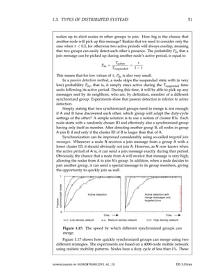
![52 CHAPTER 1. INTRODUCTION
experiments show that bringing even a large mobile, duty-cycled network to a
state in which all nodes are active at the same time is quite feasible. For further
information, see Voulgaris et al. [2016].
1.4 Summary
Distributed systems consist of autonomous computers that work together to
give the appearance of a single coherent system. This combination of inde-
pendent, yet coherent collective behavior is achieved by collecting application-
independent protocols into what is known as middleware: a software layer
logically placed between operating systems and distributed applications. Pro-
tocols include those for communication, transactions, service composition,
and perhaps most important, reliability.
Design goals for distributed systems include sharing resources and ensur-
ing openness. In addition, designers aim at hiding many of the intricacies
related to the distribution of processes, data, and control. However, this
distribution transparency not only comes at a performance price, in practical
situations it can never be fully achieved. The fact that trade-offs need to
be made between achieving various forms of distribution transparency is
inherent to the design of distributed systems, and can easily complicate their
understanding. One specific difficult design goal that does not always blend
well with achieving distribution transparency is scalability. This is particularly
true for geographical scalability, in which case hiding latencies and bandwidth
restrictions can turn out to be difficult. Likewise, administrative scalability
by which a system is designed to span multiple administrative domains, may
easily conflict goals for achieving distribution transparency.
Matters are further complicated by the fact that many developers initially
make assumptions about the underlying network that are fundamentally
wrong. Later, when assumptions are dropped, it may turn out to be difficult
to mask unwanted behavior. A typical example is assuming that network
latency is not significant. Other pitfalls include assuming that the network is
reliable, static, secure, and homogeneous.
Different types of distributed systems exist which can be classified as
being oriented toward supporting computations, information processing, and
pervasiveness. Distributed computing systems are typically deployed for
high-performance applications often originating from the field of parallel
computing. A field that emerged from parallel processing was initially grid
computing with a strong focus on worldwide sharing of resources, in turn
leading to what is now known as cloud computing. Cloud computing goes
beyond high-performance computing and also supports distributed systems
found in traditional office environments where we see databases playing an
important role. Typically, transaction processing systems are deployed in
DS 3.01pre downloaded by HUSNI@TRUNOJOYO.AC.ID
52 CHAPTER 1. INTRODUCTION
experiments show that bringing even a large mobile, duty-cycled network to a
state in which all nodes are active at the same time is quite feasible. For further
information, see Voulgaris et al. [2016].
1.4 Summary
Distributed systems consist of autonomous computers that work together to
give the appearance of a single coherent system. This combination of inde-
pendent, yet coherent collective behavior is achieved by collecting application-
independent protocols into what is known as middleware: a software layer
logically placed between operating systems and distributed applications. Pro-
tocols include those for communication, transactions, service composition,
and perhaps most important, reliability.
Design goals for distributed systems include sharing resources and ensur-
ing openness. In addition, designers aim at hiding many of the intricacies
related to the distribution of processes, data, and control. However, this
distribution transparency not only comes at a performance price, in practical
situations it can never be fully achieved. The fact that trade-offs need to
be made between achieving various forms of distribution transparency is
inherent to the design of distributed systems, and can easily complicate their
understanding. One specific difficult design goal that does not always blend
well with achieving distribution transparency is scalability. This is particularly
true for geographical scalability, in which case hiding latencies and bandwidth
restrictions can turn out to be difficult. Likewise, administrative scalability
by which a system is designed to span multiple administrative domains, may
easily conflict goals for achieving distribution transparency.
Matters are further complicated by the fact that many developers initially
make assumptions about the underlying network that are fundamentally
wrong. Later, when assumptions are dropped, it may turn out to be difficult
to mask unwanted behavior. A typical example is assuming that network
latency is not significant. Other pitfalls include assuming that the network is
reliable, static, secure, and homogeneous.
Different types of distributed systems exist which can be classified as
being oriented toward supporting computations, information processing, and
pervasiveness. Distributed computing systems are typically deployed for
high-performance applications often originating from the field of parallel
computing. A field that emerged from parallel processing was initially grid
computing with a strong focus on worldwide sharing of resources, in turn
leading to what is now known as cloud computing. Cloud computing goes
beyond high-performance computing and also supports distributed systems
found in traditional office environments where we see databases playing an
important role. Typically, transaction processing systems are deployed in
DS 3.01pre downloaded by HUSNI@TRUNOJOYO.AC.ID](https://image.slidesharecdn.com/distributed-systems-3rd-edition-251215232331-7e034da0/85/architectureec-distributed-systems-3rd-Edition-pdf-66-320.jpg)

![56 CHAPTER 2. ARCHITECTURES
often organized in a hybrid fashion, combining elements from centralized and
decentralized architectures. We discuss a few typical examples.
We end this chapter by considering the organization of two widely applied
distributed systems: the NFS file-sharing system and the Web.
2.1 Architectural styles
We start our discussion on architectures by first considering the logical organi-
zation of a distributed system into software components, also referred to as its
software architecture [Bass et al., 2003]. Research on software architectures
has matured considerably and it is now commonly accepted that designing
or adopting an architecture is crucial for the successful development of large
software systems.
For our discussion, the notion of an architectural style is important. Such
a style is formulated in terms of components, the way that components are
connected to each other, the data exchanged between components, and finally
how these elements are jointly configured into a system. A component is
a modular unit with well-defined required and provided interfaces that is
replaceable within its environment [OMG, 2004b]. That a component can be
replaced, and, in particular, while a system continues to operate, is important.
This is due to the fact that in many cases, it is not an option to shut down
a system for maintenance. At best, only parts of it may be put temporarily
out of order. Replacing a component can be done only if its interfaces remain
untouched.
A somewhat more difficult concept to grasp is that of a connector, which
is generally described as a mechanism that mediates communication, coor-
dination, or cooperation among components [Mehta et al., 2000; Shaw and
Clements, 1997]. For example, a connector can be formed by the facilities for
(remote) procedure calls, message passing, or streaming data. In other words,
a connector allows for the flow of control and data between components.
Using components and connectors, we can come to various configurations,
which, in turn, have been classified into architectural styles. Several styles
have by now been identified, of which the most important ones for distributed
systems are:
• Layered architectures
• Object-based architectures
• Resource-centered architectures
• Event-based architectures
In the following, we discuss each of these styles separately. We note in
advance that in most real-world distributed systems, many different styles are
combined. Notably following an approach by which a system is subdivided
DS 3.01pre downloaded by HUSNI@TRUNOJOYO.AC.ID
56 CHAPTER 2. ARCHITECTURES
often organized in a hybrid fashion, combining elements from centralized and
decentralized architectures. We discuss a few typical examples.
We end this chapter by considering the organization of two widely applied
distributed systems: the NFS file-sharing system and the Web.
2.1 Architectural styles
We start our discussion on architectures by first considering the logical organi-
zation of a distributed system into software components, also referred to as its
software architecture [Bass et al., 2003]. Research on software architectures
has matured considerably and it is now commonly accepted that designing
or adopting an architecture is crucial for the successful development of large
software systems.
For our discussion, the notion of an architectural style is important. Such
a style is formulated in terms of components, the way that components are
connected to each other, the data exchanged between components, and finally
how these elements are jointly configured into a system. A component is
a modular unit with well-defined required and provided interfaces that is
replaceable within its environment [OMG, 2004b]. That a component can be
replaced, and, in particular, while a system continues to operate, is important.
This is due to the fact that in many cases, it is not an option to shut down
a system for maintenance. At best, only parts of it may be put temporarily
out of order. Replacing a component can be done only if its interfaces remain
untouched.
A somewhat more difficult concept to grasp is that of a connector, which
is generally described as a mechanism that mediates communication, coor-
dination, or cooperation among components [Mehta et al., 2000; Shaw and
Clements, 1997]. For example, a connector can be formed by the facilities for
(remote) procedure calls, message passing, or streaming data. In other words,
a connector allows for the flow of control and data between components.
Using components and connectors, we can come to various configurations,
which, in turn, have been classified into architectural styles. Several styles
have by now been identified, of which the most important ones for distributed
systems are:
• Layered architectures
• Object-based architectures
• Resource-centered architectures
• Event-based architectures
In the following, we discuss each of these styles separately. We note in
advance that in most real-world distributed systems, many different styles are
combined. Notably following an approach by which a system is subdivided
DS 3.01pre downloaded by HUSNI@TRUNOJOYO.AC.ID](https://image.slidesharecdn.com/distributed-systems-3rd-edition-251215232331-7e034da0/85/architectureec-distributed-systems-3rd-Edition-pdf-70-320.jpg)
![2.1. ARCHITECTURAL STYLES 57
into several (logical) layers is such a universal principle that it is generally
combined with most other architectural styles.
Layered architectures
The basic idea for the layered style is simple: components are organized in
a layered fashion where a component at layer Lj can make a downcall to
a component at a lower-level layer Li (with i j) and generally expects a
response. Only in exceptional cases will an upcall be made to a higher-level
component. The three common cases are shown in Figure 2.1.
(a) (b) (c)
Figure 2.1: (a) Pure layered organization. (b) Mixed layered organization.
(c) Layered organization with upcalls (adopted from [Krakowiak, 2009]).
Figure 2.1(a) shows a standard organization in which only downcalls to
the next lower layer are made. This organization is commonly deployed in
the case of network communication.
In many situations we also encounter the organization shown in Fig-
ure 2.1(b). Consider, for example, an application A that makes use of a library
LOS to interface to an operating system. At the same time, the application uses
a specialized mathematical library Lmath that has been implemented by also
making use of LOS. In this case, referring to Figure 2.1(b), A is implemented at
layer N − 1, Lmath at layer N − 2, and LOS which is common to both of them,
at layer N − 3.
Finally, a special situation is shown in Figure 2.1(c). In some cases, it
is convenient to have a lower layer do an upcall to its next higher layer. A
typical example is when an operating system signals the occurrence of an
event, to which end it calls a user-defined operation for which an application
had previously passed a reference (typically referred to as a handle).
downloaded by HUSNI@TRUNOJOYO.AC.ID DS 3.01pre
2.1. ARCHITECTURAL STYLES 57
into several (logical) layers is such a universal principle that it is generally
combined with most other architectural styles.
Layered architectures
The basic idea for the layered style is simple: components are organized in
a layered fashion where a component at layer Lj can make a downcall to
a component at a lower-level layer Li (with i j) and generally expects a
response. Only in exceptional cases will an upcall be made to a higher-level
component. The three common cases are shown in Figure 2.1.
(a) (b) (c)
Figure 2.1: (a) Pure layered organization. (b) Mixed layered organization.
(c) Layered organization with upcalls (adopted from [Krakowiak, 2009]).
Figure 2.1(a) shows a standard organization in which only downcalls to
the next lower layer are made. This organization is commonly deployed in
the case of network communication.
In many situations we also encounter the organization shown in Fig-
ure 2.1(b). Consider, for example, an application A that makes use of a library
LOS to interface to an operating system. At the same time, the application uses
a specialized mathematical library Lmath that has been implemented by also
making use of LOS. In this case, referring to Figure 2.1(b), A is implemented at
layer N − 1, Lmath at layer N − 2, and LOS which is common to both of them,
at layer N − 3.
Finally, a special situation is shown in Figure 2.1(c). In some cases, it
is convenient to have a lower layer do an upcall to its next higher layer. A
typical example is when an operating system signals the occurrence of an
event, to which end it calls a user-defined operation for which an application
had previously passed a reference (typically referred to as a handle).
downloaded by HUSNI@TRUNOJOYO.AC.ID DS 3.01pre](https://image.slidesharecdn.com/distributed-systems-3rd-edition-251215232331-7e034da0/85/architectureec-distributed-systems-3rd-Edition-pdf-71-320.jpg)
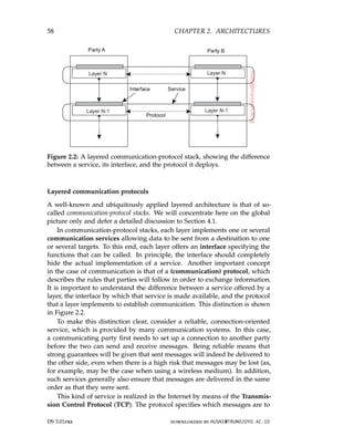
![2.1. ARCHITECTURAL STYLES 59
be exchanged for setting up or tearing down a connection, what needs to
be done to preserve the ordering of transferred data, and what both parties
need to do to detect and correct data that was lost during transmission. The
service is made available in the form of a relatively simple programming
interface, containing calls to set up a connection, send and receive messages,
and to tear down the connection again. In fact, there are different interfaces
available, often dependent on operating system or programming language
used. Likewise, there are many different implementations of the protocol and
its interfaces. (All of the gory details can be found in [Stevens, 1994; Wright
and Stevens, 1995].)
Note 2.1 (Example: Two communicating parties)
To make this distinction between service, interface, and protocol more concrete,
consider the following two communicating parties, also known as a client and a
server, respectively, expressed in Python (note that some code has been removed
for clarity).
1 from socket import *
2 s = socket(AF_INET, SOCK_STREAM)
3 (conn, addr) = s.accept() # returns new socket and addr. client
4 while True: # forever
5 data = conn.recv(1024) # receive data from client
6 if not data: break # stop if client stopped
7 conn.send(str(data)+*) # return sent data plus an *
8 conn.close() # close the connection
(a) A simple server
1 from socket import *
2 s = socket(AF_INET, SOCK_STREAM)
3 s.connect((HOST, PORT)) # connect to server (block until accepted)
4 s.send(’Hello, world’) # send some data
5 data = s.recv(1024) # receive the response
6 print data # print the result
7 s.close() # close the connection
(b) A client
Figure 2.3: Two communicating parties.
In this example, a server is created that makes use of a connection-oriented
service as offered by the socket library available in Python. This service allows
two communicating parties to reliably send and receive data over a connection.
The main functions available in its interface are:
• socket(): to create an object representing the connection
• accept(): a blocking call to wait for incoming connection requests; if
successful, the call returns a new socket for a separate connection
• connect(): to set up a connection to a specified party
• close(): to tear down a connection
• send(), recv(): to send and receive data over a connection, respectively
downloaded by HUSNI@TRUNOJOYO.AC.ID DS 3.01pre
2.1. ARCHITECTURAL STYLES 59
be exchanged for setting up or tearing down a connection, what needs to
be done to preserve the ordering of transferred data, and what both parties
need to do to detect and correct data that was lost during transmission. The
service is made available in the form of a relatively simple programming
interface, containing calls to set up a connection, send and receive messages,
and to tear down the connection again. In fact, there are different interfaces
available, often dependent on operating system or programming language
used. Likewise, there are many different implementations of the protocol and
its interfaces. (All of the gory details can be found in [Stevens, 1994; Wright
and Stevens, 1995].)
Note 2.1 (Example: Two communicating parties)
To make this distinction between service, interface, and protocol more concrete,
consider the following two communicating parties, also known as a client and a
server, respectively, expressed in Python (note that some code has been removed
for clarity).
1 from socket import *
2 s = socket(AF_INET, SOCK_STREAM)
3 (conn, addr) = s.accept() # returns new socket and addr. client
4 while True: # forever
5 data = conn.recv(1024) # receive data from client
6 if not data: break # stop if client stopped
7 conn.send(str(data)+*) # return sent data plus an *
8 conn.close() # close the connection
(a) A simple server
1 from socket import *
2 s = socket(AF_INET, SOCK_STREAM)
3 s.connect((HOST, PORT)) # connect to server (block until accepted)
4 s.send(’Hello, world’) # send some data
5 data = s.recv(1024) # receive the response
6 print data # print the result
7 s.close() # close the connection
(b) A client
Figure 2.3: Two communicating parties.
In this example, a server is created that makes use of a connection-oriented
service as offered by the socket library available in Python. This service allows
two communicating parties to reliably send and receive data over a connection.
The main functions available in its interface are:
• socket(): to create an object representing the connection
• accept(): a blocking call to wait for incoming connection requests; if
successful, the call returns a new socket for a separate connection
• connect(): to set up a connection to a specified party
• close(): to tear down a connection
• send(), recv(): to send and receive data over a connection, respectively
downloaded by HUSNI@TRUNOJOYO.AC.ID DS 3.01pre](https://image.slidesharecdn.com/distributed-systems-3rd-edition-251215232331-7e034da0/85/architectureec-distributed-systems-3rd-Edition-pdf-73-320.jpg)
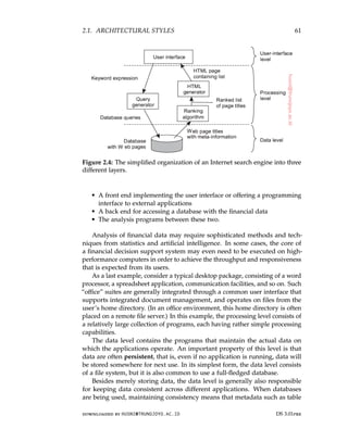
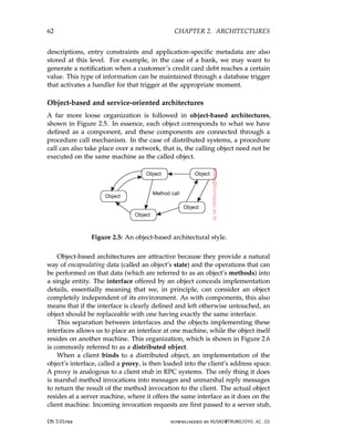
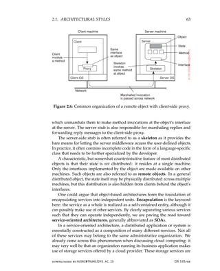
![64 CHAPTER 2. ARCHITECTURES
logically completely encapsulated into a single unit, of which an interface is
made available to customers.
Of course, storage is a rather basic service, but more sophisticated situa-
tions easily come to mind. Consider, for example, a Web shop selling goods
such as e-books. A simple implementation following the application layering
we discussed previously, may consist of an application for processing orders,
which, in turn, operates on a local database containing the e-books. Order
processing typically involves selecting items, registering and checking the
delivery channel (perhaps by making use of e-mail), but also making sure
that a payment takes place. The latter can be handled by a separate service,
run by a different organization, to which a purchasing customer is redirected
for the payment, after which the e-book organization is notified so that it can
complete the transaction.
In this way, we see that the problem of developing a distributed system is
partly one of service composition, and making sure that those services operate
in harmony. Indeed, this problem is completely analogous to the enterprise
application integration issues discussed in Section 1.3. Crucial is, and remains,
that each service offers a well-defined (programming) interface. In practice,
this also means that each service offers its own interface, in turn, possibly
making the composition of services far from trivial.
Resource-based architectures
As an increasing number of services became available over the Web and the
development of distributed systems through service composition became more
important, researchers started to rethink the architecture of mostly Web-based
distributed systems. One of the problems with service composition is that
connecting various components can easily turn into an integration nightmare.
As an alternative, one can also view a distributed system as a huge collec-
tion of resources that are individually managed by components. Resources
may be added or removed by (remote) applications, and likewise can be
retrieved or modified. This approach has now been widely adopted for
the Web and is known as Representational State Transfer (REST) [Fielding,
2000]. There are four key characteristics of what are known as RESTful
architectures [Pautasso et al., 2008]:
1. Resources are identified through a single naming scheme
2. All services offer the same interface, consisting of at most four operations,
as shown in Figure 2.7
3. Messages sent to or from a service are fully self-described
4. After executing an operation at a service, that component forgets every-
thing about the caller
The last property is also referred to as a stateless execution, a concept to
which we return in Section 3.4.
DS 3.01pre downloaded by HUSNI@TRUNOJOYO.AC.ID
64 CHAPTER 2. ARCHITECTURES
logically completely encapsulated into a single unit, of which an interface is
made available to customers.
Of course, storage is a rather basic service, but more sophisticated situa-
tions easily come to mind. Consider, for example, a Web shop selling goods
such as e-books. A simple implementation following the application layering
we discussed previously, may consist of an application for processing orders,
which, in turn, operates on a local database containing the e-books. Order
processing typically involves selecting items, registering and checking the
delivery channel (perhaps by making use of e-mail), but also making sure
that a payment takes place. The latter can be handled by a separate service,
run by a different organization, to which a purchasing customer is redirected
for the payment, after which the e-book organization is notified so that it can
complete the transaction.
In this way, we see that the problem of developing a distributed system is
partly one of service composition, and making sure that those services operate
in harmony. Indeed, this problem is completely analogous to the enterprise
application integration issues discussed in Section 1.3. Crucial is, and remains,
that each service offers a well-defined (programming) interface. In practice,
this also means that each service offers its own interface, in turn, possibly
making the composition of services far from trivial.
Resource-based architectures
As an increasing number of services became available over the Web and the
development of distributed systems through service composition became more
important, researchers started to rethink the architecture of mostly Web-based
distributed systems. One of the problems with service composition is that
connecting various components can easily turn into an integration nightmare.
As an alternative, one can also view a distributed system as a huge collec-
tion of resources that are individually managed by components. Resources
may be added or removed by (remote) applications, and likewise can be
retrieved or modified. This approach has now been widely adopted for
the Web and is known as Representational State Transfer (REST) [Fielding,
2000]. There are four key characteristics of what are known as RESTful
architectures [Pautasso et al., 2008]:
1. Resources are identified through a single naming scheme
2. All services offer the same interface, consisting of at most four operations,
as shown in Figure 2.7
3. Messages sent to or from a service are fully self-described
4. After executing an operation at a service, that component forgets every-
thing about the caller
The last property is also referred to as a stateless execution, a concept to
which we return in Section 3.4.
DS 3.01pre downloaded by HUSNI@TRUNOJOYO.AC.ID](https://image.slidesharecdn.com/distributed-systems-3rd-edition-251215232331-7e034da0/85/architectureec-distributed-systems-3rd-Edition-pdf-78-320.jpg)
![2.1. ARCHITECTURAL STYLES 65
Operation Description
PUT Create a new resource
GET Retrieve the state of a resource in some representation
DELETE Delete a resource
POST Modify a resource by transferring a new state
Figure 2.7: The four operations available in RESTful architectures.
To illustrate how RESTful can work in practice, consider a cloud storage
service, such as Amazon’s Simple Storage Service (Amazon S3). Amazon
S3, described in [Murty, 2008] supports only two resources: objects, which
are essentially the equivalent of files, and buckets, the equivalent of directo-
ries. There is no concept of placing buckets into buckets. An object named
ObjectName contained in bucket BucketName is referred to by means of the
following Uniform Resource Identifier (URI):
http://BucketName.s3.amazonaws.com/ObjectName
To create a bucket, or an object for that matter, an application would essentially
send a PUT request with the URI of the bucket/object. In principle, the protocol
that is used with the service is HTTP. In other words, it is just another HTTP
request, which will subsequently be correctly interpreted by S3. If the bucket
or object already exists, an HTTP error message is returned.
In a similar fashion, to know which objects are contained in a bucket, an
application would send a GET request with the URI of that bucket. S3 will
return a list of object names, again as an ordinary HTTP response.
The RESTful architecture has become popular because of its simplicity.
However, holy wars are being fought over whether RESTful services are
better than where services are specified by means of service-specific interfaces.
Pautasso et al. [2008] have compared the two approaches, and, as to be
expected, they both have their advantages and disadvantages. In particular,
the simplicity of RESTful architectures can easily prohibit easy solutions
to intricate communication schemes. One example is where distributed
transactions are needed, which generally requires that services keep track of
the state of execution. On the other hand, there are many examples in which
RESTful architectures perfectly match a simple integration scheme of services,
yet where the myriad of service interfaces will complicate matters.
Note 2.2 (Advanced: On interfaces)
Clearly, a service cannot be made easier or more difficult just because of the
particular interface it offers. A service offers functionality, and at best the way
that the service is accessed is determined by the interface. Indeed, one could
argue that the discussion on RESTful versus service-specific interfaces is much
downloaded by HUSNI@TRUNOJOYO.AC.ID DS 3.01pre
2.1. ARCHITECTURAL STYLES 65
Operation Description
PUT Create a new resource
GET Retrieve the state of a resource in some representation
DELETE Delete a resource
POST Modify a resource by transferring a new state
Figure 2.7: The four operations available in RESTful architectures.
To illustrate how RESTful can work in practice, consider a cloud storage
service, such as Amazon’s Simple Storage Service (Amazon S3). Amazon
S3, described in [Murty, 2008] supports only two resources: objects, which
are essentially the equivalent of files, and buckets, the equivalent of directo-
ries. There is no concept of placing buckets into buckets. An object named
ObjectName contained in bucket BucketName is referred to by means of the
following Uniform Resource Identifier (URI):
http://BucketName.s3.amazonaws.com/ObjectName
To create a bucket, or an object for that matter, an application would essentially
send a PUT request with the URI of the bucket/object. In principle, the protocol
that is used with the service is HTTP. In other words, it is just another HTTP
request, which will subsequently be correctly interpreted by S3. If the bucket
or object already exists, an HTTP error message is returned.
In a similar fashion, to know which objects are contained in a bucket, an
application would send a GET request with the URI of that bucket. S3 will
return a list of object names, again as an ordinary HTTP response.
The RESTful architecture has become popular because of its simplicity.
However, holy wars are being fought over whether RESTful services are
better than where services are specified by means of service-specific interfaces.
Pautasso et al. [2008] have compared the two approaches, and, as to be
expected, they both have their advantages and disadvantages. In particular,
the simplicity of RESTful architectures can easily prohibit easy solutions
to intricate communication schemes. One example is where distributed
transactions are needed, which generally requires that services keep track of
the state of execution. On the other hand, there are many examples in which
RESTful architectures perfectly match a simple integration scheme of services,
yet where the myriad of service interfaces will complicate matters.
Note 2.2 (Advanced: On interfaces)
Clearly, a service cannot be made easier or more difficult just because of the
particular interface it offers. A service offers functionality, and at best the way
that the service is accessed is determined by the interface. Indeed, one could
argue that the discussion on RESTful versus service-specific interfaces is much
downloaded by HUSNI@TRUNOJOYO.AC.ID DS 3.01pre](https://image.slidesharecdn.com/distributed-systems-3rd-edition-251215232331-7e034da0/85/architectureec-distributed-systems-3rd-Edition-pdf-79-320.jpg)

![2.1. ARCHITECTURAL STYLES 67
processes become as loose as possible. A large class of distributed systems
have adopted an architecture in which there is a strong separation between
processing and coordination. The idea is to view a system as a collection of
autonomously operating processes. In this model, coordination encompasses
the communication and cooperation between processes. It forms the glue
that binds the activities performed by processes into a whole [Gelernter and
Carriero, 1992].
Cabri et al. [2000] provide a taxonomy of coordination models that can
be applied equally to many types of distributed systems. Slightly adapting
their terminology, we make a distinction between models along two different
dimensions, temporal and referential, as shown in Figure 2.9.
Temporally Temporally
coupled decoupled
Referentially Direct Mailbox
coupled
Referentially Event- Shared
decoupled based data space
Figure 2.9: Examples of different forms of coordination.
When processes are temporally and referentially coupled, coordination
takes place in a direct way, referred to as direct coordination. The referential
coupling generally appears in the form of explicit referencing in communi-
cation. For example, a process can communicate only if it knows the name
or identifier of the other processes it wants to exchange information with.
Temporal coupling means that processes that are communicating will both
have to be up and running. In real life, talking over cell phones (and assuming
that a cell phone has only one owner), is an example of direct communication.
A different type of coordination occurs when processes are temporally
decoupled, but referentially coupled, which we refer to as mailbox coordina-
tion. In this case, there is no need for two communicating processes to be
executing at the same time in order to let communication take place. Instead,
communication takes place by putting messages in a (possibly shared) mail-
box. Because it is necessary to explicitly address the mailbox that will hold
the messages that are to be exchanged, there is a referential coupling.
The combination of referentially decoupled and temporally coupled sys-
tems form the group of models for event-based coordination. In referentially
decoupled systems, processes do not know each other explicitly. The only
thing a process can do is publish a notification describing the occurrence of an
event (e.g., that it wants to coordinate activities, or that it just produced some
interesting results). Assuming that notifications come in all sorts and kinds,
processes may subscribe to a specific kind of notification (see also [Mühl et al.,
2006]). In an ideal event-based coordination model, a published notification
downloaded by HUSNI@TRUNOJOYO.AC.ID DS 3.01pre
2.1. ARCHITECTURAL STYLES 67
processes become as loose as possible. A large class of distributed systems
have adopted an architecture in which there is a strong separation between
processing and coordination. The idea is to view a system as a collection of
autonomously operating processes. In this model, coordination encompasses
the communication and cooperation between processes. It forms the glue
that binds the activities performed by processes into a whole [Gelernter and
Carriero, 1992].
Cabri et al. [2000] provide a taxonomy of coordination models that can
be applied equally to many types of distributed systems. Slightly adapting
their terminology, we make a distinction between models along two different
dimensions, temporal and referential, as shown in Figure 2.9.
Temporally Temporally
coupled decoupled
Referentially Direct Mailbox
coupled
Referentially Event- Shared
decoupled based data space
Figure 2.9: Examples of different forms of coordination.
When processes are temporally and referentially coupled, coordination
takes place in a direct way, referred to as direct coordination. The referential
coupling generally appears in the form of explicit referencing in communi-
cation. For example, a process can communicate only if it knows the name
or identifier of the other processes it wants to exchange information with.
Temporal coupling means that processes that are communicating will both
have to be up and running. In real life, talking over cell phones (and assuming
that a cell phone has only one owner), is an example of direct communication.
A different type of coordination occurs when processes are temporally
decoupled, but referentially coupled, which we refer to as mailbox coordina-
tion. In this case, there is no need for two communicating processes to be
executing at the same time in order to let communication take place. Instead,
communication takes place by putting messages in a (possibly shared) mail-
box. Because it is necessary to explicitly address the mailbox that will hold
the messages that are to be exchanged, there is a referential coupling.
The combination of referentially decoupled and temporally coupled sys-
tems form the group of models for event-based coordination. In referentially
decoupled systems, processes do not know each other explicitly. The only
thing a process can do is publish a notification describing the occurrence of an
event (e.g., that it wants to coordinate activities, or that it just produced some
interesting results). Assuming that notifications come in all sorts and kinds,
processes may subscribe to a specific kind of notification (see also [Mühl et al.,
2006]). In an ideal event-based coordination model, a published notification
downloaded by HUSNI@TRUNOJOYO.AC.ID DS 3.01pre](https://image.slidesharecdn.com/distributed-systems-3rd-edition-251215232331-7e034da0/85/architectureec-distributed-systems-3rd-Edition-pdf-81-320.jpg)
![68 CHAPTER 2. ARCHITECTURES
will be delivered exactly to those processes that have subscribed to it. However,
it is generally required that the subscriber is up-and-running at the time the
notification was published.
A well-known coordination model is the combination of referentially and
temporally decoupled processes, leading to what is known as a shared data
space. The key idea is that processes communicate entirely through tuples,
which are structured data records consisting of a number of fields, very similar
to a row in a database table. Processes can put any type of tuple into the
shared data space. In order to retrieve a tuple, a process provides a search
pattern that is matched against the tuples. Any tuple that matches is returned.
Shared data spaces are thus seen to implement an associative search
mechanism for tuples. When a process wants to extract a tuple from the data
space, it specifies (some of) the values of the fields it is interested in. Any
tuple that matches that specification is then removed from the data space and
passed to the process.
Shared data spaces are often combined with event-based coordination: a
process subscribes to certain tuples by providing a search pattern; when a
process inserts a tuple into the data space, matching subscribers are notified. In
both cases, we are dealing with a publish-subscribe architecture, and indeed,
the key characteristic feature is that processes have no explicit reference to
each other. The difference between a pure event-based architectural style, and
that of a shared data space is shown in Figure 2.10. We have also shown an
abstraction of the mechanism by which publishers and subscribers are matched,
known as an event bus.
(a) (b)
Figure 2.10: The (a) event-based and (b) shared data-space architectural style.
Note 2.3 (Example: Linda tuple spaces)
To make matters a bit more concrete, we take a closer look at Linda, a program-
ming model developed in the 1980s [Carriero and Gelernter, 1989]. The shared
DS 3.01pre downloaded by HUSNI@TRUNOJOYO.AC.ID
68 CHAPTER 2. ARCHITECTURES
will be delivered exactly to those processes that have subscribed to it. However,
it is generally required that the subscriber is up-and-running at the time the
notification was published.
A well-known coordination model is the combination of referentially and
temporally decoupled processes, leading to what is known as a shared data
space. The key idea is that processes communicate entirely through tuples,
which are structured data records consisting of a number of fields, very similar
to a row in a database table. Processes can put any type of tuple into the
shared data space. In order to retrieve a tuple, a process provides a search
pattern that is matched against the tuples. Any tuple that matches is returned.
Shared data spaces are thus seen to implement an associative search
mechanism for tuples. When a process wants to extract a tuple from the data
space, it specifies (some of) the values of the fields it is interested in. Any
tuple that matches that specification is then removed from the data space and
passed to the process.
Shared data spaces are often combined with event-based coordination: a
process subscribes to certain tuples by providing a search pattern; when a
process inserts a tuple into the data space, matching subscribers are notified. In
both cases, we are dealing with a publish-subscribe architecture, and indeed,
the key characteristic feature is that processes have no explicit reference to
each other. The difference between a pure event-based architectural style, and
that of a shared data space is shown in Figure 2.10. We have also shown an
abstraction of the mechanism by which publishers and subscribers are matched,
known as an event bus.
(a) (b)
Figure 2.10: The (a) event-based and (b) shared data-space architectural style.
Note 2.3 (Example: Linda tuple spaces)
To make matters a bit more concrete, we take a closer look at Linda, a program-
ming model developed in the 1980s [Carriero and Gelernter, 1989]. The shared
DS 3.01pre downloaded by HUSNI@TRUNOJOYO.AC.ID](https://image.slidesharecdn.com/distributed-systems-3rd-edition-251215232331-7e034da0/85/architectureec-distributed-systems-3rd-Edition-pdf-82-320.jpg)
![2.1. ARCHITECTURAL STYLES 69
data space in Linda is known as a tuple space, which essentially supports three
operations:
• in(t): remove a tuple that matches the template t
• rd(t): obtain a copy of a tuple that matches the template t
• out(t): add the tuple t to the tuple space
Note that if a process would call out(t) twice in a row, we would find that two
copies of tuple t would have been stored. Formally, a tuple space is therefore
always modeled as a multiset. Both in and rd are blocking operations: the caller
will be blocked until a matching tuple is found, or has become available.
Consider a very simple microblog application in which messages are tagged
with the name of its poster and a topic, followed by a short string. Each message
is modeled as a tuple string,string,string where the first string names the
poster, the second string represents the topic, and the third one is the actual
content. Assuming that we have created a shared data space called MicroBlog,
Figure 2.11 shows how Alice and Bob can post messages to that space, and how
Chuck can pick a (randomly selected) message. We have omitted some code for
clarity. Note that neither Alice nor Bob knows who will read their postings.
1 blog = linda.universe._rd((MicroBlog,linda.TupleSpace))[1]
2
3 blog._out((bob,distsys,I am studying chap 2))
4 blog._out((bob,distsys,The linda example’s pretty simple))
5 blog._out((bob,gtcn,Cool book!))
(a) Bob’s code for creating a microblog and posting two messages.
1 blog = linda.universe._rd((MicroBlog,linda.TupleSpace))[1]
2
3 blog._out((alice,gtcn,This graph theory stuff is not easy))
4 blog._out((alice,distsys,I like systems more than graphs))
(b) Alice’s code for creating a microblog and posting two messages.
1 blog = linda.universe._rd((MicroBlog,linda.TupleSpace))[1]
2
3 t1 = blog._rd((bob,distsys,str))
4 t2 = blog._rd((alice,gtcn,str))
5 t3 = blog._rd((bob,gtcn,str))
(c) Chuck reading a message from Bob’s and Alice’s microblog.
Figure 2.11: A simple example of using a shared data space.
In the first line of each code fragment, a process looks up the tuple space
named “MicroBlog.” Bob posts three messages: two on topic distsys, and one on
gtcn. Alice posts two messages, one on each topic. Chuck, finally, reads three
messages: one from Bob on distsys and one on gtcn, and one from Alice on gtcn.
Obviously, there is a much room for improvement. For example, we should
ensure that Alice cannot post messages under Bob’s name. However, the important
issue to note now, is that by providing only tags, a reader such as Chuck will
downloaded by HUSNI@TRUNOJOYO.AC.ID DS 3.01pre
2.1. ARCHITECTURAL STYLES 69
data space in Linda is known as a tuple space, which essentially supports three
operations:
• in(t): remove a tuple that matches the template t
• rd(t): obtain a copy of a tuple that matches the template t
• out(t): add the tuple t to the tuple space
Note that if a process would call out(t) twice in a row, we would find that two
copies of tuple t would have been stored. Formally, a tuple space is therefore
always modeled as a multiset. Both in and rd are blocking operations: the caller
will be blocked until a matching tuple is found, or has become available.
Consider a very simple microblog application in which messages are tagged
with the name of its poster and a topic, followed by a short string. Each message
is modeled as a tuple string,string,string where the first string names the
poster, the second string represents the topic, and the third one is the actual
content. Assuming that we have created a shared data space called MicroBlog,
Figure 2.11 shows how Alice and Bob can post messages to that space, and how
Chuck can pick a (randomly selected) message. We have omitted some code for
clarity. Note that neither Alice nor Bob knows who will read their postings.
1 blog = linda.universe._rd((MicroBlog,linda.TupleSpace))[1]
2
3 blog._out((bob,distsys,I am studying chap 2))
4 blog._out((bob,distsys,The linda example’s pretty simple))
5 blog._out((bob,gtcn,Cool book!))
(a) Bob’s code for creating a microblog and posting two messages.
1 blog = linda.universe._rd((MicroBlog,linda.TupleSpace))[1]
2
3 blog._out((alice,gtcn,This graph theory stuff is not easy))
4 blog._out((alice,distsys,I like systems more than graphs))
(b) Alice’s code for creating a microblog and posting two messages.
1 blog = linda.universe._rd((MicroBlog,linda.TupleSpace))[1]
2
3 t1 = blog._rd((bob,distsys,str))
4 t2 = blog._rd((alice,gtcn,str))
5 t3 = blog._rd((bob,gtcn,str))
(c) Chuck reading a message from Bob’s and Alice’s microblog.
Figure 2.11: A simple example of using a shared data space.
In the first line of each code fragment, a process looks up the tuple space
named “MicroBlog.” Bob posts three messages: two on topic distsys, and one on
gtcn. Alice posts two messages, one on each topic. Chuck, finally, reads three
messages: one from Bob on distsys and one on gtcn, and one from Alice on gtcn.
Obviously, there is a much room for improvement. For example, we should
ensure that Alice cannot post messages under Bob’s name. However, the important
issue to note now, is that by providing only tags, a reader such as Chuck will
downloaded by HUSNI@TRUNOJOYO.AC.ID DS 3.01pre](https://image.slidesharecdn.com/distributed-systems-3rd-edition-251215232331-7e034da0/85/architectureec-distributed-systems-3rd-Edition-pdf-83-320.jpg)
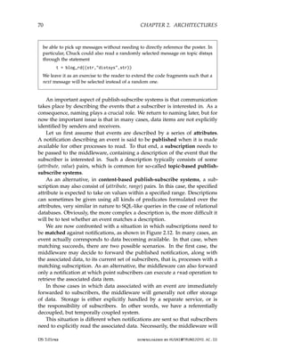
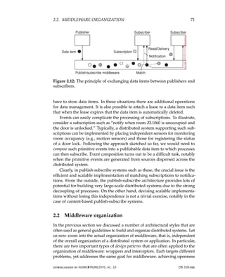
![72 CHAPTER 2. ARCHITECTURES
(as we discussed in Section 1.2). However, it can be argued that the ultimate
openness is achieved when we can compose middleware at runtime. We
briefly discuss component-based construction as a popular means toward
what Parlavantzas and Coulson [2007] refer to as modifiable middleware.
Wrappers
When building a distributed system out of existing components, we immedi-
ately bump into a fundamental problem: the interfaces offered by the legacy
component are most likely not suitable for all applications. In Section 1.3 we
discussed how enterprise application integration could be established through
middleware as a communication facilitator, but there we still implicitly as-
sumed that, in the end, components could be accessed through their native
interfaces.
A wrapper or adapter is a special component that offers an interface
acceptable to a client application, of which the functions are transformed
into those available at the component. In essence, it solves the problem of
incompatible interfaces (see also [Gamma et al., 1994]).
Although originally narrowly defined in the context of object-oriented
programming, in the context of distributed systems wrappers are much more
than simple interface transformers. For example, an object adapter is a
component that allows applications to invoke remote objects, although those
objects may have been implemented as a combination of library functions
operating on the tables of a relational database.
As another example, reconsider Amazon’s S3 storage service. There are
now two types of interfaces available, one adhering to a RESTful architecture,
another following a more traditional approach. For the RESTful interface,
clients will be using the HTTP protocol, essentially communicating with a
traditional Web server which now acts as an adapter to the actual storage
service, by partly dissecting incoming requests and subsequently handing
them off to specialized servers internal to S3.
Wrappers have always played an important role in extending systems with
existing components. Extensibility, which is crucial for achieving openness,
used to be addressed by adding wrappers as needed. In other words, if
application A managed data that was needed by application B, one approach
would be to develop a wrapper specific for B so that it could have access to
A’s data. Clearly, this approach does not scale well: with N applications we
would, in theory, need to develop N × (N − 1) = O(N2) wrappers.
Again, facilitating a reduction of the number of wrappers is typically
done through middleware. One way of doing this is implementing a so-
called broker, which is logically a centralized component that handles all
the accesses between different applications. An often-used type is a message
brokerwhich we discuss the technicalities in Section 4.3. In the case of a
message broker, applications simply send requests to the broker containing
DS 3.01pre downloaded by HUSNI@TRUNOJOYO.AC.ID
72 CHAPTER 2. ARCHITECTURES
(as we discussed in Section 1.2). However, it can be argued that the ultimate
openness is achieved when we can compose middleware at runtime. We
briefly discuss component-based construction as a popular means toward
what Parlavantzas and Coulson [2007] refer to as modifiable middleware.
Wrappers
When building a distributed system out of existing components, we immedi-
ately bump into a fundamental problem: the interfaces offered by the legacy
component are most likely not suitable for all applications. In Section 1.3 we
discussed how enterprise application integration could be established through
middleware as a communication facilitator, but there we still implicitly as-
sumed that, in the end, components could be accessed through their native
interfaces.
A wrapper or adapter is a special component that offers an interface
acceptable to a client application, of which the functions are transformed
into those available at the component. In essence, it solves the problem of
incompatible interfaces (see also [Gamma et al., 1994]).
Although originally narrowly defined in the context of object-oriented
programming, in the context of distributed systems wrappers are much more
than simple interface transformers. For example, an object adapter is a
component that allows applications to invoke remote objects, although those
objects may have been implemented as a combination of library functions
operating on the tables of a relational database.
As another example, reconsider Amazon’s S3 storage service. There are
now two types of interfaces available, one adhering to a RESTful architecture,
another following a more traditional approach. For the RESTful interface,
clients will be using the HTTP protocol, essentially communicating with a
traditional Web server which now acts as an adapter to the actual storage
service, by partly dissecting incoming requests and subsequently handing
them off to specialized servers internal to S3.
Wrappers have always played an important role in extending systems with
existing components. Extensibility, which is crucial for achieving openness,
used to be addressed by adding wrappers as needed. In other words, if
application A managed data that was needed by application B, one approach
would be to develop a wrapper specific for B so that it could have access to
A’s data. Clearly, this approach does not scale well: with N applications we
would, in theory, need to develop N × (N − 1) = O(N2) wrappers.
Again, facilitating a reduction of the number of wrappers is typically
done through middleware. One way of doing this is implementing a so-
called broker, which is logically a centralized component that handles all
the accesses between different applications. An often-used type is a message
brokerwhich we discuss the technicalities in Section 4.3. In the case of a
message broker, applications simply send requests to the broker containing
DS 3.01pre downloaded by HUSNI@TRUNOJOYO.AC.ID](https://image.slidesharecdn.com/distributed-systems-3rd-edition-251215232331-7e034da0/85/architectureec-distributed-systems-3rd-Edition-pdf-86-320.jpg)
![2.2. MIDDLEWARE ORGANIZATION 73
(a) (b)
Figure 2.13: (a) Requiring each application to have a wrapper for each other
application. (b) Reducing the number of wrappers by making use of a broker.
information on what they need. The broker, having knowledge of all relevant
applications, contacts the appropriate applications, possibly combines and
transforms the responses and returns the result to the initial application. In
principle, because a broker offers a single interface to each application, we
now need at most 2N = O(N) wrappers instead of O(N2). This situation is
sketched in Figure 2.13.
Interceptors
Conceptually, an interceptor is nothing but a software construct that will
break the usual flow of control and allow other (application specific) code
to be executed. Interceptors are a primary means for adapting middleware
to the specific needs of an application. As such, they play an important
role in making middleware open. To make interceptors generic may require
a substantial implementation effort, as illustrated in Schmidt et al. [2000]
and it is unclear whether in such cases generality should be preferred over
restricted applicability and simplicity. Also, in many cases having only
limited interception facilities will improve management of the software and
the distributed system as a whole.
To make matters concrete, consider interception as supported in many
object-based distributed systems. The basic idea is simple: an object A can call
a method that belongs to an object B, while the latter resides on a different
machine than A. As we explain in detail later in the book, such a remote-object
invocation is carried out in three steps:
1. Object A is offered a local interface that is exactly the same as the inter-
face offered by object B. A calls the method available in that interface.
2. The call by A is transformed into a generic object invocation, made
possible through a general object-invocation interface offered by the
middleware at the machine where A resides.
downloaded by HUSNI@TRUNOJOYO.AC.ID DS 3.01pre
2.2. MIDDLEWARE ORGANIZATION 73
(a) (b)
Figure 2.13: (a) Requiring each application to have a wrapper for each other
application. (b) Reducing the number of wrappers by making use of a broker.
information on what they need. The broker, having knowledge of all relevant
applications, contacts the appropriate applications, possibly combines and
transforms the responses and returns the result to the initial application. In
principle, because a broker offers a single interface to each application, we
now need at most 2N = O(N) wrappers instead of O(N2). This situation is
sketched in Figure 2.13.
Interceptors
Conceptually, an interceptor is nothing but a software construct that will
break the usual flow of control and allow other (application specific) code
to be executed. Interceptors are a primary means for adapting middleware
to the specific needs of an application. As such, they play an important
role in making middleware open. To make interceptors generic may require
a substantial implementation effort, as illustrated in Schmidt et al. [2000]
and it is unclear whether in such cases generality should be preferred over
restricted applicability and simplicity. Also, in many cases having only
limited interception facilities will improve management of the software and
the distributed system as a whole.
To make matters concrete, consider interception as supported in many
object-based distributed systems. The basic idea is simple: an object A can call
a method that belongs to an object B, while the latter resides on a different
machine than A. As we explain in detail later in the book, such a remote-object
invocation is carried out in three steps:
1. Object A is offered a local interface that is exactly the same as the inter-
face offered by object B. A calls the method available in that interface.
2. The call by A is transformed into a generic object invocation, made
possible through a general object-invocation interface offered by the
middleware at the machine where A resides.
downloaded by HUSNI@TRUNOJOYO.AC.ID DS 3.01pre](https://image.slidesharecdn.com/distributed-systems-3rd-edition-251215232331-7e034da0/85/architectureec-distributed-systems-3rd-Edition-pdf-87-320.jpg)
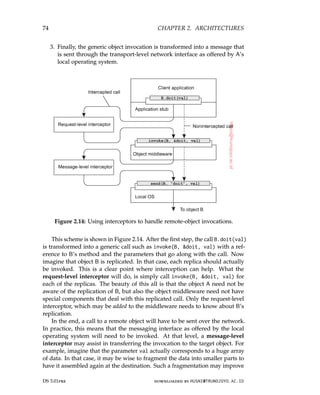
![2.2. MIDDLEWARE ORGANIZATION 75
performance or reliability. Again, the middleware need not be aware of this
fragmentation; the lower-level interceptor will transparently handle the rest of
the communication with the local operating system.
Modifiable middleware
What wrappers and interceptors offer are means to extend and adapt the
middleware. The need for adaptation comes from the fact that the environment
in which distributed applications are executed changes continuously. Changes
include those resulting from mobility, a strong variance in the quality-of-
service of networks, failing hardware, and battery drainage, amongst others.
Rather than making applications responsible for reacting to changes, this task
is placed in the middleware. Moreover, as the size of a distributed system
increases, changing its parts can rarely be done by temporarily shutting it
down. What is needed is being able to make changes on-the-fly.
These strong influences from the environment have brought many de-
signers of middleware to consider the construction of adaptive software. We
follow Parlavantzas and Coulson [2007] in speaking of modifiable middleware
to express that middleware may not only need to be adaptive, but that we
should be able to purposefully modify it without bringing it down. In this
context, interceptors can be thought of offering a means to adapt the standard
flow of control. Replacing software components at runtime is an example
of modifying a system. And indeed, perhaps one of the most popular ap-
proaches toward modifiable middleware is that of dynamically constructing
middleware from components.
Component-based design focuses on supporting modifiability through
composition. A system may either be configured statically at design time,
or dynamically at runtime. The latter requires support for late binding,
a technique that has been successfully applied in programming language
environments, but also for operating systems where modules can be loaded
and unloaded at will. Research is now well underway to automatically select
the best implementation of a component during runtime [Yellin, 2003] but
again, the process remains complex for distributed systems, especially when
considering that replacement of one component requires to know exactly what
the effect of that replacement on other components will be. In many cases,
components are less independent as one may think.
The bottom line is that in order to accommodate dynamic changes to the
software that makes up middleware, we need at least basic support to load
and unload components at runtime. In addition, for each component explicit
specifications of the interfaces it offers, as well the interfaces it requires, are
needed. If state is maintained between calls to a component, then further
special measures are needed. By-and-large, it should be clear that organizing
middleware to be modifiable requires very special attention.
downloaded by HUSNI@TRUNOJOYO.AC.ID DS 3.01pre
2.2. MIDDLEWARE ORGANIZATION 75
performance or reliability. Again, the middleware need not be aware of this
fragmentation; the lower-level interceptor will transparently handle the rest of
the communication with the local operating system.
Modifiable middleware
What wrappers and interceptors offer are means to extend and adapt the
middleware. The need for adaptation comes from the fact that the environment
in which distributed applications are executed changes continuously. Changes
include those resulting from mobility, a strong variance in the quality-of-
service of networks, failing hardware, and battery drainage, amongst others.
Rather than making applications responsible for reacting to changes, this task
is placed in the middleware. Moreover, as the size of a distributed system
increases, changing its parts can rarely be done by temporarily shutting it
down. What is needed is being able to make changes on-the-fly.
These strong influences from the environment have brought many de-
signers of middleware to consider the construction of adaptive software. We
follow Parlavantzas and Coulson [2007] in speaking of modifiable middleware
to express that middleware may not only need to be adaptive, but that we
should be able to purposefully modify it without bringing it down. In this
context, interceptors can be thought of offering a means to adapt the standard
flow of control. Replacing software components at runtime is an example
of modifying a system. And indeed, perhaps one of the most popular ap-
proaches toward modifiable middleware is that of dynamically constructing
middleware from components.
Component-based design focuses on supporting modifiability through
composition. A system may either be configured statically at design time,
or dynamically at runtime. The latter requires support for late binding,
a technique that has been successfully applied in programming language
environments, but also for operating systems where modules can be loaded
and unloaded at will. Research is now well underway to automatically select
the best implementation of a component during runtime [Yellin, 2003] but
again, the process remains complex for distributed systems, especially when
considering that replacement of one component requires to know exactly what
the effect of that replacement on other components will be. In many cases,
components are less independent as one may think.
The bottom line is that in order to accommodate dynamic changes to the
software that makes up middleware, we need at least basic support to load
and unload components at runtime. In addition, for each component explicit
specifications of the interfaces it offers, as well the interfaces it requires, are
needed. If state is maintained between calls to a component, then further
special measures are needed. By-and-large, it should be clear that organizing
middleware to be modifiable requires very special attention.
downloaded by HUSNI@TRUNOJOYO.AC.ID DS 3.01pre](https://image.slidesharecdn.com/distributed-systems-3rd-edition-251215232331-7e034da0/85/architectureec-distributed-systems-3rd-Edition-pdf-89-320.jpg)
![76 CHAPTER 2. ARCHITECTURES
2.3 System architecture
Now that we have briefly discussed some commonly applied architectural
styles, let us take a look at how many distributed systems are actually or-
ganized by considering where software components are placed. Deciding
on software components, their interaction, and their placement leads to an
instance of a software architecture, also known as a system architecture [Bass
et al., 2003]. We will discuss centralized and decentralized organizations, as
well as various hybrid forms.
Centralized organizations
Despite the lack of consensus on many distributed systems issues, there is
one issue that many researchers and practitioners agree upon: thinking in
terms of clients that request services from servers helps understanding and
managing the complexity of distributed systems [Saltzer and Kaashoek, 2009].
In the following, we first consider a simple layered organization, followed by
looking at multi-layered organizations.
Simple client-server architecture
In the basic client-server model, processes in a distributed system are divided
into two (possibly overlapping) groups. A server is a process implementing
a specific service, for example, a file system service or a database service. A
client is a process that requests a service from a server by sending it a request
and subsequently waiting for the server’s reply. This client-server interaction,
also known as request-reply behavior is shown in Figure 2.15 in the form of
a message sequence chart.
Figure 2.15: General interaction between a client and a server.
Communication between a client and a server can be implemented by
means of a simple connectionless protocol when the underlying network is
fairly reliable as in many local-area networks. In these cases, when a client
requests a service, it simply packages a message for the server, identifying the
service it wants, along with the necessary input data. The message is then
sent to the server. The latter, in turn, will always wait for an incoming request,
DS 3.01pre downloaded by HUSNI@TRUNOJOYO.AC.ID
76 CHAPTER 2. ARCHITECTURES
2.3 System architecture
Now that we have briefly discussed some commonly applied architectural
styles, let us take a look at how many distributed systems are actually or-
ganized by considering where software components are placed. Deciding
on software components, their interaction, and their placement leads to an
instance of a software architecture, also known as a system architecture [Bass
et al., 2003]. We will discuss centralized and decentralized organizations, as
well as various hybrid forms.
Centralized organizations
Despite the lack of consensus on many distributed systems issues, there is
one issue that many researchers and practitioners agree upon: thinking in
terms of clients that request services from servers helps understanding and
managing the complexity of distributed systems [Saltzer and Kaashoek, 2009].
In the following, we first consider a simple layered organization, followed by
looking at multi-layered organizations.
Simple client-server architecture
In the basic client-server model, processes in a distributed system are divided
into two (possibly overlapping) groups. A server is a process implementing
a specific service, for example, a file system service or a database service. A
client is a process that requests a service from a server by sending it a request
and subsequently waiting for the server’s reply. This client-server interaction,
also known as request-reply behavior is shown in Figure 2.15 in the form of
a message sequence chart.
Figure 2.15: General interaction between a client and a server.
Communication between a client and a server can be implemented by
means of a simple connectionless protocol when the underlying network is
fairly reliable as in many local-area networks. In these cases, when a client
requests a service, it simply packages a message for the server, identifying the
service it wants, along with the necessary input data. The message is then
sent to the server. The latter, in turn, will always wait for an incoming request,
DS 3.01pre downloaded by HUSNI@TRUNOJOYO.AC.ID](https://image.slidesharecdn.com/distributed-systems-3rd-edition-251215232331-7e034da0/85/architectureec-distributed-systems-3rd-Edition-pdf-90-320.jpg)
![78 CHAPTER 2. ARCHITECTURES
1. A client machine containing only the programs implementing (part of)
the user-interface level
2. A server machine containing the rest, that is, the programs implementing
the processing and data level
In this organization everything is handled by the server while the client is
essentially no more than a dumb terminal, possibly with only a convenient
graphical interface. There are, however, many other possibilities. As explained
in Section 2.1, many distributed applications are divided into the three layers
(1) user interface layer, (2) processing layer, and (3) data layer. One approach
for organizing clients and servers is then to distribute these layers across
different machines, as shown in Figure 2.16 (see also Umar [1997]). As
a first step, we make a distinction between only two kinds of machines:
client machines and server machines, leading to what is also referred to as a
(physically) two-tiered architecture.
(a) (b) (c) (d) (e)
Figure 2.16: Client-server organizations in a two-tiered architecture.
One possible organization is to have only the terminal-dependent part
of the user interface on the client machine, as shown in Figure 2.16(a), and
give the applications remote control over the presentation of their data. An
alternative is to place the entire user-interface software on the client side, as
shown in Figure 2.16(b). In such cases, we essentially divide the application
into a graphical front end, which communicates with the rest of the application
(residing at the server) through an application-specific protocol. In this model,
the front end (the client software) does no processing other than necessary for
presenting the application’s interface.
Continuing along this line of reasoning, we may also move part of the
application to the front end, as shown in Figure 2.16(c). An example where
this makes sense is where the application makes use of a form that needs to
be filled in entirely before it can be processed. The front end can then check
DS 3.01pre downloaded by HUSNI@TRUNOJOYO.AC.ID
78 CHAPTER 2. ARCHITECTURES
1. A client machine containing only the programs implementing (part of)
the user-interface level
2. A server machine containing the rest, that is, the programs implementing
the processing and data level
In this organization everything is handled by the server while the client is
essentially no more than a dumb terminal, possibly with only a convenient
graphical interface. There are, however, many other possibilities. As explained
in Section 2.1, many distributed applications are divided into the three layers
(1) user interface layer, (2) processing layer, and (3) data layer. One approach
for organizing clients and servers is then to distribute these layers across
different machines, as shown in Figure 2.16 (see also Umar [1997]). As
a first step, we make a distinction between only two kinds of machines:
client machines and server machines, leading to what is also referred to as a
(physically) two-tiered architecture.
(a) (b) (c) (d) (e)
Figure 2.16: Client-server organizations in a two-tiered architecture.
One possible organization is to have only the terminal-dependent part
of the user interface on the client machine, as shown in Figure 2.16(a), and
give the applications remote control over the presentation of their data. An
alternative is to place the entire user-interface software on the client side, as
shown in Figure 2.16(b). In such cases, we essentially divide the application
into a graphical front end, which communicates with the rest of the application
(residing at the server) through an application-specific protocol. In this model,
the front end (the client software) does no processing other than necessary for
presenting the application’s interface.
Continuing along this line of reasoning, we may also move part of the
application to the front end, as shown in Figure 2.16(c). An example where
this makes sense is where the application makes use of a form that needs to
be filled in entirely before it can be processed. The front end can then check
DS 3.01pre downloaded by HUSNI@TRUNOJOYO.AC.ID](https://image.slidesharecdn.com/distributed-systems-3rd-edition-251215232331-7e034da0/85/architectureec-distributed-systems-3rd-Edition-pdf-92-320.jpg)
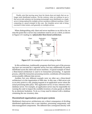
![2.3. SYSTEM ARCHITECTURE 81
the logical organization of applications. In many business environments,
distributed processing is equivalent to organizing a client-server application
as a multitiered architecture. We refer to this type of distribution as vertical
distribution. The characteristic feature of vertical distribution is that it is
achieved by placing logically different components on different machines. The
term is related to the concept of vertical fragmentation as used in distributed
relational databases, where it means that tables are split columnwise, and
subsequently distributed across multiple machines [Özsu and Valduriez, 2011].
Again, from a systems-management perspective, having a vertical distri-
bution can help: functions are logically and physically split across multiple
machines, where each machine is tailored to a specific group of functions.
However, vertical distribution is only one way of organizing client-server
applications. In modern architectures, it is often the distribution of the clients
and the servers that counts, which we refer to as horizontal distribution. In
this type of distribution, a client or server may be physically split up into
logically equivalent parts, but each part is operating on its own share of the
complete data set, thus balancing the load. In this section we will take a look
at a class of modern system architectures that support horizontal distribution,
known as peer-to-peer systems.
From a high-level perspective, the processes that constitute a peer-to-peer
system are all equal. This means that the functions that need to be carried
out are represented by every process that constitutes the distributed system.
As a consequence, much of the interaction between processes is symmetric:
each process will act as a client and a server at the same time (which is also
referred to as acting as a servant).
Given this symmetric behavior, peer-to-peer architectures evolve around
the question how to organize the processes in an overlay network [Tarkoma,
2010]: a network in which the nodes are formed by the processes and the links
represent the possible communication channels (which are often realized as
TCP connections). A node may not be able to communicate directly with an
arbitrary other node, but is required to send messages through the available
communication channels. Two types of overlay networks exist: those that are
structured and those that are not. These two types are surveyed extensively
in Lua et al. [2005] along with numerous examples. Buford and Yu [2010]
additionally includes an extensive list of various peer-to-peer systems. Aberer
et al. [2005] provide a reference architecture that allows for a more formal
comparison of the different types of peer-to-peer systems. A survey taken
from the perspective of content distribution is provided by Androutsellis-
Theotokis and Spinellis [2004]. Finally, Buford et al. [2009], Tarkoma [2010]
and Vu et al. [2010] go beyond the level of surveys and form adequate text
books for initial or further study.
downloaded by HUSNI@TRUNOJOYO.AC.ID DS 3.01pre
2.3. SYSTEM ARCHITECTURE 81
the logical organization of applications. In many business environments,
distributed processing is equivalent to organizing a client-server application
as a multitiered architecture. We refer to this type of distribution as vertical
distribution. The characteristic feature of vertical distribution is that it is
achieved by placing logically different components on different machines. The
term is related to the concept of vertical fragmentation as used in distributed
relational databases, where it means that tables are split columnwise, and
subsequently distributed across multiple machines [Özsu and Valduriez, 2011].
Again, from a systems-management perspective, having a vertical distri-
bution can help: functions are logically and physically split across multiple
machines, where each machine is tailored to a specific group of functions.
However, vertical distribution is only one way of organizing client-server
applications. In modern architectures, it is often the distribution of the clients
and the servers that counts, which we refer to as horizontal distribution. In
this type of distribution, a client or server may be physically split up into
logically equivalent parts, but each part is operating on its own share of the
complete data set, thus balancing the load. In this section we will take a look
at a class of modern system architectures that support horizontal distribution,
known as peer-to-peer systems.
From a high-level perspective, the processes that constitute a peer-to-peer
system are all equal. This means that the functions that need to be carried
out are represented by every process that constitutes the distributed system.
As a consequence, much of the interaction between processes is symmetric:
each process will act as a client and a server at the same time (which is also
referred to as acting as a servant).
Given this symmetric behavior, peer-to-peer architectures evolve around
the question how to organize the processes in an overlay network [Tarkoma,
2010]: a network in which the nodes are formed by the processes and the links
represent the possible communication channels (which are often realized as
TCP connections). A node may not be able to communicate directly with an
arbitrary other node, but is required to send messages through the available
communication channels. Two types of overlay networks exist: those that are
structured and those that are not. These two types are surveyed extensively
in Lua et al. [2005] along with numerous examples. Buford and Yu [2010]
additionally includes an extensive list of various peer-to-peer systems. Aberer
et al. [2005] provide a reference architecture that allows for a more formal
comparison of the different types of peer-to-peer systems. A survey taken
from the perspective of content distribution is provided by Androutsellis-
Theotokis and Spinellis [2004]. Finally, Buford et al. [2009], Tarkoma [2010]
and Vu et al. [2010] go beyond the level of surveys and form adequate text
books for initial or further study.
downloaded by HUSNI@TRUNOJOYO.AC.ID DS 3.01pre](https://image.slidesharecdn.com/distributed-systems-3rd-edition-251215232331-7e034da0/85/architectureec-distributed-systems-3rd-Edition-pdf-95-320.jpg)
![82 CHAPTER 2. ARCHITECTURES
Structured peer-to-peer systems
As its name suggests, in a structured peer-to-peer system the nodes (i.e.,
processes) are organized in an overlay that adheres to a specific, deterministic
topology: a ring, a binary tree, a grid, etc. This topology is used to efficiently
look up data. Characteristic for structured peer-to-peer systems, is that they
are generally based on using a so-called semantic-free index. What this means
is that each data item that is to be maintained by the system, is uniquely
associated with a key, and that this key is subsequently used as an index. To
this end, it is common to use a hash function, so that we get:
key(data item) = hash(data item’s value).
The peer-to-peer system as a whole is now responsible for storing (key,value)
pairs. To this end, each node is assigned an identifier from the same set
of all possible hash values, and each node is made responsible for storing
data associated with a specific subset of keys. In essence, the system is
thus seen to implement a distributed hash table, generally abbreviated to a
DHT [Balakrishnan et al., 2003].
Following this approach now reduces the essence of structured peer-to-
peer systems to being able to look up a data item by means of its key. That
is, the system provides an efficient implementation of a function lookup that
maps a key to an existing node:
existing node = lookup(key).
This is where the topology of a structured peer-to-peer system plays a crucial
role. Any node can be asked to look up a given key, which then boils down to
efficiently routing that lookup request to the node responsible for storing the
data associated with the given key.
To clarify these matters, let us consider a simple peer-to-peer system with
a fixed number of nodes, organized into a hypercube. A hypercube is an
n-dimensional cube. The hypercube shown in Figure 2.18 is four-dimensional.
It can be thought of as two ordinary cubes, each with 8 vertices and 12 edges.
To expand the hypercube to five dimensions, we would add another set of
two interconnected cubes to the figure, connect the corresponding edges in
the two halves, and so on.
For this (admittedly naive) system, each data item is associated with one
of the 16 nodes. This can be achieved by hashing the value of a data item to a
key k ∈ {0, 1, 2, . . . , 24 − 1}. Now suppose that the node with identifier 0111
is requested to look up the data having key 14, corresponding to the binary
value 1110. In this example, we assume that the node with identifier 1110 is
responsible for storing all data items that have key 14. What node 0111 can
simply do, is forward the request to a neighbor that is closer to node 1110.
In this case, this is either node 0110 or node 1111. If it picks node 0110, that
DS 3.01pre downloaded by HUSNI@TRUNOJOYO.AC.ID
82 CHAPTER 2. ARCHITECTURES
Structured peer-to-peer systems
As its name suggests, in a structured peer-to-peer system the nodes (i.e.,
processes) are organized in an overlay that adheres to a specific, deterministic
topology: a ring, a binary tree, a grid, etc. This topology is used to efficiently
look up data. Characteristic for structured peer-to-peer systems, is that they
are generally based on using a so-called semantic-free index. What this means
is that each data item that is to be maintained by the system, is uniquely
associated with a key, and that this key is subsequently used as an index. To
this end, it is common to use a hash function, so that we get:
key(data item) = hash(data item’s value).
The peer-to-peer system as a whole is now responsible for storing (key,value)
pairs. To this end, each node is assigned an identifier from the same set
of all possible hash values, and each node is made responsible for storing
data associated with a specific subset of keys. In essence, the system is
thus seen to implement a distributed hash table, generally abbreviated to a
DHT [Balakrishnan et al., 2003].
Following this approach now reduces the essence of structured peer-to-
peer systems to being able to look up a data item by means of its key. That
is, the system provides an efficient implementation of a function lookup that
maps a key to an existing node:
existing node = lookup(key).
This is where the topology of a structured peer-to-peer system plays a crucial
role. Any node can be asked to look up a given key, which then boils down to
efficiently routing that lookup request to the node responsible for storing the
data associated with the given key.
To clarify these matters, let us consider a simple peer-to-peer system with
a fixed number of nodes, organized into a hypercube. A hypercube is an
n-dimensional cube. The hypercube shown in Figure 2.18 is four-dimensional.
It can be thought of as two ordinary cubes, each with 8 vertices and 12 edges.
To expand the hypercube to five dimensions, we would add another set of
two interconnected cubes to the figure, connect the corresponding edges in
the two halves, and so on.
For this (admittedly naive) system, each data item is associated with one
of the 16 nodes. This can be achieved by hashing the value of a data item to a
key k ∈ {0, 1, 2, . . . , 24 − 1}. Now suppose that the node with identifier 0111
is requested to look up the data having key 14, corresponding to the binary
value 1110. In this example, we assume that the node with identifier 1110 is
responsible for storing all data items that have key 14. What node 0111 can
simply do, is forward the request to a neighbor that is closer to node 1110.
In this case, this is either node 0110 or node 1111. If it picks node 0110, that
DS 3.01pre downloaded by HUSNI@TRUNOJOYO.AC.ID](https://image.slidesharecdn.com/distributed-systems-3rd-edition-251215232331-7e034da0/85/architectureec-distributed-systems-3rd-Edition-pdf-96-320.jpg)
![2.3. SYSTEM ARCHITECTURE 83
Figure 2.18: A simple peer-to-peer system organized as a four-dimensional
hypercube.
node will then forward the request directly to node 1110 from where the data
can be retrieved.
Note 2.5 (Example: The Chord system)
Figure 2.19: The organization of nodes and data items in Chord.
The previous example illustrates two things: (1) the use of a hashing function
to identify the node responsible for storing some data item, and (2) the routing
along the topology of a peer-to-peer system when looking up a data item given
its key. However, it is not a very realistic example, if only for the reason that we
assumed that the total set of nodes is fixed. Let us therefore consider a more
realistic example of a structured peer-to-peer system that is also used in practice.
In the Chord system [Stoica et al., 2003] the nodes are logically organized
in a ring such that a data item with an m-bit key k is mapped to the node with
the smallest (again, also m bit) identifier id ≥ k. This node is referred to as the
successor of key k and denoted as succ(k). Keys and identifiers are typically 128
downloaded by HUSNI@TRUNOJOYO.AC.ID DS 3.01pre
2.3. SYSTEM ARCHITECTURE 83
Figure 2.18: A simple peer-to-peer system organized as a four-dimensional
hypercube.
node will then forward the request directly to node 1110 from where the data
can be retrieved.
Note 2.5 (Example: The Chord system)
Figure 2.19: The organization of nodes and data items in Chord.
The previous example illustrates two things: (1) the use of a hashing function
to identify the node responsible for storing some data item, and (2) the routing
along the topology of a peer-to-peer system when looking up a data item given
its key. However, it is not a very realistic example, if only for the reason that we
assumed that the total set of nodes is fixed. Let us therefore consider a more
realistic example of a structured peer-to-peer system that is also used in practice.
In the Chord system [Stoica et al., 2003] the nodes are logically organized
in a ring such that a data item with an m-bit key k is mapped to the node with
the smallest (again, also m bit) identifier id ≥ k. This node is referred to as the
successor of key k and denoted as succ(k). Keys and identifiers are typically 128
downloaded by HUSNI@TRUNOJOYO.AC.ID DS 3.01pre](https://image.slidesharecdn.com/distributed-systems-3rd-edition-251215232331-7e034da0/85/architectureec-distributed-systems-3rd-Edition-pdf-97-320.jpg)
![84 CHAPTER 2. ARCHITECTURES
or 160 bits long. Figure 2.19 shows a much smaller Chord ring, where m = 5 and
with nine nodes {1, 4, 9, 11, 14, 18, 20, 21, 28}. The successor of key 7 is equal to
9. Likewise, succ(5) = 9, but also succ(9) = 9. In Chord, each node maintains
shortcuts to other nodes. A shortcut appears as a directed edge from one node
to another. How these shortcuts are constructed is explained in Chapter 5. The
construction is done in such a way that the length of the shortest path between
any pair of nodes is of order O(log N), where N is the total number of nodes.
To look up a key, a node will try to forward the request “as far as possible,” but
without passing it beyond the node responsible for that key. To clarify, suppose
that in our example Chord ring, node 9 is asked to look up the node responsible
for key 3 (which is node 4). Node 9 has four shortcuts: to nodes 11, 14, 18, and 28,
respectively. As node 28 is the farthest node 9 knows about and still preceding
the one responsible for key 3, it will get the lookup request. Node 28 has three
shortcuts: to nodes 1, 4, and 14, respectively. Note that node 28 has no knowledge
about the existence of nodes between nodes 1 and 4. For this reason, the best
what it can do is forward the request to node 1. The latter knows that its successor
in the ring is node 4, and thus that this is the node responsible for key 3, to which
it will subsequently forward the request.
Now suppose that a node, with the unique identifier u, wants to join a Chord
overlay. To that end, it contacts an arbitrary node and requests it to look up u,
that is, return the value v= succ(u). At that point, node u will simply need to
insert itself between the predecessor of v and v itself, thus becoming the new
predecessor of v. During this process, shortcuts from u to other nodes will be
established, but also some existing ones previously directed toward v will now be
adjusted to point to u (again, details are deferred until later chapters). Obviously,
any data item with key k stored at v but for which succ(k) is now equal to u is
transferred from v to u.
Leaving is just as simple: node u informs its departure to its predecessor and
successor, and transfers its data items to succ(u).
Unstructured peer-to-peer systems
Structured peer-to-peer systems attempt to maintain a specific, deterministic
overlay network. In contrast, in an unstructured peer-to-peer system each
node maintains an ad hoc list of neighbors. The resulting overlay resembles
what is known as a random graph: a graph in which an edge hu, vi between
two nodes u and v exists only with a certain probability P[hu, vi]. Ideally, this
probability is the same for all pairs of nodes, but in practice a wide range of
distributions is observed.
In an unstructured peer-to-peer system, when a node joins it often contacts
a well-known node to obtain a starting list of other peers in the system. This
list can then be used to find more peers, and perhaps ignore others, and so
on. In practice, a node generally changes its local list almost continuously.
For example, a node may discover that a neighbor is no longer responsive
DS 3.01pre downloaded by HUSNI@TRUNOJOYO.AC.ID
84 CHAPTER 2. ARCHITECTURES
or 160 bits long. Figure 2.19 shows a much smaller Chord ring, where m = 5 and
with nine nodes {1, 4, 9, 11, 14, 18, 20, 21, 28}. The successor of key 7 is equal to
9. Likewise, succ(5) = 9, but also succ(9) = 9. In Chord, each node maintains
shortcuts to other nodes. A shortcut appears as a directed edge from one node
to another. How these shortcuts are constructed is explained in Chapter 5. The
construction is done in such a way that the length of the shortest path between
any pair of nodes is of order O(log N), where N is the total number of nodes.
To look up a key, a node will try to forward the request “as far as possible,” but
without passing it beyond the node responsible for that key. To clarify, suppose
that in our example Chord ring, node 9 is asked to look up the node responsible
for key 3 (which is node 4). Node 9 has four shortcuts: to nodes 11, 14, 18, and 28,
respectively. As node 28 is the farthest node 9 knows about and still preceding
the one responsible for key 3, it will get the lookup request. Node 28 has three
shortcuts: to nodes 1, 4, and 14, respectively. Note that node 28 has no knowledge
about the existence of nodes between nodes 1 and 4. For this reason, the best
what it can do is forward the request to node 1. The latter knows that its successor
in the ring is node 4, and thus that this is the node responsible for key 3, to which
it will subsequently forward the request.
Now suppose that a node, with the unique identifier u, wants to join a Chord
overlay. To that end, it contacts an arbitrary node and requests it to look up u,
that is, return the value v= succ(u). At that point, node u will simply need to
insert itself between the predecessor of v and v itself, thus becoming the new
predecessor of v. During this process, shortcuts from u to other nodes will be
established, but also some existing ones previously directed toward v will now be
adjusted to point to u (again, details are deferred until later chapters). Obviously,
any data item with key k stored at v but for which succ(k) is now equal to u is
transferred from v to u.
Leaving is just as simple: node u informs its departure to its predecessor and
successor, and transfers its data items to succ(u).
Unstructured peer-to-peer systems
Structured peer-to-peer systems attempt to maintain a specific, deterministic
overlay network. In contrast, in an unstructured peer-to-peer system each
node maintains an ad hoc list of neighbors. The resulting overlay resembles
what is known as a random graph: a graph in which an edge hu, vi between
two nodes u and v exists only with a certain probability P[hu, vi]. Ideally, this
probability is the same for all pairs of nodes, but in practice a wide range of
distributions is observed.
In an unstructured peer-to-peer system, when a node joins it often contacts
a well-known node to obtain a starting list of other peers in the system. This
list can then be used to find more peers, and perhaps ignore others, and so
on. In practice, a node generally changes its local list almost continuously.
For example, a node may discover that a neighbor is no longer responsive
DS 3.01pre downloaded by HUSNI@TRUNOJOYO.AC.ID](https://image.slidesharecdn.com/distributed-systems-3rd-edition-251215232331-7e034da0/85/architectureec-distributed-systems-3rd-Edition-pdf-98-320.jpg)
![2.3. SYSTEM ARCHITECTURE 85
and that it needs to be replaced. There may be other reasons, which we will
describe shortly.
Unlike structured peer-to-peer systems, looking up data cannot follow a
predetermined route when lists of neighbors are constructed in an ad hoc
fashion. Instead, in an unstructured peer-to-peer systems we really need
to resort to searching for data [Risson and Moors, 2006]. Let us look at two
extremes and consider the case in which we are requested to search for specific
data (e.g., identified by keywords).
Flooding: In the case of flooding, an issuing node u simply passes a request
for a data item to all its neighbors. A request will be ignored when its
receiving node, say v, had seen it before. Otherwise, v searches locally
for the requested data item. If v has the required data, it can either
respond directly to the issuing node u, or send it back to the original
forwarder, who will then return it to its original forwarder, and so on. If
v does not have the requested data, it forwards the request to all of its
own neighbors.
Obviously, flooding can be very expensive, for which reason a request
often has an associated time-to-live or TTL value, giving the maximum
number of hops a request is allowed to be forwarded. Choosing the
right TTL value is crucial: too small means that a request will stay close
to the issuer and may thus not reach a node having the data. Too large
incurs high communication costs.
As an alternative to setting TTL values, a node can also start a search
with an initial TTL value of 1, meaning that it will first query only its
neighbors. If no, or not enough results are returned, the TTL is increased
and a new search is initiated.
Random walks: At the other end of the search spectrum, an issuing node u
can simply try to find a data item by asking a randomly chosen neighbor,
say v. If v does not have the data, it forwards the request to one of its
randomly chosen neighbors, and so on. The result is known as a random
walk [Gkantsidis et al., 2006; Lv et al., 2002]. Obviously, a random walk
imposes much less network traffic, yet it may take much longer before
a node is reached that has the requested data. To decrease the waiting
time, an issuer can simply start n random walks simultaneously. Indeed,
studies show that in this case, the time it takes before reaching a node
that has the data drops approximately by a factor n. Lv et al. [2002]
report that relatively small values of n, such as 16 or 64, turn out to be
effective.
A random walk also needs to be stopped. To this end, we can either again
use a TTL, or alternatively, when a node receives a lookup request, check
with the issuer whether forwarding the request to another randomly
selected neighbor is still needed.
downloaded by HUSNI@TRUNOJOYO.AC.ID DS 3.01pre
2.3. SYSTEM ARCHITECTURE 85
and that it needs to be replaced. There may be other reasons, which we will
describe shortly.
Unlike structured peer-to-peer systems, looking up data cannot follow a
predetermined route when lists of neighbors are constructed in an ad hoc
fashion. Instead, in an unstructured peer-to-peer systems we really need
to resort to searching for data [Risson and Moors, 2006]. Let us look at two
extremes and consider the case in which we are requested to search for specific
data (e.g., identified by keywords).
Flooding: In the case of flooding, an issuing node u simply passes a request
for a data item to all its neighbors. A request will be ignored when its
receiving node, say v, had seen it before. Otherwise, v searches locally
for the requested data item. If v has the required data, it can either
respond directly to the issuing node u, or send it back to the original
forwarder, who will then return it to its original forwarder, and so on. If
v does not have the requested data, it forwards the request to all of its
own neighbors.
Obviously, flooding can be very expensive, for which reason a request
often has an associated time-to-live or TTL value, giving the maximum
number of hops a request is allowed to be forwarded. Choosing the
right TTL value is crucial: too small means that a request will stay close
to the issuer and may thus not reach a node having the data. Too large
incurs high communication costs.
As an alternative to setting TTL values, a node can also start a search
with an initial TTL value of 1, meaning that it will first query only its
neighbors. If no, or not enough results are returned, the TTL is increased
and a new search is initiated.
Random walks: At the other end of the search spectrum, an issuing node u
can simply try to find a data item by asking a randomly chosen neighbor,
say v. If v does not have the data, it forwards the request to one of its
randomly chosen neighbors, and so on. The result is known as a random
walk [Gkantsidis et al., 2006; Lv et al., 2002]. Obviously, a random walk
imposes much less network traffic, yet it may take much longer before
a node is reached that has the requested data. To decrease the waiting
time, an issuer can simply start n random walks simultaneously. Indeed,
studies show that in this case, the time it takes before reaching a node
that has the data drops approximately by a factor n. Lv et al. [2002]
report that relatively small values of n, such as 16 or 64, turn out to be
effective.
A random walk also needs to be stopped. To this end, we can either again
use a TTL, or alternatively, when a node receives a lookup request, check
with the issuer whether forwarding the request to another randomly
selected neighbor is still needed.
downloaded by HUSNI@TRUNOJOYO.AC.ID DS 3.01pre](https://image.slidesharecdn.com/distributed-systems-3rd-edition-251215232331-7e034da0/85/architectureec-distributed-systems-3rd-Edition-pdf-99-320.jpg)
![86 CHAPTER 2. ARCHITECTURES
Note that neither method relies on a specific comparison technique to decide
when requested data has been found. For structured peer-to-peer systems,
we assumed the use of keys for comparison; for the two approaches just
described, any comparison technique would suffice.
Between flooding and random walks lie policy-based search methods.
For example, a node may decide to keep track of peers who responded
positively, effectively turning them into preferred neighbors for succeeding
queries. Likewise, we may want to restrict flooding to fewer neighbors, but in
any case give preference to neighbors having many neighbors themselves.
Note 2.6 (Advanced: Flooding versus random walks)
When giving the matter some thought, it may come as a surprise that people have
even considered a random walk as an alternative way to search. At first instance,
it would seem like a technique resembling the search for a needle in a haystack.
However, we need to realize that in practice we are dealing with replicated data,
and even for very small replication factors and different replication distributions,
studies show that deploying random walks is not only effective, it can also be
much more efficient in comparison to flooding.
To see why, we closely follow the model described in Lv et al. [2002] and
Cohen and Shenker [2002]. Assume there are a total of N nodes and that each data
item is replicated across r randomly chosen nodes. A search consists of repeatedly
selecting a node at random until the item is found. If P[k] is the probability that
the item is found after k attempts, we have
P[k] =
r
N
(1 −
r
N
)k−1
.
Let the average search size S be the expected number of nodes that need to be
probed before finding the requested data item:
S =
N
∑
k=1
k · P[k] =
N
∑
k=1
k ·
r
N
(1 −
r
N
)k−1
≈ N/r for 1 r ≤ N.
By simply replicating every data item to each node, S = 1 and it is clear that a
random walk will always outperform flooding even for TTL values of 1. More
realistically, however, is to assume that r/N is relatively low, such as 0.1%,
meaning that the average search size would be approximately 1000 nodes.
To compare this to flooding, assume that each node, on average, forwards a
request to d randomly selected neighbors. After one step, the request will have
arrived at d nodes, each of who will forward it to another d − 1 nodes (assuming
that the node from where the request came is skipped), and so on. In other words,
after k steps, and taking into account that a node can receive the request more
than once, we will have reached (at most)
R(k) = d(d − 1)k−1
nodes. Various studies show that R(k) is a good estimate for the actual number of
nodes reached, as long as we have only a few number of flooding steps. Of these
DS 3.01pre downloaded by HUSNI@TRUNOJOYO.AC.ID
86 CHAPTER 2. ARCHITECTURES
Note that neither method relies on a specific comparison technique to decide
when requested data has been found. For structured peer-to-peer systems,
we assumed the use of keys for comparison; for the two approaches just
described, any comparison technique would suffice.
Between flooding and random walks lie policy-based search methods.
For example, a node may decide to keep track of peers who responded
positively, effectively turning them into preferred neighbors for succeeding
queries. Likewise, we may want to restrict flooding to fewer neighbors, but in
any case give preference to neighbors having many neighbors themselves.
Note 2.6 (Advanced: Flooding versus random walks)
When giving the matter some thought, it may come as a surprise that people have
even considered a random walk as an alternative way to search. At first instance,
it would seem like a technique resembling the search for a needle in a haystack.
However, we need to realize that in practice we are dealing with replicated data,
and even for very small replication factors and different replication distributions,
studies show that deploying random walks is not only effective, it can also be
much more efficient in comparison to flooding.
To see why, we closely follow the model described in Lv et al. [2002] and
Cohen and Shenker [2002]. Assume there are a total of N nodes and that each data
item is replicated across r randomly chosen nodes. A search consists of repeatedly
selecting a node at random until the item is found. If P[k] is the probability that
the item is found after k attempts, we have
P[k] =
r
N
(1 −
r
N
)k−1
.
Let the average search size S be the expected number of nodes that need to be
probed before finding the requested data item:
S =
N
∑
k=1
k · P[k] =
N
∑
k=1
k ·
r
N
(1 −
r
N
)k−1
≈ N/r for 1 r ≤ N.
By simply replicating every data item to each node, S = 1 and it is clear that a
random walk will always outperform flooding even for TTL values of 1. More
realistically, however, is to assume that r/N is relatively low, such as 0.1%,
meaning that the average search size would be approximately 1000 nodes.
To compare this to flooding, assume that each node, on average, forwards a
request to d randomly selected neighbors. After one step, the request will have
arrived at d nodes, each of who will forward it to another d − 1 nodes (assuming
that the node from where the request came is skipped), and so on. In other words,
after k steps, and taking into account that a node can receive the request more
than once, we will have reached (at most)
R(k) = d(d − 1)k−1
nodes. Various studies show that R(k) is a good estimate for the actual number of
nodes reached, as long as we have only a few number of flooding steps. Of these
DS 3.01pre downloaded by HUSNI@TRUNOJOYO.AC.ID](https://image.slidesharecdn.com/distributed-systems-3rd-edition-251215232331-7e034da0/85/architectureec-distributed-systems-3rd-Edition-pdf-100-320.jpg)
![2.3. SYSTEM ARCHITECTURE 87
nodes, we can expect a fraction of r/N to have the requested data item, meaning
that when r
N · R(k) ≥ 1, we will most likely have found a node that has the data
item.
To illustrate, let r/N = 0.001 = 0.1%, which means that S ≈ 1000. With
flooding to, on average, d = 10 neighbors, we would require at least 4 flooding
steps, reaching some 7290 nodes, which is considerably more that the 1000 nodes
required when using a random walk. Only with d = 33 will we need to contact
approximately also 1000 nodes in k = 2 flooding steps and having r/N · R(k) ≥ 1.
The obvious drawback of deploying random walks, is that it may take much
longer before an answer is returned.
Hierarchically organized peer-to-peer networks
Notably in unstructured peer-to-peer systems, locating relevant data items
can become problematic as the network grows. The reason for this scalability
problem is simple: as there is no deterministic way of routing a lookup request
to a specific data item, essentially the only technique a node can resort to is
searching for the request by means of flooding or randomly walking through
the network. As an alternative many peer-to-peer systems have proposed to
make use of special nodes that maintain an index of data items.
There are other situations in which abandoning the symmetric nature
of peer-to-peer systems is sensible. Consider a collaboration of nodes that
offer resources to each other. For example, in a collaborative content delivery
network (CDN), nodes may offer storage for hosting copies of Web documents
allowing Web clients to access pages nearby, and thus to access them quickly.
What is needed is a means to find out where documents can be stored best.
In that case, making use of a broker that collects data on resource usage and
availability for a number of nodes that are in each other’s proximity will allow
to quickly select a node with sufficient resources.
Nodes such as those maintaining an index or acting as a broker are gener-
ally referred to as super peers. As the name suggests, super peers are often
also organized in a peer-to-peer network, leading to a hierarchical organiza-
tion as explained in Yang and Garcia-Molina [2003]. A simple example of such
an organization is shown in Figure 2.20. In this organization, every regular
peer, now referred to as a weak peer, is connected as a client to a super peer.
All communication from and to a weak peer proceeds through that peer’s
associated super peer.
In many cases, the association between a weak peer and its super peer
is fixed: whenever a weak peer joins the network, it attaches to one of the
super peers and remains attached until it leaves the network. Obviously, it is
expected that super peers are long-lived processes with high availability. To
compensate for potential unstable behavior of a super peer, backup schemes
downloaded by HUSNI@TRUNOJOYO.AC.ID DS 3.01pre
2.3. SYSTEM ARCHITECTURE 87
nodes, we can expect a fraction of r/N to have the requested data item, meaning
that when r
N · R(k) ≥ 1, we will most likely have found a node that has the data
item.
To illustrate, let r/N = 0.001 = 0.1%, which means that S ≈ 1000. With
flooding to, on average, d = 10 neighbors, we would require at least 4 flooding
steps, reaching some 7290 nodes, which is considerably more that the 1000 nodes
required when using a random walk. Only with d = 33 will we need to contact
approximately also 1000 nodes in k = 2 flooding steps and having r/N · R(k) ≥ 1.
The obvious drawback of deploying random walks, is that it may take much
longer before an answer is returned.
Hierarchically organized peer-to-peer networks
Notably in unstructured peer-to-peer systems, locating relevant data items
can become problematic as the network grows. The reason for this scalability
problem is simple: as there is no deterministic way of routing a lookup request
to a specific data item, essentially the only technique a node can resort to is
searching for the request by means of flooding or randomly walking through
the network. As an alternative many peer-to-peer systems have proposed to
make use of special nodes that maintain an index of data items.
There are other situations in which abandoning the symmetric nature
of peer-to-peer systems is sensible. Consider a collaboration of nodes that
offer resources to each other. For example, in a collaborative content delivery
network (CDN), nodes may offer storage for hosting copies of Web documents
allowing Web clients to access pages nearby, and thus to access them quickly.
What is needed is a means to find out where documents can be stored best.
In that case, making use of a broker that collects data on resource usage and
availability for a number of nodes that are in each other’s proximity will allow
to quickly select a node with sufficient resources.
Nodes such as those maintaining an index or acting as a broker are gener-
ally referred to as super peers. As the name suggests, super peers are often
also organized in a peer-to-peer network, leading to a hierarchical organiza-
tion as explained in Yang and Garcia-Molina [2003]. A simple example of such
an organization is shown in Figure 2.20. In this organization, every regular
peer, now referred to as a weak peer, is connected as a client to a super peer.
All communication from and to a weak peer proceeds through that peer’s
associated super peer.
In many cases, the association between a weak peer and its super peer
is fixed: whenever a weak peer joins the network, it attaches to one of the
super peers and remains attached until it leaves the network. Obviously, it is
expected that super peers are long-lived processes with high availability. To
compensate for potential unstable behavior of a super peer, backup schemes
downloaded by HUSNI@TRUNOJOYO.AC.ID DS 3.01pre](https://image.slidesharecdn.com/distributed-systems-3rd-edition-251215232331-7e034da0/85/architectureec-distributed-systems-3rd-Edition-pdf-101-320.jpg)
![88 CHAPTER 2. ARCHITECTURES
Figure 2.20: A hierarchical organization of nodes into a super-peer network.
can be deployed, such as pairing every super peer with another one and
requiring weak peers to attach to both.
Having a fixed association with a super peer may not always be the best
solution. For example, in the case of file-sharing networks, it may be better
for a weak peer to attach to a super peer that maintains an index of files
that the weak peer is currently interested in. In that case, chances are bigger
that when a weak peer is looking for a specific file, its super peer will know
where to find it. Garbacki et al. [2010] describe a relatively simple scheme in
which the association between weak peer and strong peer can change as weak
peers discover better super peers to associate with. In particular, a super peer
returning the result of a lookup operation is given preference over other super
peers.
As we have seen, peer-to-peer networks offer a flexible means for nodes
to join and leave the network. However, with super-peer networks a new
problem is introduced, namely how to select the nodes that are eligible to
become super peer. This problem is closely related to the leader-election
problem, which we discuss in Section 6.4.
Note 2.7 (Example: The Skype network)
To give a concrete example of a hierarchically organized peer-to-peer network,
let us take a closer look at one of the most successful ones: the Skype VOIP
network. Although there are no official publications on how Skype is organized,
Baset and Schulzrinne [2006] have experimentally analyzed the working of Skype
from which they deduced an architecture. Apart from how accurate their findings
are (Skype has evolved considerably since the time of the Baset and Schulzrinne
publication), it remains an interesting case study.
The Skype network is organized very similar to what is shown in Figure 2.20,
with one important difference: there is an additional centralized Skype login
server, to which every peer can communicate (i.e., weak as well as super peers).
Super peers (known as Skype super nodes) are crucial to the working of the
system as a whole. Besides the login server, there are a number of default Skype
DS 3.01pre downloaded by HUSNI@TRUNOJOYO.AC.ID
88 CHAPTER 2. ARCHITECTURES
Figure 2.20: A hierarchical organization of nodes into a super-peer network.
can be deployed, such as pairing every super peer with another one and
requiring weak peers to attach to both.
Having a fixed association with a super peer may not always be the best
solution. For example, in the case of file-sharing networks, it may be better
for a weak peer to attach to a super peer that maintains an index of files
that the weak peer is currently interested in. In that case, chances are bigger
that when a weak peer is looking for a specific file, its super peer will know
where to find it. Garbacki et al. [2010] describe a relatively simple scheme in
which the association between weak peer and strong peer can change as weak
peers discover better super peers to associate with. In particular, a super peer
returning the result of a lookup operation is given preference over other super
peers.
As we have seen, peer-to-peer networks offer a flexible means for nodes
to join and leave the network. However, with super-peer networks a new
problem is introduced, namely how to select the nodes that are eligible to
become super peer. This problem is closely related to the leader-election
problem, which we discuss in Section 6.4.
Note 2.7 (Example: The Skype network)
To give a concrete example of a hierarchically organized peer-to-peer network,
let us take a closer look at one of the most successful ones: the Skype VOIP
network. Although there are no official publications on how Skype is organized,
Baset and Schulzrinne [2006] have experimentally analyzed the working of Skype
from which they deduced an architecture. Apart from how accurate their findings
are (Skype has evolved considerably since the time of the Baset and Schulzrinne
publication), it remains an interesting case study.
The Skype network is organized very similar to what is shown in Figure 2.20,
with one important difference: there is an additional centralized Skype login
server, to which every peer can communicate (i.e., weak as well as super peers).
Super peers (known as Skype super nodes) are crucial to the working of the
system as a whole. Besides the login server, there are a number of default Skype
DS 3.01pre downloaded by HUSNI@TRUNOJOYO.AC.ID](https://image.slidesharecdn.com/distributed-systems-3rd-edition-251215232331-7e034da0/85/architectureec-distributed-systems-3rd-Edition-pdf-102-320.jpg)
![2.3. SYSTEM ARCHITECTURE 91
can use other edge servers for replicating Web pages and such [Leff and
Rayfield, 2004; Nayate et al., 2004; Rabinovich and Spastscheck, 2002].
This concept of edge-server systems is now often taken a step further:
taking cloud computing as implemented in a data center as the core, additional
servers at the edge of the network are used to assist in computations and
storage, essentially leading to distributed cloud systems. In the case of fog
computing, even end-user devices form part of the system and are (partly)
controlled by a cloud-service provider [Yi et al., 2015].
Collaborative distributed systems
Hybrid structures are notably deployed in collaborative distributed systems.
The main issue in many of these systems is to first get started, for which often
a traditional client-server scheme is deployed. Once a node has joined the
system, it can use a fully decentralized scheme for collaboration.
To make matters concrete, let us consider the widely popular BitTorrent
file-sharing system [Cohen, 2003]. BitTorrent is a peer-to-peer file downloading
system. Its principal working is shown in Figure 2.22. The basic idea is that
when an end user is looking for a file, he downloads chunks of the file from
other users until the downloaded chunks can be assembled together yielding
the complete file. An important design goal was to ensure collaboration.
In most file-sharing systems, a significant fraction of participants merely
download files but otherwise contribute close to nothing [Adar and Huberman,
2000; Saroiu et al., 2003; Yang et al., 2005], a phenomenon referred to as free
riding. To prevent this situation, in BitTorrent a file can be downloaded only
when the downloading client is providing content to someone else.
Figure 2.22: The principal working of BitTorrent [adapted with permission
from Pouwelse et al. [2005]].
To download a file, a user needs to access a global directory, which is
generally just one of a few well-known Web sites. Such a directory contains
references to what are called torrent files. A torrent file contains the informa-
tion that is needed to download a specific file. In particular, it contains a link
to what is known as a tracker, which is a server that is keeping an accurate
downloaded by HUSNI@TRUNOJOYO.AC.ID DS 3.01pre
2.3. SYSTEM ARCHITECTURE 91
can use other edge servers for replicating Web pages and such [Leff and
Rayfield, 2004; Nayate et al., 2004; Rabinovich and Spastscheck, 2002].
This concept of edge-server systems is now often taken a step further:
taking cloud computing as implemented in a data center as the core, additional
servers at the edge of the network are used to assist in computations and
storage, essentially leading to distributed cloud systems. In the case of fog
computing, even end-user devices form part of the system and are (partly)
controlled by a cloud-service provider [Yi et al., 2015].
Collaborative distributed systems
Hybrid structures are notably deployed in collaborative distributed systems.
The main issue in many of these systems is to first get started, for which often
a traditional client-server scheme is deployed. Once a node has joined the
system, it can use a fully decentralized scheme for collaboration.
To make matters concrete, let us consider the widely popular BitTorrent
file-sharing system [Cohen, 2003]. BitTorrent is a peer-to-peer file downloading
system. Its principal working is shown in Figure 2.22. The basic idea is that
when an end user is looking for a file, he downloads chunks of the file from
other users until the downloaded chunks can be assembled together yielding
the complete file. An important design goal was to ensure collaboration.
In most file-sharing systems, a significant fraction of participants merely
download files but otherwise contribute close to nothing [Adar and Huberman,
2000; Saroiu et al., 2003; Yang et al., 2005], a phenomenon referred to as free
riding. To prevent this situation, in BitTorrent a file can be downloaded only
when the downloading client is providing content to someone else.
Figure 2.22: The principal working of BitTorrent [adapted with permission
from Pouwelse et al. [2005]].
To download a file, a user needs to access a global directory, which is
generally just one of a few well-known Web sites. Such a directory contains
references to what are called torrent files. A torrent file contains the informa-
tion that is needed to download a specific file. In particular, it contains a link
to what is known as a tracker, which is a server that is keeping an accurate
downloaded by HUSNI@TRUNOJOYO.AC.ID DS 3.01pre](https://image.slidesharecdn.com/distributed-systems-3rd-edition-251215232331-7e034da0/85/architectureec-distributed-systems-3rd-Edition-pdf-105-320.jpg)
![2.3. SYSTEM ARCHITECTURE 93
A node that has all chunks of F and continues to participate in its swarm is
known as a seeder; all others in the swarm are known as leechers.
As mentioned, each file is divided into a number of equally sized chunks,
called pieces in BitTorrent. A piece is typically 256 Kbyte, but other sizes are also
used. The unit of data transfer between two peers is that of a block, which is
typically 16 Kbyte. A node can upload a block only if it has the entire piece to
which that block belongs. A neighbor B belongs to the potential set PA of A, if it
has a block that A does not yet have, and vice versa. Again, if B ∈ PA and A ∈ PB,
then A and B are in a position that they can trade a block.
With this terminology, the downloading of a file can be described in terms of
three phases, as detailed by Rai et al. [2007]:
Bootstrap phase: A node A has just received its first piece, placing it in a position
to start trading blocks. This first piece is obtained through a mechanism
called optimistic unchoking, by which nodes from NA unselfishly provide
the blocks of a piece to get a newly arrived node started. If the potential set
PA of A is empty, A will have to wait until new neighbors are added to the
set who may have pieces to exchange.
Trading phase: In this phase, |PA| 0, meaning that there is always a peer
with whom A can trade blocks. In practice, this is the phase in which the
downloading is highly efficient as enough nodes can be paired to exchange
data.
Last download phase: Now the size of the potential set has dropped to zero
again, so that node A is entirely dependent on newly arriving peers in its
neighbor set in order to get the last missing pieces. Note that the neighbor
set can change only by involving the tracker.
Figure 2.23: The development of the potential set size |P| relative to
the size |N| of the neighborhood as pieces are being downloaded in
BitTorrent.
Most descriptions of BitTorrent consider only the trading phase, which is
usually the longest and most efficient phase. Figure 2.23 shows how the three
phases develop in terms of the relative size of the potential set. We see clearly
that during the bootstrap phase, as well as the last download phase, the potential
set P is relatively small. Effectively, this means that it may take a while to get
downloaded by HUSNI@TRUNOJOYO.AC.ID DS 3.01pre
2.3. SYSTEM ARCHITECTURE 93
A node that has all chunks of F and continues to participate in its swarm is
known as a seeder; all others in the swarm are known as leechers.
As mentioned, each file is divided into a number of equally sized chunks,
called pieces in BitTorrent. A piece is typically 256 Kbyte, but other sizes are also
used. The unit of data transfer between two peers is that of a block, which is
typically 16 Kbyte. A node can upload a block only if it has the entire piece to
which that block belongs. A neighbor B belongs to the potential set PA of A, if it
has a block that A does not yet have, and vice versa. Again, if B ∈ PA and A ∈ PB,
then A and B are in a position that they can trade a block.
With this terminology, the downloading of a file can be described in terms of
three phases, as detailed by Rai et al. [2007]:
Bootstrap phase: A node A has just received its first piece, placing it in a position
to start trading blocks. This first piece is obtained through a mechanism
called optimistic unchoking, by which nodes from NA unselfishly provide
the blocks of a piece to get a newly arrived node started. If the potential set
PA of A is empty, A will have to wait until new neighbors are added to the
set who may have pieces to exchange.
Trading phase: In this phase, |PA| 0, meaning that there is always a peer
with whom A can trade blocks. In practice, this is the phase in which the
downloading is highly efficient as enough nodes can be paired to exchange
data.
Last download phase: Now the size of the potential set has dropped to zero
again, so that node A is entirely dependent on newly arriving peers in its
neighbor set in order to get the last missing pieces. Note that the neighbor
set can change only by involving the tracker.
Figure 2.23: The development of the potential set size |P| relative to
the size |N| of the neighborhood as pieces are being downloaded in
BitTorrent.
Most descriptions of BitTorrent consider only the trading phase, which is
usually the longest and most efficient phase. Figure 2.23 shows how the three
phases develop in terms of the relative size of the potential set. We see clearly
that during the bootstrap phase, as well as the last download phase, the potential
set P is relatively small. Effectively, this means that it may take a while to get
downloaded by HUSNI@TRUNOJOYO.AC.ID DS 3.01pre](https://image.slidesharecdn.com/distributed-systems-3rd-edition-251215232331-7e034da0/85/architectureec-distributed-systems-3rd-Edition-pdf-107-320.jpg)
![94 CHAPTER 2. ARCHITECTURES
BitTorrent started, but also that completing a download may take a while for the
simple reason that it is difficult to find a trading partner.
To find a suitable trading peer, a node always selects a peer from its potential
set having the highest upload rate. Likewise, to speed up dissemination, a
node generally selects to hand out blocks of the rarest piece in the swarm first
before considering other pieces. In this way, we can expect a quick and uniform
dissemination of pieces throughout the swarm.
2.4 Example architectures
The Network File System
Many distributed files systems are organized along the lines of client-server
architectures, with Sun Microsystem’s Network File System (NFS) being one
of the most widely-deployed ones for Unix systems. Here, we concentrate on
NFSv3, the widely-used third version of NFS [Callaghan, 2000] and NFSv4,
the most recent, fourth version [Shepler et al., 2003]. We will discuss the
differences between them as well.
The basic idea behind NFS is that each file server provides a standardized
view of its local file system. In other words, it should not matter how that
local file system is implemented; each NFS server supports the same model.
This approach has been adopted for other distributed files systems as well.
NFS comes with a communication protocol that allows clients to access the
files stored on a server, thus allowing a heterogeneous collection of processes,
possibly running on different operating systems and machines, to share a
common file system.
The model underlying NFS and similar systems is that of a remote file
service. In this model, clients are offered transparent access to a file system
that is managed by a remote server. However, clients are normally unaware
of the actual location of files. Instead, they are offered an interface to a file
system that is similar to the interface offered by a conventional local file system.
In particular, the client is offered only an interface containing various file
operations, but the server is responsible for implementing those operations.
This model is therefore also referred to as the remote access model. It is
shown in Figure 2.24(a).
In contrast, in the upload/download model a client accesses a file locally
after having downloaded it from the server, as shown in Figure 2.24(b) When
the client is finished with the file, it is uploaded back to the server again so
that it can be used by another client. The Internet’s FTP service can be used
this way when a client downloads a complete file, modifies it, and then puts
it back.
NFS has been implemented for a large number of different operating
DS 3.01pre downloaded by HUSNI@TRUNOJOYO.AC.ID
94 CHAPTER 2. ARCHITECTURES
BitTorrent started, but also that completing a download may take a while for the
simple reason that it is difficult to find a trading partner.
To find a suitable trading peer, a node always selects a peer from its potential
set having the highest upload rate. Likewise, to speed up dissemination, a
node generally selects to hand out blocks of the rarest piece in the swarm first
before considering other pieces. In this way, we can expect a quick and uniform
dissemination of pieces throughout the swarm.
2.4 Example architectures
The Network File System
Many distributed files systems are organized along the lines of client-server
architectures, with Sun Microsystem’s Network File System (NFS) being one
of the most widely-deployed ones for Unix systems. Here, we concentrate on
NFSv3, the widely-used third version of NFS [Callaghan, 2000] and NFSv4,
the most recent, fourth version [Shepler et al., 2003]. We will discuss the
differences between them as well.
The basic idea behind NFS is that each file server provides a standardized
view of its local file system. In other words, it should not matter how that
local file system is implemented; each NFS server supports the same model.
This approach has been adopted for other distributed files systems as well.
NFS comes with a communication protocol that allows clients to access the
files stored on a server, thus allowing a heterogeneous collection of processes,
possibly running on different operating systems and machines, to share a
common file system.
The model underlying NFS and similar systems is that of a remote file
service. In this model, clients are offered transparent access to a file system
that is managed by a remote server. However, clients are normally unaware
of the actual location of files. Instead, they are offered an interface to a file
system that is similar to the interface offered by a conventional local file system.
In particular, the client is offered only an interface containing various file
operations, but the server is responsible for implementing those operations.
This model is therefore also referred to as the remote access model. It is
shown in Figure 2.24(a).
In contrast, in the upload/download model a client accesses a file locally
after having downloaded it from the server, as shown in Figure 2.24(b) When
the client is finished with the file, it is uploaded back to the server again so
that it can be used by another client. The Internet’s FTP service can be used
this way when a client downloads a complete file, modifies it, and then puts
it back.
NFS has been implemented for a large number of different operating
DS 3.01pre downloaded by HUSNI@TRUNOJOYO.AC.ID](https://image.slidesharecdn.com/distributed-systems-3rd-edition-251215232331-7e034da0/85/architectureec-distributed-systems-3rd-Edition-pdf-108-320.jpg)
![2.4. EXAMPLE ARCHITECTURES 95
Figure 2.24: (a) The remote access model. (b) The upload/download model.
systems, although the Unix versions are predominant. For virtually all modern
Unix systems, NFS is generally implemented following the layered architecture
shown in Figure 2.25.
Figure 2.25: The basic NFS architecture for Unix systems.
A client accesses the file system using the system calls provided by its local
operating system. However, the local Unix file system interface is replaced
by an interface to the Virtual File System (VFS), which by now is a de facto
standard for interfacing to different (distributed) file systems [Kleiman, 1986].
Virtually all modern operating systems provide VFS, and not doing so more
or less forces developers to largely reimplement huge parts of an operating
system when adopting a new file-system structure. With NFS, operations on
the VFS interface are either passed to a local file system, or passed to a separate
component known as the NFS client, which takes care of handling access
to files stored at a remote server. In NFS, all client-server communication is
downloaded by HUSNI@TRUNOJOYO.AC.ID DS 3.01pre
2.4. EXAMPLE ARCHITECTURES 95
Figure 2.24: (a) The remote access model. (b) The upload/download model.
systems, although the Unix versions are predominant. For virtually all modern
Unix systems, NFS is generally implemented following the layered architecture
shown in Figure 2.25.
Figure 2.25: The basic NFS architecture for Unix systems.
A client accesses the file system using the system calls provided by its local
operating system. However, the local Unix file system interface is replaced
by an interface to the Virtual File System (VFS), which by now is a de facto
standard for interfacing to different (distributed) file systems [Kleiman, 1986].
Virtually all modern operating systems provide VFS, and not doing so more
or less forces developers to largely reimplement huge parts of an operating
system when adopting a new file-system structure. With NFS, operations on
the VFS interface are either passed to a local file system, or passed to a separate
component known as the NFS client, which takes care of handling access
to files stored at a remote server. In NFS, all client-server communication is
downloaded by HUSNI@TRUNOJOYO.AC.ID DS 3.01pre](https://image.slidesharecdn.com/distributed-systems-3rd-edition-251215232331-7e034da0/85/architectureec-distributed-systems-3rd-Edition-pdf-109-320.jpg)
![2.4. EXAMPLE ARCHITECTURES 97
effect that the number of hard links to it is decreased by one. If the number of
links drops to zero, the file may be destroyed.
Operation v3 v4 Description
create Yes No Create a regular file
create No Yes Create a nonregular file
link Yes Yes Create a hard link to a file
symlink Yes No Create a symbolic link to a file
mkdir Yes No Create a subdirectory in a given directory
mknod Yes No Create a special file
rename Yes Yes Change the name of a file
remove Yes Yes Remove a file from a file system
rmdir Yes No Remove an empty subdirectory from a directory
open No Yes Open a file
close No Yes Close a file
lookup Yes Yes Look up a file by means of a file name
readdir Yes Yes Read the entries in a directory
readlink Yes Yes Read the path name stored in a symbolic link
getattr Yes Yes Get the attribute values for a file
setattr Yes Yes Set one or more attribute values for a file
read Yes Yes Read the data contained in a file
write Yes Yes Write data to a file
Figure 2.26: An incomplete list of NFS file system operations.
Version 4 allows clients to open and close (regular) files. Opening a nonexisting
file has the side effect that a new file is created. To open a file, a client provides a
name, along with various values for attributes. For example, a client may specify
that a file should be opened for write access. After a file has been successfully
opened, a client can access that file by means of its file handle. That handle is also
used to close the file, by which the client tells the server that it will no longer need
to have access to the file. The server, in turn, can release any state it maintained
to provide that client access to the file.
The lookup operation is used to look up a file handle for a given path name.
In NFSv3, the lookup operation will not resolve a name beyond what is called
a mount point (which is essentially a place in a naming system that connects to
another naming system, to which we return Chapter 5). For example, assume
that the name /remote/vu refers to a mount point in a naming graph. When
resolving the name /remote/vu/mbox, the lookup operation in NFSv3 will return
the file handle for the mount point /remote/vu along with the remainder of the
path name (i.e., mbox). The client is then required to explicitly mount the file
system that is needed to complete the name lookup. A file system in this context
is the collection of files, attributes, directories, and data blocks that are jointly
implemented as a logical block device [Tanenbaum and Woodhull, 2006].
In version 4, matters have been simplified. In this case, lookup will attempt
to resolve the entire name, even if this means crossing mount points. Note
that this approach is possible only if a file system has already been mounted at
mount points. The client is able to detect that a mount point has been crossed
by inspecting the file system identifier that is later returned when the lookup
downloaded by HUSNI@TRUNOJOYO.AC.ID DS 3.01pre
2.4. EXAMPLE ARCHITECTURES 97
effect that the number of hard links to it is decreased by one. If the number of
links drops to zero, the file may be destroyed.
Operation v3 v4 Description
create Yes No Create a regular file
create No Yes Create a nonregular file
link Yes Yes Create a hard link to a file
symlink Yes No Create a symbolic link to a file
mkdir Yes No Create a subdirectory in a given directory
mknod Yes No Create a special file
rename Yes Yes Change the name of a file
remove Yes Yes Remove a file from a file system
rmdir Yes No Remove an empty subdirectory from a directory
open No Yes Open a file
close No Yes Close a file
lookup Yes Yes Look up a file by means of a file name
readdir Yes Yes Read the entries in a directory
readlink Yes Yes Read the path name stored in a symbolic link
getattr Yes Yes Get the attribute values for a file
setattr Yes Yes Set one or more attribute values for a file
read Yes Yes Read the data contained in a file
write Yes Yes Write data to a file
Figure 2.26: An incomplete list of NFS file system operations.
Version 4 allows clients to open and close (regular) files. Opening a nonexisting
file has the side effect that a new file is created. To open a file, a client provides a
name, along with various values for attributes. For example, a client may specify
that a file should be opened for write access. After a file has been successfully
opened, a client can access that file by means of its file handle. That handle is also
used to close the file, by which the client tells the server that it will no longer need
to have access to the file. The server, in turn, can release any state it maintained
to provide that client access to the file.
The lookup operation is used to look up a file handle for a given path name.
In NFSv3, the lookup operation will not resolve a name beyond what is called
a mount point (which is essentially a place in a naming system that connects to
another naming system, to which we return Chapter 5). For example, assume
that the name /remote/vu refers to a mount point in a naming graph. When
resolving the name /remote/vu/mbox, the lookup operation in NFSv3 will return
the file handle for the mount point /remote/vu along with the remainder of the
path name (i.e., mbox). The client is then required to explicitly mount the file
system that is needed to complete the name lookup. A file system in this context
is the collection of files, attributes, directories, and data blocks that are jointly
implemented as a logical block device [Tanenbaum and Woodhull, 2006].
In version 4, matters have been simplified. In this case, lookup will attempt
to resolve the entire name, even if this means crossing mount points. Note
that this approach is possible only if a file system has already been mounted at
mount points. The client is able to detect that a mount point has been crossed
by inspecting the file system identifier that is later returned when the lookup
downloaded by HUSNI@TRUNOJOYO.AC.ID DS 3.01pre](https://image.slidesharecdn.com/distributed-systems-3rd-edition-251215232331-7e034da0/85/architectureec-distributed-systems-3rd-Edition-pdf-111-320.jpg)
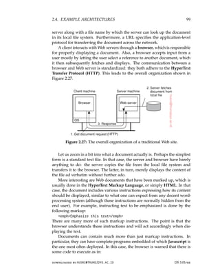
![100 CHAPTER 2. ARCHITECTURES
script type=’’text/javascript’’..../script
and as long as the browser as an appropriate embedded interpreter for the
specified language, everything between “script” and “/script” will be
executed as any other other program. The main benefit of including scripts
is that it allows for much better interaction with the end user, including
sending information back to the server. (The latter, by the way, has always
been supported in HTML through forms.)
Much more can be said about Web documents, but this is not the place to
do so. A good introduction on how to build Web-based applications can be
found in [Sebesta, 2006].
Multitiered architectures
The Web started out as the relatively simple two-tiered client-server system
shown in Figure 2.27. By now, this simple architecture has been extended to
support much more sophisticated means of documents. In fact, one could
justafiably argue that the term “document” is no longer appropriate. For
one, most things that we get to see in our browser has been generated on the
spot as the result of sending a request to a Web server. Content is stored in
a database at the server’s side, along with client-side scripts and such, to be
composed on-the-fly into a document which is then subsequently sent to the
client’s browser. Documents have thus become completely dynamic.
One of the first enhancements to the basic architecture was support for
simple user interaction by means of the Common Gateway Interface or sim-
ply CGI. CGI defines a standard way by which a Web server can execute a
program taking user data as input. Usually, user data come from an HTML
form; it specifies the program that is to be executed at the server side, along
with parameter values that are filled in by the user. Once the form has been
completed, the program’s name and collected parameter values are sent to
the server, as shown in Figure 2.28.
Figure 2.28: The principle of using server-side CGI programs.
When the server sees the request, it starts the program named in the
request and passes it the parameter values. At that point, the program simply
DS 3.01pre downloaded by HUSNI@TRUNOJOYO.AC.ID
100 CHAPTER 2. ARCHITECTURES
script type=’’text/javascript’’..../script
and as long as the browser as an appropriate embedded interpreter for the
specified language, everything between “script” and “/script” will be
executed as any other other program. The main benefit of including scripts
is that it allows for much better interaction with the end user, including
sending information back to the server. (The latter, by the way, has always
been supported in HTML through forms.)
Much more can be said about Web documents, but this is not the place to
do so. A good introduction on how to build Web-based applications can be
found in [Sebesta, 2006].
Multitiered architectures
The Web started out as the relatively simple two-tiered client-server system
shown in Figure 2.27. By now, this simple architecture has been extended to
support much more sophisticated means of documents. In fact, one could
justafiably argue that the term “document” is no longer appropriate. For
one, most things that we get to see in our browser has been generated on the
spot as the result of sending a request to a Web server. Content is stored in
a database at the server’s side, along with client-side scripts and such, to be
composed on-the-fly into a document which is then subsequently sent to the
client’s browser. Documents have thus become completely dynamic.
One of the first enhancements to the basic architecture was support for
simple user interaction by means of the Common Gateway Interface or sim-
ply CGI. CGI defines a standard way by which a Web server can execute a
program taking user data as input. Usually, user data come from an HTML
form; it specifies the program that is to be executed at the server side, along
with parameter values that are filled in by the user. Once the form has been
completed, the program’s name and collected parameter values are sent to
the server, as shown in Figure 2.28.
Figure 2.28: The principle of using server-side CGI programs.
When the server sees the request, it starts the program named in the
request and passes it the parameter values. At that point, the program simply
DS 3.01pre downloaded by HUSNI@TRUNOJOYO.AC.ID](https://image.slidesharecdn.com/distributed-systems-3rd-edition-251215232331-7e034da0/85/architectureec-distributed-systems-3rd-Edition-pdf-114-320.jpg)
![2.5. SUMMARY 101
does its work and generally returns the results in the form of a document that
is sent back to the user’s browser to be displayed.
CGI programs can be as sophisticated as a developer wants. For example,
as shown in Figure 2.28 many programs operate on a database local to the
Web server. After processing the data, the program generates an HTML
document and returns that document to the server. The server will then pass
the document to the client. An interesting observation is that to the server,
it appears as if it is asking the CGI program to fetch a document. In other
words, the server does nothing but delegate the fetching of a document to an
external program.
The main task of a server used to be handling client requests by simply
fetching documents. With CGI programs, fetching a document could be
delegated in such a way that the server would remain unaware of whether
a document had been generated on the fly, or actually read from the local
file system. Note that we have just described a two-tiered organization of
server-side software.
However, servers nowadays do much more than just fetching documents.
One of the most important enhancements is that servers can also process a
document before passing it to the client. In particular, a document may contain
a server-side script, which is executed by the server when the document has
been fetched locally. The result of executing a script is sent along with the
rest of the document to the client. The script itself is not sent. In other words,
using a server-side script changes a document by essentially replacing the
script with the results of its execution. To make matters concrete, take a look
at a very simple example of dynamically generating a document. Assume a
file is stored at the server with the following content:
strong ?php echo $_SERVER[’REMOTE_ADDR’]; ? /strong
The server will examine the file and subsequently process the PHP code (be-
tween “?php” and “?”) replacing the code with the address of the requesting
client. Much more sophisticated settings are possible, such as accessing a
local database and subsequently fetching content from that database to be
combined with other dynamically generated content.
2.5 Summary
Distributed systems can be organized in many different ways. We can make
a distinction between software architecture and system architecture. The
latter considers where the components that constitute a distributed system
are placed across the various machines. The former is more concerned about
the logical organization of the software: how do components interact, in what
ways can they be structured, how can they be made independent, and so on.
A keyword when talking about architectures is architectural style. A
style reflects the basic principle that is followed in organizing the interaction
downloaded by HUSNI@TRUNOJOYO.AC.ID DS 3.01pre
2.5. SUMMARY 101
does its work and generally returns the results in the form of a document that
is sent back to the user’s browser to be displayed.
CGI programs can be as sophisticated as a developer wants. For example,
as shown in Figure 2.28 many programs operate on a database local to the
Web server. After processing the data, the program generates an HTML
document and returns that document to the server. The server will then pass
the document to the client. An interesting observation is that to the server,
it appears as if it is asking the CGI program to fetch a document. In other
words, the server does nothing but delegate the fetching of a document to an
external program.
The main task of a server used to be handling client requests by simply
fetching documents. With CGI programs, fetching a document could be
delegated in such a way that the server would remain unaware of whether
a document had been generated on the fly, or actually read from the local
file system. Note that we have just described a two-tiered organization of
server-side software.
However, servers nowadays do much more than just fetching documents.
One of the most important enhancements is that servers can also process a
document before passing it to the client. In particular, a document may contain
a server-side script, which is executed by the server when the document has
been fetched locally. The result of executing a script is sent along with the
rest of the document to the client. The script itself is not sent. In other words,
using a server-side script changes a document by essentially replacing the
script with the results of its execution. To make matters concrete, take a look
at a very simple example of dynamically generating a document. Assume a
file is stored at the server with the following content:
strong ?php echo $_SERVER[’REMOTE_ADDR’]; ? /strong
The server will examine the file and subsequently process the PHP code (be-
tween “?php” and “?”) replacing the code with the address of the requesting
client. Much more sophisticated settings are possible, such as accessing a
local database and subsequently fetching content from that database to be
combined with other dynamically generated content.
2.5 Summary
Distributed systems can be organized in many different ways. We can make
a distinction between software architecture and system architecture. The
latter considers where the components that constitute a distributed system
are placed across the various machines. The former is more concerned about
the logical organization of the software: how do components interact, in what
ways can they be structured, how can they be made independent, and so on.
A keyword when talking about architectures is architectural style. A
style reflects the basic principle that is followed in organizing the interaction
downloaded by HUSNI@TRUNOJOYO.AC.ID DS 3.01pre](https://image.slidesharecdn.com/distributed-systems-3rd-edition-251215232331-7e034da0/85/architectureec-distributed-systems-3rd-Edition-pdf-115-320.jpg)
![104 CHAPTER 3. PROCESSES
achieve this perspective, including wide-area servers like PlanetLab.
An important issue, especially in wide-area distributed systems, is moving
processes between different machines. Process migration or more specifically,
code migration, can help in achieving scalability, but can also help to dynami-
cally configure clients and servers. What is actually meant by code migration
and what its implications are is also discussed in this chapter.
3.1 Threads
Although processes form a building block in distributed systems, practice
indicates that the granularity of processes as provided by the operating
systems on which distributed systems are built is not sufficient. Instead, it
turns out that having a finer granularity in the form of multiple threads of
control per process makes it much easier to build distributed applications
and to get better performance. In this section, we take a closer look at the
role of threads in distributed systems and explain why they are so important.
More on threads and how they can be used to build applications can be found
in [Lewis and Berg, 1998; Stevens, 1999; Robbins and Robbins, 2003]. Herlihy
and Shavit [2008] is highly recommended to learn more about multithreaded
concurrent programming in general.
Introduction to threads
To understand the role of threads in distributed systems, it is important to un-
derstand what a process is, and how processes and threads relate. To execute
a program, an operating system creates a number of virtual processors, each
one for running a different program. To keep track of these virtual processors,
the operating system has a process table, containing entries to store CPU
register values, memory maps, open files, accounting information, privileges,
etc. Jointly, these entries form a process context.
A process context can be viewed as the software analog of the hardware’s
processor context. The latter consists of the minimal information that is
automatically stored by the hardware to handle an interrupt, and to later
return to where the CPU left off. The processor context contains at least the
program counter, but sometimes also other register values such as the stack
pointer.
A process is often defined as a program in execution, that is, a program
that is currently being executed on one of the operating system’s virtual
processors. An important issue is that the operating system takes great care
to ensure that independent processes cannot maliciously or inadvertently
affect the correctness of each other’s behavior. In other words, the fact
that multiple processes may be concurrently sharing the same CPU and
other hardware resources is made transparent. Usually, the operating system
requires hardware support to enforce this separation.
DS 3.01pre downloaded by HUSNI@TRUNOJOYO.AC.ID
104 CHAPTER 3. PROCESSES
achieve this perspective, including wide-area servers like PlanetLab.
An important issue, especially in wide-area distributed systems, is moving
processes between different machines. Process migration or more specifically,
code migration, can help in achieving scalability, but can also help to dynami-
cally configure clients and servers. What is actually meant by code migration
and what its implications are is also discussed in this chapter.
3.1 Threads
Although processes form a building block in distributed systems, practice
indicates that the granularity of processes as provided by the operating
systems on which distributed systems are built is not sufficient. Instead, it
turns out that having a finer granularity in the form of multiple threads of
control per process makes it much easier to build distributed applications
and to get better performance. In this section, we take a closer look at the
role of threads in distributed systems and explain why they are so important.
More on threads and how they can be used to build applications can be found
in [Lewis and Berg, 1998; Stevens, 1999; Robbins and Robbins, 2003]. Herlihy
and Shavit [2008] is highly recommended to learn more about multithreaded
concurrent programming in general.
Introduction to threads
To understand the role of threads in distributed systems, it is important to un-
derstand what a process is, and how processes and threads relate. To execute
a program, an operating system creates a number of virtual processors, each
one for running a different program. To keep track of these virtual processors,
the operating system has a process table, containing entries to store CPU
register values, memory maps, open files, accounting information, privileges,
etc. Jointly, these entries form a process context.
A process context can be viewed as the software analog of the hardware’s
processor context. The latter consists of the minimal information that is
automatically stored by the hardware to handle an interrupt, and to later
return to where the CPU left off. The processor context contains at least the
program counter, but sometimes also other register values such as the stack
pointer.
A process is often defined as a program in execution, that is, a program
that is currently being executed on one of the operating system’s virtual
processors. An important issue is that the operating system takes great care
to ensure that independent processes cannot maliciously or inadvertently
affect the correctness of each other’s behavior. In other words, the fact
that multiple processes may be concurrently sharing the same CPU and
other hardware resources is made transparent. Usually, the operating system
requires hardware support to enforce this separation.
DS 3.01pre downloaded by HUSNI@TRUNOJOYO.AC.ID](https://image.slidesharecdn.com/distributed-systems-3rd-edition-251215232331-7e034da0/85/architectureec-distributed-systems-3rd-Edition-pdf-118-320.jpg)
![106 CHAPTER 3. PROCESSES
The most important benefit comes from the fact that in a single-threaded
process, whenever a blocking system call is executed, the process as a whole is
blocked. To illustrate, consider an application such as a spreadsheet program,
and assume that a user continuously and interactively wants to change values.
An important property of a spreadsheet program is that it maintains the func-
tional dependencies between different cells, often from different spreadsheets.
Therefore, whenever a cell is modified, all dependent cells are automatically
updated. When a user changes the value in a single cell, such a modification
can trigger a large series of computations. If there is only a single thread
of control, computation cannot proceed while the program is waiting for
input. Likewise, it is not easy to provide input while dependencies are being
calculated. The easy solution is to have at least two threads of control: one for
handling interaction with the user and one for updating the spreadsheet. In
the meantime, a third thread could be used for backing up the spreadsheet to
disk while the other two are doing their work.
Another advantage of multithreading is that it becomes possible to exploit
parallelism when executing the program on a multiprocessor or multicore
system. In that case, each thread is assigned to a different CPU or core while
shared data are stored in shared main memory. When properly designed,
such parallelism can be transparent: the process will run equally well on a
uniprocessor system, albeit slower. Multithreading for parallelism is becoming
increasingly important with the availability of relatively cheap multiprocessor
and multicore computers. Such computer systems are typically used for
running servers in client-server applications, but are by now also extensively
used in devices such as smartphones.
Multithreading is also useful in the context of large applications. Such
applications are often developed as a collection of cooperating programs,
each to be executed by a separate process. This approach is typical for a
Unix environment. Cooperation between programs is implemented by means
of interprocess communication (IPC) mechanisms. For Unix systems, these
mechanisms typically include (named) pipes, message queues, and shared
memory segments (see also Stevens and Rago [2005]). The major drawback of
all IPC mechanisms is that communication often requires relatively extensive
context switching, shown at three different points in Figure 3.1.
Because IPC requires kernel intervention, a process will generally first
have to switch from user mode to kernel mode, shown as S1 in Figure 3.1.
This requires changing the memory map in the MMU, as well as flushing the
TLB. Within the kernel, a process context switch takes place (S2 in the figure),
after which the other party can be activated by switching from kernel mode to
user mode again (S3 in Figure 3.1). The latter switch again requires changing
the MMU map and flushing the TLB.
Instead of using processes, an application can also be constructed such
that different parts are executed by separate threads. Communication between
DS 3.01pre downloaded by HUSNI@TRUNOJOYO.AC.ID
106 CHAPTER 3. PROCESSES
The most important benefit comes from the fact that in a single-threaded
process, whenever a blocking system call is executed, the process as a whole is
blocked. To illustrate, consider an application such as a spreadsheet program,
and assume that a user continuously and interactively wants to change values.
An important property of a spreadsheet program is that it maintains the func-
tional dependencies between different cells, often from different spreadsheets.
Therefore, whenever a cell is modified, all dependent cells are automatically
updated. When a user changes the value in a single cell, such a modification
can trigger a large series of computations. If there is only a single thread
of control, computation cannot proceed while the program is waiting for
input. Likewise, it is not easy to provide input while dependencies are being
calculated. The easy solution is to have at least two threads of control: one for
handling interaction with the user and one for updating the spreadsheet. In
the meantime, a third thread could be used for backing up the spreadsheet to
disk while the other two are doing their work.
Another advantage of multithreading is that it becomes possible to exploit
parallelism when executing the program on a multiprocessor or multicore
system. In that case, each thread is assigned to a different CPU or core while
shared data are stored in shared main memory. When properly designed,
such parallelism can be transparent: the process will run equally well on a
uniprocessor system, albeit slower. Multithreading for parallelism is becoming
increasingly important with the availability of relatively cheap multiprocessor
and multicore computers. Such computer systems are typically used for
running servers in client-server applications, but are by now also extensively
used in devices such as smartphones.
Multithreading is also useful in the context of large applications. Such
applications are often developed as a collection of cooperating programs,
each to be executed by a separate process. This approach is typical for a
Unix environment. Cooperation between programs is implemented by means
of interprocess communication (IPC) mechanisms. For Unix systems, these
mechanisms typically include (named) pipes, message queues, and shared
memory segments (see also Stevens and Rago [2005]). The major drawback of
all IPC mechanisms is that communication often requires relatively extensive
context switching, shown at three different points in Figure 3.1.
Because IPC requires kernel intervention, a process will generally first
have to switch from user mode to kernel mode, shown as S1 in Figure 3.1.
This requires changing the memory map in the MMU, as well as flushing the
TLB. Within the kernel, a process context switch takes place (S2 in the figure),
after which the other party can be activated by switching from kernel mode to
user mode again (S3 in Figure 3.1). The latter switch again requires changing
the MMU map and flushing the TLB.
Instead of using processes, an application can also be constructed such
that different parts are executed by separate threads. Communication between
DS 3.01pre downloaded by HUSNI@TRUNOJOYO.AC.ID](https://image.slidesharecdn.com/distributed-systems-3rd-edition-251215232331-7e034da0/85/architectureec-distributed-systems-3rd-Edition-pdf-120-320.jpg)
![3.1. THREADS 107
Figure 3.1: Context switching as the result of IPC.
those parts is entirely dealt with by using shared data. Thread switching can
sometimes be done entirely in user space, although in other implementations,
the kernel is aware of threads and schedules them. The effect can be a dramatic
improvement in performance.
Finally, there is also a pure software engineering reason to use threads:
many applications are simply easier to structure as a collection of cooperating
threads. Think of applications that need to perform several (more or less
independent) tasks, like our spreadsheet example discussed previously.
Note 3.1 (Advanced: The cost of a context switch)
There have been many studies on measuring the performance effects of context
switches. As in so many cases with measuring computer systems, finding the
ground truth is not easy. Tsafrir [2007] notes that handling clock ticks has become
more or less ubiquitous in operating systems, making it an excellent candidate
to measure overheads. A clock handler is activated once every T milliseconds
by means of a clock interrupt. Common values for T range between 0.5 and
20 milliseconds, corresponding to interrupt frequencies of 2000 Hz and 50 Hz,
respectively. The handler typically assists in realizing various timing and CPU
usage services, sends alarm signals, and assists in preempting running tasks
for fair CPU sharing. By simply varying the frequency by which the hardware
generates an interrupt, one can easily get an impression of the incurred overhead.
To measure the performance effects of an interrupt, a distinction is made
between direct overhead and indirect overhead. The direct overhead consists of
the time it takes to do the actual context switch along with the time it takes for
the handler to do its work and subsequently switching back to the interrupted
task. The indirect overhead is everything else, and is mainly caused by cache
perturbations (to which we will return shortly). For various Intel processors,
Tsafrir [2007] found that the time to switch context is in the order of 0.5–1
microsecond, and that the handler itself takes in the order of 0.5–7 microseconds
to do its work, depending strongly on the implementation.
downloaded by HUSNI@TRUNOJOYO.AC.ID DS 3.01pre
3.1. THREADS 107
Figure 3.1: Context switching as the result of IPC.
those parts is entirely dealt with by using shared data. Thread switching can
sometimes be done entirely in user space, although in other implementations,
the kernel is aware of threads and schedules them. The effect can be a dramatic
improvement in performance.
Finally, there is also a pure software engineering reason to use threads:
many applications are simply easier to structure as a collection of cooperating
threads. Think of applications that need to perform several (more or less
independent) tasks, like our spreadsheet example discussed previously.
Note 3.1 (Advanced: The cost of a context switch)
There have been many studies on measuring the performance effects of context
switches. As in so many cases with measuring computer systems, finding the
ground truth is not easy. Tsafrir [2007] notes that handling clock ticks has become
more or less ubiquitous in operating systems, making it an excellent candidate
to measure overheads. A clock handler is activated once every T milliseconds
by means of a clock interrupt. Common values for T range between 0.5 and
20 milliseconds, corresponding to interrupt frequencies of 2000 Hz and 50 Hz,
respectively. The handler typically assists in realizing various timing and CPU
usage services, sends alarm signals, and assists in preempting running tasks
for fair CPU sharing. By simply varying the frequency by which the hardware
generates an interrupt, one can easily get an impression of the incurred overhead.
To measure the performance effects of an interrupt, a distinction is made
between direct overhead and indirect overhead. The direct overhead consists of
the time it takes to do the actual context switch along with the time it takes for
the handler to do its work and subsequently switching back to the interrupted
task. The indirect overhead is everything else, and is mainly caused by cache
perturbations (to which we will return shortly). For various Intel processors,
Tsafrir [2007] found that the time to switch context is in the order of 0.5–1
microsecond, and that the handler itself takes in the order of 0.5–7 microseconds
to do its work, depending strongly on the implementation.
downloaded by HUSNI@TRUNOJOYO.AC.ID DS 3.01pre](https://image.slidesharecdn.com/distributed-systems-3rd-edition-251215232331-7e034da0/85/architectureec-distributed-systems-3rd-Edition-pdf-121-320.jpg)
![108 CHAPTER 3. PROCESSES
However, it turns out that the direct overhead is not really that influential. In
a complimentary study, Liu and Solihin [2010] make clear that context switching
can greatly perturbate the cache resulting in a loss of performance in comparison
to the situation before an interrupt occurred. In fact, for the simple case of clock
interrupts, Tsafrir [2007] measured an indirect overhead of approximately 80%.
To understand what is going on, consider the data organizations as sketched in
Figure 3.2. Assume the cache is organized such that a least-recently used block of
data is removed from the cache when room is needed for a fresh data block.
(a) (b) (c)
Figure 3.2: The organization of the cache when dealing with interrupts:
(a) before the context switch, (b) after the context switch, and (c) after
accessing block D. (Adapted from [Liu and Solihin, 2010].)
Figure 3.2(a) shows the situation before the interrupt occurs. After the inter-
rupt has been handled, block D may have been evicted from the cache, leaving a
hole as shown in Figure 3.2(b). Accessing block D will copy it back into the cache,
possibly evicting block C, and so on. In other words, even a simple interrupt may
cause a considerable, and relatively long-lasting reorganization of the cache, in
turn, affecting the overall performance of an application.
Thread implementation
Threads are often provided in the form of a thread package. Such a package
contains operations to create and destroy threads as well as operations on
synchronization variables such as mutexes and condition variables. There are
basically two approaches to implement a thread package. The first approach
is to construct a thread library that is executed entirely in user space. The
second approach is to have the kernel be aware of threads and schedule them.
A user-level thread library has a number of advantages. First, it is cheap
to create and destroy threads. Because all thread administration is kept in the
user’s address space, the price of creating a thread is primarily determined
by the cost for allocating memory to set up a thread stack. Analogously,
destroying a thread mainly involves freeing memory for the stack, which is
no longer used. Both operations are cheap.
A second advantage of user-level threads is that switching thread context
can often be done in just a few instructions. Basically, only the values of
the CPU registers need to be stored and subsequently reloaded with the
previously stored values of the thread to which it is being switched. There is
DS 3.01pre downloaded by HUSNI@TRUNOJOYO.AC.ID
108 CHAPTER 3. PROCESSES
However, it turns out that the direct overhead is not really that influential. In
a complimentary study, Liu and Solihin [2010] make clear that context switching
can greatly perturbate the cache resulting in a loss of performance in comparison
to the situation before an interrupt occurred. In fact, for the simple case of clock
interrupts, Tsafrir [2007] measured an indirect overhead of approximately 80%.
To understand what is going on, consider the data organizations as sketched in
Figure 3.2. Assume the cache is organized such that a least-recently used block of
data is removed from the cache when room is needed for a fresh data block.
(a) (b) (c)
Figure 3.2: The organization of the cache when dealing with interrupts:
(a) before the context switch, (b) after the context switch, and (c) after
accessing block D. (Adapted from [Liu and Solihin, 2010].)
Figure 3.2(a) shows the situation before the interrupt occurs. After the inter-
rupt has been handled, block D may have been evicted from the cache, leaving a
hole as shown in Figure 3.2(b). Accessing block D will copy it back into the cache,
possibly evicting block C, and so on. In other words, even a simple interrupt may
cause a considerable, and relatively long-lasting reorganization of the cache, in
turn, affecting the overall performance of an application.
Thread implementation
Threads are often provided in the form of a thread package. Such a package
contains operations to create and destroy threads as well as operations on
synchronization variables such as mutexes and condition variables. There are
basically two approaches to implement a thread package. The first approach
is to construct a thread library that is executed entirely in user space. The
second approach is to have the kernel be aware of threads and schedule them.
A user-level thread library has a number of advantages. First, it is cheap
to create and destroy threads. Because all thread administration is kept in the
user’s address space, the price of creating a thread is primarily determined
by the cost for allocating memory to set up a thread stack. Analogously,
destroying a thread mainly involves freeing memory for the stack, which is
no longer used. Both operations are cheap.
A second advantage of user-level threads is that switching thread context
can often be done in just a few instructions. Basically, only the values of
the CPU registers need to be stored and subsequently reloaded with the
previously stored values of the thread to which it is being switched. There is
DS 3.01pre downloaded by HUSNI@TRUNOJOYO.AC.ID](https://image.slidesharecdn.com/distributed-systems-3rd-edition-251215232331-7e034da0/85/architectureec-distributed-systems-3rd-Edition-pdf-122-320.jpg)
![110 CHAPTER 3. PROCESSES
and is instructed to execute the scheduling routine in search of a thread to execute.
If there are several LWPs, then each of them executes the scheduler. The thread
table, which is used to keep track of the current set of threads, is thus shared by
the LWPs. Protecting this table to guarantee mutually exclusive access is done by
means of mutexes that are implemented entirely in user space. In other words,
synchronization between LWPs does not require any kernel support.
Figure 3.3: Combining kernel-level processes and user-level threads.
When an LWP finds a runnable thread, it switches context to that thread.
Meanwhile, other LWPs may be looking for other runnable threads as well. If a
thread needs to block on a mutex or condition variable, it does the necessary ad-
ministration and eventually calls the scheduling routine. When another runnable
thread has been found, a context switch is made to that thread. The beauty of all
this is that the LWP executing the thread need not be informed: the context switch
is implemented completely in user space and appears to the LWP as normal
program code.
Now let us see what happens when a thread does a blocking system call. In
that case, execution changes from user mode to kernel mode, but still continues
in the context of the current LWP. At the point where the current LWP can no
longer continue, the operating system may decide to switch context to another
LWP, which also implies that a context switch is made back to user mode. The
selected LWP will simply continue where it had previously left off.
There are several advantages to using LWPs in combination with a user-
level thread package. First, creating, destroying, and synchronizing threads is
relatively cheap and involves no kernel intervention at all. Second, provided
that a process has enough LWPs, a blocking system call will not suspend the
entire process. Third, there is no need for an application to know about the
LWPs. All it sees are user-level threads. Fourth, LWPs can be easily used in
multiprocessing environments by executing different LWPs on different CPUs.
This multiprocessing can be hidden entirely from the application. The only
drawback of lightweight processes in combination with user-level threads is that
we still need to create and destroy LWPs, which is just as expensive as with
kernel-level threads. However, creating and destroying LWPs needs to be done
only occasionally, and is often fully controlled by the operating system.
An alternative, but similar approach to lightweight processes, is to make use
of scheduler activations [Anderson et al., 1991]. The most essential difference
DS 3.01pre downloaded by HUSNI@TRUNOJOYO.AC.ID
110 CHAPTER 3. PROCESSES
and is instructed to execute the scheduling routine in search of a thread to execute.
If there are several LWPs, then each of them executes the scheduler. The thread
table, which is used to keep track of the current set of threads, is thus shared by
the LWPs. Protecting this table to guarantee mutually exclusive access is done by
means of mutexes that are implemented entirely in user space. In other words,
synchronization between LWPs does not require any kernel support.
Figure 3.3: Combining kernel-level processes and user-level threads.
When an LWP finds a runnable thread, it switches context to that thread.
Meanwhile, other LWPs may be looking for other runnable threads as well. If a
thread needs to block on a mutex or condition variable, it does the necessary ad-
ministration and eventually calls the scheduling routine. When another runnable
thread has been found, a context switch is made to that thread. The beauty of all
this is that the LWP executing the thread need not be informed: the context switch
is implemented completely in user space and appears to the LWP as normal
program code.
Now let us see what happens when a thread does a blocking system call. In
that case, execution changes from user mode to kernel mode, but still continues
in the context of the current LWP. At the point where the current LWP can no
longer continue, the operating system may decide to switch context to another
LWP, which also implies that a context switch is made back to user mode. The
selected LWP will simply continue where it had previously left off.
There are several advantages to using LWPs in combination with a user-
level thread package. First, creating, destroying, and synchronizing threads is
relatively cheap and involves no kernel intervention at all. Second, provided
that a process has enough LWPs, a blocking system call will not suspend the
entire process. Third, there is no need for an application to know about the
LWPs. All it sees are user-level threads. Fourth, LWPs can be easily used in
multiprocessing environments by executing different LWPs on different CPUs.
This multiprocessing can be hidden entirely from the application. The only
drawback of lightweight processes in combination with user-level threads is that
we still need to create and destroy LWPs, which is just as expensive as with
kernel-level threads. However, creating and destroying LWPs needs to be done
only occasionally, and is often fully controlled by the operating system.
An alternative, but similar approach to lightweight processes, is to make use
of scheduler activations [Anderson et al., 1991]. The most essential difference
DS 3.01pre downloaded by HUSNI@TRUNOJOYO.AC.ID](https://image.slidesharecdn.com/distributed-systems-3rd-edition-251215232331-7e034da0/85/architectureec-distributed-systems-3rd-Edition-pdf-124-320.jpg)
![3.1. THREADS 111
between scheduler activations and LWPs is that when a thread blocks on a
system call, the kernel does an upcall to the thread package, effectively calling
the scheduler routine to select the next runnable thread. The same procedure
is repeated when a thread is unblocked. The advantage of this approach is that
it saves management of LWPs by the kernel. However, the use of upcalls is
considered less elegant, as it violates the structure of layered systems, in which
calls only to the next lower-level layer are permitted.
Because of the intricacies involved in deploying a many-to-many threading
model, and the relatively low performance gain (which is now understood to be
dominated by caching behavior), the simple one-to-one threading model is often
preferred.
As a final note, it is important to realize that using threads is one way
of organizing simultaneous and concurrent executions within an application.
In practice, we often see that applications are constructed as a collection of
concurrent processes, jointly making use of the interprocess facilities offered by
an operating system (see also [Robbins and Robbins, 2003; Stevens, 1999]). A
good example of this approach is the organization of the Apache Web server,
which, by default, starts with a handful of processes for handling incoming
requests. Each process forms a single-threaded instantiation of the server,
yet is capable of communicating with other instances through fairly standard
means.
As argued by Srinivasan [2010], using processes instead of threads has
the important advantage of separating the data space: each process works on
its own part of data and is protected from interference from others through
the operating system. The advantage of this separation should not be un-
derestimated: thread programming is considered to be notoriously difficult
because the developer is fully responsible for managing concurrent access
to shared data. Using processes, data spaces, in the end, are protected by
hardware support. If a process attempts to access data outside its allocated
memory, the hardware will raise an exception, which is then further processed
by the operating system. No such support is available for threads concurrently
operating within the same process.
Threads in distributed systems
An important property of threads is that they can provide a convenient means
of allowing blocking system calls without blocking the entire process in which
the thread is running. This property makes threads particularly attractive to
use in distributed systems as it makes it much easier to express communication
in the form of maintaining multiple logical connections at the same time. We
illustrate this point by taking a closer look at multithreaded clients and servers,
respectively.
downloaded by HUSNI@TRUNOJOYO.AC.ID DS 3.01pre
3.1. THREADS 111
between scheduler activations and LWPs is that when a thread blocks on a
system call, the kernel does an upcall to the thread package, effectively calling
the scheduler routine to select the next runnable thread. The same procedure
is repeated when a thread is unblocked. The advantage of this approach is that
it saves management of LWPs by the kernel. However, the use of upcalls is
considered less elegant, as it violates the structure of layered systems, in which
calls only to the next lower-level layer are permitted.
Because of the intricacies involved in deploying a many-to-many threading
model, and the relatively low performance gain (which is now understood to be
dominated by caching behavior), the simple one-to-one threading model is often
preferred.
As a final note, it is important to realize that using threads is one way
of organizing simultaneous and concurrent executions within an application.
In practice, we often see that applications are constructed as a collection of
concurrent processes, jointly making use of the interprocess facilities offered by
an operating system (see also [Robbins and Robbins, 2003; Stevens, 1999]). A
good example of this approach is the organization of the Apache Web server,
which, by default, starts with a handful of processes for handling incoming
requests. Each process forms a single-threaded instantiation of the server,
yet is capable of communicating with other instances through fairly standard
means.
As argued by Srinivasan [2010], using processes instead of threads has
the important advantage of separating the data space: each process works on
its own part of data and is protected from interference from others through
the operating system. The advantage of this separation should not be un-
derestimated: thread programming is considered to be notoriously difficult
because the developer is fully responsible for managing concurrent access
to shared data. Using processes, data spaces, in the end, are protected by
hardware support. If a process attempts to access data outside its allocated
memory, the hardware will raise an exception, which is then further processed
by the operating system. No such support is available for threads concurrently
operating within the same process.
Threads in distributed systems
An important property of threads is that they can provide a convenient means
of allowing blocking system calls without blocking the entire process in which
the thread is running. This property makes threads particularly attractive to
use in distributed systems as it makes it much easier to express communication
in the form of maintaining multiple logical connections at the same time. We
illustrate this point by taking a closer look at multithreaded clients and servers,
respectively.
downloaded by HUSNI@TRUNOJOYO.AC.ID DS 3.01pre](https://image.slidesharecdn.com/distributed-systems-3rd-edition-251215232331-7e034da0/85/architectureec-distributed-systems-3rd-Edition-pdf-125-320.jpg)
![112 CHAPTER 3. PROCESSES
Multithreaded clients
To establish a high degree of distribution transparency, distributed systems
that operate in wide-area networks may need to conceal long interprocess
message propagation times. The round-trip delay in a wide-area network can
easily be in the order of hundreds of milliseconds, or sometimes even seconds.
The usual way to hide communication latencies is to initiate communica-
tion and immediately proceed with something else. A typical example where
this happens is in Web browsers. In many cases, a Web document consists of
an HTML file containing plain text along with a collection of images, icons,
etc. To fetch each element of a Web document, the browser has to set up a
TCP/IP connection, read the incoming data, and pass it to a display compo-
nent. Setting up a connection as well as reading incoming data are inherently
blocking operations. When dealing with long-haul communication, we also
have the disadvantage that the time for each operation to complete may be
relatively long.
A Web browser often starts with fetching the HTML page and subsequently
displays it. To hide communication latencies as much as possible, some
browsers start displaying data while it is still coming in. While the text is
made available to the user, including the facilities for scrolling and such, the
browser continues with fetching other files that make up the page, such as
the images. The latter are displayed as they are brought in. The user need
thus not wait until all the components of the entire page are fetched before
the page is made available.
In effect, it is seen that the Web browser is doing a number of tasks
simultaneously. As it turns out, developing the browser as a multithreaded
client simplifies matters considerably. As soon as the main HTML file has
been fetched, separate threads can be activated to take care of fetching the
other parts. Each thread sets up a separate connection to the server and pulls
in the data. Setting up a connection and reading data from the server can
be programmed using the standard (blocking) system calls, assuming that
a blocking call does not suspend the entire process. As is also illustrated
in [Stevens, 1998], the code for each thread is the same and, above all, simple.
Meanwhile, the user notices only delays in the display of images and such,
but can otherwise browse through the document.
There is another important benefit to using multithreaded Web browsers
in which several connections can be opened simultaneously. In the previous
example, several connections were set up to the same server. If that server is
heavily loaded, or just plain slow, no real performance improvements will be
noticed compared to pulling in the files that make up the page strictly one
after the other.
However, in many cases, Web servers have been replicated across multiple
machines, where each server provides exactly the same set of Web documents.
The replicated servers are located at the same site, and are known under the
DS 3.01pre downloaded by HUSNI@TRUNOJOYO.AC.ID
112 CHAPTER 3. PROCESSES
Multithreaded clients
To establish a high degree of distribution transparency, distributed systems
that operate in wide-area networks may need to conceal long interprocess
message propagation times. The round-trip delay in a wide-area network can
easily be in the order of hundreds of milliseconds, or sometimes even seconds.
The usual way to hide communication latencies is to initiate communica-
tion and immediately proceed with something else. A typical example where
this happens is in Web browsers. In many cases, a Web document consists of
an HTML file containing plain text along with a collection of images, icons,
etc. To fetch each element of a Web document, the browser has to set up a
TCP/IP connection, read the incoming data, and pass it to a display compo-
nent. Setting up a connection as well as reading incoming data are inherently
blocking operations. When dealing with long-haul communication, we also
have the disadvantage that the time for each operation to complete may be
relatively long.
A Web browser often starts with fetching the HTML page and subsequently
displays it. To hide communication latencies as much as possible, some
browsers start displaying data while it is still coming in. While the text is
made available to the user, including the facilities for scrolling and such, the
browser continues with fetching other files that make up the page, such as
the images. The latter are displayed as they are brought in. The user need
thus not wait until all the components of the entire page are fetched before
the page is made available.
In effect, it is seen that the Web browser is doing a number of tasks
simultaneously. As it turns out, developing the browser as a multithreaded
client simplifies matters considerably. As soon as the main HTML file has
been fetched, separate threads can be activated to take care of fetching the
other parts. Each thread sets up a separate connection to the server and pulls
in the data. Setting up a connection and reading data from the server can
be programmed using the standard (blocking) system calls, assuming that
a blocking call does not suspend the entire process. As is also illustrated
in [Stevens, 1998], the code for each thread is the same and, above all, simple.
Meanwhile, the user notices only delays in the display of images and such,
but can otherwise browse through the document.
There is another important benefit to using multithreaded Web browsers
in which several connections can be opened simultaneously. In the previous
example, several connections were set up to the same server. If that server is
heavily loaded, or just plain slow, no real performance improvements will be
noticed compared to pulling in the files that make up the page strictly one
after the other.
However, in many cases, Web servers have been replicated across multiple
machines, where each server provides exactly the same set of Web documents.
The replicated servers are located at the same site, and are known under the
DS 3.01pre downloaded by HUSNI@TRUNOJOYO.AC.ID](https://image.slidesharecdn.com/distributed-systems-3rd-edition-251215232331-7e034da0/85/architectureec-distributed-systems-3rd-Edition-pdf-126-320.jpg)
![3.1. THREADS 113
same name. When a request for a Web page comes in, the request is forwarded
to one of the servers, often using a round-robin strategy or some other load-
balancing technique. When using a multithreaded client, connections may
be set up to different replicas, allowing data to be transferred in parallel,
effectively establishing that the entire Web document is fully displayed in a
much shorter time than with a nonreplicated server. This approach is possible
only if the client can handle truly parallel streams of incoming data. Threads
are ideal for this purpose.
Note 3.3 (Advanced: Exploiting client-side threads for performance)
Although there are obvious opportunities for using threads to reach high perfor-
mance, it is interesting to see whether multithreading is effectively exploited. In a
study to see to what extent multiple threads put a multicore processor to work,
Blake et al. [2010] looked at the execution of various applications on modern
architectures. Browsers, like many other client-side applications, are interactive
by nature for which reason the expected processor idle time may be quite high.
In order to properly measure to what extent a multicore processor is being used,
Blake et al. used a metric known as thread-level parallelism (TLP). Let ci denote
the fraction of time that exactly i threads are being executed simultaneously.
Thread-level parallelism is then defined as:
TLP =
∑N
i=1 i · ci
1 − c0
where N is the maximum number of threads that (can) execute at the same
time. In their study, a typical Web browser had a TLP value between 1.5 and 2.5,
meaning that in order to effectively exploit parallelism, the client machine should
have two or three cores, or likewise, 2–3 processors.
These results are interesting when considering that modern Web browsers
create hundreds of threads, and that tens of threads are active at the same time
(note that an active thread is not necessarily running; it may be blocked waiting for
an I/O request to complete). We thus see that multithreading is used to organize
an application, but that this multithreading is not leading to dramatic performance
improvements through hardware exploitation. That browsers can be effectively
designed for exploiting parallelism is shown, for example, by Meyerovich and
Bodik [2010]. By adapting existing algorithms, the authors manage to establish
several-fold speedups.
Multithreaded servers
Although there are important benefits to multithreaded clients, the main use
of multithreading in distributed systems is found at the server side. Practice
shows that multithreading not only simplifies server code considerably, but
also makes it much easier to develop servers that exploit parallelism to attain
high performance, even on uniprocessor systems. However, with modern
downloaded by HUSNI@TRUNOJOYO.AC.ID DS 3.01pre
3.1. THREADS 113
same name. When a request for a Web page comes in, the request is forwarded
to one of the servers, often using a round-robin strategy or some other load-
balancing technique. When using a multithreaded client, connections may
be set up to different replicas, allowing data to be transferred in parallel,
effectively establishing that the entire Web document is fully displayed in a
much shorter time than with a nonreplicated server. This approach is possible
only if the client can handle truly parallel streams of incoming data. Threads
are ideal for this purpose.
Note 3.3 (Advanced: Exploiting client-side threads for performance)
Although there are obvious opportunities for using threads to reach high perfor-
mance, it is interesting to see whether multithreading is effectively exploited. In a
study to see to what extent multiple threads put a multicore processor to work,
Blake et al. [2010] looked at the execution of various applications on modern
architectures. Browsers, like many other client-side applications, are interactive
by nature for which reason the expected processor idle time may be quite high.
In order to properly measure to what extent a multicore processor is being used,
Blake et al. used a metric known as thread-level parallelism (TLP). Let ci denote
the fraction of time that exactly i threads are being executed simultaneously.
Thread-level parallelism is then defined as:
TLP =
∑N
i=1 i · ci
1 − c0
where N is the maximum number of threads that (can) execute at the same
time. In their study, a typical Web browser had a TLP value between 1.5 and 2.5,
meaning that in order to effectively exploit parallelism, the client machine should
have two or three cores, or likewise, 2–3 processors.
These results are interesting when considering that modern Web browsers
create hundreds of threads, and that tens of threads are active at the same time
(note that an active thread is not necessarily running; it may be blocked waiting for
an I/O request to complete). We thus see that multithreading is used to organize
an application, but that this multithreading is not leading to dramatic performance
improvements through hardware exploitation. That browsers can be effectively
designed for exploiting parallelism is shown, for example, by Meyerovich and
Bodik [2010]. By adapting existing algorithms, the authors manage to establish
several-fold speedups.
Multithreaded servers
Although there are important benefits to multithreaded clients, the main use
of multithreading in distributed systems is found at the server side. Practice
shows that multithreading not only simplifies server code considerably, but
also makes it much easier to develop servers that exploit parallelism to attain
high performance, even on uniprocessor systems. However, with modern
downloaded by HUSNI@TRUNOJOYO.AC.ID DS 3.01pre](https://image.slidesharecdn.com/distributed-systems-3rd-edition-251215232331-7e034da0/85/architectureec-distributed-systems-3rd-Edition-pdf-127-320.jpg)
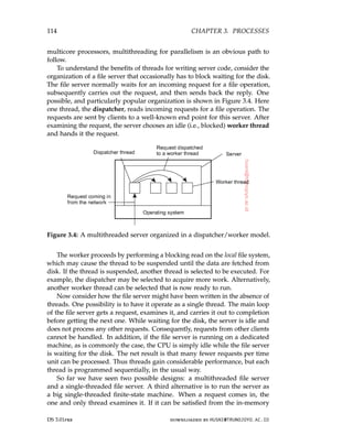
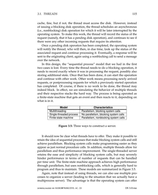
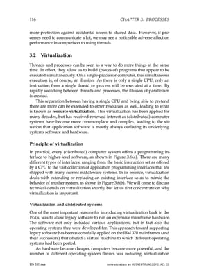
![3.2. VIRTUALIZATION 117
(a) (b)
Figure 3.6: (a) General organization between a program, interface, and system.
(b) General organization of virtualizing system A on top of B.
became less of an issue. However, matters have changed again since the
late 1990s. First, while hardware and low-level systems software change
reasonably fast, software at higher levels of abstraction (e.g., middleware and
applications), are often much more stable. In other words, we are facing
the situation that legacy software cannot be maintained in the same pace as
the platforms it relies on. Virtualization can help here by porting the legacy
interfaces to the new platforms and thus immediately opening up the latter
for large classes of existing programs.
Note 3.4 (Discussion: Stable software?)
Although there is indeed a lot of legacy software that can benefit from stable
interfaces to rapidly changing underlying hardware, it is a mistake to believe that
the software for widely available services hardly changes. With the increasing
shift toward server-side computing in the form of software-as-a-service (SaaS),
much software can be maintained for a relatively homogeneous platform, owned
entirely by the organization offering the associated service. As a consequence,
maintaining software products can be much easier, as there is much lesser need
to distribute changes to potentially millions of customers. In fact, changes may
rapidly succeed each other following changes in available hardware and platform,
but without any client actually noticing downtimes [Barroso and Hölze, 2009].
Equally important is the fact that networking has become completely
pervasive. It is hard to imagine that a modern computer is not connected to
a network. In practice, this connectivity requires that system administrators
maintain a large and heterogeneous collection of server computers, each
one running very different applications, which can be accessed by clients.
At the same time the various resources should be easily accessible to these
downloaded by HUSNI@TRUNOJOYO.AC.ID DS 3.01pre
3.2. VIRTUALIZATION 117
(a) (b)
Figure 3.6: (a) General organization between a program, interface, and system.
(b) General organization of virtualizing system A on top of B.
became less of an issue. However, matters have changed again since the
late 1990s. First, while hardware and low-level systems software change
reasonably fast, software at higher levels of abstraction (e.g., middleware and
applications), are often much more stable. In other words, we are facing
the situation that legacy software cannot be maintained in the same pace as
the platforms it relies on. Virtualization can help here by porting the legacy
interfaces to the new platforms and thus immediately opening up the latter
for large classes of existing programs.
Note 3.4 (Discussion: Stable software?)
Although there is indeed a lot of legacy software that can benefit from stable
interfaces to rapidly changing underlying hardware, it is a mistake to believe that
the software for widely available services hardly changes. With the increasing
shift toward server-side computing in the form of software-as-a-service (SaaS),
much software can be maintained for a relatively homogeneous platform, owned
entirely by the organization offering the associated service. As a consequence,
maintaining software products can be much easier, as there is much lesser need
to distribute changes to potentially millions of customers. In fact, changes may
rapidly succeed each other following changes in available hardware and platform,
but without any client actually noticing downtimes [Barroso and Hölze, 2009].
Equally important is the fact that networking has become completely
pervasive. It is hard to imagine that a modern computer is not connected to
a network. In practice, this connectivity requires that system administrators
maintain a large and heterogeneous collection of server computers, each
one running very different applications, which can be accessed by clients.
At the same time the various resources should be easily accessible to these
downloaded by HUSNI@TRUNOJOYO.AC.ID DS 3.01pre](https://image.slidesharecdn.com/distributed-systems-3rd-edition-251215232331-7e034da0/85/architectureec-distributed-systems-3rd-Edition-pdf-131-320.jpg)
![118 CHAPTER 3. PROCESSES
applications. Virtualization can help a lot: the diversity of platforms and
machines can be reduced by essentially letting each application run on its
own virtual machine, possibly including the related libraries and operating
system, which, in turn, run on a common platform.
This last type of virtualization provides a high degree of portability and
flexibility. For example, in order to realize content delivery networks that
can easily support replication of dynamic content, Awadallah and Rosenblum
[2002] have argued that management becomes much easier if edge servers
would support virtualization, allowing a complete site, including its environ-
ment to be dynamically copied. These arguments are still valid, and indeed,
portability is perhaps the most important reason why virtualization plays
such a key role in many distributed systems.
Types of virtualization
There are many different ways in which virtualization can be realized. An
overview of these various approaches is described by Smith and Nair [2005a].
To understand the differences in virtualization, it is important to realize that
computer systems generally offer four different types of interfaces, at three
different levels:
1. An interface between the hardware and software, referred to as the in-
struction set architecture (ISA), forming the set of machine instructions.
This set is divided into two subsets:
• Privileged instructions, which are allowed to be executed only by
the operating system.
• General instructions, which can be executed by any program.
2. An interface consisting of system calls as offered by an operating system.
3. An interface consisting of library calls, generally forming what is known
as an application programming interface (API). In many cases, the
aforementioned system calls are hidden by an API.
These different types are shown in Figure 3.7. The essence of virtualization is
to mimic the behavior of these interfaces.
Virtualization can take place in two different ways. First, we can build a
runtime system that essentially provides an abstract instruction set that is to
be used for executing applications. Instructions can be interpreted (as is the
case for the Java runtime environment), but could also be emulated as is done
for running Windows applications on Unix platforms. Note that in the latter
case, the emulator will also have to mimic the behavior of system calls, which
has proven to be generally far from trivial. This type of virtualization, shown
in Figure 3.8(a), leads to what Smith and Nair [2005a] call a process virtual
machine, stressing that virtualization is only for a single process.
DS 3.01pre downloaded by HUSNI@TRUNOJOYO.AC.ID
118 CHAPTER 3. PROCESSES
applications. Virtualization can help a lot: the diversity of platforms and
machines can be reduced by essentially letting each application run on its
own virtual machine, possibly including the related libraries and operating
system, which, in turn, run on a common platform.
This last type of virtualization provides a high degree of portability and
flexibility. For example, in order to realize content delivery networks that
can easily support replication of dynamic content, Awadallah and Rosenblum
[2002] have argued that management becomes much easier if edge servers
would support virtualization, allowing a complete site, including its environ-
ment to be dynamically copied. These arguments are still valid, and indeed,
portability is perhaps the most important reason why virtualization plays
such a key role in many distributed systems.
Types of virtualization
There are many different ways in which virtualization can be realized. An
overview of these various approaches is described by Smith and Nair [2005a].
To understand the differences in virtualization, it is important to realize that
computer systems generally offer four different types of interfaces, at three
different levels:
1. An interface between the hardware and software, referred to as the in-
struction set architecture (ISA), forming the set of machine instructions.
This set is divided into two subsets:
• Privileged instructions, which are allowed to be executed only by
the operating system.
• General instructions, which can be executed by any program.
2. An interface consisting of system calls as offered by an operating system.
3. An interface consisting of library calls, generally forming what is known
as an application programming interface (API). In many cases, the
aforementioned system calls are hidden by an API.
These different types are shown in Figure 3.7. The essence of virtualization is
to mimic the behavior of these interfaces.
Virtualization can take place in two different ways. First, we can build a
runtime system that essentially provides an abstract instruction set that is to
be used for executing applications. Instructions can be interpreted (as is the
case for the Java runtime environment), but could also be emulated as is done
for running Windows applications on Unix platforms. Note that in the latter
case, the emulator will also have to mimic the behavior of system calls, which
has proven to be generally far from trivial. This type of virtualization, shown
in Figure 3.8(a), leads to what Smith and Nair [2005a] call a process virtual
machine, stressing that virtualization is only for a single process.
DS 3.01pre downloaded by HUSNI@TRUNOJOYO.AC.ID](https://image.slidesharecdn.com/distributed-systems-3rd-edition-251215232331-7e034da0/85/architectureec-distributed-systems-3rd-Edition-pdf-132-320.jpg)
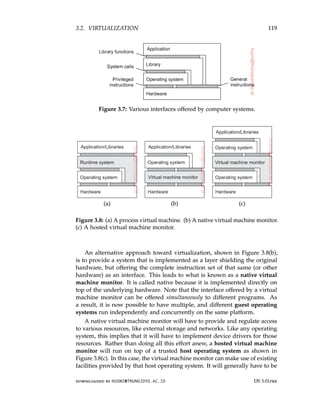
![120 CHAPTER 3. PROCESSES
given special privileges instead of running as a user-level application. Using
a hosted virtual machine monitor is highly popular in modern distributed
systems such as data centers and clouds.
As argued by Rosenblum and Garfinkel [2005], virtual machines are be-
coming increasingly important in the context of reliability and security for
(distributed) systems. As they allow for the isolation of a complete application
and its environment, a failure caused by an error or security attack need no
longer affect a complete machine. In addition, as we also mentioned before,
portability is greatly improved as virtual machines provide a further decou-
pling between hardware and software, allowing a complete environment to be
moved from one machine to another. We return to migration in Section 3.5.
Note 3.5 (Advanced: On the performance of virtual machines)
Virtual machines perform surprisingly well. In fact, many studies show that
modern virtual machines perform close to running applications directly on the
host operating system. Let us take a closer look at what is going under the hood
of virtual machines. A detailed and comprehensive account of virtual machines is
provided by Smith and Nair [2005b].
Figure 3.9: Applications, guest operating system, virtual machine monitor,
and host operating system on a single hardware platform.
Part of the answer to performance issue is shown in Figure 3.9, which forms
an extension of Figure 3.8(c): a large part of the code constituting a virtual
machine monitor, guest operating system, and application is running natively on
the underlying hardware. In particular, all general (i.e., unprivileged) machine
instructions are directly executed by the underlying machine instead of being
interpreted or emulated.
This approach is not new and is founded on research by Popek and Goldberg
[1974] who formalized the requirements for the efficient execution of virtual
machines. In a nutshell, Popek and Goldberg assumed that the underlying
machine provided at least two modes of operation (system and user mode), that
a subset of the instructions could be executed only in system mode, and that
memory addressing was relative (i.e., a physical address was obtained by adding
a relative address to an offset found in a relocation register). A distinction was
further made between two types of instructions. A privileged instruction is an
instruction that is characterized by the fact that if and only if executed in user
DS 3.01pre downloaded by HUSNI@TRUNOJOYO.AC.ID
120 CHAPTER 3. PROCESSES
given special privileges instead of running as a user-level application. Using
a hosted virtual machine monitor is highly popular in modern distributed
systems such as data centers and clouds.
As argued by Rosenblum and Garfinkel [2005], virtual machines are be-
coming increasingly important in the context of reliability and security for
(distributed) systems. As they allow for the isolation of a complete application
and its environment, a failure caused by an error or security attack need no
longer affect a complete machine. In addition, as we also mentioned before,
portability is greatly improved as virtual machines provide a further decou-
pling between hardware and software, allowing a complete environment to be
moved from one machine to another. We return to migration in Section 3.5.
Note 3.5 (Advanced: On the performance of virtual machines)
Virtual machines perform surprisingly well. In fact, many studies show that
modern virtual machines perform close to running applications directly on the
host operating system. Let us take a closer look at what is going under the hood
of virtual machines. A detailed and comprehensive account of virtual machines is
provided by Smith and Nair [2005b].
Figure 3.9: Applications, guest operating system, virtual machine monitor,
and host operating system on a single hardware platform.
Part of the answer to performance issue is shown in Figure 3.9, which forms
an extension of Figure 3.8(c): a large part of the code constituting a virtual
machine monitor, guest operating system, and application is running natively on
the underlying hardware. In particular, all general (i.e., unprivileged) machine
instructions are directly executed by the underlying machine instead of being
interpreted or emulated.
This approach is not new and is founded on research by Popek and Goldberg
[1974] who formalized the requirements for the efficient execution of virtual
machines. In a nutshell, Popek and Goldberg assumed that the underlying
machine provided at least two modes of operation (system and user mode), that
a subset of the instructions could be executed only in system mode, and that
memory addressing was relative (i.e., a physical address was obtained by adding
a relative address to an offset found in a relocation register). A distinction was
further made between two types of instructions. A privileged instruction is an
instruction that is characterized by the fact that if and only if executed in user
DS 3.01pre downloaded by HUSNI@TRUNOJOYO.AC.ID](https://image.slidesharecdn.com/distributed-systems-3rd-edition-251215232331-7e034da0/85/architectureec-distributed-systems-3rd-Edition-pdf-134-320.jpg)
![3.2. VIRTUALIZATION 121
mode, it causes a trap to the operating system. Nonprivileged instructions are
all other instructions.
Given these formal assumptions, Popek and Goldberg defined two classes
of special instructions. A control-sensitive instruction is one that may affect
the configuration of a machine. A typical example is an instruction that affects
the memory layout, for example, by changing the memory offset as stored in a
relocation register. Another example are instructions that affect the interrupt table
containing pointers to interrupt handlers.
A behavior-sensitive instruction is one whose effect is partially determined
by the context in which it is executed. For example, Intel x86 processors have
instructions that may, or may not affect certain registers depending on whether
that instruction is executed in system mode or user mode. An example given
in [Smith and Nair, 2005b] is that of the POPF instruction, which may set an
interrupt-enabled flag, but only when executed in system mode.
We now have the following important result:
For any conventional computer, a virtual machine monitor may be con-
structed if the set of sensitive instructions for that computer is a subset of
the set of privileged instructions.
What this says is that as long as sensitive instructions are caught when executed
in user mode, we can safely run all nonsensitive instructions natively on the
underlying hardware. This also means that when designing instruction sets, if
we take care that the above requirement is met, we will not be unnecessarily
obstructing efficient virtualization of that instruction set.
Unfortunately, not all instruction sets have privileged-only sensitive instruc-
tions, including perhaps the most popular one, namely the Intel x86 instruction set.
As it turns out, this set has 17 sensitive instructions that are not privileged [Robin
and Irvine, 2000]. In other words, each of these instructions can be executed in
user mode without causing a trap to the operating system, yet affect the way
that the operating system is managing its resources. In these cases, there are
essentially two solutions.
The first solution is to emulate all instructions. Of course, this would have
a serious adverse effect on performance. To circumvent problems, an approach
implemented in VMWare [Sugerman et al., 2001], is to scan the executable and
to insert code around the nonprivileged sensitive instructions to divert control
to the virtual machine monitor. There, appropriate emulation will take place, for
example, by considering the context in which the instruction was to be executed.
The effect is that full virtualization can take place, meaning that execution can
take place without changing the guest operating system, nor the application itself.
An alternative solution is to apply paravirtualization, which requires the
guest operating system to be modified. In particular, the guest operating system is
modified such that all side effects of running nonprivileged sensitive instructions
in user mode, which would normally be executed in system mode, are dealt
with. For example, code can be rewritten such that these instructions simply no
longer occur, or if they do, that their semantics are the same regardless whether
downloaded by HUSNI@TRUNOJOYO.AC.ID DS 3.01pre
3.2. VIRTUALIZATION 121
mode, it causes a trap to the operating system. Nonprivileged instructions are
all other instructions.
Given these formal assumptions, Popek and Goldberg defined two classes
of special instructions. A control-sensitive instruction is one that may affect
the configuration of a machine. A typical example is an instruction that affects
the memory layout, for example, by changing the memory offset as stored in a
relocation register. Another example are instructions that affect the interrupt table
containing pointers to interrupt handlers.
A behavior-sensitive instruction is one whose effect is partially determined
by the context in which it is executed. For example, Intel x86 processors have
instructions that may, or may not affect certain registers depending on whether
that instruction is executed in system mode or user mode. An example given
in [Smith and Nair, 2005b] is that of the POPF instruction, which may set an
interrupt-enabled flag, but only when executed in system mode.
We now have the following important result:
For any conventional computer, a virtual machine monitor may be con-
structed if the set of sensitive instructions for that computer is a subset of
the set of privileged instructions.
What this says is that as long as sensitive instructions are caught when executed
in user mode, we can safely run all nonsensitive instructions natively on the
underlying hardware. This also means that when designing instruction sets, if
we take care that the above requirement is met, we will not be unnecessarily
obstructing efficient virtualization of that instruction set.
Unfortunately, not all instruction sets have privileged-only sensitive instruc-
tions, including perhaps the most popular one, namely the Intel x86 instruction set.
As it turns out, this set has 17 sensitive instructions that are not privileged [Robin
and Irvine, 2000]. In other words, each of these instructions can be executed in
user mode without causing a trap to the operating system, yet affect the way
that the operating system is managing its resources. In these cases, there are
essentially two solutions.
The first solution is to emulate all instructions. Of course, this would have
a serious adverse effect on performance. To circumvent problems, an approach
implemented in VMWare [Sugerman et al., 2001], is to scan the executable and
to insert code around the nonprivileged sensitive instructions to divert control
to the virtual machine monitor. There, appropriate emulation will take place, for
example, by considering the context in which the instruction was to be executed.
The effect is that full virtualization can take place, meaning that execution can
take place without changing the guest operating system, nor the application itself.
An alternative solution is to apply paravirtualization, which requires the
guest operating system to be modified. In particular, the guest operating system is
modified such that all side effects of running nonprivileged sensitive instructions
in user mode, which would normally be executed in system mode, are dealt
with. For example, code can be rewritten such that these instructions simply no
longer occur, or if they do, that their semantics are the same regardless whether
downloaded by HUSNI@TRUNOJOYO.AC.ID DS 3.01pre](https://image.slidesharecdn.com/distributed-systems-3rd-edition-251215232331-7e034da0/85/architectureec-distributed-systems-3rd-Edition-pdf-135-320.jpg)
![122 CHAPTER 3. PROCESSES
being executed in user or system mode. Paravirtualization has been adopted by
Xen [Barham et al., 2003; Chisnall, 2007].
Application of virtual machines to distributed systems
From the perspective of distributed systems, the most important application of
virtualization lies in cloud computing. As we already mentioned in Section 1.3,
cloud providers offer roughly three different types of services:
• Infrastructure-as-a-Service (IaaS) covering the basic infrastructure
• Platform-as-a-Service (PaaS) covering system-level services
• Software-as-a-Service (SaaS) containing actual applications
Virtualization plays a key role in IaaS. Instead of renting out a physical
machine, a cloud provider will rent out a virtual machine (monitor) that
may, or may not, be sharing a physical machine with other customers. The
beauty of virtualization is that it allows for almost complete isolation between
customers, who will indeed have the illusion that they have just rented a
dedicated physical machine. Isolation is, however, never complete, if only
for the fact that the actual physical resources are shared, in turn leading to
observable lower performance.
To make matters concrete, let us consider the Amazon Elastic Compute
Cloud, or simply EC2. EC2 allows one to create an environment consisting
of several networked virtual servers, thus jointly forming the basis of a
distributed system. To make life easy, there is a (large) number of pre-
configured machine images available, referred to as Amazon Machine Images,
or simply AMIs. An AMI is an installable software package consisting of an
operating-system kernel along with a number of services. An example of a
simple, basic AMI is a LAMP image, consisting of a Linux kernel, the Apache
Web server, a MySQL database system, and PHP libraries. More elaborate
images containing additional software are also available, as well as images
based on other Unix kernels or Windows. In this sense, an AMI is essentially
the same as a boot disk (although there are few important differences to which
we return shortly).
An EC2 customer needs to select an AMI, possibly after adapting or
configuring one. An AMI can then be launched resulting in what is called an
EC2 instance: the actual virtual machine that can be used to host a customer’s
applications. An important issue is that a customer will hardly ever know
exactly where an instance is actually being executed. Obviously, it is running
on a single physical machine, but where that machine is located remains
hidden. The closest one can get to pinpointing the location where an instance
should run is by selecting one of a few regions provided by Amazon (US,
South America, Europe, Asia).
DS 3.01pre downloaded by HUSNI@TRUNOJOYO.AC.ID
122 CHAPTER 3. PROCESSES
being executed in user or system mode. Paravirtualization has been adopted by
Xen [Barham et al., 2003; Chisnall, 2007].
Application of virtual machines to distributed systems
From the perspective of distributed systems, the most important application of
virtualization lies in cloud computing. As we already mentioned in Section 1.3,
cloud providers offer roughly three different types of services:
• Infrastructure-as-a-Service (IaaS) covering the basic infrastructure
• Platform-as-a-Service (PaaS) covering system-level services
• Software-as-a-Service (SaaS) containing actual applications
Virtualization plays a key role in IaaS. Instead of renting out a physical
machine, a cloud provider will rent out a virtual machine (monitor) that
may, or may not, be sharing a physical machine with other customers. The
beauty of virtualization is that it allows for almost complete isolation between
customers, who will indeed have the illusion that they have just rented a
dedicated physical machine. Isolation is, however, never complete, if only
for the fact that the actual physical resources are shared, in turn leading to
observable lower performance.
To make matters concrete, let us consider the Amazon Elastic Compute
Cloud, or simply EC2. EC2 allows one to create an environment consisting
of several networked virtual servers, thus jointly forming the basis of a
distributed system. To make life easy, there is a (large) number of pre-
configured machine images available, referred to as Amazon Machine Images,
or simply AMIs. An AMI is an installable software package consisting of an
operating-system kernel along with a number of services. An example of a
simple, basic AMI is a LAMP image, consisting of a Linux kernel, the Apache
Web server, a MySQL database system, and PHP libraries. More elaborate
images containing additional software are also available, as well as images
based on other Unix kernels or Windows. In this sense, an AMI is essentially
the same as a boot disk (although there are few important differences to which
we return shortly).
An EC2 customer needs to select an AMI, possibly after adapting or
configuring one. An AMI can then be launched resulting in what is called an
EC2 instance: the actual virtual machine that can be used to host a customer’s
applications. An important issue is that a customer will hardly ever know
exactly where an instance is actually being executed. Obviously, it is running
on a single physical machine, but where that machine is located remains
hidden. The closest one can get to pinpointing the location where an instance
should run is by selecting one of a few regions provided by Amazon (US,
South America, Europe, Asia).
DS 3.01pre downloaded by HUSNI@TRUNOJOYO.AC.ID](https://image.slidesharecdn.com/distributed-systems-3rd-edition-251215232331-7e034da0/85/architectureec-distributed-systems-3rd-Edition-pdf-136-320.jpg)
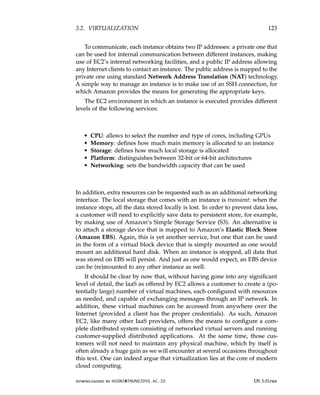
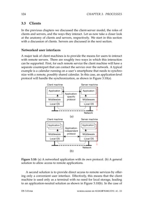
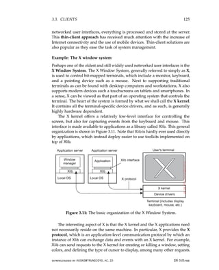
![126 CHAPTER 3. PROCESSES
In turn, the X kernel will react to local events such as keyboard and mouse
input by sending event packets back to Xlib.
Several applications can communicate at the same time with the X kernel.
There is one specific application that is given special rights, known as the
window manager. This application can dictate the “look and feel” of the
display as it appears to the user. For example, the window manager can
prescribe how each window is decorated with extra buttons, how windows
are to be placed on the display, and so on. Other applications will have to
adhere to these rules. In practice, this means that much of the interaction
between an application and an X terminal is redirected through a window
manager.
It is interesting to note how the X window system actually fits into client-
server computing. From what we have described so far, it should be clear
that the X kernel receives requests to manipulate the display. It gets these
requests from (possibly remote) applications. In this sense, the X kernel acts
as a server, while the applications play the role of clients. This terminology
has been adopted by X, and although strictly speaking it is correct, it can
easily lead to confusion.
Thin-client network computing
Obviously, applications manipulate a display using the specific display com-
mands as offered by X. These commands are generally sent over the network
where they are subsequently executed by the X kernel. By its nature, ap-
plications written for X should preferably separate application logic from
user-interface commands. Unfortunately, this is often not the case. As re-
ported by Lai and Nieh [2002] it turns out that much of the application logic
and user interaction are tightly coupled, meaning that an application will send
many requests to the X kernel for which it will expect a response before being
able to make a next step. This synchronous behavior may adversely affect
performance when operating over a wide-area network with long latencies.
There are several solutions to this problem. One is to re-engineer the
implementation of the X protocol, as is done with NX [Pinzari, 2003]. An
important part of this work concentrates on bandwidth reduction by reducing
the size of X messages. To this end, messages are considered to consist of a
fixed part, which is treated as an identifier, and a variable part. In many cases,
multiple messages will have the same identifier in which case they will often
contain similar data. This property can be used to send only the differences
between messages having the same identifier. By having the sender and
receiver maintain identifiers, decoding at the receiver can be readily applied.
Bandwidth reductions up to a factor 1000 have been reported, which allows X
to also run through low-bandwidth links of only 9600 kbps.
As an alternative to using X, researchers and practitioners have also sought
to let an application completely control the remote display, that is, up the
DS 3.01pre downloaded by HUSNI@TRUNOJOYO.AC.ID
126 CHAPTER 3. PROCESSES
In turn, the X kernel will react to local events such as keyboard and mouse
input by sending event packets back to Xlib.
Several applications can communicate at the same time with the X kernel.
There is one specific application that is given special rights, known as the
window manager. This application can dictate the “look and feel” of the
display as it appears to the user. For example, the window manager can
prescribe how each window is decorated with extra buttons, how windows
are to be placed on the display, and so on. Other applications will have to
adhere to these rules. In practice, this means that much of the interaction
between an application and an X terminal is redirected through a window
manager.
It is interesting to note how the X window system actually fits into client-
server computing. From what we have described so far, it should be clear
that the X kernel receives requests to manipulate the display. It gets these
requests from (possibly remote) applications. In this sense, the X kernel acts
as a server, while the applications play the role of clients. This terminology
has been adopted by X, and although strictly speaking it is correct, it can
easily lead to confusion.
Thin-client network computing
Obviously, applications manipulate a display using the specific display com-
mands as offered by X. These commands are generally sent over the network
where they are subsequently executed by the X kernel. By its nature, ap-
plications written for X should preferably separate application logic from
user-interface commands. Unfortunately, this is often not the case. As re-
ported by Lai and Nieh [2002] it turns out that much of the application logic
and user interaction are tightly coupled, meaning that an application will send
many requests to the X kernel for which it will expect a response before being
able to make a next step. This synchronous behavior may adversely affect
performance when operating over a wide-area network with long latencies.
There are several solutions to this problem. One is to re-engineer the
implementation of the X protocol, as is done with NX [Pinzari, 2003]. An
important part of this work concentrates on bandwidth reduction by reducing
the size of X messages. To this end, messages are considered to consist of a
fixed part, which is treated as an identifier, and a variable part. In many cases,
multiple messages will have the same identifier in which case they will often
contain similar data. This property can be used to send only the differences
between messages having the same identifier. By having the sender and
receiver maintain identifiers, decoding at the receiver can be readily applied.
Bandwidth reductions up to a factor 1000 have been reported, which allows X
to also run through low-bandwidth links of only 9600 kbps.
As an alternative to using X, researchers and practitioners have also sought
to let an application completely control the remote display, that is, up the
DS 3.01pre downloaded by HUSNI@TRUNOJOYO.AC.ID](https://image.slidesharecdn.com/distributed-systems-3rd-edition-251215232331-7e034da0/85/architectureec-distributed-systems-3rd-Edition-pdf-140-320.jpg)
![3.3. CLIENTS 127
pixel level. Changes in the bitmap are then sent over the network to the
display, where they are immediately transferred to the local frame buffer.
A well-known example of this approach is Virtual Network Computing
(VNC) [Richardson et al., 1998], which has been around ever since the late
1990s. Obviously, letting the application control the display requires sophis-
ticated encoding techniques in order to prevent bandwidth availability to
become a problem. For example, consider displaying a video stream at a rate
of 30 frames per second on a simple 320 × 240 screen. If each pixel is encoded
by 24 bits, then without an efficient encoding scheme, we would need a band-
width of approximately 53 Mbps. In practice, various encoding techniques
are used, yet choosing the best one is generally application dependent.
The drawback of sending raw pixel data in comparison to higher-level
protocols such as X is that it is impossible to make any use of application
semantics, as these are effectively lost at that level. Baratto et al. [2005] propose
a different technique. In their solution, referred to as THINC, they provide a
few high-level display commands that operate at the level of the video device
drivers. These commands are thus device dependent, more powerful than
raw pixel operations, but less powerful compared to what a protocol such as
X offers. The result is that display servers can be much simpler, which is good
for CPU usage, while at the same time application-dependent optimizations
can be used to reduce bandwidth and synchronization.
Client-side software for distribution transparency
Client software comprises more than just user interfaces. In many cases, parts
of the processing and data level in a client-server application are executed on
the client side as well. A special class is formed by embedded client software,
such as for automatic teller machines (ATMs), cash registers, barcode readers,
TV set-top boxes, etc. In these cases, the user interface is a relatively small part
of the client software, in contrast to the local processing and communication
facilities.
Besides the user interface and other application-related software, client soft-
ware comprises components for achieving distribution transparency. Ideally,
a client should not be aware that it is communicating with remote processes.
In contrast, distribution is often less transparent to servers for reasons of
performance and correctness.
Access transparency is generally handled through the generation of a
client stub from an interface definition of what the server has to offer. The
stub provides the same interface as the one available at the server, but hides
the possible differences in machine architectures, as well as the actual commu-
nication. The client stub transforms local calls to messages that are sent to the
server, and vice versa transforms messages from the server to return values as
one would expect when calling an ordinary procedure.
downloaded by HUSNI@TRUNOJOYO.AC.ID DS 3.01pre
3.3. CLIENTS 127
pixel level. Changes in the bitmap are then sent over the network to the
display, where they are immediately transferred to the local frame buffer.
A well-known example of this approach is Virtual Network Computing
(VNC) [Richardson et al., 1998], which has been around ever since the late
1990s. Obviously, letting the application control the display requires sophis-
ticated encoding techniques in order to prevent bandwidth availability to
become a problem. For example, consider displaying a video stream at a rate
of 30 frames per second on a simple 320 × 240 screen. If each pixel is encoded
by 24 bits, then without an efficient encoding scheme, we would need a band-
width of approximately 53 Mbps. In practice, various encoding techniques
are used, yet choosing the best one is generally application dependent.
The drawback of sending raw pixel data in comparison to higher-level
protocols such as X is that it is impossible to make any use of application
semantics, as these are effectively lost at that level. Baratto et al. [2005] propose
a different technique. In their solution, referred to as THINC, they provide a
few high-level display commands that operate at the level of the video device
drivers. These commands are thus device dependent, more powerful than
raw pixel operations, but less powerful compared to what a protocol such as
X offers. The result is that display servers can be much simpler, which is good
for CPU usage, while at the same time application-dependent optimizations
can be used to reduce bandwidth and synchronization.
Client-side software for distribution transparency
Client software comprises more than just user interfaces. In many cases, parts
of the processing and data level in a client-server application are executed on
the client side as well. A special class is formed by embedded client software,
such as for automatic teller machines (ATMs), cash registers, barcode readers,
TV set-top boxes, etc. In these cases, the user interface is a relatively small part
of the client software, in contrast to the local processing and communication
facilities.
Besides the user interface and other application-related software, client soft-
ware comprises components for achieving distribution transparency. Ideally,
a client should not be aware that it is communicating with remote processes.
In contrast, distribution is often less transparent to servers for reasons of
performance and correctness.
Access transparency is generally handled through the generation of a
client stub from an interface definition of what the server has to offer. The
stub provides the same interface as the one available at the server, but hides
the possible differences in machine architectures, as well as the actual commu-
nication. The client stub transforms local calls to messages that are sent to the
server, and vice versa transforms messages from the server to return values as
one would expect when calling an ordinary procedure.
downloaded by HUSNI@TRUNOJOYO.AC.ID DS 3.01pre](https://image.slidesharecdn.com/distributed-systems-3rd-edition-251215232331-7e034da0/85/architectureec-distributed-systems-3rd-Edition-pdf-141-320.jpg)
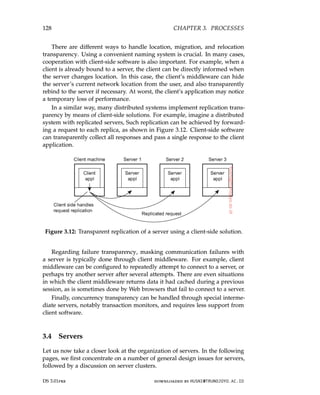
![3.4. SERVERS 129
General design issues
A server is a process implementing a specific service on behalf of a collection
of clients. In essence, each server is organized in the same way: it waits for an
incoming request from a client and subsequently ensures that the request is
taken care of, after which it waits for the next incoming request.
Concurrent versus iterative servers
There are several ways to organize servers. In the case of an iterative server,
the server itself handles the request and, if necessary, returns a response to the
requesting client. A concurrent server does not handle the request itself, but
passes it to a separate thread or another process, after which it immediately
waits for the next incoming request. A multithreaded server is an example of
a concurrent server. An alternative implementation of a concurrent server is to
fork a new process for each new incoming request. This approach is followed
in many Unix systems. The thread or process that handles the request is
responsible for returning a response to the requesting client.
Contacting a server: end points
Another issue is where clients contact a server. In all cases, clients send
requests to an end point, also called a port, at the machine where the server
is running. Each server listens to a specific end point. How do clients know
the end point of a service? One approach is to globally assign end points for
well-known services. For example, servers that handle Internet FTP requests
always listen to TCP port 21. Likewise, an HTTP server for the World Wide
Web will always listen to TCP port 80. These end points have been assigned
by the Internet Assigned Numbers Authority (IANA), and are documented
in [Reynolds and Postel, 1994]. With assigned end points, the client needs to
find only the network address of the machine where the server is running.
Name services can be used for that purpose.
There are many services that do not require a preassigned end point.
For example, a time-of-day server may use an end point that is dynamically
assigned to it by its local operating system. In that case, a client will first
have to look up the end point. One solution is to have a special daemon
running on each machine that runs servers. The daemon keeps track of the
current end point of each service implemented by a co-located server. The
daemon itself listens to a well-known end point. A client will first contact the
daemon, request the end point, and then contact the specific server, as shown
in Figure 3.13(a).
It is common to associate an end point with a specific service. However,
actually implementing each service by means of a separate server may be
a waste of resources. For example, in a typical Unix system, it is common
to have lots of servers running simultaneously, with most of them passively
downloaded by HUSNI@TRUNOJOYO.AC.ID DS 3.01pre
3.4. SERVERS 129
General design issues
A server is a process implementing a specific service on behalf of a collection
of clients. In essence, each server is organized in the same way: it waits for an
incoming request from a client and subsequently ensures that the request is
taken care of, after which it waits for the next incoming request.
Concurrent versus iterative servers
There are several ways to organize servers. In the case of an iterative server,
the server itself handles the request and, if necessary, returns a response to the
requesting client. A concurrent server does not handle the request itself, but
passes it to a separate thread or another process, after which it immediately
waits for the next incoming request. A multithreaded server is an example of
a concurrent server. An alternative implementation of a concurrent server is to
fork a new process for each new incoming request. This approach is followed
in many Unix systems. The thread or process that handles the request is
responsible for returning a response to the requesting client.
Contacting a server: end points
Another issue is where clients contact a server. In all cases, clients send
requests to an end point, also called a port, at the machine where the server
is running. Each server listens to a specific end point. How do clients know
the end point of a service? One approach is to globally assign end points for
well-known services. For example, servers that handle Internet FTP requests
always listen to TCP port 21. Likewise, an HTTP server for the World Wide
Web will always listen to TCP port 80. These end points have been assigned
by the Internet Assigned Numbers Authority (IANA), and are documented
in [Reynolds and Postel, 1994]. With assigned end points, the client needs to
find only the network address of the machine where the server is running.
Name services can be used for that purpose.
There are many services that do not require a preassigned end point.
For example, a time-of-day server may use an end point that is dynamically
assigned to it by its local operating system. In that case, a client will first
have to look up the end point. One solution is to have a special daemon
running on each machine that runs servers. The daemon keeps track of the
current end point of each service implemented by a co-located server. The
daemon itself listens to a well-known end point. A client will first contact the
daemon, request the end point, and then contact the specific server, as shown
in Figure 3.13(a).
It is common to associate an end point with a specific service. However,
actually implementing each service by means of a separate server may be
a waste of resources. For example, in a typical Unix system, it is common
to have lots of servers running simultaneously, with most of them passively
downloaded by HUSNI@TRUNOJOYO.AC.ID DS 3.01pre](https://image.slidesharecdn.com/distributed-systems-3rd-edition-251215232331-7e034da0/85/architectureec-distributed-systems-3rd-Edition-pdf-143-320.jpg)
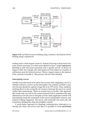
![3.4. SERVERS 131
data, which is data that is to be processed by the server before any other data
from that client. One solution is to let the server listen to a separate control
end point to which the client sends out-of-band data, while at the same time
listening (with a lower priority) to the end point through which the normal
data passes. Another solution is to send out-of-band data across the same
connection through which the client is sending the original request. In TCP,
for example, it is possible to transmit urgent data. When urgent data are
received at the server, the latter is interrupted (e.g., through a signal in Unix
systems), after which it can inspect the data and handle them accordingly.
Stateless versus stateful servers
A final, important design issue, is whether or not the server is stateless. A
stateless server does not keep information on the state of its clients, and can
change its own state without having to inform any client [Birman, 2012]. A
Web server, for example, is stateless. It merely responds to incoming HTTP
requests, which can be either for uploading a file to the server or (most often)
for fetching a file. When the request has been processed, the Web server
forgets the client completely. Likewise, the collection of files that a Web server
manages (possibly in cooperation with a file server), can be changed without
clients having to be informed.
Note that in many stateless designs, the server actually does maintain
information on its clients, but crucial is the fact that if this information is
lost, it will not lead to a disruption of the service offered by the server. For
example, a Web server generally logs all client requests. This information is
useful, for example, to decide whether certain documents should be replicated,
and where they should be replicated to. Clearly, there is no penalty other than
perhaps in the form of suboptimal performance if the log is lost.
A particular form of a stateless design is where the server maintains what
is known as soft state. In this case, the server promises to maintain state on
behalf of the client, but only for a limited time. After that time has expired,
the server falls back to default behavior, thereby discarding any information it
kept on account of the associated client. An example of this type of state is
a server promising to keep a client informed about updates, but only for a
limited time. After that, the client is required to poll the server for updates.
Soft-state approaches originate from protocol design in computer networks,
but can be equally applied to server design [Clark, 1989; Lui et al., 2004].
In contrast, a stateful server generally maintains persistent information
on its clients. This means that the information needs to be explicitly deleted
by the server. A typical example is a file server that allows a client to keep
a local copy of a file, even for performing update operations. Such a server
would maintain a table containing (client, file) entries. Such a table allows the
server to keep track of which client currently has the update permissions on
which file, and thus possibly also the most recent version of that file.
downloaded by HUSNI@TRUNOJOYO.AC.ID DS 3.01pre
3.4. SERVERS 131
data, which is data that is to be processed by the server before any other data
from that client. One solution is to let the server listen to a separate control
end point to which the client sends out-of-band data, while at the same time
listening (with a lower priority) to the end point through which the normal
data passes. Another solution is to send out-of-band data across the same
connection through which the client is sending the original request. In TCP,
for example, it is possible to transmit urgent data. When urgent data are
received at the server, the latter is interrupted (e.g., through a signal in Unix
systems), after which it can inspect the data and handle them accordingly.
Stateless versus stateful servers
A final, important design issue, is whether or not the server is stateless. A
stateless server does not keep information on the state of its clients, and can
change its own state without having to inform any client [Birman, 2012]. A
Web server, for example, is stateless. It merely responds to incoming HTTP
requests, which can be either for uploading a file to the server or (most often)
for fetching a file. When the request has been processed, the Web server
forgets the client completely. Likewise, the collection of files that a Web server
manages (possibly in cooperation with a file server), can be changed without
clients having to be informed.
Note that in many stateless designs, the server actually does maintain
information on its clients, but crucial is the fact that if this information is
lost, it will not lead to a disruption of the service offered by the server. For
example, a Web server generally logs all client requests. This information is
useful, for example, to decide whether certain documents should be replicated,
and where they should be replicated to. Clearly, there is no penalty other than
perhaps in the form of suboptimal performance if the log is lost.
A particular form of a stateless design is where the server maintains what
is known as soft state. In this case, the server promises to maintain state on
behalf of the client, but only for a limited time. After that time has expired,
the server falls back to default behavior, thereby discarding any information it
kept on account of the associated client. An example of this type of state is
a server promising to keep a client informed about updates, but only for a
limited time. After that, the client is required to poll the server for updates.
Soft-state approaches originate from protocol design in computer networks,
but can be equally applied to server design [Clark, 1989; Lui et al., 2004].
In contrast, a stateful server generally maintains persistent information
on its clients. This means that the information needs to be explicitly deleted
by the server. A typical example is a file server that allows a client to keep
a local copy of a file, even for performing update operations. Such a server
would maintain a table containing (client, file) entries. Such a table allows the
server to keep track of which client currently has the update permissions on
which file, and thus possibly also the most recent version of that file.
downloaded by HUSNI@TRUNOJOYO.AC.ID DS 3.01pre](https://image.slidesharecdn.com/distributed-systems-3rd-edition-251215232331-7e034da0/85/architectureec-distributed-systems-3rd-Edition-pdf-145-320.jpg)
![132 CHAPTER 3. PROCESSES
This approach can improve the performance of read and write operations
as perceived by the client. Performance improvement over stateless servers
is often an important benefit of stateful designs. However, the example also
illustrates the major drawback of stateful servers. If the server crashes, it has
to recover its table of (client, file) entries, or otherwise it cannot guarantee
that it has processed the most recent updates on a file. In general, a stateful
server needs to recover its entire state as it was just before the crash. Enabling
recovery can introduce considerable complexity, as we discuss in . Chapter 8In
a stateless design, no special measures need to be taken at all for a crashed
server to recover. It simply starts running again, and waits for client requests
to come in.
Ling et al. [2004] argue that one should actually make a distinction between
(temporary) session state and permanent state. The example above is typical
for session state: it is associated with a series of operations by a single user
and should be maintained for a some time, but not indefinitely. As it turns
out, session state is often maintained in three-tiered client-server architectures,
where the application server actually needs to access a database server through
a series of queries before being able to respond to the requesting client. The
issue here is that no real harm is done if session state is lost, provided that
the client can simply re-issue the original request. This observation allows for
simpler and less reliable storage of state.
What remains for permanent state is typically information maintained
in databases, such as customer information, keys associated with purchased
software, etc. However, for most distributed systems, maintaining session state
already implies a stateful design requiring special measures when failures do
happen and making explicit assumptions about the durability of state stored
at the server. We will return to these matters extensively when discussing
fault tolerance.
When designing a server, the choice for a stateless or stateful design should
not affect the services provided by the server. For example, if files have to
be opened before they can be read from, or written to, then a stateless server
should one way or the other mimic this behavior. A common solution is that
the server responds to a read or write request by first opening the referred
file, then does the actual read or write operation, and immediately closes the
file again.
In other cases, a server may want to keep a record on a client’s behavior so
that it can more effectively respond to its requests. For example, Web servers
sometimes offer the possibility to immediately direct a client to his favorite
pages. This approach is possible only if the server has history information on
that client. When the server cannot maintain state, a common solution is then
to let the client send along additional information on its previous accesses.
In the case of the Web, this information is often transparently stored by the
client’s browser in what is called a cookie, which is a small piece of data
DS 3.01pre downloaded by HUSNI@TRUNOJOYO.AC.ID
132 CHAPTER 3. PROCESSES
This approach can improve the performance of read and write operations
as perceived by the client. Performance improvement over stateless servers
is often an important benefit of stateful designs. However, the example also
illustrates the major drawback of stateful servers. If the server crashes, it has
to recover its table of (client, file) entries, or otherwise it cannot guarantee
that it has processed the most recent updates on a file. In general, a stateful
server needs to recover its entire state as it was just before the crash. Enabling
recovery can introduce considerable complexity, as we discuss in . Chapter 8In
a stateless design, no special measures need to be taken at all for a crashed
server to recover. It simply starts running again, and waits for client requests
to come in.
Ling et al. [2004] argue that one should actually make a distinction between
(temporary) session state and permanent state. The example above is typical
for session state: it is associated with a series of operations by a single user
and should be maintained for a some time, but not indefinitely. As it turns
out, session state is often maintained in three-tiered client-server architectures,
where the application server actually needs to access a database server through
a series of queries before being able to respond to the requesting client. The
issue here is that no real harm is done if session state is lost, provided that
the client can simply re-issue the original request. This observation allows for
simpler and less reliable storage of state.
What remains for permanent state is typically information maintained
in databases, such as customer information, keys associated with purchased
software, etc. However, for most distributed systems, maintaining session state
already implies a stateful design requiring special measures when failures do
happen and making explicit assumptions about the durability of state stored
at the server. We will return to these matters extensively when discussing
fault tolerance.
When designing a server, the choice for a stateless or stateful design should
not affect the services provided by the server. For example, if files have to
be opened before they can be read from, or written to, then a stateless server
should one way or the other mimic this behavior. A common solution is that
the server responds to a read or write request by first opening the referred
file, then does the actual read or write operation, and immediately closes the
file again.
In other cases, a server may want to keep a record on a client’s behavior so
that it can more effectively respond to its requests. For example, Web servers
sometimes offer the possibility to immediately direct a client to his favorite
pages. This approach is possible only if the server has history information on
that client. When the server cannot maintain state, a common solution is then
to let the client send along additional information on its previous accesses.
In the case of the Web, this information is often transparently stored by the
client’s browser in what is called a cookie, which is a small piece of data
DS 3.01pre downloaded by HUSNI@TRUNOJOYO.AC.ID](https://image.slidesharecdn.com/distributed-systems-3rd-edition-251215232331-7e034da0/85/architectureec-distributed-systems-3rd-Edition-pdf-146-320.jpg)
![3.4. SERVERS 135
Figure 3.14: An object server supporting different activation policies.
The only issue that is important to an object adapter is that it can extract an
object reference from an invocation request, and subsequently dispatch the
request to the referenced object, but now following a specific activation policy.
As is also illustrated in Figure 3.14 rather than passing the request directly
to the object, an adapter hands an invocation request to the server-side stub
of that object. The stub, also called a skeleton, is normally generated from
the interface definitions of the object, unmarshals the request and invokes the
appropriate method.
An object adapter can support different activation policies by simply
configuring it at runtime. For example, in CORBA-compliant systems [OMG,
2004a], it is possible to specify whether an object should continue to exist after
its associated adapter has stopped. Likewise, an adapter can be configured
to generate object identifiers, or to let the application provide one. As a
final example, an adapter can be configured to operate in single-threaded or
multithreaded mode as we explained above.
Note that although in Figure 3.14 we have spoken about objects, we
have said nothing about what these objects actually are. In particular, it
should be stressed that as part of the implementation of such an object the
server may (indirectly) access databases or call special library routines. The
implementation details are hidden for the object adapter who communicates
only with a skeleton. As such, the actual implementation may have nothing
to do with what we often see with language-level (i.e., compile-time) objects.
For this reason, a different terminology is generally adopted. A servant is the
downloaded by HUSNI@TRUNOJOYO.AC.ID DS 3.01pre
3.4. SERVERS 135
Figure 3.14: An object server supporting different activation policies.
The only issue that is important to an object adapter is that it can extract an
object reference from an invocation request, and subsequently dispatch the
request to the referenced object, but now following a specific activation policy.
As is also illustrated in Figure 3.14 rather than passing the request directly
to the object, an adapter hands an invocation request to the server-side stub
of that object. The stub, also called a skeleton, is normally generated from
the interface definitions of the object, unmarshals the request and invokes the
appropriate method.
An object adapter can support different activation policies by simply
configuring it at runtime. For example, in CORBA-compliant systems [OMG,
2004a], it is possible to specify whether an object should continue to exist after
its associated adapter has stopped. Likewise, an adapter can be configured
to generate object identifiers, or to let the application provide one. As a
final example, an adapter can be configured to operate in single-threaded or
multithreaded mode as we explained above.
Note that although in Figure 3.14 we have spoken about objects, we
have said nothing about what these objects actually are. In particular, it
should be stressed that as part of the implementation of such an object the
server may (indirectly) access databases or call special library routines. The
implementation details are hidden for the object adapter who communicates
only with a skeleton. As such, the actual implementation may have nothing
to do with what we often see with language-level (i.e., compile-time) objects.
For this reason, a different terminology is generally adopted. A servant is the
downloaded by HUSNI@TRUNOJOYO.AC.ID DS 3.01pre](https://image.slidesharecdn.com/distributed-systems-3rd-edition-251215232331-7e034da0/85/architectureec-distributed-systems-3rd-Edition-pdf-149-320.jpg)
![136 CHAPTER 3. PROCESSES
general term for a piece of code that forms the implementation of an object.
Note 3.6 (Example: The Ice runtime system)
Let us briefly consider the Ice distributed-object system, which has been partly
developed in response to the intricacies of commercial object-based distributed
systems [Henning, 2004]. An object server in Ice is nothing but an ordinary
process that simply starts with initializing the Ice runtime system (RTS). The
basis of the runtime environment is formed by what is called a communicator. A
communicator is a component that manages a number of basic resources, of which
the most important one is formed by a pool of threads. Likewise, it will have
associated dynamically allocated memory, and so on. In addition, a communicator
provides the means for configuring the environment. For example, it is possible
to specify maximum message lengths, maximum invocation retries, and so on.
Normally, an object server would have only a single communicator. However,
when different applications need to be fully separated and protected from each
other, a separate communicator (with possibly a different configuration) can be
created within the same process. At the very least, such an approach would
separate the different thread pools so that if one application has consumed all its
threads, then this would not affect the other application.
A communicator can also be used to create an object adapter, such as shown
in Figure 3.15. We note that the code is simplified and incomplete. More examples
and detailed information on Ice can be found in Henning and Spruiell [2005].
main(int argc, char* argv[]) {
Ice::Communicator ic;
Ice::ObjectAdapter adapter;
Ice::Object object;
ic = Ice::initialize(argc, argv);
adapter = ic-createObjectAdapterWithEnd Points( MyAdapter,tcp -p 10000);
object = new MyObject;
adapter-add(object, objectID);
adapter-activate();
ic-waitForShutdown();
}
Figure 3.15: Example of creating an object server in Ice.
In this example, we start with creating and initializing the runtime environ-
ment. When that is done, an object adapter is created. In this case, it is instructed
to listen for incoming TCP connections on port 10000. Note that the adapter
is created in the context of the just created communicator. We are now in the
position to create an object and to subsequently add that object to the adapter.
Finally, the adapter is activated, meaning that, under the hood, a thread is activated
that will start listening for incoming requests.
This code does not yet show much differentiation in activation policies. Poli-
cies can be changed by modifying the properties of an adapter. One family of
properties is related to maintaining an adapter-specific set of threads that are used
DS 3.01pre downloaded by HUSNI@TRUNOJOYO.AC.ID
136 CHAPTER 3. PROCESSES
general term for a piece of code that forms the implementation of an object.
Note 3.6 (Example: The Ice runtime system)
Let us briefly consider the Ice distributed-object system, which has been partly
developed in response to the intricacies of commercial object-based distributed
systems [Henning, 2004]. An object server in Ice is nothing but an ordinary
process that simply starts with initializing the Ice runtime system (RTS). The
basis of the runtime environment is formed by what is called a communicator. A
communicator is a component that manages a number of basic resources, of which
the most important one is formed by a pool of threads. Likewise, it will have
associated dynamically allocated memory, and so on. In addition, a communicator
provides the means for configuring the environment. For example, it is possible
to specify maximum message lengths, maximum invocation retries, and so on.
Normally, an object server would have only a single communicator. However,
when different applications need to be fully separated and protected from each
other, a separate communicator (with possibly a different configuration) can be
created within the same process. At the very least, such an approach would
separate the different thread pools so that if one application has consumed all its
threads, then this would not affect the other application.
A communicator can also be used to create an object adapter, such as shown
in Figure 3.15. We note that the code is simplified and incomplete. More examples
and detailed information on Ice can be found in Henning and Spruiell [2005].
main(int argc, char* argv[]) {
Ice::Communicator ic;
Ice::ObjectAdapter adapter;
Ice::Object object;
ic = Ice::initialize(argc, argv);
adapter = ic-createObjectAdapterWithEnd Points( MyAdapter,tcp -p 10000);
object = new MyObject;
adapter-add(object, objectID);
adapter-activate();
ic-waitForShutdown();
}
Figure 3.15: Example of creating an object server in Ice.
In this example, we start with creating and initializing the runtime environ-
ment. When that is done, an object adapter is created. In this case, it is instructed
to listen for incoming TCP connections on port 10000. Note that the adapter
is created in the context of the just created communicator. We are now in the
position to create an object and to subsequently add that object to the adapter.
Finally, the adapter is activated, meaning that, under the hood, a thread is activated
that will start listening for incoming requests.
This code does not yet show much differentiation in activation policies. Poli-
cies can be changed by modifying the properties of an adapter. One family of
properties is related to maintaining an adapter-specific set of threads that are used
DS 3.01pre downloaded by HUSNI@TRUNOJOYO.AC.ID](https://image.slidesharecdn.com/distributed-systems-3rd-edition-251215232331-7e034da0/85/architectureec-distributed-systems-3rd-Edition-pdf-150-320.jpg)
![138 CHAPTER 3. PROCESSES
provides the support to separate application functionality from systems-oriented
functionality. The latter includes functions for looking up objects, storing objects,
letting objects be part of a transaction, and so on. How to develop EJBs is described
in detail by Schildt [2010].
Figure 3.16: General architecture of an EJB server.
With this separation in mind, EJBs can be pictured as shown in Figure 3.16.
The important issue is that an EJB is embedded inside a container which effectively
provides interfaces to underlying services that are implemented by the application
server. The container can more or less automatically bind the EJB to these services,
meaning that the correct references are readily available to a programmer. Typical
services include those for remote method invocation (RMI), database access
(JDBC), naming (JNDI), and messaging (JMS). Making use of these services is
more or less automated, but does require that the programmer makes a distinction
between four kinds of EJBs:
1. Stateless session beans
2. Stateful session beans
3. Entity beans
4. Message-driven beans
As its name suggests, a stateless session bean is an object that is invoked
once, does its work, after which it discards any information it needed to perform
the service it offered to a client. For example, a stateless session bean could be
used to implement a service that lists the top-ranked books. In this case, the bean
would typically consist of an SQL query that is submitted to a database. The
results would be put into a special format that the client can handle, after which
its work would have been completed and the listed books discarded.
In contrast, a stateful session bean maintains client-related state. The canoni-
cal example is a bean implementing an electronic shopping cart. In this case, a
client would typically be able to put things in a cart, remove items, and use the
cart to go to an electronic checkout. The bean, in turn, would typically access
databases for getting current prices and information on the number of items still
in stock. However, its lifetime would still be limited, which is why it is referred to
as a session bean: when the client is finished (possibly having invoked the object
several times), the bean will automatically be destroyed.
DS 3.01pre downloaded by HUSNI@TRUNOJOYO.AC.ID
138 CHAPTER 3. PROCESSES
provides the support to separate application functionality from systems-oriented
functionality. The latter includes functions for looking up objects, storing objects,
letting objects be part of a transaction, and so on. How to develop EJBs is described
in detail by Schildt [2010].
Figure 3.16: General architecture of an EJB server.
With this separation in mind, EJBs can be pictured as shown in Figure 3.16.
The important issue is that an EJB is embedded inside a container which effectively
provides interfaces to underlying services that are implemented by the application
server. The container can more or less automatically bind the EJB to these services,
meaning that the correct references are readily available to a programmer. Typical
services include those for remote method invocation (RMI), database access
(JDBC), naming (JNDI), and messaging (JMS). Making use of these services is
more or less automated, but does require that the programmer makes a distinction
between four kinds of EJBs:
1. Stateless session beans
2. Stateful session beans
3. Entity beans
4. Message-driven beans
As its name suggests, a stateless session bean is an object that is invoked
once, does its work, after which it discards any information it needed to perform
the service it offered to a client. For example, a stateless session bean could be
used to implement a service that lists the top-ranked books. In this case, the bean
would typically consist of an SQL query that is submitted to a database. The
results would be put into a special format that the client can handle, after which
its work would have been completed and the listed books discarded.
In contrast, a stateful session bean maintains client-related state. The canoni-
cal example is a bean implementing an electronic shopping cart. In this case, a
client would typically be able to put things in a cart, remove items, and use the
cart to go to an electronic checkout. The bean, in turn, would typically access
databases for getting current prices and information on the number of items still
in stock. However, its lifetime would still be limited, which is why it is referred to
as a session bean: when the client is finished (possibly having invoked the object
several times), the bean will automatically be destroyed.
DS 3.01pre downloaded by HUSNI@TRUNOJOYO.AC.ID](https://image.slidesharecdn.com/distributed-systems-3rd-edition-251215232331-7e034da0/85/architectureec-distributed-systems-3rd-Edition-pdf-152-320.jpg)
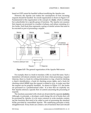
![3.4. SERVERS 141
match a specific function prototype (i.e., list of parameters and return type).
A module developer will write functions for specific hooks. When compiling
Apache, the developer specifies which function should be added to which
hook. The latter is shown in Figure 3.17 as the various links between functions
and hooks.
Because there may be tens of modules, each hook will generally contain
several functions. Normally, modules are considered to be mutual indepen-
dent, so that functions in the same hook will be executed in some arbitrary
order. However, Apache can also handle module dependencies by letting
a developer specify an ordering in which functions from different modules
should be processed. By and large, the result is a Web server that is ex-
tremely versatile. Detailed information on configuring Apache, as well as an
introduction to how it can be extended is found in [Laurie and Laurie, 2002].
Server clusters
In Chapter 1, we briefly discussed cluster computing as one of the many
appearances of distributed systems. We now take a closer look at the organiza-
tion of server clusters, along with the salient design issues. We first consider
common server clusters that are organized in local-area networks. A special
group is formed by wide-area server clusters, which we subsequently discuss.
Local-area clusters
Simply put, a server cluster is nothing else but a collection of machines
connected through a network, where each machine runs one or more servers.
The server clusters that we consider here, are the ones in which the machines
are connected through a local-area network, often offering high bandwidth
and low latency.
General organization In many cases, a server cluster is logically organized
into three tiers, as shown in Figure 3.18. The first tier consists of a (logical)
switch through which client requests are routed. Such a switch can vary
widely. For example, transport-layer switches accept incoming TCP connection
requests and pass requests on to one of servers in the cluster. A completely
different example is a Web server that accepts incoming HTTP requests, but
that partly passes requests to application servers for further processing only
to later collect results from those servers and return an HTTP response.
As in any multitiered client-server architecture, many server clusters also
contain servers dedicated to application processing. In cluster computing,
these are typically servers running on high-performance hardware dedicated
to delivering compute power. However, in the case of enterprise server
clusters, it may be the case that applications need only run on relatively
downloaded by HUSNI@TRUNOJOYO.AC.ID DS 3.01pre
3.4. SERVERS 141
match a specific function prototype (i.e., list of parameters and return type).
A module developer will write functions for specific hooks. When compiling
Apache, the developer specifies which function should be added to which
hook. The latter is shown in Figure 3.17 as the various links between functions
and hooks.
Because there may be tens of modules, each hook will generally contain
several functions. Normally, modules are considered to be mutual indepen-
dent, so that functions in the same hook will be executed in some arbitrary
order. However, Apache can also handle module dependencies by letting
a developer specify an ordering in which functions from different modules
should be processed. By and large, the result is a Web server that is ex-
tremely versatile. Detailed information on configuring Apache, as well as an
introduction to how it can be extended is found in [Laurie and Laurie, 2002].
Server clusters
In Chapter 1, we briefly discussed cluster computing as one of the many
appearances of distributed systems. We now take a closer look at the organiza-
tion of server clusters, along with the salient design issues. We first consider
common server clusters that are organized in local-area networks. A special
group is formed by wide-area server clusters, which we subsequently discuss.
Local-area clusters
Simply put, a server cluster is nothing else but a collection of machines
connected through a network, where each machine runs one or more servers.
The server clusters that we consider here, are the ones in which the machines
are connected through a local-area network, often offering high bandwidth
and low latency.
General organization In many cases, a server cluster is logically organized
into three tiers, as shown in Figure 3.18. The first tier consists of a (logical)
switch through which client requests are routed. Such a switch can vary
widely. For example, transport-layer switches accept incoming TCP connection
requests and pass requests on to one of servers in the cluster. A completely
different example is a Web server that accepts incoming HTTP requests, but
that partly passes requests to application servers for further processing only
to later collect results from those servers and return an HTTP response.
As in any multitiered client-server architecture, many server clusters also
contain servers dedicated to application processing. In cluster computing,
these are typically servers running on high-performance hardware dedicated
to delivering compute power. However, in the case of enterprise server
clusters, it may be the case that applications need only run on relatively
downloaded by HUSNI@TRUNOJOYO.AC.ID DS 3.01pre](https://image.slidesharecdn.com/distributed-systems-3rd-edition-251215232331-7e034da0/85/architectureec-distributed-systems-3rd-Edition-pdf-155-320.jpg)
![142 CHAPTER 3. PROCESSES
Figure 3.18: The general organization of a three-tiered server cluster.
low-end machines, as the required compute power is not the bottleneck, but
access to storage is.
This brings us the third tier, which consists of data-processing servers,
notably file and database servers. Again, depending on the usage of the server
cluster, these servers may be running on specialized machines, configured for
high-speed disk access and having large server-side data caches.
Of course, not all server clusters will follow this strict separation. It is
frequently the case that each machine is equipped with its own local storage,
often integrating application and data processing in a single server leading to
a two-tiered architecture. For example, when dealing with streaming media
by means of a server cluster, it is common to deploy a two-tiered system
architecture, where each machine acts as a dedicated media server [Steinmetz
and Nahrstedt, 2004].
When a server cluster offers multiple services, it may happen that different
machines run different application servers. As a consequence, the switch will
have to be able to distinguish services or otherwise it cannot forward requests
to the proper machines. As a consequence, we may find that certain machines
are temporarily idle, while others are receiving an overload of requests. What
would be useful is to temporarily migrate services to idle machines. A solution
is to use virtual machines allowing a relatively easy migration of code to real
machines.
Request dispatching Let us now take a closer look at the first tier, consisting
of the switch, also known as the front end. An important design goal for
server clusters is to hide the fact that there are multiple servers. In other
words, client applications running on remote machines should have no need
to know anything about the internal organization of the cluster. This access
transparency is invariably offered by means of a single access point, in turn
DS 3.01pre downloaded by HUSNI@TRUNOJOYO.AC.ID
142 CHAPTER 3. PROCESSES
Figure 3.18: The general organization of a three-tiered server cluster.
low-end machines, as the required compute power is not the bottleneck, but
access to storage is.
This brings us the third tier, which consists of data-processing servers,
notably file and database servers. Again, depending on the usage of the server
cluster, these servers may be running on specialized machines, configured for
high-speed disk access and having large server-side data caches.
Of course, not all server clusters will follow this strict separation. It is
frequently the case that each machine is equipped with its own local storage,
often integrating application and data processing in a single server leading to
a two-tiered architecture. For example, when dealing with streaming media
by means of a server cluster, it is common to deploy a two-tiered system
architecture, where each machine acts as a dedicated media server [Steinmetz
and Nahrstedt, 2004].
When a server cluster offers multiple services, it may happen that different
machines run different application servers. As a consequence, the switch will
have to be able to distinguish services or otherwise it cannot forward requests
to the proper machines. As a consequence, we may find that certain machines
are temporarily idle, while others are receiving an overload of requests. What
would be useful is to temporarily migrate services to idle machines. A solution
is to use virtual machines allowing a relatively easy migration of code to real
machines.
Request dispatching Let us now take a closer look at the first tier, consisting
of the switch, also known as the front end. An important design goal for
server clusters is to hide the fact that there are multiple servers. In other
words, client applications running on remote machines should have no need
to know anything about the internal organization of the cluster. This access
transparency is invariably offered by means of a single access point, in turn
DS 3.01pre downloaded by HUSNI@TRUNOJOYO.AC.ID](https://image.slidesharecdn.com/distributed-systems-3rd-edition-251215232331-7e034da0/85/architectureec-distributed-systems-3rd-Edition-pdf-156-320.jpg)
![3.4. SERVERS 143
implemented through some kind of hardware switch such as a dedicated
machine.
The switch forms the entry point for the server cluster, offering a single
network address. For scalability and availability, a server cluster may have
multiple access points, where each access point is then realized by a separate
dedicated machine. We consider only the case of a single access point.
A standard way of accessing a server cluster is to set up a TCP connection
over which application-level requests are then sent as part of a session. A
session ends by tearing down the connection. In the case of transport-layer
switches, the switch accepts incoming TCP connection requests, and hands
off such connections to one of the servers. There are essentially two ways how
the switch can operate [Cardellini et al., 2002].
In the first case, the client sets up a TCP connection such that all requests
and responses pass through the switch. The switch, in turn, will set up a TCP
connection with a selected server and pass client requests to that server, and
also accept server responses (which it will pass on to the client). In effect,
the switch sits in the middle of a TCP connection between the client and a
selected server, rewriting the source and destination addresses when passing
TCP segments. This approach is a form of network address translation
(NAT) [Srisuresh and Holdrege, 1999].
Alternatively, the switch can actually hand off the connection to a selected
server such that all responses are directly communicated to the client without
passing through the server [Hunt et al., 1997; Pai et al., 1998]. The principle
working of what is commonly known as TCP handoff is shown in Figure 3.19.
Figure 3.19: The principle of TCP handoff.
When the switch receives a TCP connection request, it first identifies the
best server for handling that request, and forwards the request packet to
that server. The server, in turn, will send an acknowledgment back to the
requesting client, but inserting the switch’s IP address as the source field of
the header of the IP packet carrying the TCP segment. Note that this address
rewriting is necessary for the client to continue executing the TCP protocol: it
downloaded by HUSNI@TRUNOJOYO.AC.ID DS 3.01pre
3.4. SERVERS 143
implemented through some kind of hardware switch such as a dedicated
machine.
The switch forms the entry point for the server cluster, offering a single
network address. For scalability and availability, a server cluster may have
multiple access points, where each access point is then realized by a separate
dedicated machine. We consider only the case of a single access point.
A standard way of accessing a server cluster is to set up a TCP connection
over which application-level requests are then sent as part of a session. A
session ends by tearing down the connection. In the case of transport-layer
switches, the switch accepts incoming TCP connection requests, and hands
off such connections to one of the servers. There are essentially two ways how
the switch can operate [Cardellini et al., 2002].
In the first case, the client sets up a TCP connection such that all requests
and responses pass through the switch. The switch, in turn, will set up a TCP
connection with a selected server and pass client requests to that server, and
also accept server responses (which it will pass on to the client). In effect,
the switch sits in the middle of a TCP connection between the client and a
selected server, rewriting the source and destination addresses when passing
TCP segments. This approach is a form of network address translation
(NAT) [Srisuresh and Holdrege, 1999].
Alternatively, the switch can actually hand off the connection to a selected
server such that all responses are directly communicated to the client without
passing through the server [Hunt et al., 1997; Pai et al., 1998]. The principle
working of what is commonly known as TCP handoff is shown in Figure 3.19.
Figure 3.19: The principle of TCP handoff.
When the switch receives a TCP connection request, it first identifies the
best server for handling that request, and forwards the request packet to
that server. The server, in turn, will send an acknowledgment back to the
requesting client, but inserting the switch’s IP address as the source field of
the header of the IP packet carrying the TCP segment. Note that this address
rewriting is necessary for the client to continue executing the TCP protocol: it
downloaded by HUSNI@TRUNOJOYO.AC.ID DS 3.01pre](https://image.slidesharecdn.com/distributed-systems-3rd-edition-251215232331-7e034da0/85/architectureec-distributed-systems-3rd-Edition-pdf-157-320.jpg)
![144 CHAPTER 3. PROCESSES
is expecting an answer back from the switch, not from some arbitrary server
it has never heard of before. Clearly, a TCP-handoff implementation requires
operating-system level modifications. TCP handoff is especially effective when
responses are much larger than requests, as in the case of Web servers.
It can already be seen that the switch can play an important role in dis-
tributing the load among the various servers. By deciding where to forward a
request to, the switch also decides which server is to handle further processing
of the request. The simplest load-balancing policy that the switch can follow
is round robin: each time it picks the next server from its list to forward a
request to. Of course, the switch will have to keep track to which server it
handed off a TCP connection, at least until that connection is torn down. As
it turns out, maintaining this state and handing off subsequent TCP segments
belonging to the same TCP connection, may actually slow down the switch.
More advanced server selection criteria can be deployed as well. For
example, assume multiple services are offered by the server cluster. If the
switch can distinguish those services when a request comes in, it can then take
informed decisions on where to forward the request to. This server selection
can still take place at the transport level, provided services are distinguished
by means of a port number. In the case of transport-level switches, as we have
discussed so far, decisions on where to forward an incoming request is based
on transport-level information only. One step further is to have the switch
actually inspect the payload of the incoming request. This content-aware
request distribution can be applied only if it is known what that payload
looks like. For example, in the case of Web servers, the switch can expect an
HTTP request, based on which it can then decide who is to process it.
Note 3.8 (Advanced: Efficient content-aware request distribution)
Obviously, the design of the switch is crucial, as it can easily become a bottleneck
with all traffic passing through it. Transport-level switches are generally very
efficient. However, content-aware switches operating at the level of the application
layer that inspect the payload of an incoming request, may actually need to do a
lot of processing.
Content-aware request distribution has several advantages. For example, if
the switch always forwards requests for the same file to the same server, that
server may be able to effectively cache the file resulting in higher response times.
Likewise, we may decide to distribute a set of files to specific servers, making a
distinction, for example, between streaming media files, images, text files, but
also perhaps actual databases. Being able to make such a distinction will allow to
install dedicated servers in the second tier.
Ideally, the switch would be as efficient as a normal transport-level switch, yet
have the functionality for content-aware distribution. Aron et al. [2000] propose a
scheme by which the work for inspecting the payload of an incoming request is
distributed across several servers, and combine this distribution with transport-
level switching. The switch now has two tasks. First, when a request initially
DS 3.01pre downloaded by HUSNI@TRUNOJOYO.AC.ID
144 CHAPTER 3. PROCESSES
is expecting an answer back from the switch, not from some arbitrary server
it has never heard of before. Clearly, a TCP-handoff implementation requires
operating-system level modifications. TCP handoff is especially effective when
responses are much larger than requests, as in the case of Web servers.
It can already be seen that the switch can play an important role in dis-
tributing the load among the various servers. By deciding where to forward a
request to, the switch also decides which server is to handle further processing
of the request. The simplest load-balancing policy that the switch can follow
is round robin: each time it picks the next server from its list to forward a
request to. Of course, the switch will have to keep track to which server it
handed off a TCP connection, at least until that connection is torn down. As
it turns out, maintaining this state and handing off subsequent TCP segments
belonging to the same TCP connection, may actually slow down the switch.
More advanced server selection criteria can be deployed as well. For
example, assume multiple services are offered by the server cluster. If the
switch can distinguish those services when a request comes in, it can then take
informed decisions on where to forward the request to. This server selection
can still take place at the transport level, provided services are distinguished
by means of a port number. In the case of transport-level switches, as we have
discussed so far, decisions on where to forward an incoming request is based
on transport-level information only. One step further is to have the switch
actually inspect the payload of the incoming request. This content-aware
request distribution can be applied only if it is known what that payload
looks like. For example, in the case of Web servers, the switch can expect an
HTTP request, based on which it can then decide who is to process it.
Note 3.8 (Advanced: Efficient content-aware request distribution)
Obviously, the design of the switch is crucial, as it can easily become a bottleneck
with all traffic passing through it. Transport-level switches are generally very
efficient. However, content-aware switches operating at the level of the application
layer that inspect the payload of an incoming request, may actually need to do a
lot of processing.
Content-aware request distribution has several advantages. For example, if
the switch always forwards requests for the same file to the same server, that
server may be able to effectively cache the file resulting in higher response times.
Likewise, we may decide to distribute a set of files to specific servers, making a
distinction, for example, between streaming media files, images, text files, but
also perhaps actual databases. Being able to make such a distinction will allow to
install dedicated servers in the second tier.
Ideally, the switch would be as efficient as a normal transport-level switch, yet
have the functionality for content-aware distribution. Aron et al. [2000] propose a
scheme by which the work for inspecting the payload of an incoming request is
distributed across several servers, and combine this distribution with transport-
level switching. The switch now has two tasks. First, when a request initially
DS 3.01pre downloaded by HUSNI@TRUNOJOYO.AC.ID](https://image.slidesharecdn.com/distributed-systems-3rd-edition-251215232331-7e034da0/85/architectureec-distributed-systems-3rd-Edition-pdf-158-320.jpg)
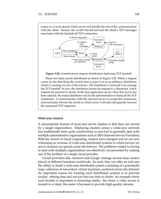
![146 CHAPTER 3. PROCESSES
Note that if wide-area locality is not critical, it may suffice, or even be
better, to place virtual machines in a single data center, so that interprocess
communication can benefit from low-latency local networks. The price to pay
may be higher latencies between clients and the service running in a remote
data center.
Request dispatching If wide-area locality is an issue, then request dispatch-
ing becomes important: if a client accesses a service, its request should be
forwarded to a nearby server, that is, a server that will allow communication
with that client to be fast. Deciding which server should handle the client’s
request is an issue of redirection policy [Sivasubramanian et al., 2004b]. If we
assume that a client will initially contact a request dispatcher analogous to
the switch in our discussion of local-area clusters, then that dispatcher will
have to estimate the latency between the client and several servers. How such
an estimation can be made is discussed in Section 6.5.
Once a server has been selected, the dispatcher will have to inform the
client. Several redirection mechanisms are possible. A popular one is when
the dispatcher is actually a DNS name server. Internet or Web-based services
are often looked up in the Domain Name System (DNS). A client provides
a domain name such as service.organization.org to a local DNS server, which
eventually returns an IP address of the associated service, possibly after
having contacted other DNS servers. When sending its request to look up a
name, a client also sends its own IP address (DNS requests are sent as UDP
packets). In other words, the DNS server will also know the client’s IP address
which it can then subsequently use to select the best server for that client, and
returning a close-by IP address.
Unfortunately, this scheme is not perfect for two reasons. First, rather than
sending the client’s IP address, what happens is that the local DNS server that
is contacted by the client acts as a proxy for that client. In other words, not
the client’s IP address, but that of the local DNS server is used to identify the
location of the client. Mao et al. [2002] have shown that there may be a huge
additional communication cost, as the local DNS server is often not that local.
Secondly, depending on the scheme that is used for resolving a domain
name, it may even be the case that the address of the local DNS server is not
even being used. Instead, it may happen that the DNS server that is deciding
on which IP address to return, may be fooled by the fact that the requester
is yet another DNS server acting as an intermediate between the original
client and the deciding DNS server. In those case, locality awareness has been
completely lost.
Despite that DNS-based redirection may not always be very accurate, it
is widely deployed if only for the fact that it is relatively easy to implement
and also transparent to the client. In addition, there is no need to rely on
location-aware client-side software.
DS 3.01pre downloaded by HUSNI@TRUNOJOYO.AC.ID
146 CHAPTER 3. PROCESSES
Note that if wide-area locality is not critical, it may suffice, or even be
better, to place virtual machines in a single data center, so that interprocess
communication can benefit from low-latency local networks. The price to pay
may be higher latencies between clients and the service running in a remote
data center.
Request dispatching If wide-area locality is an issue, then request dispatch-
ing becomes important: if a client accesses a service, its request should be
forwarded to a nearby server, that is, a server that will allow communication
with that client to be fast. Deciding which server should handle the client’s
request is an issue of redirection policy [Sivasubramanian et al., 2004b]. If we
assume that a client will initially contact a request dispatcher analogous to
the switch in our discussion of local-area clusters, then that dispatcher will
have to estimate the latency between the client and several servers. How such
an estimation can be made is discussed in Section 6.5.
Once a server has been selected, the dispatcher will have to inform the
client. Several redirection mechanisms are possible. A popular one is when
the dispatcher is actually a DNS name server. Internet or Web-based services
are often looked up in the Domain Name System (DNS). A client provides
a domain name such as service.organization.org to a local DNS server, which
eventually returns an IP address of the associated service, possibly after
having contacted other DNS servers. When sending its request to look up a
name, a client also sends its own IP address (DNS requests are sent as UDP
packets). In other words, the DNS server will also know the client’s IP address
which it can then subsequently use to select the best server for that client, and
returning a close-by IP address.
Unfortunately, this scheme is not perfect for two reasons. First, rather than
sending the client’s IP address, what happens is that the local DNS server that
is contacted by the client acts as a proxy for that client. In other words, not
the client’s IP address, but that of the local DNS server is used to identify the
location of the client. Mao et al. [2002] have shown that there may be a huge
additional communication cost, as the local DNS server is often not that local.
Secondly, depending on the scheme that is used for resolving a domain
name, it may even be the case that the address of the local DNS server is not
even being used. Instead, it may happen that the DNS server that is deciding
on which IP address to return, may be fooled by the fact that the requester
is yet another DNS server acting as an intermediate between the original
client and the deciding DNS server. In those case, locality awareness has been
completely lost.
Despite that DNS-based redirection may not always be very accurate, it
is widely deployed if only for the fact that it is relatively easy to implement
and also transparent to the client. In addition, there is no need to rely on
location-aware client-side software.
DS 3.01pre downloaded by HUSNI@TRUNOJOYO.AC.ID](https://image.slidesharecdn.com/distributed-systems-3rd-edition-251215232331-7e034da0/85/architectureec-distributed-systems-3rd-Edition-pdf-160-320.jpg)
![3.4. SERVERS 147
Note 3.9 (Advanced: An alternative for organizing wide-area server clusters)
As we mentioned, most server clusters offer a single access point. When that point
fails, the cluster becomes unavailable. To eliminate this potential problem, several
access points can be provided, of which the addresses are made publicly available.
The Domain Name System (DNS) can return several addresses, all belonging
to the same host name, using a simple round-robin strategy. This approach still
requires clients to make several attempts if one of the addresses fails. Moreover,
this does not solve the problem of requiring static access points.
Having stability, like a long-living access point, is a desirable feature from a
client’s and a server’s perspective. On the other hand, it is also desirable to have
a high degree of flexibility in configuring a server cluster, including the switch.
This observation has lead to a design of a distributed server which effectively is
nothing but a possibly dynamically changing set of machines, with also possibly
varying access points, but which nevertheless appears to the outside world as a
single, powerful machine. Szymaniak et al. [2007] provide the design of such a
distributed server. We describe it briefly here.
The basic idea behind a distributed server is that clients benefit from a robust,
high-performing, stable server. These properties can often be provided by high-
end mainframes, of which some have an acclaimed mean time between failure of
more than 40 years. However, by grouping simpler machines transparently into a
cluster, and not relying on the availability of a single machine, it may be possible
to achieve a better degree of stability than by each component individually. For
example, such a cluster could be dynamically configured from end-user machines,
as in the case of a collaborative distributed system. Note also that many data
centers are making use of relatively cheap and simple machines [Barroso and
Hölze, 2009].
Let us concentrate on how a stable access point can be achieved in such a
system. The main idea is to make use of available networking services, notably
mobility support for IP version 6 (MIPv6). In MIPv6, a mobile node is assumed
to have a home network where it normally resides and for which it has an
associated stable address, known as its home address (HoA). This home network
has a special router attached, known as the home agent, which will take care
of traffic to the mobile node when it is away. To this end, when a mobile node
attaches to a foreign network, it will receive a temporary care-of address (CoA)
where it can be reached. This care-of address is reported to the node’s home
agent who will then see to it that all traffic is forwarded to the mobile node. Note
that applications communicating with the mobile node will see only the address
associated with the node’s home network. They will never see the care-of address.
This principle can be used to offer a stable address of a distributed server.
In this case, a single unique contact address is initially assigned to the server
cluster. The contact address will be the server’s life-time address to be used in all
communication with the outside world. At any time, one node in the distributed
server will operate as an access point using that contact address, but this role
can easily be taken over by another node. What happens is that the access point
records its own address as the care-of address at the home agent associated with
the distributed server. At that point, all traffic will be directed to the access point,
downloaded by HUSNI@TRUNOJOYO.AC.ID DS 3.01pre
3.4. SERVERS 147
Note 3.9 (Advanced: An alternative for organizing wide-area server clusters)
As we mentioned, most server clusters offer a single access point. When that point
fails, the cluster becomes unavailable. To eliminate this potential problem, several
access points can be provided, of which the addresses are made publicly available.
The Domain Name System (DNS) can return several addresses, all belonging
to the same host name, using a simple round-robin strategy. This approach still
requires clients to make several attempts if one of the addresses fails. Moreover,
this does not solve the problem of requiring static access points.
Having stability, like a long-living access point, is a desirable feature from a
client’s and a server’s perspective. On the other hand, it is also desirable to have
a high degree of flexibility in configuring a server cluster, including the switch.
This observation has lead to a design of a distributed server which effectively is
nothing but a possibly dynamically changing set of machines, with also possibly
varying access points, but which nevertheless appears to the outside world as a
single, powerful machine. Szymaniak et al. [2007] provide the design of such a
distributed server. We describe it briefly here.
The basic idea behind a distributed server is that clients benefit from a robust,
high-performing, stable server. These properties can often be provided by high-
end mainframes, of which some have an acclaimed mean time between failure of
more than 40 years. However, by grouping simpler machines transparently into a
cluster, and not relying on the availability of a single machine, it may be possible
to achieve a better degree of stability than by each component individually. For
example, such a cluster could be dynamically configured from end-user machines,
as in the case of a collaborative distributed system. Note also that many data
centers are making use of relatively cheap and simple machines [Barroso and
Hölze, 2009].
Let us concentrate on how a stable access point can be achieved in such a
system. The main idea is to make use of available networking services, notably
mobility support for IP version 6 (MIPv6). In MIPv6, a mobile node is assumed
to have a home network where it normally resides and for which it has an
associated stable address, known as its home address (HoA). This home network
has a special router attached, known as the home agent, which will take care
of traffic to the mobile node when it is away. To this end, when a mobile node
attaches to a foreign network, it will receive a temporary care-of address (CoA)
where it can be reached. This care-of address is reported to the node’s home
agent who will then see to it that all traffic is forwarded to the mobile node. Note
that applications communicating with the mobile node will see only the address
associated with the node’s home network. They will never see the care-of address.
This principle can be used to offer a stable address of a distributed server.
In this case, a single unique contact address is initially assigned to the server
cluster. The contact address will be the server’s life-time address to be used in all
communication with the outside world. At any time, one node in the distributed
server will operate as an access point using that contact address, but this role
can easily be taken over by another node. What happens is that the access point
records its own address as the care-of address at the home agent associated with
the distributed server. At that point, all traffic will be directed to the access point,
downloaded by HUSNI@TRUNOJOYO.AC.ID DS 3.01pre](https://image.slidesharecdn.com/distributed-systems-3rd-edition-251215232331-7e034da0/85/architectureec-distributed-systems-3rd-Edition-pdf-161-320.jpg)
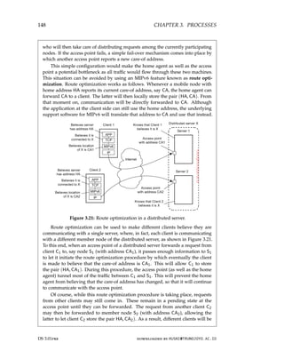
![3.4. SERVERS 149
directly communicating with different members of the distributed server, where
each client application still has the illusion that this server has address HA. The
home agent continues to communicate with the access point talking to the contact
address.
Case study: PlanetLab
Let us now take a closer look at a somewhat unusual cluster server. PlanetLab
is a collaborative distributed system in which different organizations each
donate one or more computers, adding up to a total of hundreds of nodes.
Together, these computers form a 1-tier server cluster, where access, processing,
and storage can all take place on each node individually. Management of
PlanetLab is by necessity almost entirely distributed.
General organization In PlanetLab, a participating organization donates
one or more nodes (i.e., computers) that are subsequently shared among all
PlanetLab users. Each node is organized as shown in Figure 3.22. There
are two important components [Bavier et al., 2004; Peterson et al., 2006].
The first one is the virtual machine monitor (VMM), which is an enhanced
Linux operating system. The enhancements mainly comprise adjustments
for supporting the second component, namely (Linux) Vservers. For now, a
Vserver can best be thought of as a separate environment in which a group of
processes run. We return to Vservers below.
Figure 3.22: The basic organization of a PlanetLab node.
The Linux VMM ensures that Vservers are separated: processes in different
Vservers are executed concurrently and independently, each making use only
of the software packages and programs available in their own environment.
downloaded by HUSNI@TRUNOJOYO.AC.ID DS 3.01pre
3.4. SERVERS 149
directly communicating with different members of the distributed server, where
each client application still has the illusion that this server has address HA. The
home agent continues to communicate with the access point talking to the contact
address.
Case study: PlanetLab
Let us now take a closer look at a somewhat unusual cluster server. PlanetLab
is a collaborative distributed system in which different organizations each
donate one or more computers, adding up to a total of hundreds of nodes.
Together, these computers form a 1-tier server cluster, where access, processing,
and storage can all take place on each node individually. Management of
PlanetLab is by necessity almost entirely distributed.
General organization In PlanetLab, a participating organization donates
one or more nodes (i.e., computers) that are subsequently shared among all
PlanetLab users. Each node is organized as shown in Figure 3.22. There
are two important components [Bavier et al., 2004; Peterson et al., 2006].
The first one is the virtual machine monitor (VMM), which is an enhanced
Linux operating system. The enhancements mainly comprise adjustments
for supporting the second component, namely (Linux) Vservers. For now, a
Vserver can best be thought of as a separate environment in which a group of
processes run. We return to Vservers below.
Figure 3.22: The basic organization of a PlanetLab node.
The Linux VMM ensures that Vservers are separated: processes in different
Vservers are executed concurrently and independently, each making use only
of the software packages and programs available in their own environment.
downloaded by HUSNI@TRUNOJOYO.AC.ID DS 3.01pre](https://image.slidesharecdn.com/distributed-systems-3rd-edition-251215232331-7e034da0/85/architectureec-distributed-systems-3rd-Edition-pdf-163-320.jpg)
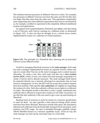
![3.4. SERVERS 151
Resources are bound to slices. In other words, in order to make use of
resources, it is necessary to create a slice. Each slice is associated with a
service provider, which can best be seen as an entity having an account
on PlanetLab. Every slice can then be identified by a (principal_id, slice_tag)
pair, where the principal_id identifies the provider and slice_tag is an identifier
chosen by the provider.
Vservers Let us now turn our attention to PlanetLab’s Vservers, which have
been described and evaluated by Soltesz et al. [2007]. A Vserver is organized
according to what is called a container-based approach. The main difference
with traditional virtual machines as those discussed in Section 3.2, is that they
rely on a single, shared operating-system kernel. This also means that resource
management is mostly done only by the underlying operating system and not
by any of the Vservers. The primary task of a Vserver is therefore to merely
support a group of processes and keep that group isolated from processes
running under the jurisdiction of another Vserver. Indeed, a Vserver forms an
isolated container for a group of processes and their allocated resources. By
now, containers have become quite popular for offering cloud services.
This isolation is technically established by the underlying VMM, for which
purpose the Linux operating system has been adapted. One of the most
salient adaptations concerns the separation of independent name spaces. For
example, to create the illusion that a Vserver is really a single machine, the
Unix process init traditionally always gets process ID 1 (with its parent having
ID 0). Obviously, the Linux VMM will already have such a process running,
yet it needs to create another init process for every Vserver. Those processes
will each also get process ID 1, while the kernel keeps track of a mapping
between such a virtual process ID and the real, actually assigned process ID.
Other examples of consistent naming across Vservers easily come to mind.
Likewise, isolation is also established by providing each Vserver with
its own set of libraries, yet using the directory structure that those libraries
expect, that is, with directories named /dev, /home, /proc, /usr, and so on
(which is also depicted in Figure 3.22). In principle, such a separated name
space can be achieved using the standard chroot command, effectively giving
each Vserver its own root directory. However, special measures are needed at
kernel level to prevent unauthorized access of one Vserver to the directory
tree of another Vserver, as explained by Soltesz et al. [2007].
An important advantage of the container-based approach toward virtual-
ization in comparison to running separate guest operating systems, is that
resource allocation can generally be much simpler. In particular, it is possible
to overbook resources by allowing for dynamic resource allocation, just as is
done with allocating resources to normal processes. Normally, when using
a guest operating system, the guest will have to be allocated a fixed amount
of resources in advance (notably main memory). When considering that the
downloaded by HUSNI@TRUNOJOYO.AC.ID DS 3.01pre
3.4. SERVERS 151
Resources are bound to slices. In other words, in order to make use of
resources, it is necessary to create a slice. Each slice is associated with a
service provider, which can best be seen as an entity having an account
on PlanetLab. Every slice can then be identified by a (principal_id, slice_tag)
pair, where the principal_id identifies the provider and slice_tag is an identifier
chosen by the provider.
Vservers Let us now turn our attention to PlanetLab’s Vservers, which have
been described and evaluated by Soltesz et al. [2007]. A Vserver is organized
according to what is called a container-based approach. The main difference
with traditional virtual machines as those discussed in Section 3.2, is that they
rely on a single, shared operating-system kernel. This also means that resource
management is mostly done only by the underlying operating system and not
by any of the Vservers. The primary task of a Vserver is therefore to merely
support a group of processes and keep that group isolated from processes
running under the jurisdiction of another Vserver. Indeed, a Vserver forms an
isolated container for a group of processes and their allocated resources. By
now, containers have become quite popular for offering cloud services.
This isolation is technically established by the underlying VMM, for which
purpose the Linux operating system has been adapted. One of the most
salient adaptations concerns the separation of independent name spaces. For
example, to create the illusion that a Vserver is really a single machine, the
Unix process init traditionally always gets process ID 1 (with its parent having
ID 0). Obviously, the Linux VMM will already have such a process running,
yet it needs to create another init process for every Vserver. Those processes
will each also get process ID 1, while the kernel keeps track of a mapping
between such a virtual process ID and the real, actually assigned process ID.
Other examples of consistent naming across Vservers easily come to mind.
Likewise, isolation is also established by providing each Vserver with
its own set of libraries, yet using the directory structure that those libraries
expect, that is, with directories named /dev, /home, /proc, /usr, and so on
(which is also depicted in Figure 3.22). In principle, such a separated name
space can be achieved using the standard chroot command, effectively giving
each Vserver its own root directory. However, special measures are needed at
kernel level to prevent unauthorized access of one Vserver to the directory
tree of another Vserver, as explained by Soltesz et al. [2007].
An important advantage of the container-based approach toward virtual-
ization in comparison to running separate guest operating systems, is that
resource allocation can generally be much simpler. In particular, it is possible
to overbook resources by allowing for dynamic resource allocation, just as is
done with allocating resources to normal processes. Normally, when using
a guest operating system, the guest will have to be allocated a fixed amount
of resources in advance (notably main memory). When considering that the
downloaded by HUSNI@TRUNOJOYO.AC.ID DS 3.01pre](https://image.slidesharecdn.com/distributed-systems-3rd-edition-251215232331-7e034da0/85/architectureec-distributed-systems-3rd-Edition-pdf-165-320.jpg)
![152 CHAPTER 3. PROCESSES
nodes provided by participating PlanetLab organizations are required to have
only few GByte of main memory, it is not hard to imagine that memory
may be a scarce resource. It is therefore necessary to dynamically allocate
memory to allow tens of virtual machines to be running at the same time
on a single node. Vservers are ideal for this type of resource management;
operating systems are much harder to support in such cases. Of course, this
cannot prevent a Vserver from using too much memory on a busy node. The
PlanetLab policy in that case is simple: the Vserver hogging memory when
swap space is almost filled, is reset.
3.5 Code migration
So far, we have been mainly concerned with distributed systems in which
communication is limited to passing data. However, there are situations
in which passing programs, sometimes even while they are being executed,
simplifies the design of a distributed system. In this section, we take a detailed
look at what code migration actually is. We start by considering different
approaches to code migration, followed by a discussion on how to deal with
the local resources that a migrating program uses. A particularly hard problem
is migrating code in heterogeneous systems, which is also discussed.
Reasons for migrating code
Traditionally, code migration in distributed systems took place in the form
of process migration in which an entire process was moved from one node
to another [Milojicic et al., 2000]. Moving a running process to a different
machine is a costly and intricate task, and there had better be a good reason
for doing so. That reason has always been performance. The basic idea is
that overall system performance can be improved if processes are moved from
heavily loaded to lightly loaded machines. Load is often expressed in terms
of the CPU queue length or CPU utilization, but other performance indicators
are used as well. When completing their survey, Milojicic et al. had already
come to the conclusion that process migration was no longer a viable option
for improving distributed systems.
However, instead of offloading machines, we can now witness that code
is moved to make sure that a machine is sufficiently loaded. In particular,
migrating complete virtual machines with their suite of applications to lightly
loaded machines in order to minimize the total number of nodes being used
is common practice in optimizing energy usage in data centers. Interestingly
enough, although migrating virtual machines may require more resources,
the task itself is far less intricate than migrating a process, as we discuss in
Note 3.11.
In general, load-distribution algorithms by which decisions are made con-
cerning the allocation and redistribution of tasks with respect to a set of
DS 3.01pre downloaded by HUSNI@TRUNOJOYO.AC.ID
152 CHAPTER 3. PROCESSES
nodes provided by participating PlanetLab organizations are required to have
only few GByte of main memory, it is not hard to imagine that memory
may be a scarce resource. It is therefore necessary to dynamically allocate
memory to allow tens of virtual machines to be running at the same time
on a single node. Vservers are ideal for this type of resource management;
operating systems are much harder to support in such cases. Of course, this
cannot prevent a Vserver from using too much memory on a busy node. The
PlanetLab policy in that case is simple: the Vserver hogging memory when
swap space is almost filled, is reset.
3.5 Code migration
So far, we have been mainly concerned with distributed systems in which
communication is limited to passing data. However, there are situations
in which passing programs, sometimes even while they are being executed,
simplifies the design of a distributed system. In this section, we take a detailed
look at what code migration actually is. We start by considering different
approaches to code migration, followed by a discussion on how to deal with
the local resources that a migrating program uses. A particularly hard problem
is migrating code in heterogeneous systems, which is also discussed.
Reasons for migrating code
Traditionally, code migration in distributed systems took place in the form
of process migration in which an entire process was moved from one node
to another [Milojicic et al., 2000]. Moving a running process to a different
machine is a costly and intricate task, and there had better be a good reason
for doing so. That reason has always been performance. The basic idea is
that overall system performance can be improved if processes are moved from
heavily loaded to lightly loaded machines. Load is often expressed in terms
of the CPU queue length or CPU utilization, but other performance indicators
are used as well. When completing their survey, Milojicic et al. had already
come to the conclusion that process migration was no longer a viable option
for improving distributed systems.
However, instead of offloading machines, we can now witness that code
is moved to make sure that a machine is sufficiently loaded. In particular,
migrating complete virtual machines with their suite of applications to lightly
loaded machines in order to minimize the total number of nodes being used
is common practice in optimizing energy usage in data centers. Interestingly
enough, although migrating virtual machines may require more resources,
the task itself is far less intricate than migrating a process, as we discuss in
Note 3.11.
In general, load-distribution algorithms by which decisions are made con-
cerning the allocation and redistribution of tasks with respect to a set of
DS 3.01pre downloaded by HUSNI@TRUNOJOYO.AC.ID](https://image.slidesharecdn.com/distributed-systems-3rd-edition-251215232331-7e034da0/85/architectureec-distributed-systems-3rd-Edition-pdf-166-320.jpg)
![3.5. CODE MIGRATION 153
machines, play an important role in compute-intensive systems. However, in
many modern distributed systems, optimizing computing capacity is less an
issue than, for example, trying to minimize communication. Moreover, due to
the heterogeneity of the underlying platforms and computer networks, per-
formance improvement through code migration is often based on qualitative
reasoning instead of mathematical models.
Consider, as an example, a client-server system in which the server man-
ages a huge database. If a client application needs to perform many database
operations involving large quantities of data, it may be better to ship part
of the client application to the server and send only the results across the
network. Otherwise, the network may be swamped with the transfer of data
from the server to the client. In this case, code migration is based on the
assumption that it generally makes sense to process data close to where those
data reside.
This same reason can be used for migrating parts of the server to the client.
For example, in many interactive database applications, clients need to fill in
forms that are subsequently translated into a series of database operations.
Processing the form at the client side, and sending only the completed form
to the server, can sometimes avoid that a relatively large number of small
messages need to cross the network. The result is that the client perceives
better performance, while at the same time the server spends less time on
form processing and communication. In the case of smartphones, moving
code to be executed at the handheld instead of the server may be the only
viable solution to obtain acceptable performance, both for the client and the
server (see Kumar et al. [2013] for a survey on offloading computations).
Support for code migration can also help improve performance by ex-
ploiting parallelism, but without the usual intricacies related to parallel pro-
gramming. A typical example is searching for information in the Web. It is
relatively simple to implement a search query in the form of a small mobile
program, called a mobile agent, that moves from site to site. By making
several copies of such a program, and sending each off to different sites, we
may be able to achieve a linear speed-up compared to using just a single
program instance. However, Carzaniga et al. [2007] conclude that mobile
agents have never become successful because they did not really offer an
obvious advantage over other technologies. Moreover, and crucial, it turned
out to be virtually impossible to let this type of mobile code operate in a
secure way.
Besides improving performance, there are other reasons for supporting
code migration as well. The most important one is that of flexibility. The
traditional approach to building distributed applications is to partition the
application into different parts, and decide in advance where each part should
be executed. This approach, for example, has lead to different multitiered
client-server applications discussed in Section 2.3.
downloaded by HUSNI@TRUNOJOYO.AC.ID DS 3.01pre
3.5. CODE MIGRATION 153
machines, play an important role in compute-intensive systems. However, in
many modern distributed systems, optimizing computing capacity is less an
issue than, for example, trying to minimize communication. Moreover, due to
the heterogeneity of the underlying platforms and computer networks, per-
formance improvement through code migration is often based on qualitative
reasoning instead of mathematical models.
Consider, as an example, a client-server system in which the server man-
ages a huge database. If a client application needs to perform many database
operations involving large quantities of data, it may be better to ship part
of the client application to the server and send only the results across the
network. Otherwise, the network may be swamped with the transfer of data
from the server to the client. In this case, code migration is based on the
assumption that it generally makes sense to process data close to where those
data reside.
This same reason can be used for migrating parts of the server to the client.
For example, in many interactive database applications, clients need to fill in
forms that are subsequently translated into a series of database operations.
Processing the form at the client side, and sending only the completed form
to the server, can sometimes avoid that a relatively large number of small
messages need to cross the network. The result is that the client perceives
better performance, while at the same time the server spends less time on
form processing and communication. In the case of smartphones, moving
code to be executed at the handheld instead of the server may be the only
viable solution to obtain acceptable performance, both for the client and the
server (see Kumar et al. [2013] for a survey on offloading computations).
Support for code migration can also help improve performance by ex-
ploiting parallelism, but without the usual intricacies related to parallel pro-
gramming. A typical example is searching for information in the Web. It is
relatively simple to implement a search query in the form of a small mobile
program, called a mobile agent, that moves from site to site. By making
several copies of such a program, and sending each off to different sites, we
may be able to achieve a linear speed-up compared to using just a single
program instance. However, Carzaniga et al. [2007] conclude that mobile
agents have never become successful because they did not really offer an
obvious advantage over other technologies. Moreover, and crucial, it turned
out to be virtually impossible to let this type of mobile code operate in a
secure way.
Besides improving performance, there are other reasons for supporting
code migration as well. The most important one is that of flexibility. The
traditional approach to building distributed applications is to partition the
application into different parts, and decide in advance where each part should
be executed. This approach, for example, has lead to different multitiered
client-server applications discussed in Section 2.3.
downloaded by HUSNI@TRUNOJOYO.AC.ID DS 3.01pre](https://image.slidesharecdn.com/distributed-systems-3rd-edition-251215232331-7e034da0/85/architectureec-distributed-systems-3rd-Edition-pdf-167-320.jpg)
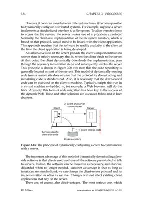
![3.5. CODE MIGRATION 155
we discuss in Chapter 9, has to do with security. Blindly trusting that the
downloaded code implements only the advertised interface while accessing
your unprotected hard disk and does not send the juiciest parts to heaven-
knows-who may not always be such a good idea. Fortunately, it is well
understood how to protect the client against malicious, downloaded code.
Note 3.10 (More information: Moving away from thin-client computing?)
By now, there is much more insight and expertise concerning transparent and
safe dynamic migration of code to clients. As a result, the trend that we described
in Note 2.4 of moving toward thin-client computing because managing client-
side software often turned out to be cumbersome, has been partly reverted.
By dynamically migrating client-side software, yet keeping the management of
that software entirely at the server side (or rather, at its owner), having “richer”
client-side software has become practically feasible.
Note 3.11 (Advanced: Models for code migration)
Although code migration suggests that we move only code between machines,
the term actually covers a much richer area. Traditionally, communication in
distributed systems is concerned with exchanging data between processes. Code
migration in the broadest sense deals with moving programs between machines,
with the intention to have those programs be executed at the target. In some cases,
as in process migration, the execution status of a program, pending signals, and
other parts of the environment must be moved as well.
To get a better understanding of the different models for code migration, we
use a framework proposed by Fuggetta et al. [1998]. In this framework, a process
consists of three segments. The code segment is the part that contains the set
of instructions that make up the program that is being executed. The resource
segment contains references to external resources needed by the process, such as
files, printers, devices, other processes, and so on. Finally, an execution segment
is used to store the current execution state of a process, consisting of private data,
the stack, and, of course, the program counter.
A further distinction can be made between sender-initiated and receiver-
initiated migration. In sender-initiated migration, migration is initiated at the
machine where the code currently resides or is being executed. Typically, sender-
initiated migration is done when uploading programs to a compute server. An-
other example is sending a query, or batch of queries, to a remote database server.
In receiver-initiated migration, the initiative for code migration is taken by the
target machine. Java applets are an example of this approach.
Receiver-initiated migration is simpler than sender-initiated migration. In
many cases, code migration occurs between a client and a server, where the client
takes the initiative for migration. Securely uploading code to a server, as is done
in sender-initiated migration, often requires that the client has previously been
registered and authenticated at that server. In other words, the server is required
to know all its clients, the reason being is that the client will presumably want
downloaded by HUSNI@TRUNOJOYO.AC.ID DS 3.01pre
3.5. CODE MIGRATION 155
we discuss in Chapter 9, has to do with security. Blindly trusting that the
downloaded code implements only the advertised interface while accessing
your unprotected hard disk and does not send the juiciest parts to heaven-
knows-who may not always be such a good idea. Fortunately, it is well
understood how to protect the client against malicious, downloaded code.
Note 3.10 (More information: Moving away from thin-client computing?)
By now, there is much more insight and expertise concerning transparent and
safe dynamic migration of code to clients. As a result, the trend that we described
in Note 2.4 of moving toward thin-client computing because managing client-
side software often turned out to be cumbersome, has been partly reverted.
By dynamically migrating client-side software, yet keeping the management of
that software entirely at the server side (or rather, at its owner), having “richer”
client-side software has become practically feasible.
Note 3.11 (Advanced: Models for code migration)
Although code migration suggests that we move only code between machines,
the term actually covers a much richer area. Traditionally, communication in
distributed systems is concerned with exchanging data between processes. Code
migration in the broadest sense deals with moving programs between machines,
with the intention to have those programs be executed at the target. In some cases,
as in process migration, the execution status of a program, pending signals, and
other parts of the environment must be moved as well.
To get a better understanding of the different models for code migration, we
use a framework proposed by Fuggetta et al. [1998]. In this framework, a process
consists of three segments. The code segment is the part that contains the set
of instructions that make up the program that is being executed. The resource
segment contains references to external resources needed by the process, such as
files, printers, devices, other processes, and so on. Finally, an execution segment
is used to store the current execution state of a process, consisting of private data,
the stack, and, of course, the program counter.
A further distinction can be made between sender-initiated and receiver-
initiated migration. In sender-initiated migration, migration is initiated at the
machine where the code currently resides or is being executed. Typically, sender-
initiated migration is done when uploading programs to a compute server. An-
other example is sending a query, or batch of queries, to a remote database server.
In receiver-initiated migration, the initiative for code migration is taken by the
target machine. Java applets are an example of this approach.
Receiver-initiated migration is simpler than sender-initiated migration. In
many cases, code migration occurs between a client and a server, where the client
takes the initiative for migration. Securely uploading code to a server, as is done
in sender-initiated migration, often requires that the client has previously been
registered and authenticated at that server. In other words, the server is required
to know all its clients, the reason being is that the client will presumably want
downloaded by HUSNI@TRUNOJOYO.AC.ID DS 3.01pre](https://image.slidesharecdn.com/distributed-systems-3rd-edition-251215232331-7e034da0/85/architectureec-distributed-systems-3rd-Edition-pdf-169-320.jpg)
![156 CHAPTER 3. PROCESSES
access to the server’s resources such as its disk. Protecting such resources is
essential. In contrast, downloading code as in the receiver-initiated case, can often
be done anonymously. Moreover, the server is generally not interested in the
client’s resources. Instead, code migration to the client is done only for improving
client-side performance. To that end, only a limited number of resources need to
be protected, such as memory and network connections. We return to secure code
migration extensively in Chapter 9.
Before execution After execution
Client Server Client Server
CS
code
exec
resource
code
exec*
resource
REV
code
−→ exec
resource
−→
code
exec*
resource
CoD exec
resource
←−
code code
exec*
resource
←−
MA
code
exec
resource
−→
resource resource
−→
code
exec*
resource
CS: Client-Server REV: Remote evaluation
CoD: Code-on-demand MA: Mobile agents
Figure 3.25: Four different paradigms for code mobility.
This brings us to four different paradigms for code mobility, as shown in
Figure 3.25. Following Fuggetta et al. [1998], we make a distinction between sim-
ple client-server computing, remote evaluation, code-on-demand, and mobile
agents. Figure 3.25 shows the situation at respectively the client and the server,
before and after execution of the mobile code.
In the case of client-server computing, the code, execution state, and resource
segment are all located at the server, and after execution, only the execution state
at the server is generally modified. This state modification is denoted by means
of an asterisk. With the sender-initiated remote evaluation, the client migrates
code to the server where that code is executed and leading to a modification of
the execution state at the server. Code-on-demand is a receiver-initiated scheme
by which the client obtains code from the server with its execution modifying
DS 3.01pre downloaded by HUSNI@TRUNOJOYO.AC.ID
156 CHAPTER 3. PROCESSES
access to the server’s resources such as its disk. Protecting such resources is
essential. In contrast, downloading code as in the receiver-initiated case, can often
be done anonymously. Moreover, the server is generally not interested in the
client’s resources. Instead, code migration to the client is done only for improving
client-side performance. To that end, only a limited number of resources need to
be protected, such as memory and network connections. We return to secure code
migration extensively in Chapter 9.
Before execution After execution
Client Server Client Server
CS
code
exec
resource
code
exec*
resource
REV
code
−→ exec
resource
−→
code
exec*
resource
CoD exec
resource
←−
code code
exec*
resource
←−
MA
code
exec
resource
−→
resource resource
−→
code
exec*
resource
CS: Client-Server REV: Remote evaluation
CoD: Code-on-demand MA: Mobile agents
Figure 3.25: Four different paradigms for code mobility.
This brings us to four different paradigms for code mobility, as shown in
Figure 3.25. Following Fuggetta et al. [1998], we make a distinction between sim-
ple client-server computing, remote evaluation, code-on-demand, and mobile
agents. Figure 3.25 shows the situation at respectively the client and the server,
before and after execution of the mobile code.
In the case of client-server computing, the code, execution state, and resource
segment are all located at the server, and after execution, only the execution state
at the server is generally modified. This state modification is denoted by means
of an asterisk. With the sender-initiated remote evaluation, the client migrates
code to the server where that code is executed and leading to a modification of
the execution state at the server. Code-on-demand is a receiver-initiated scheme
by which the client obtains code from the server with its execution modifying
DS 3.01pre downloaded by HUSNI@TRUNOJOYO.AC.ID](https://image.slidesharecdn.com/distributed-systems-3rd-edition-251215232331-7e034da0/85/architectureec-distributed-systems-3rd-Edition-pdf-170-320.jpg)
![158 CHAPTER 3. PROCESSES
Migration in heterogeneous systems
So far, we have tacitly assumed that the migrated code can be easily executed
at the target machine. This assumption is in order when dealing with homo-
geneous systems. In general, however, distributed systems are constructed
on a heterogeneous collection of platforms, each having their own operating
system and machine architecture.
The problems coming from heterogeneity are in many respects the same
as those of portability. Not surprisingly, solutions are also very similar. For
example, at the end of the 1970s, a simple solution to alleviate many of the
problems of porting Pascal to different machines was to generate machine-
independent intermediate code for an abstract virtual machine [Barron, 1981].
That machine, of course, would need to be implemented on many platforms,
but it would then allow Pascal programs to be run anywhere. Although this
simple idea was widely used for some years, it never really caught on as the
general solution to portability problems for other languages, notably C.
About 25 years later, code migration in heterogeneous systems is being
tackled by scripting languages and highly portable languages such as Java.
In essence, these solutions adopt the same approach as was done for porting
Pascal. All such solutions have in common that they rely on a (process) virtual
machine that either directly interprets source code (as in the case of scripting
languages), or otherwise interprets intermediate code generated by a compiler
(as in Java). Being in the right place at the right time is also important for
language developers.
Further developments have weakened the dependency on programming
languages. In particular, solutions have been proposed to migrate not only
processes, but to migrate entire computing environments. The basic idea
is to compartmentalize the overall environment and to provide processes
in the same part their own view on their computing environment. That
compartmentalization takes place in the form of virtual machine monitors
running an operating system and a suite of applications.
With virtual machine migration, it becomes possible to decouple a com-
puting environment from the underlying system and actually migrate it to
another machine. A major advantage of this approach is that processes can
remain ignorant of the migration itself: they need not be interrupted in their
execution, nor should they experience any problems with used resources. The
latter are either migrating along with a process, or the way that a process
accesses a resource is left unaffected (at least, for that process).
As an example, Clark et al. [2005] concentrated on real-time migration of a
virtualized operating system, typically something that would be convenient
in a cluster of servers where a tight coupling is achieved through a single,
shared local-area network. Under these circumstances, migration involves two
major problems: migrating the entire memory image and migrating bindings
to local resources.
DS 3.01pre downloaded by HUSNI@TRUNOJOYO.AC.ID
158 CHAPTER 3. PROCESSES
Migration in heterogeneous systems
So far, we have tacitly assumed that the migrated code can be easily executed
at the target machine. This assumption is in order when dealing with homo-
geneous systems. In general, however, distributed systems are constructed
on a heterogeneous collection of platforms, each having their own operating
system and machine architecture.
The problems coming from heterogeneity are in many respects the same
as those of portability. Not surprisingly, solutions are also very similar. For
example, at the end of the 1970s, a simple solution to alleviate many of the
problems of porting Pascal to different machines was to generate machine-
independent intermediate code for an abstract virtual machine [Barron, 1981].
That machine, of course, would need to be implemented on many platforms,
but it would then allow Pascal programs to be run anywhere. Although this
simple idea was widely used for some years, it never really caught on as the
general solution to portability problems for other languages, notably C.
About 25 years later, code migration in heterogeneous systems is being
tackled by scripting languages and highly portable languages such as Java.
In essence, these solutions adopt the same approach as was done for porting
Pascal. All such solutions have in common that they rely on a (process) virtual
machine that either directly interprets source code (as in the case of scripting
languages), or otherwise interprets intermediate code generated by a compiler
(as in Java). Being in the right place at the right time is also important for
language developers.
Further developments have weakened the dependency on programming
languages. In particular, solutions have been proposed to migrate not only
processes, but to migrate entire computing environments. The basic idea
is to compartmentalize the overall environment and to provide processes
in the same part their own view on their computing environment. That
compartmentalization takes place in the form of virtual machine monitors
running an operating system and a suite of applications.
With virtual machine migration, it becomes possible to decouple a com-
puting environment from the underlying system and actually migrate it to
another machine. A major advantage of this approach is that processes can
remain ignorant of the migration itself: they need not be interrupted in their
execution, nor should they experience any problems with used resources. The
latter are either migrating along with a process, or the way that a process
accesses a resource is left unaffected (at least, for that process).
As an example, Clark et al. [2005] concentrated on real-time migration of a
virtualized operating system, typically something that would be convenient
in a cluster of servers where a tight coupling is achieved through a single,
shared local-area network. Under these circumstances, migration involves two
major problems: migrating the entire memory image and migrating bindings
to local resources.
DS 3.01pre downloaded by HUSNI@TRUNOJOYO.AC.ID](https://image.slidesharecdn.com/distributed-systems-3rd-edition-251215232331-7e034da0/85/architectureec-distributed-systems-3rd-Edition-pdf-172-320.jpg)
![3.5. CODE MIGRATION 159
As to the first problem, there are, in principle, three ways to handle
migration (which can be combined):
1. Pushing memory pages to the new machine and resending the ones that
are later modified during the migration process.
2. Stopping the current virtual machine; migrate memory, and start the
new virtual machine.
3. Letting the new virtual machine pull in new pages as needed, that is,
let processes start on the new virtual machine immediately and copy
memory pages on demand.
The second option may lead to unacceptable downtime if the migrating
virtual machine is running a live service, that is, one that offers continuous
service. On the other hand, a pure on-demand approach as represented by
the third option may extensively prolong the migration period, but may also
lead to poor performance because it takes a long time before the working set
of the migrated processes has been moved to the new machine.
As an alternative, Clark et al. [2005] propose to use a pre-copy approach
which combines the first option, along with a brief stop-and-copy phase as
represented by the second option. As it turns out, this combination can lead
to very low service downtimes (see also Note 3.12).
Concerning local resources, matters are simplified when dealing only with
a cluster server. First, because there is a single network, the only thing that
needs to be done is to announce the new network-to-MAC address binding, so
that clients can contact the migrated processes at the correct network interface.
Finally, if it can be assumed that storage is provided as a separate tier (like we
showed in Figure 3.18), then migrating binding to files is similarly simple, as
it effectively means reestablishing network connections.
Note 3.12 (Advanced: On the performance of live virtual machine migration)
One potential problem with virtual-machine migration is that it may take consid-
erable time. This by itself need not be bad as long as the services that are running
on the migrating virtual machine can continue to operate. An approach used in
practice was briefly described above. First, memory pages are copied to the target
machine, possibly sending updates of pages that were modified while copying
took place (remember that copying lots of memory may take tens of seconds, even
across a high-speed local network). Second, when most pages have been faithfully
copied, the current machine is stopped, the remaining dirty pages are copied to
the target, where the now exact copy can then be started where the original left
off.
The downtime in which the remaining dirty pages need to be copied depends
on the applications running on the virtual machine. Clark et al. [2005] report
downtimes for specific configurations between 60 msecs and less than 4 secs.
Voorsluys et al. [2009] come to similar values. However, what may be more
downloaded by HUSNI@TRUNOJOYO.AC.ID DS 3.01pre
3.5. CODE MIGRATION 159
As to the first problem, there are, in principle, three ways to handle
migration (which can be combined):
1. Pushing memory pages to the new machine and resending the ones that
are later modified during the migration process.
2. Stopping the current virtual machine; migrate memory, and start the
new virtual machine.
3. Letting the new virtual machine pull in new pages as needed, that is,
let processes start on the new virtual machine immediately and copy
memory pages on demand.
The second option may lead to unacceptable downtime if the migrating
virtual machine is running a live service, that is, one that offers continuous
service. On the other hand, a pure on-demand approach as represented by
the third option may extensively prolong the migration period, but may also
lead to poor performance because it takes a long time before the working set
of the migrated processes has been moved to the new machine.
As an alternative, Clark et al. [2005] propose to use a pre-copy approach
which combines the first option, along with a brief stop-and-copy phase as
represented by the second option. As it turns out, this combination can lead
to very low service downtimes (see also Note 3.12).
Concerning local resources, matters are simplified when dealing only with
a cluster server. First, because there is a single network, the only thing that
needs to be done is to announce the new network-to-MAC address binding, so
that clients can contact the migrated processes at the correct network interface.
Finally, if it can be assumed that storage is provided as a separate tier (like we
showed in Figure 3.18), then migrating binding to files is similarly simple, as
it effectively means reestablishing network connections.
Note 3.12 (Advanced: On the performance of live virtual machine migration)
One potential problem with virtual-machine migration is that it may take consid-
erable time. This by itself need not be bad as long as the services that are running
on the migrating virtual machine can continue to operate. An approach used in
practice was briefly described above. First, memory pages are copied to the target
machine, possibly sending updates of pages that were modified while copying
took place (remember that copying lots of memory may take tens of seconds, even
across a high-speed local network). Second, when most pages have been faithfully
copied, the current machine is stopped, the remaining dirty pages are copied to
the target, where the now exact copy can then be started where the original left
off.
The downtime in which the remaining dirty pages need to be copied depends
on the applications running on the virtual machine. Clark et al. [2005] report
downtimes for specific configurations between 60 msecs and less than 4 secs.
Voorsluys et al. [2009] come to similar values. However, what may be more
downloaded by HUSNI@TRUNOJOYO.AC.ID DS 3.01pre](https://image.slidesharecdn.com/distributed-systems-3rd-edition-251215232331-7e034da0/85/architectureec-distributed-systems-3rd-Edition-pdf-173-320.jpg)
![160 CHAPTER 3. PROCESSES
interesting is to observe what the response time is of the service running on the
virtual machine while the latter is being migrated. The model in this case is
that the service continues to operate on the original machine until full migration
has completed. However, we cannot ignore that migration itself is resource-
intensive operation, requiring considerable processing capacity as well as network
bandwidth.
Figure 3.26: The effect on the response time of a service while migrating
its underlying virtual machine. Adapted from Voorsluys et al. [2009].
Voorsluys et al. [2009] have observed that a complete migration may actually
take tens of seconds, leading to a ten- to twentyfold increase in response time. In
addition, we need to realize that during the migration, a service will be completely
unavailable (i.e., unresponsive) for perhaps 4 seconds. The good news is that
the response time goes up significantly only after the downtime to complete the
migration, as shown in Figure 3.26.
In many cases, virtual machines are migrated to optimize the usage of actual
machines. However, it may also be desirable to clone a virtual machine, for
example, because the workload for the current machine is becoming too high.
Such cloning is very similar to using multiple processes in concurrent servers by
which a dispatcher process creates worker processes to handle incoming requests.
This scheme was explained in Figure 3.4 when discussing multithreaded servers.
When cloning for this type of performance, it often makes more sense not to
first copy memory pages, but, in fact, start with as few pages as possible as the
service running on the cloned machine will essentially start anew. Note that this
behavior is very similar to the usual parent-child behavior we see when forking a
Unix process. Namely, the child will start with loading its own executable, thereby
effectively cleaning the memory it inherited from its parent. This analogy inspired
Lagar-Cavilla et al. [2009] to develop an analogous mechanism for forking a virtual
machine. However, unlike the mechanism used traditionally for migrating virtual
machines, their VM fork copies pages primarily on demand. The result is an
extremely efficient cloning mechanism.
It is thus seen that there is no single best way to place copies of a virtual
machine on different physical machines: it very much depends on how and why
a virtual machine is being deployed.
DS 3.01pre downloaded by HUSNI@TRUNOJOYO.AC.ID
160 CHAPTER 3. PROCESSES
interesting is to observe what the response time is of the service running on the
virtual machine while the latter is being migrated. The model in this case is
that the service continues to operate on the original machine until full migration
has completed. However, we cannot ignore that migration itself is resource-
intensive operation, requiring considerable processing capacity as well as network
bandwidth.
Figure 3.26: The effect on the response time of a service while migrating
its underlying virtual machine. Adapted from Voorsluys et al. [2009].
Voorsluys et al. [2009] have observed that a complete migration may actually
take tens of seconds, leading to a ten- to twentyfold increase in response time. In
addition, we need to realize that during the migration, a service will be completely
unavailable (i.e., unresponsive) for perhaps 4 seconds. The good news is that
the response time goes up significantly only after the downtime to complete the
migration, as shown in Figure 3.26.
In many cases, virtual machines are migrated to optimize the usage of actual
machines. However, it may also be desirable to clone a virtual machine, for
example, because the workload for the current machine is becoming too high.
Such cloning is very similar to using multiple processes in concurrent servers by
which a dispatcher process creates worker processes to handle incoming requests.
This scheme was explained in Figure 3.4 when discussing multithreaded servers.
When cloning for this type of performance, it often makes more sense not to
first copy memory pages, but, in fact, start with as few pages as possible as the
service running on the cloned machine will essentially start anew. Note that this
behavior is very similar to the usual parent-child behavior we see when forking a
Unix process. Namely, the child will start with loading its own executable, thereby
effectively cleaning the memory it inherited from its parent. This analogy inspired
Lagar-Cavilla et al. [2009] to develop an analogous mechanism for forking a virtual
machine. However, unlike the mechanism used traditionally for migrating virtual
machines, their VM fork copies pages primarily on demand. The result is an
extremely efficient cloning mechanism.
It is thus seen that there is no single best way to place copies of a virtual
machine on different physical machines: it very much depends on how and why
a virtual machine is being deployed.
DS 3.01pre downloaded by HUSNI@TRUNOJOYO.AC.ID](https://image.slidesharecdn.com/distributed-systems-3rd-edition-251215232331-7e034da0/85/architectureec-distributed-systems-3rd-Edition-pdf-174-320.jpg)
![164 CHAPTER 4. COMMUNICATION
again due to their lack of distribution transparency. An alternative is to use a
high-level message-queuing model, in which communication proceeds much
the same as in e-mail systems. Message-oriented communication is a subject
important enough to warrant a section of its own. We look at numerous
aspects, including application-level routing.
Finally, since our understanding of setting up multicast facilities has im-
proved, novel and elegant solutions for data dissemination have emerged.
We pay separate attention to this subject in the last section of this chapter,
discussing traditional deterministic means of multicasting, as well as proba-
bilistic approaches as used in flooding and gossiping. The latter have been
receiving increased attention over the past years due to their elegance and
simplicity.
4.1 Foundations
Before we start our discussion on communication in distributed systems, we
first recapitulate some of the fundamental issues related to communication.
In the next section we briefly discuss network communication protocols, as
these form the basis for any distributed system. After that, we take a different
approach by classifying the different types of communication that usually
occur in distributed systems.
Layered Protocols
Due to the absence of shared memory, all communication in distributed
systems is based on sending and receiving (low level) messages. When
process P wants to communicate with process Q, it first builds a message in
its own address space. Then it executes a system call that causes the operating
system to send the message over the network to Q. Although this basic idea
sounds simple enough, in order to prevent chaos, P and Q have to agree on
the meaning of the bits being sent.
The OSI reference model
To make it easier to deal with the numerous levels and issues involved in
communication, the International Standards Organization (ISO) developed
a reference model that clearly identifies the various levels involved, gives
them standard names, and points out which level should do which job. This
model is called the Open Systems Interconnection Reference Model [Day
and Zimmerman, 1983] usually abbreviated as ISO OSI or sometimes just the
OSI model. It should be emphasized that the protocols that were developed
as part of the OSI model were never widely used and are essentially dead.
However, the underlying model itself has proved to be quite useful for un-
derstanding computer networks. Although we do not intend to give a full
DS 3.01pre downloaded by HUSNI@TRUNOJOYO.AC.ID
164 CHAPTER 4. COMMUNICATION
again due to their lack of distribution transparency. An alternative is to use a
high-level message-queuing model, in which communication proceeds much
the same as in e-mail systems. Message-oriented communication is a subject
important enough to warrant a section of its own. We look at numerous
aspects, including application-level routing.
Finally, since our understanding of setting up multicast facilities has im-
proved, novel and elegant solutions for data dissemination have emerged.
We pay separate attention to this subject in the last section of this chapter,
discussing traditional deterministic means of multicasting, as well as proba-
bilistic approaches as used in flooding and gossiping. The latter have been
receiving increased attention over the past years due to their elegance and
simplicity.
4.1 Foundations
Before we start our discussion on communication in distributed systems, we
first recapitulate some of the fundamental issues related to communication.
In the next section we briefly discuss network communication protocols, as
these form the basis for any distributed system. After that, we take a different
approach by classifying the different types of communication that usually
occur in distributed systems.
Layered Protocols
Due to the absence of shared memory, all communication in distributed
systems is based on sending and receiving (low level) messages. When
process P wants to communicate with process Q, it first builds a message in
its own address space. Then it executes a system call that causes the operating
system to send the message over the network to Q. Although this basic idea
sounds simple enough, in order to prevent chaos, P and Q have to agree on
the meaning of the bits being sent.
The OSI reference model
To make it easier to deal with the numerous levels and issues involved in
communication, the International Standards Organization (ISO) developed
a reference model that clearly identifies the various levels involved, gives
them standard names, and points out which level should do which job. This
model is called the Open Systems Interconnection Reference Model [Day
and Zimmerman, 1983] usually abbreviated as ISO OSI or sometimes just the
OSI model. It should be emphasized that the protocols that were developed
as part of the OSI model were never widely used and are essentially dead.
However, the underlying model itself has proved to be quite useful for un-
derstanding computer networks. Although we do not intend to give a full
DS 3.01pre downloaded by HUSNI@TRUNOJOYO.AC.ID](https://image.slidesharecdn.com/distributed-systems-3rd-edition-251215232331-7e034da0/85/architectureec-distributed-systems-3rd-Edition-pdf-178-320.jpg)
![4.1. FOUNDATIONS 165
description of this model and all of its implications here, a short introduction
will be helpful. For more details see [Tanenbaum and Wetherall, 2010].
The OSI model is designed to allow open systems to communicate. An
open system is one that is prepared to communicate with any other open
system by using standard rules that govern the format, contents, and meaning
of the messages sent and received. These rules are formalized in what are
called communication protocols. To allow a group of computers to commu-
nicate over a network, they must all agree on the protocols to be used. A
protocol is said to provide a communication service. There are two types of
such services. In the case of a connection-oriented service, before exchang-
ing data the sender and receiver first explicitly establish a connection, and
possibly negotiate specific parameters of the protocol they will use. When
they are done, they release (terminate) the connection. The telephone is
a typical connection-oriented communication service. With connectionless
services, no setup in advance is needed. The sender just transmits the first
message when it is ready. Dropping a letter in a mailbox is an example of
making use of connectionless communication service. With computers, both
connection-oriented and connectionless communication are common.
Figure 4.1: Layers, interfaces, and protocols in the OSI model.
In the OSI model, communication is divided into seven levels or layers, as
shown in Figure 4.1. Each layer offers one or more specific communication
services to the layer above it. In this way, the problem of getting a message
from A to B can be divided into manageable pieces, each of which can be
solved independently of the others. Each layer provides an interface to the
one above it. The interface consists of a set of operations that together define
the service the layer is prepared to offer. The seven OSI layers are:
downloaded by HUSNI@TRUNOJOYO.AC.ID DS 3.01pre
4.1. FOUNDATIONS 165
description of this model and all of its implications here, a short introduction
will be helpful. For more details see [Tanenbaum and Wetherall, 2010].
The OSI model is designed to allow open systems to communicate. An
open system is one that is prepared to communicate with any other open
system by using standard rules that govern the format, contents, and meaning
of the messages sent and received. These rules are formalized in what are
called communication protocols. To allow a group of computers to commu-
nicate over a network, they must all agree on the protocols to be used. A
protocol is said to provide a communication service. There are two types of
such services. In the case of a connection-oriented service, before exchang-
ing data the sender and receiver first explicitly establish a connection, and
possibly negotiate specific parameters of the protocol they will use. When
they are done, they release (terminate) the connection. The telephone is
a typical connection-oriented communication service. With connectionless
services, no setup in advance is needed. The sender just transmits the first
message when it is ready. Dropping a letter in a mailbox is an example of
making use of connectionless communication service. With computers, both
connection-oriented and connectionless communication are common.
Figure 4.1: Layers, interfaces, and protocols in the OSI model.
In the OSI model, communication is divided into seven levels or layers, as
shown in Figure 4.1. Each layer offers one or more specific communication
services to the layer above it. In this way, the problem of getting a message
from A to B can be divided into manageable pieces, each of which can be
solved independently of the others. Each layer provides an interface to the
one above it. The interface consists of a set of operations that together define
the service the layer is prepared to offer. The seven OSI layers are:
downloaded by HUSNI@TRUNOJOYO.AC.ID DS 3.01pre](https://image.slidesharecdn.com/distributed-systems-3rd-edition-251215232331-7e034da0/85/architectureec-distributed-systems-3rd-Edition-pdf-179-320.jpg)
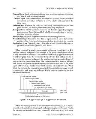
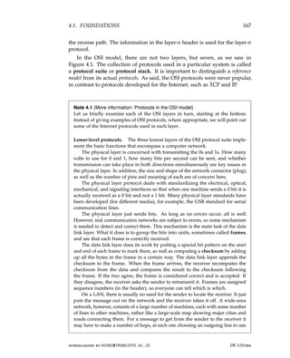
![168 CHAPTER 4. COMMUNICATION
The question of how to choose the best path is called routing, and is essentially
the primary task of the network layer.
The problem is complicated by the fact that the shortest route is not always
the best route. What really matters is the amount of delay on a given route, which,
in turn, is related to the amount of traffic and the number of messages queued up
for transmission over the various lines. The delay can thus change over the course
of time. Some routing algorithms try to adapt to changing loads, whereas others
are content to make decisions based on long-term averages.
At present, the most widely used network protocol is the connectionless IP
(Internet Protocol), which is part of the Internet protocol suite. An IP packet (the
technical term for a message in the network layer) can be sent without any setup.
Each IP packet is routed to its destination independent of all others. No internal
path is selected and remembered.
Transport protocols. The transport layer forms the last part of what could be
called a basic network protocol stack, in the sense that it implements all those
services that are not provided at the interface of the network layer, but which are
reasonably needed to build network applications. In other words, the transport
layer turns the underlying network into something that an application developer
can use.
Packets can be lost on the way from the sender to the receiver. Although
some applications can handle their own error recovery, others prefer a reliable
connection. The job of the transport layer is to provide this service. The idea is
that the application layer should be able to deliver a message to the transport
layer with the expectation that it will be delivered without loss.
Upon receiving a message from the application layer, the transport layer
breaks it into pieces small enough for transmission, assigns each one a sequence
number, and then sends them all. The discussion in the transport layer header
concerns which packets have been sent, which have been received, how many
more the receiver has room to accept, which should be retransmitted, and similar
topics.
Reliable transport connections (which by definition are connection-oriented)
can be built on top of connection-oriented or connectionless network services. In
the former case all the packets will arrive in the correct sequence (if they arrive at
all), but in the latter case it is possible for one packet to take a different route and
arrive earlier than the packet sent before it. It is up to the transport layer software
to put everything back in order to maintain the illusion that a transport connection
is like a big tube–you put messages into it and they come out undamaged and in
the same order in which they went in. Providing this end-to-end communication
behavior is an important aspect of the transport layer.
The Internet transport protocol is called TCP (Transmission Control Protocol)
and is described in detail by Comer [2013]. The combination TCP/IP is now used
as a de facto standard for network communication. The Internet protocol suite also
supports a connectionless transport protocol called UDP (Universal Datagram
DS 3.01pre downloaded by HUSNI@TRUNOJOYO.AC.ID
168 CHAPTER 4. COMMUNICATION
The question of how to choose the best path is called routing, and is essentially
the primary task of the network layer.
The problem is complicated by the fact that the shortest route is not always
the best route. What really matters is the amount of delay on a given route, which,
in turn, is related to the amount of traffic and the number of messages queued up
for transmission over the various lines. The delay can thus change over the course
of time. Some routing algorithms try to adapt to changing loads, whereas others
are content to make decisions based on long-term averages.
At present, the most widely used network protocol is the connectionless IP
(Internet Protocol), which is part of the Internet protocol suite. An IP packet (the
technical term for a message in the network layer) can be sent without any setup.
Each IP packet is routed to its destination independent of all others. No internal
path is selected and remembered.
Transport protocols. The transport layer forms the last part of what could be
called a basic network protocol stack, in the sense that it implements all those
services that are not provided at the interface of the network layer, but which are
reasonably needed to build network applications. In other words, the transport
layer turns the underlying network into something that an application developer
can use.
Packets can be lost on the way from the sender to the receiver. Although
some applications can handle their own error recovery, others prefer a reliable
connection. The job of the transport layer is to provide this service. The idea is
that the application layer should be able to deliver a message to the transport
layer with the expectation that it will be delivered without loss.
Upon receiving a message from the application layer, the transport layer
breaks it into pieces small enough for transmission, assigns each one a sequence
number, and then sends them all. The discussion in the transport layer header
concerns which packets have been sent, which have been received, how many
more the receiver has room to accept, which should be retransmitted, and similar
topics.
Reliable transport connections (which by definition are connection-oriented)
can be built on top of connection-oriented or connectionless network services. In
the former case all the packets will arrive in the correct sequence (if they arrive at
all), but in the latter case it is possible for one packet to take a different route and
arrive earlier than the packet sent before it. It is up to the transport layer software
to put everything back in order to maintain the illusion that a transport connection
is like a big tube–you put messages into it and they come out undamaged and in
the same order in which they went in. Providing this end-to-end communication
behavior is an important aspect of the transport layer.
The Internet transport protocol is called TCP (Transmission Control Protocol)
and is described in detail by Comer [2013]. The combination TCP/IP is now used
as a de facto standard for network communication. The Internet protocol suite also
supports a connectionless transport protocol called UDP (Universal Datagram
DS 3.01pre downloaded by HUSNI@TRUNOJOYO.AC.ID](https://image.slidesharecdn.com/distributed-systems-3rd-edition-251215232331-7e034da0/85/architectureec-distributed-systems-3rd-Edition-pdf-182-320.jpg)
![4.1. FOUNDATIONS 169
Protocol), which is essentially just IP with some minor additions. User programs
that do not need a connection-oriented protocol normally use UDP.
Additional transport protocols are regularly proposed. For example, to sup-
port real-time data transfer, the Real-time Transport Protocol (RTP) has been
defined. RTP is a framework protocol in the sense that it specifies packet formats
for real-time data without providing the actual mechanisms for guaranteeing
data delivery. In addition, it specifies a protocol for monitoring and controlling
data transfer of RTP packets [Schulzrinne et al., 2003]. Likewise, the Streaming
Control Transmission Protocol (SCTP) has been proposed as an alternative to
TCP [Stewart, 2007]. The main difference between SCTP and TCP is that SCTP
groups data into messages, whereas TCP merely moves bytes between processes.
Doing so may simplify application development.
Higher-level protocols. Above the transport layer, OSI distinguishes three addi-
tional layers. In practice, only the application layer is ever used. In fact, in the
Internet protocol suite, everything above the transport layer is grouped together.
In the face of middleware systems, we shall see that neither the OSI nor the
Internet approach is really appropriate.
The session layer is essentially an enhanced version of the transport layer. It
provides dialog control, to keep track of which party is currently talking, and it
provides synchronization facilities. The latter are useful to allow users to insert
checkpoints into long transfers, so that in the event of a crash, it is necessary to
go back only to the last checkpoint, rather than all the way back to the beginning.
In practice, few applications are interested in the session layer and it is rarely
supported. It is not even present in the Internet protocol suite. However, in
the context of developing middleware solutions, the concept of a session and
its related protocols has turned out to be quite relevant, notably when defining
higher-level communication protocols.
Unlike the lower layers, which are concerned with getting the bits from the
sender to the receiver reliably and efficiently, the presentation layer is concerned
with the meaning of the bits. Most messages do not consist of random bit strings,
but more structured information such as people’s names, addresses, amounts
of money, and so on. In the presentation layer it is possible to define records
containing fields like these and then have the sender notify the receiver that a
message contains a particular record in a certain format. This makes it easier for
machines with different internal representations to communicate with each other.
The OSI application layer was originally intended to contain a collection of
standard network applications such as those for electronic mail, file transfer, and
terminal emulation. By now, it has become the container for all applications and
protocols that in one way or the other do not fit into one of the underlying layers.
From the perspective of the OSI reference model, virtually all distributed systems
are just applications.
What is missing in this model is a clear distinction between applications,
application-specific protocols, and general-purpose protocols. For example, the
Internet File Transfer Protocol (FTP) [Postel and Reynolds, 1985; Horowitz and
downloaded by HUSNI@TRUNOJOYO.AC.ID DS 3.01pre
4.1. FOUNDATIONS 169
Protocol), which is essentially just IP with some minor additions. User programs
that do not need a connection-oriented protocol normally use UDP.
Additional transport protocols are regularly proposed. For example, to sup-
port real-time data transfer, the Real-time Transport Protocol (RTP) has been
defined. RTP is a framework protocol in the sense that it specifies packet formats
for real-time data without providing the actual mechanisms for guaranteeing
data delivery. In addition, it specifies a protocol for monitoring and controlling
data transfer of RTP packets [Schulzrinne et al., 2003]. Likewise, the Streaming
Control Transmission Protocol (SCTP) has been proposed as an alternative to
TCP [Stewart, 2007]. The main difference between SCTP and TCP is that SCTP
groups data into messages, whereas TCP merely moves bytes between processes.
Doing so may simplify application development.
Higher-level protocols. Above the transport layer, OSI distinguishes three addi-
tional layers. In practice, only the application layer is ever used. In fact, in the
Internet protocol suite, everything above the transport layer is grouped together.
In the face of middleware systems, we shall see that neither the OSI nor the
Internet approach is really appropriate.
The session layer is essentially an enhanced version of the transport layer. It
provides dialog control, to keep track of which party is currently talking, and it
provides synchronization facilities. The latter are useful to allow users to insert
checkpoints into long transfers, so that in the event of a crash, it is necessary to
go back only to the last checkpoint, rather than all the way back to the beginning.
In practice, few applications are interested in the session layer and it is rarely
supported. It is not even present in the Internet protocol suite. However, in
the context of developing middleware solutions, the concept of a session and
its related protocols has turned out to be quite relevant, notably when defining
higher-level communication protocols.
Unlike the lower layers, which are concerned with getting the bits from the
sender to the receiver reliably and efficiently, the presentation layer is concerned
with the meaning of the bits. Most messages do not consist of random bit strings,
but more structured information such as people’s names, addresses, amounts
of money, and so on. In the presentation layer it is possible to define records
containing fields like these and then have the sender notify the receiver that a
message contains a particular record in a certain format. This makes it easier for
machines with different internal representations to communicate with each other.
The OSI application layer was originally intended to contain a collection of
standard network applications such as those for electronic mail, file transfer, and
terminal emulation. By now, it has become the container for all applications and
protocols that in one way or the other do not fit into one of the underlying layers.
From the perspective of the OSI reference model, virtually all distributed systems
are just applications.
What is missing in this model is a clear distinction between applications,
application-specific protocols, and general-purpose protocols. For example, the
Internet File Transfer Protocol (FTP) [Postel and Reynolds, 1985; Horowitz and
downloaded by HUSNI@TRUNOJOYO.AC.ID DS 3.01pre](https://image.slidesharecdn.com/distributed-systems-3rd-edition-251215232331-7e034da0/85/architectureec-distributed-systems-3rd-Edition-pdf-183-320.jpg)
![170 CHAPTER 4. COMMUNICATION
Lunt, 1997] defines a protocol for transferring files between a client and server
machine. The protocol should not be confused with the ftp program, which
is an end-user application for transferring files and which also (not entirely by
coincidence) happens to implement the Internet FTP.
Another example of a typical application-specific protocol is the HyperText
Transfer Protocol (HTTP) [Fielding et al., 1999] which is designed to remotely
manage and handle the transfer of Web pages. The protocol is implemented by
applications such as Web browsers and Web servers. However, HTTP is now also
used by systems that are not intrinsically tied to the Web. For example, Java’s
object-invocation mechanism can use HTTP to request the invocation of remote
objects that are protected by a firewall [Oracle, 2010].
There are also many general-purpose protocols that are useful to many appli-
cations, but which cannot be qualified as transport protocols. In many cases, such
protocols fall into the category of middleware protocols.
Middleware protocols
Middleware is an application that logically lives (mostly) in the OSI application
layer, but which contains many general-purpose protocols that warrant their
own layers, independent of other, more specific applications. Let us briefly
look at some examples.
The Domain Name System (DNS) [Liu and Albitz, 2006] is a distributed
service that is used to look up a network address associated with a name, such
as the address of a so-called domain name like www.distributed-systems.net.
In terms of the OSI reference model, DNS is an application and therefore
is logically placed in the application layer. However, it should be quite
obvious that DNS is offering a general-purpose, application-independent
service. Arguably, it forms part of the middleware.
As another example, there are various ways to establish authentication,
that is, provide proof of a claimed identity. Authentication protocols are
not closely tied to any specific application, but instead, can be integrated
into a middleware system as a general service. Likewise, authorization
protocols by which authenticated users and processes are granted access only
to those resources for which they have authorization, tend to have a general,
application-independent nature. Being labeled as applications in the OSI
reference model, these are clear examples that belong in the middleware.
Distributed commit protocols establish that in a group of processes, possi-
bly spread out across a number of machines, either all processes carry out a
particular operation, or that the operation is not carried out at all. This phe-
nomenon is also referred to as atomicity and is widely applied in transactions.
As it turns out, commit protocols can present an interface independently of
specific applications, thus providing a general-purpose transaction service.
DS 3.01pre downloaded by HUSNI@TRUNOJOYO.AC.ID
170 CHAPTER 4. COMMUNICATION
Lunt, 1997] defines a protocol for transferring files between a client and server
machine. The protocol should not be confused with the ftp program, which
is an end-user application for transferring files and which also (not entirely by
coincidence) happens to implement the Internet FTP.
Another example of a typical application-specific protocol is the HyperText
Transfer Protocol (HTTP) [Fielding et al., 1999] which is designed to remotely
manage and handle the transfer of Web pages. The protocol is implemented by
applications such as Web browsers and Web servers. However, HTTP is now also
used by systems that are not intrinsically tied to the Web. For example, Java’s
object-invocation mechanism can use HTTP to request the invocation of remote
objects that are protected by a firewall [Oracle, 2010].
There are also many general-purpose protocols that are useful to many appli-
cations, but which cannot be qualified as transport protocols. In many cases, such
protocols fall into the category of middleware protocols.
Middleware protocols
Middleware is an application that logically lives (mostly) in the OSI application
layer, but which contains many general-purpose protocols that warrant their
own layers, independent of other, more specific applications. Let us briefly
look at some examples.
The Domain Name System (DNS) [Liu and Albitz, 2006] is a distributed
service that is used to look up a network address associated with a name, such
as the address of a so-called domain name like www.distributed-systems.net.
In terms of the OSI reference model, DNS is an application and therefore
is logically placed in the application layer. However, it should be quite
obvious that DNS is offering a general-purpose, application-independent
service. Arguably, it forms part of the middleware.
As another example, there are various ways to establish authentication,
that is, provide proof of a claimed identity. Authentication protocols are
not closely tied to any specific application, but instead, can be integrated
into a middleware system as a general service. Likewise, authorization
protocols by which authenticated users and processes are granted access only
to those resources for which they have authorization, tend to have a general,
application-independent nature. Being labeled as applications in the OSI
reference model, these are clear examples that belong in the middleware.
Distributed commit protocols establish that in a group of processes, possi-
bly spread out across a number of machines, either all processes carry out a
particular operation, or that the operation is not carried out at all. This phe-
nomenon is also referred to as atomicity and is widely applied in transactions.
As it turns out, commit protocols can present an interface independently of
specific applications, thus providing a general-purpose transaction service.
DS 3.01pre downloaded by HUSNI@TRUNOJOYO.AC.ID](https://image.slidesharecdn.com/distributed-systems-3rd-edition-251215232331-7e034da0/85/architectureec-distributed-systems-3rd-Edition-pdf-184-320.jpg)
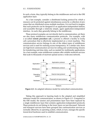
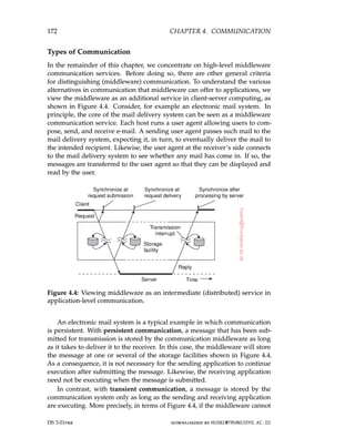
![4.2. REMOTE PROCEDURE CALL 173
deliver a message due to a transmission interrupt, or because the recipient is
currently not active, it will simply be discarded. Typically, all transport-level
communication services offer only transient communication. In this case, the
communication system consists of traditional store-and-forward routers. If a
router cannot deliver a message to the next one or the destination host, it will
simply drop the message.
Besides being persistent or transient, communication can also be asyn-
chronous or synchronous. The characteristic feature of asynchronous com-
munication is that a sender continues immediately after it has submitted its
message for transmission. This means that the message is (temporarily) stored
immediately by the middleware upon submission. With synchronous com-
munication, the sender is blocked until its request is known to be accepted.
There are essentially three points where synchronization can take place. First,
the sender may be blocked until the middleware notifies that it will take over
transmission of the request. Second, the sender may synchronize until its
request has been delivered to the intended recipient. Third, synchronization
may take place by letting the sender wait until its request has been fully
processed, that is, up to the time that the recipient returns a response.
Various combinations of persistence and synchronization occur in practice.
Popular ones are persistence in combination with synchronization at request
submission, which is a common scheme for many message-queuing systems,
which we discuss later in this chapter. Likewise, transient communication
with synchronization after the request has been fully processed is also widely
used. This scheme corresponds with remote procedure calls, which we discuss
next.
4.2 Remote procedure call
Many distributed systems have been based on explicit message exchange
between processes. However, the operations send and receive do not conceal
communication at all, which is important to achieve access transparency in
distributed systems. This problem has long been known, but little was done
about it until researchers in the 1980s [Birrell and Nelson, 1984] introduced
a completely different way of handling communication. Although the idea
is refreshingly simple (once someone has thought of it), the implications are
often subtle. In this section we will examine the concept, its implementation,
its strengths, and its weaknesses.
In a nutshell, the proposal was to allow programs to call procedures
located on other machines. When a process on machine A calls a procedure on
machine B, the calling process on A is suspended, and execution of the called
procedure takes place on B. Information can be transported from the caller to
the callee in the parameters and can come back in the procedure result. No
message passing at all is visible to the programmer. This method is known as
downloaded by HUSNI@TRUNOJOYO.AC.ID DS 3.01pre
4.2. REMOTE PROCEDURE CALL 173
deliver a message due to a transmission interrupt, or because the recipient is
currently not active, it will simply be discarded. Typically, all transport-level
communication services offer only transient communication. In this case, the
communication system consists of traditional store-and-forward routers. If a
router cannot deliver a message to the next one or the destination host, it will
simply drop the message.
Besides being persistent or transient, communication can also be asyn-
chronous or synchronous. The characteristic feature of asynchronous com-
munication is that a sender continues immediately after it has submitted its
message for transmission. This means that the message is (temporarily) stored
immediately by the middleware upon submission. With synchronous com-
munication, the sender is blocked until its request is known to be accepted.
There are essentially three points where synchronization can take place. First,
the sender may be blocked until the middleware notifies that it will take over
transmission of the request. Second, the sender may synchronize until its
request has been delivered to the intended recipient. Third, synchronization
may take place by letting the sender wait until its request has been fully
processed, that is, up to the time that the recipient returns a response.
Various combinations of persistence and synchronization occur in practice.
Popular ones are persistence in combination with synchronization at request
submission, which is a common scheme for many message-queuing systems,
which we discuss later in this chapter. Likewise, transient communication
with synchronization after the request has been fully processed is also widely
used. This scheme corresponds with remote procedure calls, which we discuss
next.
4.2 Remote procedure call
Many distributed systems have been based on explicit message exchange
between processes. However, the operations send and receive do not conceal
communication at all, which is important to achieve access transparency in
distributed systems. This problem has long been known, but little was done
about it until researchers in the 1980s [Birrell and Nelson, 1984] introduced
a completely different way of handling communication. Although the idea
is refreshingly simple (once someone has thought of it), the implications are
often subtle. In this section we will examine the concept, its implementation,
its strengths, and its weaknesses.
In a nutshell, the proposal was to allow programs to call procedures
located on other machines. When a process on machine A calls a procedure on
machine B, the calling process on A is suspended, and execution of the called
procedure takes place on B. Information can be transported from the caller to
the callee in the parameters and can come back in the procedure result. No
message passing at all is visible to the programmer. This method is known as
downloaded by HUSNI@TRUNOJOYO.AC.ID DS 3.01pre](https://image.slidesharecdn.com/distributed-systems-3rd-edition-251215232331-7e034da0/85/architectureec-distributed-systems-3rd-Edition-pdf-187-320.jpg)
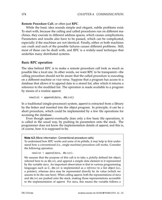
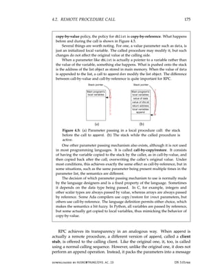
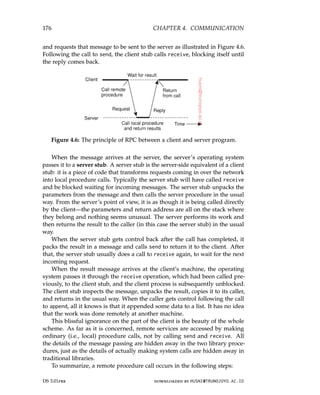
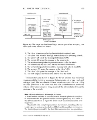
![178 CHAPTER 4. COMMUNICATION
of append. When called with parameters data and dbList, the following happens.
The call is transformed into a tuple (APPEND, data, dbList) containing all the
information the server would need to do its work. The client stub then sends
the request off to the server, and subsequently waits for the response. When the
response comes in, it finishes by passing the result to the program that initially
called the stub.
1 import channel, pickle
2
3 class DBList:
4 def append(self, data):
5 self.value = self.value + [data]
6 return self
7
8 class Client:
9 def append(self, data, dbList):
10 msglst = (APPEND, data, dbList) # message payload
11 self.chan.sendTo(self.server, msglst) # send msg to server
12 msgrcv = self.chan.recvFrom(self.server) # wait for response
13 return msgrcv[1] # pass it to caller
14
15 class Server:
16 def append(self, data, dbList):
17 return dbList.append(data)
18
19 def run(self):
20 while True:
21 msgreq = self.chan.recvFromAny() # wait for any request
22 client = msgreq[0] # see who is the caller
23 msgrpc = msgreq[1] # fetch call parameters
24 if APPEND == msgrpc[0]: # check what is being requested
25 result = self.append(msgrpc[1], msgrpc[2]) # do local call
26 self.chan.sendTo([client],result) # return response
Figure 4.8: A simple RPC example for operation append.
On the server side, we see that in the server stub, the server waits for any
incoming message, and inspects which operation it is required to call. Assuming
it received a request to call append, it then simply does a local call to its imple-
mentation of append with the appropriate parameters as also found in the request
tuple. The result is then sent off to the client.
Parameter passing
The function of the client stub is to take its parameters, pack them into a
message, and send them to the server stub. While this sounds straightforward,
it is not quite as simple as it at first appears.
Packing parameters into a message is called parameter marshaling. Re-
turning to our append operation, we thus need to ensure that its two parame-
DS 3.01pre downloaded by HUSNI@TRUNOJOYO.AC.ID
178 CHAPTER 4. COMMUNICATION
of append. When called with parameters data and dbList, the following happens.
The call is transformed into a tuple (APPEND, data, dbList) containing all the
information the server would need to do its work. The client stub then sends
the request off to the server, and subsequently waits for the response. When the
response comes in, it finishes by passing the result to the program that initially
called the stub.
1 import channel, pickle
2
3 class DBList:
4 def append(self, data):
5 self.value = self.value + [data]
6 return self
7
8 class Client:
9 def append(self, data, dbList):
10 msglst = (APPEND, data, dbList) # message payload
11 self.chan.sendTo(self.server, msglst) # send msg to server
12 msgrcv = self.chan.recvFrom(self.server) # wait for response
13 return msgrcv[1] # pass it to caller
14
15 class Server:
16 def append(self, data, dbList):
17 return dbList.append(data)
18
19 def run(self):
20 while True:
21 msgreq = self.chan.recvFromAny() # wait for any request
22 client = msgreq[0] # see who is the caller
23 msgrpc = msgreq[1] # fetch call parameters
24 if APPEND == msgrpc[0]: # check what is being requested
25 result = self.append(msgrpc[1], msgrpc[2]) # do local call
26 self.chan.sendTo([client],result) # return response
Figure 4.8: A simple RPC example for operation append.
On the server side, we see that in the server stub, the server waits for any
incoming message, and inspects which operation it is required to call. Assuming
it received a request to call append, it then simply does a local call to its imple-
mentation of append with the appropriate parameters as also found in the request
tuple. The result is then sent off to the client.
Parameter passing
The function of the client stub is to take its parameters, pack them into a
message, and send them to the server stub. While this sounds straightforward,
it is not quite as simple as it at first appears.
Packing parameters into a message is called parameter marshaling. Re-
turning to our append operation, we thus need to ensure that its two parame-
DS 3.01pre downloaded by HUSNI@TRUNOJOYO.AC.ID](https://image.slidesharecdn.com/distributed-systems-3rd-edition-251215232331-7e034da0/85/architectureec-distributed-systems-3rd-Edition-pdf-192-320.jpg)
![180 CHAPTER 4. COMMUNICATION
In this example, we use the Python pickle library for marshaling and unmar-
shaling data structures. Note that the code hardly changes in comparison to what
we have shown in Figure 4.8. The only changes occur just before sending, and
after receiving a message. Also note that both client and server are programmed
to work on the same data structures, as we discussed above.
1 import channel, pickle
2
3 class Client:
4 def append(self, data, dbList):
5 msglst = (APPEND, data, dbList) # message payload
6 msgsnd = pickle.dumps(msglst) # wrap call
7 self.chan.sendTo(self.server, msgsnd) # send request to server
8 msgrcv = self.chan.recvFrom(self.server) # wait for response
9 retval = pickle.loads(msgrcv[1]) # unwrap return value
10 return retval # pass it to caller
11
12 class Server:
13 def run(self):
14 while True:
15 msgreq = self.chan.recvFromAny() # wait for any request
16 client = msgreq[0] # see who is the caller
17 msgrpc = pickle.loads(msgreq[1]) # unwrap the call
18 if APPEND == msgrpc[0]: # check what is being requested
19 result = self.append(msgrpc[1], msgrpc[2]) # do local call
20 msgres = pickle.dumps(result) # wrap the result
21 self.chan.sendTo([client],msgres) # send response
Figure 4.9: A simple RPC example for operation append, but now with
proper marshaling.
One solution is just to forbid pointers and reference parameters in general.
However, these are so important that this solution is highly undesirable. In
fact, it is often not necessary either. First, reference parameters are often used
with fixed-sized data types, such as static arrays, or with dynamic data types
for which it is easy to compute their size at runtime, such as strings or dynamic
arrays. In such cases, we can simply copy the entire data structure to which the
parameter is referring, effectively replacing the copy-by-reference mechanism
by copy-by-value/restore. Although this is semantically not always identical,
it frequently is good enough. An obvious optimization is that when the client
stub knows the referred data will be only read, there is no need to copy it
back when the call has finished. Copy-by-value is thus good enough.
More intricate data types can often be supported as well, and certainly if a
programming language supports those data types. For example, a language
such as Python or Java supports user-defined classes, allowing a language
system to provide fully automated marshaling and unmarshaling of those data
types. Note, however, that as soon as we are dealing with very large, nested,
DS 3.01pre downloaded by HUSNI@TRUNOJOYO.AC.ID
180 CHAPTER 4. COMMUNICATION
In this example, we use the Python pickle library for marshaling and unmar-
shaling data structures. Note that the code hardly changes in comparison to what
we have shown in Figure 4.8. The only changes occur just before sending, and
after receiving a message. Also note that both client and server are programmed
to work on the same data structures, as we discussed above.
1 import channel, pickle
2
3 class Client:
4 def append(self, data, dbList):
5 msglst = (APPEND, data, dbList) # message payload
6 msgsnd = pickle.dumps(msglst) # wrap call
7 self.chan.sendTo(self.server, msgsnd) # send request to server
8 msgrcv = self.chan.recvFrom(self.server) # wait for response
9 retval = pickle.loads(msgrcv[1]) # unwrap return value
10 return retval # pass it to caller
11
12 class Server:
13 def run(self):
14 while True:
15 msgreq = self.chan.recvFromAny() # wait for any request
16 client = msgreq[0] # see who is the caller
17 msgrpc = pickle.loads(msgreq[1]) # unwrap the call
18 if APPEND == msgrpc[0]: # check what is being requested
19 result = self.append(msgrpc[1], msgrpc[2]) # do local call
20 msgres = pickle.dumps(result) # wrap the result
21 self.chan.sendTo([client],msgres) # send response
Figure 4.9: A simple RPC example for operation append, but now with
proper marshaling.
One solution is just to forbid pointers and reference parameters in general.
However, these are so important that this solution is highly undesirable. In
fact, it is often not necessary either. First, reference parameters are often used
with fixed-sized data types, such as static arrays, or with dynamic data types
for which it is easy to compute their size at runtime, such as strings or dynamic
arrays. In such cases, we can simply copy the entire data structure to which the
parameter is referring, effectively replacing the copy-by-reference mechanism
by copy-by-value/restore. Although this is semantically not always identical,
it frequently is good enough. An obvious optimization is that when the client
stub knows the referred data will be only read, there is no need to copy it
back when the call has finished. Copy-by-value is thus good enough.
More intricate data types can often be supported as well, and certainly if a
programming language supports those data types. For example, a language
such as Python or Java supports user-defined classes, allowing a language
system to provide fully automated marshaling and unmarshaling of those data
types. Note, however, that as soon as we are dealing with very large, nested,
DS 3.01pre downloaded by HUSNI@TRUNOJOYO.AC.ID](https://image.slidesharecdn.com/distributed-systems-3rd-edition-251215232331-7e034da0/85/architectureec-distributed-systems-3rd-Edition-pdf-194-320.jpg)
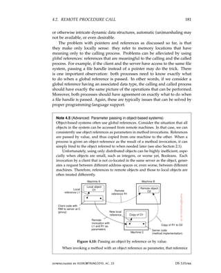
![182 CHAPTER 4. COMMUNICATION
is copied and passed as a value parameter only when it refers to a remote object.
In this case, the object is literally passed by reference. However, when the reference
refers to a local object, that is an object in the same address space as the client,
the referred object is copied as a whole and passed along with the invocation. In
other words, the object is passed by value.
These two situations are illustrated in Figure 4.10 which shows a client pro-
gram running on machine A, and a server program on machine C. The client has
a reference to a local object O1 that it uses as a parameter when calling the server
program on machine C. In addition, it holds a reference to a remote object O2
residing at machine B, which is also used as a parameter. When calling the server,
a copy of O1 is passed to the server on machine C, along with only a copy of the
reference to O2.
Note that whether we are dealing with a reference to a local object or a
reference to a remote object can be highly transparent, such as in Java. In Java, the
distinction is visible only because local objects are essentially of a different data
type than remote objects. Otherwise, both types of references are treated very
much the same (see also [Wollrath et al., 1996]). On the other hand, when using
conventional programming languages such as C, a reference to a local object can
be as simple as a pointer, which can never be used to refer to a remote object.
The side effect of invoking a method with an object reference as parameter is
that we may be copying an object. Obviously, hiding this aspect is unacceptable,
so that we are consequently forced to make an explicit distinction between local
and distributed objects. Clearly, this distinction not only violates distribution
transparency, but also makes it harder to write distributed applications.
We can now also easily explain how global references can be implemented
when using portable, interpreted languages such as Python or Java: use the entire
client stub as a reference. The key observation is that a client stub is often just
another data structure that is compiled into (portable) bytecode. That compiled
code can actually be transferred across the network and executed at the receiver’s
side. In other words, there is no need for explicit binding anymore; simply
copying the client stub to the recipient is enough to allow the latter to invoke the
associated server-side object.
RPC-based application support
From what we have explained so far, it is clear that hiding a remote procedure
call requires that the caller and the callee agree on the format of the messages
they exchange and that they follow the same steps when it comes to, for
example, passing complex data structures. In other words, both sides in an
RPC should follow the same protocol or the RPC will not work correctly.
There are at least two ways in which RPC-based application development can
be supported. The first one is to let a developer specify exactly what needs
to be called remotely, from which complete client-side and server-side stubs
can be generated. A second approach is to embed remote procedure calling
as part of a programming-language environment.
DS 3.01pre downloaded by HUSNI@TRUNOJOYO.AC.ID
182 CHAPTER 4. COMMUNICATION
is copied and passed as a value parameter only when it refers to a remote object.
In this case, the object is literally passed by reference. However, when the reference
refers to a local object, that is an object in the same address space as the client,
the referred object is copied as a whole and passed along with the invocation. In
other words, the object is passed by value.
These two situations are illustrated in Figure 4.10 which shows a client pro-
gram running on machine A, and a server program on machine C. The client has
a reference to a local object O1 that it uses as a parameter when calling the server
program on machine C. In addition, it holds a reference to a remote object O2
residing at machine B, which is also used as a parameter. When calling the server,
a copy of O1 is passed to the server on machine C, along with only a copy of the
reference to O2.
Note that whether we are dealing with a reference to a local object or a
reference to a remote object can be highly transparent, such as in Java. In Java, the
distinction is visible only because local objects are essentially of a different data
type than remote objects. Otherwise, both types of references are treated very
much the same (see also [Wollrath et al., 1996]). On the other hand, when using
conventional programming languages such as C, a reference to a local object can
be as simple as a pointer, which can never be used to refer to a remote object.
The side effect of invoking a method with an object reference as parameter is
that we may be copying an object. Obviously, hiding this aspect is unacceptable,
so that we are consequently forced to make an explicit distinction between local
and distributed objects. Clearly, this distinction not only violates distribution
transparency, but also makes it harder to write distributed applications.
We can now also easily explain how global references can be implemented
when using portable, interpreted languages such as Python or Java: use the entire
client stub as a reference. The key observation is that a client stub is often just
another data structure that is compiled into (portable) bytecode. That compiled
code can actually be transferred across the network and executed at the receiver’s
side. In other words, there is no need for explicit binding anymore; simply
copying the client stub to the recipient is enough to allow the latter to invoke the
associated server-side object.
RPC-based application support
From what we have explained so far, it is clear that hiding a remote procedure
call requires that the caller and the callee agree on the format of the messages
they exchange and that they follow the same steps when it comes to, for
example, passing complex data structures. In other words, both sides in an
RPC should follow the same protocol or the RPC will not work correctly.
There are at least two ways in which RPC-based application development can
be supported. The first one is to let a developer specify exactly what needs
to be called remotely, from which complete client-side and server-side stubs
can be generated. A second approach is to embed remote procedure calling
as part of a programming-language environment.
DS 3.01pre downloaded by HUSNI@TRUNOJOYO.AC.ID](https://image.slidesharecdn.com/distributed-systems-3rd-edition-251215232331-7e034da0/85/architectureec-distributed-systems-3rd-Edition-pdf-196-320.jpg)
![4.2. REMOTE PROCEDURE CALL 183
Stub generation
Consider the function someFunction of Figure 4.11(a). It has three parameters,
a character, a floating-point number, and an array of five integers. Assuming a
word is four bytes, the RPC protocol might prescribe that we should transmit a
character in the rightmost byte of a word (leaving the next three bytes empty),
a float as a whole word, and an array as a group of words equal to the array
length, preceded by a word giving the length, as shown in Figure 4.11(b).
Thus given these rules, the client stub for someFunction knows that it must
use the format of Figure 4.11(b), and the server stub knows that incoming
messages for someFunction will have the format of Figure 4.11(b).
void someFunction(char x; float y; int z[5])
(a)
(b)
Figure 4.11: (a) A function. (b) The corresponding message, and the order in
which bytes and words are sent across the network.
Defining the message format is one aspect of an RPC protocol, but it
is not sufficient. What we also need is the client and the server to agree
on the representation of simple data structures, such as integers, characters,
Booleans, etc. For example, the protocol could prescribe that integers are
represented in two’s complement, characters in 16-bit Unicode, and floats in
the IEEE standard #754 format, with everything stored in little endian. With
this additional information, messages can be unambiguously interpreted.
With the encoding rules now pinned down to the last bit, the only thing
that remains to be done is that the caller and callee agree on the actual
exchange of messages. For example, it may be decided to use a connection-
oriented transport service such as TCP/IP. An alternative is to use an unreli-
able datagram service and let the client and server implement an error control
scheme as part of the RPC protocol. In practice, several variants exist, and it
is up to the developer to indicate the preferred underlying communication
service.
Once the RPC protocol has been fully defined, the client and server stubs
downloaded by HUSNI@TRUNOJOYO.AC.ID DS 3.01pre
4.2. REMOTE PROCEDURE CALL 183
Stub generation
Consider the function someFunction of Figure 4.11(a). It has three parameters,
a character, a floating-point number, and an array of five integers. Assuming a
word is four bytes, the RPC protocol might prescribe that we should transmit a
character in the rightmost byte of a word (leaving the next three bytes empty),
a float as a whole word, and an array as a group of words equal to the array
length, preceded by a word giving the length, as shown in Figure 4.11(b).
Thus given these rules, the client stub for someFunction knows that it must
use the format of Figure 4.11(b), and the server stub knows that incoming
messages for someFunction will have the format of Figure 4.11(b).
void someFunction(char x; float y; int z[5])
(a)
(b)
Figure 4.11: (a) A function. (b) The corresponding message, and the order in
which bytes and words are sent across the network.
Defining the message format is one aspect of an RPC protocol, but it
is not sufficient. What we also need is the client and the server to agree
on the representation of simple data structures, such as integers, characters,
Booleans, etc. For example, the protocol could prescribe that integers are
represented in two’s complement, characters in 16-bit Unicode, and floats in
the IEEE standard #754 format, with everything stored in little endian. With
this additional information, messages can be unambiguously interpreted.
With the encoding rules now pinned down to the last bit, the only thing
that remains to be done is that the caller and callee agree on the actual
exchange of messages. For example, it may be decided to use a connection-
oriented transport service such as TCP/IP. An alternative is to use an unreli-
able datagram service and let the client and server implement an error control
scheme as part of the RPC protocol. In practice, several variants exist, and it
is up to the developer to indicate the preferred underlying communication
service.
Once the RPC protocol has been fully defined, the client and server stubs
downloaded by HUSNI@TRUNOJOYO.AC.ID DS 3.01pre](https://image.slidesharecdn.com/distributed-systems-3rd-edition-251215232331-7e034da0/85/architectureec-distributed-systems-3rd-Edition-pdf-197-320.jpg)
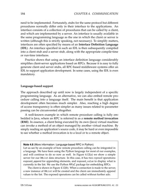
![4.2. REMOTE PROCEDURE CALL 185
1 import rpyc
2 from rpyc.utils.server import ForkingServer
3
4 class DBList(rpyc.Service):
5 value = []
6
7 def exposed_append(self, data):
8 self.value = self.value + [data]
9 return self.value
10
11 def exposed_value(self):
12 return self.value
13
14 if __name__ == __main__:
15 server = ForkingServer(DBList, port = 12345)
16 server.start()
Figure 4.12: (a) Embedding RPCs in a language: a server.
1 import rpyc
2
3 class Client:
4 conn = rpyc.connect(SERVER, PORT) # Connect to the server
5 conn.root.exposed_append(2) # Call an exposed operation,
6 conn.root.exposed_append(4) # and append two elements
7 print conn.root.exposed_value() # Print the result
Figure 4.12: (b) Embedding RPCs in a language: a client.
This example also illustrates a subtle issue: apparently the instance of DBList
created for the client is new, and unique. In other words, as soon as the client
breaks the connection to the server, the list will be lost. It is a transient object so
to say, and special measures will need to be taken to make it a persistent object.
Variations on RPC
As in conventional procedure calls, when a client calls a remote procedure, the
client will block until a reply is returned. This strict request-reply behavior
is unnecessary when there is no result to return, or may hinder efficiency
when multiple RPCs need to be performed. In the following we look at two
variations on the RPC scheme we have discussed so far.
Asynchronous RPC
To support situations in which there is simply no result to return to the client,
RPC systems may provide facilities for what are called asynchronous RPCs.
With asynchronous RPCs, the server, in principle, immediately sends a reply
downloaded by HUSNI@TRUNOJOYO.AC.ID DS 3.01pre
4.2. REMOTE PROCEDURE CALL 185
1 import rpyc
2 from rpyc.utils.server import ForkingServer
3
4 class DBList(rpyc.Service):
5 value = []
6
7 def exposed_append(self, data):
8 self.value = self.value + [data]
9 return self.value
10
11 def exposed_value(self):
12 return self.value
13
14 if __name__ == __main__:
15 server = ForkingServer(DBList, port = 12345)
16 server.start()
Figure 4.12: (a) Embedding RPCs in a language: a server.
1 import rpyc
2
3 class Client:
4 conn = rpyc.connect(SERVER, PORT) # Connect to the server
5 conn.root.exposed_append(2) # Call an exposed operation,
6 conn.root.exposed_append(4) # and append two elements
7 print conn.root.exposed_value() # Print the result
Figure 4.12: (b) Embedding RPCs in a language: a client.
This example also illustrates a subtle issue: apparently the instance of DBList
created for the client is new, and unique. In other words, as soon as the client
breaks the connection to the server, the list will be lost. It is a transient object so
to say, and special measures will need to be taken to make it a persistent object.
Variations on RPC
As in conventional procedure calls, when a client calls a remote procedure, the
client will block until a reply is returned. This strict request-reply behavior
is unnecessary when there is no result to return, or may hinder efficiency
when multiple RPCs need to be performed. In the following we look at two
variations on the RPC scheme we have discussed so far.
Asynchronous RPC
To support situations in which there is simply no result to return to the client,
RPC systems may provide facilities for what are called asynchronous RPCs.
With asynchronous RPCs, the server, in principle, immediately sends a reply
downloaded by HUSNI@TRUNOJOYO.AC.ID DS 3.01pre](https://image.slidesharecdn.com/distributed-systems-3rd-edition-251215232331-7e034da0/85/architectureec-distributed-systems-3rd-Edition-pdf-199-320.jpg)
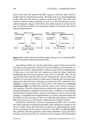
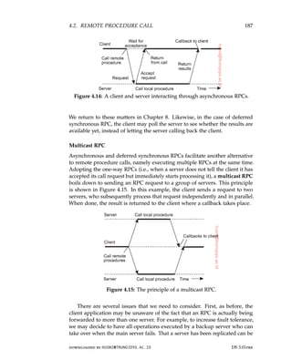
![188 CHAPTER 4. COMMUNICATION
completely hidden from a client application by an appropriate stub. Yet even
the stub need not be aware that the server is replicated, for example, because
we are using a transport-level multicast address.
Second, we need to consider what to do with the responses. In particular,
will the client proceed after all responses have been received, or wait just for
one? It all depends. When the server has been replicated for fault tolerance,
we may decide to wait for just the first response, or perhaps until a majority
of the servers returns the same result. On the other hand, if the servers have
been replicated to do the same work but on different parts of the input, their
results may need to be merged before the client can continue. Again, such
matters can be hidden in the client-side stub, yet the application developer
will, at the very least, have to specify the purpose of the multicast RPC.
Example: DCE RPC
Remote procedure calls have been widely adopted as the basis of middleware
and distributed systems in general. In this section, we take a closer look at the
Distributed Computing Environment (DCE) which was developed by the
Open Software Foundation (OSF), now called The Open Group. It forms the
basis for Microsoft’s distributed computing environment DCOM [Eddon and
Eddon, 1998] and used in Samba, a file server and accompanying protocol suite
allowing the Windows file system to be accessed through remote procedure
calls from non-Windows systems.
Although DCE RPC is arguably not the most modern way of managing
RPCs, it is worthwhile discussing some of its details, notably because it
is representative for most traditional RPC systems that use a combination
of interface specifications and explicit bindings to various programming
languages. We start with a brief introduction to DCE, after which we consider
its principal workings. Details on how to develop RPC-based applications can
be found in [Stevens, 1999].
Introduction to DCE
DCE is a true middleware system in that it is designed to execute as a layer
of abstraction between existing (network) operating systems and distributed
applications. Initially designed for Unix, it has now been ported to all major
operating systems. The idea is that the customer can take a collection of
existing machines, add the DCE software, and then be able to run distributed
applications, all without disturbing existing (nondistributed) applications.
Although most of the DCE package runs in user space, in some configurations
a piece (part of the distributed file system) must be added to the kernel of the
underlying operating system.
The programming model underlying DCE is the client-server model. User
processes act as clients to access remote services provided by server processes.
DS 3.01pre downloaded by HUSNI@TRUNOJOYO.AC.ID
188 CHAPTER 4. COMMUNICATION
completely hidden from a client application by an appropriate stub. Yet even
the stub need not be aware that the server is replicated, for example, because
we are using a transport-level multicast address.
Second, we need to consider what to do with the responses. In particular,
will the client proceed after all responses have been received, or wait just for
one? It all depends. When the server has been replicated for fault tolerance,
we may decide to wait for just the first response, or perhaps until a majority
of the servers returns the same result. On the other hand, if the servers have
been replicated to do the same work but on different parts of the input, their
results may need to be merged before the client can continue. Again, such
matters can be hidden in the client-side stub, yet the application developer
will, at the very least, have to specify the purpose of the multicast RPC.
Example: DCE RPC
Remote procedure calls have been widely adopted as the basis of middleware
and distributed systems in general. In this section, we take a closer look at the
Distributed Computing Environment (DCE) which was developed by the
Open Software Foundation (OSF), now called The Open Group. It forms the
basis for Microsoft’s distributed computing environment DCOM [Eddon and
Eddon, 1998] and used in Samba, a file server and accompanying protocol suite
allowing the Windows file system to be accessed through remote procedure
calls from non-Windows systems.
Although DCE RPC is arguably not the most modern way of managing
RPCs, it is worthwhile discussing some of its details, notably because it
is representative for most traditional RPC systems that use a combination
of interface specifications and explicit bindings to various programming
languages. We start with a brief introduction to DCE, after which we consider
its principal workings. Details on how to develop RPC-based applications can
be found in [Stevens, 1999].
Introduction to DCE
DCE is a true middleware system in that it is designed to execute as a layer
of abstraction between existing (network) operating systems and distributed
applications. Initially designed for Unix, it has now been ported to all major
operating systems. The idea is that the customer can take a collection of
existing machines, add the DCE software, and then be able to run distributed
applications, all without disturbing existing (nondistributed) applications.
Although most of the DCE package runs in user space, in some configurations
a piece (part of the distributed file system) must be added to the kernel of the
underlying operating system.
The programming model underlying DCE is the client-server model. User
processes act as clients to access remote services provided by server processes.
DS 3.01pre downloaded by HUSNI@TRUNOJOYO.AC.ID](https://image.slidesharecdn.com/distributed-systems-3rd-edition-251215232331-7e034da0/85/architectureec-distributed-systems-3rd-Edition-pdf-202-320.jpg)
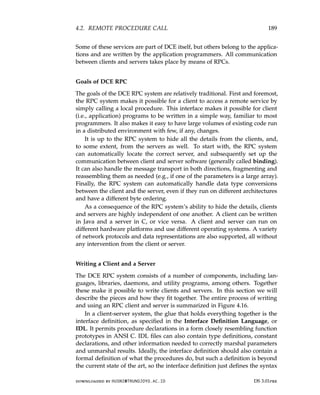
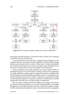
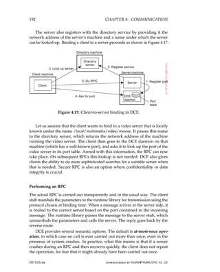
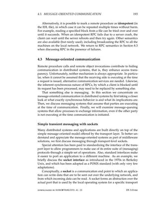
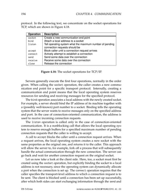
![4.3. MESSAGE-ORIENTED COMMUNICATION 195
Figure 4.19: Connection-oriented communication pattern using sockets.
receive operations. Finally, closing a connection is symmetric when using
sockets, and is established by having both the client and server call the close
operation. Although there are many exceptions to the rule, the general pattern
followed by a client and server for connection-oriented communication using
sockets is as shown in Figure 4.19. Details on network programming using
sockets and other interfaces in Unix can be found in [Stevens, 1998].
Note 4.7 (Example: A simple socket-based client-server system)
As an illustration of the recurring pattern in Figure 4.19, consider the simple
socket-based client-server system shown below (see also Note 2.1). We see the
server [Figure 4.20(a)] starting by creating a socket, and subsequently binding an
address to that socket. It calls the listen operation, and waits for an incoming
connection request. When the server accepts a connection, the socket library
creates a separate connection, conn, which is used to receive data and send a
response to the connected client. The server enters a loop receiving and sending
messages, until no more data has been received. It then closes the connection.
1 from socket import *
2 s = socket(AF_INET, SOCK_STREAM)
3 s.bind((HOST, PORT))
4 s.listen(1)
5 (conn, addr) = s.accept() # returns new socket and addr. client
6 while True: # forever
7 data = conn.recv(1024) # receive data from client
8 if not data: break # stop if client stopped
9 conn.send(str(data)+*) # return sent data plus an *
10 conn.close() # close the connection
Figure 4.20: (a) A simple socket-based client-server system: the server.
The client, shown in Figure 4.20(b), again follows the pattern from Figure 4.19.
It creates a socket, and calls connect to request a connection with the server. Once
the connection has been established, it sends a single message, waits for the
response, and after printing the result, closes the connection.
downloaded by HUSNI@TRUNOJOYO.AC.ID DS 3.01pre
4.3. MESSAGE-ORIENTED COMMUNICATION 195
Figure 4.19: Connection-oriented communication pattern using sockets.
receive operations. Finally, closing a connection is symmetric when using
sockets, and is established by having both the client and server call the close
operation. Although there are many exceptions to the rule, the general pattern
followed by a client and server for connection-oriented communication using
sockets is as shown in Figure 4.19. Details on network programming using
sockets and other interfaces in Unix can be found in [Stevens, 1998].
Note 4.7 (Example: A simple socket-based client-server system)
As an illustration of the recurring pattern in Figure 4.19, consider the simple
socket-based client-server system shown below (see also Note 2.1). We see the
server [Figure 4.20(a)] starting by creating a socket, and subsequently binding an
address to that socket. It calls the listen operation, and waits for an incoming
connection request. When the server accepts a connection, the socket library
creates a separate connection, conn, which is used to receive data and send a
response to the connected client. The server enters a loop receiving and sending
messages, until no more data has been received. It then closes the connection.
1 from socket import *
2 s = socket(AF_INET, SOCK_STREAM)
3 s.bind((HOST, PORT))
4 s.listen(1)
5 (conn, addr) = s.accept() # returns new socket and addr. client
6 while True: # forever
7 data = conn.recv(1024) # receive data from client
8 if not data: break # stop if client stopped
9 conn.send(str(data)+*) # return sent data plus an *
10 conn.close() # close the connection
Figure 4.20: (a) A simple socket-based client-server system: the server.
The client, shown in Figure 4.20(b), again follows the pattern from Figure 4.19.
It creates a socket, and calls connect to request a connection with the server. Once
the connection has been established, it sends a single message, waits for the
response, and after printing the result, closes the connection.
downloaded by HUSNI@TRUNOJOYO.AC.ID DS 3.01pre](https://image.slidesharecdn.com/distributed-systems-3rd-edition-251215232331-7e034da0/85/architectureec-distributed-systems-3rd-Edition-pdf-209-320.jpg)
![196 CHAPTER 4. COMMUNICATION
1 from socket import *
2 s = socket(AF_INET, SOCK_STREAM)
3 s.connect((HOST, PORT)) # connect to server (block until accepted)
4 s.send(’Hello, world’) # send same data
5 data = s.recv(1024) # receive the response
6 print data # print the result
7 s.close() # close the connection
Figure 4.20: (b) A simple socket-based client-server system: the client.
Note 4.8 (Advanced: Implementing stubs as global references revisited)
To provide a deeper insight in the working of sockets, let us look at a more
elaborate example, namely the use of stubs as global references. We return to
our example of implementing a shared list, which we now do by means of a
list server, implemented in the form of the Python class shown in Figure 4.21(b).
Figure 4.21(a) shows the stub implementation of a shared list. Again, we have
omitted code for readability.
1 class DBClient:
2 def sendrecv(self, message):
3 sock = socket() # create a socket
4 sock.connect((self.host, self.port)) # connect to server
5 sock.send(pickle.dumps(message)) # send some data
6 result = pickle.loads(sock.recv(1024)) # receive the response
7 sock.close() # close the connection
8 return result
9
10 def create(self):
11 self.listID = self.sendrecv([CREATE])
12 return self.listID
13
14 def getValue(self):
15 return self.sendrecv([GETVALUE, self.listID])
16
17 def appendData(self, data):
18 return self.sendrecv([APPEND, data, self.listID])
Figure 4.21: (a) Implementing a list server in Python: the list structure.
The DBClient class represents a client-side stub that, once marshaled, can be
passed between processes. It provides three operations associated with a list:
create, getValue, and append, with obvious semantics. A DBClient is assumed to
be associated with one specific list as managed by the server. An identifier for
that list is returned when the list is created. Note how the (internal) sendrecv
operation follows the client-side pattern explained in Figure 4.19.
The server maintains lists, as shown in Figure 4.21(b). Its internal data
structure is a setOfLists with each element being a previously created list. The
DS 3.01pre downloaded by HUSNI@TRUNOJOYO.AC.ID
196 CHAPTER 4. COMMUNICATION
1 from socket import *
2 s = socket(AF_INET, SOCK_STREAM)
3 s.connect((HOST, PORT)) # connect to server (block until accepted)
4 s.send(’Hello, world’) # send same data
5 data = s.recv(1024) # receive the response
6 print data # print the result
7 s.close() # close the connection
Figure 4.20: (b) A simple socket-based client-server system: the client.
Note 4.8 (Advanced: Implementing stubs as global references revisited)
To provide a deeper insight in the working of sockets, let us look at a more
elaborate example, namely the use of stubs as global references. We return to
our example of implementing a shared list, which we now do by means of a
list server, implemented in the form of the Python class shown in Figure 4.21(b).
Figure 4.21(a) shows the stub implementation of a shared list. Again, we have
omitted code for readability.
1 class DBClient:
2 def sendrecv(self, message):
3 sock = socket() # create a socket
4 sock.connect((self.host, self.port)) # connect to server
5 sock.send(pickle.dumps(message)) # send some data
6 result = pickle.loads(sock.recv(1024)) # receive the response
7 sock.close() # close the connection
8 return result
9
10 def create(self):
11 self.listID = self.sendrecv([CREATE])
12 return self.listID
13
14 def getValue(self):
15 return self.sendrecv([GETVALUE, self.listID])
16
17 def appendData(self, data):
18 return self.sendrecv([APPEND, data, self.listID])
Figure 4.21: (a) Implementing a list server in Python: the list structure.
The DBClient class represents a client-side stub that, once marshaled, can be
passed between processes. It provides three operations associated with a list:
create, getValue, and append, with obvious semantics. A DBClient is assumed to
be associated with one specific list as managed by the server. An identifier for
that list is returned when the list is created. Note how the (internal) sendrecv
operation follows the client-side pattern explained in Figure 4.19.
The server maintains lists, as shown in Figure 4.21(b). Its internal data
structure is a setOfLists with each element being a previously created list. The
DS 3.01pre downloaded by HUSNI@TRUNOJOYO.AC.ID](https://image.slidesharecdn.com/distributed-systems-3rd-edition-251215232331-7e034da0/85/architectureec-distributed-systems-3rd-Edition-pdf-210-320.jpg)
![4.3. MESSAGE-ORIENTED COMMUNICATION 197
server simply waits for incoming requests, unmarshals the request, and checks
which operation is being requested. Results are sent back to the requesting client
(which always issues the sendrecv operation implemented as part of DBClient).
Again, we see that the server follows the pattern shown in Figure 4.19: it creates
a socket, binds an address to it, informs the operating system to how many
connections it should listen, and then waits to accept an incoming connection
request. Once a connection has been established, the server receives data, sends a
response, and closes the connection again.
1 class Server:
2 def __init__(self, port=PORT):
3 self.host = ’localhost’ # this machine
4 self.port = port # the port it will listen to
5 self.sock = socket() # socket for incoming calls
6 self.sock.bind((self.host,self.port)) # bind socket to an address
7 self.sock.listen(5) # max num of connections
8 self.setOfLists = {} # init: no lists to manage
9
10 def run(self):
11 while True:
12 (conn, addr) = self.sock.accept() # accept incoming call
13 data = conn.recv(1024) # fetch data from client
14 request = pickle.loads(data) # unwrap the request
15 if request[0] == CREATE: # create a list
16 listID = len(self.setOfLists) + 1 # allocate listID
17 self.setOfLists[listID] = [] # initialize to empty
18 conn.send(pickle.dumps(listID)) # return ID
19
20 elif request[0] == APPEND: # append request
21 listID = request[2] # fetch listID
22 data = request[1] # fetch data to append
23 self.setOfLists[listID].append(data) # append it to the list
24 conn.send(pickle.dumps(OK)) # return an OK
25
26 elif request[0] == GETVALUE: # read request
27 listID = request[1] # fetch listID
28 result = self.setOfLists[listID] # get the elements
29 conn.send(pickle.dumps(result)) # return the list
30 conn.close() # close the connection
Figure 4.21: (b) Implementing a list server in Python: the server.
To use a stub as a global reference, we represent each client application by
means of the class Client shown in Figure 4.21(c). The class is instantiated in the
same process running the application (exemplified by the value of self.host),
and will be listening on a specific port for messages from other applications,
as well as the server. Otherwise, it merely sends and receives messages, coded
through the operations sendTo and recvAny, respectively.
Now consider the code shown in Figure 4.21(d), which mimics two client
applications. The first one creates a new list and appends data to it. Then note
how dbClient1 is simply sent to the other client. Under the hood, we now know
downloaded by HUSNI@TRUNOJOYO.AC.ID DS 3.01pre
4.3. MESSAGE-ORIENTED COMMUNICATION 197
server simply waits for incoming requests, unmarshals the request, and checks
which operation is being requested. Results are sent back to the requesting client
(which always issues the sendrecv operation implemented as part of DBClient).
Again, we see that the server follows the pattern shown in Figure 4.19: it creates
a socket, binds an address to it, informs the operating system to how many
connections it should listen, and then waits to accept an incoming connection
request. Once a connection has been established, the server receives data, sends a
response, and closes the connection again.
1 class Server:
2 def __init__(self, port=PORT):
3 self.host = ’localhost’ # this machine
4 self.port = port # the port it will listen to
5 self.sock = socket() # socket for incoming calls
6 self.sock.bind((self.host,self.port)) # bind socket to an address
7 self.sock.listen(5) # max num of connections
8 self.setOfLists = {} # init: no lists to manage
9
10 def run(self):
11 while True:
12 (conn, addr) = self.sock.accept() # accept incoming call
13 data = conn.recv(1024) # fetch data from client
14 request = pickle.loads(data) # unwrap the request
15 if request[0] == CREATE: # create a list
16 listID = len(self.setOfLists) + 1 # allocate listID
17 self.setOfLists[listID] = [] # initialize to empty
18 conn.send(pickle.dumps(listID)) # return ID
19
20 elif request[0] == APPEND: # append request
21 listID = request[2] # fetch listID
22 data = request[1] # fetch data to append
23 self.setOfLists[listID].append(data) # append it to the list
24 conn.send(pickle.dumps(OK)) # return an OK
25
26 elif request[0] == GETVALUE: # read request
27 listID = request[1] # fetch listID
28 result = self.setOfLists[listID] # get the elements
29 conn.send(pickle.dumps(result)) # return the list
30 conn.close() # close the connection
Figure 4.21: (b) Implementing a list server in Python: the server.
To use a stub as a global reference, we represent each client application by
means of the class Client shown in Figure 4.21(c). The class is instantiated in the
same process running the application (exemplified by the value of self.host),
and will be listening on a specific port for messages from other applications,
as well as the server. Otherwise, it merely sends and receives messages, coded
through the operations sendTo and recvAny, respectively.
Now consider the code shown in Figure 4.21(d), which mimics two client
applications. The first one creates a new list and appends data to it. Then note
how dbClient1 is simply sent to the other client. Under the hood, we now know
downloaded by HUSNI@TRUNOJOYO.AC.ID DS 3.01pre](https://image.slidesharecdn.com/distributed-systems-3rd-edition-251215232331-7e034da0/85/architectureec-distributed-systems-3rd-Edition-pdf-211-320.jpg)
![4.3. MESSAGE-ORIENTED COMMUNICATION 199
essentially support only TCP or UDP, meaning that any extra facility for
messaging needs to be implemented separately by an application programmer.
In practice, we do often need more advanced approaches for message-oriented
communication to make network programming easier, to expand beyond the
functionality offered by existing networking protocols, to make better use of
local resources, and so on.
Using messaging patterns: ZeroMQ
One approach toward making network programming easier is based on the
observation that many messaging applications, or their components, can be
effectively organized according to a few simple communication patterns. By
subsequently providing enhancements to sockets for each of these patterns,
it may become easier to develop a networked, distributed application. This
approach has been followed in ZeroMQ and documented in [Hintjens, 2013;
Akgul, 2013].
Like in the Berkeley approach, ZeroMQ also provides sockets through
which all communication takes place. Actual message transmission gener-
ally takes place over TCP connections, and like TCP, all communication is
essentially connection-oriented, meaning that a connection will first be set up
between a sender and receiver before message transmission can take place.
However, setting up, and maintaining connections is kept mostly under the
hood: an application programmer need not bother with those issues. To
further simplify matters, a socket may be bound to multiple addresses, ef-
fectively allowing a server to handle messages from very different sources
through a single interface. For example, a server can listen to multiple ports
using a single blocking receive operation. ZeroMQ sockets can thus support
many-to-one communication instead of just one-to-one communication as is the
case with standard Berkeley sockets. To complete the story: ZeroMQ sockets
also support one-to-many communication, i.e., multicasting.
Essential to ZeroMQ is that communication is asynchronous: a sender will
normally continue after having submitted a message to the underlying com-
munication subsystem. An interesting side effect of combining asynchronous
with connection-oriented communication, is that a process can request a con-
nection setup, and subsequently send a message even if the recipient is not yet
up-and-running and ready to accept incoming connection requests, let alone
incoming messages. What happens, of course, is that a connection request and
subsequent messages are queued at the sender’s side, while a separate thread
as part of ZeroMQ’s library will take care that eventually the connection is set
up and messages are transmitted to the recipient.
Simplifying matters, ZeroMQ establishes a higher level of abstraction in
socket-based communication by pairing sockets: a specific type of socket used
for sending messages is paired with a corresponding socket type for receiving
messages. Each pair of socket types corresponds to a communication pattern.
downloaded by HUSNI@TRUNOJOYO.AC.ID DS 3.01pre
4.3. MESSAGE-ORIENTED COMMUNICATION 199
essentially support only TCP or UDP, meaning that any extra facility for
messaging needs to be implemented separately by an application programmer.
In practice, we do often need more advanced approaches for message-oriented
communication to make network programming easier, to expand beyond the
functionality offered by existing networking protocols, to make better use of
local resources, and so on.
Using messaging patterns: ZeroMQ
One approach toward making network programming easier is based on the
observation that many messaging applications, or their components, can be
effectively organized according to a few simple communication patterns. By
subsequently providing enhancements to sockets for each of these patterns,
it may become easier to develop a networked, distributed application. This
approach has been followed in ZeroMQ and documented in [Hintjens, 2013;
Akgul, 2013].
Like in the Berkeley approach, ZeroMQ also provides sockets through
which all communication takes place. Actual message transmission gener-
ally takes place over TCP connections, and like TCP, all communication is
essentially connection-oriented, meaning that a connection will first be set up
between a sender and receiver before message transmission can take place.
However, setting up, and maintaining connections is kept mostly under the
hood: an application programmer need not bother with those issues. To
further simplify matters, a socket may be bound to multiple addresses, ef-
fectively allowing a server to handle messages from very different sources
through a single interface. For example, a server can listen to multiple ports
using a single blocking receive operation. ZeroMQ sockets can thus support
many-to-one communication instead of just one-to-one communication as is the
case with standard Berkeley sockets. To complete the story: ZeroMQ sockets
also support one-to-many communication, i.e., multicasting.
Essential to ZeroMQ is that communication is asynchronous: a sender will
normally continue af](https://image.slidesharecdn.com/distributed-systems-3rd-edition-251215232331-7e034da0/85/architectureec-distributed-systems-3rd-Edition-pdf-213-320.jpg)