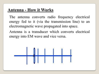
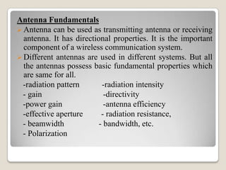
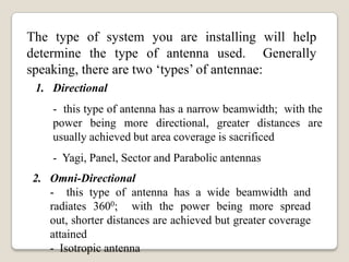
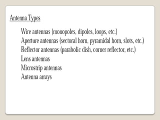
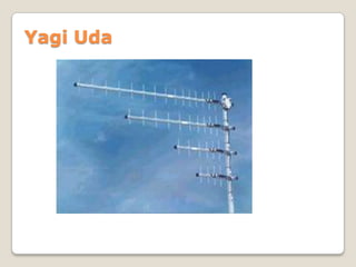
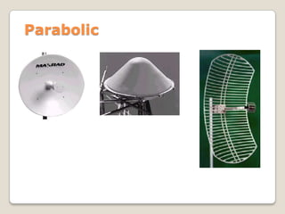
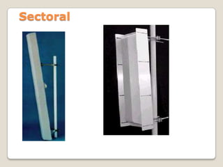
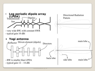
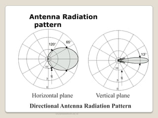
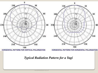
UNIT-I
ANTENNA FUNDAMENTALS
PREPARED BY: BEWNET GETACHEW
Introduction
 The electric charges are the sources of the electromagnetic (EM)
fields. When these sources are time varying, the EM waves
propagates away from the source and the radiation takes place.
 In general, the radiation can be considered as a process of
transmitting energy.
 The radiation of the electromagnetic wave into the space is
effectively achieved by using a conducting or dielectric structure
called antennas or radiators.
 A metallic device used for radiating or receiving radio waves is
called antenna.
 According to IEEE, antenna is defined as a means for radiating or
receiving radio waves. Thus antenna is regarded as a transition
between the free space and transmission line.
 The antenna is a matching device between free space and the
transmission line.
Impedance matching: matches impedance of
transmission line to the intrinsic impedance of
free space to prevent wanted reflection back to
source.
Two main purposes of Antenna
Antenna must be designed to direct the
radiation in the desired direction.
Antenna - How it Works
The antenna converts radio frequency electrical
energy fed to it (via the transmission line) to an
electromagnetic wave propagated into space.
Antenna is a transducer which converts electrical
energy into EM wave and vice versa.
Antenna Fundamentals
 Antenna can be used as transmitting antenna or receiving
antenna. It has directional properties. It is the important
component of a wireless communication system.
 Different antennas are used in different systems. But all
the antennas possess basic fundamental properties which
are same for all.
-radiation pattern -radiation intensity
- gain -directivity
-power gain -antenna efficiency
-effective aperture - radiation resistance,
- beamwidth - bandwidth, etc.
- Polarization
The type of system you are installing will help
determine the type of antenna used. Generally
speaking, there are two ‘types’ of antennae:
1. Directional
- this type of antenna has a narrow beamwidth; with the
power being more directional, greater distances are
usually achieved but area coverage is sacrificed
- Yagi, Panel, Sector and Parabolic antennas
2. Omni-Directional
- this type of antenna has a wide beamwidth and
radiates 3600; with the power being more spread
out, shorter distances are achieved but greater coverage
attained
- Isotropic antenna
dBd and dBi
isotropic radiator
half-wave dipole
2.15dB
eg: 0dBd = 2.15dBi
Yagi Uda
Parabolic
Sectoral
uku@stttelkom.ac.id
• Log periodic dipole array
(LPDA) DipolesTransmission
line
- BW is smaller than LPDA
- typical gain 12 – 14 dBi
Reflector Driven element (dipole)
Directors
• Yagi antenna
Directional Radiation
Pattern
main lobe
main lobeside lobe
back lobe
- very wide BW, with constant SWR
- typical gain 10 dBi
uku@stttelkom.ac.id
Antenna Radiation
pattern
Directional Antenna Radiation Pattern
Horizontal plane Vertical plane
uku@stttelkom.ac.id
Typical Radiation Pattern for a Yagi
uku@stttelkom.ac.id
0
90
180
270 0 -3 -6 -10
-15
-20
-30
dB
0
90
180
270 0 -3 -6 -10
-15
-20
-30
dB
Typical Radiation Pattern for a Sector
uku@stttelkom.ac.id
Pattern
uku@stttelkom.ac.id
Upper Side Lobe
Suppression (dB)
Side lobes
120°
(eg)
Peak
Peak - 10dB
Peak - 10dB
10dB Beamwidth
60° (eg) Peak
Peak - 3dB
Peak - 3dB
3dB Beamwidth
Beamwidth
An antennas polarization is relative to the E-field of antenna.
– If the E-field is horizontal, than the antenna is Horizontally
Polarized.
– If the E-field is vertical, than the antenna is Vertically Polarized.
Polarization
No matter what polarity you choose, all antennas in the same RF
network must be polarized identically regardless of the antenna
type.
Polarization
Vertical Horizontal
Vertical Polarization:
The electric field is vertical to the ground (In the maximum
gain direction)
Horizontal Polarization:
The electric field is parallel to the ground (In the maximum gain
direction)
Polarization Requirements for various frequencies
Polarization may deliberately be used to:
– Increase isolation from unwanted signal sources (Cross
Polarization Discrimination (x-pol) typically 25 dB)
– Reduce interference
– Help define a specific coverage area
Horizontal
Vertical

Antenna chapter 1

  • 1.
  • 2.
    Introduction  The electriccharges are the sources of the electromagnetic (EM) fields. When these sources are time varying, the EM waves propagates away from the source and the radiation takes place.  In general, the radiation can be considered as a process of transmitting energy.  The radiation of the electromagnetic wave into the space is effectively achieved by using a conducting or dielectric structure called antennas or radiators.  A metallic device used for radiating or receiving radio waves is called antenna.  According to IEEE, antenna is defined as a means for radiating or receiving radio waves. Thus antenna is regarded as a transition between the free space and transmission line.  The antenna is a matching device between free space and the transmission line.
  • 3.
    Impedance matching: matchesimpedance of transmission line to the intrinsic impedance of free space to prevent wanted reflection back to source. Two main purposes of Antenna Antenna must be designed to direct the radiation in the desired direction.
  • 4.
    Antenna - Howit Works The antenna converts radio frequency electrical energy fed to it (via the transmission line) to an electromagnetic wave propagated into space. Antenna is a transducer which converts electrical energy into EM wave and vice versa.
  • 10.
    Antenna Fundamentals  Antennacan be used as transmitting antenna or receiving antenna. It has directional properties. It is the important component of a wireless communication system.  Different antennas are used in different systems. But all the antennas possess basic fundamental properties which are same for all. -radiation pattern -radiation intensity - gain -directivity -power gain -antenna efficiency -effective aperture - radiation resistance, - beamwidth - bandwidth, etc. - Polarization
  • 12.
    The type ofsystem you are installing will help determine the type of antenna used. Generally speaking, there are two ‘types’ of antennae: 1. Directional - this type of antenna has a narrow beamwidth; with the power being more directional, greater distances are usually achieved but area coverage is sacrificed - Yagi, Panel, Sector and Parabolic antennas 2. Omni-Directional - this type of antenna has a wide beamwidth and radiates 3600; with the power being more spread out, shorter distances are achieved but greater coverage attained - Isotropic antenna
  • 13.
    dBd and dBi isotropicradiator half-wave dipole 2.15dB eg: 0dBd = 2.15dBi
  • 15.
  • 16.
  • 17.
  • 19.
    uku@stttelkom.ac.id • Log periodicdipole array (LPDA) DipolesTransmission line - BW is smaller than LPDA - typical gain 12 – 14 dBi Reflector Driven element (dipole) Directors • Yagi antenna Directional Radiation Pattern main lobe main lobeside lobe back lobe - very wide BW, with constant SWR - typical gain 10 dBi
  • 20.
    uku@stttelkom.ac.id Antenna Radiation pattern Directional AntennaRadiation Pattern Horizontal plane Vertical plane
  • 21.
  • 22.
    uku@stttelkom.ac.id 0 90 180 270 0 -3-6 -10 -15 -20 -30 dB 0 90 180 270 0 -3 -6 -10 -15 -20 -30 dB Typical Radiation Pattern for a Sector
  • 23.
  • 27.
  • 46.
    120° (eg) Peak Peak - 10dB Peak- 10dB 10dB Beamwidth 60° (eg) Peak Peak - 3dB Peak - 3dB 3dB Beamwidth Beamwidth
  • 50.
    An antennas polarizationis relative to the E-field of antenna. – If the E-field is horizontal, than the antenna is Horizontally Polarized. – If the E-field is vertical, than the antenna is Vertically Polarized. Polarization No matter what polarity you choose, all antennas in the same RF network must be polarized identically regardless of the antenna type.
  • 51.
    Polarization Vertical Horizontal Vertical Polarization: Theelectric field is vertical to the ground (In the maximum gain direction) Horizontal Polarization: The electric field is parallel to the ground (In the maximum gain direction)
  • 54.
    Polarization Requirements forvarious frequencies
  • 57.
    Polarization may deliberatelybe used to: – Increase isolation from unwanted signal sources (Cross Polarization Discrimination (x-pol) typically 25 dB) – Reduce interference – Help define a specific coverage area Horizontal Vertical