Download to read offline
![Vijaykumar H.K et al Int. Journal of Engineering Research and Applications www.ijera.com
ISSN : 2248-9622, Vol. 4, Issue 7( Version 1), July 2014, pp.41-48
www.ijera.com 42 | P a g e
then did not reduce significantly on further addition. Composites with smallest size fly ash particles proved to be better in enhancing strength and relative elongation [1].Kurt Feichtinger, (2006)focused on to compare the properties of identical laminate builds comprising two piles of 1808 E-glass fabric on each side of nominal ½”(12.5mm) thick core materials produced by vacuum-infusion and hand-layup processing. Core materials investigated included pre- coated/decay-resistant end-grain balsa, two densities and two suppliers of cross linked PVC foams, two extruded PET foams variants, an extruded polypropylene honey-comb core, one density of an SAN foam, three densities of polyurethane foam, and a special core comprised of an assembly of low- density polyurethane foam planks filament wound with E-glass roving, bound on both sides with scrim. All the core materials with the exception of the last two types were scrim med and had either knife-cut or saw-cut kerfs. The polyurethane foam cores were not scrim med, but instead were double cut. Characterizations included initial core density, laminated weight per unit area, average thickness and strength and stiffness for both flexural as well as “flat-wise” tensile testing. Significant among the findings of this study were a substantial reduction in overall panel thickness and aerial weight, subtle difference in flexural strength, a significantly lower flexure stiffness, slightly greater flat wise tensile strength, and significantly greater flat wise tensile moduli, for vacuum-infusion processing in comparison to hand lay-up [2].K.N. Shivakumar, (2000) focused on two composite laminated panels and one composite sandwich panel was fabricated using Vacuum Assisted Resin Transfer Molding (VARTM). One laminated panel was fabricated from woven E-glass and vinyl-ester resin, the other two from woven carbon and vinyl-ester resin. The sandwich panel was fabricated from woven E-glass, vinyl-ester resin and PVC foam. The measured fiber volume of the E-glass panel is 42%. The calculated fiber volume of the carbon panel is 50%. Tension, compression and shear test were performed to evaluate the mechanical properties of the composite panels. The measured tensile modulus, ultimate tensile strength and Poisson’s ratio of E-glass panel are 23.03 GPa, 325 MPa and 0.11 respectively. The measured shear modulus of E-glass panel is 3.86 GPa. The measured tensile modulus, ultimate strength and Poisson’s ratio of the carbon panel are 47.51 GPa, 436 MPa, and 0.04 respectively. The measured shear modulus of carbon panel was measured as 2.81 GPa. Three-point and four-point bending test were conducted on sandwich beams machined from the sandwich panel. Predicted beam deflection based on the properties calculated from face-sheet and core properties were in close agreement with the measured values for four points bending, but they were not for three point bending [3].Enrico Papa, (2001) focused on experimental investigation into the mechanical behavior of a composite sandwich conceived as a lightweight material for naval engineering applications. The sandwich structure is formed by a three dimensional glass fiber/polymer matrix fabric with transverse pile interconnecting the skins, the core filled with polymer matrix/glass microspheres syntactic foam; additional glass fiber Reinforced Plastics extra skins are laminated on the external facing of the filled fabric.. This work is part of a broader research investigation aimed at a complete characterization, both experimental and numerical, of the complex mechanical behavior of this composite sandwich [4].Kunigal Shivakumar, (2007) focused on the mechanical and fire resistant properties of a commercial material, U.S Gypsum’s Type X SHEETROCK, commonly used for these types of applications was compared with that type of Eco- Core. The results of this study have initiated that the mechanical properties of the Eco-Core are superior in all aspects, for example the compression strength was about 4x greater, the tension strength 3x greater, and the flexural strength was 8x greater. In addition, the fire resistance is comparable and the density is about 40% less. The details of this research are provided in the paper [5].S K Acharya, P Mishra & S C Mishra, (2008) aimed at processing a composite using fly ash, jute with epoxy resin and to study its weathering behavior on mechanical properties such as flexural strength. The fracture surfaces of the specimen are examined under scanning electron microscope. From the study, it appeared that fiber pullout is the predominant mode of failure. The cracking of the fiber structure was avoided due to adherence of fly ash particles which indicated the increase in strength of interfacial bonding. It concluded that this composite can be successfully used as a structural material in household and automobile application and as low cost building material [6].Kulkarni SM, Kishore, (2002) Compressive properties of epoxy composites reinforced with fly ash and fibers, which have differing aspect ratios, are studied. Retention of strength and modulus are observed for a greater range of fiber volume fractions following fly ash introduction into the system. A slight decrease in density was also observed when fly ash content was higher, making these composites with materials of differing aspect ratio bearing reinforcement systems suitable in weight specific applications. The investigations showed that strength decrease is larger in fiber-bearing samples compared with only ash- bearing samples. This decrease was ascribed to the tendency of fibers to bunch. When the ash filler was introduced, this tendency of fibers to cluster appears to be reduced, resulting in increased strength and modulus. Further attempts are made to analyze these](https://image.slidesharecdn.com/g047014148-140909000015-phpapp02/75/Analysis-of-the-Flexure-Behavior-and-Compressive-Strength-of-Fly-Ash-Core-Sandwiched-Composite-Material-2-2048.jpg)
![Vijaykumar H.K et al Int. Journal of Engineering Research and Applications www.ijera.com
ISSN : 2248-9622, Vol. 4, Issue 7( Version 1), July 2014, pp.41-48
www.ijera.com 43 | P a g e
interactions of fibers and fillers through observations made on the surfaces of failed samples by scanning electron microscopy [7] .Thomsons J L, (2000) effect of fibre strength and diameter on the balance of mechanical properties of glass reinforced polyamide 6,6. The results show that the elastic properties of injection molded short glass fiber reinforced polyamide 6,6 are not strongly influenced by fiber diameter in the 10-17 micron range. The ultimate properties of these composites (strength and Izod impact) showed a clear dependence on fiber diameter and the presence of high strength S-2 glass® fibers. Tensile elongation, tensile and flexural strength, and unnotched Izod impact all decreased significantly over the 10-17 micron diameter range. Notched Izod impact showed a small but significant increase over the same range. Addition of 20% w/w of S-2 glass® to the 17 micron E-glass resulted in an 8% improvement in the fiber contribution to composite strength [8] Shah Khan M.Z. 2000 use of glass reinforced polymeric (GRP) composites as structural materials in naval mine countermeasure surface ships. Sea mines when detonated emit underwater shock waves, which could impart severe loading to a naval ship structure, and there are attempts to model the response of a ship structure to this loading.. An experimental program was therefore undertaken to determine the response to increasing strain rates of a number of GRP composites analogous to the actual structural materials. Compressively applied strain rates ranging from 10/s to 101/s and loading rates ranging from 2 to 1000 kN/s were achieved using a servo-hydraulic test machine. Specimens in the form of solid cylinders and cubes having dimensions of 10 mm by 10 mm were used and results are presented showing the effect of strain rate on the maximum strain, maximum strength and elastic modulus. The effect of loading rate on the fracture toughness of the composites was determined using notched three- point-bend specimens [9]. III. METHODOLOGY
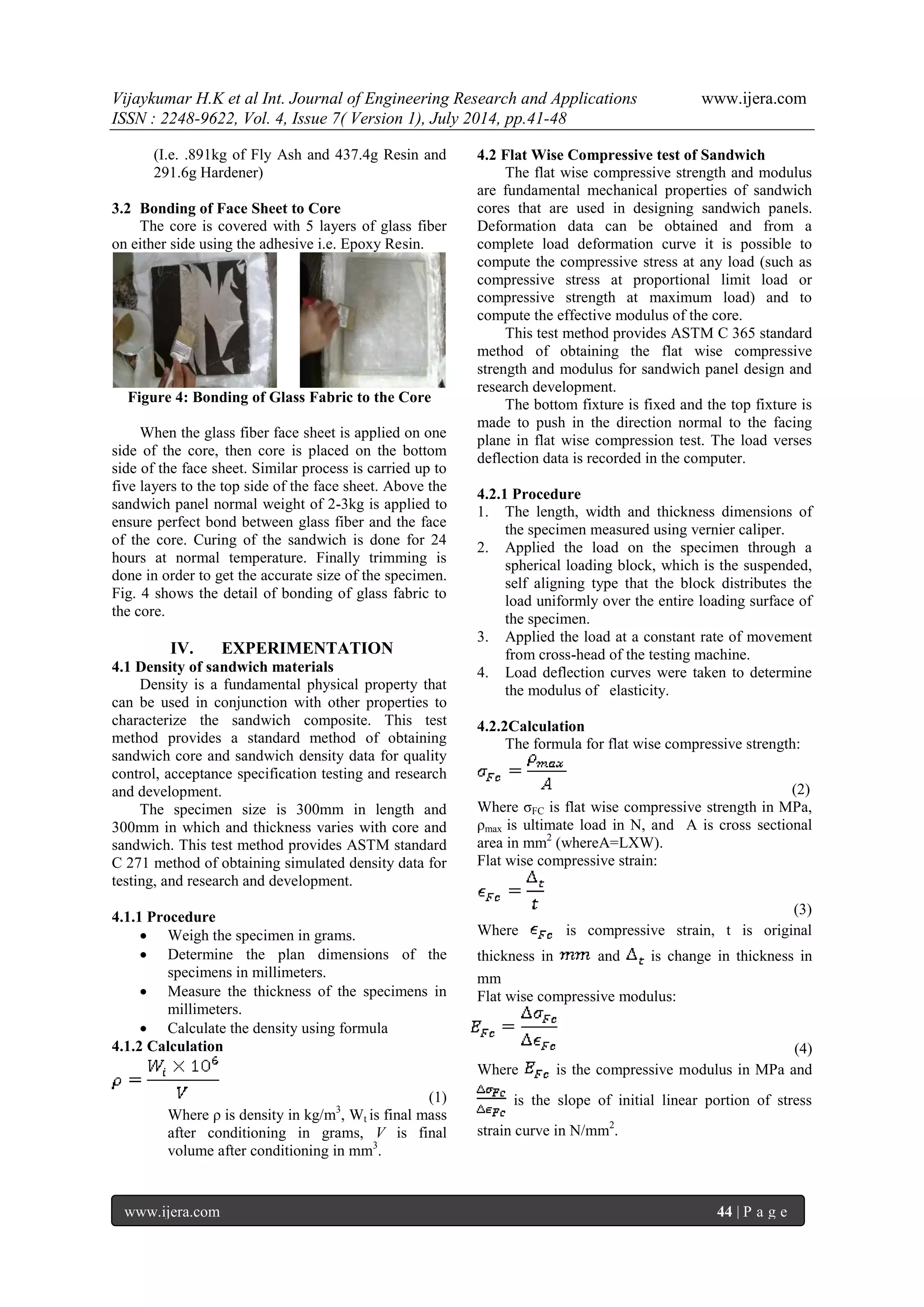
3.1 Preparation of core As per ASTM standard rule C271, the manufacturing technique is carried out. The technique used here is HAND LAYUP technique A mild steel square frame of dimension (304mm*304mm*12.5mm) is first fabricated. Aluminum foil is wrapped to it, so that the core can be easily removed after curing as shown in Fig.1
Figure 1: Wrapping of Aluminum foil to the Frame Some amount of fly ash is taken & measured as per requirement. Similarly, resin & hardener are measured for the required quantity. The measured fly ash is mixed with the measured hardener & resin as shown in Fig.2 Figure2: Mixing of Measured Fly Ash, Resin and Hardener After mixing, the mixture of fly ash, resin & hardener are put into the frame Fig.3 Figure 3: Filling the mixture into the Aluminium covered Frame Next step is to allow the added up mixture to cure for 8-12 hours. After curing, the final product is obtained. Different proportions of fly ash and epoxy resins are carried out, namely
65% by wt. of Fly ash and 35% by wt. of Epoxy resin
(I.e. 1.027 kg of Fly Ash and 331.8g Resin and 221.2g Hardener)
60% by wt. of Fly ash and 40% by wt. of Epoxy resin
(I.e. 1.050kg of Fly Ash and 330g Resin and 220g Hardener)
55% by wt. of Fly ash and 45% by wt. of Epoxy resin](https://image.slidesharecdn.com/g047014148-140909000015-phpapp02/75/Analysis-of-the-Flexure-Behavior-and-Compressive-Strength-of-Fly-Ash-Core-Sandwiched-Composite-Material-3-2048.jpg)
![Vijaykumar H.K et al Int. Journal of Engineering Research and Applications www.ijera.com
ISSN : 2248-9622, Vol. 4, Issue 7( Version 1), July 2014, pp.41-48
www.ijera.com 48 | P a g e
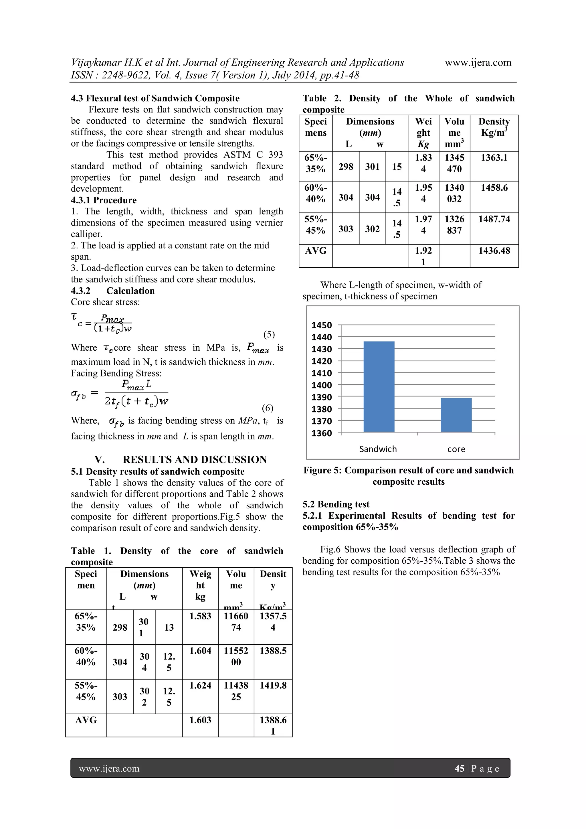
Table 6 Experimental Results Flat Wise Compression test
Specimen
Dimension (mm) L w t
Max Load (kN)
Max Stress (MPa)
Max Strain (%)
Modulus of Elasticity (MPa)
65%- 35%
75
75
15
784.8
139.52
40
399.12
60%- 40%
75
75
14.5
882.9
156.96
48.3
562.40
55%- 45%
75
75
14.5
735.75
130.8
34
580.55
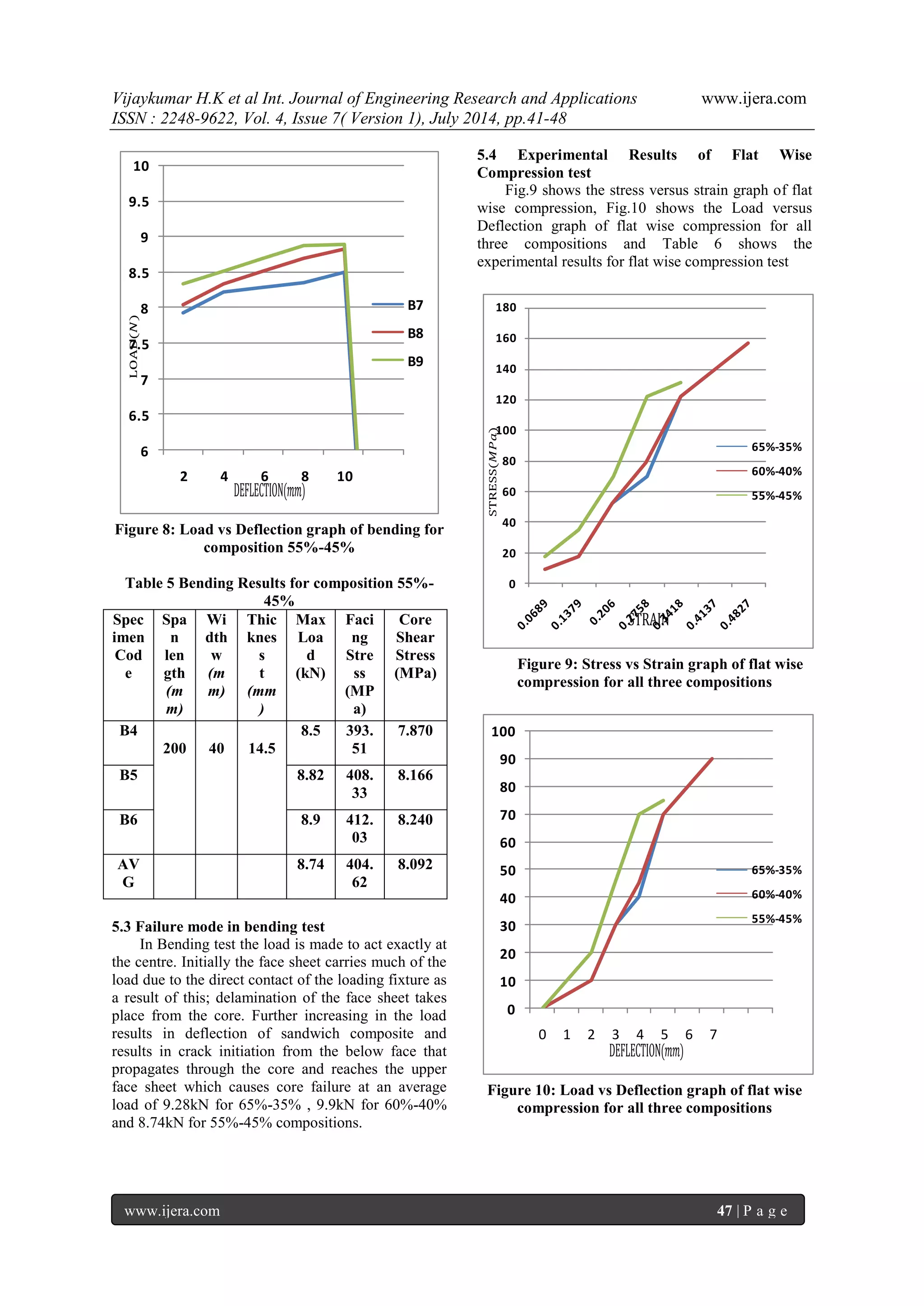
5.5 Failure mode in flat wise compression test Failure occurs in flat wise compression causes the crack propagation at the center of the core that will result in crushing of the core resulting in bulging at the edges of the sandwich. Similar type of failure is observed in all the specimens. As the load increases the sandwich thickness will reduces. The max average load which can withstand the sandwich composite under flat wise compression is 784.8kN, 882.9kN and 735.75kN for 65%-35%, 60%-40% and 55%-45% by wt. of fly ash and epoxy resin respectively.
VI. CONCLUSION
A process for core made from fly ash a waste product of combustion from thermal power plants has been developed using epoxy resin and binder and set of two facing of glass fiber face sheet were bonded above and below of the Epoxy- fly Ash core. The experimental investigations carried by conducting different test for 65%-35%, 60%-40% and 55%-45% by wt. of fly ash and epoxy resin sandwich composite specimen respectively. 60%-40% specimen shows better results in the entire test carried out i.e. Bending and Compression test. With the addition of fly-ash in epoxy resin –fly-ash composite the compressive strength has been found to increase with increase in fly ash particles. This increase is attributed to hollowness of fly-ash particles & strong interfacial energy between resin & fly-ash. After reinforcing glass fiber both compressive & impact strength has been increased due to energy absorbed in fiber pull out. Finally, we came to know that the material has a high compressive strength, high impact strength and these can be applied and replaced to such areas where it needs a good compressive strength like wood applications, flooring, ceiling and other constructions.
REFERENCES [1] Ahmad and Mahanwar, “The effect of fly ash as filler on the mechanical properties of HDPE”, Int J. Adv. Manuf. Technol., vol. 41 2010 [2] Kurt Feichtinger, “The properties of identical laminate builds comprising two piles of 1808 E-glass fabric”, Journal of Mechanical Engineering 2006. [3] K.N. Shivakumar, “Fabrication of two composite laminated panels and one composite sandwich using Vacuum Assisted Resin Transfer Molding (VARTM)”, Int J. Adv. Manuf. Technol., vol. 22, 2000. [4] Enrico Papa, “Experimental investigation into the mechanical behavior of a composite sandwich”, Journal of Mechanical Engineering 2001. [5] Kunigal Shivakumar, “The mechanical and fire resistant properties of a commercial material”, Journal of Materials Processing Technology, 137, 2007 [6] S K Acharya, P Mishra and S C Mishra, “Effect of environment on the mechanical properties of fly ash-jute polymer composite”, International Journal of composites,vol17 ,December 2008. [7] Kulkarni SM, Kishore, “Compressive properties of epoxy composites reinforced with fly ash and fibers”, Journal of Materials Processing Technology, 129, 2002. [8] Thomsons J L, “Effect of fibre strength and diameter on the balance of mechanical properties of glass reinforced polyamide”, Journal of Mechanical Engineering 2000. [9] Shah Khan M.Z, “Use of glass reinforced polymeric (GRP) composites”, Journal of ITU, vol. 3, no. 6, 2000.](https://image.slidesharecdn.com/g047014148-140909000015-phpapp02/75/Analysis-of-the-Flexure-Behavior-and-Compressive-Strength-of-Fly-Ash-Core-Sandwiched-Composite-Material-8-2048.jpg)

This document summarizes research on analyzing the flexural and compressive strength of composite materials with fly ash cores sandwiched between glass fiber face sheets. Three compositions of fly ash and epoxy resin were tested as core materials: 65%-35%, 60%-40%, and 55%-45%. The 60%-40% composition showed the best results for flexural and compressive strength testing. Density, flat-wise compressive strength and modulus, and other mechanical properties were evaluated based on ASTM standards. Previous literature on similar sandwich composites and on using fly ash and fibers in epoxy is also summarized.


![11.[1 10]shear strength study of rc beams retrofitted using vinyl ester bonded](https://cdn.slidesharecdn.com/ss_thumbnails/11-1-10shearstrengthstudyofrcbeamsretrofittedusingvinylesterbonded-120512235418-phpapp02-thumbnail.jpg?width=640&height=640&fit=bounds)
![11.[1 10]shear strength study of rc beams retrofitted using vinyl ester bonded](https://cdn.slidesharecdn.com/ss_thumbnails/11-1-10shearstrengthstudyofrcbeamsretrofittedusingvinylesterbonded-120512235346-phpapp02-thumbnail.jpg?width=640&height=640&fit=bounds)


