Downloaded 454 times

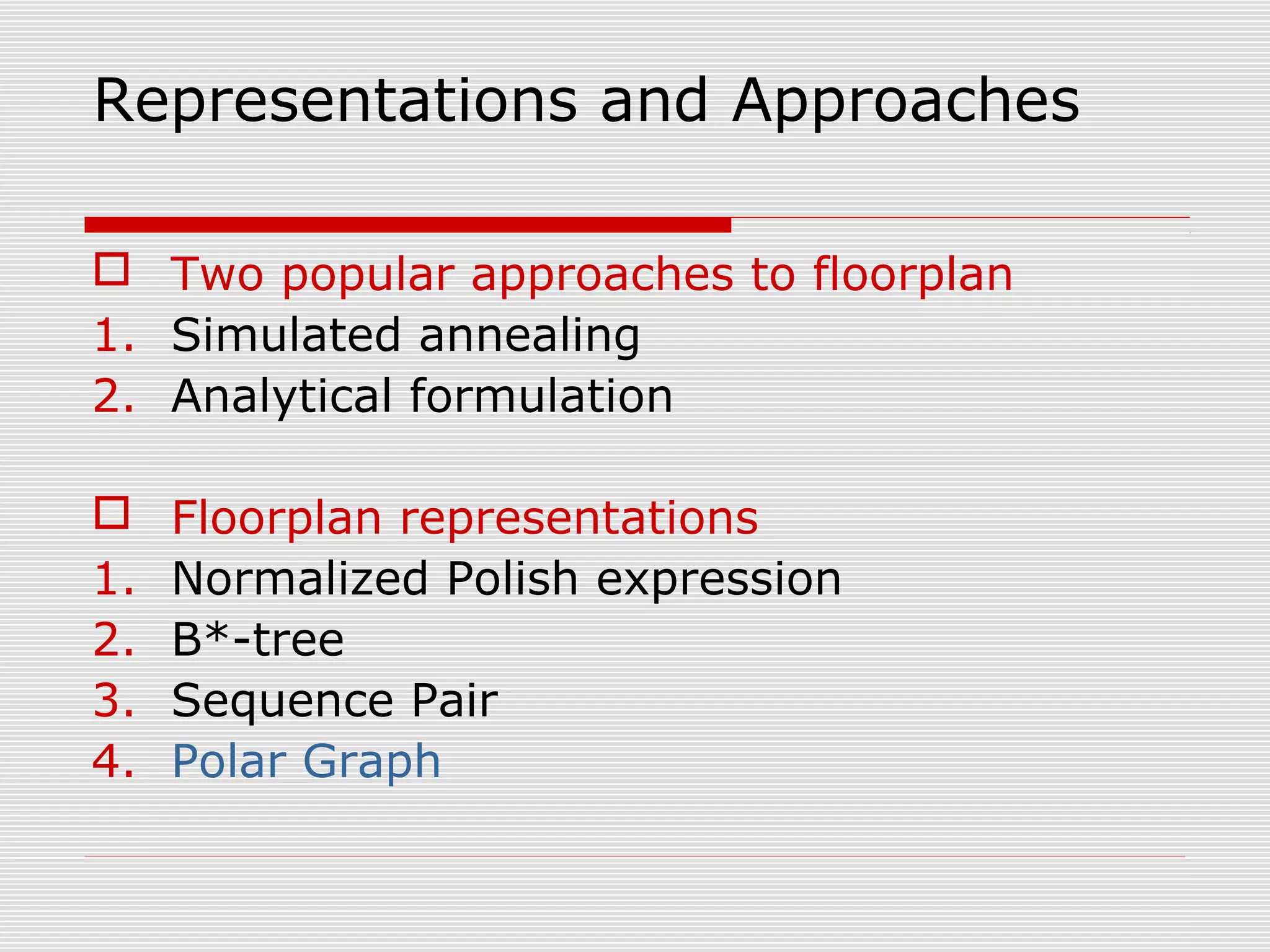
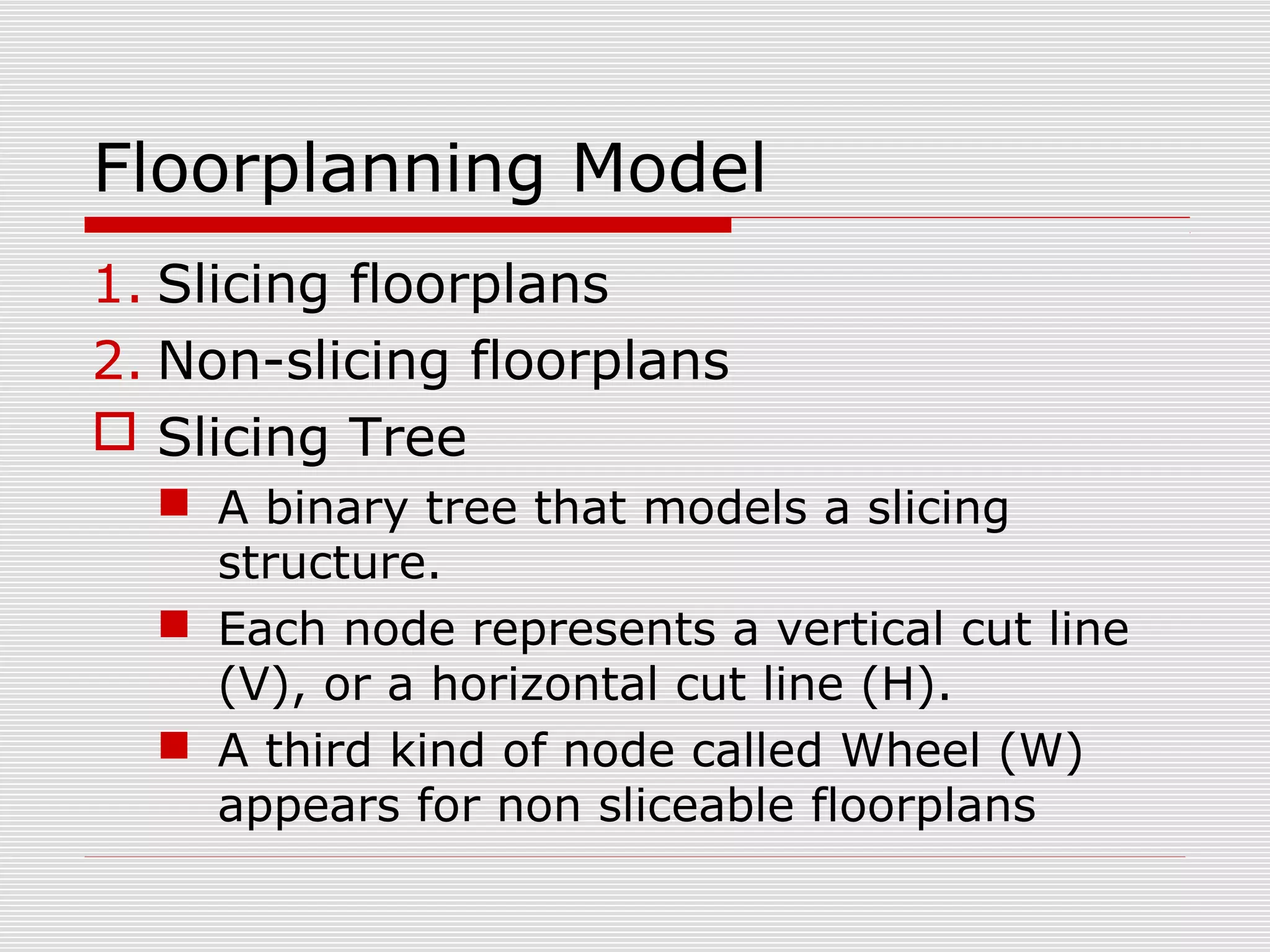
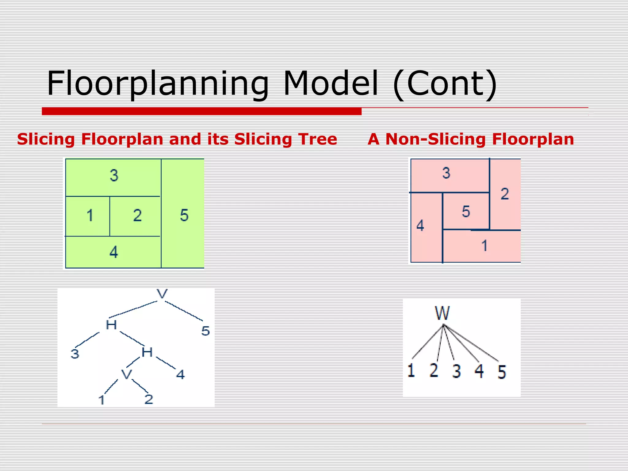
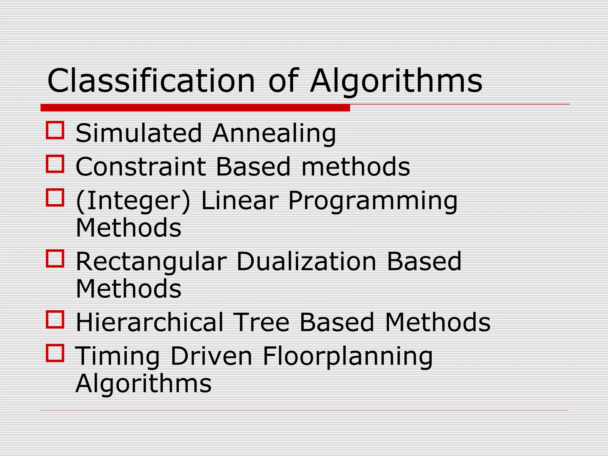

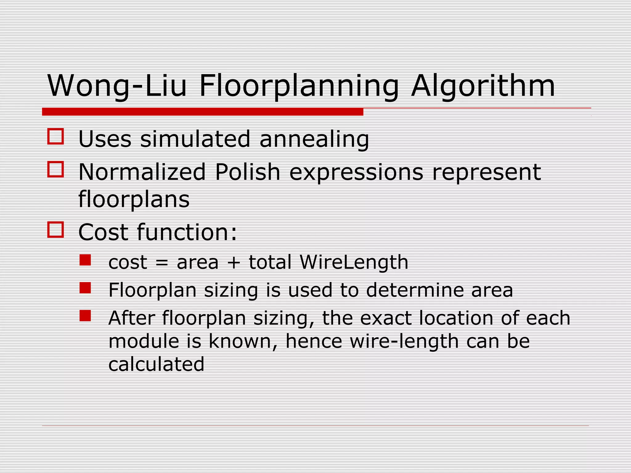
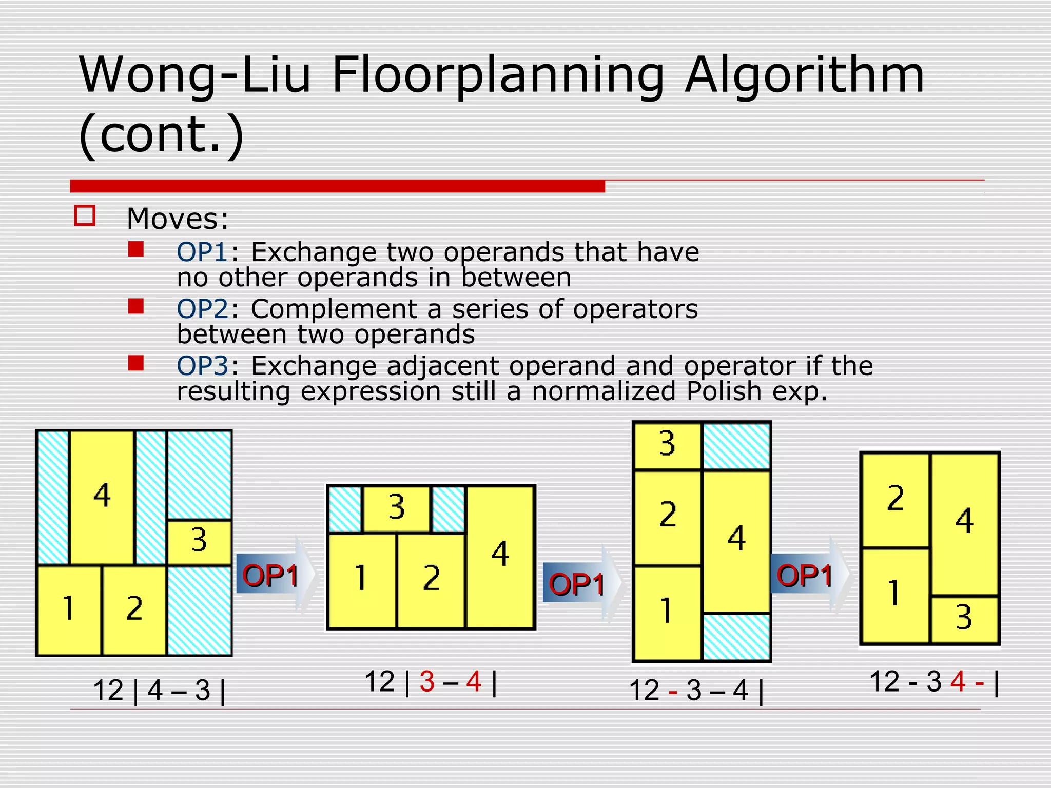


This document provides an overview of floorplanning in chip design. Floorplanning involves block placement, pin assignment, design partitioning, and other tasks. It aims to optimize chip area, wirelength, timing, and routability. Representations like sequence pairs and algorithms like simulated annealing are used. Floorplanning is important for estimating metrics early in design and improving subsequent steps like routing. It can eliminate guesswork and risks from hierarchical flows.


![Coded Agents – with UiPath SDK + LangGraph [Virtual Hands-on Workshop]](https://cdn.slidesharecdn.com/ss_thumbnails/codedagentsdeck-251215155422-5497c599-thumbnail.jpg?width=640&height=640&fit=bounds)


