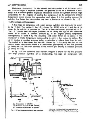
This document discusses air compressors and their uses. It describes the main types of air compressors - reciprocating and rotary. Reciprocating air compressors operate similar to reciprocating engines, using pistons inside cylinders to compress air. Rotary air compressors compress air through the rotation of impellers or blades inside a casing. The document focuses on reciprocating air compressors and their components. It explains the operation of single-stage and two-stage reciprocating air compressors through diagrams and equations. Intercooling between stages brings the compression process closer to isothermal, reducing the work required.

![344 ELEMENTS OF HEAT ENGINES Vol.l
neither of these conditions can be fulfilled and the actual compression will be between
isentropic and isothermal.
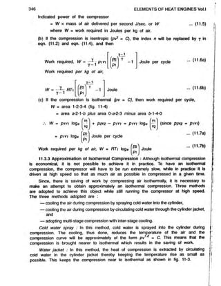
11.3.2 Isothermal Compression Versus Isentropic Compression : The slope of
the compression curve, represented by the law pt/1 = C, depends upon the value of
the index n. A large value of n will give comparatively a steeper curve. The law for
an isothermal or hyperbolic compression is pv = C, where the value of index n is
unity.The law for an isentropic compression is pvy = C. Since the value of y for air
is 1.4,the isentropic curve will be steeper than isothermal curve. Figure 11-3 shows
curves representing an isentropic compression (1-2’) and an isothermal compression
(1-2"). The middle curve (1-2) shows curve, which is obtained in actual practice. The
curve is polytropic (pi/1 = C) having a value of n nearly equal to 1-3 for the water
cooled cylinder.
The isentropic work required to be done per cycle
on the air is represented by the area 4-1-2’-3 (fig. 11-3).
If the compression carried out had been isothermal, the
slope of the compression curve would be less than that
of isentropic and the isothermal work done would be
represented by the area 4-1-2"-3 which is evidently less
than the isentropic work done represented by the area
4-1-2-3. Therefore, it follows that an isothermal com-
pression is economical and efficient, since less work is
required to carry it out, while an isentropic compression
requires more amount of work to be supplied. Compres-
sion curve with values of index n between 1 and 1.4
will fall within the isothermal and isentropic curves. Thus,
it will be seen that the work required for compression
and delivery of air per cycle decreases as the value of
Fig. 11 3. Effect of nature of compression p decreases,
curve on work required for compression.
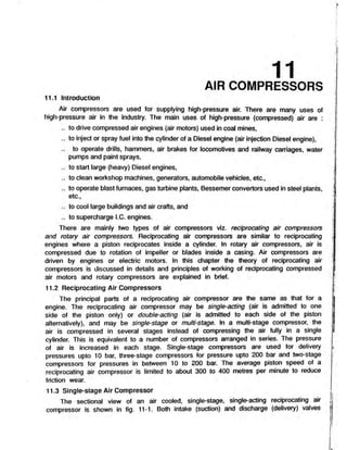
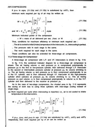
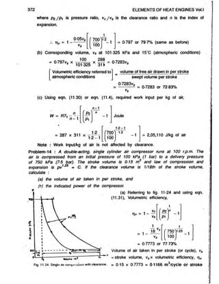
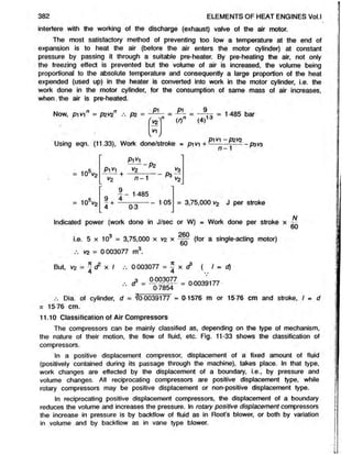
The theoretical indicator diagram for a single-stage compressor without clearance
is shown in fig. 11-4. Let p i in N/m2 (newtons per square metre) or Pa (pascals) and
*3 represent initial
C o m p ressed air
discharge to receiver
c
0
Q
.
Piston driven
from external
so u rce
V s / / / / / u r n
PV-. constant
^cJuu^u
h Y H
E==—1
a
- V ,-------
b
Volum
e
Fig. 11-4. Single-stage air compressor without clearance.
vy in m
condition of the air before
compression, and pz in
N/m = Pa, the final
delivery pressure after
compression, Then,
(a) Work required to
be done on the air W,
per cycle assuming com-
pression curve to be
polytropic,i.e., pt/* = C, is
given by area 1-2-3-4 of
fig. 11-4.
Now area, 1-2-3-4 = area 0-a-2-3 plus area a-2-1-fc minus area £
>
-1-4-0
P2V
0—
Pi V]
= p2V2+ ^ 2
- ; ^ - p i V i](https://image.slidesharecdn.com/aircomprosser-220211190851/85/Air-comprosser-3-320.jpg)
![352 ELEMENTS OF HEAT ENGINES Vol.l
W =
n
n -1
n-1
P?
L V
-1
n
n -1
RTz
n - 1
P3
n
n -1
RT3
n - 1
P4
-1
-1
Joule .. (11.14b)
c
P
H
t
v
t
r
y
t
o
f
«
c
»
<
v
»
f tmmu* l
e
u
f
l
H
® < S s)
JM
.RpitlonJ
• •
thro* Hr
<
7
-
A T
«
u
c
t
>
o
n
^
.M il.. 1
vOlvf
I*
I
f p
f e n
i
« f
LP
.
p
i
s
t
o
n
■ucfton
Volvo
I J
t
f
W
o
l
f
f
•>- .
■8*.9
e. •.
it:'*-
st
o;.t .
i t
t
i .
V
tfn
i f 3
A!
OfOtn cocks
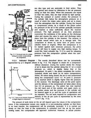
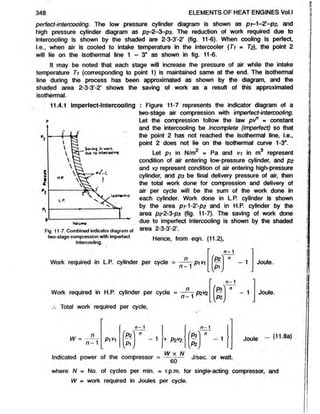
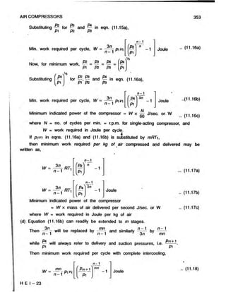
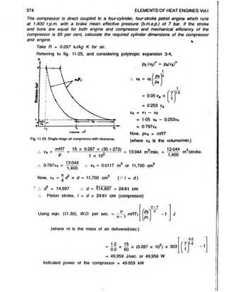
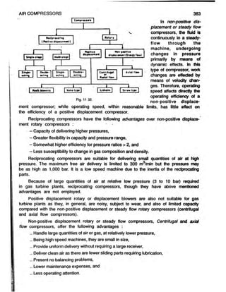
Fig. 11-8. Arrangement of three-stage air compressor
with intercoolers.
to t*
Dull*
V
o
lw
m
o
Fig 11-9. Indicator diagram of three-stage
compression with perfect intercooling.
(b) When intercooling is perfect, ptVi = P2V
2 - P3V
3 Hfe 11-9).
Substituting pivi lor p2v2 and P3V
3 in eqn. (11.14a), work required per cycle,
W
n - 1 n - 1 n - 1
n
pi v
n - 1
fpz n
+
(f*) n
+
n
- 3 Joule
[p i J W w _
... (11.15a)
If p/Vf in eqn. (11.15a) is substituted by mRTh then work required per kg air may
be written as,
n - 1 n - 1 n - 1
= n
~. RT
n - 1
' Pz'
[ p i j
n
+ 'pa'
[pz]
n
+
f Pa ' n
- 3 Joule
.. (11.15b)
(c) Work required is minimum when
Pz _ 03 _ Pa
Pi “ Pz ~ P3](https://image.slidesharecdn.com/aircomprosser-220211190851/85/Air-comprosser-11-320.jpg)
![All the expression derived above for work required refer to the work actually done
or required to be done onthe air, and the power derived from these expressions will
be referredto as indicated power or air power.
11.5.1 Advantages of multi-stage compression : The advantages of multi-stage
compression are as follows :
- Reduction in power required to drive the compressor owing to compression being
approximated to isothermal,
- Better mechanical balance of the whole unit and uniform torque,
- Increased volumetric efficiency as a result of the lower delivery pressure in the
L.P. cylinder clearance space,
- Reduced leakage loss owing to reduced pressure difference on either sides of
the piston and valves,
- Less difficulty in lubrication due to the lower working temperature, and
- Lighter cylinders.
11.6 Air Compressor Terminology
The following terminology should be well understood before attempting to estimate
the performance of the air compressor.
Free air delivered is the volume of air delivered under the conditions of temperature
and pressure existing at the compressor intake, i.e., volume of air delivered at surrounding
air temperature and pressure. In the absence of any given free air conditions, these
are generally taken as 1 01325 bar and 15‘C.
Capacity of a compressor is the quantity of the free air actually delivered by a
compressor in cubic metres per minute.
Piston displacement is the volume in cubic metre (m ) obtained asthe product of
the piston area in m2 and the piston stroke in metre.
Displacement per minute is the product of the piston displacement and working
strokes per minute. For multi-stage compressors, the displacement is based on low-pressure
cylinder only, since it determines the amount of air passing through the other cylinder.
Indicated power or air power is the power determined from the actual indicator
diagram taken during a test on the compressor. It is calculated in the same manner
as is done in the case of a steam engine and internal combustion engine.
Shaft or brake power is the power delivered to the shaft of the compressoror
the power required to drive the compressor. The compressor may be driven by an
engine or an electric motor.
[Shaft or brake power] - [Air or indicated power] = [Friction power]
, „ . . . „. . Air (indicated) power
and Mechanicalefficiency, rim = o. - . —.-, --------
1 1 Shaft (brake) power
Isothermalpower of acompressor is calculated from the theoretical indicator diagram
drawn on the basis of an assumption that the compression is isothermal.
(a) Referring to eqn. (11.7a) for a single-stage compressor without clearance,
354 ELEMENTS OF HEAT ENGINES Vol.l
Isothermal work required per cycle, W = p vi loge'( *
Pi Jou,e .. (11.19a)](https://image.slidesharecdn.com/aircomprosser-220211190851/85/Air-comprosser-13-320.jpg)
![356 ELEMENTS OF HEAT ENGINES Vol.l
y -1
PiV-1
Thus, for a single-stage air compressor,
l v *
Y~1
-1 Joule per cyde
..(11.24a)
Adiabatic (isentropic) power = pi v
Y - 1
P2
Y -1
[ P lj
X £ J/sec. or W 24b)
where A/ = no. of cydes per min.
■ . * __. „ . Isothermal power in watts
Isothermal efficiency = ,---------- . —
Indicated or actural power in watts
Overall isothermal efficiency or
Compressor efficiency .
Isothermal power_
Shaft power or brake power required to]
drive the compressor j
pi vi loge
N „
*6 0
Shaft power or brake power required in watt to drive the compressor
where N = no. of cydes per min.
Isentropic efficiency or ideal
adiabatic efficiency
Isentropic power in watt
Shaft power required in watt
(11.25a)
(11.25b)
Y - 1
P1V1
Y - 1
P?
P1
1
N „
X 60 (11.26)
Shaft power or Brake power required in watt to drive the compressor
where N = no. of cydes per min.
Volumetric efficiency of an air compressor is the ratio of the adual volume of the
free air at standard atmospheric conditions discharged in one delivery stroke, to the
volume swept by the piston during the stroke. The standard atmospheric conditions
(S.T.P.) is actually taken as pressure of760 mm Hg (1 01325 bar) and temperature
15‘C in this connection. Thus,
. Volume of free air delivered per stroke .. (11.27)
Volumetric efficiency = — ;-----------zz— -------- r izr~
Volume swept by piston per stroke
The value of volumetric efficiency varies between 70 to 85 per cent according to
the type of compressor.
The volumetric efficiency decreases as the dearance volume increases. Other factors
that lower the volumetric efficiency are :
- Valve leakage, specially at the inlet valve,
- Obstruction at inlet valves,
- Piston ring leakage, which allowsair to pass from one side of the cylinder to
the other,
- Heating of air by contact with hot cylinder walls, and](https://image.slidesharecdn.com/aircomprosser-220211190851/85/Air-comprosser-15-320.jpg)
![AIR COMPRESSORS 357
- Very high speed of rotation.
With the decrease of volumetric efficiency, the capacity (quantity of free air delivered)
of the compressor decreases.
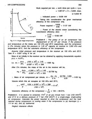
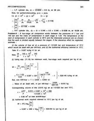
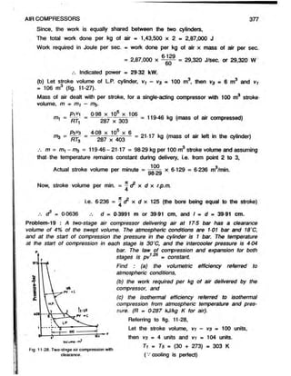
Problem-1 : A single-cylinder, single-acting reciprocating air compressor has a cylinder of
24 cm diameter and linear piston speed of 100 metres per minute. It takes in air at 100
kPa (100 kN/m2) and delivers at 1 MPa ( 1 MN/rrP), Determine the indicated power of
the compressor. Assume the law of compression to be pv
ture of air at inlet is 288 K. Neglect clearance effect.
1.25
■ constant. The tempera-
Given p i = 100 kPa « 100 x 10 Pa; p2 = 1 MPa = 1,000 kPa - 1,000 x 103 Pa.
P*
Pi
1,000 x 10J 1,000
100 x 10J 100
= 10
Swept volume in m3/min. - - x I x r.p.m.
(where, I - piston strokes in metre, and d=
diameter of the cylinder in metre)
2
It
Swept volume = ^ x
f 24 '
100
/
100 3..
x m /min.
( v piston speed = 2 x I x r.p.m. = 100
metres/min.)
_ . . . 3. 2-261 3.
= 2-261 m /min. = m /sec.
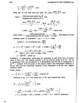
Referring to fig. 11-10 and using eqn. (11.2),
Work required per sec.,
W = pyV] x
n
n - 1
n - 1
S '
L V /
-1 J/sec.
[where, pi is pressure in Parcals (Pa) and volume of air compressed, vi is in m
per sec.]
W = (too x to3) x 2f l X
' ± 000)
100
/
1 2 5 -1
1 25
- 1
= 1,88616 x (1 5848 - 1) - 11,030 J/sec. or 11,030 W
.-. Indicated power of the compressor = 11,030 W i.e. 11-03 kW
Problem-2- : A single-acting, single-stage air compressor developing indicated power of
11 kW, runs at 200 r.p.m. and has a linear piston speed of 100 metres per min. If
the suction pressure and temperature are 100 kPa and 15‘C respectively and delivery
pressure is 1,000 kPa, calculate the dimensions of the compressor cylinder. Assume
the law of compression to be pv125 = constant. Neglect clearance effects.
Referring to fig. 11-10, and considering polytropic compression 1-2, pivin = p2V2n,](https://image.slidesharecdn.com/aircomprosser-220211190851/85/Air-comprosser-16-320.jpg)
![Given: p i = 1 bar = 1 x 10s Pa; p2 - p2 = 7 bar = 7 x 10s Pa; — = -= =
Pi 1x10⁵ 1
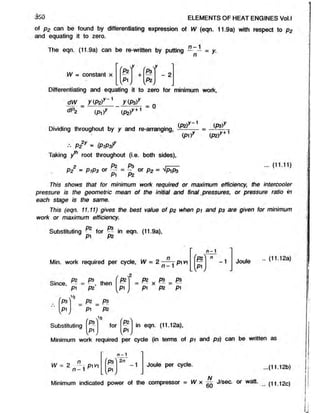
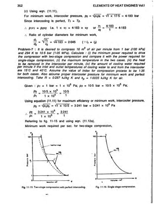
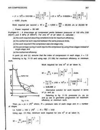
(a) Isentropic compression : '
Referring to fig. 11-12 and using eqn. (11.6a),
isentropic work required per sec.,
360 ELEMENTS OF HEAT ENGINES Vol.l
W = pi vi
Y~ *
I r l
Y
LVP1V
-1 J/sec.
—
— — x (1 x 10®) x —
—
1-4_1 u x lu } x60
'7 X
1
v /
14 -1
14
-1
■ x <
1 x 105) x x [1744-1]
Fig. 11 12. Single stage compression. = 73,750 J/sec. or 73,750 W
/. Power required to drive the compressor
= 73,750 W i.e. 73 75 kW
No heat is rejected during isentropic compression.
(b) Isothermal Compression
Referring to fig. 11-12 ?nd using eqn. (11.7a), isothermal work required/sec.,
fPz
P^
W = pi V) log< = (1 x 10⁵) x ~ x loge
= (1 x 105) x x 1-9459 = 55,080 J/sec. or 55,080 W
60
Required power input = 55,080 W i.e. 55-08 kW
In isothermal compression, as the temperature remains constant, there is no change
in internal energy and the entire work of compression, i.e. 55-08 kJ/sec. is rejected to
jacket cooling water. Heat rejected during isothermal compression = 55-08 kJ/sec.
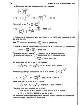
Problem-6 : A two-stage air compressor delivers 145 m3 of free air per hour. The
pressure and temperature in the cylinder at the start of compression are 1 bar and
34'C respectively. The diameter of the low-pressure cylinder is twice that of the high
pressure cylinder. The air enters the high-pressure cylinder at a temperature of 40’C
and is then compressed to 17-5 bar, the law of compression being pv1 « constant
for both stages. Neglecting the effects of clearance, estimate :■ (a) the intercooler
pressure, (b) the air power required, and (c) the ratio of cylinder diameters for minimum
work making the usual assumptions regarding the intercooler conditions.
The free air conditions are 101325 bar and 15'C. Take R = 0287 kJ/kgK for air.
(a) Since, the diameter of L.P. cylinder is twice that of theH.P. cylinder, the ratio
of L.P. to H.P. cylinder volumes will be 4, i.e. vt = 4v^
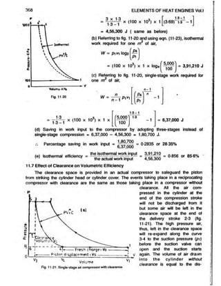
Applying characteristic equations at points of suction in L.P. and H.P. cylinders,](https://image.slidesharecdn.com/aircomprosser-220211190851/85/Air-comprosser-19-320.jpg)
![P1V
1 P2V2
AIR COMPRESSORS
i.e.
1 x 4v2 P2 x vz
h T2
Intercooler pressure, pz =
(34 + 273) (40 + 273)
1 x 4 x 313
307
= 4 078 bar
(b) Using characteristic equation for free air conditions, pv - mRT
i.e. (1 01325 x 10s) x —Jf = m x (0287 x 103) x (15 + 273)
60
m = 2 963 kg of air per minute.
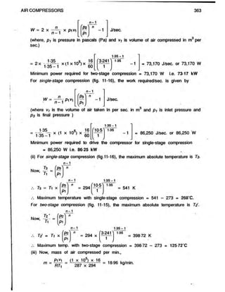
Referring to fig. 11-13, and using eqn. (11.8b) for imperfect intercooling,
. . . . . . . ... fWork required in] , [Work required ini
Total w o* required per kg of air, W = | Hp ^ |jnder j +j LP J
.-. W = RTi - —
n —1
t
c
1
|
c
[p i J
+ RTz
n
n - 1
n- 1
P3^ n
v /
-1
= R
n
n - 1
n- 1 n - 1
V
"P2^
W
n
- 1 + r2 M
W
n
- 1
= 0-287 x 307
122
1 2 2 -1
= 290 kJ per kg of air
' 4-078
1
v
0-22
>1-22
- 1 + 313
0 22
f I 7.5 l-22
4078
- 1
o.ggo
Work done per sec. = W x m = 290 x —
—- = 14-32 kJ/sec.
60
Air power = 14-32 kW
Fig. 11-13. Two-stage compression with
imperfect intercooling
Fig. 11-14.](https://image.slidesharecdn.com/aircomprosser-220211190851/85/Air-comprosser-20-320.jpg)
![366 ELEMENTS OF HEAT ENGINES Vol.l
Isothermal efficiency = Workreqwed when compression is isothermal
isothermal efficiency Actual work required to be done on the air
408-454
= 07734, or 77 34%
528-145
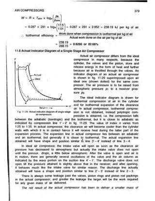
Problem-10 : The following particulars apply to a two-stage, single-acting air compressor :
Stroke = 28-5 cm; Low pressure cylinder = 23 cm;
Final pressure = 25 bar; Intermediate pressure - 5 bar;
Temperature of air leaving the intercooler = 35'C
If the air drawn in the compressor is at 1 bar and 15'C, find the power expended
(used) in compressing air when running at 350 r.p.m. Assume law of compression as
pv1
'3 - constant for both stages.
Swept volume of the L.P. cylinder, vi = ^ & x I = ^
f 23
100
x = OOf189 m3.
100
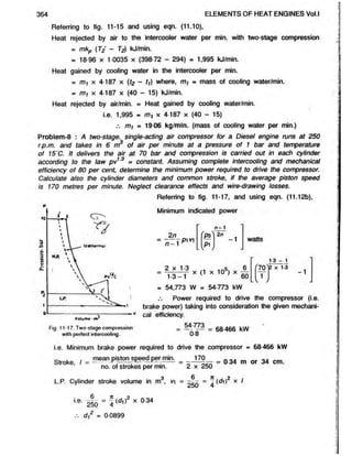
Referring to fig. 11-18, and considering polytropic compression 1-2',
p vn = pzvz'n
f p r
n m 1-3
vz ' — X V j=
Oil
X
n - 1
Again,
Tz'
T i = Ti x
PZ
Pi
&
K
n - 1
= (15 + 273) x
NoW
, P2V2^
Tz Tz'
0-3
1-3
= 417 3 K
Fig. 11-18. Two-stage compression with imper-
fect intercooling.
vz = T2 x = (35 + 273) x
= 0 00254 m3.
Referring to fig. 11-18 and using eqn. (11.8a* for two-stage compression with
imperfect intercooling,
-r » . , .,J, M/ [Work done in] . fWork done in]
Total work required per cycle, W = | L p cy||nder j +| H p
n - 1
= P1V1
"
n - 1
n ' Pz n
-1
n -1
Ip1J
+ P2H2
n
n - 1
/ _
P3
w
1](https://image.slidesharecdn.com/aircomprosser-220211190851/85/Air-comprosser-25-320.jpg)
![AIR COMPRESSORS 369
placement volume corresponding to full stroke vs. However with clearance, the volume
of fresh air drawn into the cylinder is only va corresponding to stroke 4-1.
Thus, the effect of clearance in a compressor is to decrease the amount of fresh
air that can be drawn into the cylinder during the suction stroke. Therefore, there is a
considerable reduction in the volumetric efficiency of the compressor due to clearance.
In practice the clearance volume is limited to, two or three per cent of the displacement
or swept volume (va) of the piston.
11.7.1 Expression for work done : Assuming that the value of the index n for
expansion curve 3-4 (fig. 11-21) is the same as that for the compression curve 1-2,
and making use of eqn. (11.2),
Net work required per cycle, W = area 1-2-3-4 = area 1-2-5-6 minus area 5-3-4-6
•mi n
W = — - pivi
n- 1 n-1
1
c
aT
~ n - P' V
A
n
-1
i
5.
w
n
n - 1
P?
P1
n
n -1
pi va
1
c
--------
1
1
c
w
Joule per cycle. .. (11.28)
It may be noted that eqn.(11.28) is same as eqn. (11.2).
This shows that the work required to compress and deliver the same volume of
air, va (volume of fresh air drawn in the cylinder) in a compressor with clearance, is
same as that required in a compressor without clearance.
In other words, the introduction of clearance does not theoretically increase work
of compression as the work done in compressing theclearance space air will be
regained during the expansion of the clearance air from V
3 to va at the beginning of
the suction stroke.
N
Net work required in = W x — J/sec. or W where N = no. of cycles per min.
» 60
watts
Indicated power of the compressor = ^OOO ^
.. (11.29)
If piva in eqn. (11.28) is substituted by mRTi, then net work required per kg of
air may be written as
W = ——r RT]
n —1
-1
LV
Joule.
n -1
fP?) n
which is same as eqn. (11.4).
Net work required in J/sec.
= W x mass of air delivered per second J/sec. or W
H E I - 24
.. (11.30)](https://image.slidesharecdn.com/aircomprosser-220211190851/85/Air-comprosser-28-320.jpg)
![370 ELEMENTS OF HEAT ENGINES Vol.l
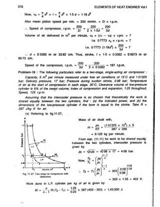
11.7.2 Expression for Volumetric Efficiency : Let vc and vs be the clearance
volume and swept volume respectively of the compressor, p2 - pressure in N/nrP « pa
of air in the clearance space, p i = pressure in N/nr? ■ pa of clearance air at the end
of expansion, and n is the index of expansion.
Referring to fig. 11-21, Volume of clearance air at the end of re-expansion,
M
n
Vc
W
H [p i J
v4 = v3
The volume of fresh charge of air, va = vi - V
4
1 i
va = v - vc
= vs- vc
P2
pi
= Vs + Vc - Vc
_P2
P1
[ V V1 m Vs + V$
1
( * )
n
- 1
l^J
Volumetric efficiency, iv =
vi ~ va
Vs
Va
Vs
V s -V c
1
/ » ]
n
- 1
p i J
Vs
1
^
Vc (p z )
n
-1
vs [p iJ
(11.31)
Thus, the volumetric efficiency depends upon the pressure ratio, pz /p and the
clearance ratio, vc/v s.Volumetric efficiency decreases as the pressure ratio increases.
It also decreases as clearance volume (as a percentage of swept volume) increases
or volumetric efficiency decreases as the clearance ratio increases.
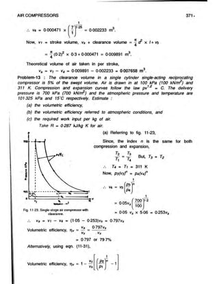
Problem-12 : A compressor has 20 cm bore and 30 cm stroke. It has a linear clearance
of 15 cm. Calculate the theoretical volume of air taken in per stroke when working
0 between pressures of 1 bar and 7 bar. The index
of compression and expansion is same and its
value is 125.
Referring to fig. 11-22,
Clearance volume vc = V
3
va » Area of cylinder x linear clearance.
= - S x linear clearance
4
= J (0-2)2 x 1-5 = 0000471 m3.
100
Considering polytropic expansion (3-4),
P3*3n = P4V4°
Fig. 11-22. Single-stage air compressor with
clearance.
V4 = V3
P4](https://image.slidesharecdn.com/aircomprosser-220211190851/85/Air-comprosser-29-320.jpg)
![AIR COMPRESSORS
(b) Using eqn. (11.28), work required per cycle,
373
IA t ^
W = — T p , v .
n - 1
'P i n
- 1
w
Joule
l v
750
100
= T x (100 x 103) x 0-1166 (7S0^ 125
1-25 —1
= 28,920 Joule per cycle.
Work required in Joules per second
N
= W x (where, N = no. of cycles per min. = 2 x 100 = 200)
= 28,920 x = 96,400 J/sec. or 96,400 W
60
Indicated power of the compressor = 96,400 W or 96-4 kW.
Problem-15 : A single-cylinder air compressor compresses air from 1 bar to 7 bar.
The clearance volume is 2 litres and law of compression and expansion is pv12 =
constant. If the volumetric efficiency of the compressor is 80 per cent, determine : (i)
the stroke volume and (ii) the cylinder dimensions. Assume stroke of the piston equal
Jo diameter of the cylinder.
Here p i = 1 bar, p2 = 7 bar, vc = 2 litres, n - 1-2 and rv = 80 per cent.
Vc
Using eqn. (11.31), Volumetric efficiency, rv = 1 - —
Vs
Pz - 1
Substituting the values, wet get, 0-8 = 1 -
i.e. 0 8 = 1 - - [4 06] or — = - “ p
vs l 1 v, 406
vs
1
( 7 '
1
l v y
0-2
406
1-2
2 x 4 06
Vs = ------- ------
02
7
C
Now, vs = ‘i x cr x d
4
= 40 6 litres = 40 6 x 103 cm.
( v I = d)
i.e. 40 6 x 103 = V
4
d = i f I 0 6 x- = ^51,693-5 = 37 25 cm.
7C
—1
.-. Cylinder diameter, d = 37-25 cm, and piston stroke, I » d - 37-25 cm.
Problem-16 : A single-acting, single-cylinder air compressor is to deliver 15 kg of air
per minute at 7 bar from suction conditions of 1 bar and 30'C. The clearance volume is
5% of the stroke volume and the law of compression and expansion is pv = constant.](https://image.slidesharecdn.com/aircomprosser-220211190851/85/Air-comprosser-32-320.jpg)
![380 ELEMENTS OF HEAT ENGINES Vol.l
air than that handled by the ideal compressor and to require an expenditure of work
in excess of that of the ideal one as shown by greater area.
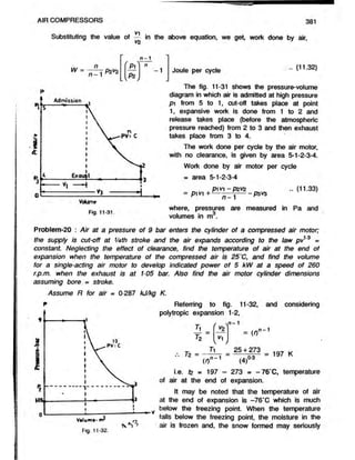
11.9 Reciprocating Compressed Air Motor
Air motor is in effect a reversed air compressor. The compressed air to be used
in an air motor is taken from the compressor reservoir (receiver). The most common
form of compressed air motor is the cylinder and double-acting piston type. The air is
admitted into the motor cylinder through a mechanically operated inlet valve and drives
the piston forward but after a portion of the stroke of the piston has been performed,
the air supply is cut-off and the stroke is completed under decreasing pressure as the
air expands in the cylinder. After the expansion stroke is completed, the air which has
done the work is allowed to escape into atmospheric through a mechanically operated
discharge valve. The return stroke is performed by compressed air acting on the other
side of the piston. A motor of this type works like a reciprocating double-acting steam
engine.
The important application of air motor is the
use in mines where use of electric motor is
dangerous. There will be a fall in the pressure
of air due to friction in the pipe, the fall being
greater, the greater the distance of the air motor
from the compressor reservoir (receiver).
Figure 11-30 shows the pressure-volume
diagram for a compressed air motor (air engine)
in which clearance is neglected. Air is admitted
at high pressure pi from 4-1, cut off takes place
at point 1. From 1 to 2 air expands from pressure
p i to atmospheric pressure p2 and expansive
work is done. The law of expansion is polytropic,
voium
« i.e. pv° m c. Exhaust takes place from 2 to 3.
Fig. 11 30. Compressed air motor without clearance.
The work done per cycle by the air motor with no clearance is given by area
4-1-2-3.
P1V1 —
P2V2
Work done per cycle = p i v + - — pzvz
nPl V1 ~ P l y1 + P1 y1 ~ P * V2 ~ nP z v2 ± P2V
2
n -1
= T T rrfp i^ -P 2V
2 ]
Pi^i
n
n -1
P2V
2
P2 V
2
-1 Joule
But for polytropic expansion 1- 2,
Pivi" = P2*2 S
v2
1
n](https://image.slidesharecdn.com/aircomprosser-220211190851/85/Air-comprosser-39-320.jpg)
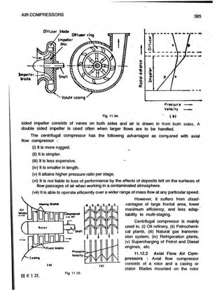
![386 ELEMENTS OF HEAT ENGINES
are moving blades (rotor blades) and blades fixed on the inner face of the casing are
known as stationary blades (stator blades). Air enters the blades axially and also leaves
them in the axial direction as shown in fig. 11-35(a).
An axial flow compressor is designed according to the reaction principle (diffusion
in both rotor and stator). Thus, the rise in pressure through the stage (rotor and stator)
is in general, attributable to both blade rows, moving as well as fixed. As a measure
of the extent to which the rotor itself contributes to this pressure rise, the term “degree
of reaction" is used. Thus, degree of reaction is defined as the ratio of pressure rise
in rotor to the total pressure rise.
A single-stage compressor (one row of moving blades and one row of fixed blades)
does not give appreciable pressure ratio. Axial flow compressor are mostly multi-stage
compressors. Pressure ratio which can be produced per stage of an axial flow compressor
is 1 : 2.
Figure 11-35(a) represents a three-stage, axial flow compressor. The moving blades,
receive the air and increase its velocity, and also act as a diffuser to increase the
pressure, while the fixed blades continue the diffuser action. Figure 11-35(b) shows the
increase in pressure of air during its passage through rotor blades (R) and stator blades
(S).
Axial flow type compressors are given preference over the centrifugal type in the
application of aircraft and industrial gas turbine power plants. This is because axial flow
compressor has a higher efficiency, less frontal area, and is capable of producing higher
pressure ratio on a single shaft by increasing the number of stages. However, the axial
flow compressors run at lower speeds, their weight is greater, have higher starting
torque, are sensitive to any deposit formation on blades, and are complicated as
compared with centrifugal compressors.
Tutorial - 11
1. (a) Estimate the amount of work required for compression of one kg of air for single-stage compression.
(b) What are the uses of high pressure air?
(c) A single-stage, single-acting air compressor deals with 85 m3 of free air per hour at 1 01325 bar and
15‘C. The pressure and temperature in the cylinder during the suction stroke remains constant at 1 bar and
40*C respectively. The index of compression is 1-22 and the delivery pressure is 5-5 bar. If the mechanical
efficiency is 85%, find, neglecting clearance volume, the power required to drive the compressor.
[6-107 kW]
2. A single-acting, single-cylinder, air compressor has a cylinder diameter 18 cm and a stroke of 25 cm. Air is drawn
into the cylinder at 102 kPa (102 kN/m2), 288 K. It is then compressed isentropically to 632 kPa (632 kN/m2).
Find : (a) the power required to drive the compressor if its speed is 120 r.p.m; and (b) the mass of air
compressed per hour. Take y = 1-4 and R = 0-287 kJ/kg K for air. Neglect clearance effects.
[3-112 kW; (b) 56 54 kg/hr ]
3. It is desired to compress 15 m3 of air per minute at 100 kPa (100 kN/m2) and 297 K to 700 kPa (700 kN/m )
in a single-stage, single-acting air compressor. Calculate the power required to drive the compressor if the
compression is :
(a) Isothermal.
(b) Polytropic with index n - 1-3, and
(c) Isentropic.
Take y = 1-4 for air. Neglect clearance effects.
[(a) 48 648 kW; (b) 61 533 kW; (c) 651 kW]](https://image.slidesharecdn.com/aircomprosser-220211190851/85/Air-comprosser-45-320.jpg)
![AIR COMPRESSORS 387
4. (a) A single-stage, single-acting air compressor is belt driven from an electric motor at 400 r.p.m. The cylinder
diameter is 15 cm and stroke is 18 cm. The air is compressed from 1 05 bar to 7-5 bar and the law of compression
is pv13 = constant. Find the power of the motor, if the transmission efficiency is 97% and the mechanical efficiency
of the compressor is 90%. Neglect the clearance effects.
[6 354 kW]
(b) A single-cylinder, double-acting air compressor is of 24 kW. The law of compression is pv12 = constant.
The air is compressed from 1 bar to 8 bar. The compressor runs at 200 r.p.m. and average piston speed
may be taken as 160 m/min. Find the dimensions of the cylinder required. Neglect the effect of clearance.
[d = 21-47 cm; I = 04 m]
5. (a) Define volumetric efficiency of a compressor.
(b) Find the diameter and stroke of a single-stage, double-acting air compressor from the following data :
Capacity * 20 m of free air per minute at atmospheric pressure and temperature; Delivery pressure = 7-5
bar; Inlet pressure = 1 bar; Inlet temperature = 32*C; Atmospheric pressure = 1 01325 bar; Atmospheric
temperature = 15*C; Speed = 300 r.p.m.; Index of compression = 1-3; Stroke : bore = 0-9 : 1.
Also find the indicated power of the compressor. Neglect clearance effects.
[d m 36-99 cm; I = 33 291 cm; 91-753 kW]
6. A two-stage, single-acting air compressor draws air at 1-05 bar and temperature of 16’C. The air is compressed
in the L.P. cylinder to a pressure of 5-25 bar. After compression, the air is cooled in the intercooler at constant
pressure to a temperature of 30*C, before being taken to H.P. cylinder from which it is delivered at 20 bar. The
compression is carried out each cylinder according to the law pv135 = C. Find the indicated work required in kJ
to compress one kg of air. Take R - 0-287 kJ/kg K for air. Neglect clearance.
[304 92 kJ]
7. What are the conditions for obtaining maximum efficiency in the case of a two-stage reciprocating air compressor ?
A two-stage, single-acting air compressor deals with 5-75 m3 of air per minute under atmospheric conditions.
It delivers air at 40 bar. The compressor runs at 300 r.p.m. The stroke is equal to L.P. cylinder diameter.
Assuming complete intercooling and compression in each stage according to the law py*35 = C and mechanical
efficiency of 85 per cent, calculate the cylinder diameters and minimum power required to drive the compressor.
Assume atmospheric conditions as 1-01325 bar and 15‘C. Neglect clearance.
[dLp. = 29 cm; <to.P. = 11-56 cm; 53-758 kW]
8. A two-stage, single-acting air compressor takes in 3 m3 of air per minute at atmospheric pressure of 1 bar abd
temperature of 288 K. It delivers air at 35 bar (3-5 MPa). The compression is carried out in each cylinder according
to the law pv1
'25 = C. Assuming complete intercooling and mechanical efficiency of 80 per cent, calculate the
minimum power required to drive the compressor and the heat carried away from the intercooter per minute by
cooling water. If the inlet and outlet temperatures of the cooling water are 15‘C and 40*C, calculate the amount
of cooling water required per minute. Also compare the volumes of the two cylinders. Neglect clearance effects.
Take R = 0-287 kJAtg K and kp = 1-0035 kJ/kg K for air.
[26-688 kW; 44793 kJ/min.; 4 28 kg/min.; 5-916]
9. What is the object of compressing air in stages?
Derive an expression for the minimum work required to compress and deliver 1 kg of air in a two-stage
compressor. State carefully the assumptions made.
10. What are the advantages of multi-stage compression ?
Determine the minimum driving power required for three-stage compression from 1-05 bar to 42 bar if the
delivery is 4-5 m3 of free air per min. Compression in each stage is carried out according to law pv 3 =
constant. Suction temperature is 21‘C and mechanical efficiency is 80%. Take free air conditions as 1-01325
bar and 15‘C. The air compressor is single-acting. Neglect clearance.
[41 346 kW]
11. A three-stage, single-acting air compressor with perfect intercooling deals with 23 m3 of air per minute at 1-01325
bar and 288 K. The L.P. cylinder suction pressure and temperature are 1 bar and 305 K and the final delivery
pressure is 25 bar. If the stage pressures are in geometric progression and index of compression in each stage
is 1 35, find the power required to drive compressor. Also find the heat rejected to the intercoolers per minute
and isothermal efficiency of the compressor. Neglect clearance. Take R = 0-287 kJ/kg K and Kp= 1-0035 kJ/Kg K
for air.
[152 3 kW; 2,760 kJ/min; 86 86%]](https://image.slidesharecdn.com/aircomprosser-220211190851/85/Air-comprosser-46-320.jpg)
![12. What is meant by the term ‘perfect cooling’ ?
A three-stage, single-acting compressor has perfect intercooling. The pressure and temperature at the end
of suction stroke in the L.P. cylinder is 1-01325 bar and 15’C respectively. The delivery pressure is 70 bar.
Compression in each stage is carried out according to pv12 = C, and 8-5 m9 of free air (1-01325 bar and
15’C) are delivered per min. If the work done is minimum, calculate :
(i) the L.P. and I.P. delivery pressures,
(ii) the ratio of cylinder volume, and
(iii) the indicated power of the compressor.
Neglect clearance
[(i)4-158 bar, 17-059 bar; (ii) 16-835 : 4-103 : 1; (iii) 68-73kW]
13. A three-stage, single-acting air compressor works between 1-05 bar and 42 bar. For one cubicmetre of air
taken in, calculate:
(i) the indicated work required in kJ for maximum efficiency,
(ii) the isothermal work required in kJ between the same pressure limits,
(iii) the indicated work required if the compressor were of one-stage only,
(iv) the isothermal efficiency ofthe compressor, and
(v) the percentage saving in work required due to using three-stages instead ofone.
In parts (i) and (iii), assume the index of compression, n = 1-25.
Neglect clearance.
[(i) 438-64 kJ; (ii) 387-34 kJ; (iii) 572-78 kJ; (iv) 88-3%; (v) 23-42%]
14. (a) Explain the effect of clearance on the performance of air compressor.
(b) Explain that volumetric efficiency depends on clearance volume and pressure ratio for a single-stage
compressor.
The clearance volume in a single-stage, single-acting air compressor is 5% of the swept volume. Air is
drawn ‘
m at constant pressure of 1 bar and temperature of 43*C. Compression and expansion follow the
la«*£V125 = constant. The delivery pressure is 6-5 bar and atmospheric pressure and temperature are
1-01325 bar and 15*C respectively. Estimate.
(a) the volumetric efficiency.
(b) the volumetric efficiency referred to atmospheric conditions, and
(c) the work required per kg of air.
Take R = 0-287 kJ/kg K for air.
[(a) 82 65%; (b) 74-34%; (c) 205 87 kJ/kg]
15. A single-acting, single-cylinder air compressor compresses air from 1 bar to 6-5 bar. Compression and expansion
follow the law pv125 = constant. The clearance volume is 1 litre. If the volumetric efficiency of the compressor
is 80%, calculate the stroke volume. If the ratio of diameter of cylinder to stroke of piston is 1-5, calculate diameter
of the cylinder and stroke of the piston.
(0 0173 m3; 24 52 cm; d = 36-78 cm]
16. A single-acting, single-cylinder air compressor runs at 100 r.p.m. The air is compressed from 1 to 8 bar. The
stroke volume is 0-125 m3 and the law of compression and expansion is pv1'3 = C. If the clearance volume is
5% of the stroke volume, calculate :
(i) the volumetric efficiency,
(ii) the volume of air taken in per minute, and
(iii) the indicated power of the compressor.
l(i) 80-245%; (ii) 10-031 m3
/min.; (iii) 44-55 kWJ
17. In an air compressor, show that cylinder clearance does not affect the theoretical work required to compress
and deliver one kg of air, provided that delivery and suction pressures remain constant, and that the indices of
compression and expansion have the same value.
A single-stage, single-acting air compressor is required to deliver 6 m of free air per minute at a mean
piston speed of 165 m per min. The air is to be compressed from an initial pressure of 1-05 bar to deljvery
pressure of 7 bar and index of compression and expansion is assumed to be 1-3. Assuming stroke of piston
to be 1-25 times the bore of the cylinder, clearance volume to be 1/15th of the swept volume per stroke
and suction pressure and temperature to be equal to atmospheric pressure and temperature, find : (i) the
volumetric efficiency, (ii) the speed, and (iii) the bore and stroke.
[(i) 78%; (ii) 191 64 r p.m.; (iii) d = 34-47 cm, I = 43 08 cm)
388 ELEMENTS OF HEAT ENGINES](https://image.slidesharecdn.com/aircomprosser-220211190851/85/Air-comprosser-47-320.jpg)
![AIR COMPRESSORS 389
18. A single-stage, double-acting air compressor has a stroke volume of 0 06 m3 and a clearance volume of 0 003
m3. Find its volumetric efficiency referred to atmospheric conditions (1-01325 bar and 15’C) and the mass of air
delivered per hour when the speed is 200 r.p.m. The suction pressure is 0-92 bar and suction temperature is
50*C and the delivery pressure is 6 bar. Also determine the indicated power of the compressor. Assume com-
pression and expansion law as pv135 = constant. Take R = 0-287 kJ/kg K for air.
[68-77%; 1,2139 kg/hr; 75476 kW]
19. A single-acting, single-stage air compressor is required to compress 5 kg of air per minute from 0-95 bar and
30’C to a pressure of 7-6 bar. The clearance volume is 5% of the stroke volume and the index of both the
expansion and compression curves is 1-25. If the stroke and bore are equal and compressor runs at 120 r.p.m.,
find the size of the cylinder.
Take R = 0-287 kJ/kg K for air. [d = I = 39 53 cm]
20. A two-stage, single-acting air compressor has to deal with 3 m3 of air per minute under atmospheric conditions
(1-01325 bar and 15*C) at 220 r.p.m. and delivers at 85 bar. Assuming complete intercooling between the stages,
find the minimum power required to drive the compressor, the cylinder diameters and the common stroke. Assume
a piston speed of 165 m per min. mechanical efficiency of compressor as 80% and volumetric efficiency of 85%
for each stage. Compression in each cylinder is carried out according to the law pv19 = constant. Neglect
clearance.
[36 553 kW; dip. = 23 34 cm; ckp. = 7 712 cm; I = 37 5 cm]
21. In a two-stage, single-acting air compressor, the delivery pressure is 17-5 bar and the suction pressure is 1
bar. The temperature at the start of compression in each stage is 30*C and the index of compression in each
stage is 1 25. The clearance volume of the low-pressure cylinder is 5 per cent of the swept volume and the
diameter of low-pressure cylinder is 0-8 of the stroke..The mass of air delivered by the compressor is 5 kg/min.
and the intercooler pressure has the ideal value. Find :
(a) the bore of the L.P. cylinder if the speed of the compressor is 110 r.p.m., and
(b) the indicated power of the compressor.
The expansion of the clearance air may be assumed to follow the same law as that for compression.
[(a) 35-59 cm; (b) 23-988 kW]
22. The following particulars apply to a two-stage, single-acting air compressor: Stroke = 25-4 cm; Low-pressure
cylinder diameter = 29-2 cm; Final pressure = 25 bar; Intermediate pressure = 5 bar; Temperature of air leaving
the intercooler * 35'C.
If the volume of air drawn in the compressor and measured at 1 bar and 15*C, is 80% of the low-pressure
cylinders swept volume, find the power expended (used) in compressing the air when running at 250 r.p.rri.
Assume law of compression as pv13 = C in each stage. [22-88 kW]
23. Plot actual and theoretical indicator diagrams of a single-stage reciprocating air compressor. Discuss why they
differ.
24. Describe briefly the working of an air motor (compressed air engine), Where it is used ?
Air at pressure of 8-5 bar enters the cylinder of an air motor; the supply is cut-off at quarter stroke and
expands according to the law pv = constant. Neglecting the effect of clearance, find the temperature at
the end of expansion when the initial temperature erf air is 30’C. Calculate also the cylinder volume for a
single-acting air motor to develop 3-7 kW power at a speed of 250 r.p.m., when exhaust is at 1-05 bar.
Take R = 0 287 kJ/kg K for air. [-86-5*C; 2,604 9 cm3]
25. What are rotary compressors? Differentiate between blowers and compressors. What are axial flow compressors ?
26. (a) How are compressors classified ?
(b) Distinguish between :
(i) Reciprocating and rotary compressors, and
(ii) Positive displacement and non-positive displacement compressors.
27. (a) Differentiate between a fan, a blower, and a compressor.
(b) What is the difference between centrifugal and axial flow compressors ?
28. Sketch and describe the operation of a single-stage centrifugal compressor ?
29. (a) What are the advantages and disadvantages of centrifugal compressors ?
(b) Sketch and describe the operation of an axial flow air compressor.
(c) What are the advantages and disadvantages of axial flow compressors as compared with centrifugal
compressors ?](https://image.slidesharecdn.com/aircomprosser-220211190851/85/Air-comprosser-48-320.jpg)


