INTRODUCTION
Software maintenance isthe last stage of
software life cycle.
After the product has been released, the
maintenance phase keeps the software up to
date with environment changes &changing user
requirements.
It consumes about 40-70% of the cost of the
entire life cycle.
Typically, the development cycle for a software
product spans 1 or 2 years, while the
3.
WHAT IS SOFTWAREMAINTENANCE
Software maintenance is a very broad activity that includes
error corrections, enhancement of capabilities, deletion of
obsolete capabilities, and optimization.
it is modification of software product after delivery to
correct faults, to improve performance or other attributes
or to adapt the product to a modified environment.
4.
NEED FOR MAINTENANCE
Correcterrors.
Change is user requirement with time.
Changing hardware and software environment.
To improve system efficiency.
To modify the components.
To optimize the code to run faster.
5.
AIM OF SOFTWAREMAINTENANCE
To correct errors.
To enhance the software by changing it’s
function
To update the software.
To adapt software to cope with changes in the
environment.
OF SOFTWARE
MAINTENANCE
Change controlboard :The change control board
reviews and approves all change request.
The board may deny a request, recommend a
modified version of the change, or approve the
change as submitted.
Change request summaries :The status of change
requests and software maintenance activities should
be summarized on a weekly or monthly basis.
8.
CONT…
Quality assurance activities:The primary function
of a quality assurance group during software
maintenance is to ensure that software quality does
not degrade as a result of maintenance activities.
Organizing maintenance programmers :Software
maintenance can be performed by the development
team or by members of a separate organization.
9.
CONFIGURATION MANAGEMENT
Configuration managementis concerned with
tracking and controlling of the work products that
Constitute a software product.
During product development, the various milestone
reviews result in formal acceptance of work products
such as the project plan, the requirements
specifications, the test plan, the user’s manual, the
design documentation, and the source code.
10.
CONT…
Configuration management databases:software
tools to support configuration management include
configuration management data bases and version
control library systems.
Version control libraries :A version control library
may be part of a configuration management data
base, or it may be used as a stand-alone tool.
The Revision control system (RCS) is one example of
a version control library system.
OBJECTIVES
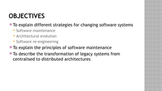
To explaindifferent strategies for changing software systems
Software maintenance
Architectural evolution
Software re-engineering
To explain the principles of software maintenance
To describe the transformation of legacy systems from
centralised to distributed architectures
SOFTWARE CHANGE
Softwarechange is inevitable
New requirements emerge when the software is used
The business environment changes
Errors must be repaired
New equipment must be accommodated
The performance or reliability may have to be improved
A key problem for organisations is implementing and
managing change to their legacy systems
15.
SOFTWARE CHANGE STRATEGIES
Software maintenance
Changes are made in response to changed requirements but the
fundamental software structure is stable
Architectural transformation
The architecture of the system is modified generally from a
centralised architecture to a distributed architecture
Software re-engineering
No new functionality is added to the system but it is restructured
and reorganised to facilitate future changes
These strategies may be applied separately or together
16.
PROGRAM EVOLUTION DYNAMICS
Program evolution dynamics is the study of the processes of
system change
After major empirical study, Lehman and Belady proposed
that there were a number of ‘laws’ which applied to all
systems as they evolved
There are sensible observations rather than laws. They are
applicable to large systems developed by large organisations.
Perhaps less applicable in other cases
17.
LEHMAN’S LAWS
Law Description
Continuingchange A program that is used in a real-world environment
necessarily must change or become progressively less
useful in that environment.
Increasing complexity As an evolving program changes, its structure tends
to become more complex. Extra resources must be
devoted to preserving and simplifying the structure.
Large program evolution Program evolution is a self-regulating process.
System attributes such as size, time between releases
and the number of reported errors are approximately
invariant for each system release.
Organisational stability Over a program’s lifetime, its rate of development is
approximately constant and independent of the
resources devoted to system development.
Conservation of
familiarity
Over the lifetime of a system, the incremental change
in each release is approximately constant.
18.
APPLICABILITY OF LEHMAN’SLAWS
This has not yet been established
They are generally applicable to large, tailored systems
developed by large organisations
It is not clear how they should be modified for
Shrink-wrapped software products
Systems that incorporate a significant number of COTS components
Small organisations
Medium sized systems
19.
SOFTWARE MAINTENANCE
Modifyinga program after it has been put into
use
Maintenance does not normally involve major changes to the
system’s architecture
Changes are implemented by modifying existing components
and adding new components to the system
20.
MAINTENANCE IS INEVITABLE
The system requirements are likely to change
while the system is being developed because
the environment is changing. Therefore a
delivered system won't meet its requirements!
Systems are tightly coupled with their environment. When a
system is installed in an
environment it changes that environment and
therefore changes the system requirements.
Systems MUST be maintained therefore if they
are to remain useful in an environment
21.
TYPES OF MAINTENANCE
Maintenance to repair software faults
Changing a system to correct deficiencies in the way meets
its requirements
Maintenance to adapt software to a different operating
environment
Changing a system so that it operates in a different environment
(computer, OS, etc.) from its initial implementation
Maintenance to add to or modify the system’s functionality
Modifying the system to satisfy new requirements
22.
DISTRIBUTION OF MAINTENANCEEFFORT
Functionality
addition or
modification
(65%)
Fault repair
(17%)
Software
adaptation
(18%)
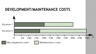
MAINTENANCE COSTS
Usuallygreater than development costs (2* to
100* depending on the application)
Affected by both technical and non-technical
factors
Increases as software is maintained.
Maintenance corrupts the software structure so
makes further maintenance more difficult.
Ageing software can have high support costs
(e.g. old languages, compilers etc.)
MAINTENANCE COST FACTORS
Team stability
Maintenance costs are reduced if the same staff are involved with them for some
time
Contractual responsibility
The developers of a system may have no contractual responsibility for
maintenance so there is no incentive to design for future change
Staff skills
Maintenance staff are often inexperienced and have limited domain knowledge
Program age and structure
As programs age, their structure is degraded and they become harder to
understand and change
27.
EVOLUTIONARY SOFTWARE
Ratherthan think of separate development and maintenance
phases, evolutionary software is software that is designed so
that it can continuously evolve throughout its lifetime
28.
THE MAINTENANCE PROCESS
Systemrelease
planning
Change
implementa tion
System
release
Impact
analysis
Change
requests
Adaptive
maintenance
Corrective
maintenance
Perfective
maintenance
29.
CHANGE REQUESTS
Changerequests are requests for system changes from users,
customers or management
In principle, all change requests should be carefully analysed
as part of the maintenance process and then implemented
In practice, some change requests must be implemented
urgently
Fault repair
Changes to the system’s environment
Urgently required business changes
MAINTENANCE PREDICTION
Maintenanceprediction is concerned with assessing which
parts of the system may cause problems and have high
maintenance costs
Change acceptance depends on the maintainability of the
components affected by the change
Implementing changes degrades the system and reduces its
maintainability
Maintenance costs depend on the number of changes and costs of
change depend on maintainability
CHANGE PREDICTION
Predictingthe number of changes requires and understanding
of the relationships between a system and its environment
Tightly coupled systems require changes whenever the
environment is changed
Factors influencing this relationship are
Number and complexity of system interfaces
Number of inherently volatile system requirements
The business processes where the system is used
35.
COMPLEXITY METRICS
Predictionsof maintainability can be made by assessing the
complexity of system components
Studies have shown that most maintenance effort is spent on
a relatively small number of system components
Complexity depends on
Complexity of control structures
Complexity of data structures
Procedure and module size
36.
PROCESS METRICS
Processmeasurements may be used to assess maintainability
Number of requests for corrective maintenance
Average time required for impact analysis
Average time taken to implement a change request
Number of outstanding change requests
If any or all of these is increasing, this may indicate a decline
in maintainability
37.
ARCHITECTURAL EVOLUTION
Thereis a need to convert many legacy systems from a
centralised architecture to a client-server architecture
Change drivers
Hardware costs. Servers are cheaper than mainframes
User interface expectations. Users expect graphical user interfaces
Distributed access to systems. Users wish to access the system from
different, geographically separated, computers
38.
DISTRIBUTION FACTORS
Factor Description
Business
importance
Returnson the investment of distributing a legacy system
depend on its importance to the business and how long it
will remain important. If distribution provides more efficient
support for stable business processes then it is more likely to
be a cost-effective evolution strategy.
System age The older the system the more difficult it will be to modify
its architecture because previous changes will have degraded
the structure of the system.
System structure The more modular the system, the easier it will be to change
the architecture. If the application logic, the data
management and the user interface of the system are closely
intertwined, it will be difficult to separate functions for
migration.
Hardware
procurement
policies
Application distribution may be necessary if there is
company policy to replace expensive mainframe computers
with cheaper servers. .
39.
LEGACY SYSTEM STRUCTURE
Ideally, for distribution, there should be a clear separation
between the user interface, the system services and the
system data management
In practice, these are usually intermingled in older legacy
systems
LEGACY SYSTEM DISTRIBUTION
Userinterface
Application
services
Database
Character terminals
Legacy system
Desktop PC clients running application
Middleware layer (wrapper)
Legacy system
43.
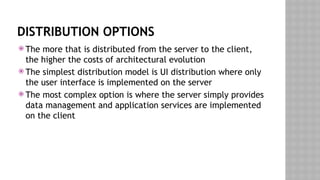
DISTRIBUTION OPTIONS
Themore that is distributed from the server to the client,
the higher the costs of architectural evolution
The simplest distribution model is UI distribution where only
the user interface is implemented on the server
The most complex option is where the server simply provides
data management and application services are implemented
on the client
44.
DISTRIBUTION OPTION SPECTRUM
Increasingcost
and effort
Server: Interaction control
Data validation
Services
Database
Client: Presentation
Server:Database
Server: Services
Database
Client: Presentation
Interaction control
Data validation
Client: Presentation
Interaction control
Data validation
Services
45.
USER INTERFACE DISTRIBUTION
UI distribution takes advantage of the local processing power
on PCs to implement a graphical user interface
Where there is a clear separation between the UI and the
application then the legacy system can be modified to
distribute the UI
Otherwise, screen management middleware can translate
text interfaces to graphical interfaces
46.
USER INTERFACE DISTRIBUTION
Userinterface
Application
services
Database
Desktop PC clients with
GUI interface
Screen management
middleware
Legacy system
Screen descriptions
47.
UI MIGRATION STRATEGIES
StrategyAdv
a nt ages Disadv
a ntages
Im
p lementation
usin
g th e windo
w
mana
g
e ment
sy
s tem
Access t
o all UI f unctions so no
real restric
tions on UI desi
gn
Better UI performance
Platform dependent
May be more diffi cult to ach ie
v
e
interface consistenc
y
Im
p lementation
usin
g a web
browser
Platform independent
Lower trainin
g co sts due to u ser
familiarity with the WWW
Easier to ac
hiev
e interface
consistency
Potentially poo rer UI
performance
Interfac
e de
sign is constrained
b
y th e facilities pro
vid ed b
y we
b
browsers
48.
KEY POINTS
Softwarechange strategies include software maintenance,
architectural evolution and software re-engineering
Lehman’s Laws are invariant relationships that affect the
evolution of a software system
Maintenance types are
Maintenance for repair
Maintenance for a new operating environment
Maintenance to implement new requirements
49.
KEY POINTS
Thecosts of software change usually exceed the costs of software
development
Factors influencing maintenance costs include staff stability, the
nature of the development contract, skill shortages and degraded
system structure
Architectural evolution is concerned with evolving centralised to
distributed architectures
A distributed user interface can be supported using screen
management middleware
50.
REVERSE ENGINEERING
ReverseEngineering is a process of redesigning an existing
product to improve and broaden its functions, add quality and to
increase its useful life.
The main aim of reverse engineering is to reduce manufacturing
costs of the new product, making it competitive in market.
The duplication is done without the aid of drawings, documentation
or computer model.
50
51.
WHY REVERSE ENGINEERING?
The original producer no longer produces the product.
There is inadequate documentation of product.
Some bad features of the product needs to be redesigned.
To update obsolete materials or antiquated manufacturing processes
with more current, less expensive technologies.
51
DIGITIZING
Collecting datafrom physical part.
Used when drawing of object is not available.
Aim is to generate a 3D mapping of the product in the form of
CAD file.
This requires acquisition of surface data, which is large number of
points on the product surface.
For this two types of processes are used: contact and non contact
method.
54
55.
DISCRETIZATION METHOD
Contact methodNon contact method
Requires contact between the
component surface & a measuring tool.
Uses Coordinate Measuring Machine
(CMM), electromagnetic digitizer or
sonic digitizers to get desired
coordinates.
Uses light as the main tool
Uses white light or laser scanners to
scan 3D objects to generate CAD
design.
55
56.
MANIPULATION OF DATA
Basically, after completion of this a CAD model of product is
obtained.
Used to fit a geometry to the large number of points obtained from
digitizing.
The surface can be mathematically defined as algebraic or
parametric surface.
Surface fitting techniques can be of two types: interpolation and
approximation techniques.
56
57.
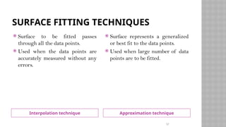
SURFACE FITTING TECHNIQUES
Interpolationtechnique Approximation technique
Surface to be fitted passes
through all the data points.
Used when the data points are
accurately measured without any
errors.
Surface represents a generalized
or best fit to the data points.
Used when large number of data
points are to be fitted.
57
58.
GENERATION OF FUNCTIONALPART
The geometric model obtained, can be used as the basis for variety
of operations.
Operations such as automated process planning, automated
manufacturing, automated dimensional inspection and automated
tolerance analysis.
58
59.
ADVANTAGES OF REVERSEENGINEERING
RE typically starts with measuring an existing
object, so that a solid model can be deduced in
order to make use of the advantages of
CAD/CAM/CAE technologies.
CAD models are used for manufacturing or rapid
prototyping applications.
Hence we can work on a product without having
prior knowledge of the technology involved.
Cost saving for developing new products.
Lesser maintenance costs
Quality improvement
Competitive advantages
59
60.
APPLICATIONS
Manufacturing Field:To create a 3D virtual model of an
existing physical part for use in 3D CAD, CAM, CAE or other
software and to analyze the working of a product.
Medical Field: Imaging, modeling and replication (as a
physical model) of a patient's bone structure
Software engineering: To detect and neutralize viruses and
malware.
60
61.
SOFTWARE RE-ENGINEERING
Softwarere-engineering is concerned with re-
implementing legacy system to make them more
maintainable.
Re-engineering may involve re-documenting the system,
organizing and restructuring the system, translating the
system to more modern programming language and
modifying and updating the structure and values of the
system’s data.
62.
KEY ADVANTAGES ORRE-ENGINEERING
Reduced risk: there is a high risk in redeveloping software
that is essential for an organization. Errors may be made in
the system specification, there may be development
problems etc.
Reduced cost: the cost of re-engineering is significantly less
than the costs of developing new software.
RE-ENGINEERING V/S NEWSOFTWARE
DEVELOPMENT
The critical difference between re-engineering and new
software development (also called forward engineering) is
the starting point for the development. Rather than start
with a written specification, the old system acts as a
specification for the new system.
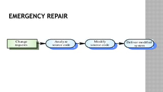
RE-ENGINEERING PROCESS
The inputto the process is a legacy program and the
output is the modularized version of the same program. As
the same time as program re-engineering, the data for the
system may also be re-engineered. The activities in this re-
engineering process are: Source Code Translation,
Reverse Engineering, Program Structure Improvement,
Program Modularization, Data Re-engineering
67.
I SOURCE CODETRANSLATION
Automatically
transla te code
Design translator
instructions
Identify source
code differences
Manually
translate code
System to be
re-engineered
System to be
re-engineered
Re-engineered
system
68.
SOURCE CODE TRANSLATION
The simplest form of s/w re-engineering is program translation
where source code in one programming language is translated to
source code in some other language.
Source code translation is only economically realistic if an
automated translator is available.
In this process source in one programming language is
automatically translated in source code in some other language.
The target language may be an updated version of the original
language(eg. COBOL-74 to COBOL-85) or may be a translated to a
completely different language(eg. FORTRAN to C)
69.
WHY SOURCE CODETRANSLATION?
It may be necessary for the following reasons.
i. Hardware Platform Update: The organization may whish to
change its standard h/w platform. Compilers for the original
language may not be available on the new h/w.
70.
WHY SOURCE CODETRANSLATION?
ii. Staff skill shortages: There may be a lack of trained
maintenance staff for the original language. This is a
particular problem where programs were written in a non-
standard language that has now gone out of general use.
iii. Organizational Policy Changes: An organization may decide
to standardize on a particular language to minimize it
support software costs. Maintaining many copies of old
compilers can be very expensive.
71.
SOFTWARE CONFIGURATION MANAGEMENT
TOOL
ConfigurationManagement Tools
An instance of software is released under one version.
Configuration Management tools deal with –
Version and revision management
Baseline configuration management
Change control management
CASE tools help in this by automatic tracking, version
management and release management. For example, Fossil, Git,
Accu REV.
71
72.
CONFIGURATION MANAGEMENT TOOLS
ChangeControl Tools
These tools are considered as a part of configuration management tools. They
deal with changes made to the software after its baseline is fixed or when the
software is first released. CASE tools automate change tracking, file
management, code management and more. It also helps in enforcing change
policy of the organization.
Programming Tools
These tools consist of programming environments like IDE (Integrated
Development Environment), in-built modules library and simulation tools. These
tools provide comprehensive aid in building software product and include features
for simulation and testing. For example, Cscope to search code in C, Eclipse.
72
73.
CONFIGURAITON MANAGEMENT TOOLS
Prototyping CASE tools essentially come with graphical libraries. In
addition, they provide simulation of software prototype. For example,
Serena prototype composer, Mockup Builder.
Web Development Tools
These tools assist in designing web pages with all allied elements like
forms, text, script, graphic and so on. Web tools also provide live preview
of what is being developed and how will it look after completion. For
example, Fontello, Adobe Edge Inspect, Foundation 3, Brackets.
Quality Assurance Tools
Quality assurance in a software organization is monitoring the engineering
process QA tools consist of configuration and change control tools and
software testing tools. For example, SoapTest, AppsWatch, JMeter.
73
#55 The choice of discretization method is based on speed & performance during digitization and avoidance of damage to the product.
#56 Algebraic function is one which is defined as f(x,y,z)=0 and is for infinite surface whereas parametric function is one which is defined as a finite surface for example: bezier surface, NURBS surface.