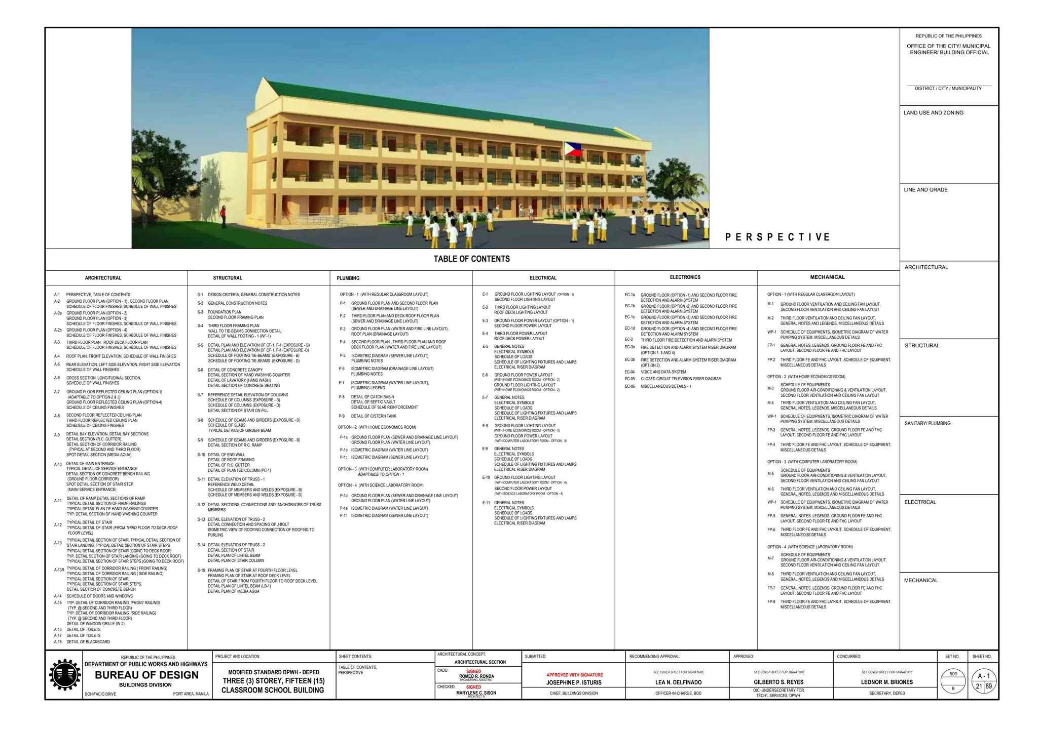
This document contains architectural, structural, plumbing, electrical, and mechanical drawings and details for a proposed three-story, fifteen-classroom school building with four floor plan options. The drawings were prepared by engineers and architects from the Bureau of Design of the Department of Public Works and Highways in the Philippines and include site plans, floor plans, sections, elevations, and construction details. The drawings and specifications are submitted for review and approval by the relevant government authorities.
2000 Del Mar Heights Elementary ModernizationJohnGartman1
This document provides plans and details for the modernization of four permanent buildings and site modifications at Del Mar Heights School in Del Mar, California to improve accessibility. The modernization work includes new mechanical, lighting, data and signal systems, new finishes, partitions and doors, new casework, and modernized plumbing and power systems. The document includes demolition plans, floor plans, roof plans, elevations, sections, schedules and details necessary to communicate the scope and design of the modernization project to contractors and stakeholders.
This document contains architectural, structural, electrical, and sanitary drawings for a proposed three-storey, nine-classroom school building. It includes floor plans, elevations, sections, and details of the building as well as specifications for finishes, schedules, notes, and approvals from the relevant departments. The drawings were prepared by Task Force Engineering, Assessment and Monitoring for the Department of Education and Bureau of Design of the DPWH and follow the standards set forth in Republic Act 545.
This document provides a summary of revisions made to an aircraft characteristics manual for the Airbus A320 and A320NEO. Key changes include adding new illustrations and dimensions for the NEO version, revising existing illustrations and tables, and updating part numbers and effectivity. Over 60 figures and various sections throughout were revised to update information and improve layouts and clarity.
This document contains architectural drawings for a residential design project including a site plan, floor plan, foundation plan, and other details. The floor plan shows the layout of rooms and dimensions on the first and second floors. The foundation plan provides details for the building foundation including rebar layout and specifications for concrete mixes. Notes provide requirements for construction and inspections.
This document provides details for the construction of slab culverts and box culverts, including layout plans, sections, reinforcement details and notes. It includes information on typical abutment and headwall layouts, culvert dimensions, rebar specifications, concrete grades, embedment and protection. Reinforcement schedules are provided for slab and box culvert sections of varying sizes, as well as headwalls, wingwalls and parapets. Construction notes specify requirements for dimensions, materials, cover thickness and refer to other related drawings.
The document provides a code analysis summary for a proposed tenant improvement project at an existing one-story building. The building has a footprint of 159,515sf and total area of 174,568sf. The occupancies include office, production, and warehouse. The analysis finds the building meets egress requirements based on an increased occupant load of 788. Accessibility and parking requirements are identified.
This document contains the detailed engineering design plans for the construction of a multi-purpose building in Barangay Cotta, Lucena City, Quezon, Philippines. The plans include architectural, structural, electrical, plumbing, and mechanical drawings. The multi-purpose building will have a ground floor and second floor with various facilities such as an information area, storage rooms, and toilets. The design was prepared by the Quezon II District Engineering Office of the Department of Public Works and Highways and provides specifications for building materials, finishes, and structural and utility layouts.
This document contains architectural plans and schedules for an interior renovation project. It includes 26 sheets that provide floor plans, reflected ceiling plans, elevations, and schedules for areas like the leasing office, clubroom, exercise studio, fitness center, and more. Electrical, lighting, and finish legends are also included to define symbols and materials used. The project is for a residential building called La Floresta in Brea, California by developer Morgan Group.
This document provides information about renovations to the 5th floor of a 6-story building located at 1314 7th Street in Santa Monica, California. The building has a total area of approximately 82,000 square feet. The renovation plans call for removing some non-bearing walls, repairing flooring and ceilings, adding new partition walls, and installing new furniture, power outlets, and data cabling on the 5th floor, which has an area of 12,830 square feet. Site and floor plans, along with regulatory codes and other project details, are included.
AIRCRAFT CHARACTERISTICS AIRPORT AND MAINTENANCE PLANNING Airbus A320 May2014Amnat Sk
The document provides revisions to the Aircraft Characteristics manual for the Airbus A320 and A320NEO. The revisions include updated illustrations and diagrams, as well as additions of information for the new NEO version. Key changes involve revisions to dimensions, clearances and load information for various aircraft components and systems.
This document contains a site/floor plan layout for a residential property. It includes notes specifying that municipal requirements and those of other authorities must be adhered to. It lists the rooms in the property, including a foyer, bathroom, bedrooms, kitchen, studio, dining/lounge area, laundry, driveway, gardens, and parking. Dimensions are provided for the boundary lines and building lines. The design is the property of the specified architect.
The document contains a drawing index listing 31 structural drawings related to a building construction project. The drawings include plans, sections, and details of foundations, structural elements like beams and columns, floor plans, structural connections, and other building elements. The drawings are dated June 9, 2014 and were provided for approval.
The document contains plans and specifications for the construction of a residential building including:
- A site plan showing the layout of the building structures and surrounding areas.
- Floor plans showing the layout and dimensions of rooms.
- Elevations depicting the exterior views of the building.
- Sections through the building illustrating structural details.
- Schedules with information like material specifications and dimensions of building components.
This document contains plans and specifications for a tenant improvement project for Farmers Insurance Company in an existing building in Agoura Hills, California. It includes a cover page with project information, a sheet index, general notes, contact information, and permit details. The plans include demolition plans, floor plans, reflected ceiling plans, interior elevations, sections, details, schedules, and specifications. It provides documentation for the interior renovation of existing office space into a Chairman's Suite for Farmers Insurance, including new partitions, ceilings, lighting, mechanical, electrical and low voltage systems.
The document appears to be construction plans for a building containing various technical drawings and diagrams including: a table of contents, floor plans, elevations, sections, structural details, plumbing layouts, electrical schematics and specifications. It includes details for foundations, framing, reinforcement, finishes and technical systems like lighting, power, plumbing and more. The plans are for construction of a project in Paliparan, Dasmarinas City, Cavite, Philippines.
03B-MASTER SITE PLAN 03-MASTER SITE (1)Sergio Penton
The document is a site plan for the Liberty Bluff Phase IV development project. It will include 306 single family homes on 139.7 acres, with amenities like parks, retention ponds, and landscaping. The project will be developed in one phase with homes ranging in size from 1700-1900 square feet. The plan shows the layout of roads, lots, signs, and other infrastructure to support the new development.
This document provides calculations and information for egress widths, occupancy loads, and plumbing fixture requirements for a fully sprinklered tenant space. It includes:
- Stair and exit width calculations showing the space meets egress requirements.
- Occupancy load calculations based on space usage and square footage that result in a total occupancy of 301 people.
- A table showing the required number of plumbing fixtures based on occupancy type and load according to code.
The calculations and information relate to life safety and code requirements for occupancy, egress, and plumbing in a commercial tenant space.
This document contains architectural drawings for a residential home including:
1) A cover sheet with project information and a legend of symbols.
2) Elevation drawings of the front, left, right, and rear of the home.
3) Foundation, basement floor, and first floor plans showing room layouts and dimensions.
4) A roof plan and section plans providing additional structural details.
5) Electrical plans for the basement and first floor.
The drawings provide detailed layout and design specifications for the construction of the single-family residence.
This document is an index sheet for architectural drawings of a project called "The Realm at Castle Hills" in Lewisville, Texas. It lists over 80 drawing sheets that are part of the set, organized by discipline (architecture, landscape architecture, civil engineering, etc.). It also provides copyright information and identifies the designers and owners of the project.
This document is a drawing list for a site plan of a building project. It contains 53 drawings related to the project, including architectural plans, structural plans, mechanical plans, and more. Each drawing is listed, with its number, name, latest amendment number and date, and those who drew, checked and approved it. The list also notes the total number of drawings as 53.
This document is a floor plan for a hotel showing room layouts and dimensions. On the first floor it includes a main lobby, breakfast area, pool room, fitness center, meeting rooms, guest laundry, and 30 guest rooms of various configurations including king studios, king rooms, double queen rooms, and accessible rooms. Stairwells, elevators, and mechanical rooms are also indicated. The second floor plan shows similar guest room layouts along with linen storage and an elevator shaft. Dimensions and notes provide additional information about construction materials and accessibility features.
AIRBUS A320 AIRCRAFT CHARACTERISTICS AIRPORT AND MAINTENANCE PLANNING ACNat Rice
This document provides a summary of revisions made in Revision No. 31 dated May 01/16 of the Airbus A320 Aircraft Characteristics - Airport and Maintenance Planning document. Key changes include updates to interior arrangement diagrams, terminal operations times, hydraulic and ground service connection diagrams, landing gear footprint diagrams, maximum pavement load data, and tire pressure updates. Figures and data were revised for several sections including cargo compartments, doors, escape slides, ground towing requirements, and runway length calculations.
STANDARD ROAD DETAILS City of Richardson, Texas City USAYegor Shulyk
This document contains standard construction details for various utilities and infrastructure projects in the City of Richardson, Texas. It includes over 15 pages of details related to water lines, sanitary sewers, storm sewers, streets, alleys, sidewalks, traffic signals, and street markings. All additions or changes to the standard detail sheets require approval from the City of Richardson.
The document is a set of drawings for a courtyard stair at the Wencel Building located at 1301 Wallnut, Boulder Colorado. It includes a 3D view, plan, and sections of the stair. The drawings show precast concrete treads, steel stringers, and railing details. Revisions were made in November 2015 and January 2016.
The document describes proposed developments at the Emeryville Center of Innovation in Emeryville, California. The project consists of two new buildings, B1 and B2/3 totaling 561,000 square feet, along with a parking structure, B13/14, with 2,018 parking spaces. Building B1 would be 11 stories and 300,000 square feet. Building B2/3 would be 7 stories and 261,000 square feet. The parking structure would be 9 levels. The buildings are intended to establish the Center of Innovation as a modern life science campus with research and office space.
This document is an index of drawings for the construction project of the San Francisco - Sitio Malianao Salvacion Road in Legazpi City, Albay. It contains 22 sheets that cover various aspects of the project, including a general index, layout plans, profiles and traverses, cross sections, specifications and construction requirements, and structural details. The project will construct 3.52 km of road from Barangay San Francisco to Sitio Malianao Salvacion and involves earthworks, drainage structures like reinforced concrete box culverts, and a stone masonry lined canal along the roadway. Standard specifications from the Department of Public Works and Highways will be followed.
This document appears to be a drilling mast and substructure visual inspection checklist. It contains sections to inspect the various components of the mast, including the upper mast section, lower mast section, tubing board, base mast section and more. It also includes sections to inspect the various substructure components, like the shoe, pedestal, beams, floor area, sub spreaders, rotary beam, deadline anchor mounting, and other substructure components. The inspection checklist provides fields to note the condition of each component listed.
Caracal Biodiversity Centre Staff Village + SiteGrant Hepburn
This document contains architectural plans and drawings for a proposed volunteer and researcher housing development in Kasane, Botswana. The plans include drawings for 4 units with bedrooms, bathrooms, a kitchen and living area, as well as drawings for a dining building. Additional details are provided on foundations, flooring, and materials to be used in construction. An overall site plan shows the location of the proposed housing development within the context of the existing park facilities.
KALYAN MATKA | MATKA RESULT | KALYAN MATKA TIPS | SATTA MATKA | MATKA.COM | MATKA PANA JODI TODAY | BATTA SATKA | MATKA PATTI JODI NUMBER | MATKA RESULTS | MATKA CHART | MATKA JODI | SATTA COM | FULL RATE GAME | MATKA GAME | MATKA WAPKA | ALL MATKA RESULT LIVE ONLINE | MATKA RESULT | KALYAN MATKA RESULT | DPBOSS MATKA 143 | MAIN MATKA
❼❷⓿❺❻❷❽❷❼❽ Dpboss Matka ! Fix Satta Matka ! Matka Result ! Matka Guessing ! Final Matka ! Matka Result ! Dpboss Matka ! Matka Guessing ! Satta Matta Matka 143 ! Kalyan Matka ! Satta Matka Fast Result ! Kalyan Matka Guessing ! Dpboss Matka Guessing ! Satta 143 ! Kalyan Chart ! Kalyan final ! Satta guessing ! Matka tips ! Matka 143 ! India Matka ! Matka 420 ! matka Mumbai ! Satta chart ! Indian Satta ! Satta King ! Satta 143 ! Satta batta ! Satta मटका ! Satta chart ! Matka 143 ! Matka Satta ! India Matka ! Indian Satta Matka ! Final ank
KALYAN MATKA | MATKA RESULT | KALYAN MATKA TIPS | SATTA MATKA | MATKA.COM | MATKA PANA JODI TODAY | BATTA SATKA | MATKA PATTI JODI NUMBER | MATKA RESULTS | MATKA CHART | MATKA JODI | SATTA COM | FULL RATE GAME | MATKA GAME | MATKA WAPKA | ALL MATKA RESULT LIVE ONLINE | MATKA RESULT | KALYAN MATKA RESULT | DPBOSS MATKA 143 | MAIN MATKA
1. BONIFACIO DRIVE PORT AREA, MANILA
CHECKED:
PROJECT AND LOCATION: SHEET CONTENTS:
TABLE OF CONTENTS,
PERSPECTIVE CADD:
ARCHITECT IV
MARYLENE C. SISON
BUREAU OF DESIGN
DEPARTMENT OF PUBLIC WORKS AND HIGHWAYS
REPUBLIC OF THE PHILIPPINES SHEET NO.
ENGINEERING ASSISTANT
ROMEO R. RONDA
B
SET NO.
BOD
A - 1
21
ARCHITECTURAL CONCEPT:
ARCHITECTURAL SECTION
MODIFIED STANDARD DPWH - DEPED
THREE (3) STOREY, FIFTEEN (15)
CLASSROOM SCHOOL BUILDING
SUBMITTED: RECOMMENDING APPROVAL:
JOSEPHINE P. ISTURIS
CHIEF, BUILDINGS DIVISION OFFICER-IN-CHARGE, BOD
LEA N. DELFINADO
APPROVED:
OIC,-UNDERSECRETARY FOR
TECH'L.SERVICES, DPWH
GILBERTO S. REYES
CONCURRED:
SECRETARY, DEPED
LEONOR M. BRIONES
REPUBLIC OF THE PHILIPPINES
OFFICE OF THE CITY/ MUNICIPAL
ENGINEER/ BUILDING OFFICIAL
DISTRICT / CITY / MUNICIPALITY
LAND USE AND ZONING
LINE AND GRADE
ARCHITECTURAL
SANITARY/ PLUMBING
ELECTRICAL
MECHANICAL
STRUCTURAL
P E R S P E C T I V E
TABLE OF CONTENTS
ARCHITECTURAL
PERSPECTIVE, TABLE OF CONTENTS
GROUND FLOOR PLAN (OPTION - 1) , SECOND FLOOR PLAN,
SCHEDULE OF FLOOR FINISHES, SCHEDULE OF WALL FINISHES
STRUCTURAL
P-1 GROUND FLOOR PLAN AND SECOND FLOOR PLAN
(SEWER AND DRAINAGE LINE LAYOUT)
P-2 THIRD FLOOR PLAN AND DECK ROOF FLOOR PLAN
(SEWER AND DRAINAGE LINE LAYOUT)
PLUMBING ELECTRICAL MECHANICAL
ELECTRONICS
GROUND FLOOR (OPTION -1) AND SECOND FLOOR FIRE
DETECTION AND ALARM SYSTEM
CLOSED CIRCUIT TELEVISION RISER DIAGRAM
EC-1a
EC-04
EC-05
MISCELLANEOUS DETAILS - 1
EC-06
GROUND FLOOR PLAN (OPTION - 2)
GROUND FLOOR PLAN (OPTION - 3)
SCHEDULE OF FLOOR FINISHES, SCHEDULE OF WALL FINISHES
THIRD FLOOR PLAN, ROOF DECK FLOOR PLAN
SCHEDULE OF FLOOR FINISHES, SCHEDULE OF WALL FINISHES
ROOF PLAN, FRONT ELEVATION, SCHEDULE OF WALL FINISHES
REAR ELEVATION, LEFT SIDE ELEVATION, RIGHT SIDE ELEVATION
SCHEDULE OF WALL FINISHES
CROSS SECTION, LONGITUDINAL SECTION,
SCHEDULE OF WALL FINISHES
GROUND FLOOR REFLECTED CEILING PLAN (OPTION-1)
(ADAPTABLE TO OPTION-2 & 3)
GROUND FLOOR REFLECTED CEILING PLAN (OPTION-4)
SCHEDULE OF CEILING FINISHES
DETAIL BAY ELEVATION, DETAIL BAY SECTIONS
DETAIL SECTION (R.C. GUTTER),
DETAIL SECTION OF CORRIDOR RAILING
(TYPICAL AT SECOND AND THIRD FLOOR)
SPOT DETAIL SECTION (MEDIA AGUA)
DETAIL OF MAIN ENTRANCE
TYPICAL DETAIL OF SERVICE ENTRANCE
DETAIL SECTION OF CONCRETE BENCH RAILING
(GROUND FLOOR CORRIDOR)
SPOT DETAIL SECTION OF STAIR STEP
(MAIN/ SERVICE ENTRANCE)
A-10
DETAIL OF RAMP,DETAIL SECTIONS OF RAMP
TYPICAL DETAIL SECTION OF RAMP RAILINGS
TYPICAL DETAIL PLAN OF HAND WASHING COUNTER
TYP. DETAIL SECTION OF HAND WASHING COUNTER
TYPICAL DETAIL OF STAIR
TYPICAL DETAIL OF STAIR (FROM THIRD FLOOR TO DECK ROOF
FLOOR LEVEL)
A-11
TYPICAL DETAIL SECTION OF STAIR, TYPICAL DETAIL SECTION OF
STAIR LANDING, TYPICAL DETAIL SECTION OF STAIR STEPS
A-12
SCHEDULE OF DOORS AND WINDOWS
A-14
DETAIL OF TOILETS
A-16
DETAIL OF TOILETS
A-17
GROUND FLOOR PLAN (OPTION - 4)
SCHEDULE OF FLOOR FINISHES, SCHEDULE OF WALL FINISHES
A-1
A-2
A-2a
A-3
A-4
A-5
A-6
A-7
A-9
A-2b
SECOND FLOOR REFLECTED CEILING PLAN
THIRD FLOOR REFLECTED CEILING PLAN
SCHEDULE OF CEILING FINISHES
A-8
A-13
TYP. DETAIL OF CORRIDOR RAILING (FRONT RAILING)
(TYP. @ SECOND AND THIRD FLOOR)
TYP. DETAIL OF CORRIDOR RAILING (SIDE RAILING)
(TYP. @ SECOND AND THIRD FLOOR)
DETAIL OF WINDOW GRILLE (W-2)
A-15
BUILDINGS DIVISION
SEE COVER SHEET FOR SIGNATURE SEE COVER SHEET FOR SIGNATURE
SEE COVER SHEET FOR SIGNATURE
DETAIL OF BLACKBOARD
A-18
EC-1b GROUND FLOOR (OPTION -2) AND SECOND FLOOR FIRE
DETECTION AND ALARM SYSTEM
EC-1c GROUND FLOOR (OPTION -3) AND SECOND FLOOR FIRE
DETECTION AND ALARM SYSTEM
EC-1d GROUND FLOOR (OPTION -4) AND SECOND FLOOR FIRE
DETECTION AND ALARM SYSTEM
EC-2 THIRD FLOOR FIRE DETECTION AND ALARM SYSTEM
EC-3a FIRE DETECTION AND ALARM SYSTEM RISER DIAGRAM
(OPTION 1, 3 AND 4)
EC-3b FIRE DETECTION AND ALARM SYSTEM RISER DIAGRAM
(OPTION 2)
VOICE AND DATA SYSTEM
P-3 GROUND FLOOR PLAN (WATER AND FIRE LINE LAYOUT),
ROOF PLAN (DRAINAGE LAYOUT)
P-4 SECOND FLOOR PLAN , THIRD FLOOR PLAN AND ROOF
DECK FLOOR PLAN (WATER AND FIRE LINE LAYOUT)
P-5 ISOMETRIC DIAGRAM (SEWER LINE LAYOUT)
PLUMBING NOTES
P-6 ISOMETRIC DIAGRAM (DRAINAGE LINE LAYOUT)
PLUMBING NOTES
P-7 ISOMETRIC DIAGRAM (WATER LINE LAYOUT),
PLUMBING LEGEND
P-8 DETAIL OF CATCH BASIN
DETAIL OF SEPTIC VAULT
SCHEDULE OF SLAB REINFORCEMENT
P-9 DETAIL OF CISTERN TANK
E-1 GROUND FLOOR LIGHTING LAYOUT (OPTION - 1)
SECOND FLOOR LIGHTING LAYOUT
E-2 THIRD FLOOR LIGHTING LAYOUT
ROOF DECK LIGHTING LAYOUT
E-3 GROUND FLOOR POWER LAYOUT (OPTION - 1)
SECOND FLOOR POWER LAYOUT
E-4 THIRD FLOOR POWER LAYOUT
ROOF DECK POWER LAYOUT
E-5 GENERAL NOTES
ELECTRICAL SYMBOLS
SCHEDULE OF LOADS
SCHEDULE OF LIGHTING FIXTURES AND LAMPS
ELECTRICAL RISER DIAGRAM
E-6 GROUND FLOOR POWER LAYOUT
(WITH HOME ECONOMICS ROOM - OPTION - 2)
GROUND FLOOR LIGHTING LAYOUT
(WITH HOME ECONOMICS ROOM - OPTION - 2)
E-7 GENERAL NOTES
ELECTRICAL SYMBOLS
SCHEDULE OF LOADS
SCHEDULE OF LIGHTING FIXTURES AND LAMPS
ELECTRICAL RISER DIAGRAM
E-8 GROUND FLOOR LIGHTING LAYOUT
(WITH COMPUTER LABORATORY ROOM - OPTION - 3)
GROUND FLOOR POWER LAYOUT
E-10 GROUND FLOOR LIGHTING LAYOUT
SECOND FLOOR POWER LAYOUT
E-11 GENERAL NOTES
ELECTRICAL SYMBOLS
SCHEDULE OF LOADS
SCHEDULE OF LIGHTING FIXTURES AND LAMPS
ELECTRICAL RISER DIAGRAM
(WITH HOME ECONOMICS ROOM - OPTION - 3)
E-9 GENERAL NOTES
ELECTRICAL SYMBOLS
SCHEDULE OF LOADS
SCHEDULE OF LIGHTING FIXTURES AND LAMPS
ELECTRICAL RISER DIAGRAM
(WITH COMPUTER LABORATORY ROOM - OPTION - 4)
(WITH SCIENCE LABORATORY ROOM - OPTION - 4)
GROUND FLOOR VENTILATION AND CEILING FAN LAYOUT,
SECOND FLOOR VENTILATION AND CEILING FAN LAYOUT
M-1
OPTION - 1 (WITH REGULAR CLASSROOM LAYOUT)
THIRD FLOOR VENTILATION AND CEILING FAN LAYOUT,
GENERAL NOTES AND LEGENDS, MISCELLANEOUS DETAILS
M-2
SCHEDULE OF EQUIPMENTS, ISOMETRIC DIAGRAM OF WATER
PUMPING SYSTEM, MISCELLANEOUS DETAILS
WP-1
GENERAL NOTES, LEGENDS, GROUND FLOOR FE AND FHC
LAYOUT, SECOND FLOOR FE AND FHC LAYOUT
FP-1
THIRD FLOOR FE AND FHC LAYOUT, SCHEDULE OF EQUIPMENT,
MISCELLANEOUS DETAILS
FP-2
SCHEDULE OF EQUIPMENTS
GROUND FLOOR AIR-CONDITIONING & VENTILATION LAYOUT,
SECOND FLOOR VENTILATION AND CEILING FAN LAYOUT
M-3
OPTION - 2 (WITH HOME ECONOMICS ROOM)
THIRD FLOOR VENTILATION AND CEILING FAN LAYOUT,
GENERAL NOTES, LEGENDS, MISCELLANEOUS DETAILS
M-4
SCHEDULE OF EQUIPMENTS, ISOMETRIC DIAGRAM OF WATER
PUMPING SYSTEM, MISCELLANEOUS DETAILS
WP-1
GENERAL NOTES, LEGENDS, GROUND FLOOR FE AND FHC
LAYOUT, SECOND FLOOR FE AND FHC LAYOUT
FP-3
THIRD FLOOR FE AND FHC LAYOUT, SCHEDULE OF EQUIPMENT,
MISCELLANEOUS DETAILS
FP-4
M-5
OPTION - 3 (WITH COMPUTER LABORATORY ROOM)
M-6
WP-1
FP-5
FP-6
SCHEDULE OF EQUIPMENTS
GROUND FLOOR AIR-CONDITIONING & VENTILATION LAYOUT,
SECOND FLOOR VENTILATION AND CEILING FAN LAYOUT
THIRD FLOOR VENTILATION AND CEILING FAN LAYOUT,
GENERAL NOTES, LEGENDS AND MISCELLANEOUS DETAILS
SCHEDULE OF EQUIPMENTS, ISOMETRIC DIAGRAM OF WATER
PUMPING SYSTEM, MISCELLANEOUS DETAILS
GENERAL NOTES, LEGENDS, GROUND FLOOR FE AND FHC
LAYOUT, SECOND FLOOR FE AND FHC LAYOUT
THIRD FLOOR FE AND FHC LAYOUT, SCHEDULE OF EQUIPMENT,
MISCELLANEOUS DETAILS
M-7
OPTION - 4 (WITH SCIENCE LABORATORY ROOM)
M-8
FP-7
FP-8
SCHEDULE OF EQUIPMENTS
GROUND FLOOR AIR-CONDITIONING & VENTILATION LAYOUT,
SECOND FLOOR VENTILATION AND CEILING FAN LAYOUT
THIRD FLOOR VENTILATION AND CEILING FAN LAYOUT,
GENERAL NOTES, LEGENDS AND MISCELLANEOUS DETAILS
GENERAL NOTES, LEGENDS, GROUND FLOOR FE AND FHC
LAYOUT, SECOND FLOOR FE AND FHC LAYOUT
THIRD FLOOR FE AND FHC LAYOUT, SCHEDULE OF EQUIPMENT,
MISCELLANEOUS DETAILS
DESIGN CRITERIA, GENERAL CONSTRUCTION NOTES
S-1
S-2
FOUNDATION PLAN
SECOND FLOOR FRAMING PLAN
S-3
DETAIL PLAN AND ELEVATION OF CF-1, F-1 (EXPOSURE - B)
DETAIL PLAN AND ELEVATION OF CF-1, F-1 (EXPOSURE -D)
SCHEDULE OF FOOTING TIE-BEAMS (EXPOSURE - B)
SCHEDULE OF FOOTING TIE-BEAMS (EXPOSURE - D)
S-5
GENERAL CONSTRUCTION NOTES
TYPICAL DETAIL SECTION OF STAIR (GOING TO DECK ROOF)
TYP. DETAIL SECTION OF STAIR LANDING (GOING TO DECK ROOF)
TYPICAL DETAIL SECTION OF STAIR STEPS (GOING TO DECK ROOF)
THIRD FLOOR FRAMING PLAN
WALL TO TIE-BEAMS CONNECTION DETAIL
DETAIL OF WALL FOOTING - 1 (WF-1)
S-4
DETAIL OF CONCRETE CANOPY
DETAIL SECTION OF HAND WASHING COUNTER
DETAIL OF LAVATORY (HAND WASH)
DETAIL SECTION OF CONCRETE SEATING
S-6
REFERENCE DETAIL ELEVATION OF COLUMNS
SCHEDULE OF COLUMNS (EXPOSURE - B)
SCHEDULE OF COLUMNS (EXPOSURE - D)
DETAIL SECTION OF STAIR ON FILL
S-7
SCHEDULE OF BEAMS AND GIRDERS (EXPOSURE - D)
SCHEDULE OF SLABS
TYPICAL DETAILS OF GIRDER/ BEAM
S-8
SCHEDULE OF BEAMS AND GIRDERS (EXPOSURE - B)
DETAIL SECTION OF R.C. RAMP
S-9
DETAIL OF END WALL
DETAIL OF ROOF FRAMING
DETAIL OF R.C. GUTTER
DETAIL OF PLANTED COLUMN (PC-1)
S-10
DETAIL ELEVATION OF TRUSS - 1
REFERENCE WELD DETAIL
SCHEDULE OF MEMBERS AND WELDS (EXPOSURE - B)
SCHEDULE OF MEMBERS AND WELDS (EXPOSURE - D)
S-11
DETAIL SECTIONS, CONNECTIONS AND ANCHORAGES OF TRUSS
MEMBERS
S-12
S-13 DETAIL ELEVATION OF TRUSS - 2
DETAIL CONNECTION AND SPACING OF J-BOLT
ISOMETRIC VIEW OF ROOFING CONNECTION OF ROOFING TO
PURLINS
S-14 DETAIL ELEVATION OF TRUSS - 2
DETAIL SECTION OF STAIR
DETAIL PLAN OF LINTEL BEAM
DETAIL PLAN OF STAIR COLUMN
S-15 FRAMING PLAN OF STAIR AT FOURTH FLOOR LEVEL
FRAMING PLAN OF STAIR AT ROOF DECK LEVEL
DETAIL OF STAIR FROM FOURTH FLOOR TO ROOF DECK LEVEL
DETAIL PLAN OF LINTEL BEAM (LB-1)
DETAIL PLAN OF MEDIA AGUA
OPTION - 1 (WITH REGULAR CLASSROOM LAYOUT)
OPTION - 2 (WITH HOME ECONOMICS ROOM)
P-1a GROUND FLOOR PLAN (SEWER AND DRAINAGE LINE LAYOUT)
GROUND FLOOR PLAN (WATER LINE LAYOUT)
P-1b ISOMETRIC DIAGRAM (WATER LINE LAYOUT)
P-1c ISOMETRIC DIAGRAM (SEWER LINE LAYOUT)
P-1d GROUND FLOOR PLAN (SEWER AND DRAINAGE LINE LAYOUT)
GROUND FLOOR PLAN (WATER LINE LAYOUT)
P-1e ISOMETRIC DIAGRAM (WATER LINE LAYOUT)
P-1f ISOMETRIC DIAGRAM (SEWER LINE LAYOUT)
OPTION - 4 (WITH SCIENCE LABORATORY ROOM)
OPTION - 3 (WITH COMPUTER LABORATORY ROOM)
ADAPTABLE TO OPTION - 1
89
SIGNED
APPROVED WITH SIGNATURE
SIGNED
A-13R TYPICAL DETAIL OF CORRIDOR RAILING ( FRONT RAILING).
TYPICAL DETAIL OF CORRIDOR RAILING ( SIDE RAILING).
TYPICAL DETAIL SECTION OF STAIR.
TYPICAL DETAIL SECTION OF STAIR STEPS.
DETAIL SECTION OF CONCRETE BENCH