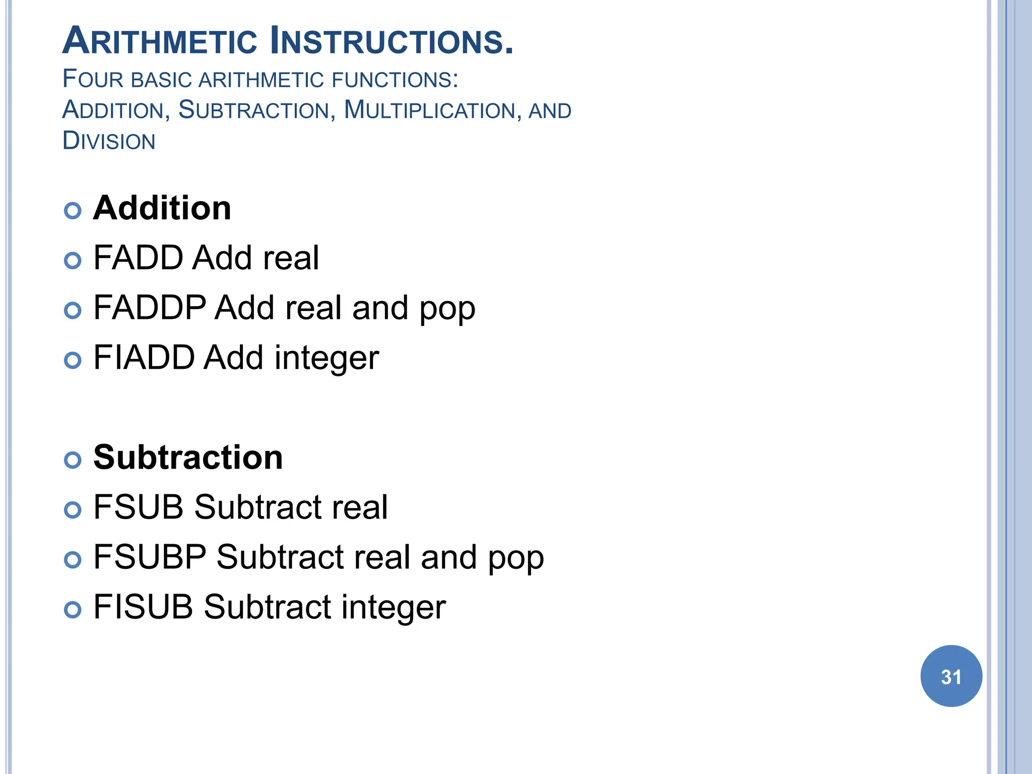
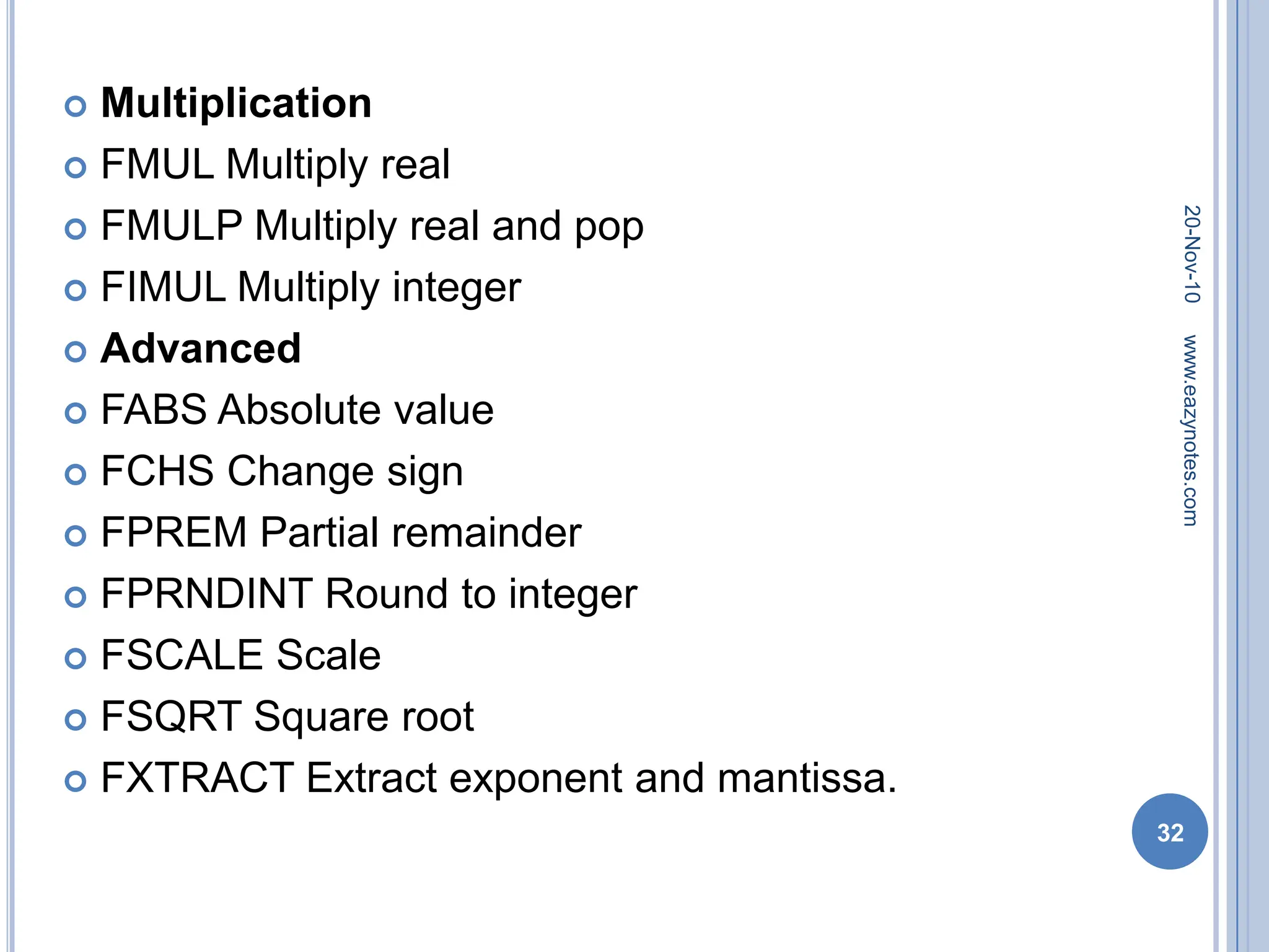
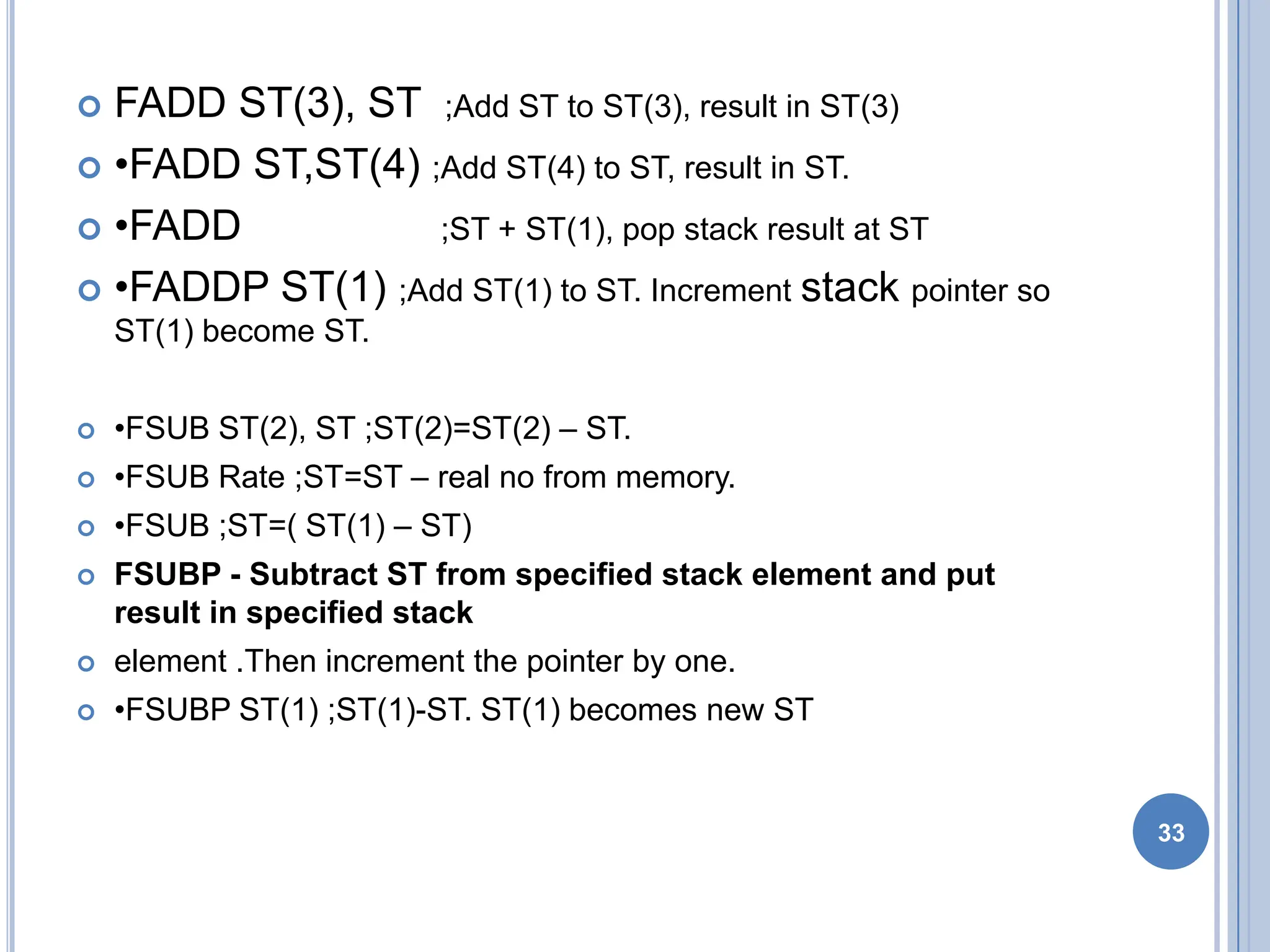
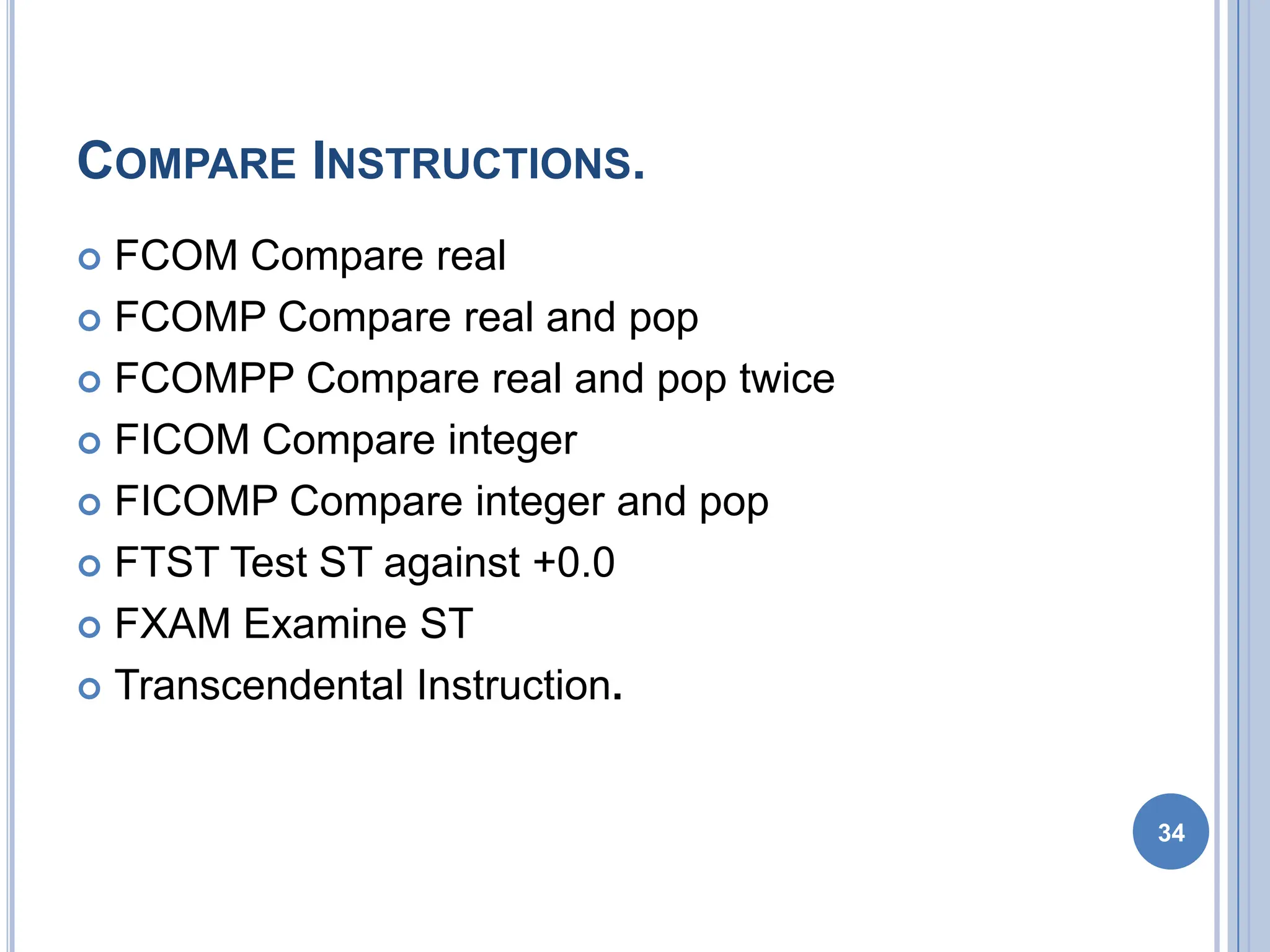
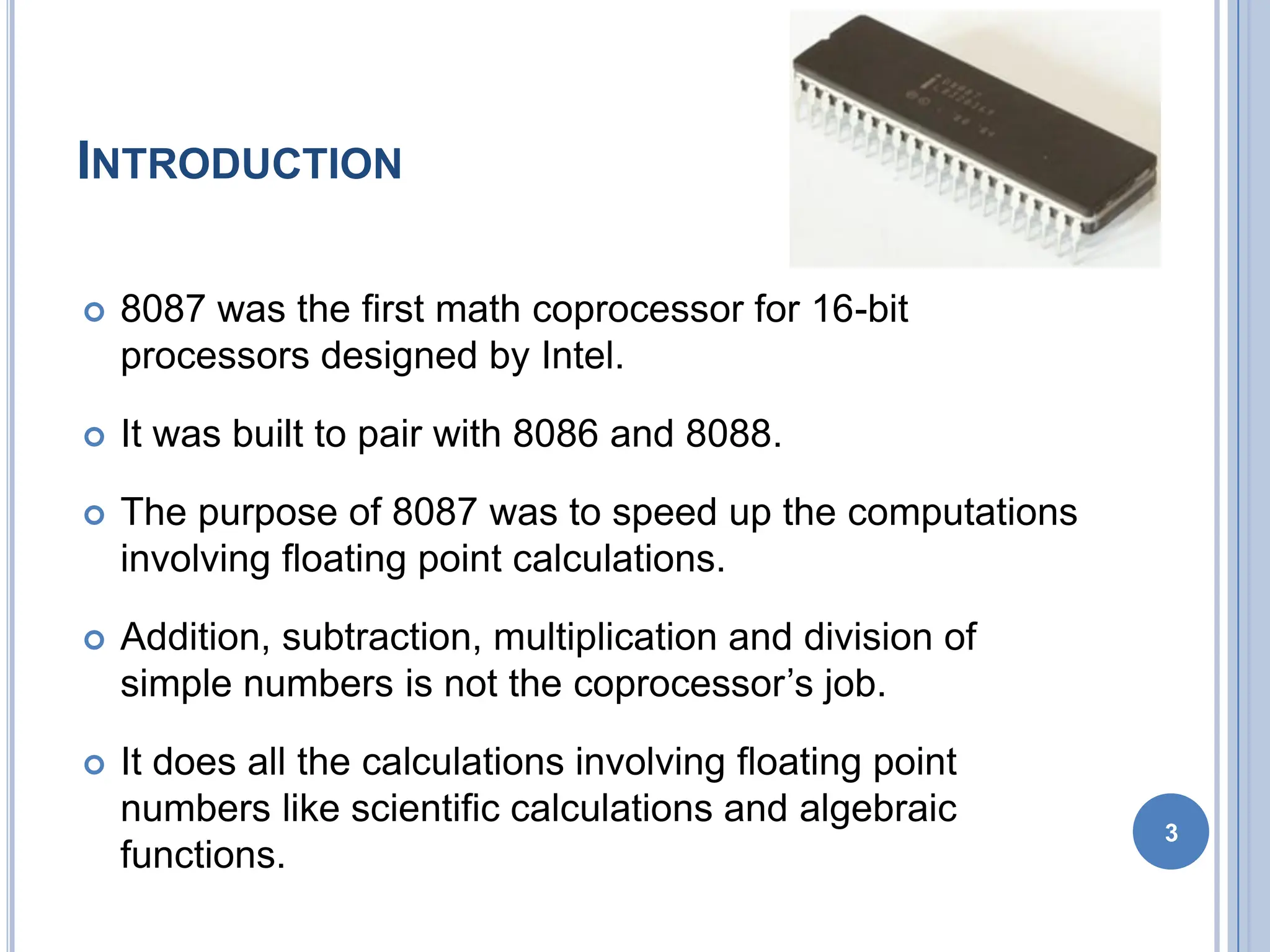
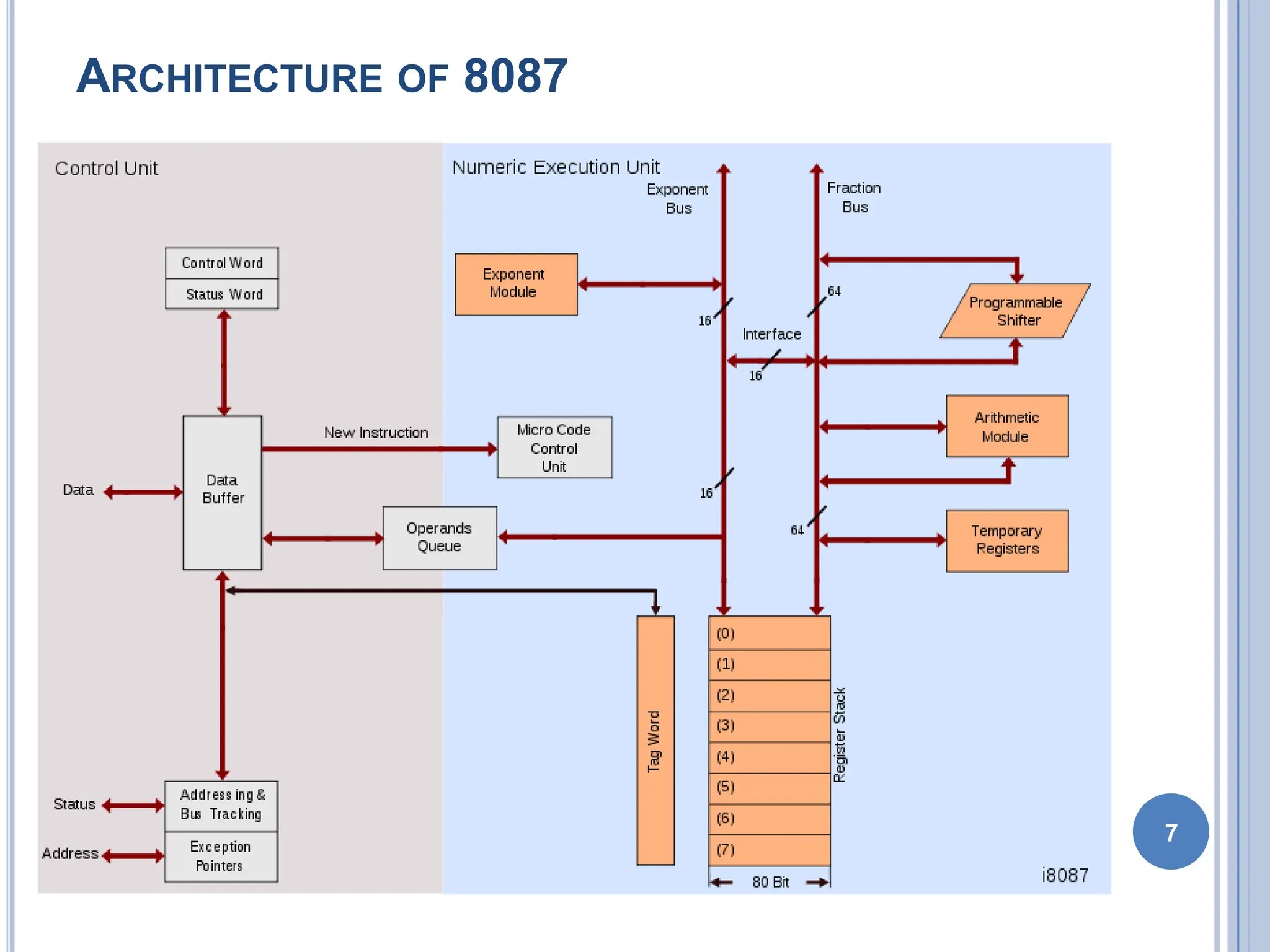
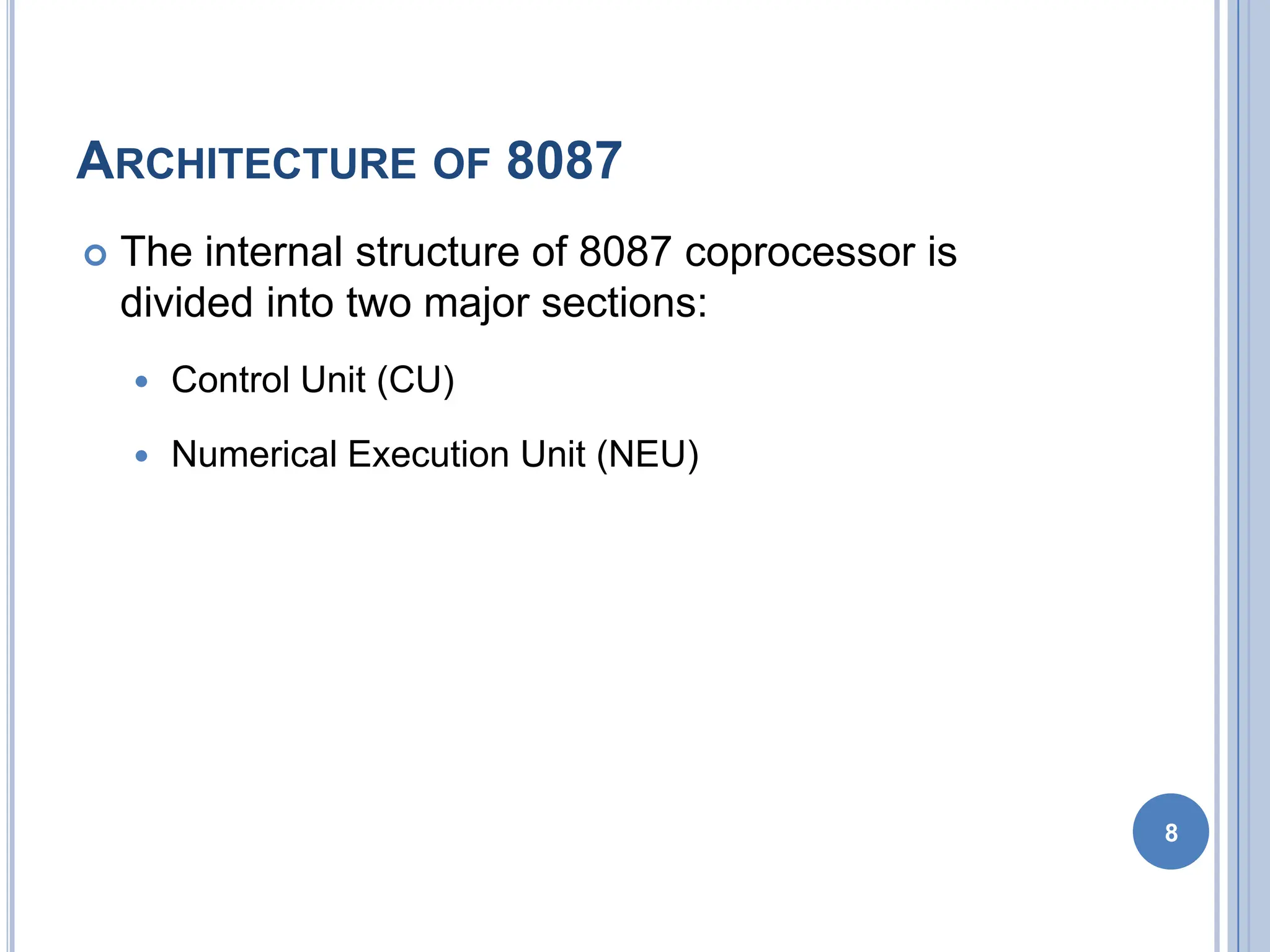
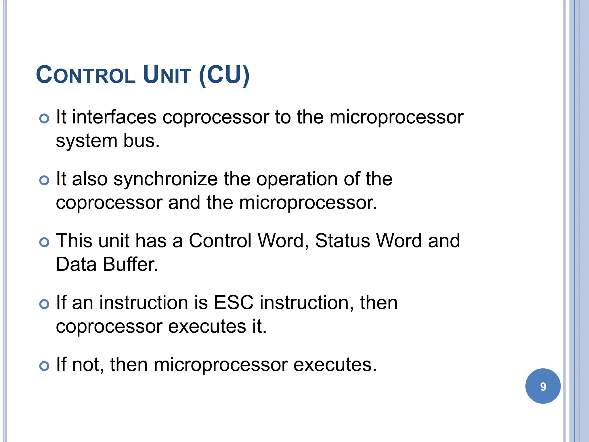
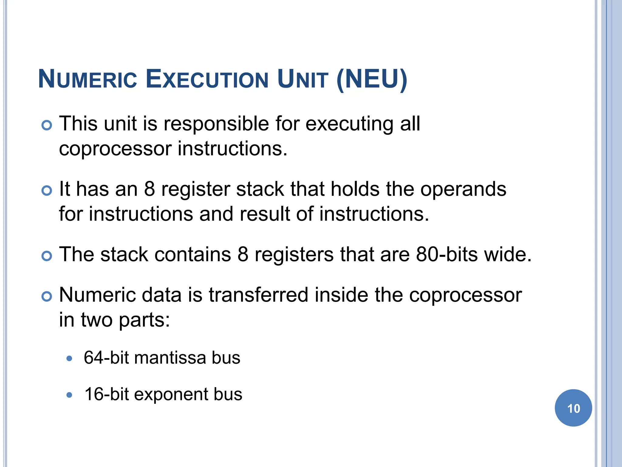
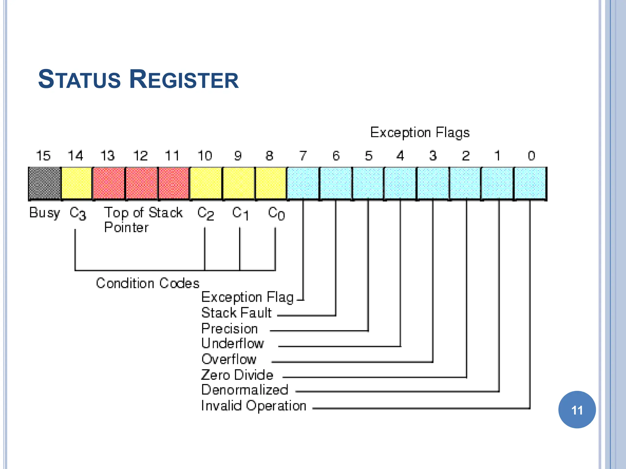
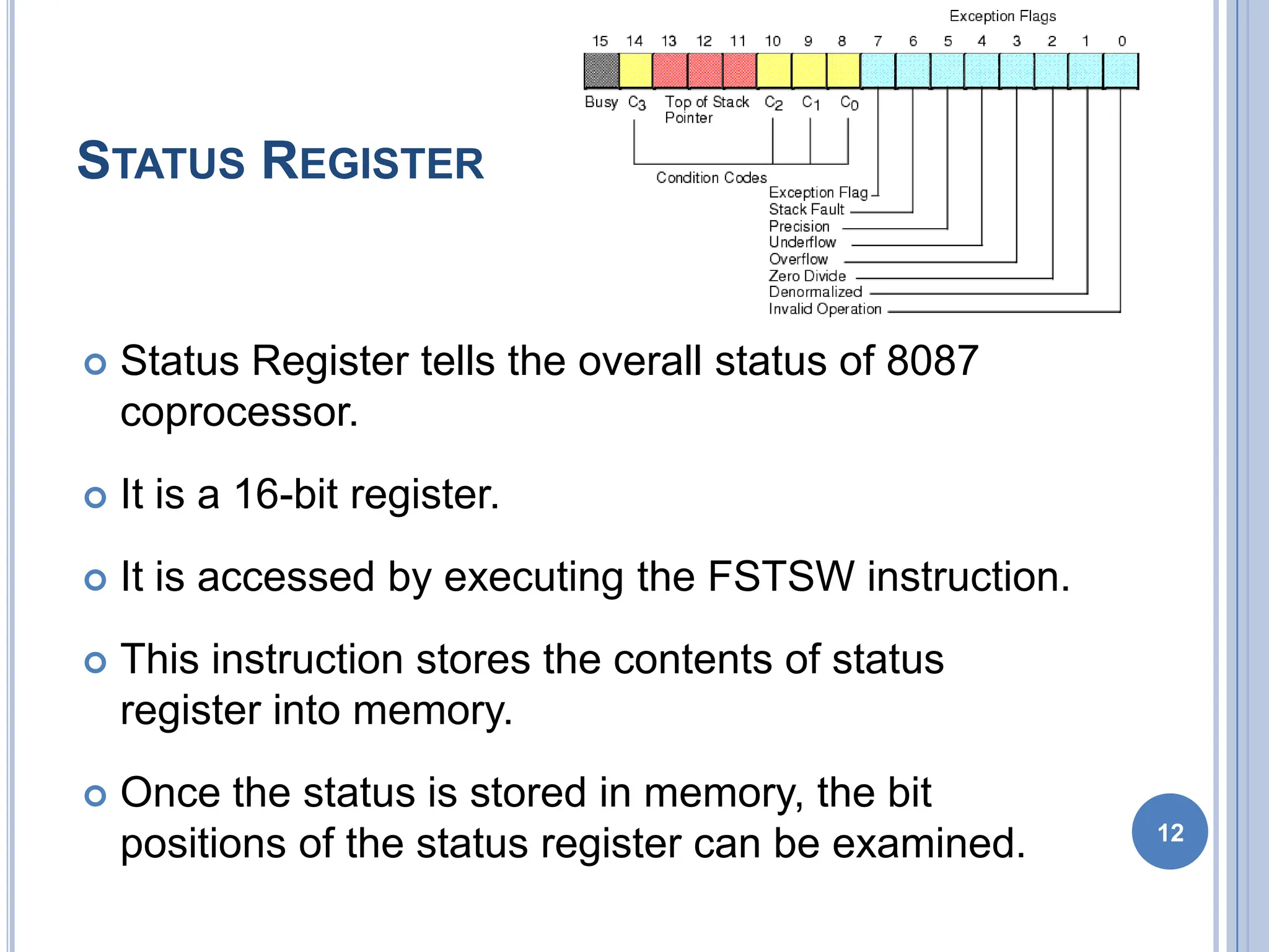
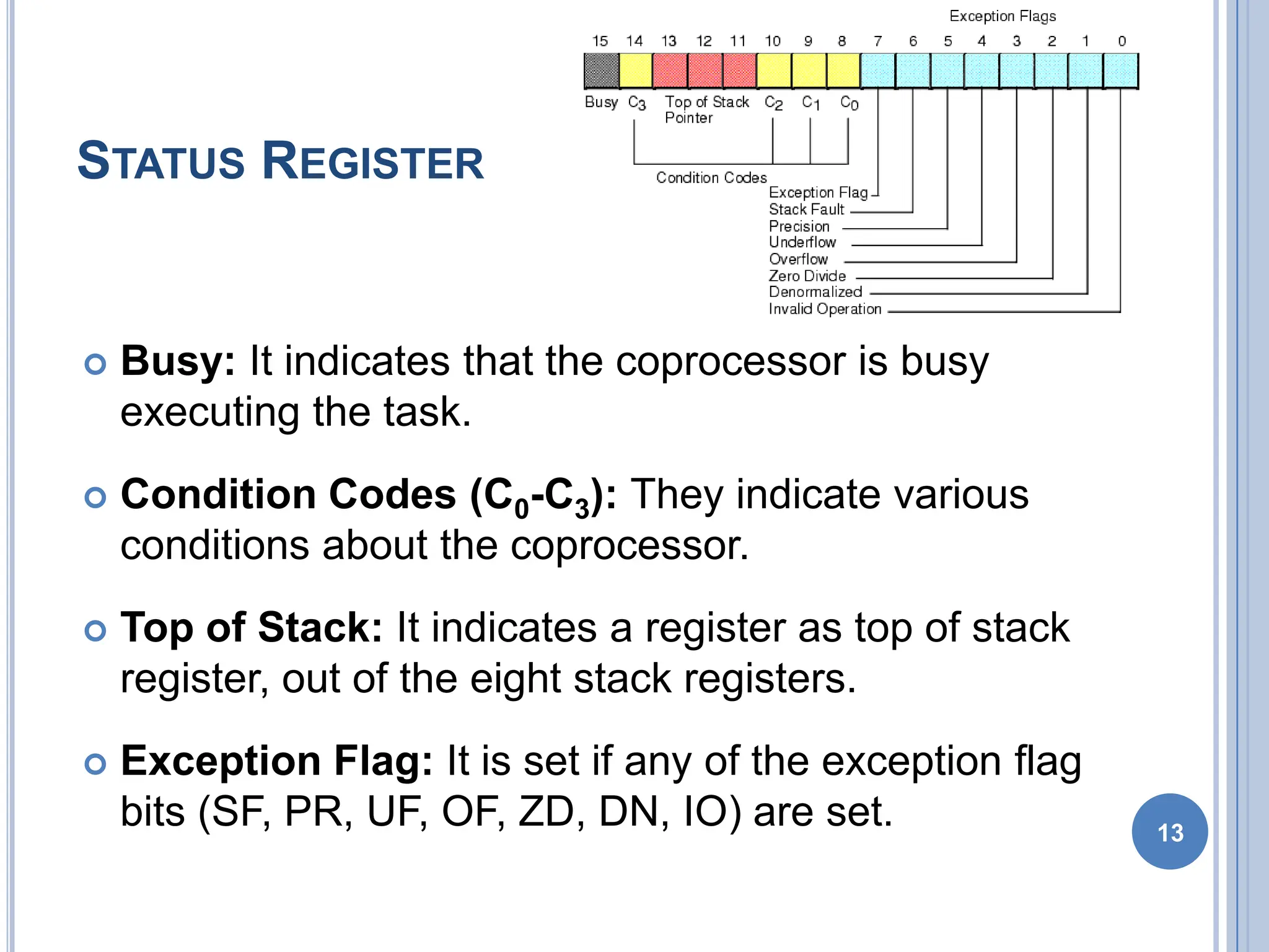
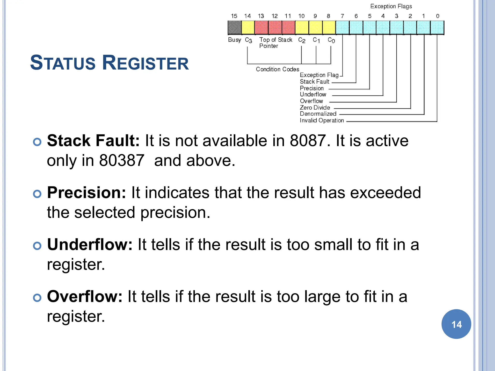
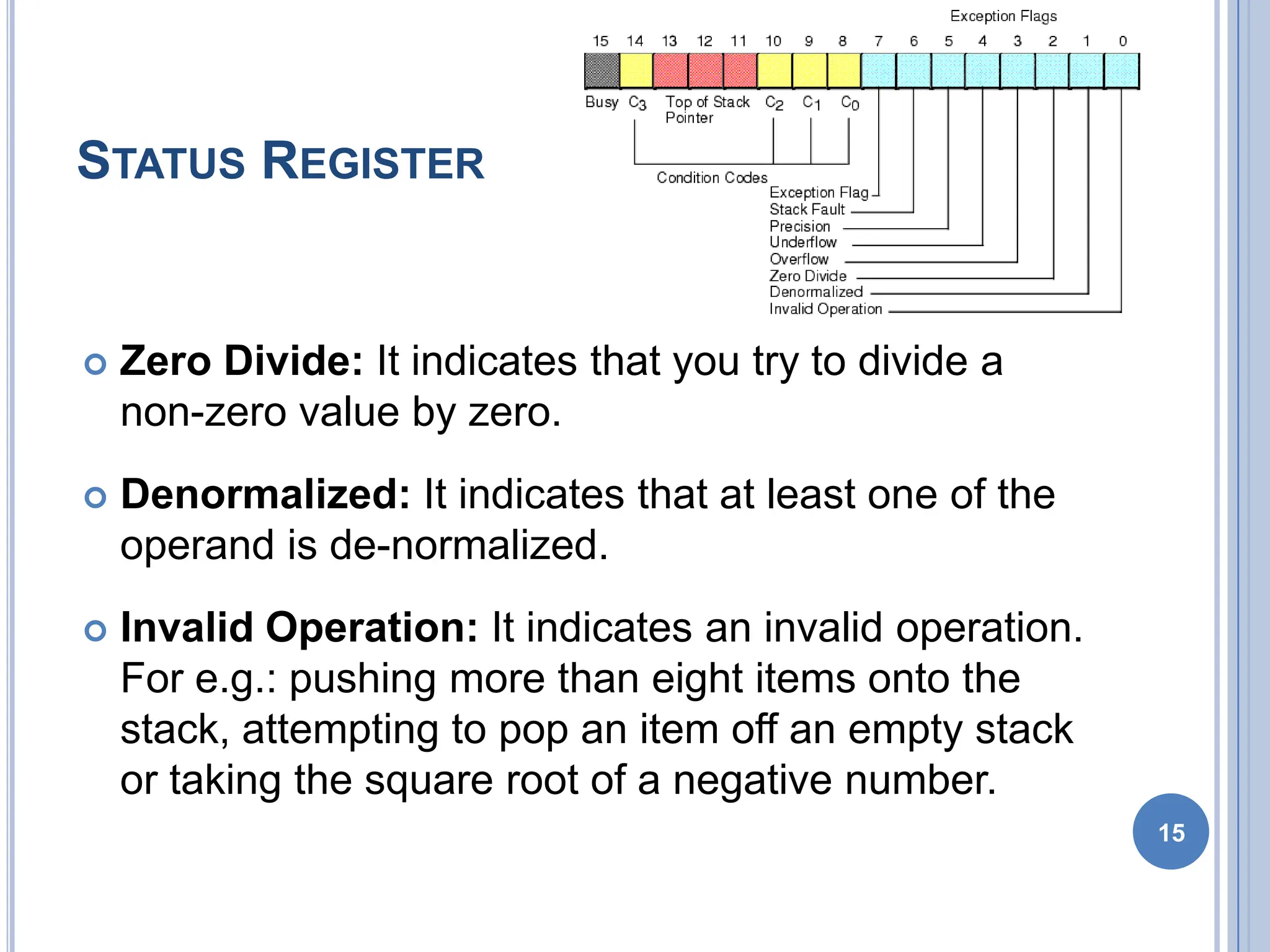
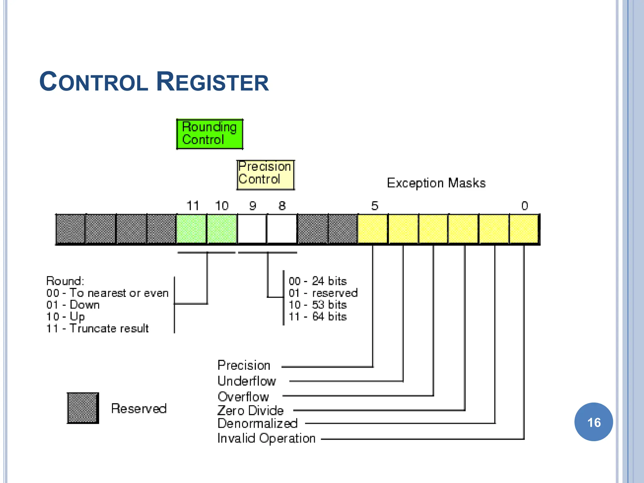
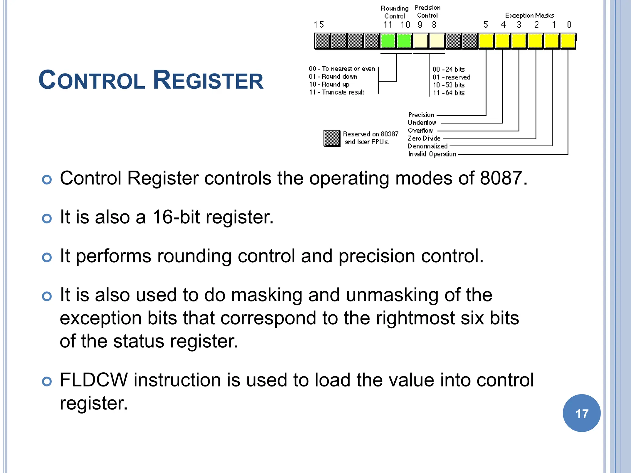
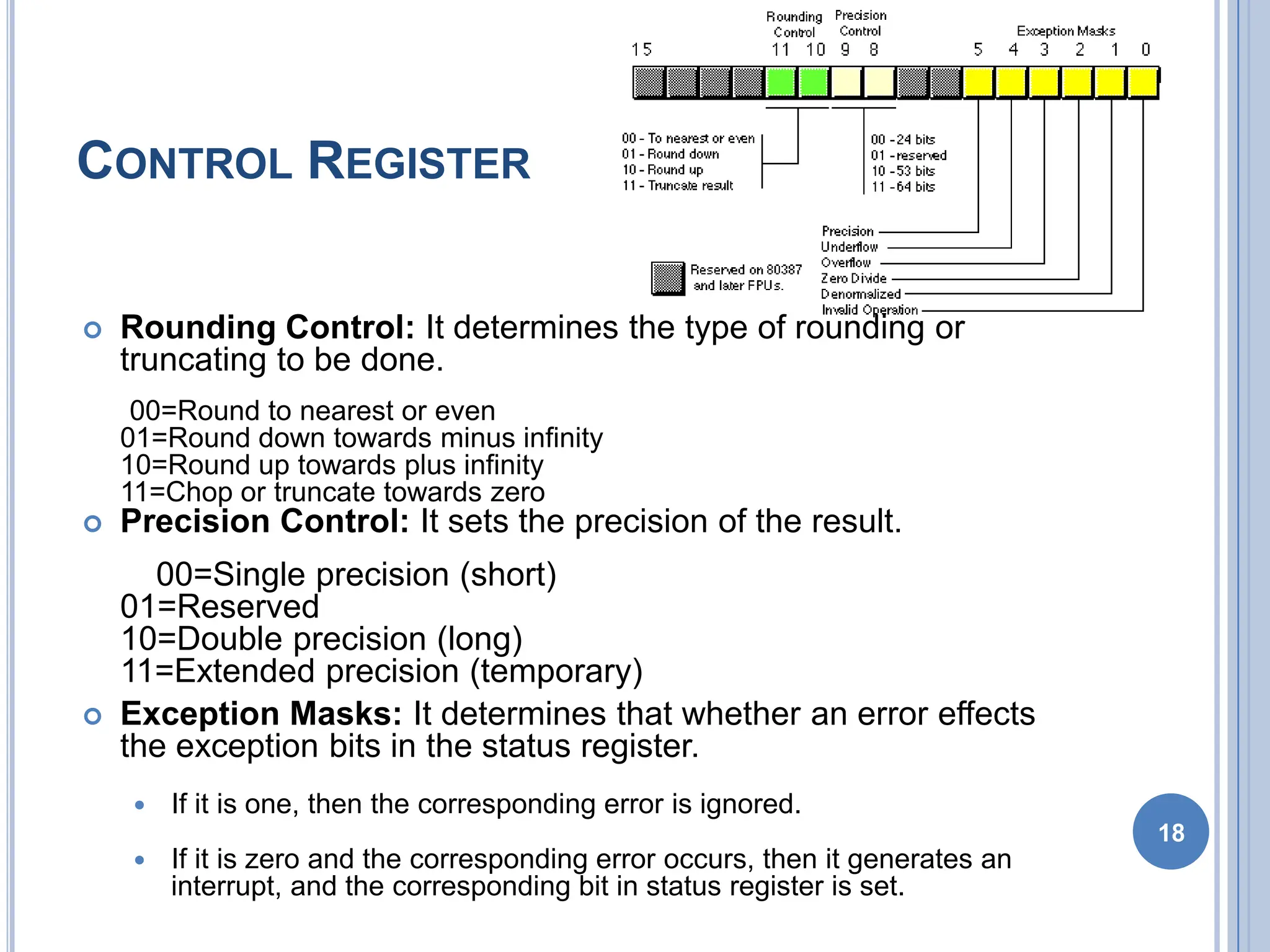
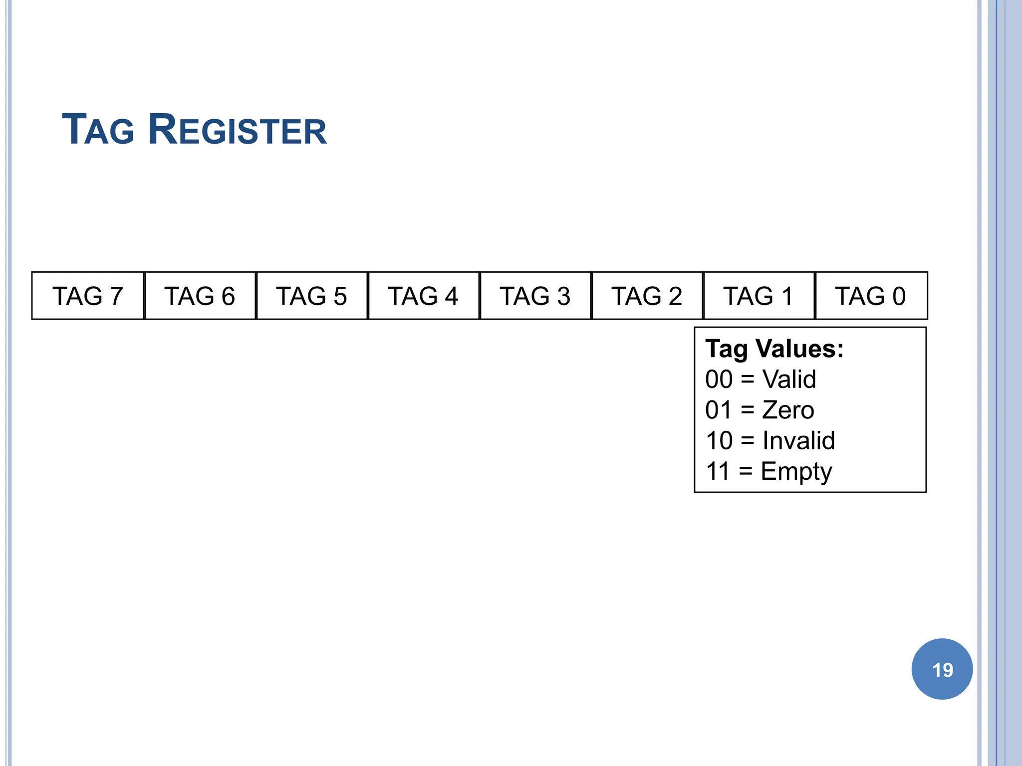
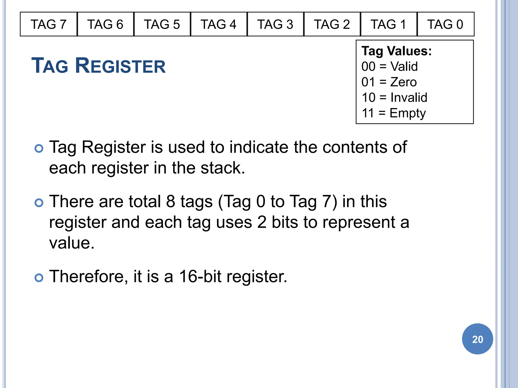
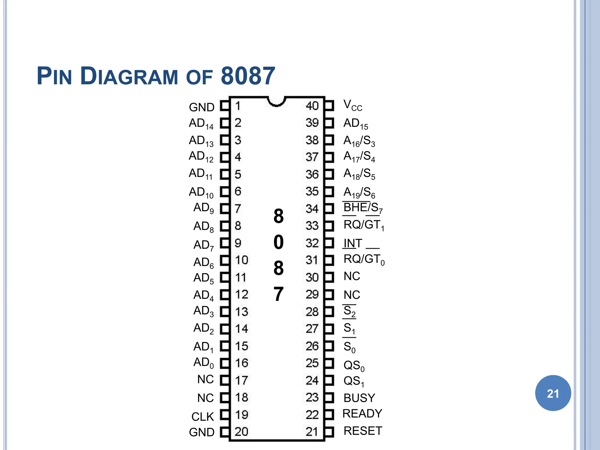
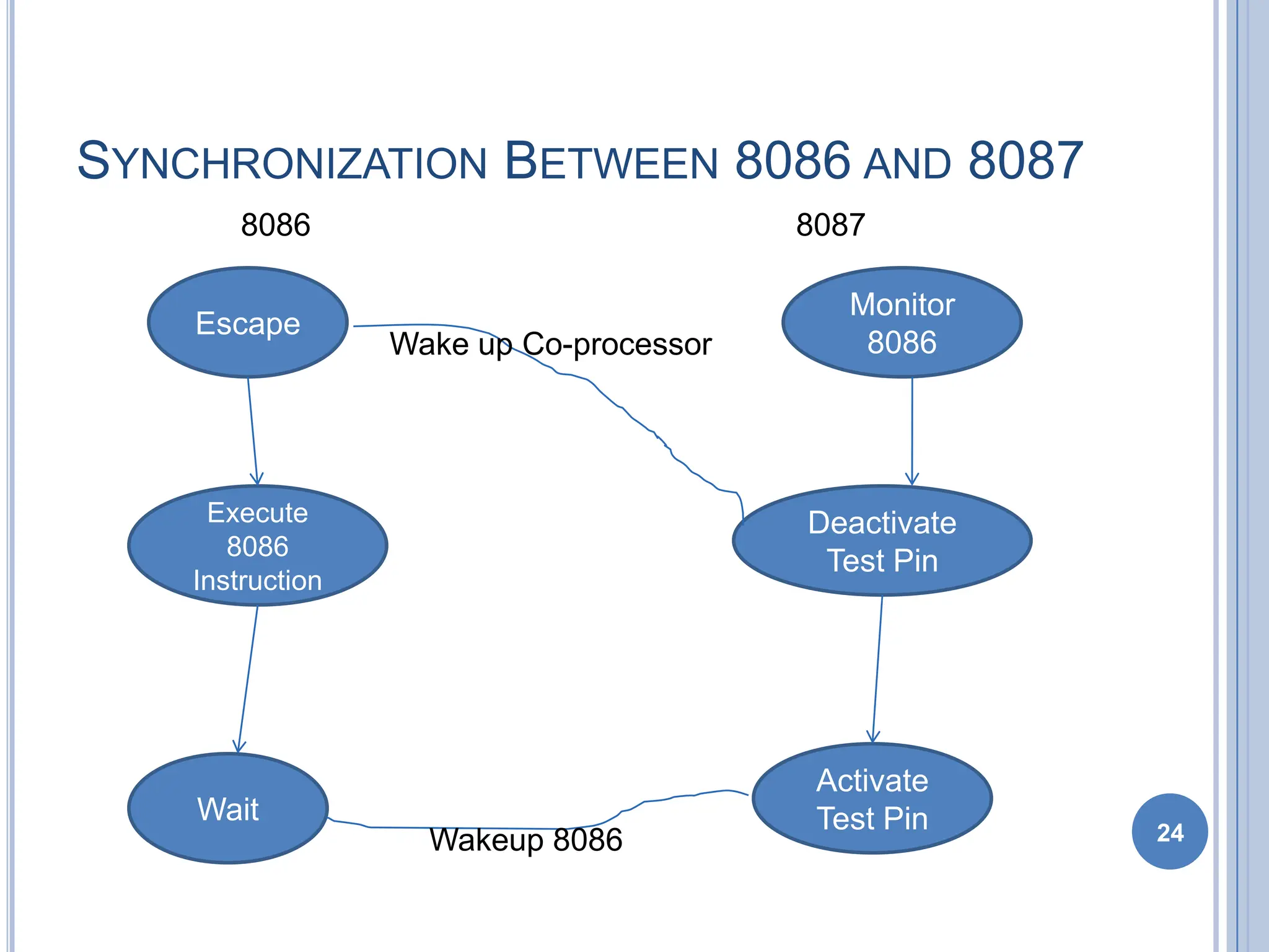
2
Compatible Processor and Coprocessor
Processors
1. 8086 & 8088
2. 80286
3. 80386DX
4. 80386SX
5. 80486DX
6. 80486SX
Coprocessors
1. 8087
2. 80287,80287XL
3. 80287,80387DX
4. 80387SX
5. It is Inbuilt
6. 80487SX
INTRODUCTION
 8087 was the first math coprocessor for 16-bit
processors designed by Intel.
 It was built to pair with 8086 and 8088.
 The purpose of 8087 was to speed up the computations
involving floating point calculations.
 Addition, subtraction, multiplication and division of
simple numbers is not the coprocessor’s job.
 It does all the calculations involving floating point
numbers like scientific calculations and algebraic
functions.
3
INTRODUCTION
 By having a coprocessor, which performs all the calculations,
it can free up a lot of CPU’s time.
 This would allow the CPU to focus all of its resources on the
other functions it has to perform.
 This increases the overall speed and performance of the
entire system.
 This coprocessor introduced about 60 new instructions
available to the programmer.
 All the mnemonics begin with “F” to differentiate them from
the standard 8086 instructions.
 For e.g.: in contrast to ADD/MUL, 8087 provide FADD/FMUL.
4
INTRODUCTION
 Math coprocessor is also called as:
 Numeric Processor Extension (NPX)
 Numeric Data Processor (NDP)
 Floating Point Unit (FPU)
5
ARCHITECTURE OF 8087
 8087 coprocessor is designed to operate with 8086
microprocessor.
 The microprocessor and coprocessor can execute
their respective instructions simultaneously.
 Microprocessor interprets and executes the normal
instruction set and the coprocessor interprets and
executes only the coprocessor instructions.
 All the coprocessor instructions are ESC
instructions, i.e. they start with “F”.
6
ARCHITECTURE OF 8087
7
ARCHITECTURE OF 8087
 The internal structure of 8087 coprocessor is
divided into two major sections:
 Control Unit (CU)
 Numerical Execution Unit (NEU)
8
CONTROL UNIT (CU)
 It interfaces coprocessor to the microprocessor
system bus.
 It also synchronize the operation of the
coprocessor and the microprocessor.
 This unit has a Control Word, Status Word and
Data Buffer.
 If an instruction is ESC instruction, then
coprocessor executes it.
 If not, then microprocessor executes.
9
NUMERIC EXECUTION UNIT (NEU)
 This unit is responsible for executing all
coprocessor instructions.
 It has an 8 register stack that holds the operands
for instructions and result of instructions.
 The stack contains 8 registers that are 80-bits wide.
 Numeric data is transferred inside the coprocessor
in two parts:
 64-bit mantissa bus
 16-bit exponent bus
10
STATUS REGISTER
11
STATUS REGISTER
 Status Register tells the overall status of 8087
coprocessor.
 It is a 16-bit register.
 It is accessed by executing the FSTSW instruction.
 This instruction stores the contents of status
register into memory.
 Once the status is stored in memory, the bit
positions of the status register can be examined. 12
STATUS REGISTER
 Busy: It indicates that the coprocessor is busy
executing the task.
 Condition Codes (C0-C3): They indicate various
conditions about the coprocessor.
 Top of Stack: It indicates a register as top of stack
register, out of the eight stack registers.
 Exception Flag: It is set if any of the exception flag
bits (SF, PR, UF, OF, ZD, DN, IO) are set. 13
STATUS REGISTER
 Stack Fault: It is not available in 8087. It is active
only in 80387 and above.
 Precision: It indicates that the result has exceeded
the selected precision.
 Underflow: It tells if the result is too small to fit in a
register.
 Overflow: It tells if the result is too large to fit in a
register. 14
STATUS REGISTER
 Zero Divide: It indicates that you try to divide a
non-zero value by zero.
 Denormalized: It indicates that at least one of the
operand is de-normalized.
 Invalid Operation: It indicates an invalid operation.
For e.g.: pushing more than eight items onto the
stack, attempting to pop an item off an empty stack
or taking the square root of a negative number.
15
CONTROL REGISTER
16
CONTROL REGISTER
 Control Register controls the operating modes of 8087.
 It is also a 16-bit register.
 It performs rounding control and precision control.
 It is also used to do masking and unmasking of the
exception bits that correspond to the rightmost six bits
of the status register.
 FLDCW instruction is used to load the value into control
register. 17
CONTROL REGISTER
 Rounding Control: It determines the type of rounding or
truncating to be done.
00=Round to nearest or even
01=Round down towards minus infinity
10=Round up towards plus infinity
11=Chop or truncate towards zero
 Precision Control: It sets the precision of the result.
00=Single precision (short)
01=Reserved
10=Double precision (long)
11=Extended precision (temporary)
 Exception Masks: It determines that whether an error effects
the exception bits in the status register.
 If it is one, then the corresponding error is ignored.
 If it is zero and the corresponding error occurs, then it generates an
interrupt, and the corresponding bit in status register is set.
18
TAG REGISTER
19
Tag Values:
00 = Valid
01 = Zero
10 = Invalid
11 = Empty
TAG 7 TAG 6 TAG 5 TAG 4 TAG 3 TAG 2 TAG 1 TAG 0
TAG REGISTER
 Tag Register is used to indicate the contents of
each register in the stack.
 There are total 8 tags (Tag 0 to Tag 7) in this
register and each tag uses 2 bits to represent a
value.
 Therefore, it is a 16-bit register.
20
Tag Values:
00 = Valid
01 = Zero
10 = Invalid
11 = Empty
TAG 7 TAG 6 TAG 5 TAG 4 TAG 3 TAG 2 TAG 1 TAG 0
PIN DIAGRAM OF 8087
21
8
0
8
7
GND
GND
CLK
NC
NC
AD0
AD1
AD2
AD3
AD4
AD5
AD6
AD7
AD8
AD9
AD10
AD11
AD12
AD13
AD14
VCC
AD15
A16/S3
A17/S4
A18/S5
A19/S6
BHE/S7
RQ/GT1
INT
RQ/GT0
NC
NC
S2
S1
S0
QS0
QS1
BUSY
READY
RESET
INTERFACING OF 8086 AND 8087
 Multiplexed address-data bus lines are connected
directly from 8086 to 8087.
 The status lines and the queue status lines are
connected directly from 8086 to 8087.
 The Request/Grant (RQ/GT0 and RQ/GT1) signals
of 8087 are connected to RQ/GT0 and RQ/GT1 of
8086.
 BUSY signal of 8087 is connected to TEST pin of
8086.
22
EXCEPTION HANDLING
 The 8087 detects six different types of exception
conditions that occur during instruction execution.
These will cause an interrupt if unmasked and
interrupts are enabled.
 1) INVALID OPERATION
 2) OVERFLOW
 3) ZERO DIVISOR
 4) UNDERFLOW
 5) DENORMALIZED OPERAND
 6) INEXACT RESULT
23
SYNCHRONIZATION BETWEEN 8086 AND 8087
24
Escape
Activate
Test Pin
Execute
8086
Instruction
Wait
Deactivate
Test Pin
Monitor
8086
Wake up Co-processor
Wakeup 8086
8086 8087
DATA TYPES
 Internally, all data operands are converted to the
80-bit temporary real format.
 We have 3 types.
 •Integer data type
 •Packed BCD data type
 •Real data type
25
INSTRUCTION SET
 The 8087 instruction mnemonics begins with the
letter F which stands for Floating
 point and distinguishes from 8086.
 The 8087 detects an error condition usually called
an exception when it executing an
 instruction it will set the bit in its Status register.
 Types
 I. DATA TRANSFER INSTRUCTIONS.
 II. ARITHMETIC INSTRUCTIONS.
 III. COMPARE INSTRUCTIONS.
20-Nov-10
26
www.eazynotes.com
DATA TRANSFERS INSTRUCTIONS
 REAL TRANSFER
 FLD Load real
 FST Store real
 FSTP Store real and pop
 FXCH Exchange registers
 INTEGER TRANSFER
 FILD Load integer
 FIST Store integer
 FISTP Store integer and pop 27
 FLD Source- Decrements the stack pointer by
one and copies a real number from a
 stack element or memory location to the new ST.
 •FLD ST(3) ;Copies ST(3) to ST.
 •FLD LONG_REAL[BX] ;Number from memory
copied to ST.
 FLD Destination- Copies ST to a specified stack
position or to a specified memory location .
 •FST ST(2) ;Copies ST to ST(2),and increment
stack pointer.
 •FST SHORT_REAL[BX] ;Copy ST to a memory at
a SHORT_REAL[BX]
28
 􀂾 FXCH Destination – Exchange the contents
of ST with the contents of a specified
 stack element.
 •FXCH ST(5) ;Swap ST and ST(5)
20-Nov-10
29
www.eazynotes.com
 FILD Source – Integer load. Convert integer
number from memory to temporary-real
sformat and push on 8087 stack.
 •FILD DWORD PTR[BX] ;Short integer from
memory at [BX].
 FIST Destination- Integer store. Convert number
from ST to integer and copy to memory.
 •FIST LONG_INT ;ST to memory locations named
LONG_INT.
20-Nov-10
30
www.eazynotes.com
ARITHMETIC INSTRUCTIONS.
FOUR BASIC ARITHMETIC FUNCTIONS:
ADDITION, SUBTRACTION, MULTIPLICATION, AND
DIVISION
 Addition
 FADD Add real
 FADDP Add real and pop
 FIADD Add integer
 Subtraction
 FSUB Subtract real
 FSUBP Subtract real and pop
 FISUB Subtract integer
31
 Multiplication
 FMUL Multiply real
 FMULP Multiply real and pop
 FIMUL Multiply integer
 Advanced
 FABS Absolute value
 FCHS Change sign
 FPREM Partial remainder
 FPRNDINT Round to integer
 FSCALE Scale
 FSQRT Square root
 FXTRACT Extract exponent and mantissa.
20-Nov-10
32
www.eazynotes.com
 FADD ST(3), ST ;Add ST to ST(3), result in ST(3)
 •FADD ST,ST(4) ;Add ST(4) to ST, result in ST.
 •FADD ;ST + ST(1), pop stack result at ST
 •FADDP ST(1) ;Add ST(1) to ST. Increment stack pointer so
ST(1) become ST.
 •FSUB ST(2), ST ;ST(2)=ST(2) – ST.
 •FSUB Rate ;ST=ST – real no from memory.
 •FSUB ;ST=( ST(1) – ST)
 FSUBP - Subtract ST from specified stack element and put
result in specified stack
 element .Then increment the pointer by one.
 •FSUBP ST(1) ;ST(1)-ST. ST(1) becomes new ST
33
COMPARE INSTRUCTIONS.
 FCOM Compare real
 FCOMP Compare real and pop
 FCOMPP Compare real and pop twice
 FICOM Compare integer
 FICOMP Compare integer and pop
 FTST Test ST against +0.0
 FXAM Examine ST
 Transcendental Instruction.
34

8087 MICROPROCESSOR and diagram with definition.pdf

  • 1.
    2 Compatible Processor andCoprocessor Processors 1. 8086 & 8088 2. 80286 3. 80386DX 4. 80386SX 5. 80486DX 6. 80486SX Coprocessors 1. 8087 2. 80287,80287XL 3. 80287,80387DX 4. 80387SX 5. It is Inbuilt 6. 80487SX
  • 2.
    INTRODUCTION  8087 wasthe first math coprocessor for 16-bit processors designed by Intel.  It was built to pair with 8086 and 8088.  The purpose of 8087 was to speed up the computations involving floating point calculations.  Addition, subtraction, multiplication and division of simple numbers is not the coprocessor’s job.  It does all the calculations involving floating point numbers like scientific calculations and algebraic functions. 3
  • 3.
    INTRODUCTION  By havinga coprocessor, which performs all the calculations, it can free up a lot of CPU’s time.  This would allow the CPU to focus all of its resources on the other functions it has to perform.  This increases the overall speed and performance of the entire system.  This coprocessor introduced about 60 new instructions available to the programmer.  All the mnemonics begin with “F” to differentiate them from the standard 8086 instructions.  For e.g.: in contrast to ADD/MUL, 8087 provide FADD/FMUL. 4
  • 4.
    INTRODUCTION  Math coprocessoris also called as:  Numeric Processor Extension (NPX)  Numeric Data Processor (NDP)  Floating Point Unit (FPU) 5
  • 5.
    ARCHITECTURE OF 8087 8087 coprocessor is designed to operate with 8086 microprocessor.  The microprocessor and coprocessor can execute their respective instructions simultaneously.  Microprocessor interprets and executes the normal instruction set and the coprocessor interprets and executes only the coprocessor instructions.  All the coprocessor instructions are ESC instructions, i.e. they start with “F”. 6
  • 6.
  • 7.
    ARCHITECTURE OF 8087 The internal structure of 8087 coprocessor is divided into two major sections:  Control Unit (CU)  Numerical Execution Unit (NEU) 8
  • 8.
    CONTROL UNIT (CU) It interfaces coprocessor to the microprocessor system bus.  It also synchronize the operation of the coprocessor and the microprocessor.  This unit has a Control Word, Status Word and Data Buffer.  If an instruction is ESC instruction, then coprocessor executes it.  If not, then microprocessor executes. 9
  • 9.
    NUMERIC EXECUTION UNIT(NEU)  This unit is responsible for executing all coprocessor instructions.  It has an 8 register stack that holds the operands for instructions and result of instructions.  The stack contains 8 registers that are 80-bits wide.  Numeric data is transferred inside the coprocessor in two parts:  64-bit mantissa bus  16-bit exponent bus 10
  • 10.
  • 11.
    STATUS REGISTER  StatusRegister tells the overall status of 8087 coprocessor.  It is a 16-bit register.  It is accessed by executing the FSTSW instruction.  This instruction stores the contents of status register into memory.  Once the status is stored in memory, the bit positions of the status register can be examined. 12
  • 12.
    STATUS REGISTER  Busy:It indicates that the coprocessor is busy executing the task.  Condition Codes (C0-C3): They indicate various conditions about the coprocessor.  Top of Stack: It indicates a register as top of stack register, out of the eight stack registers.  Exception Flag: It is set if any of the exception flag bits (SF, PR, UF, OF, ZD, DN, IO) are set. 13
  • 13.
    STATUS REGISTER  StackFault: It is not available in 8087. It is active only in 80387 and above.  Precision: It indicates that the result has exceeded the selected precision.  Underflow: It tells if the result is too small to fit in a register.  Overflow: It tells if the result is too large to fit in a register. 14
  • 14.
    STATUS REGISTER  ZeroDivide: It indicates that you try to divide a non-zero value by zero.  Denormalized: It indicates that at least one of the operand is de-normalized.  Invalid Operation: It indicates an invalid operation. For e.g.: pushing more than eight items onto the stack, attempting to pop an item off an empty stack or taking the square root of a negative number. 15
  • 15.
  • 16.
    CONTROL REGISTER  ControlRegister controls the operating modes of 8087.  It is also a 16-bit register.  It performs rounding control and precision control.  It is also used to do masking and unmasking of the exception bits that correspond to the rightmost six bits of the status register.  FLDCW instruction is used to load the value into control register. 17
  • 17.
    CONTROL REGISTER  RoundingControl: It determines the type of rounding or truncating to be done. 00=Round to nearest or even 01=Round down towards minus infinity 10=Round up towards plus infinity 11=Chop or truncate towards zero  Precision Control: It sets the precision of the result. 00=Single precision (short) 01=Reserved 10=Double precision (long) 11=Extended precision (temporary)  Exception Masks: It determines that whether an error effects the exception bits in the status register.  If it is one, then the corresponding error is ignored.  If it is zero and the corresponding error occurs, then it generates an interrupt, and the corresponding bit in status register is set. 18
  • 18.
    TAG REGISTER 19 Tag Values: 00= Valid 01 = Zero 10 = Invalid 11 = Empty TAG 7 TAG 6 TAG 5 TAG 4 TAG 3 TAG 2 TAG 1 TAG 0
  • 19.
    TAG REGISTER  TagRegister is used to indicate the contents of each register in the stack.  There are total 8 tags (Tag 0 to Tag 7) in this register and each tag uses 2 bits to represent a value.  Therefore, it is a 16-bit register. 20 Tag Values: 00 = Valid 01 = Zero 10 = Invalid 11 = Empty TAG 7 TAG 6 TAG 5 TAG 4 TAG 3 TAG 2 TAG 1 TAG 0
  • 20.
    PIN DIAGRAM OF8087 21 8 0 8 7 GND GND CLK NC NC AD0 AD1 AD2 AD3 AD4 AD5 AD6 AD7 AD8 AD9 AD10 AD11 AD12 AD13 AD14 VCC AD15 A16/S3 A17/S4 A18/S5 A19/S6 BHE/S7 RQ/GT1 INT RQ/GT0 NC NC S2 S1 S0 QS0 QS1 BUSY READY RESET
  • 21.
    INTERFACING OF 8086AND 8087  Multiplexed address-data bus lines are connected directly from 8086 to 8087.  The status lines and the queue status lines are connected directly from 8086 to 8087.  The Request/Grant (RQ/GT0 and RQ/GT1) signals of 8087 are connected to RQ/GT0 and RQ/GT1 of 8086.  BUSY signal of 8087 is connected to TEST pin of 8086. 22
  • 22.
    EXCEPTION HANDLING  The8087 detects six different types of exception conditions that occur during instruction execution. These will cause an interrupt if unmasked and interrupts are enabled.  1) INVALID OPERATION  2) OVERFLOW  3) ZERO DIVISOR  4) UNDERFLOW  5) DENORMALIZED OPERAND  6) INEXACT RESULT 23
  • 23.
    SYNCHRONIZATION BETWEEN 8086AND 8087 24 Escape Activate Test Pin Execute 8086 Instruction Wait Deactivate Test Pin Monitor 8086 Wake up Co-processor Wakeup 8086 8086 8087
  • 24.
    DATA TYPES  Internally,all data operands are converted to the 80-bit temporary real format.  We have 3 types.  •Integer data type  •Packed BCD data type  •Real data type 25
  • 25.
    INSTRUCTION SET  The8087 instruction mnemonics begins with the letter F which stands for Floating  point and distinguishes from 8086.  The 8087 detects an error condition usually called an exception when it executing an  instruction it will set the bit in its Status register.  Types  I. DATA TRANSFER INSTRUCTIONS.  II. ARITHMETIC INSTRUCTIONS.  III. COMPARE INSTRUCTIONS. 20-Nov-10 26 www.eazynotes.com
  • 26.
    DATA TRANSFERS INSTRUCTIONS REAL TRANSFER  FLD Load real  FST Store real  FSTP Store real and pop  FXCH Exchange registers  INTEGER TRANSFER  FILD Load integer  FIST Store integer  FISTP Store integer and pop 27
  • 27.
     FLD Source-Decrements the stack pointer by one and copies a real number from a  stack element or memory location to the new ST.  •FLD ST(3) ;Copies ST(3) to ST.  •FLD LONG_REAL[BX] ;Number from memory copied to ST.  FLD Destination- Copies ST to a specified stack position or to a specified memory location .  •FST ST(2) ;Copies ST to ST(2),and increment stack pointer.  •FST SHORT_REAL[BX] ;Copy ST to a memory at a SHORT_REAL[BX] 28
  • 28.
     􀂾 FXCHDestination – Exchange the contents of ST with the contents of a specified  stack element.  •FXCH ST(5) ;Swap ST and ST(5) 20-Nov-10 29 www.eazynotes.com
  • 29.
     FILD Source– Integer load. Convert integer number from memory to temporary-real sformat and push on 8087 stack.  •FILD DWORD PTR[BX] ;Short integer from memory at [BX].  FIST Destination- Integer store. Convert number from ST to integer and copy to memory.  •FIST LONG_INT ;ST to memory locations named LONG_INT. 20-Nov-10 30 www.eazynotes.com
  • 30.
    ARITHMETIC INSTRUCTIONS. FOUR BASICARITHMETIC FUNCTIONS: ADDITION, SUBTRACTION, MULTIPLICATION, AND DIVISION  Addition  FADD Add real  FADDP Add real and pop  FIADD Add integer  Subtraction  FSUB Subtract real  FSUBP Subtract real and pop  FISUB Subtract integer 31
  • 31.
     Multiplication  FMULMultiply real  FMULP Multiply real and pop  FIMUL Multiply integer  Advanced  FABS Absolute value  FCHS Change sign  FPREM Partial remainder  FPRNDINT Round to integer  FSCALE Scale  FSQRT Square root  FXTRACT Extract exponent and mantissa. 20-Nov-10 32 www.eazynotes.com
  • 32.
     FADD ST(3),ST ;Add ST to ST(3), result in ST(3)  •FADD ST,ST(4) ;Add ST(4) to ST, result in ST.  •FADD ;ST + ST(1), pop stack result at ST  •FADDP ST(1) ;Add ST(1) to ST. Increment stack pointer so ST(1) become ST.  •FSUB ST(2), ST ;ST(2)=ST(2) – ST.  •FSUB Rate ;ST=ST – real no from memory.  •FSUB ;ST=( ST(1) – ST)  FSUBP - Subtract ST from specified stack element and put result in specified stack  element .Then increment the pointer by one.  •FSUBP ST(1) ;ST(1)-ST. ST(1) becomes new ST 33
  • 33.
    COMPARE INSTRUCTIONS.  FCOMCompare real  FCOMP Compare real and pop  FCOMPP Compare real and pop twice  FICOM Compare integer  FICOMP Compare integer and pop  FTST Test ST against +0.0  FXAM Examine ST  Transcendental Instruction. 34