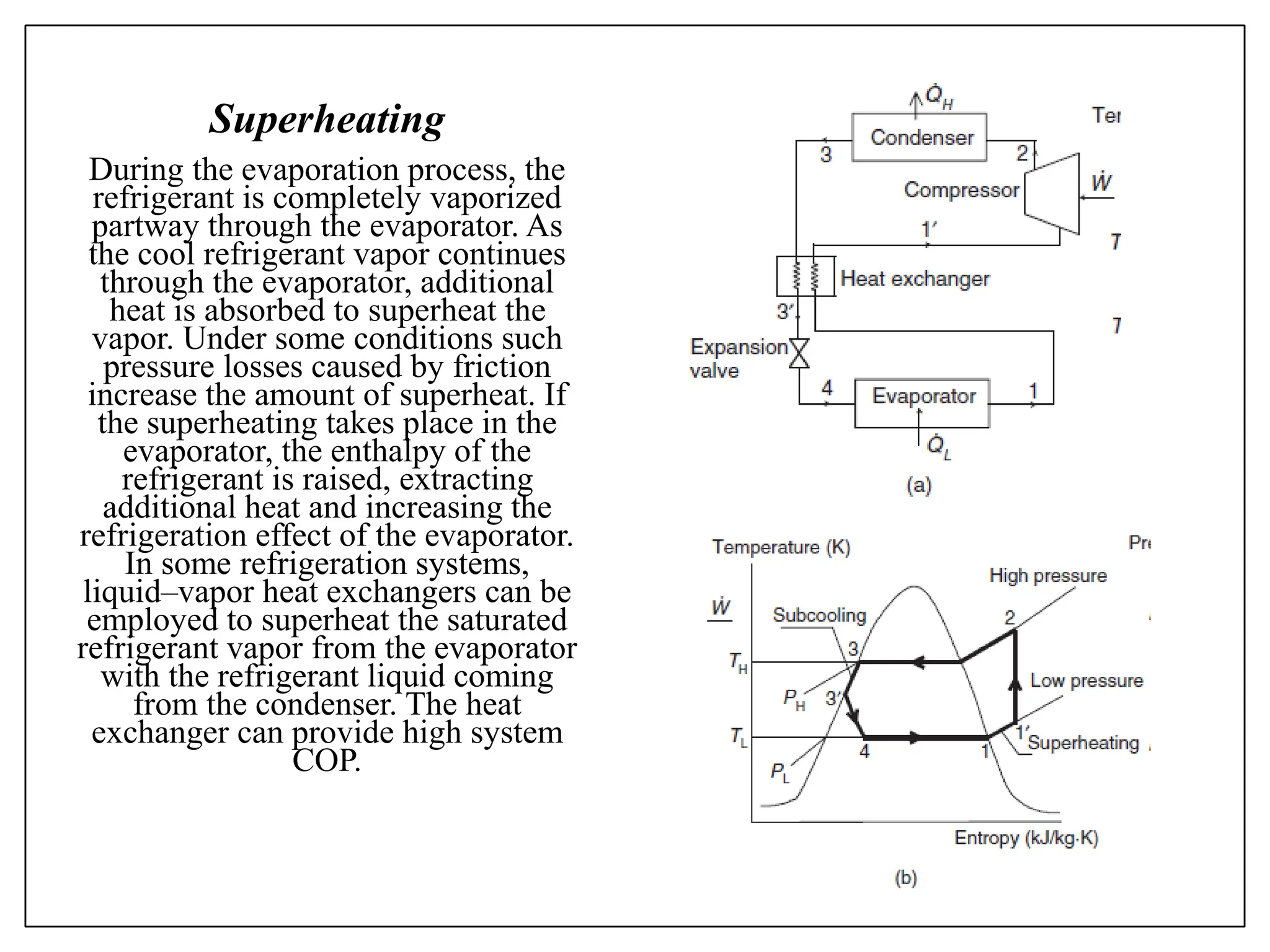
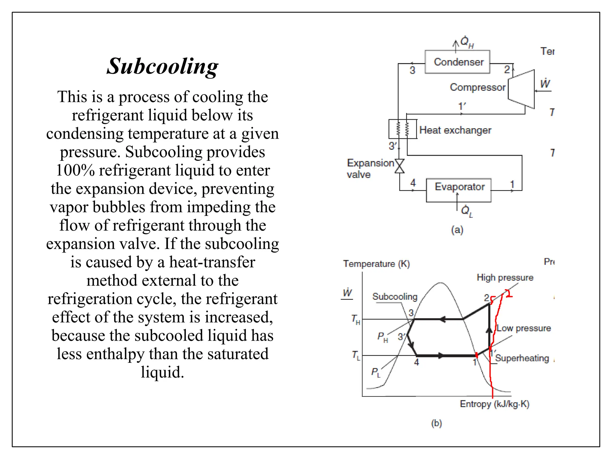
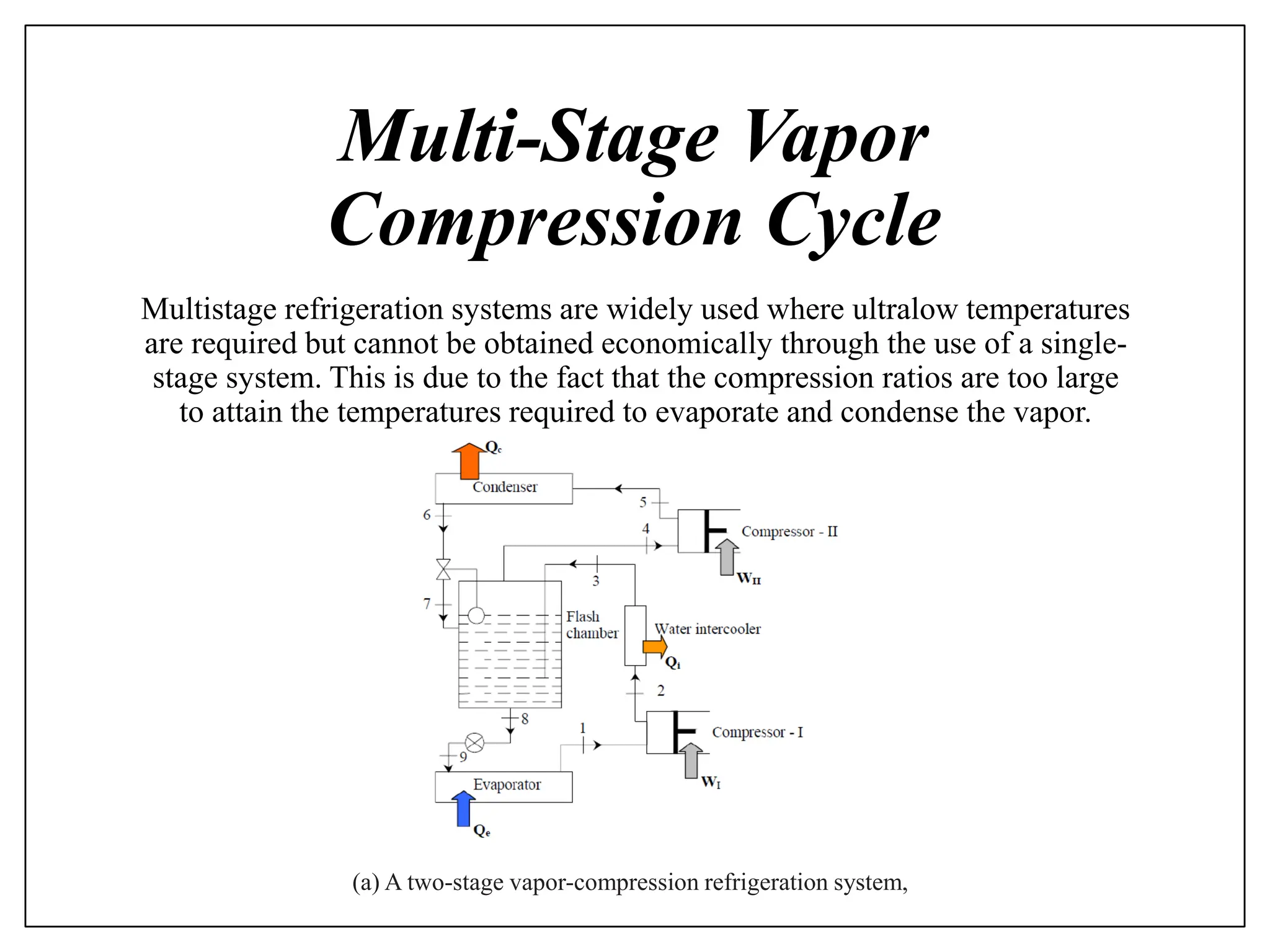
MODULE
4
Actual Stage and Multi-Stage
Vapor Compression Cycle
Intended Learning Outcome
ILO1: Understand the actual vapor compression
refrigeration diagrams (P-H and T-S diagrams as
well) and the function of the basic components.
ILO2: Understand multi-stage vapor compression
cycle diagrams.
ILO3: Able to compute the C.O.P., work, flow
rate, and other operating parameters
ILO4: Compute the effect of evaporating
temperature on the COP of multi-stage cycle.
Actual Vapor Compression
Refrigeration System
There are some clear differences between the practical (actual) cycle and the
theoretical cycle (standard ideal cycle) primarily because of the pressure and
temperature drops associated with refrigerant flow and heat transfer to or from
the surroundings.
An actual vapor-compression refrigeration system and its
T–s diagram.
Superheating and Subcooling
Superheating (referring to superheating of the refrigerant vapor
leaving evaporator) and subcooling (referring to subcooling of
refrigerant liquid leaving the condenser) are apparently two significant
processes in practical vapor-compression refrigeration systems and are
applied to provide better efficiency (COP) and to avoid some technical
problems, as will be explained below.
Superheating
During the evaporation process, the
refrigerant is completely vaporized
partway through the evaporator. As
the cool refrigerant vapor continues
through the evaporator, additional
heat is absorbed to superheat the
vapor. Under some conditions such
pressure losses caused by friction
increase the amount of superheat. If
the superheating takes place in the
evaporator, the enthalpy of the
refrigerant is raised, extracting
additional heat and increasing the
refrigeration effect of the evaporator.
In some refrigeration systems,
liquid–vapor heat exchangers can be
employed to superheat the saturated
refrigerant vapor from the evaporator
with the refrigerant liquid coming
from the condenser. The heat
exchanger can provide high system
COP.
Subcooling
This is a process of cooling the
refrigerant liquid below its
condensing temperature at a given
pressure. Subcooling provides
100% refrigerant liquid to enter
the expansion device, preventing
vapor bubbles from impeding the
flow of refrigerant through the
expansion valve. If the subcooling
is caused by a heat-transfer
method external to the
refrigeration cycle, the refrigerant
effect of the system is increased,
because the subcooled liquid has
less enthalpy than the saturated
liquid.
Exercise 4.1
A vapor-compression refrigeration cycle with refrigerant-134a as the
working fluid operates between pressure limits of 240 and 1600 kPa.
The isentropic efficiency of the compressor is 78%. The refrigerant is
superheated by 5.4 ◦C at the compressor inlet and subcooled by 5.9 ◦C
at the exit of the condenser. Determine (a) the heat absorption in the
evaporator, (b) the heat rejection in the condenser, (c) the work input,
and (d) the COP. (e) Also determine all parameters if the cycle
operated on the ideal vapor-compression refrigeration cycle between
the same pressure limits.
Multi-Stage Vapor
Compression Cycle
Multistage refrigeration systems are widely used where ultralow temperatures
are required but cannot be obtained economically through the use of a single-
stage system. This is due to the fact that the compression ratios are too large
to attain the temperatures required to evaporate and condense the vapor.
(a) A two-stage vapor-compression refrigeration system,
The multistage system uses two or more compressors connected in
series in the same refrigeration system. The refrigerant becomes a
denser vapor while it passes through each compressor.
The performance of single stage systems shows that these are
adequate as long as the temperature difference between evaporator and
condenser (temperature lift) is small.
The temperature lift can become large either due to the requirement of
very low evaporator temperatures and/or due to the requirement of
very high condensing temperatures.
For example, in frozen food industries the required evaporator can be
as low as –40oC, while in chemical industries temperatures as low
as–150oC may be required for liquefaction of gases.
On the condenser side, Refrigeration system is used as a heat pump
for heating applications such as process heating, drying etc.
Multi-stage systems are also used in applications requiring
refrigeration at different temperatures. For example, in a dairy plant
refrigeration may be required at 30oC for making ice cream and at 2oC
for chilling milk. In such cases it may be advantageous to use a multi
evaporator system
Multi-Stage Vapor Compression Cycle
with a flash tank for intercooling only
Intercooling using liquid refrigerant from
condenser in the flash tank may or may not
reduce the power input to the system, as it
depends upon the nature of the refrigerant.
The heat rejected by the refrigerant during
intercooling generates additional vapour in
the flash tank, which has to be compressed
by the high stage compressor.
Thus, the mass flow rate of refrigerant
through the high stage compressor will be
more than that of the low stage compressor.
A flash chamber is a device which separates
liquid from vapors. Only liquid is then
passed to evaporator and the vapors will be
passed to the compressor directly. This flash
chamber is known as flash intercooling.
Energy Analysis
Multi-Stage Vapor Compression Cycle
with a flash tank for intercooling only
𝑄𝐻 = 𝑚2 + 𝑚6 ℎ4 − ℎ5
𝑄𝐿 = 𝑚2 ℎ1 − ℎ7
𝑊𝑐1 = 𝑚2 ℎ2 − ℎ1
𝑊𝑐2 = 𝑚2 + 𝑚6 ℎ4 − ℎ3
𝑊𝑛𝑒𝑡= 𝑊𝑐1 + 𝑊𝑐2
𝐶𝑂𝑃 =
𝑄𝐿
𝑊𝑛𝑒𝑡
𝑃𝑖 = 𝑃6 = 𝑃3 = 𝑃2 = 𝑃𝐻 × 𝑃𝐿
𝑄𝐿
𝑄𝐻
𝑃𝐻
𝑃𝑖
𝑃𝐿
𝑊𝑐2
𝑊𝑐1
𝑚2
𝑚6
𝑚6 + 𝑚2
Mass Balance in the intercooler
3
2
𝑚6
𝑚2
𝑚6ℎ6 + 𝑚2ℎ2= 𝑚6 + 𝑚2 ℎ3
𝑚6 + 𝑚2
𝑚6 ℎ3 − ℎ6 = 𝑚2 ℎ2 − ℎ3
Multi-Stage Vapor Compression Cycle
with Regenerator Intercooling
Mixing
chamber
𝑥6
1 − 𝑥6
𝑊𝑐2
𝑊𝑐1
𝑄𝐿
𝑄𝐻
𝑚2
𝑚3
Thermodynamic principle in mixing chamber
Mixing
chamber
𝑚3ℎ3 + 𝑚2ℎ2= 𝑚9ℎ9
𝑚2 + 𝑚3 = 𝑚9
𝑥6𝑚9 = 𝑚3
1 − 𝑥6 𝑚9 = 𝑚2
1 − 𝑥6
𝑥6
𝑥6
1 − 𝑥6
𝑊𝑐2
𝑊𝑐1
𝑄𝐿
𝑄𝐻
𝑚2
𝑚3 ℎ9 = 𝑥6ℎ3 + 1 − 𝑥6 ℎ2
𝑄𝐿 = 𝑚2 ℎ1 − ℎ8
𝑞𝐿 =
𝑄𝐿
𝑚9
= 1 − 𝑥6 ℎ1 − ℎ8
𝑤𝑐1 = 1 − 𝑥6 ℎ2 − ℎ1
𝑤𝑐2 = ℎ4 − ℎ9
𝑤𝑛𝑒𝑡= 𝑤𝑐1 + 𝑤𝑐2
𝐶𝑂𝑃 =
𝑞𝐿
𝑤𝑛𝑒𝑡
𝑃𝐻
𝑃𝐿
𝑊𝑐1 = 𝑚2 ℎ2 − ℎ1
𝑊𝑐2 = 𝑚9 ℎ4 − ℎ9
Example 2
Two stage compression system with flash intercooler uses R-134a as
shown in in the figure . The evaporating temperature is -25oC and
condensing temperature 47oC. The refrigeration capacity is 8 TR and
the compression is adiabatic reversible process. The refrigerant leaves
the flash intercooler at 14oC. Estimate the refrigerant mass flow rate,
work done of each compressor, condenser heat load, and coefficient of
performance.
𝑄𝐿
𝑄𝐻
𝑃𝐻
𝑃𝑖
𝑃𝐿
𝑊𝑐2
𝑊𝑐1
𝑚2
𝑚6
𝑚6 + 𝑚2
𝑡1 = −25℃ 𝑠𝑎𝑡𝑢𝑟𝑎𝑡𝑒𝑑 𝑣𝑎𝑝𝑜𝑟
𝑃1 = 𝑃𝐿 = 106.55 𝑘𝑃𝑎
𝑡5 = 47℃ 𝑠𝑎𝑡𝑢𝑟𝑎𝑡𝑒𝑑 liquid
𝑃5 = 𝑃𝐻 = 1222.3 𝑘𝑃𝑎
𝑡3 = 14℃ 𝑠𝑎𝑡𝑢𝑟𝑎𝑡𝑒𝑑
𝑃3 = 𝑃2 = 473.19 𝑘𝑝𝑎

[4] Actual and Multi-stage Vapor Compression Cycle_deleted.pdf

  • 1.
    MODULE 4 Actual Stage andMulti-Stage Vapor Compression Cycle
  • 2.
    Intended Learning Outcome ILO1:Understand the actual vapor compression refrigeration diagrams (P-H and T-S diagrams as well) and the function of the basic components. ILO2: Understand multi-stage vapor compression cycle diagrams. ILO3: Able to compute the C.O.P., work, flow rate, and other operating parameters ILO4: Compute the effect of evaporating temperature on the COP of multi-stage cycle.
  • 3.
    Actual Vapor Compression RefrigerationSystem There are some clear differences between the practical (actual) cycle and the theoretical cycle (standard ideal cycle) primarily because of the pressure and temperature drops associated with refrigerant flow and heat transfer to or from the surroundings. An actual vapor-compression refrigeration system and its T–s diagram.
  • 4.
    Superheating and Subcooling Superheating(referring to superheating of the refrigerant vapor leaving evaporator) and subcooling (referring to subcooling of refrigerant liquid leaving the condenser) are apparently two significant processes in practical vapor-compression refrigeration systems and are applied to provide better efficiency (COP) and to avoid some technical problems, as will be explained below.
  • 5.
    Superheating During the evaporationprocess, the refrigerant is completely vaporized partway through the evaporator. As the cool refrigerant vapor continues through the evaporator, additional heat is absorbed to superheat the vapor. Under some conditions such pressure losses caused by friction increase the amount of superheat. If the superheating takes place in the evaporator, the enthalpy of the refrigerant is raised, extracting additional heat and increasing the refrigeration effect of the evaporator. In some refrigeration systems, liquid–vapor heat exchangers can be employed to superheat the saturated refrigerant vapor from the evaporator with the refrigerant liquid coming from the condenser. The heat exchanger can provide high system COP.
  • 6.
    Subcooling This is aprocess of cooling the refrigerant liquid below its condensing temperature at a given pressure. Subcooling provides 100% refrigerant liquid to enter the expansion device, preventing vapor bubbles from impeding the flow of refrigerant through the expansion valve. If the subcooling is caused by a heat-transfer method external to the refrigeration cycle, the refrigerant effect of the system is increased, because the subcooled liquid has less enthalpy than the saturated liquid.
  • 7.
    Exercise 4.1 A vapor-compressionrefrigeration cycle with refrigerant-134a as the working fluid operates between pressure limits of 240 and 1600 kPa. The isentropic efficiency of the compressor is 78%. The refrigerant is superheated by 5.4 ◦C at the compressor inlet and subcooled by 5.9 ◦C at the exit of the condenser. Determine (a) the heat absorption in the evaporator, (b) the heat rejection in the condenser, (c) the work input, and (d) the COP. (e) Also determine all parameters if the cycle operated on the ideal vapor-compression refrigeration cycle between the same pressure limits.
  • 8.
    Multi-Stage Vapor Compression Cycle Multistagerefrigeration systems are widely used where ultralow temperatures are required but cannot be obtained economically through the use of a single- stage system. This is due to the fact that the compression ratios are too large to attain the temperatures required to evaporate and condense the vapor. (a) A two-stage vapor-compression refrigeration system,
  • 9.
    The multistage systemuses two or more compressors connected in series in the same refrigeration system. The refrigerant becomes a denser vapor while it passes through each compressor. The performance of single stage systems shows that these are adequate as long as the temperature difference between evaporator and condenser (temperature lift) is small. The temperature lift can become large either due to the requirement of very low evaporator temperatures and/or due to the requirement of very high condensing temperatures. For example, in frozen food industries the required evaporator can be as low as –40oC, while in chemical industries temperatures as low as–150oC may be required for liquefaction of gases. On the condenser side, Refrigeration system is used as a heat pump for heating applications such as process heating, drying etc. Multi-stage systems are also used in applications requiring refrigeration at different temperatures. For example, in a dairy plant refrigeration may be required at 30oC for making ice cream and at 2oC for chilling milk. In such cases it may be advantageous to use a multi evaporator system
  • 10.
    Multi-Stage Vapor CompressionCycle with a flash tank for intercooling only
  • 11.
    Intercooling using liquidrefrigerant from condenser in the flash tank may or may not reduce the power input to the system, as it depends upon the nature of the refrigerant. The heat rejected by the refrigerant during intercooling generates additional vapour in the flash tank, which has to be compressed by the high stage compressor. Thus, the mass flow rate of refrigerant through the high stage compressor will be more than that of the low stage compressor. A flash chamber is a device which separates liquid from vapors. Only liquid is then passed to evaporator and the vapors will be passed to the compressor directly. This flash chamber is known as flash intercooling.
  • 12.
    Energy Analysis Multi-Stage VaporCompression Cycle with a flash tank for intercooling only 𝑄𝐻 = 𝑚2 + 𝑚6 ℎ4 − ℎ5 𝑄𝐿 = 𝑚2 ℎ1 − ℎ7 𝑊𝑐1 = 𝑚2 ℎ2 − ℎ1 𝑊𝑐2 = 𝑚2 + 𝑚6 ℎ4 − ℎ3 𝑊𝑛𝑒𝑡= 𝑊𝑐1 + 𝑊𝑐2 𝐶𝑂𝑃 = 𝑄𝐿 𝑊𝑛𝑒𝑡 𝑃𝑖 = 𝑃6 = 𝑃3 = 𝑃2 = 𝑃𝐻 × 𝑃𝐿 𝑄𝐿 𝑄𝐻 𝑃𝐻 𝑃𝑖 𝑃𝐿 𝑊𝑐2 𝑊𝑐1 𝑚2 𝑚6 𝑚6 + 𝑚2
  • 13.
    Mass Balance inthe intercooler 3 2 𝑚6 𝑚2 𝑚6ℎ6 + 𝑚2ℎ2= 𝑚6 + 𝑚2 ℎ3 𝑚6 + 𝑚2 𝑚6 ℎ3 − ℎ6 = 𝑚2 ℎ2 − ℎ3
  • 14.
    Multi-Stage Vapor CompressionCycle with Regenerator Intercooling
  • 15.
  • 16.
    Thermodynamic principle inmixing chamber Mixing chamber 𝑚3ℎ3 + 𝑚2ℎ2= 𝑚9ℎ9 𝑚2 + 𝑚3 = 𝑚9 𝑥6𝑚9 = 𝑚3 1 − 𝑥6 𝑚9 = 𝑚2 1 − 𝑥6 𝑥6 𝑥6 1 − 𝑥6 𝑊𝑐2 𝑊𝑐1 𝑄𝐿 𝑄𝐻 𝑚2 𝑚3 ℎ9 = 𝑥6ℎ3 + 1 − 𝑥6 ℎ2 𝑄𝐿 = 𝑚2 ℎ1 − ℎ8 𝑞𝐿 = 𝑄𝐿 𝑚9 = 1 − 𝑥6 ℎ1 − ℎ8 𝑤𝑐1 = 1 − 𝑥6 ℎ2 − ℎ1 𝑤𝑐2 = ℎ4 − ℎ9 𝑤𝑛𝑒𝑡= 𝑤𝑐1 + 𝑤𝑐2 𝐶𝑂𝑃 = 𝑞𝐿 𝑤𝑛𝑒𝑡 𝑃𝐻 𝑃𝐿 𝑊𝑐1 = 𝑚2 ℎ2 − ℎ1 𝑊𝑐2 = 𝑚9 ℎ4 − ℎ9
  • 17.
    Example 2 Two stagecompression system with flash intercooler uses R-134a as shown in in the figure . The evaporating temperature is -25oC and condensing temperature 47oC. The refrigeration capacity is 8 TR and the compression is adiabatic reversible process. The refrigerant leaves the flash intercooler at 14oC. Estimate the refrigerant mass flow rate, work done of each compressor, condenser heat load, and coefficient of performance.
  • 18.
    𝑄𝐿 𝑄𝐻 𝑃𝐻 𝑃𝑖 𝑃𝐿 𝑊𝑐2 𝑊𝑐1 𝑚2 𝑚6 𝑚6 + 𝑚2 𝑡1= −25℃ 𝑠𝑎𝑡𝑢𝑟𝑎𝑡𝑒𝑑 𝑣𝑎𝑝𝑜𝑟 𝑃1 = 𝑃𝐿 = 106.55 𝑘𝑃𝑎 𝑡5 = 47℃ 𝑠𝑎𝑡𝑢𝑟𝑎𝑡𝑒𝑑 liquid 𝑃5 = 𝑃𝐻 = 1222.3 𝑘𝑃𝑎 𝑡3 = 14℃ 𝑠𝑎𝑡𝑢𝑟𝑎𝑡𝑒𝑑 𝑃3 = 𝑃2 = 473.19 𝑘𝑝𝑎