Downloaded 16 times

![Object Transformations
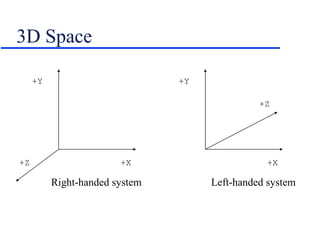
Since all objects are just sets of points, we just
need to translate, scale, rotate the points.
To manipulate a 3D point, use matrix
multiplication.
Translation:
[x’ y’ z’ 1] = [x y z 1] | 1 0 0 0 |
| 0 1 0 0 |
| 0 0 1 0 |
| dx dy dz 1 |](https://image.slidesharecdn.com/3d-150314064843-conversion-gate01/85/3-d-7-320.jpg)
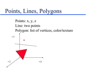
![Scaling
Constant Axis Scaling
[x’ y’ z’ 1] = [x y z 1] | s 0 0 0 |
| 0 s 0 0 |
| 0 0 s 0 |
| 0 0 0 1 |
Variable Axis Scaling
[x’ y’ z’ 1] = [x y z 1] | sx 0 0 0 |
| 0 sy 0 0 |
| 0 0 sz 0 |
| 0 0 0 1 |](https://image.slidesharecdn.com/3d-150314064843-conversion-gate01/85/3-d-8-320.jpg)
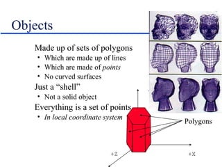
![Rotation
Parallel to x-axis
[x’ y’ z’ 1] = [x y z 1] | 1 0 0 0 |
| 0 cos r sin r 0 |
| 0 -sin r cos r 0 |
| 0 0 0 1 |
Parallel to y-axis
[x’ y’ z’ 1] = [x y z 1] | cos r 0 -sin r 0 |
| 0 1 0 0 |
| sin r 0 cos r 0 |
| 0 0 0 1 |
Parallel to z-axis
[x’ y’ z’ 1] = [x y z 1] | cos r sin r 0 0 |
|-sin r cos r 0 0 |
| 0 0 1 0 |
| 0 0 0 1 |](https://image.slidesharecdn.com/3d-150314064843-conversion-gate01/85/3-d-9-320.jpg)
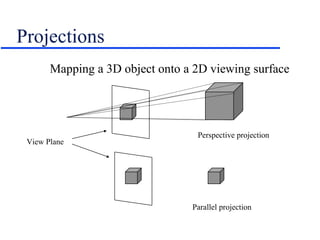
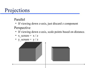
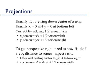
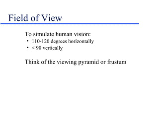
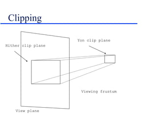
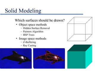
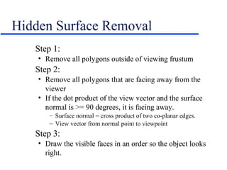
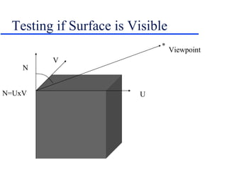
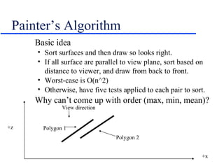
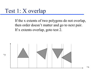
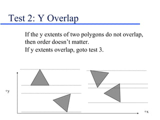
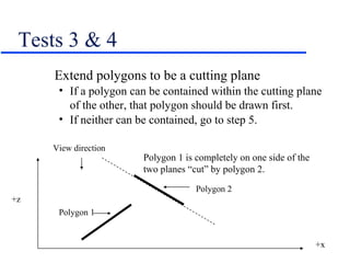
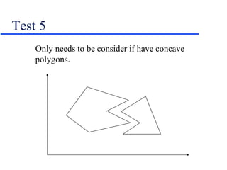
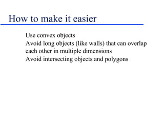
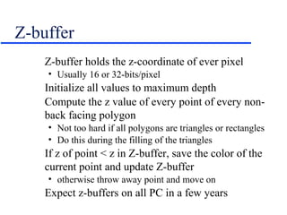
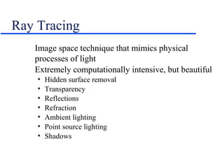
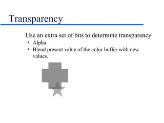

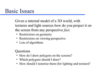
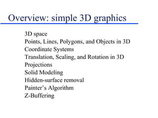
This document provides an introduction and overview of basic 3D graphics concepts including: - Representing 3D objects as points, lines, and polygons in 3D coordinate spaces - Transforming objects using translation, scaling, and rotation matrices - Projecting 3D scenes onto 2D screens using perspective and parallel projections - Techniques for hidden surface removal like the painter's algorithm and z-buffering to determine which polygons are visible.


![Class[5][9th jul] [three js-meshes_geometries_and_primitives]](https://cdn.slidesharecdn.com/ss_thumbnails/class59thjul-threejsmeshesgeometriesandprimitivestemp-210726102924-thumbnail.jpg?width=640&height=640&fit=bounds)