247B3 CATERPILLAR MULTI TERRAIN LOADER SERVICE REPAIR MANUAL TSL
•
0 likes•17 views

CONTAINS HIGH-QUALITY IMAGES, CIRCUIT DIAGRAMS, INSTRUCTIONS SEARCHABLE TEXT, AND BOOKMARKS TO REPAIR, MAINTENANCE, AND SERVICE YOUR MACHINE. THE SAFETY INFORMATION INCLUDES DIAGNOSTIC TESTS, ADJUSTMENTS, AND THEORY OF OPERATION INFORMATION'S. THESE FACTORY SERVICE MANUALS (FSM) ARE THE MANUALS PROVIDED BY MANUFACTURERS WHICH COVER THE SERVICING, MAINTENANCE, AND REPAIR OF THE PRODUCTS. SO THAT THE MECHANICS ARE ABLE TO FIX THEIR OWN PRODUCTS.

Recommended
Recommended
More Related Content
Similar to 247B3 CATERPILLAR MULTI TERRAIN LOADER SERVICE REPAIR MANUAL TSL
Similar to 247B3 CATERPILLAR MULTI TERRAIN LOADER SERVICE REPAIR MANUAL TSL (20)
More from Manual Labs
More from Manual Labs (20)
Recently uploaded
Recently uploaded (20)
247B3 CATERPILLAR MULTI TERRAIN LOADER SERVICE REPAIR MANUAL TSL
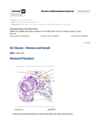
- 1. Previous Screen Shutdown SIS Media Number -UENR0256-00 Publication Date -01/06/2010 Product: MULTI TERRAIN LOADER Model: 247B3 MULTI TERRAIN LOADER TSL Configuration: 247B3 Multi Terrain Loader TSL00001-UP (MACHINE) POWERED BY C2.2 Engine Date Updated -09/06/2010 i 02036664 Disassembly and Assembly 216B3 and 226B3 Skid Steer Loaders and 247B3 Multi Terrain Loader Engine S upp lem ent Removal Procedure Air Cleaner - Remove and Install SMCS - 1051-010 1.Remove harness assembly (2). Loosen hose clamp (3). Disconnect hose (4) . Illustration 1 g01048892
- 2. Tool A Table 1 Required Tools Part NumberPart Description 5P-3413 Pipe Sealant Qty 1 2.Remove bolts (5). Rotate bracket (6). Remove air cleaner assembly (7). Remove service indicator (1) from air cleaner assembly (7) . 1.Apply Tooling (A) to service indicator (1). Install service indicator (1) . 2.Install air cleaner assembly (7) into position. Rotate bracket (6) into position in order to secure the air cleaner assembly. Install bolts (5) . 3.Connect hose (4) onto the air cleaner assembly. Install hose clamp (3). Torque clamp (3) to 4.5 ± .5 N·m (40 ± 4 lb in). 4.Connect harness assembly (2) . Installation Procedure Illustration 2 g01048892 Copyright 1993 - 2022 Caterpillar Inc. All Rights Reserved. Private Network For SIS Licensees. Wed Nov 9 11:15:10 UTC+0530 2022
- 3. Previous Screen Shutdown SIS Media Number -KENR6948-10 Publication Date -01/06/2015 Product: MULTI TERRAIN LOADER Model: 247B3 MULTI TERRAIN LOADER TSL Configuration: 247B3 Multi Terrain Loader TSL00001-UP (MACHINE) POWERED BY C2.2 Engine Date Updated -28/07/2021 i 07360106 Disassembly and Assembly C1.1, C1.5 and C2.2 Engines for Caterpillar Built Machines Removal Procedure Exhaust Manifold - Remove and Install SMCS - 1059-010 Keep all parts clean from contaminants. Contaminants may cause rapid wear and shortened component life. Start By: a.If the engine is equipped with a turbocharger, remove the turbocharger. Refer to Disassembly and Assembly, "Turbocharger - Remove and Install". Note: The three cylinder and the four cylinder engines have different exhaust manifolds. The removal procedure is similar for all models. NOTICE
- 4. Illustration 1 Typical example g01326567 Keep all parts clean from contaminants. Contaminants may cause rapid wear and shortened component life. 1.Loosen nuts (5) and bolts (6). Note: To prevent distortion of the exhaust manifold, loosen the outer fasteners first. 2.Remove nuts (5) and bolts (6). Note: Identify bolts of different lengths so that the bolts can be installed in the correct positions. 3.Remove exhaust manifold (4) from cylinder head (1). Note the orientation of the exhaust manifold for installation. 4.Remove gasket (3) from cylinder head (1). 5.If necessary, remove exhaust manifold studs (2) from cylinder head (1). Installation Procedure NOTICE
- 5. 2.If necessary, install exhaust manifold studs (2) to cylinder head (1). 3.Install a new exhaust manifold gasket (3) to cylinder head (1). 4.Align exhaust manifold (4) with studs (2) and install the exhaust manifold to cylinder head (1). Note: Ensure that the exhaust manifold is installed in the correct orientation. 5.Install nuts (5) and bolts (6) finger tight. Note: Ensure that bolts of different lengths are installed in the correct positions. 6.For the C1.1 and C1.5 engines, tighten nuts (5) and bolts (6) to a torque of 10 N·m (89 lb in). For the C2.2 engine, tighten nuts (5) and bolts (6) to a torque of 25 N·m (18 lb ft). Note: Tighten the inner bolts first. End By: a.If the engine is equipped with a turbocharger, install the turbocharger. Refer to Disassembly and Assembly, "Turbocharger - Remove and Install". Note: The three cylinder and the four cylinder engines have different exhaust manifolds. The installation procedure is similar for all models. 1.Ensure that the mating surfaces of the cylinder head and the exhaust manifold are clean and free from damage. Illustration 2 Typical example g01326567
- 6. Copyright 1993 - 2022 Caterpillar Inc. All Rights Reserved. Private Network For SIS Licensees. Wed Nov 9 11:15:28 UTC+0530 2022
- 7. Previous Screen Shutdown SIS Media Number -KENR6948-10 Publication Date -01/06/2015 Product: MULTI TERRAIN LOADER Model: 247B3 MULTI TERRAIN LOADER TSL Configuration: 247B3 Multi Terrain Loader TSL00001-UP (MACHINE) POWERED BY C2.2 Engine Date Updated -28/07/2021 i 07360106 Disassembly and Assembly C1.1, C1.5 and C2.2 Engines for Caterpillar Built Machines Removal Procedure Exhaust Manifold - Remove and Install SMCS - 1059-010 Keep all parts clean from contaminants. Contaminants may cause rapid wear and shortened component life. Start By: a.If the engine is equipped with a turbocharger, remove the turbocharger. Refer to Disassembly and Assembly, "Turbocharger - Remove and Install". Note: The three cylinder and the four cylinder engines have different exhaust manifolds. The removal procedure is similar for all models. NOTICE
- 8. Illustration 1 Typical example g01326567 Keep all parts clean from contaminants. Contaminants may cause rapid wear and shortened component life. 1.Loosen nuts (5) and bolts (6). Note: To prevent distortion of the exhaust manifold, loosen the outer fasteners first. 2.Remove nuts (5) and bolts (6). Note: Identify bolts of different lengths so that the bolts can be installed in the correct positions. 3.Remove exhaust manifold (4) from cylinder head (1). Note the orientation of the exhaust manifold for installation. 4.Remove gasket (3) from cylinder head (1). 5.If necessary, remove exhaust manifold studs (2) from cylinder head (1). Installation Procedure NOTICE
- 9. 2.If necessary, install exhaust manifold studs (2) to cylinder head (1). 3.Install a new exhaust manifold gasket (3) to cylinder head (1). 4.Align exhaust manifold (4) with studs (2) and install the exhaust manifold to cylinder head (1). Note: Ensure that the exhaust manifold is installed in the correct orientation. 5.Install nuts (5) and bolts (6) finger tight. Note: Ensure that bolts of different lengths are installed in the correct positions. 6.For the C1.1 and C1.5 engines, tighten nuts (5) and bolts (6) to a torque of 10 N·m (89 lb in). For the C2.2 engine, tighten nuts (5) and bolts (6) to a torque of 25 N·m (18 lb ft). Note: Tighten the inner bolts first. End By: a.If the engine is equipped with a turbocharger, install the turbocharger. Refer to Disassembly and Assembly, "Turbocharger - Remove and Install". Note: The three cylinder and the four cylinder engines have different exhaust manifolds. The installation procedure is similar for all models. 1.Ensure that the mating surfaces of the cylinder head and the exhaust manifold are clean and free from damage. Illustration 2 Typical example g01326567
- 10. Copyright 1993 - 2022 Caterpillar Inc. All Rights Reserved. Private Network For SIS Licensees. Wed Nov 9 11:15:21 UTC+0530 2022
- 11. Previous Screen Shutdown SIS Media Number -UENR0256-00 Publication Date -01/06/2010 Product: MULTI TERRAIN LOADER Model: 247B3 MULTI TERRAIN LOADER TSL Configuration: 247B3 Multi Terrain Loader TSL00001-UP (MACHINE) POWERED BY C2.2 Engine Date Updated -09/06/2010 i 02036669 Disassembly and Assembly 216B3 and 226B3 Skid Steer Loaders and 247B3 Multi Terrain Loader Engine S upp lem ent Removal Procedure Muffler - Remove and Install SMCS - 1062-010 1.Remove bolts (6). Remove gasket (5) . 2.Remove nuts (3). Loosen nut (1). Remove muffler (2) . Illustration 1 g01048989
- 12. Required Tools ToolPart Number A 5P-3931 Table 1 Note: Observe the exhaust elbow's position. 3.Remove exhaust elbow (4) . Part Description Anti-Seize Compound Qty 1 1.Install exhaust elbow (4) . 2.Install muffler (2). Tighten nut (1). Install nuts (3) . 3.Apply Tooling (A) to bolts (6). Install gasket (5). Install bolts (6) . Installation Procedure Illustration 2 g01048989 Copyright 1993 - 2022 Caterpillar Inc. All Rights Reserved. Private Network For SIS Licensees. Wed Nov 9 11:15:39 UTC+0530 2022
- 13. Previous Screen Shutdown SIS Media Number -KENR6948-10 Publication Date -01/06/2015 Product: MULTI TERRAIN LOADER Model: 247B3 MULTI TERRAIN LOADER TSL Configuration: 247B3 Multi Terrain Loader TSL00001-UP (MACHINE) POWERED BY C2.2 Engine Date Updated -28/07/2021 i 02602655 Disassembly and Assembly C1.1, C1.5 and C2.2 Engines for Caterpillar Built Machines Removal procedure Turbocharger - Remove and Install SMCS - 1052-010 Note: Plug and cap all open ports and tube assemblies. Keep all parts clean from contaminants. Contaminants may cause rapid wear and shortened component life. Care must be taken to ensure that fluids are contained during performance of inspection, maintenance, testing, adjusting and repair of the product. Be prepared to collect the fluid with suitable containers before opening any compartment or disassembling any component containing fluids. Dispose of all fluids according to local regulations and mandates. NOTICE NOTICE
- 15. Illustration 2 g01304528 1.Loosen hose clamps (5) and remove air inlet hose (1). 2.Remove allen head screws (21) and remove exhaust elbow (19) from turbocharger (4). Remove gasket (18) from the turbocharger. 3.Remove banjo bolt (2) and washers (3). Remove the fasteners and the spacers (not shown) for tube clips (6). Remove bolts (14) and remove tube assembly (13) from the cylinder block. Remove O-ring seal (12). 4.Remove bolts (8) and disconnect tube assembly (10) from the turbocharger. Remove joint (7). If necessary, remove bolts (9) and remove tube assembly (10) from the cylinder block. Remove joint (11). 5.Remove nuts (17) and remove turbocharger (4) from the exhaust manifold. Remove gasket (20) from the exhaust manifold. If necessary, remove studs (15) from the exhaust manifold. Note: Do not use the actuator rod of the wastegate to lift the turbocharger. Installation procedure
- 16. NOTICE Keep all parts clean from contaminants. Contaminants may cause rapid wear and shortened component life. 1.Ensure that the turbocharger is clean and free from damage. Inspect the turbocharger for wear. If the turbocharger is worn, the complete turbocharger must be replaced. 2.Test the actuator for correct operation. Refer to Systems Operation, Testing and Adjusting, "Wastegate - Test" for more information. If the actuator is damaged or the actuator does not operate within the specified limits, the complete turbocharger must be replaced.
- 17. Illustration 3 Illustration 4 g01304121 g01304528 3.Clean the mating surfaces of the exhaust manifold. If necessary, install studs (15) to the exhaust manifold. Tighten the studs to a torque of 18 N·m (13 lb ft). Install a new gasket (20) over the studs. 4.Position turbocharger (4) onto the exhaust manifold. Install nuts (17) and tighten to a torque of 25 N·m (18 lb ft). Note: Do not use the actuator rod of the wastegate to lift the turbocharger . 5.Ensure that tube assemblies (10) and (13) are clean and free from damage. If necessary, replace the tube assemblies. 6.If necessary, position a new joint (11) and tube assembly (10) onto the cylinder block. Install bolts (9). Tighten the bolts finger tight. Position a new joint (7) on tube assembly (10). Align tube assembly (10) to the bottom of the turbocharger. Install bolts (8). Tighten the bolts finger tight.
- 18. Tighten bolts (8) and (9) to a torque of 10 N·m (89 lb in). 7.Lubricate the bearings of turbocharger (4) with clean engine oil through oil inlet port (16). Rotate the shaft of the turbocharger in order to distribute the lubricant. 8.Install a new O-ring seal (12) to tube assembly (13). Position tube assembly (13) against the cylinder block. Install bolts (14). Tighten the bolts to a torque of 10 N·m (89 lb in). 9.Install new washers (3) and banjo bolt (2) to tube assembly (13). Position tube assembly (13) onto turbocharger (4). Tighten the banjo bolt finger tight. 10.If necessary, install the spacer and install the fasteners (not shown) to tube clips (6). Torque the fasteners to 10 N·m (89 lb in). 11.Tighten banjo bolt (2) to a torque of 18 N·m (13 lb ft). Note: Ensure that the tube assembly does not come into contact with any other components. 12.Clean the mating surfaces of exhaust elbow (19). Position a new gasket (18) and exhaust elbow (19) on turbocharger (4). Install allen head screws (21). Tighten the bolts to a torque of 32 N·m (24 lb ft). 13.Ensure that inlet hose (1) is clean and free from defects or restrictions. Loosely install hose clamps (5) to air inlet hose (1). Install the air inlet hose to the connection of the inlet manifold (not shown) and to the turbocharger. Tighten the hose clamps. Copyright 1993 - 2022 Caterpillar Inc. All Rights Reserved. Private Network For SIS Licensees. Wed Nov 9 11:15:47 UTC+0530 2022
- 19. Previous Screen Shutdown SIS Media Number -KENR6947-08 Publication Date -01/06/2015 Product: MULTI TERRAIN LOADER Model: 247B3 MULTI TERRAIN LOADER TSL Configuration: 247B3 Multi Terrain Loader TSL00001-UP (MACHINE) POWERED BY C2.2 Engine Date Updated -06/04/2021 i 08429339 Systems Operation C1.1, C1.5 and C2.2 Engines for Caterpillar Built Machines Air Inlet and Exhaust System SMCS - 1050 Naturally aspirated engines pull outside air through an air cleaner directly into the inlet manifold. The air flows from the inlet manifold to the engine cylinders. The fuel is mixed with the air in the engine cylinders. After the fuel combustion occurs in the engine cylinder, the exhaust gases flow directly to the outside air through the exhaust manifold and the exhaust system. Turbocharged engines pull outside air through an air cleaner into the air intake of the turbocharger. The suction is caused by the turbocharger compressor wheel. Then, the turbocharger compressor wheel compresses the air. The air flows through the inlet manifold which directs an even distribution of the air to each engine cylinder. Air is pulled into the engine cylinder during the intake stroke of the piston. Then, the air is mixed with fuel from the fuel injection nozzles. Each piston makes four strokes: 1.Intake Air is drawn into the cylinder through the open inlet valve. 2.Compression On the compression stroke, the piston moves back up the cylinder and the inlet valves close. The cool air is compressed further. This additional compression generates more heat. 3.Power Fuel is sprayed into the engine by the fuel injection nozzle. The mixture of air and fuel ignites at the top of the compression stroke. The expansion of gases from the combustion forces the piston downward. This force creates the power of the engine. 4.Exhaust
- 20. The piston moves upward to force the gases of combustion from the cylinder through the open exhaust valve. The sequence of the strokes by all the pistons in all the engine cylinders provides constant air flow from the air inlet system during the engine operation. A turbocharger increases the temperature and the density of the air that is sent to the engine cylinder. This condition causes a lower temperature of ignition to develop earlier in the compression stroke. The compression stroke is also timed in a more accurate way with the fuel injection. Surplus air lowers the temperature of combustion. This surplus air also provides internal cooling. A turbocharger improves the following aspects of engine performance: •Power output is increased. •Engine torque is increased. •Engine efficiency is increased. Turbocharger Illustration 1 g00302786
- 21. Components of a turbocharger (typical example) (1) Air intake (2) Compressor housing (3) Compressor wheel (4) Bearing (5) Oil inlet port (6) Bearing (7) Turbine housing (8) Turbine wheel (9) Exhaust outlet (10) Oil outlet port (11) Exhaust inlet A turbocharger is installed between the exhaust and intake manifolds. The turbocharger is driven by exhaust gases which flow through the exhaust inlet (11). The energy of the exhaust gas turns the turbine wheel (8). Then, the exhaust gas flows out of the turbine housing (7) through the exhaust outlet (9). Turbine wheel (8) and compressor wheel (3) are installed on the same shaft. Therefore, turbine wheel (8) and compressor wheel (3) rotate at the same rpm. The compressor wheel is enclosed by compressor housing (2). The compressor wheel compresses the intake air. The intake air flows into the engine cylinders through the inlet valves of the cylinders. The oil from the main gallery of the cylinder block flows through the oil inlet port (5) to lubricate the turbocharger bearings (4) and (6). The pressurized oil passes through the bearing housing of the turbocharger. The oil is returned through the oil outlet port (10) to the oil pan. The turbocharger has a wastegate. The wastegate is controlled by the boost pressure. This allows some of the exhaust gases to bypass the turbine wheel at higher engine speeds. The wastegate is a type of flapper valve that automatically opens at a preset level of boost pressure to allow exhaust gas to flow around the turbine. The wastegate allows the design of the turbocharger to be more effective at lower engine speeds. Cylinder Head And Valves
- 22. Illustration 2g00905459 Cross section of the inlet and exhaust valves in the cylinder head (typical example)
- 23. Illustration 3 Cylinder head and valves (typical example) (1) Collets (2) Valve spring retainer (3) Valve spring (4) Valve seal (5) Valve guide (6) Cylinder head (7) Cylinder head gasket (8) Pushrod (9) Lifter (10) Exhaust valve (11) Inlet valve g00905464 The valves and the rocker shaft assembly control the flow of air into the cylinders and out of the cylinders during engine operation. The cylinder head assembly has two valves for each cylinder. Each valve has one valve spring (3). The ports for inlet valve (11) and exhaust valve (10) are on the left side of the cylinder head. The valve moves along a steel valve guide (5). The inlet valve and the exhaust valve are opened and closed by the rotation and movement of the following components:
- 24. •Crankshaft •Idler gear •Camshaft •Valve lifters •Pushrods •Rocker arms •Valve springs The camshaft gear is driven by the idler gear. The camshaft gear, the idler gear, and the crankshaft gear are timed together. When the camshaft turns, the valve lifters are moved up and down. The pushrods move the rocker arms. The rocker arms make the inlet valves and the exhaust valves open and close. This is in sequence with the firing order of the engine. The valve springs force the valves back to the closed position. The valve mechanism cover contains a closed crankcase breather assembly. The gases in the valve cover, which are caused by blowby, pass from the crankcase to the inlet manifold. The breather is sealed from the outside air by a diaphragm. Above the diaphragm, the cover is vented to the outside air by a small vent hole so that pressure does not build up. Crankcase Breather Copyright 1993 - 2022 Caterpillar Inc. All Rights Reserved. Private Network For SIS Licensees. Wed Nov 9 11:14:33 UTC+0530 2022
- 25. Previous Screen Shutdown SIS Media Number -KENR6947-08 Publication Date -01/06/2015 Product: MULTI TERRAIN LOADER Model: 247B3 MULTI TERRAIN LOADER TSL Configuration: 247B3 Multi Terrain Loader TSL00001-UP (MACHINE) POWERED BY C2.2 Engine Date Updated -06/04/2021 i 01592413 Testing and Adjusting C1.1, C1.5 and C2.2 Engines for Caterpillar Built Machines Air Inlet and Exhaust System - Inspect Making contact with a running engine can cause burns from hot parts and can cause injury from rotating parts. When working on an engine that is running, avoid contact with hot parts and rotating parts. Hot engine components can cause injury from burns. Before performing maintenance on the engine, allow the engine and the components to cool. 1.Inspect the engine air cleaner inlet and ducting in order to ensure that the passageway is not blocked or collapsed. SMCS - 1050-040 A general visual inspection should be made to the air inlet and exhaust system. Make sure that there are no signs of leaks in the system. There will be a reduction in the performance of the engine if there is a restriction in the air inlet system or the exhaust system.
- 26. 2.Inspect the engine air cleaner element. Replace a dirty engine air cleaner element with a clean engine air cleaner element. 3.Check for dirt tracks on the clean side of the engine air cleaner element. If dirt tracks are observed, contaminants are flowing past the engine air cleaner element and/or the seal for the engine air cleaner element. 4.For engines with plastic valve mechanism covers, if you experience excessive crankcase pressure, remove the valve mechanism cover and check the end of the shroud for a skin of plastic. If the end of the shroud has a skin of plastic, remove the skin of plastic. Ensure that all of the debris is removed. 5.If the breather tube is made of plastic, use low pressure air to check for a blockage in the breather tube. If a blockage is inside of the connector, the cover assembly must be replaced. A broken valve mechanism cover will result if you try to remove the connection. Copyright 1993 - 2022 Caterpillar Inc. All Rights Reserved. Private Network For SIS Licensees. Wed Nov 9 11:14:46 UTC+0530 2022
- 27. Previous Screen Shutdown SIS Media Number -KENR6947-08 Copyright 1993 - 2022 Caterpillar Inc. All Rights Reserved. Private Network For SIS Licensees. Publication Date -01/06/2015 Product: MULTI TERRAIN LOADER Model: 247B3 MULTI TERRAIN LOADER TSL Configuration: 247B3 Multi Terrain Loader TSL00001-UP (MACHINE) POWERED BY C2.2 Engine Date Updated -06/04/2021 i 02282179 Wed Nov 9 11:15:02 UTC+0530 2022 Testing and Adjusting C1.1, C1.5 and C2.2 Engines for Caterpillar Built Machines Exhaust Temperature - Test Measure the Exhaust Temperature SMCS - 1088-081 Table 1 Required Tools Part NumberPart NameQty 164-3310 Laser Infrared Thermometer 1 When the engine runs at low idle, the temperature of an exhaust manifold port can indicate the condition of a fuel injection nozzle. A low temperature indicates that no fuel is flowing to the cylinder. An inoperative fuel injection nozzle or a problem with the fuel injection pump could cause this low temperature. A very high temperature can indicate that too much fuel is flowing to the cylinder. A malfunctioning fuel injection nozzle could cause this very high temperature. Use the 164-3310 Laser Infrared Thermometer to check this exhaust temperature at the exhaust outlet for each cylinder. Compare the temperature readings for each exhaust outlet. Investigate any difference in the temperature readings.
- 28. Previous Screen Shutdown SIS Media Number -KENR6947-08 Publication Date -01/06/2015 Product: MULTI TERRAIN LOADER Model: 247B3 MULTI TERRAIN LOADER TSL Configuration: 247B3 Multi Terrain Loader TSL00001-UP (MACHINE) POWERED BY C2.2 Engine Date Updated -06/04/2021 i 02590483 Testing and Adjusting C1.1, C1.5 and C2.2 Engines for Caterpillar Built Machines Wastegate - Test Inspection of the Wastegate SMCS - 1057-081 Hot engine components can cause injury from burns. Before performing maintenance on the engine, allow the engine and the components to cool. Note: The turbocharger is a nonserviceable item. The pressure for the wastegate can be checked but not adjusted. Before the wastegate is tested, be sure that the inlet air restriction is within the specifications for your engine. Be sure that the exhaust system restriction is within the specifications for your engine. Refer to Systems Operation, Testing and Adjusting, "Air Inlet and Exhaust System - Inspect". The wastegate controls the amount of exhaust gas that is allowed to bypass the turbine side of the turbocharger. This valve then controls the rpm of the turbocharger. When the engine operates in conditions of low boost, a spring presses against a diaphragm in the canister. The actuating rod will move and the wastegate will close. Then, the turbocharger can operate at maximum performance. When the boost pressure increases against the diaphragm in the canister, the wastegate will open. The rpm of the turbocharger becomes limited. The rpm is limited because a portion of the exhaust gases bypass the turbine wheel of the turbocharger.
- 29. The following levels of boost pressure indicate a problem with the wastegate: •Too high in full load conditions •Too low in all low boost conditions The boost pressure controls the maximum rpm of the turbocharger, because the boost pressure controls the position of the wastegate. The following factors also affect the maximum rpm of the turbocharger: •The engine rating •The horsepower demand on the engine •The high idle rpm •Inlet air restriction •Exhaust system restriction 1.Remove the heat shield from the turbocharger. Remove the guard for the wastegate. 2.Remove the boost line from the wastegate. Connect an air supply to the wastegate that can be adjusted accurately. 3.Fasten a suitable dial gauge to the turbocharger so that the end of the actuator rod is in contact with the plunger of the dial gauge. This will measure axial movement of the actuator rod. 4.Slowly apply air pressure to the wastegate so that the actuator rod moves 1.0 mm (0.039 inch). The air pressure should be approximately 52 kPa (7.5421 psi). Ensure that the dial gauge returns to zero when the air pressure is released. Repeat the test several times. This will ensure that an accurate reading is obtained. 5.Consult your nearest approved Caterpillar dealer or your nearest approved Caterpillar distributor if the operation of the wastegate is not correct. Test the Wastegate for Proper Operation Copyright 1993 - 2022 Caterpillar Inc. All Rights Reserved. Private Network For SIS Licensees. Wed Nov 9 11:14:55 UTC+0530 2022
- 30. Previous Screen Shutdown SIS Media Number -KENR6948-10 Publication Date -01/06/2015 Product: MULTI TERRAIN LOADER Model: 247B3 MULTI TERRAIN LOADER TSL Configuration: 247B3 Multi Terrain Loader TSL00001-UP (MACHINE) POWERED BY C2.2 Engine Date Updated -28/07/2021 i 02237832 Disassembly and Assembly C1.1, C1.5 and C2.2 Engines for Caterpillar Built Machines Measurement Procedure Bearing Clearance - Check A Tool SMCS - 1203-535; 1219-535 Table 1 Required Tools Part NumberPart DescriptionQty Plastic Gauge (Green) 198-9142 0.025 to 0.076 mm 1 (0.001 to 0.003 inch) Plastic Gauge (Red) 198-9143 0.051 to 0.152 mm 1 (0.002 to 0.006 inch) Plastic Gauge (Blue) 198-9144 0.102 to 0.229 mm 1 (0.004 to 0.009 inch) Plastic Gauge (Yellow) 198-9145 0.230 to 0.510 mm 1 (0.009 to 0.020 inch) Keep all parts clean from contaminants. NOTICE
- 31. For the full PDF version of this manual, Please click on the above download PDF button. WEBSITE - WWW.MANUALLABS.COM