TH63 CATERPILLAR TELEHANDLER SERVICE REPAIR MANUAL 3NN
•
0 likes•15 views

The TH63 CATERPILLAR TELEHANDLER SERVICE REPAIR MANUAL 3NN offers a comprehensive, detailed guide to servicing and repairing telehandlers. Covering all major component systems, it is an invaluable tool for installing, troubleshooting, diagnosing, and maintaining optimal operational performance.

Recommended
Recommended
More Related Content
Similar to TH63 CATERPILLAR TELEHANDLER SERVICE REPAIR MANUAL 3NN
Similar to TH63 CATERPILLAR TELEHANDLER SERVICE REPAIR MANUAL 3NN (8)
More from Manual Labs
More from Manual Labs (20)
Recently uploaded
Recently uploaded (20)
TH63 CATERPILLAR TELEHANDLER SERVICE REPAIR MANUAL 3NN
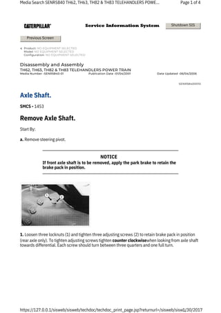
- 1. SMCS - 1453 Start By: a. Remove steering pivot. If front axle shaft is to be removed, apply the park brake to retain the brake pack in position. Media Search SENR5840 TH62, TH63, TH82 & TH83 TELEHANDLERS POWE... https://127.0.0.1/sisweb/sisweb/techdoc/techdoc_print_page.jsp?returnurl=/sisweb/sisw... Page 1 of 4 1/30/2017 1. Loosen three locknuts (1) and tighten three adjusting screws (2) to retain brake pack in position (rear axle only). To tighten adjusting screws tighten counter clockwisewhen looking from axle shaft towards differential. Each screw should turn between three quarters and one full turn. Disassembly and Assembly TH62, TH63, TH82 & TH83 TELEHANDLERS POWER TRAIN Axle Shaft. Remove Axle Shaft. Previous Screen Shutdown SIS Media Number -SENR5840-01 Product: NO EQUIPMENT SELECTED Model: NO EQUIPMENT SELECTED Configuration: NO EQUIPMENT SELECTED Publication Date -01/04/2001 Date Updated -06/04/2006 SENR58400010 NOTICE
- 2. 2. Remove locknut (3). 3. Remove retaining screw (4). 4. Withdraw the axle shaft (5) from the axle and remove the 'O' ring seal (6).. 5. Remove circlip (7) and separate the axle shaft from the reducing bushing assembly. Media Search SENR5840 TH62, TH63, TH82 & TH83 TELEHANDLERS POWE... https://127.0.0.1/sisweb/sisweb/techdoc/techdoc_print_page.jsp?returnurl=/sisweb/sisw... Page 2 of 4 1/30/2017
- 3. 6. Remove the circlip (8) from the reducing bushing assembly. 7. Remove the bearing (9), seal (10) and circlip (11) from the reducing bush. Install Axle Shaft. 2. Position the reducing bushing assembly onto the axle shaft (5) and install circlip (7). 3. Install 'O' ring seal (6). Media Search SENR5840 TH62, TH63, TH82 & TH83 TELEHANDLERS POWE... https://127.0.0.1/sisweb/sisweb/techdoc/techdoc_print_page.jsp?returnurl=/sisweb/sisw... 1. Assemble the circlip (11), seal (10), bearing (9) and circlip (8) into the reducing bushing assembly. Page 3 of 4 1/30/2017
- 4. Media Search SENR5840 TH62, TH63, TH82 & TH83 TELEHANDLERS POWE... https://127.0.0.1/sisweb/sisweb/techdoc/techdoc_print_page.jsp?returnurl=/sisweb/sisw... 4. Install the axle shaft into the axle. It may be necessary to rotate the axle shaft to align the splines. 5. Install the retaining screw (4) and locknut (3). Tighten the locknut to a torque of ... 86 Nm (64.5 lb.ft.). 6. Screw the brake adjusting screws (2) clockwisethree quarters of a turn to set the brake clearance and secure with locknuts (1). End by: a. Install steering pivot. Page 4 of 4 1/30/2017 Copyright 1993 - 2017 Caterpillar Inc. All Rights Reserved. Private Network For SIS Licensees. Mon Jan 30 13:55:24 UTC+0700 2017
- 5. SMCS - 1453 Start By: a. Remove axle. b. Remove steering tie rods. Media Search SENR5840 TH62, TH63, TH82 & TH83 TELEHANDLERS POWE... https://127.0.0.1/sisweb/sisweb/techdoc/techdoc_print_page.jsp?returnurl=/sisweb/sisw... 1. Remove nuts (1) and remove axle housing (2) from each side of the axle, complete with brake discs and axle shafts. Page 1 of 8 1/30/2017 Disassembly and Assembly TH62, TH63, TH82 & TH83 TELEHANDLERS POWER TRAIN Differential. Remove Differential. Previous Screen Shutdown SIS Media Number -SENR5840-01 Product: NO EQUIPMENT SELECTED Model: NO EQUIPMENT SELECTED Configuration: NO EQUIPMENT SELECTED Publication Date -01/04/2001 Date Updated -06/04/2006 SENR58400013
- 6. 4. Remove four shoulder studs (6) from each side of the differential housing. 3. Using special tool (C), remove the adjusting nut (5) from each end housing. Media Search SENR5840 TH62, TH63, TH82 & TH83 TELEHANDLERS POWE... https://127.0.0.1/sisweb/sisweb/techdoc/techdoc_print_page.jsp?returnurl=/sisweb/sisw... 5. Support the differential and remove both end housings (7). Remove two 'O' ring seals (8) from each housing. 2. Knock back the locking tabs (3), remove the bolts (4) and locking tabs from each end housing. Page 2 of 8 1/30/2017
- 7. 8. Remove seal (13). 9. Using special tools (A) and (B), remove ring nut (14). 7. Using special tool (A), remove flange nut (10), flange (11) and seal cover (12). Media Search SENR5840 TH62, TH63, TH82 & TH83 TELEHANDLERS POWE... https://127.0.0.1/sisweb/sisweb/techdoc/techdoc_print_page.jsp?returnurl=/sisweb/sisw... 6. Remove the differential (9) taking care not to damage the machined surfaces of the differential housing. Page 3 of 8 1/30/2017
- 8. 12. Press the bearing (19) off the pinion. 11. Remove the spacer (17) and shim (18). 10. Remove the pinion (15) and bearing (16) from the differential housing. 13. Extract the two bearing cups (20) and shim (21) from the differential housing. Media Search SENR5840 TH62, TH63, TH82 & TH83 TELEHANDLERS POWE... https://127.0.0.1/sisweb/sisweb/techdoc/techdoc_print_page.jsp?returnurl=/sisweb/sisw... Page 4 of 8 1/30/2017 Install Differential
- 9. 2. Press bearing (19) on pinion (15). 3. Install shim (18) and spacer (17) on pinion. 4. Install pinion (15) and bearing (16) in differential housing. 1. Install shim (21) and two bearing cups (20) in differential housing. Refer to topic, "Pinion Depth Adjustment" in Power Train System Testing and Adjusting Manual, Form No. SENR5839, for correct shimming procedure and use of special tool (D). Refer to topic; "Pinion Bearing Preload Adjustment" in Power Train System Testing and Adjusting Manual, Form No. SENR5839, for correct shimming procedure and use of special tool (D). Media Search SENR5840 TH62, TH63, TH82 & TH83 TELEHANDLERS POWE... Prior to assembly make sure all components are clean. Precision fitted components will be damaged by foreign material. https://127.0.0.1/sisweb/sisweb/techdoc/techdoc_print_page.jsp?returnurl=/sisweb/sisw... Page 5 of 8 1/30/2017 NOTICE NOTICE NOTICE
- 10. 6. Install seal (13). Refer to topic "Pinion Bearing Preload Adjustment" in Power Train Testing and Adjusting, Form No. SENR5839, and check pinion preload. Media Search SENR5840 TH62, TH63, TH82 & TH83 TELEHANDLERS POWE... https://127.0.0.1/sisweb/sisweb/techdoc/techdoc_print_page.jsp?returnurl=/sisweb/sisw... 7. Apply 9S3263thread lock to threads of the pinion, and using special tool (A), install seal cover (12), flange (11) and nut (10). Torque tighten nut to ... 600-700Nm (440-520 lb.ft) Page 6 of 8 1/30/2017 5. Apply 9S3263thread lock to threads of pinion and, using special tools (A) and (B), install ring nut (14). Torque tighten ring nut to ... 600 - 700Nm (440 - 520 lb.ft.). NOTICE
- 11. 10. Install four shoulder studs (6) in each end housing (7). Refer to topic 'Differential Backlash and Tooth Engagement Contact Pattern Adjustment' in Power Train System Testing and Adjusting Manual, Form No. SENR5839, for correct pinion to bevel gear backlash adjustment. Media Search SENR5840 TH62, TH63, TH82 & TH83 TELEHANDLERS POWE... https://127.0.0.1/sisweb/sisweb/techdoc/techdoc_print_page.jsp?returnurl=/sisweb/sisw... 8. Install the differential (9) in the differential housing taking care not to damage the machined surfaces of the differential housing. 11. Apply 9S3263thread lock to the threads of adjusting nuts (5) and using special tool (C), install adjusting nuts. Page 7 of 8 1/30/2017 9. Install the two 'O' ring seals (8) on each end housing (7). Support the differential (9) and install the two end housings (7). NOTICE
- 12. 13. Install axle housing (2) to each side of the axle and install nuts (1). Media Search SENR5840 TH62, TH63, TH82 & TH83 TELEHANDLERS POWE... https://127.0.0.1/sisweb/sisweb/techdoc/techdoc_print_page.jsp?returnurl=/sisweb/sisw... 12. Install locking tabs (3) and bolts (4). Bend over the locking tabs to secure adjusting nuts (5). Page 8 of 8 1/30/2017 Copyright 1993 - 2017 Caterpillar Inc. All Rights Reserved. Private Network For SIS Licensees. Mon Jan 30 13:55:51 UTC+0700 2017
- 13. SMCS - 1453 Media Search SENR5840 TH62, TH63, TH82 & TH83 TELEHANDLERS POWE... https://127.0.0.1/sisweb/sisweb/techdoc/techdoc_print_page.jsp?returnurl=/sisweb/sisw... 1. Remove the four bolts (1), two half caps (2) and disconnect the drive shaft from the axle. 2. Remove the four bolts (3), two half caps (4) and disconnect the drive shaft from the transfer gearbox. Page 1 of 2 1/30/2017 1. Position the drive shaft on the transfer gearbox yoke, install two half caps (4) and four bolts (3). Torque tighten bolts to ... 42 - 52Nm (31.5 - 39.0 lb.ft.). 2. Position drive shaft on axle yoke, install two half caps (2) and four bolts (1). Torque tighten bolts Disassembly and Assembly TH62, TH63, TH82 & TH83 TELEHANDLERS POWER TRAIN Drive Shafts. Install Front and Rear Drive Shafts. Remove Front and Rear Drive Shafts. Previous Screen Shutdown SIS Media Number -SENR5840-01 Product: NO EQUIPMENT SELECTED Model: NO EQUIPMENT SELECTED Configuration: NO EQUIPMENT SELECTED Publication Date -01/04/2001 Date Updated -06/04/2006 SENR58400004
- 14. to ... 42 - 52 Nm 31.5 - 39.0 lb.ft.). 2. Remove four bolts (2) and disconnect drive shaft from transmission. 1. Remove four bolts (1) and disconnect drive shaft from transfer gearbox. Media Search SENR5840 TH62, TH63, TH82 & TH83 TELEHANDLERS POWE... https://127.0.0.1/sisweb/sisweb/techdoc/techdoc_print_page.jsp?returnurl=/sisweb/sisw... Page 2 of 2 1/30/2017 1. Position drive shaft on transmission yoke and install four bolts (2). Torque tighten bolts to ... 42 - 52Nm (31.5 to 39.0 lb.ft.). 2. Position drive shaft on transfer gearbox yoke and install four bolts (1). Torque tighten bolts to ... 42 - 52Nm (31.5 - 39.0 lb.ft.). Install Transmission Output Drive Shaft. Remove Transmission Output Drive Shaft. Copyright 1993 - 2017 Caterpillar Inc. All Rights Reserved. Private Network For SIS Licensees. Mon Jan 30 13:52:59 UTC+0700 2017
- 15. SMCS - 1453 Start By: a. Remove battery. b. Remove radiator. 2. Disconnect electrical cables (5) from alternator. https://127.0.0.1/sisweb/sisweb/techdoc/techdoc_print_page.jsp?returnurl=/sisweb/sisw... 1. Remove four nuts (1), bolts (2) and washers (3) and remove hood and hood support (4). Media Search SENR5840 TH62, TH63, TH82 & TH83 TELEHANDLERS POWE...Page 1 of 14 1/30/2017 Disassembly and Assembly TH62, TH63, TH82 & TH83 TELEHANDLERS POWER TRAIN Engine and Transmission Remove Engine and Transmission. Previous Screen Shutdown SIS Media Number -SENR5840-01 Product: NO EQUIPMENT SELECTED Model: NO EQUIPMENT SELECTED Configuration: NO EQUIPMENT SELECTED Publication Date -01/04/2001 Date Updated -06/04/2006 SENR58400001
- 16. 5. Disconnect air intake hose (12) from beneath air cleaner assembly. 3. Remove three nuts (6), washers (7) and disconnect exhaust pipe (8). https://127.0.0.1/sisweb/sisweb/techdoc/techdoc_print_page.jsp?returnurl=/sisweb/sisw... 6. Remove bolt (13), washer (14) and clip (15) and detach battery cables from transmission. Media Search SENR5840 TH62, TH63, TH82 & TH83 TELEHANDLERS POWE...Page 2 of 14 1/30/2017 4. Disconnect electrical cables (9) from starter motor solenoid. Remove nut (10) and disconnect earth cable (11).
- 17. 8. Disconnect hose (20) from radiator expansion tank. 10. Disconnect two oil cooler hoses (24) and (25) from transmission. 7. Disconnect four hydraulic hoses (16), (17), (18) and (19) from hydraulic pump. 9. Remove three bolts (21), washers (22) and remove expansion tank and bracket (23). https://127.0.0.1/sisweb/sisweb/techdoc/techdoc_print_page.jsp?returnurl=/sisweb/sisw... Media Search SENR5840 TH62, TH63, TH82 & TH83 TELEHANDLERS POWE...Page 3 of 14 1/30/2017
- 18. 11. Remove bolt (26), clamp (27) and detach oil cooler hoses from engine. 13. Disconnect five electrical connectors (32) from transmission solenoids. 14. Disconnect electrical connection (33) from transmission oil temperature switch. https://127.0.0.1/sisweb/sisweb/techdoc/techdoc_print_page.jsp?returnurl=/sisweb/sisw... Media Search SENR5840 TH62, TH63, TH82 & TH83 TELEHANDLERS POWE...Page 4 of 14 1/30/2017 12. Remove nut (28), washer (29), bolt (30) and clamp (31) and detach hydraulic delivery hose (19) from engine.
- 19. 17. Disconnect hose (36) from secondary fuel filter. 16. Disconnect hose (35) from the primary fuel filter. 15. Disconnect two hoses (34) from windscreen washer bottle. https://127.0.0.1/sisweb/sisweb/techdoc/techdoc_print_page.jsp?returnurl=/sisweb/sisw... 18. Remove spring (37), nut (38) and washer (39) and detach accelerator cable from fuel pump. Remove two nuts (40), 'U' clamp (41) and saddle (42) and detach accelerator cable from engine bracket. Media Search SENR5840 TH62, TH63, TH82 & TH83 TELEHANDLERS POWE...Page 5 of 14 1/30/2017
- 20. 20. Disconnect hose (45) from water pump. 19. Disconnect two heater hoses (43) and (44). 22. Disconnect one cable (48) from water temperature switch. https://127.0.0.1/sisweb/sisweb/techdoc/techdoc_print_page.jsp?returnurl=/sisweb/sisw... 21. Disconnect one cable (46) from oil temperature switch. Disconnect one cable (47) from oil pressure switch. Media Search SENR5840 TH62, TH63, TH82 & TH83 TELEHANDLERS POWE...Page 6 of 14 1/30/2017
- 21. 23. Remove four bolts (49) and disconnect drive shaft from transmission. 24. Remove bolt (50) and detach earth cable (51) from front engine mounting. 25. Disconnect the four electrical harnesses (52) from the connectors on the chassis. https://127.0.0.1/sisweb/sisweb/techdoc/techdoc_print_page.jsp?returnurl=/sisweb/sisw... 26. Remove four nuts (53), rubber faced washers (54), bolts (55) and washers (56) from engine mountings. 27. Attach suitable lifting equipment to engine and transmission. Media Search SENR5840 TH62, TH63, TH82 & TH83 TELEHANDLERS POWE...Page 7 of 14 1/30/2017
- 22. 5. Connect the four electrical harnesses (52) to the connectors on the chassis. 4. Connect the earth cable (51) to the front engine mounting and secure with bolt (50). https://127.0.0.1/sisweb/sisweb/techdoc/techdoc_print_page.jsp?returnurl=/sisweb/sisw... 1. Check that the four engine mounting rubbers are located in the mounting holes and lower the engine and transmission into the frame. 2. Install the bolts (55), rubber faced washers (54), washers (56) and nuts (53). The rubber faced washers must be installed underneath the mounting brackets with the rubber face uppermost. 3. Torque tighten nuts to ... 90 - 100Nm (67.5 - 75.0 lb.ft.). 28. Ensure all cable ties attaching electrical harnesses and hoses to engine and transmission are removed. Position electrical harnesses and hoses along the sub-frame away from the engine and transmission. 29. Using the lifting equipment, raise the engine and transmission from the sub-frame and remove from the machine. Weight of engine and transmission is approximately ... 660Kg (1452 lbs). Media Search SENR5840 TH62, TH63, TH82 & TH83 TELEHANDLERS POWE...Page 8 of 14 1/30/2017 Install Engine and Transmission
- 23. 9. Connect hose (45) to the water pump. 7. Connect the cable (48) to the water temperature switch. https://127.0.0.1/sisweb/sisweb/techdoc/techdoc_print_page.jsp?returnurl=/sisweb/sisw... 6. Position the drive shaft on the transmission and secure with four bolts (49). Torque tighten bolts to ... 42 - 52Nm (31.5 - 39.0 lb.ft.). 8. Connect the cable (47) to the oil pressure switch and the cable (46) to the oil temperature switch. Media Search SENR5840 TH62, TH63, TH82 & TH83 TELEHANDLERS POWE...Page 9 of 14 1/30/2017
- 24. 10. Connect the two heater hoses (44) and (43). 13. Connect the hose (35) to the primary fuel filter. 12. Connect the hose (36) to the secondary fuel filter. Media Search SENR5840 TH62, TH63, TH82 & TH83 TELEHANDLERS PO... https://127.0.0.1/sisweb/sisweb/techdoc/techdoc_print_page.jsp?returnurl=/sisweb/sisw... Page 10 of 14 1/30/2017 11. Connect the accelerator cable to the fuel pump and secure with the washer (39) and nut (38). Install spring (37). Position the accelerator cable on the engine bracket and loosely install the saddle (42), 'U' clamp (41) and nuts (40). Slide the cable toward the transmission to remove any slack and secure the two nuts (40).
- 25. 14. Connect the two hoses (34) to the windscreen washer bottle. 15. Connect the cable (33) to the transmission oil temperature switch. 17. Connect the two oil cooler hoses (25) and (24) to the transmission. Media Search SENR5840 TH62, TH63, TH82 & TH83 TELEHANDLERS PO... https://127.0.0.1/sisweb/sisweb/techdoc/techdoc_print_page.jsp?returnurl=/sisweb/sisw... 16. Connect the five electrical connectors (32) to the transmission solenoids in the order noted on disassembly. Page 11 of 14 1/30/2017
- 26. 18. Secure the oil cooler hoses to the engine with the clamp (27) and bolt (26). Media Search SENR5840 TH62, TH63, TH82 & TH83 TELEHANDLERS PO... 19. Connect the four hydraulic hoses (16), (17), (18) and (19) to the hydraulic pump. https://127.0.0.1/sisweb/sisweb/techdoc/techdoc_print_page.jsp?returnurl=/sisweb/sisw... 21. Install the expansion tank and bracket (23) and secure with bolts (21) and washers (22). Page 12 of 14 1/30/2017 20. Secure the hydraulic delivery hose to the transmission with the clamp (31), bolt (30), washer (29) and nut (28).
- 27. 22. Connect hose (20) to the bottom of the expansion tank. 24. Connect the air intake hose (12) to the base of the air cleaner. Media Search SENR5840 TH62, TH63, TH82 & TH83 TELEHANDLERS PO... https://127.0.0.1/sisweb/sisweb/techdoc/techdoc_print_page.jsp?returnurl=/sisweb/sisw... 23. Secure the battery cables to the transmission with the clip (15), washer (14) and bolt (13). 25. Install the earth cable (11) to the starter motor mounting stud and secure with nut (10). Connect electrical cables (9) to starter motor solenoid. Page 13 of 14 1/30/2017
- 28. 27. Connect electrical cables (5) to alternator. Media Search SENR5840 TH62, TH63, TH82 & TH83 TELEHANDLERS PO... 28. Install hood and hood support (4) and secure with bolts (3), washers (2) and nuts (1). 29. Secure all cables and hoses where necessary with cable ties. End By; a. Install radiator. b. Install battery. https://127.0.0.1/sisweb/sisweb/techdoc/techdoc_print_page.jsp?returnurl=/sisweb/sisw... 26. Position the exhaust pipe (8) on the exhaust manifold and secure the washers (7) and nuts (6). Page 14 of 14 1/30/2017 Copyright 1993 - 2017 Caterpillar Inc. All Rights Reserved. Private Network For SIS Licensees. Mon Jan 30 13:50:48 UTC+0700 2017
- 29. SMCS - 1453 Start By. a. Remove wheel. 3. Inspect the 'O' ring seal (4) on the hub and replace if necessary. 4. Remove the pinion gear (5) and washer (6) from the hub. Media Search SENR5840 TH62, TH63, TH82 & TH83 TELEHANDLERS POWE... https://127.0.0.1/sisweb/sisweb/techdoc/techdoc_print_page.jsp?returnurl=/sisweb/sisw... Page 1 of 6 1/30/2017 1. Position drain plug (1) at the bottom. Remove plug (1) and drain oil. 2. Remove bolts (2) and remove final drive from the hub. The thrust washer (3) should remain in the final drive. Disassembly and Assembly TH62, TH63, TH82 & TH83 TELEHANDLERS POWER TRAIN Final Drive. Remove Final Drive. Previous Screen Shutdown SIS Media Number -SENR5840-01 Product: NO EQUIPMENT SELECTED Model: NO EQUIPMENT SELECTED Configuration: NO EQUIPMENT SELECTED Publication Date -01/04/2001 Date Updated -06/04/2006 SENR58400011
- 30. Start by: Install Final Drive. 1. Install the washer (6) and pinion gear (5) into the hub. 2. Check that the 'O' ring seal (4) is undamaged and correctly positioned on the hub. Media Search SENR5840 TH62, TH63, TH82 & TH83 TELEHANDLERS POWE... Prior to assembly make sure all components are clean. Precision fitted components will be damaged by foreign material. https://127.0.0.1/sisweb/sisweb/techdoc/techdoc_print_page.jsp?returnurl=/sisweb/sisw... 3. Check that the thrust washer(3) is correctly located in the center and install final drive. 4. Install bolts (2) and torque tighten to ... 49Nm (36 lb.ft.). 5. Install drain plug (1) and torque tighten to ... 120Nm (90 lb.ft.). 6. Fill the final drive with the specified lubricant as detailed in the Operation and Maintenance Manual Form No. SEBU6885. Disassemble Final Drive. Page 2 of 6 1/30/2017 NOTICE
- 31. a. Remove final drive. 1. Remove circlip (1) using Tool (A). Media Search SENR5840 TH62, TH63, TH82 & TH83 TELEHANDLERS POWE... https://127.0.0.1/sisweb/sisweb/techdoc/techdoc_print_page.jsp?returnurl=/sisweb/sisw... Page 3 of 6 1/30/2017 4. Remove pinion gear (7) and washer (8) from the hub. Remove the four bolts (9) and locking plate (10) from the ring gear support. 2. Press out the three pins (2) and remove the gears and thrust washer from inside the pinion housing. 3. Remove two bearings (3) and one spacer (4) from each gear (5). Remove one 'O' ring seal (6) from each pin (2).
- 32. For the full PDF version of this manual, Please click on the above download PDF button. WEBSITE - WWW.MANUALLABS.COM