
More Related Content
What's hot
What's hot (8)
Similar to 2013 kawasaki brute force kvf750 gd service repair manual
Similar to 2013 kawasaki brute force kvf750 gd service repair manual (7)
More from fhjsekkemm
More from fhjsekkemm (20)
Recently uploaded
Recently uploaded (20)
2013 kawasaki brute force kvf750 gd service repair manual
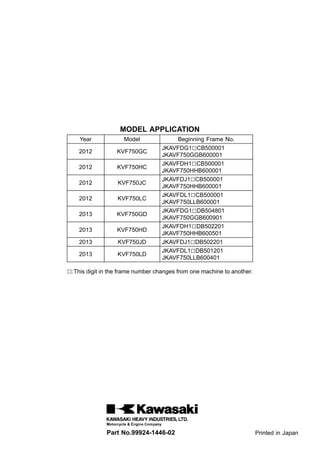
- 1. MODEL APPLICATION Year Model Beginning Frame No. 2012 KVF750GC JKAVFDG1□CB500001 JKAVF750GGB600001 2012 KVF750HC JKAVFDH1□CB500001 JKAVF750HHB600001 2012 KVF750JC JKAVFDJ1□CB500001 JKAVF750HHB600001 2012 KVF750LC JKAVFDL1□CB500001 JKAVF750LLB600001 2013 KVF750GD JKAVFDG1□DB504801 JKAVF750GGB600901 2013 KVF750HD JKAVFDH1□DB502201 JKAVF750HHB600501 2013 KVF750JD JKAVFDJ1□DB502201 2013 KVF750LD JKAVFDL1□DB501201 JKAVF750LLB600401 □:This digit in the frame number changes from one machine to another. Part No.99924-1446-02 Printed in Japan
- 2. BRUTE FORCE 750 4×4i EPS BRUTE FORCE 750 4×4i KVF750 4×4 EPS KVF750 4×4 All Terrain Vehicle Service Manual
- 3. This quick reference guide will assist you in locating a desired topic or pro- cedure. •Bend the pages back to match the black tab of the desired chapter num- ber with the black tab on the edge at each table of contents page. •Refer to the sectional table of contents for the exact pages to locate the spe- cific topic required. Quick Reference Guide General Information 1 j Periodic Maintenance 2 j Fuel System (DFI) 3 j Cooling System 4 j Engine Top End 5 j Converter System 6 j Engine Lubrication System 7 j Engine Removal/Installation 8 j Crankshaft/Transmission 9 j Wheels/Tires 10 j Final Drive 11 j Brakes 12 j Suspension 13 j Steering 14 j Frame 15 j Electrical System 16 j Appendix 17 j
- 4. BRUTE FORCE 750 4×4i EPS BRUTE FORCE 750 4×4i KVF750 4×4 EPS KVF750 4×4 All Terrain Vehicle Service Manual All rights reserved. No parts of this publication may be reproduced, stored in a retrieval system, or transmitted in any form or by any means, electronic mechanical photocopying, recording or otherwise, without the prior written permission of Quality Assurance Division/Motorcycle & Engine Company/Kawasaki Heavy Industries, Ltd., Japan. No liability can be accepted for any inaccuracies or omissions in this publication, although every possible care has been taken to make it as complete and accurate as possible. The right is reserved to make changes at any time without prior notice and without incurring an obligation to make such changes to products manufactured previously. See your dealer for the latest information on product improvements incorporated after this publication. All information contained in this publication is based on the latest product information available at the time of publication. Illustrations and photographs in this publication are intended for reference use only and may not depict actual model component parts. © 2011 Kawasaki Heavy Industries, Ltd. Second Edition (0) : Apr. 24, 2012
- 5. LIST OF ABBREVIATIONS A ampere(s) ISC idle speed control ABDC after bottom dead center KACR Kawasaki automatic compression release AC alternating current km/h kilometers per hour Ah ampere hour L liter(s) ATDC after top dead center lb pound(s) BBDC before bottom dead center LCD liquid crystal display BDC bottom dead center LED light emitting diode BTDC before top dead center LSD limited slip differental °C degree(s) celsius m meter(s) cmHg centimeters of mercury min minute(s) CPU central processing unit mmHg millimeters of mercury cu in cubic inch(s) mph miles per hour DC direct current N newton(s) DFI digital fuel injection oz ounce(s) DOT department of transportation Pa pascal(s) ECU electronic control unit PS horsepower EPS electric power steering psi pound(s) per square inch F farad(s) qt quart(s) °F degree(s) fahrenheit r revolution ft foot, feet rpm revolution(s) per minute g gram(s) s second(s) gal gallon(s) TDC top dead center h hour(s) TIR total indicator reading HP horsepower(s) V volt(s) IC integrated circuit W watt(s) in. inch(s) Ω ohm(s) COUNTRY AND AREA CODES AU Australia GB United Kingdom CA Canada US United States EUR Europe
- 6. EMISSION CONTROL INFORMATION (US and CA Models Only) To protect the environment in which we all live, Kawasaki has incorporated crankcase emis- sion (1), exhaust emission (2) and evaporative emission (3) control systems in compliance with applicable regulations of the United States Environmental Protection Agency and California Air Resources Board. 1. Crankcase Emission Control System A sealed-type crankcase emission control system is used to eliminate blow-by gases. The blow-by gases are led to the breather chamber through the crankcase. Then, it is led to the air cleaner. Oil is separated from the gases while passing through the inside of the breather chamber from the crankcase, and then returned back to the bottom of crankcase. 2. Exhaust Emission Control System This system reduces the amount of pollutants discharged into the atmosphere by the exhaust of this vehicle. The fuel, ignition and exhaust systems of this vehicle have been carefully designed and con- structed to ensure an efficient engine with low exhaust pollutant levels. A maintenance free ignition system provides the most favorable ignition timing and helps maintain a thorough combustion process within the engine which contributes to a reduction of exhaust pollutants entering the atmosphere. 3. Evaporative Emission Control System The evaporative emission control system for this vehicle consists of low permeation fuel hoses and a fuel tank. The Clean Air Act, which is the Federal law covering motor vehicle pollution, contains what is commonly referred to as the Act’s "tampering provisions." "Sec. 203(a) The following acts and the causing thereof are prohibited... (3)(A) for any person to remove or render inoperative any device or element of design installed on or in a motor vehicle or motor vehicle engine in compliance with regulations under this title prior to its sale and delivery to the ultimate purchaser, or for any manufacturer or dealer knowingly to remove or render inoperative any such device or element of design after such sale and delivery to the ultimate purchaser. (3)(B) for any person engaged in the business of repairing, servicing, selling, leasing, or trading motor vehicles or motor vehicle engines, or who operates a fleet of motor vehicles know- ingly to remove or render inoperative any device or element of design installed on or in a motor vehicle or motor vehicle engine in compliance with regulations under this title follow- ing its sale and delivery to the ultimate purchaser..." NOTE ○The phrase "remove or render inoperative any device or element of design" has been generally interpreted as follows: 1. Tampering does not include the temporary removal or rendering inoperative of de- vices or elements of design in order to perform maintenance. 2. Tampering could include: a.Maladjustment of vehicle components such that the emission standards are ex- ceeded. b.Use of replacement parts or accessories which adversely affect the performance or durability of the vehicle. c.Addition of components or accessories that result in the vehicle exceeding the stan- dards. d.Permanently removing, disconnecting, or rendering inoperative any component or element of design of the emission control systems.
- 7. PLEASE DO NOT TAMPER WITH NOISE CONTROL SYSTEM (US and CA Models Only) TAMPERING WITH EMISSION CONTROL SYSTEM PROHIBITED: Federal regulations and California State law prohibit the following acts or the causing thereof: (1) the removal or rendering inoperative by any person other than for purposes of maintenance, repair, or replacement, of any device or element of design incorporated into any new vehicle for the purposes of emission control prior to its sale or delivery to the ultimate purchaser or while it is in use, or (2) the use of the vehicle after such device or element of design has been removed or rendered inoperative by any person. Do not tamper with the original emission related parts: •Throttle body or internal parts •Spark plugs •Ignition system •Fuel pump/Fuel injectors •Air cleaner element •Electronic control unit (ECU) TAMPERING WITH NOISE CONTROL SYSTEM PROHIBITED: Federal law prohibits the following acts or the causing thereof: (1) the removal or rendering inoperative by any person other than for purposes of maintenance, repair, or replacement, of any device or element of design incorporated into any new vehicle for the purpose of noise control prior to its sale or delivery to the ultimate purchaser or while it is in use, or (2) the use of the vehicle after such device or element of design has been removed or rendered inoperative by any person. Among those acts presumed to constitute tampering are the acts listed below: * Replacement of the original exhaust system or muffler with a component not in compliance with Federal regulations. * Removal of the muffler or any internal portion of the muffler. * Removal of the air cleaner housing or air cleaner housing cover. * Modifications to the muffler or air intake system by cutting, drilling, or other means if such modifications result in increased noise levels. * Modification to the air cleaner element.
- 8. Foreword This manual is designed primarily for use by trained mechanics in a properly equipped shop. However, it contains enough detail and basic in- formation to make it useful to the owner who de- sires to perform his own basic maintenance and repair work. A basic knowledge of mechanics, the proper use of tools, and workshop proce- dures must be understood in order to carry out maintenance and repair satisfactorily. When- ever the owner has insufficient experience or doubts his ability to do the work, all adjust- ments, maintenance, and repair should be car- ried out only by qualified mechanics. In order to perform the work efficiently and to avoid costly mistakes, read the text, thor- oughly familiarize yourself with the procedures before starting work, and then do the work care- fully in a clean area. Whenever special tools or equipment are specified, do not use makeshift tools or equipment. Precision measurements can only be made if the proper instruments are used, and the use of substitute tools may ad- versely affect safe operation. For the duration of the warranty period, we recommend that all repairs and scheduled maintenance be performed in accordance with this service manual. Any owner maintenance or repair procedure not performed in accordance with this manual may void the warranty. To get the longest life out of your vehicle: •Follow the Periodic Maintenance Chart in the Service Manual. •Be alert for problems and non-scheduled maintenance. •Use proper tools and genuine Kawasaki Vehi- cle parts. Special tools, gauges, and testers that are necessary when servicing Kawasaki vehicles are introduced by the Service Man- ual. Genuine parts provided as spare parts are listed in the Parts Catalog. •Follow the procedures in this manual care- fully. Don’t take shortcuts. •Remember to keep complete records of main- tenance and repair with dates and any new parts installed. How to Use This Manual In this manual, the product is divided into its major systems and these systems make up the manual’s chapters. The Quick Reference Guide shows you all of the product’s system and assists in locating their chapters. Each chapter in turn has its own comprehensive Ta- ble of Contents. For example, if you want engine oil informa- tion, use the Quick Reference Guide to locate the Engine lubrication System chapter. Then, use the Table of Contents on the first page of the chapter to find the Engine Oil section. Whenever you see symbols, heed their in- structions! Always follow safe operating and maintenance practices. DANGER DANGER indicates a hazardous situa- tion which, if not avoided, will result in death or serious injury. WARNING WARNING indicates a hazardous situa- tion which, if not avoided, could result in death or serious injury. NOTICE NOTICE is used to address practices not related to personal injury. This manual contains four more symbols which will help you distinguish different types of information. NOTE ○This note symbol indicates points of par- ticular interest for more efficient and con- venient operation. •Indicates a procedural step or work to be done. ○Indicates a procedural sub-step or how to do the work of the procedural step it follows. It also precedes the text of a NOTE. Indicates a conditional step or what action to take based on the results of the test or inspec- tion in the procedural step or sub-step it fol- lows. In most chapters an exploded view illustration of the system components follows the Table of Contents. In these illustrations you will find the instructions indicating which parts require spec- ified tightening torque, oil, grease or a locking agent during assembly.
- 9. GENERAL INFORMATION 1-1 1 General Information Table of Contents Before Servicing ..................................................................................................................... 1-2 Model Identification................................................................................................................. 1-7 General Specifications............................................................................................................ 1-9 Unit Conversion Table ............................................................................................................ 1-12
- 10. 1-2 GENERAL INFORMATION Before Servicing Before starting to perform an inspection service or carry out a disassembly and reassembly oper- ation on a vehicle, read the precautions given below. To facilitate actual operations, notes, illustra- tions, photographs, cautions, and detailed descriptions have been included in each chapter wherever necessary. This section explains the items that require particular attention during the removal and reinstallation or disassembly and reassembly of general parts. Especially note the following: Battery Ground Before completing any service on the vehicle, disconnect the battery wires from the battery to prevent the engine from accidentally turning over. Disconnect the ground wire (–) first and then the positive (+). When completed with the service, first connect the positive (+) wire to the positive (+) terminal of the battery then the negative (–) wire to the negative terminal. Edges of Parts Lift large or heavy parts wearing gloves to prevent injury from possible sharp edges on the parts. Solvent Use a high-flush point solvent when cleaning parts. High -flush point solvent should be used according to directions of the solvent manufacturer. Cleaning Vehicle before Disassembly Clean the vehicle thoroughly before disassembly. Dirt or other foreign materials entering into sealed areas during ve- hicle disassembly can cause excessive wear and decrease performance of the vehicle.
- 11. GENERAL INFORMATION 1-3 Before Servicing Arrangement and Cleaning of Removed Parts Disassembled parts are easy to confuse. Arrange the parts according to the order the parts were disassembled and clean the parts in order prior to assembly. Storage of Removed Parts After all the parts including subassembly parts have been cleaned, store the parts in a clean area. Put a clean cloth or plastic sheet over the parts to protect from any foreign materials that may collect before re-assembly. Inspection Reuse of worn or damaged parts may lead to serious ac- cident. Visually inspect removed parts for corrosion, discol- oration, or other damage. Refer to the appropriate sections of this manual for service limits on individual parts. Replace the parts if any damage has been found or if the part is be- yond its service limit. Replacement Parts Replacement Parts must be KAWASAKI genuine or recommended by KAWASAKI. Gaskets, O-rings, Oil seals, Grease seals, circlips, cotter pins or self-locking nuts must be replaced with new ones whenever disassembled. Assembly Order In most cases assembly order is the reverse of disassem- bly, however, if assembly order is provided in this Service Manual, follow the procedures given.
- 12. Thank you very much for your reading. Please Click Here. Then Get COMPLETE MANUAL. NO WAITING NOTE: If there is no response to click on the link above, please download the PDF document first and then click on it.
- 13. 1-4 GENERAL INFORMATION Before Servicing Tightening Sequence Generally, when installing a part with several bolts, nuts, or screws, start them all in their holes and tighten them to a snug fit. Then tighten them according to the specified se- quence to prevent case warpage or deformation which can lead to malfunction. Conversely when loosening the bolts, nuts, or screws, first loosen all of them by about a quar- ter turn and then remove them. If the specified tightening sequence is not indicated, tighten the fasteners alternating diagonally. Tightening Torque Incorrect torque applied to a bolt, nut, or screw may lead to serious damage. Tighten fasteners to the specified torque using a good quality torque wrench. Often, the tightening sequence is followed twice initial tightening and final tightening with torque wrench. Force Use common sense during disassembly and assembly, excessive force can cause expensive or hard to repair dam- age. When necessary, remove screws that have a non -permanent locking agent applied using an impact driver. Use a plastic-faced mallet whenever tapping is necessary. Gasket, O-ring Hardening, shrinkage, or damage of both gaskets and O-rings after disassembly can reduce sealing per- formance. Remove old gaskets and clean the sealing surfaces thoroughly so that no gasket material or other material remains. Install new gaskets and replace used O-rings when re-assembling. Liquid Gasket, Locking Agent For applications that require Liquid Gasket or a Non-Permanent Locking Agent, clean the surfaces so that no oil residue remains before applying liquid gasket or locking agent. Do not apply them excessively. Exces- sive application can clog oil passages and cause serious damage.
- 14. GENERAL INFORMATION 1-5 Before Servicing Press For items such as bearings or oil seals that must be pressed into place, apply small amount of oil to the con- tact area. Be sure to maintain proper alignment and use smooth movements when installing. Ball Bearing and Needle Bearing Do not remove pressed ball or needle unless removal is absolutely necessary. Replace with new ones whenever removed. Press bearings with the manufacturer and size marks facing out. Press the bearing into place by putting pressure on the correct bearing race as shown. Pressing the incorrect race can cause pressure between the inner and outer race and result in bearing damage. Oil Seal, Grease Seal Do not remove pressed oil or grease seals unless removal is necessary. Replace with new ones whenever removed. Press new oil seals with manufacture and size marks facing out. Make sure the seal is aligned properly when installing. Apply specified grease to the lip of seal before installing the seal. Circlips, Cotter Pins Replace circlips or cotter pins that were removed with new ones. Take care not to open the clip excessively when in- stalling to prevent deformation.
- 15. 1-6 GENERAL INFORMATION Before Servicing Lubrication It is important to lubricate rotating or sliding parts during assembly to minimize wear during initial operation. Lubri- cation points are called out throughout this manual, apply the specific oil or grease as specified. Direction of Engine Rotation When rotating the crankshaft by hand, the free play amount of rotating direction will affect the adjustment. Ro- tate the crankshaft to positive direction (clockwise viewed from output side). Electrical Wires A two-color wire is identified first by the primary color and then the stripe color. Unless instructed otherwise, electrical wires must be connected to those of the same color. Instrument Use a meter that has enough accuracy for an accurate measurement. Read the manufacture’s instructions thor- oughly before using the meter. Incorrect values may lead to improper adjustments.
- 16. GENERAL INFORMATION 1-7 Model Identification KVF750GC Left Side View KVF750GC Right Side View The KVF750H is a camouflage-surface-treated model and the KVF750J is a model with paint finish, and they are identical to the KVF750G, the base model, in every other aspect: controls, features, and specifications. The KVF750L is a model equipped with the conventional steering system and is similar to the KVF750G other than the electrical power steering equipments in every other aspect: controls, features and specifications.
- 17. 1-8 GENERAL INFORMATION Model Identification Frame Number [A] Frame Number [B] Left Front Axle Engine Number [A] Engine Number [B] Torque Converter Cover