This 3-page document is the quick reference guide for the Ninja ZX-10R motorcycle service manual. It provides an overview of the manual's contents and structure. The manual contains 17 chapters covering topics like the motorcycle's general information, maintenance procedures, fuel system, engine, brakes, suspension and electrical system. The guide instructs users to bend the pages to match tabs corresponding to the desired chapter to quickly locate specific topics within each chapter.


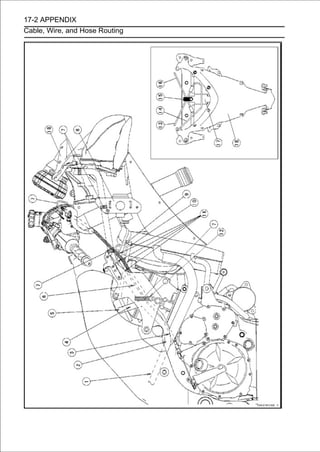
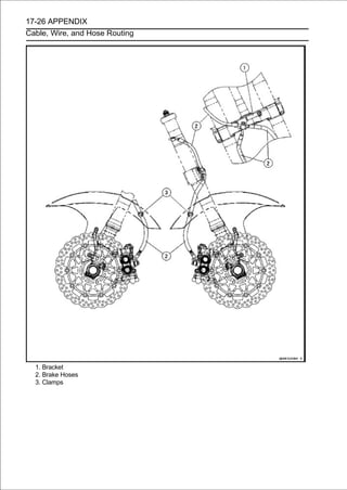
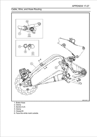
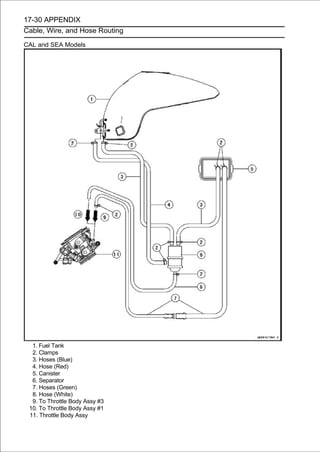
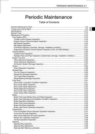
![1-12 GENERAL INFORMATION
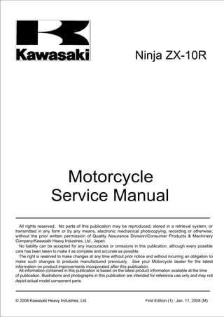
Technical Information-KIMS (Kawasaki Ignition Management System)
Overview
This motorcycle is equipped with the Kawasaki ignition management system which was developed
as a rider aid for track riding using technology borrowed from racing machines. Experienced racers
or track riders can deliberately cause wheel spin to occur when exiting mid/high speed corners. How-
ever, they rely on precise throttle control to maintain the optimum acceleration level without sacrificing
too much wheel spin. KIMS was designed to aid such riding where precise throttle control is required.
This system has not been developed to eliminate all wheel spin, as there are times when this can
be advantageous for experienced riders, and too much control would lead to a very sterile riding ex-
perience.
Operation
In addition to normal DFI activity the ECU’s
complex programme monitors throttle opening,
vehicle speed, gear position, and the rate of
change of engine speed.
When the ECU detects the rear wheel is
slipping by a sudden change in engine speed,
the previously mentioned factors are calcu-
lated and within certain parameters the ignition
timing is retarded to reduce excessive engine
speed. The number of degrees that the ECU
retards the ignition is determined by continu-
ous sampling, with the aim being to optimize
the relationship between throttle opening, en-
gine/vehicle speed and ultimately ensuring the
optimum combination of grip/acceleration.
To ensure that this system does not act unnecessarily, the following situations are taken into ac-
count.
1. This system does not act at idle speed, small throttle openings, or at full throttle.
2. In cases of snapping open the throttle with the
clutch half-engaged (example [A]), the system
compares the gear position, engine speed
and the vehicle speed to determine whether
or not to engage. This system does not act
when the clutch is at the partially disengaged
or slipping.
3. This system does not act on sudden throttle openings.](https://image.slidesharecdn.com/2008-100321201635-phpapp01/85/2008-23-320.jpg)

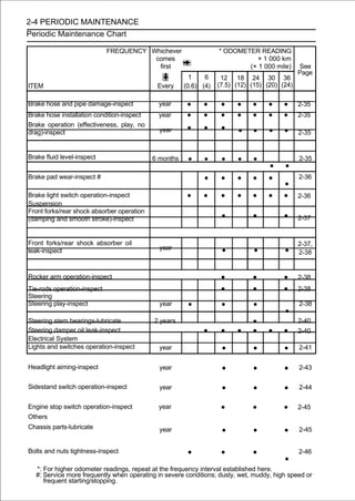
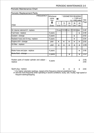
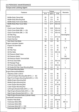
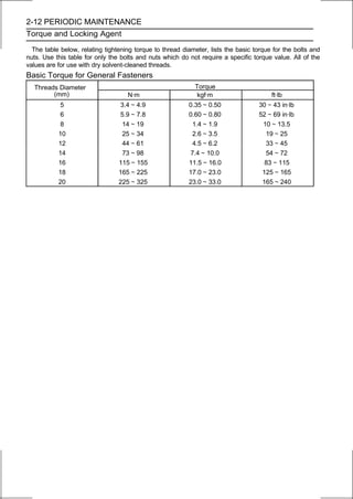
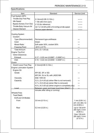
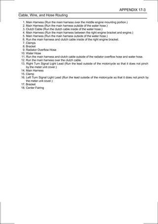
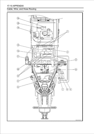
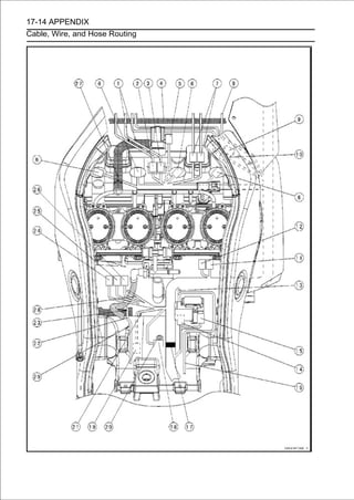
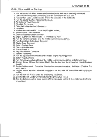
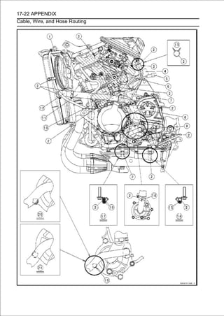
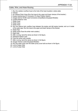
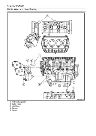
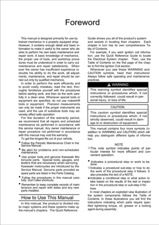
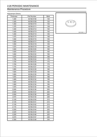
![2-16 PERIODIC MAINTENANCE
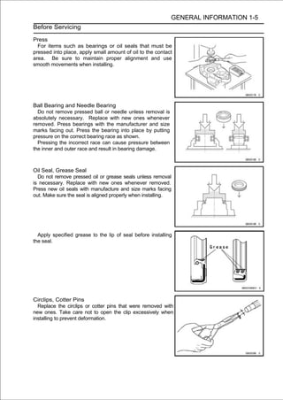
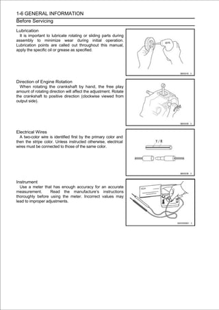
Maintenance Procedure
Fuel System (DFI)
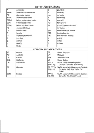
Throttle Control System Inspection
•Check the throttle grip free play [A].
If the free play is incorrect, adjust the throttle cables.
Throttle Grip Free Play
Standard: 2∼3mm(0.08∼0.12in.)
• Checkclose, the throttle grip closes quickly and com- full
open to
that
and the throttle
[B] moves smoothly from
pletely by the return spring in all steering positions.
If the throttle grip does not return properly, check the throttle
cables routing, grip free play, and cable damage. Then
lubricate the throttle cable.
• Run the engine at the idle speed, and turn the handlebar
all the way to the right and left to ensure that the idle speed
does not change.
If the idle speed increases, check the throttle cable free
play and the cable routing.
If necessary, adjust the throttle cable as follows.
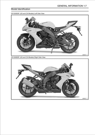
• Loosen the locknuts [A] [B].
• Screw both throttle cable adjusters [C] [D] to give the
throttle grip plenty of play.
• Turn the decelerator cable adjuster [C] until 2
∼ 0.12 in.) of throttle grip play is obtained.
∼ 3 mm (0.08
• Tighten the locknut [A].
• Turn the accelerator cable adjuster [D] until 2
∼ 0.12 in.) of throttle grip play is obtained.
∼ 3 mm (0.08
• Tighten the locknut [B].
If the free play can not be adjusted with the adjusters,
replace the cable.
Engine Vacuum Synchronization Inspection
NOTE
○These procedures are explained on the assumption that
the inlet and exhaust systems of the engine are good
condition.
• Situate the motorcycle so that it is vertical.
• Remove:
Air Cleaner Housing (see Air Cleaner Housing Removal
in the Fuel System (DFI) chapter)
Primary Fuel Hose (see Fuel Hose Replacement)
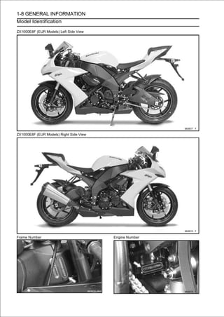
• Plug the breather hose end [A] and air switching valve
hose end [B].](https://image.slidesharecdn.com/2008-100321201635-phpapp01/85/2008-42-320.jpg)
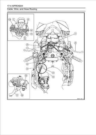
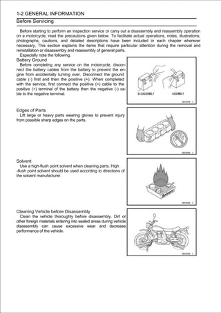
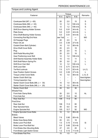
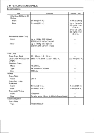
![PERIODIC MAINTENANCE 2-17
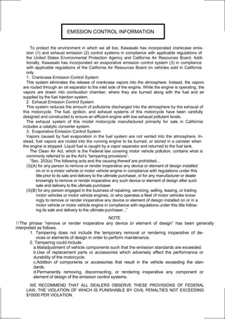
Maintenance Procedure
• Remove the rubber caps [A] from the fittings of each throt-
tle body
• For the California and Southeast Asia models, pull off the
vacuum hoses [B].
• Connect atovacuum gaugethe throttle body. (Special Tool:
57001-1369) the fittings on
and hoses [A]
Special Tool - Vacuum Gauge: 57001-1369
• Connect a highly accurate tachometer [B] to one of the
stick coil primary leads.
• Connect the Lead Connector [A]
Fuel Pump
following parts temporarily.
Extension Tube [B]
Special Tool - Extension Tube: 57001-1578
• Connect the following parts temporarily.
Inlet Air Temperature Sensor Connector [A]
Secondary Fuel Hose [B] (see Fuel Hose Replacement)
NOTE
○Be sure to connect the air temperature sensor connec-
tor. When the ignition switch is turned ON with inlet air
temperature sensor connector disconnected, the ECU
detects the service code 13. Then the ECU starts the
fail-safe (see Self-diagnosis Outline in the Fuel System
(DFI) chapter). In this case, the engine vacuum syn-
chronization can not be inspected correctly.
○Do not connect the secondary fuel injector connectors.
The engine vacuum synchronization is inspected with
the air cleaner housing removed and the engine started.
The secondary fuel injectors are operating with following
conditions.
1. The engine speed is more than 6 000 r/min (rpm).
2. The throttle opening is more than 30°.
WARNING
Gasoline is extremely flammable and can be explo-
sive under certain condition. Especially, the gaso-
line jetted from the secondary fuel injector is ex-
tremely flammable for atomizing the gasoline by the
injector.](https://image.slidesharecdn.com/2008-100321201635-phpapp01/85/2008-43-320.jpg)
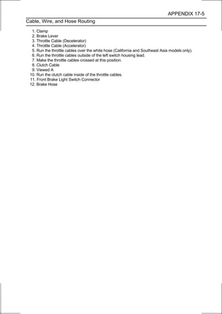
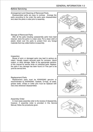
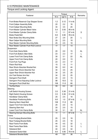
![2-18 PERIODIC MAINTENANCE
Maintenance Procedure
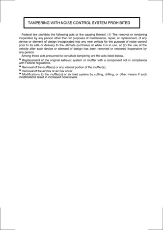
• Start the engine and warm it up thoroughly.
• Check the idle speed, using a highly accurate tachometer
[A].
Idle Speed
Standard: 1 100 ±50 r/min (rpm)
If the idle speed is out of the specified range, adjust it with the
adjusting screw (see Idle Speed Adjustment).
CAUTION
Do not measure the idle speed by the tachometer of
the meter unit.
• While idling thegauge [B].inspect the throttle body vacuum,
using the vacuum
engine,
Throttle Body Vacuum
Standard: 32.7 ±1.33 kPa (245 ± 10 mmHg) at idle
speed
If any vacuum is not within specifications, first
synchronize the balance of the left (#1, #2 throttle valves)
and right (#3, #4 throttle valves) assemblies.
Example:
#1: 220 mmHg
#2: 250 mmHg
#3: 210 mmHg
#4: 230 mmHg
• With the engine at the correct idle speed, equalize higher
vacuum of #1 or #2 (for example 250 mmHg) to higher
vacuum of #3 or #4 (for example 230 mmHg) by turning
the center adjusting screw [A].
Rear View [B]
NOTE
○After adjustment, the final vacuum measurement be-
tween the highest throttle valves may not be 250 mmHg
(for example). The goal is to have the highest two vac-
uums between the left (#1 and #2) and right (#3 and #4)
banks be the same.
• Open and close the necessary. each measurement, and
adjust the idle speed as
throttle after
NOTE
○The engine vacuum synchronization is adjusted with
the secondary fuel injector connectors disconnected.
Therefore, the secondary fuel injectors do not operate
while adjusting the engine vacuum synchronization. If
raising the engine speed more than 6 000 r/min (rpm),
the engine may not operate smoothly.
• Once the throttle main throttle sensorsynchronized, inspect
output voltage of the
valves have been
to ensure proper
operation (procedure is explained at the end of this sec-
tion).](https://image.slidesharecdn.com/2008-100321201635-phpapp01/85/2008-44-320.jpg)
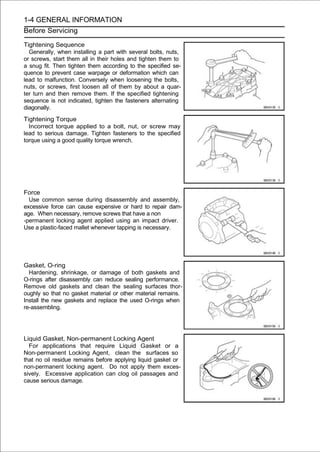
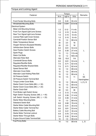
![PERIODIC MAINTENANCE 2-19
Maintenance Procedure
If any one vacuum measurement is out of the specified
range after left (#1, #2) and right (#2, #3) synchroniza-
tion, adjust the bypass screws [A] Using the pilot screw
adjuster [B].
Front View [C]
Special Tool - Pilot Screw Adjuster, D: 57001-1588
• vacuumthe lower vacuum between #1 and #2 to the higher
Adjust
of #1 and #2.
• vacuumthe lower vacuum between #3 and #4 to the higher
Adjust
of #3 and #4.
• ment, and adjust the idle speed as necessary. measure-
Open and close the throttle valves after each
NOTE
○The engine vacuum synchronization is adjusted with the
secondary injector connectors disconnected. There-
fore, the secondary injectors do not operate while ad-
justing the engine vacuum synchronization. If raising
the engine speed more than 6 000 r/min (rpm), the
engine may not operate smoothly.
• Check the vacuums as before.
If all vacuums are within the specification range, finish the
engine vacuum synchronization.
If any vacuum can not be adjusted within the specification,
remove the bypass screws #1 ∼ #4 and replace them with
new ones.
• Turn in the bypass screw [A] with counting the number of
turns until it seals fully but not tightly. Record the number of
turns.
• Remove:
Bypass Screw
Spring [B]
Washer [C]
O-ring [D]
• Check the bypass screw hole in the throttle body for car-
bon deposits.
If any carbons accumulate, wipe the carbons off from the
hole, using a cotton pad penetrated with a high-flash point
solvent.
• Replace the bypass screw, spring, washer and O-ring as
a set.
• Turn in the bypass screw until it seats fully but not tightly.
CAUTION
Do not over-tighten the bypass screw. The tapered
portion [E] of the bypass screw could be damaged.](https://image.slidesharecdn.com/2008-100321201635-phpapp01/85/2008-45-320.jpg)
![2-20 PERIODIC MAINTENANCE
Maintenance Procedure
• Backin. This is same the screwoftoturns counted when first
turned
out the
to set
number
its original position.
NOTE
○A throttle body has different “turns out” of the bypass
screw for each individual unit. On setting the bypass
screw, use the “turns out” determined during disassem-
bly.
• Repeat the same procedure for other bypass screws.
• Repeat the synchronization.
If the vacuums are correct, check the output voltage of
the main throttle sensor (see Main Throttle Sensor Output
Voltage Inspection in the Fuel System (DFI) chapter).
Special Tool - Throttle Sensor Setting Adapter: 57001
-1538
Main Throttle Sensor Output Voltage
Connections to Adapter:
Digital Meter (+) → R (sensor Y/W) lead
Digital Meter (-) → BK (sensor BR/BK) lead
Standard: DC 0.645 ∼ 0.675 V at idle throttle opening
If the output voltage is out of the standard, check the in-
put voltage of the main throttle sensor (see Main Throttle
Sensor Input Voltage Inspection in the Fuel System (DFI)
chapter).
• Remove the vacuum gauge hoses and install the rubber
caps on the original position.
• For the California and Southeast Asia models, install the
vacuum hoses.
○Run the vacuum hoses according to Cable, Wire, and
Hose Routing section in the Appendix chapter. Refer to
the diagram of the evaporative emission control system
in the Fuel System (DFI) chapter too.
Idle Speed Inspection
• Start the engine and warm it up thoroughly.
• With the engine idling, turn the handlebar to both sides
[A].
If handlebar movement changes the idle speed, the
throttle cables may be improperly adjusted or incorrectly
routed, or damaged. Be sure to correct any of these
conditions before riding (see Cable, Wire, and Hose
Routing section in the Appendix chapter).
WARNING
Operation with improperly adjusted, incorrectly
routed, or damaged cables could result in an
unsafe riding condition.
• Check the idle speed.
If the idle speed is out of specified range, adjust it.
Idle Speed
Standard: 1 100 ±50 r/min (rpm)](https://image.slidesharecdn.com/2008-100321201635-phpapp01/85/2008-46-320.jpg)
![PERIODIC MAINTENANCE 2-21
Maintenance Procedure
Idle Speed Adjustment
• Start the engine and warm it up thoroughly.
• Turn the adjusting screw [A] until the idle speed is correct.
○Open and close the throttle a few times to make sure that
the idle speed is within the specified range. Readjust if
necessary.
Fuel Hose Inspection (fuel leak, damage,
installation condition)
○If the motorcycle is not properly handled, the high pres-
sure inside the fuel line can cause fuel to leak [A] or the
hose to burst. Remove the fuel tank (see Fuel Tank Re-
moval in the Fuel System (DFI) chapter) and check the
fuel hoses.
Replace the fuel hose if any fraying, cracks [B] or bulges
[C] are noticed.
• Check thatand Hose Routing[A] are routed Appendix to
Cable, Wire,
the fuel hoses
section in the
according
chapter.
Replace the hose if it has been sharply bent or kinked.
• Push and pull [A]fuel fuel hose joint [B]securely connected.
○
Check that the
the
hose joints are
back and forth
more than two times, and make sure it is locked.
○Check the other hose joint in the same way.
CAUTION
When pushing and pulling the fuel hose joint, do
not apply strong force to the delivery pipe [C] on
the nozzle assy. The pipe made from resin could be
damaged.
WARNING
Make sure the hose joint is installed correctly on the
delivery pipe by sliding the joint, or the fuel could
leak.
If it does not locked, reinstall the hose joint.](https://image.slidesharecdn.com/2008-100321201635-phpapp01/85/2008-47-320.jpg)
![2-22 PERIODIC MAINTENANCE
Maintenance Procedure
Evaporative Emission Control System Inspection
(CAL and SEA Models)
• Inspect the canister as follows.
○Remove the left upper inner fairing (see Upper Inner Fairing
Removal in the Frame chapter).
○Remove the canister [A], and disconnect the hoses from
the canister.
○Visually inspect the canister for cracks or other damage. If
the canister has any cracks or bad damage, replace it with a
new one.
NOTE
○The canister is designed to work well through the
motorcycle’s life without any maintenance if it is used under
normal conditions.
• Check the liquid/vapor separator as follows.
○Remove the upper fairing assembly (see Upper Fairing
Assembly Removal in the Frame chapter).
○Disconnect the hoses from the separator, and remove the
separator [A] from the motorcycle left side.
○Visually inspect the separator for cracks and other dam-
age.
If the separator has any cracks or damage, replace it with a
new one.
○To prevent the gasoline from flowing into or out of the
canister, hold the separator perpendicular to the ground.
• Check the hoses of the evaporative emission control system
as follows.
○Check that the hoses are securely connected and clips
are in position.
○Replace any kinked, deteriorated or damaged hoses.
○Route the hoses according to Cable, Wire, and Hose
Routing section in the Appendix chapter.
○When installing the hoses, avoid sharp bending, kinking,
flattening or twisting, and route the hoses with a minimum
of bending so that the emission flow will not be obstructed.](https://image.slidesharecdn.com/2008-100321201635-phpapp01/85/2008-48-320.jpg)
![PERIODIC MAINTENANCE 2-23
Maintenance Procedure
Cooling System
Coolant Level Inspection
NOTE
○Check the level when the engine is cold (room or ambient
temperature).
• Check the coolant level in the reserve tank [A] with the
motorcycle held perpendicular (Do not use the sidestand).
If the coolant level is lower than the “L” level line [B], re-
move the left upper fairing cover (see Upper Fairing Cover
Removal in the Frame chapter), and then unscrew the re-
serve tank cap and add coolant to the “F” level line [C].
“L”: Low
“F”: Full
CAUTION
For refilling, add the specified mixture of coolant
and soft water. Adding water alone dilutes the
coolant and degrades its anticorrosion properties.
The diluted coolant can attack the aluminum en-
gine parts. In an emergency, soft water alone can
be added. But the diluted coolant must be returned
to the correct mixture ratio within a few days.
If coolant must be added often or the reservoir tank
has run completely dry, there is probably leakage in
the cooling system. Check the system for leaks.
Coolant ruins painted surfaces. Immediately wash
away any coolant that spills on the frame, engine,
wheels or other painted parts.
Radiator Hose and Pipe Inspection (coolant leak,
damage, installation condition)
○The high pressure inside the radiator hose can cause
coolant to leak [A] or the hose to burst if the line is not
properly maintained. Visually inspect the hoses for signs
of deterioration. Squeeze the hoses. A hose should not
be hard and brittle, nor should it be soft or swollen.
Replace the hose if any fraying, cracks [B] or bulges [C]
are noticed.
• Check that the hoses are securely connected and clamps
are tightened correctly.
Torque - Radiator (Water) Hose Clamp Screws: 2.0 N·m
(0.20 kgf·m, 18 in·lb)](https://image.slidesharecdn.com/2008-100321201635-phpapp01/85/2008-49-320.jpg)
![2-24 PERIODIC MAINTENANCE
Maintenance Procedure
Engine Top End
Valve Clearance Inspection
NOTE
○Valve clearance must be checked and adjusted when
the engine is cold (at room temperature).
• Remove theincylinder head coverchapter).
Cover Removal the Engine Top End
(see Cylinder Head
• Remove on the starter clutch cover [C]. and starter clutch
bolt cap [B]
the timing inspection cap [A]
• Using aclockwiseon the starter clutch mark[A], #1,4 the
crankshaft
wrench
until the line [B] (TDC
bolt
for
turn
pistons) on the starter clutch is aligned with the notch [C] in
the edge of the timing inspection hole [D] in the starter
clutch cover.
• Using thethickness gauge [A],lifter.
between
a
cam and the valve
measure the valve clearance
Valve Clearance
Standard:
Exhaust 0.17 ∼ 0.22 mm (0.0067 ∼ 0.0087 in.)
Inlet 0.15 ∼ 0.22 mm (0.0059 ∼ 0.0087 in.)
NOTE
○Thickness gauge is horizontally inserted on the valve
lifter.
Appropriateness [A]
Inadequacy [B]
Thickness Gauge [C]
Horizontally Inserts [D]
Cam [E]
Valve Lifter [F]
Hits the Valve Lifter Ahead [G]](https://image.slidesharecdn.com/2008-100321201635-phpapp01/85/2008-50-320.jpg)
![PERIODIC MAINTENANCE 2-25
Maintenance Procedure
○When positioning #1 piston TDC at the end of the
compression stroke:
Inlet Valve Clearance of #1 and #3 Cylinders
Exhaust Valve Clearance of #1 and #2 Cylinders
Measuring Valve [A]
○When positioning #4 piston TDC at the end of the
compression stroke:
Inlet Valve Clearance of #2 and #4 Cylinders
Exhaust Valve Clearance of #3 and #4 Cylinders
Measuring Valve [A]
If the valve clearance is not within the specified range,
first record the clearance, and then adjust it.
Valve Clearance Adjustment
• To change the valve clearance, remove the camshafts
(see Camshaft Removal in the Engine Top End chapter)
and valve lifters.
• Replace the shim with one of a different thickness.
NOTE
○Mark and record the locations of the valve lifters and
shims so that they can be reinstalled in their original
positions.
• Clean the shim to remove any dust or oil.
• Measure the thickness of the removed shim [A].
• Select a new shim thickness calculation as follows.
a+b-c=d
[a] Present Shim Thickness
[b] Measured Valve Clearance
[c] Specified Valve Clearance (Mean Value = 0.195 mm
(Exhaust), 0.185 mm (Inlet))
[d] Replace Shim Thickness
Example (Exhaust):
1.600 + 0.31 - 0.195 = 1.715 mm
○Exchange the shim for the 1.725 size shim.](https://image.slidesharecdn.com/2008-100321201635-phpapp01/85/2008-51-320.jpg)
![PERIODIC MAINTENANCE 2-27
Maintenance Procedure
CAUTION
Be sure to remeasure the clearance after selecting a
shim. The clearance can be out of the specified
range because of the shim tolerance.
○If there is no valve clearance, use a shim that is a few
sizes smaller, and remeasure the valve clearance.
• When installing the shim, face the marked side toward the
valve lifter. At this time, apply engine oil to the shim or
the valve lifter to keep the shim in place during camshaft
installation.
CAUTION
Do not put shim stock under the shim. This may
cause the shim to pop out at high rpm, causing
extensive engine damage.
Do not grind the shim. This may cause it to fracture,
causing extensive engine damage.
• Applyand install the lifter. oil solution to the valve lifter
surface
molybdenum disulfide
• Install the camshafts (see Camshaft Installation in the Engine
Top End chapter).
• Recheck the valve clearance and readjust if necessary.
• Install the removed parts (see appropriate chapters).
Air Suction System Damage Inspection
• Remove:
Middle Air Cleaner Housing (see Air Cleaner Housing
Removal in the Fuel System (DFI) chapter)
Primary Fuel Hose (see Fuel Hose Replacement)
• Separate the air switching valve hose [A] from the lower air
cleaner housing.
• Connect the Lead Connector [A]
Fuel Pump
following parts temporarily.
Extension Tube [B]
Special Tool - Extension Tube: 57001-1578](https://image.slidesharecdn.com/2008-100321201635-phpapp01/85/2008-53-320.jpg)
![2-28 PERIODIC MAINTENANCE
Maintenance Procedure
• Connect the following parts temporarily.
Inlet Air Temperature Sensor Connector [A]
Secondary Fuel Hose [B] (see Fuel Hose Replacement)
NOTE
○When the ignition switch is turned ON with inlet air tem-
perature sensor connector disconnected, the ECU de-
tects the service code 13 (see Self-diagnosis Outline in
the Fuel System (DFI) chapter).
○Do not connect the secondary fuel injector connectors.
The air suction system is inspected with the middle air
cleaner housing removed and the engine started. The
secondary fuel injectors are operating with following
conditions.
1. The engine speed is more than 6 000 r/min (rpm).
2. The throttle opening is more than 30°
WARNING
Gasoline is extremely flammable and can be explo-
sive under certain condition. Especially, the gaso-
line jetted from the secondary fuel injector is ex-
tremely flammable for atomizing the gasoline by the
injector.
• Start the engine and run it at idle speed.
• Plug the air switching in the hose. end [A] with your finger
and feel vacuum pulsing
valve hose
If there is no vacuum pulsation, check the hose line for
leak. If there is no leak, check the air switching valve
(see Air Switching Valve Unit Test in the Electrical System
chapter) or air suction valve (see Air Suction Valve
Inspection in the Engine Top End chapter).
Clutch
Clutch Operation Inspection
•
[A].
Pull the clutch lever just enough to take up the free play
• Measure the gap between the lever and the lever holder.
If the gap is too wide, the clutch may not release fully. If
the gap is too narrow, the clutch may not engage fully. In
either case, adjust it.
Clutch Lever Free Play
Standard: 2∼3mm(0.08∼0.12in.)](https://image.slidesharecdn.com/2008-100321201635-phpapp01/85/2008-54-320.jpg)
![PERIODIC MAINTENANCE 2-29
Maintenance Procedure
WARNING
To avoid a serious burn, never touch the engine or
exhaust pipe during clutch adjustment.
• visible.the adjuster [A] so that 4 ∼ 6 mm (0.16 ∼ 0.24 in.) [B] of threads
is Turn
• Slide the dust cover [A] at the clutch cable lower end out of
place.
• Loosen both far as theynuts go. at the bracket [C] on the
clutch cover as
adjusting
will
[B]
• Pull the clutchbracket. [D] tight and tighten the adjusting
nuts against the
outer cable
• Slip the rubber dust cover back onto place.
• Turn the adjuster at the clutch lever until the free play is
correct.
• Push the release leverhard totoward
motorcycle until it becomes
[A]
turn.
the front of the
○At this time, the release lever should have the proper angle
shown.
60° [B]
If the angle is wrong, check the clutch and release parts
for wear.
WARNING
Be sure that the outer cable end at the clutch lever is
fully seated in the adjuster at the clutch lever, or it
could slip into place later, creating enough cable play
to prevent clutch disengagement.
• Afterdoes not slip and that it the engine and check that the
clutch
the adjustment, start
releases properly.
Wheels/Tires
Tire Air Pressure Inspection
• Measure the tire air pressure with an air pressure gauge
[A] when the tires are cold (that is, when the motorcycle
has not been ridden more than a mile during the past 3
hours).
• Install the air valve cap.
Adjust the tire air pressure according to the specifications
if necessary.
Air Pressure (when Cold)
Front: Up to 180 kg (397 lb)
250 kPa (2.5 kgf/cm², 36 psi)
Rear: Up to 180 kg (397 lb)
290 kPa (2.9 kgf/cm², 42 psi)](https://image.slidesharecdn.com/2008-100321201635-phpapp01/85/2008-55-320.jpg)
![2-30 PERIODIC MAINTENANCE
Maintenance Procedure
Wheel/Tire Damage Inspection
• Remove any imbedded stones [A] or other foreign
particles [B] from tread.
• Visually inspect the tire for cracks and cuts, and replace
the tire if necessary. Swelling or high spots indicate inter-
nal damage, requiring tire replacement.
• Visually inspect the wheel for cracks, cuts and dents dam-
age.
If any damage is found, replace the wheel if necessary.
Tire Tread Wear Inspection
As the tire tread wears down, the tire becomes more
susceptible to puncture and failure. An accepted estimate is
that 90% of all tire failures occur during the last 10% of tread life
(90% worn). So it is false economy and unsafe to use the
tires until they are bald.
• Measure the tread depth at the center of the tread with a
depth gauge [A]. Since the tire may wear unevenly, take
measurement at several places.
If any measurement is less than the service limit, replace
the tire (see Tire Removal/Installation in the Wheels/Tires
chapter).
Tread Depth
Standard:
EUR and CA Models:
Front 3.8 mm (0.15 in.)
Rear 5.2 mm (0.20 in.)
Other than EUR and CA Models:
Front 3.6 mm (0.14 in.)
Rear 5.3 mm (0.21 in.)
Service Limit:
Front 1 mm (0.04 in.)
(AT, CH, DE) 1.6 mm (0.06 in.)
Rear 2 mm (0.08 in.) (Up to 130 km/h)
3 mm (0.12 in.) (Over 130 km/h)
WARNING
To ensure safe handling and stability, use only the
recommended standard tires for replacement,
inflated to the standard pressure.
NOTE
○Most countries may have their own regulations a mini-
mum tire tread depth: be sure to follow them.
○Check and balance the wheel when a tire is replaced
with a new one.](https://image.slidesharecdn.com/2008-100321201635-phpapp01/85/2008-56-320.jpg)
![PERIODIC MAINTENANCE 2-31
Maintenance Procedure
Wheel Bearing Damage Inspection
• Raise the front wheel off the ground with the jack (see
Front Wheel Removal in the Wheels/Tires chapter).
Special Tool - Jack: 57001-1238
Jack Attachment: 57001-1608
• Turn the handlebar all the way to the right or left.
• Inspect thewith both hands to front sides. bearing by moving
[A] the wheel
roughness of the
both
wheel
• Spin [B] the front wheelnoise. and check for smoothly
turn, roughness, binding or
lightly,
If roughness, binding or noise is found, remove the front
wheel and inspect the wheel bearing (see Front Wheel
Removal, Hub Bearing Inspection in the Wheels/Tires
chapter).
• Raise theRemoval in the Wheels/Tireswith the stand (see
Rear Wheel
rear wheel off the ground
chapter).
• Spin [A] the rear wheelnoise. and check for smoothly
turn, roughness, binding or
lightly,
If roughness, binding or noise is found, remove the rear
wheel and inspect the wheel bearing (see Rear Wheel Re-
moval, Hub Bearing Inspection in the Wheels/Tires chap-
ter) and coupling (see Coupling Bearing Inspection in the
Final Drive chapter).
Final Drive
Drive Chain Lubrication Condition Inspection
• If a special lubricant is not available, a heavy oil such as
SAE 90 is preferred to a lighter oil because it will stay on
the chain longer and provide better lubrication.
• If the chain appears especially dirty, clean it before lubri-
cation.
CAUTION
The O-rings between the side plates seal in the
lubricant between the pin and the bushing. To avoid
damaging the O-rings and resultant loss of
lubricant, observe the following rules.
Use only kerosene or diesel oil for cleaning of the
O-ring of the drive chain.
Any other cleaning solution such as gasoline or
trichloroethylene will cause deterioration and
swelling of the O-ring.
Immediately blow the chain dry with compressed air
after cleaning.
Complete cleaning and drying the chain within 10
minutes.](https://image.slidesharecdn.com/2008-100321201635-phpapp01/85/2008-57-320.jpg)
![2-32 PERIODIC MAINTENANCE
Maintenance Procedure
• Apply oil to thebushings. the rollersoil tothat oil will penetrate
to the rollers and
sides of
Apply the
so
the O-rings so
that the O-rings will be coated with oil.
• Wipe off any excess oil.
Oil Applied Areas [A]
O-rings [B]
Drive Chain Slack Inspection
NOTE
○Check the slack with the motorcycle setting on its side
stand.
○Clean the chain if it is dirty, and lubricate it if it appears
dry.
• Check the wheel alignment (see Wheel Alignment Inspec-
tion).
• Rotate the rear wheel to find the position where the chain is
tightest.
• Measure the vertical movement (chain slack) [A] midway
between the sprockets.
If the chain slack exceeds the standard, adjust it.
Chain Slack
Standard: 30 ∼ 40 mm (1.2 ∼ 1.6 in.)
Drive Chain Slack Adjustment
• Remove the cotter pin [A], and loosen the rear axle nut
[B].
• Loosen the both chain adjuster locknuts [C].
If the chain is too loose, turn out the left and right chain
adjusters [D] evenly.
If the chain is too tight, turn in the left and right chain
adjusters evenly, and kick the wheel forward.
• Turn the left and right chain adjusters evenly until the
drive chain has the correct amount of slack. To keep
the chain and wheel properly aligned, the notch [E] on the
left wheel alignment indicator [F] should align with the same
swingarm mark or position [G] that the right indicator notch
aligns with.
WARNING
Misalignment of the wheel will result in abnormal
wear and may result in an unsafe riding condition.
• Tighten the both chain adjuster locknuts securely.
• Tighten the rear axle nut.
Torque - Rear Axle Nut: 108 N·m (11.0 kgf·m, 80 ft·lb)
• Turn the wheel, measure the chain slack again at the tightest
position, and readjust if necessary.](https://image.slidesharecdn.com/2008-100321201635-phpapp01/85/2008-58-320.jpg)
![PERIODIC MAINTENANCE 2-33
Maintenance Procedure
• Insert a new cotter pin [A].
NOTE
○When inserting the cotter pin, if the slots in the nut do
not align with the cotter pin hole in the axle, tighten the nut
clockwise [B] up to next alignment.
○It should be within 30 degree.
○Loosen once and tighten again when the slot goes past the
nearest hole.
• Bend the cotter pin [A] over the nut [B].
WARNING
If the rear axle nut is not securely tightened or the
cotter pin is not installed, an unsafe riding condition
may result.
Wheel Alignment Inspection
• Check that the notch [A] on the left alignment indicator [B]
aligns with the same swingarm mark or position [C] that
the right alignment indicator notch aligns with.
If they do not, adjust the chain slack and align the wheel
alignment (see Drive Chain Slack Adjustment).
NOTE
○Wheel alignment can be also checked using the
straightedge or string method.
WARNING
Misalignment of the wheel will result in abnormal
wear, and may result in an unsafe riding condition.
Drive Chain Wear Inspection
• Remove the chain cover (see Drive Chain Removal in the
Final Drive chapter).
• Rotate the rear wheel to inspect the drive chain for
damaged rollers, and loose pins and links.
If there is any irregularity, replace the drive chain.
Lubricate the drive chain if it appears dry.
• Stretch the chain taut by hanging a 98 N (10 kg, 20 lb)
weight [A] on the chain.
• Measure the length of 20 links [B] on the straight part [C] of
the chain from the pin center of the 1st pin to the pin center
of the 21st pin. Since the chain may wear unevenly, take
measurements at several places.
If any measurements exceed the service limit, replace the
chain. Also, replace the front and rear sprockets when the
drive chain is replaced.
Drive Chain 20-link Length
Standard: 317.5 ∼ 318.2 mm (12.50 ∼ 12.53 in.)
Service Limit: 323 mm (12.7 in.)](https://image.slidesharecdn.com/2008-100321201635-phpapp01/85/2008-59-320.jpg)
![2-34 PERIODIC MAINTENANCE
Maintenance Procedure
WARNING
If the drive chain wear exceeds the service limit,
replace the chain or an unsafe riding condition may
result. A chain that breaks or jumps off the sprockets
could snag on the engine sprocket or lock the rear
wheel, severely damaging the motorcycle and
causing it to go out of control.
For safety, use only the standard chain. It is an end-
less type and should not be cut for installation.
Standard Chain
Make: RK EXCEL
Type: RK 525MFOZ, Endless
Link: 110 links
Chain Guide Wear Inspection
•Visually inspect the chain guide [A].
Replace the chain guide if it shows any signs of abnormal
wear or damage.
Brake
Brake Fluid Leak (Brake Hose and Pipe) Inspection
• Apply the brake lever or pedal and inspect the brake fluid
leak from the brake hoses [A] and fittings [B].
If the brake fluid leaked from any position, inspect or
replace the problem part.](https://image.slidesharecdn.com/2008-100321201635-phpapp01/85/2008-60-320.jpg)
![PERIODIC MAINTENANCE 2-35
Maintenance Procedure
Brake Hose Damage and Installation Condition
Inspection
• Inspect the brake hoses and fittings for deterioration,
cracks and signs of leakage.
○The high pressure inside the brake line can cause fluid to
leak [A] or the hose to burst if the line is not properly main-
tained. Bend and twist the rubber hose while examining
it.
Replace the hose if any crack [B], bulge [C] or leakage is
noticed.
Tighten any brake hose banjo bolts.
Torque - Brake Hose Banjo Bolts: 25 N·m (2.5 kgf·m, 18
ft·lb)
• Inspect the brake hose routing.
If any brake hose routing is incorrect, route the brake hose
according to Cable, Wire, and Hose Routing section in the
Appendix chapter.
Brake Operation Inspection
• Inspect the operation of the front and rear brake by
running the vehicle on the dry road.
If the brake operation is insufficiency, inspect the brake
system.
WARNING
When inspecting by running the vehicle, note a
surrounding traffic situation enough in the place of
safety.
Brake Fluid Level Inspection
• Check that the brake fluid level in the front brake reservoir [A]
is above the lower level line [B].
NOTE
○Hold the reservoir horizontal by turning the handlebar
when checking brake fluid level.
If the fluid level is lower than the lower level line, fill the
reservoir to the upper level line [C].
○Remove the stopper [D].
• Check the lowerbrake fluid level in the rear brake reservoir [A]
is above
that the
level [B].
If the fluid level is lower than the lower level line, fill the
reservoir to the upper level line [C].
○Remove the stopper [D].
WARNING
Change the brake fluid in the brake line completely
if the brake fluid must be refilled but the type and
brand of the brake fluid that is already in the reser-
voir are unidentified. After changing the fluid, use
only the same type and brand of fluid thereafter.
Recommended Disc Brake Fluid
Grade: DOT4](https://image.slidesharecdn.com/2008-100321201635-phpapp01/85/2008-61-320.jpg)
![2-36 PERIODIC MAINTENANCE
Maintenance Procedure
• Follow the cap correctly. to install the front/rear brake
fluid reservoir
procedure below
○First, tighten the brake fluid reservoir cap [B] clockwise
[C] by hand until the resistance is felt fully; then, tighten
the cap an additional 1/6 turn [D] while holding the brake
fluid reservoir body [A].
○Tighten:
Torque - Front Brake Reservoir Cap Stopper Screw: 1.2
N·m (0.12 kgf·m, 11 in·lb)
Brake Pad Wear Inspection
• Remove the brake pads (see Front/Rear Brake Pad
Removal in the Brakes chapter).
• Check the lining thickness [A] of the pads in each caliper.
If the lining thickness of either pad is less than the service
limit [B], replace both pads in the caliper as a set.
Front Brake Pad [C]
Rear Brake Pad [D]
Pad Lining Thickness
Standard:
Front 4.0 mm (0.16 in.)
Rear 5.0 mm (0.20 in.)
Service Limit: 1 mm (0.04 in.)
Brake Light Switch Operation Inspection
• Turn the ignition switch ON.
• The brake light [A] should go on when the brake lever is
applied or after the brake pedal is depressed about 10
mm (0.39 in.).
If it does not, adjust the brake light switch.
• While holding the switch body, turn the adjusting nut to
adjust the switch.
Switch Body [A]
Adjusting Nut [B]
Light sooner as the body rises [C]
Light later as the body lowers [D]
CAUTION
To avoid damaging the electrical connections
inside the switch, be sure that the switch body does
not turn during adjustment.](https://image.slidesharecdn.com/2008-100321201635-phpapp01/85/2008-62-320.jpg)
![PERIODIC MAINTENANCE 2-37
Maintenance Procedure
If it does not go on, inspect or replace the following parts.
Battery (see Charging Condition Inspection in the Electrical
System chapter)
Brake Light (see Tail/Brake Light Removal in the Electrical
System chapter)
Main Fuse 30 A and Taillight Fuse 10 A (see Fuse
Inspection in the Electrical System chapter)
Front Brake Light Switch [A] (see Switch Inspection in
the Electrical System chapter)
Rear Brake Light Switch (see Switch Inspection in the
Electrical System chapter)
Harness (see Wiring Inspection in the Electrical System
chapter)
Suspensions
Front Forks/Rear Shock Absorber Operation
Inspection
• Pump the forks down and up [A] 4 or 5 times, and inspect the
smooth stroke.
If the forks do not smoothly or noise is found, inspect the
fork oil level or fork clamps (see Front Fork Oil Change in the
Suspension chapter).
• Pumpthe smoothseat down and up [A] 4 or 5 times, and
inspect
the rear
stroke.
If the shock absorber does not smoothly stroke or noise is
found, inspect the oil leak (see Rear Shock Absorber Oil
Leak Inspection).
Front Fork Oil Leak Inspection
• Visually inspect the front forks [A] for oil leakage.
Replace or repair any defective parts, if necessary.](https://image.slidesharecdn.com/2008-100321201635-phpapp01/85/2008-63-320.jpg)
![2-38 PERIODIC MAINTENANCE
Maintenance Procedure
Rear Shock Absorber Oil Leak Inspection
•Visually inspect the shock absorber [A] for oil leakage.
If the oil leakage is found on it, replace the shock absorber
with a new one.
Rocker Arm Operation Inspection
• Pump the seat down and up 4 or 5 times, and inspect the
smooth stroke.
○In this photo [B], the left lower fairing has been removed for
clarity.
If the rocker arm [A] does not smoothly stroke or
noise is found, inspect the fasteners and bearings (see
Tie-Rod/Rocker Arm Bearing, Sleeve Inspection in the
Suspension chapter).
Tie-Rod Operation Inspection
• Pump the seat down and up 4 or 5 times, and inspect the
smooth stroke.
○In this photo [B], the left lower fairing has been removed for
clarity.
If the tie-rod [A] do not smoothly stroke or noise is found,
inspect the fasteners and tie-rod bearings (see Rocker
Tie-Rod/Rocker Arm Bearing, Sleeve Inspection in the
Suspension chapter).
Steering
Steering Play Inspection
• Raise the front wheel off the ground with the jack (see
Front Wheel Removal in the Wheel/Tires chapter).
Special Tools - Jack: 57001-1238
Jack Attachment: 57001-1608
• With the frontthe handlebar. The front wheel should
tap each end of
wheel pointing straight ahead, alternately
swing fully left and right from the force of gravity until the
fork hits the stop.
If the wheel binds or catches before the stop, the steering is
too tight.
• Feel for steering looseness by pushing and pulling [A] the
forks.
If you feel looseness, the steering is too loose.
NOTE
○The cables and wiring will have some effect on the motion
of the fork which must be taken into account.
○Be sure the wires and cables are properly routed.
○The bearings must be in good condition and properly
lubricated in order for any test to be valid.](https://image.slidesharecdn.com/2008-100321201635-phpapp01/85/2008-64-320.jpg)
![PERIODIC MAINTENANCE 2-39
Maintenance Procedure
Steering Play Adjustment
• Remove the steering stem head with the handlebars (see
Handlebar Removal in the Steering chapter).
• Straighten the claws [A] of the lock washer [B].
• Remove:
Steering Stem Locknut [C]
Lock Washer
• [A]. the steering using the steering stem nut wrench
Adjust
Special Tool - Steering Stem Nut Wrench: 57001-1100
If the steering is too tight, loosen the stem nut [B] a fraction of
a turn.
If the steering is too loose, tighten the stem nut a fraction of
a turn.
NOTE
○Turn the stem nut 1/8 turn at time maximum.
• Install the lock washer [A] so that its bent side [B] faces
upward, and engage the bent claws with the grooves of
the steering stem locknut [C].
• Tighten the stem locknut by hand until the lock washer
touches the steering stem nut [D].
• Tighten the stem locknut again until the claws are aligned
with the grooves (ranging from 2nd to 4th) of the stem nut,
and bend the two claws downward [E].
• Install the steering stem head [F].
• Install the washer [G], and tighten the steering stem head
bolt [H].
Torque - Steering Stem Head Bolt: 108 N·m (11.0 kgf·m, 80
ft·lb)
• Tighten:Upper Front Fork Clamp Bolts 20 N·m (2.0 kgf·m,
Torque -
15 ft·lb)
Handlebar Clamp Bolts: 25 N·m (2.5 kgf·m, 18
ft·lb)
WARNING
Do not impede the handlebar turning by routing the
cables, harness and hoses improperly (see Cable,
Wire, and Hose Routing section in the Appendix
chapter).
• Install the plug [I] on the steering stem head bolt.
• Checksteering is stillagain. or loose, repeat the adjust-
If the
the steering
too tight
ment.](https://image.slidesharecdn.com/2008-100321201635-phpapp01/85/2008-65-320.jpg)
![2-40 PERIODIC MAINTENANCE
Maintenance Procedure
Steering Stem Bearing Lubrication
• Remove the steering stem (see Stem, Stem Bearing
Removal in the Steering chapter).
• Using a high-flash point solvent, wash the upper and
lower ball bearings in the cages, and wipe the upper and
lower outer races, which are press-fitted into the frame
head pipe, clean off grease and dirt.
• Visually check the outer races and the ball bearings.
Replace the bearing assemblies if they show wear or
damage.
• Pack the upper and lower ball bearings [A] in the cages
with grease, and apply a light coat of grease to the upper
and lower outer races.
• Install the steering stem (see Stem, Stem Bearing
Installation in the Steering chapter).
• Adjust the steering (see Steering Play Adjustment).
Steering Damper Oil Leak Inspection
• Visually inspect the steering damper [A] for oil leakage.
If the oil leakage is found on it, replace the steering
damper with a new one.](https://image.slidesharecdn.com/2008-100321201635-phpapp01/85/2008-66-320.jpg)
![PERIODIC MAINTENANCE 2-41
Maintenance Procedure
Electrical System
Lights and Switches Operation Inspection
First Step
• Set the gear position in the neutral position.
• Turn the ignition switch ON.
• The following lights should go on according to below table.
City Lights [A] Go on
Taillight [B] Goes on
License Plate Light [C] Goes on
Meter Panel Illumination Light (LED) [D] Goes on
Meter Panel LCD [E] Goes on
Neutral Indicator Light (LED) [F] Goes on
Fuel Level Warning Indicator Light (LED) Goes on
[G] (for 3 seconds)
Oil Pressure Warning Symbol [H] and Blinks (about 3
Warning Indicator Light (LED) [I] seconds after)
If the light does not go on, inspect or replace the following
parts.
Battery (see Charging Condition Inspection in the
Electrical System chapter)
City Light Bulb (see City Light Bulb Replacement in the
Electrical System chapter)
Licence Plate Light Bulb (see Licence Plate Light Bulb
Replacement in the Electrical System chapter)
Meter Panel LCD (see Meter Unit Inspection in the
Electrical System chapter)
Neutral Indicator Light (LED) (see Meter Unit Inspection in
the Electrical System chapter)
Warning Indicator Light (LED) (Oil Pressure Warning)
(see Meter Unit Inspection in the Electrical System chap-
ter)
Meter Panel Illumination Light (LED) (see Meter Unit In-
spection in the Electrical System chapter)
Fuel Level Warning Indicator Light (LED) (see Meter Unit
Inspection in the Electrical System chapter)
ECU (see ECU Power Supply Inspection in the Fuel Sys-
tem (DFI) chapter)
Main Fuse 30 A and Taillight Fuse 10 A (see Fuse
Inspection in the Electrical System chapter)
Ignition Switch (see Switch Inspection in the Electrical
System chapter)
Oil Pressure Switch (see Switch Inspection in the
Electrical System chapter)
Gear Position Switch (see Gear Position Switch Inspection
in the Electrical System chapter)
Harness (see Wiring Inspection in the Electrical System
chapter)
• Turn the ignition switch OFF.
• Theimmobilizer system, warning models equipped with
an
all lights should go off (for
indicator light (LED) will
blinks. Refer to the Immobilizer System (Equipped Mod-
els) section in the Electrical System chapter).
If the light does not go off, replace the ignition switch.](https://image.slidesharecdn.com/2008-100321201635-phpapp01/85/2008-67-320.jpg)
![2-42 PERIODIC MAINTENANCE
Maintenance Procedure
Second Step
• Turn the ignition switch to P (Park) position.
• The city light, taillight and license plate light should go on.
If the light does not go on, inspect or replace the igni-
tion switch (see Switch Inspection in the Electrical System
chapter).
Third Step
• Turn the ignition switch ON.
• Turn the turn signal switch [A] ON (left or right position).
• The lefttoor right turn signalshould flash.(front and rear)
according the switch position
lights [B]
• The flash.signal indicator light (LED) [C] in the meter unit
should
turn
If the each light does not flash, inspect or replace the
following parts.
Turn Signal Light Bulb (see Turn Signal Light Bulb
Replacement in the Electrical System chapter)
Turn Signal Indicator Light (LED) (see Meter Unit Inspection
in the Electrical System chapter)
Turn Signal Relay Fuse 10 A (see Fuse Inspection in the
Electrical System chapter)
Turn Signal Switch (see Switch Inspection in the Electrical
System chapter)
Turn Signal Relay (see Turn Signal Relay Inspection in
the Electrical System chapter)
Harness (see Wiring Inspection in the Electrical System
chapter)
• Push the turn signal switch.
• The turn signal lights and indicator light (LED) should go
off.
If the light does not go off, inspect or replace the following
parts.
Turn Signal Switch (see Switch Inspection in the Electrical
System chapter)
Turn Signal Relay (see Turn Signal Relay Inspection in
the Electrical System chapter)
Fourth Step
•Set the dimmer switch [A] to low beam position.
•Start the engine.
•The low beam headlight should go on.
If the low beam headlight does not go on, inspect or re-
place the following parts.
Headlight Low Beam Bulb (see Headlight Bulb
Replacement in the Electrical System chapter)
Headlight Fuse 15 A (see Fuse Inspection in the Electrical
System chapter)
Dimmer Switch (see Switch Inspection in the Electrical
System chapter)
Headlight Relay (see Relay Circuit Inspection in the
Electrical System chapter)
Harness (see Wiring Inspection in the Electrical System
chapter)](https://image.slidesharecdn.com/2008-100321201635-phpapp01/85/2008-68-320.jpg)
![PERIODIC MAINTENANCE 2-43
Maintenance Procedure
• Set the dimmer switch to high beam position.
• The low beam [A] and high beam [B] headlights should
go on.
• The high beam indicator light (LED) [C] should go on.
If the high beam headlight and/or high beam indicator light
(LED) does not go on, inspect or replace the following
parts.
Headlight High Beam Bulb (see Headlight Bulb
Replacement in the Electrical System chapter)
Dimmer Switch (see Switch Inspection in the Electrical
System chapter)
• Turn the engine stop switch to stop position.
• The low beam and high beam headlights should stay go-
ing on.
If the headlights and high beam indicator light (LED) does
go off, inspect or replace the headlight relay (see Relay
Circuit Inspection in the Electrical System chapter).
• Turn the ignition switch OFF.
• The headlights and high beam indicator light (LED) should
go off.
Headlight Aiming Inspection
•Inspect the headlight beam for aiming.
If the headlight beam points to one side rather than
straight ahead, adjust the horizontal beam.
Headlight Beam Horizontal Adjustment
• Turn the horizontal adjuster [A] in both headlights with the
screwdriver in or out until the beam points straight ahead.
○In this photo [B], the left upper inner faring has been
removed for clarity.
If the headlight beam points too low or high, adjust the
vertical beam.
Headlight Beam Vertical Adjustment
• Turn the vertical adjuster [C] in both headlights in or out to
adjust the headlight vertically.
NOTE
○ON high beam, the brightest points should be slightly
below horizontal with the motorcycle on its wheels and
the rider seated. Adjust the headlight to the proper an-
gle according to local regulations.
NOTE
○For the United States model, the proper angle is 0.4 de-
grees below horizontal. This is 50 mm (2.0 in.) drop at
7.6 m (25 ft) measured from the center of the headlight
with the motorcycle on its wheels and the rider seated.
50 mm (2.0 in.) [A]
Center of Brightest Spot [B]
7.6 m (25 ft) [C]
Height of Headlight Center [D]](https://image.slidesharecdn.com/2008-100321201635-phpapp01/85/2008-69-320.jpg)
![2-44 PERIODIC MAINTENANCE
Maintenance Procedure
Sidestand Switch Operation Inspection
• Raise the rear wheel off the ground with the stand (see
Rear Wheel Removal in the Wheels/Tires chapter).
• Inspect the sidestand switch [A] operation accordance to
below table.
Sidestand Switch Operation
Gear Clutch Engine Engine
Sidestand
Position Lever Start Run
Up Neutral Continue
Released Starts
running
Up Neutral Continue
Pulled in Starts
running
Up In Gear Does not Continue
Released
start running
Up In Gear Continue
Pulled in Starts
running
Down Neutral Continue
Released Starts
running
Down Neutral Continue
Pulled in Starts
running
Down In Gear Does not
Released Stops
start
Down In Gear Does not
Pulled in Stops
start
If the sidestand switch operation does not work, inspect or
replace the following parts.
Battery (see Charging Condition Inspection in the
Electrical System chapter)
Main Fuse 30 A (see Fuse Inspection in the Electrical
System chapter)
Ignition Fuse 10 A (see Fuse Inspection in the Electrical
System chapter)
Ignition Switch (see Switch Inspection in the Electrical
System chapter)
Sidestand Switch (see Switch Inspection in the Electrical
System chapter)
Engine Stop Switch (see Switch Inspection in the
Electrical System chapter)
Starter Button (see Switch Inspection in the Electrical
System chapter)](https://image.slidesharecdn.com/2008-100321201635-phpapp01/85/2008-70-320.jpg)
![PERIODIC MAINTENANCE 2-45
Maintenance Procedure
Engine Stop Switch Operation Inspection
First Step
• Set the gear position in the neutral position.
• Turn the ignition switch ON.
• Turn the engine stop switch to stop position [A].
• Push the starter button.
• The engine does not start.
If the engine starts, inspect or replace the engine stop
switch (see Switch Inspection in the Electrical System
chapter).
Second Step
• Set the gear position in the neutral position.
• Turn the ignition switch ON.
• Turn the engine stop switch to run position [A].
• Push the starter button and start the engine.
• Turn the engine stop switch to stop position.
• Immediately the engine should be stop.
If the engine does not stop, inspect or replace the engine
stop switch (see Switch Inspection in the Electrical System
chapter).
If the engine stop switch is good condition, replace the
ECU (see ECU Removal/Installation in the Fuel System
(DFI) chapter).
Others
Chassis Parts Lubrication
• Before lubricating each part, clean off any rusty spots with
rust remover and wipe off any grease, oil, dirt, or grime.
• Lubricate the points listed below with indicated lubricant.
NOTE
○Whenever the vehicle has been operated under
wet or rainy conditions, or especially after using a
high-pressure water spray, perform the general lubri-
cation
Pivots: Lubricate with Grease.
Brake Lever
Brake Pedal
Clutch Lever
Rear Master Cylinder Push Rod Joint Pin
Sidestand
Points: Lubricate with Grease.
Clutch Inner Cable Upper and Lower Ends [A]
Throttle Inner Cable Upper and Lower Ends](https://image.slidesharecdn.com/2008-100321201635-phpapp01/85/2008-72-320.jpg)
![2-46 PERIODIC MAINTENANCE
Maintenance Procedure
Cables: Lubricate with Rust Inhibitor
Clutch Cable
Throttle Cables
• Lubricate the cables by seeping the oil between the cable
and housing.
○The cable may be lubricated by using a commercially
available pressure cable lubricator with an aerosol cable
lubricant.
• With movecable disconnected at both ends, the inner cable
should
the
freely [A] within the cable housing.
If cable movement is not free after lubricating, if the cable
is frayed [B], or if the cable housing is kinked [C], replace
the cable.
Bolts, Nuts and Fasteners Tightness Inspection
• Check the tightness of the bolts and nuts listed here. Also,
check to see that each cotter pin is in place and in good
condition.
NOTE
○For the engine fasteners, check the tightness of them
when the engine is cold (at room temperature).
If there are loose fasteners, retorque them to the specified
torque following the specified tightening sequence. Refer to
the appropriate chapter for torque specifications. If torque
specifications are not in the appropriate chapter, see the
Standard Torque Table. For each fastener, first loosen it
by 1/2 turn, then tighten it.
If cotter pins are damaged, replace them with new ones.](https://image.slidesharecdn.com/2008-100321201635-phpapp01/85/2008-73-320.jpg)
![2-48 PERIODIC MAINTENANCE
Maintenance Procedure
Replacement Parts
Air Cleaner Element Replacement
NOTE
○In dusty areas, the element should be replaced more
frequently than the recommended interval.
○After riding through rain or on muddy roads, the element
should be replaced immediately.
WARNING
If dirt or dust is allowed to pass through into the
throttle body assy, the throttle may become stuck,
possibly causing an accident.
CAUTION
If dirt gets through into the engine, excessive en-
gine wear and possibly engine damage will occur.
• Remove the upper air cleaner housing chapter). Cleaner
Housing Removal in the Fuel System (DFI)
(see Air
• Discard the air cleaner element [A].
• Install a new element [A] so that the screen side [B] faces
upward.
CAUTION
Use only the recommended air cleaner element
(Kawasaki part number 11013-0026). Using another air
cleaner element will wear the engine prematurely
or lower the engine performance.
• Install Installation in the Fuel System (DFI) chapter).
Housing
the upper air cleaner housing (see Air Cleaner
Fuel Hose Replacement
• Remove the fuel tank (see Fuel Tank Removal in the Fuel
System (DFI) chapter).](https://image.slidesharecdn.com/2008-100321201635-phpapp01/85/2008-75-320.jpg)
![PERIODIC MAINTENANCE 2-49
Maintenance Procedure
For Primary Fuel Hose (Fuel Tank ∼ Throttle Body Assy)
• Be sure to place a piece of cloth [A] around the fuel hose
joint.
• Insert a thin blade screwdriver [B] into the slit [C] on the
joint lock [D].
• Turn [A] the driver to disconnect the joint lock [B].
• Pull the fuel hose joint [C] out of the delivery pipe.
WARNING
Be prepared for fuel spillage; any spilled fuel must be
completely wiped up immediately.
When the fuel hose is disconnected, fuel spills out
from the hose and the pipe. Cover the hose connec-
tion with a clean shop towel to prevent fuel spillage.
• Replace the fuel hose [A] with a new one.
• Run the fuel in the Appendix (see Cable, Wire, and Hose
Routing section
hose correctly
chapter).
• Insert [B] the fuel hose joint [C] straight onto the delivery
pipe until the hose joint clicks.
• Push [D] the joint lock [E].
• Push and pull [A]and makehose itjointlocked and and forth
more than two times
the fuel
sure is
[B] back
does
not come off.
WARNING
Make sure the fuel hose joint is installed correctly on
the delivery pipe or the fuel could leak.
If it comes off, reinstall the hose joint.
For Secondary Fuel Hose (Throttle Body Assy ∼ Nozzle
Assy)
• Be sure to place a piece of cloth [A] around the fuel hose
joint.
• Insert a thin blade screwdriver [B] into the slit [C] on the
joint lock [D].](https://image.slidesharecdn.com/2008-100321201635-phpapp01/85/2008-76-320.jpg)
![2-50 PERIODIC MAINTENANCE
Maintenance Procedure
• Turn [A] the driver to disconnect the joint lock [B].
• Pull the fuel hose joint [C] out of the delivery pipe.
WARNING
Be prepared for fuel spillage; any spilled fuel must be
completely wiped up immediately.
When the fuel hose is disconnected, fuel spills out
from the hose and the pipe. Cover the hose connec-
tion with a clean shop towel to prevent fuel spillage.
• Insert a[C]. blade screwdriver [A] into the slit [B] on the
joint lock
thin
• Turn [A] the driver to disconnect the joint lock [B].
• Pull the fuel hose joint [C] out of the delivery pipe.
CAUTION
When pulling out the fuel hose joint, do not apply
strong force to the delivery pipe [D] on the nozzle
assy. The pipe made from resin could be damaged.
• Replace the fuel hose [A] with a new one.
• Insert [B] the fuel hose joint [C] straight onto the delivery
pipe until the hose joint clicks.
• Push [D] the joint lock [E].
• Push and pull [A]and makehose itjointlocked and and forth
more than two times
the fuel
sure is
[B] back
does
not come off.
WARNING
Make sure the fuel hose joint is installed correctly on
the delivery pipe or the fuel could leak.
If it comes off, reinstall the hose joint.](https://image.slidesharecdn.com/2008-100321201635-phpapp01/85/2008-77-320.jpg)
![PERIODIC MAINTENANCE 2-51
Maintenance Procedure
• For the United States, Canada and California models,
note the following.
○Run the fuel hose to the hole [A] of the rubber plate [B].
Front [C]
• Insert [A] the fuel hose joint [B] straight onto the delivery
pipe until the hose joint clicks.
• Push [C] the joint lock [D].
CAUTION
When inserting the fuel hose joint, do not apply
strong force to the delivery pipe [E] on the nozzle
assy. The pipe made from resin could be damaged.
• Push and pull [A]and makehose itjointlocked and and forth
more than two times
the fuel
sure is
[B] back
does
not come off.
CAUTION
When pushing and pulling the fuel hose joint, do
not apply strong force to the delivery pipe [C] on
the nozzle assy. The pipe made from resin could be
damaged.
WARNING
Make sure the fuel hose joint is installed correctly on
the delivery pipe or the fuel could leak.
If it comes off, reinstall the hose joint.
• Install the fuel tank (see Fuel Tank Installation in the Fuel
System (DFI) chapter).
• Start the engine and check the fuel hose for leaks.](https://image.slidesharecdn.com/2008-100321201635-phpapp01/85/2008-78-320.jpg)
![2-52 PERIODIC MAINTENANCE
Maintenance Procedure
Coolant Change
WARNING
To avoid burns, do not remove the radiator cap or
try to change the coolant when the engine is still
hot. Wait until it cools down. Coolant on tires will
make them slippery and can cause an accident
and injury. Immediately wipe up or wash away any
coolant that spills on the frame, engine, or other
painted parts.
Since coolant is harmful to the human body, do not
use for drinking.
• Remove:
Right Upper Inner Fairing (see Upper Inner Fairing Re-
moval in the Frame chapter)
Radiator Cap [A]
○Remove the radiator cap in two steps. First turn the cap
counterclockwise to the first stop. Then push and turn it
further in the same direction and remove the cap.
• Remove chapter).lower fairing (see Lower Fairing Removal in
the Frame
the left
• Place a container under the drain bolt [A] of the water
pump cover.
• Drain the coolant from the radiator by removing the drain
bolt.
• Remove:
Left Upper Fairing Cover (see Upper Fairing Cover Re-
moval in the Frame chapter)
Coolant Reserve Tank Mounting Bolts [A]
• Remove the cap [B] and poor the coolant into a container.
• Tighten:
Torque - Coolant Reserve Tank Mounting Bolts: 7.0 N·m
(0.71 kgf·m, 62 in·lb)
• Tighten the drain bolt with gasket.
Torque - Coolant Drain Bolt (Water Pump): 10 N·m (1.0
kgf·m, 89 in·lb)](https://image.slidesharecdn.com/2008-100321201635-phpapp01/85/2008-79-320.jpg)
![PERIODIC MAINTENANCE 2-53
Maintenance Procedure
• coolant, and install the radiator cap. filler neck
Fill the radiator up to the radiator [A] with
NOTE
○Pour in the coolant slowly so that it can expel the air
from the engine and radiator.
• and the reserve tank up Coolant Level Inspection).
Fill
install the cap (see
to the “F” level line with coolant,
CAUTION
Soft or distilled water must be used with the an-
tifreeze (see below for antifreeze) in the cooling sys-
tem.
If hard water is used in the system, it causes scales
accumulation in the water passages, and consider-
ably reduces the efficiency of the cooling system.
Water and Coolant Mixture Ratio (Recommended)
Soft Water: 50%
Coolant: 50%
Freezing Point: -35°C (-31°F)
Total Amount: 2.9 L (3.1 US qt)
NOTE
○Choose a suitable mixture ratio by referring to the
coolant manufacturer’s directions.
• Bleed the air from the cooling system as follows.
○Start the engine with the radiator cap removed and run it
until no more air bubbles [A] can be seen in the coolant.
○Tap the radiator hoses to force any air bubbles caught
inside.
○Stop the engine and add coolant up to the radiator filler
neck.
• Install the radiator cap.
• Start the engine, warm the engine. until the radiator
fan turns on and then stop
it up thoroughly
• Check thedown. level in the reserve tank after the
engine cools
coolant
If the coolant level is lower than the “L” level line, add
coolant to the “F” level line (see Coolant Level Inspection).
CAUTION
Do not add more coolant above the “F” level line.](https://image.slidesharecdn.com/2008-100321201635-phpapp01/85/2008-80-320.jpg)
![2-54 PERIODIC MAINTENANCE
Maintenance Procedure
Radiator Hose and O-ring Replacement
•Drain the coolant (see Coolant Change).
•Remove:
Upper Fairing Assembly (see Upper Fairing Assembly
Removal in the Frame chapter)
Thermostat Housing [A] (see Thermostat Housing
Removal in the Cooling System chapter)
Oil Cooler [B] (see Oil Cooler Removal in the Engine
Lubrication System chapter)
Water Pump [C] (see Water Pump Removal in the Cooling
System chapter)
Fitting [D]
•Replace the hose [E] and O-rings [F] with new ones.
•Apply grease to the new O-rings.
• Run the new hoses according to Cable, Wire, and Hose
Routing section in the Appendix chapter.
•Tighten:
Torque - Radiator (Water) Hose Clamp Screws: 2.0 N·m
(0.20 kgf·m, 18 in·lb)
• Install the removed parts (see appropriate chapters).
• Fill the coolant (see Coolant Change).
• Check the cooling system for leaks.](https://image.slidesharecdn.com/2008-100321201635-phpapp01/85/2008-81-320.jpg)
![PERIODIC MAINTENANCE 2-55
Maintenance Procedure
Engine Oil Change
• Situate the motorcycle so that it is vertical after warming up
the engine.
• Remove the engine oil drain bolt [A] to drain the oil.
○The oil in the oil filter can be drained by removing the filter
(see Oil Filter Replacement).
Replace the drain bolt gasket [B] with a new one if it is
damaged.
• Tighten the drain bolt with gasket.
Torque - Engine Oil Drain Bolt: 30 N·m (3.1 kgf·m, 22 ft·lb)
• Remove the oil filler plug [A].
• Pour in the specified grade and amount of oil.
Recommended Engine Oil
Grade: API SE, SF or SG
API SH, SJ or SL with JASO MA
Viscosity: SAE 10W-40
Capacity: 3.2 L (3.4 US qt) (when filter is not removed)
3.7 L (3.9 US qt) (when filter is removed)
4.0 L (4.2 US qt) (when engine is completely
dry)
NOTE
○Although 10W-40 engine oil is the recommended oil
for most conditions, the oil viscosity may need to be
changed to accommodate atmospheric conditions in
your riding area.
• Replace the O-ring of the oil filler plug with a new one.
• Apply engine oil to the new O-ring.
• Install the oil filler plug.
Torque - Oil Filler Plug: Hand-tighten
• Check the oil level (see Oil Level Inspection in the Engine
Lubrication chapter).](https://image.slidesharecdn.com/2008-100321201635-phpapp01/85/2008-82-320.jpg)
![2-56 PERIODIC MAINTENANCE
Maintenance Procedure
Oil Filter Replacement
• Drain the engine oil (see Engine Oil Change).
• Remove the lower fairings (see Lower Fairing Removal in
the Frame chapter).
• Remove the oil filter [A] with the oil filter wrench [B].
Special Tool - Oil Filter Wrench: 57001-1249
• Replace the filter with a new one.
• Apply grease to the gasket [A] before installation.
• Tighten the filter with the oil filter wrench.
Special Tool - Oil Filter Wrench: 57001-1249
Torque - Oil Filter: 17 N·m (1.7 kgf·m, 13 ft·lb)
NOTE
○Hand tightening of the oil filter can not be allowed since it
does not reach to this tightening torque.
• Pour in the specified grade and amount of oil (see Engine Oil
Change).
Brake Hose and Pipe Replacement
CAUTION
Brake fluid quickly ruins painted plastic surfaces;
any spilled fluid should be completely washed away
immediately.
• Remove the brake hose banjo bolts [A].
• Take care not to spill the brake fluid[B], the painted or
○
When removing the brake hoses
on
note the following.
plastic parts.
○Temporarily secure the end of the brake hose to some
high place to keep fluid loss to a minimum.
○Immediately wash away any brake fluid that spills.
• When installing the brake hoses, note the following.
○Avoid sharp bending, kinking, flatting or twisting, and
route the hoses according to Cable, Wire, and Hose
Routing section in the Appendix chapter.
○There are washers on each side of the brake hose fitting.
Replace them with new ones.
○Tighten:
Torque - Brake Hose Banjo Bolts: 25 N·m (2.5 kgf·m, 18
ft·lb)
• Fill Fluidbrake line after installing the brake hose (see
Brake
the
Change).](https://image.slidesharecdn.com/2008-100321201635-phpapp01/85/2008-83-320.jpg)
![PERIODIC MAINTENANCE 2-57
Maintenance Procedure
Brake Fluid Change
NOTE
○The procedure to change the front brake fluid is as
follows. Changing the rear brake fluid is the same as for
the front brake.
• Level the brake fluid reservoir.
• Remove:
Screw [A]
Stopper [B]
Front Brake Reservoir Cap [C]
• Remove:
Diaphragm Plate [A]
Diaphragm [B]
• Fill the reservoir with fresh brake fluid.
• Remove the rubber cap [A] from the bleed valve on the
caliper.
• Attach aof the hose into a container. bleed valve, and run the
other end
clear plastic hose [B] to the](https://image.slidesharecdn.com/2008-100321201635-phpapp01/85/2008-84-320.jpg)
![2-58 PERIODIC MAINTENANCE
Maintenance Procedure
• Change the brake fluid.
○Repeat this operation until fresh brake fluid comes out
from the plastic hose or the color of the fluid changes.
1. Open the bleed valve [A].
2. Apply the brake and hold it [B].
3. Close the bleed valve [C].
4. Release the brake [D].
NOTE
○The fluid level must be checked often during the chang-
ing operation and replenished with fresh brake fluid. If
the fluid in the reservoir runs out any time during the
changing operation, the brakes will need to be bled
since air will have entered the brake line.
○Front Brake: Repeat the above steps for the other
caliper.
• Follow the cap correctly. to install the front/rear brake
fluid reservoir
procedure below
○First, tighten the brake fluid reservoir cap [B] clockwise
[C] by hand until the resistance is felt fully; then, tighten
the cap an additional 1/6 turn [D] while holding the brake
fluid reservoir body [A].
• Install the stopper on the reservoir.
• Tighten:
Torque - Front Brake Reservoir Cap Stopper Screw: 1.2
N·m (0.12 kgf·m, 11 in·lb)
• Tighten the bleed valve, and install the rubber cap.
Torque - Bleed Valve: 7.8 N·m (0.80 kgf·m, 69 in·lb)
• Afterno brake drag, and no fluid leakage. for good braking
power,
changing the fluid, check the brake
If necessary, bleed the air from the lines.](https://image.slidesharecdn.com/2008-100321201635-phpapp01/85/2008-85-320.jpg)
![PERIODIC MAINTENANCE 2-59
Maintenance Procedure
Master Cylinder Rubber Parts Replacement
Front Master Cylinder Disassembly
• Remove the front master cylinder (see Front Master Cylinder
Removal in the Brakes chapter).
• Remove the seal cover [A], circlip [B], connector [C] and O-
ring [D].
Special Tool - Inside Circlip Pliers: 57001-143
• Unscrew the nut [E] and pivot bolt [F], and remove the
brake lever.
• Remove the bleed valve [G] and rubber cap [H].
• Remove the piston assemblypush rod.
○Remove the dust cover and
[I] as follows.
○Remove the circlip [J].
○Pull out the piston (with primary cup and secondary cup).
○Remove the return spring and spring guide.
• Replace:
Seal Cover [A]
Circlip [B]
O-ring [D]
Rubber Cap [H]
Piston Assembly [I]
Circlip [J]
Diaphragm [K]
Rear Master Cylinder Disassembly
• Remove the rear master cylinder (see Rear Master Cylinder
Removal in the Brakes chapter).
• Remove the circlip [A], connector [B] and O-ring [C].
Special Tool - Inside Circlip Pliers: 57001-143
• Slide the dust cover [D] out of place, and remove the cir-
clip [E].
• Pull out the push rod assembly [F].
• Removecup and return spring) [G] (piston, primary cup,
secondary
the piston assembly
• Replace:
Circlip [A]
O-ring [C]
Circlip [E]
Push Rod Assembly [F]
Piston Assembly [G]
Diaphragm [H]](https://image.slidesharecdn.com/2008-100321201635-phpapp01/85/2008-86-320.jpg)
![2-60 PERIODIC MAINTENANCE
Maintenance Procedure
Master Cylinder Assembly
• Before assembly, clean all parts including the master
cylinder with brake fluid or alcohol.
CAUTION
Except for the disc pads and disc, use only disc
brake fluid, isopropyl alcohol, or ethyl alcohol for
cleaning brake parts. Do not use any other fluid for
cleaning these parts. Gasoline, engine oil, or any
other petroleum distillate will cause deterioration of
the rubber parts. Oil spilled on any part will be diffi-
cult to wash off completely, and will eventually de-
teriorate the rubber used in the disc brake.
• Apply(piston, fluid to the sliding surface of theand to as-
sembly
brake
primary cup and secondary cap)
piston
the inner wall of the cylinder.
• When installing the piston assembly, take care not to
scratch the piston or the inner wall of the cylinder.
• Fit the circlip into the groove of the cylinder securely.
• For the frontofmaster cylinder,pivot bolt.
sliding surface the bake lever
apply silicone grease to the
• Tighten:
Torque - Brake Lever Pivot Bolt: 1.0 N·m (0.10 kgf·m, 9
in·lb)
Brake Lever Pivot Bolt Nut: 5.9 N·m (0.60 kgf·m,
52 in·lb)
• For the front master cylinder, install the bleed valve and
rubber cap.
Torque - Front Master Cylinder Bleed Valve: 5.4 N·m (0.55
kgf·m, 48 in·lb)
Caliper Rubber Parts Replacement
Front Caliper Disassembly
• Loosen the front brake pad pins [A] and banjo bolt [B],
and tighten the banjo bolt loosely.
• Remove:
Front Caliper (see Front Caliper Removal in the Brakes
chapter)
Front Brake Pads (see Front Brake Pad Removal in the
Brakes chapter)
• Remove the pad spring [A].
• Remove the front caliper assembly bolts [B] and split the
caliper.
• Remove the O-ring [C] on the oil passage of the caliper
half.](https://image.slidesharecdn.com/2008-100321201635-phpapp01/85/2008-87-320.jpg)
![PERIODIC MAINTENANCE 2-61
Maintenance Procedure
• Usingthe pistons is as follows. the pistons. One way to
remove
compressed air, remove
○Install a rubber gasket [A] and a wooden board [B] more
than 10 mm (0.39 in.) thick on the caliper half, and fas-
ten them together with a suitable bolt and nut as shown.
Leave one of the oil passages [C] open.
○Lightly apply compressed air [D] to the oil passage until
the pistons hit the rubber gasket. Block the hose joint
opening [E] during this operation if the caliper half has
the opening.
Bolt and Nut [F]
Push down [G].
WARNING
To avoid serious injury, never place your fingers or
palm in front of the piston. If you apply compressed
air into the caliper, the piston may crush your hand
or fingers.
○Pull out the pistons by hand.
• Repeat of the caliper body.to remove the pistons from the
other side
the previous step
• Remove the dust seals [A] and fluid seals [B].
• Remove the bleed valve [C] and rubber cap [D].
NOTE
○If compressed air is not available, do as follows for both
calipers coincidentally, with the brake hose connected to
the caliper.
○Prepare a container for brake fluid, and perform the
work above it.
○Remove the brake pads (see Front Brake Pad Removal in
the Brakes chapter).
○Pump the brake lever until the pistons come out of the
cylinders, and then disassemble the caliper.
Front Caliper Assembly
• Clean the caliper parts except for the pads.
CAUTION
For cleaning the parts, use only disc brake fluid,
isopropyl alcohol, or ethyl alcohol.
• Install the bleed valve and rubber cap.
Torque - Bleed Valve: 7.8 N·m (0.80 kgf·m, 69 in·lb)](https://image.slidesharecdn.com/2008-100321201635-phpapp01/85/2008-88-320.jpg)
![2-62 PERIODIC MAINTENANCE
Maintenance Procedure
• Replace the fluid seals [A] with new ones.
○Apply silicone grease to the fluid seals, and install them
into the cylinders by hand.
• Replace the dust seals [B] with new ones.
○Apply silicone grease to the dust seals, and install them
into the cylinders by hand.
• Apply brake cylinderthe hand as of the they will go. push
them into each
fluid to
by
outside
far as
pistons, and
• Replace the O-ring [A] and install it.
• Tighten:
Torque - Front Caliper Assembly Bolts: 22 N·m (2.2 kgf·m,
16 ft·lb)
• Install the pad spring [A] on the calipar as shown in the
figure.
• Installchapter). pads (see Front Brake Pad Installation in the
Brakes
the brake
• Wipe up any spilled brake fluid on the caliper with wet
cloth.
Rear Caliper Disassembly
• Remove:
Rear Caliper (see Rear Caliper Removal in the Brakes
chapter)
Rear Brake Pads (see Rear Brake Pads Removal in the
Brakes chapter)
Caliper Holder [A]
Pad Spring [B]](https://image.slidesharecdn.com/2008-100321201635-phpapp01/85/2008-89-320.jpg)
![PERIODIC MAINTENANCE 2-63
Maintenance Procedure
• Using compressed air, remove the piston.
○Cover the caliper opening with a clean, heavy cloth [A].
○Remove the piston by lightly applying compressed air [B] to
where the brake line fits into the caliper.
WARNING
To avoid serious injury, never place your fingers or
palm inside the caliper opening. If you apply
compressed air into the caliper, the piston may
crush your hand or fingers.
○Pull out the piston by hand.
NOTE
○If compressed air is not available, do as follows with the
brake hose connected to the caliper.
○Prepare a container for brake fluid, and perform the
work above it.
○Remove the brake pads (see Rear Brake Pad Removal in
the Brakes chapter).
○Pump the brake pedal to remove the caliper piston.
• Remove the dust seal [A] and fluid seal [B].
• Remove the bleed valve [C] and rubber cap [D].
Rear Caliper Assembly
• Clean the caliper parts except for the pads.
CAUTION
For cleaning of the parts, use only disc brake fluid,
isopropyl alcohol, or ethyl alcohol.
• Install the bleed valve and rubber cap.
Torque - Bleed Valve: 7.8 N·m (0.80 kgf·m, 69 in·lb)
• Replace the fluid seal [A] with a new one.
○Apply silicone grease to the fluid seal, and install it into
the cylinder by hand.
• Replace the dust seal [B] with a new one.
○Apply silicone grease to the dust seal, and install it into
the cylinder by hand.](https://image.slidesharecdn.com/2008-100321201635-phpapp01/85/2008-90-320.jpg)
![2-64 PERIODIC MAINTENANCE
Maintenance Procedure
• Applycylinderfluidhand asoutsideitof the piston, and push it
into the
brake
by
to the
far as will go.
• Replace the friction boot [A] and dust boot [B] with new
ones.
• Apply silicone grease to the sliding surface of the caliper
holder shafts [C].
• Check that the guide [D] is in place on the caliper holder.
• Install the pad spring [A] on the caliper as shown in the
figure.
• Installchapter). pads (see Rear Brake Pad Installation in the
Brakes
the brake
• Wipe up any spilled brake fluid on the caliper with wet
cloth.
Spark Plug Replacement
• Remove the stick coils (see Stick Coil Removal in the
Electrical System chapter).
• Remove the spark plugs using the 16 mm plug wrench
(Owner’s Tool: 92110-1132) [A] vertically.
• Replace the spark plug with new ones.
Standard Spark Plug
Type: NGK CR9EIA-9
• Insert spark plug installed vertically into the sparkand hole
with the
the spark plug [A]
in the plug wrench [B] ,
plug
finger-tighten it first.
CAUTION
If tightening the spark plug with the wrench in-
clined, the insulator of the spark plug may break.
• Tighten:
Torque - Spark Plugs: 13 N·m (1.3 kgf·m, 115 in·lb)
• Installchapter). coils (see Stick Coil Installation in the Electrical
System
the stick
• After by pulling upbe sure the stick coils are installed
securely
installation,
them lightly.](https://image.slidesharecdn.com/2008-100321201635-phpapp01/85/2008-91-320.jpg)
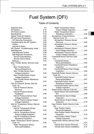
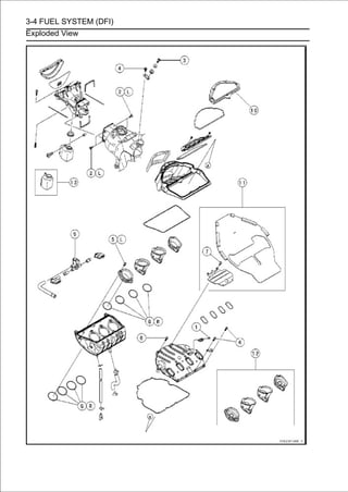
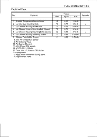
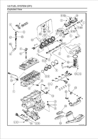
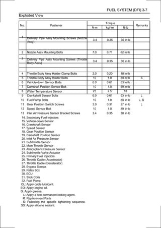
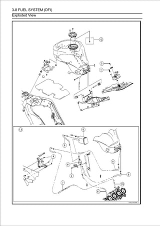
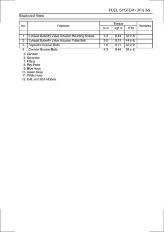
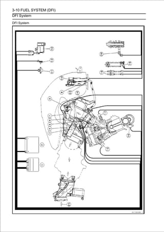
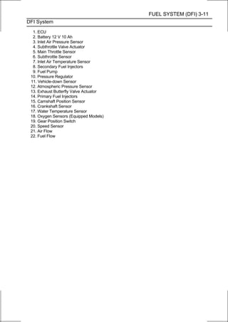
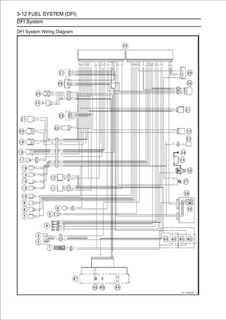
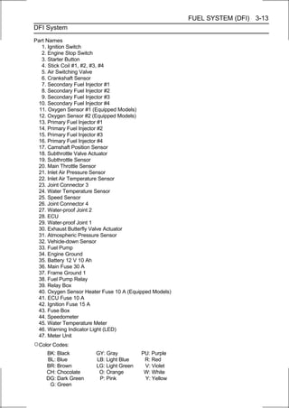
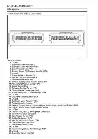
![3-16 FUEL SYSTEM (DFI)
DFI Parts Location
Main Throttle Sensor [A]
Subthrottle Sensor [B]
Subthrottle Valve Actuator [C]
Inlet Air Pressure Sensor [D]
Stick Coils #1, #2, #3, #4 [E]
Air Switching Valve [F]
Water Temperature Sensor [A]
Primary Fuel Injectors #1, #2, #3, #4 [B]
Battery 12 V 10 Ah [A]
Exhaust Butterfly Valve Actuator [B]
Fuse Box [C] (Ignition Fuse 15 A, ECU Fuse 10 A, Oxygen
Sensor Heater Fuse 10 A (Equipped Models))
ECU [A]
Relay Box [B] (Fuel Pump Relay, Radiator Fan Relay)
Immobilizer (Equipped Models)/Kawasaki Diagnostic
System Connector [C]
Vehicle-down Sensor [D]
Atmospheric Pressure Sensor [E]
Fuel Pump [A]
Secondary Fuel Injectors #1, #2, #3, #4 [B]
Inlet Air Temperature Sensor [C]](https://image.slidesharecdn.com/2008-100321201635-phpapp01/85/2008-107-320.jpg)
![FUEL SYSTEM (DFI) 3-17
DFI Parts Location
Camshaft Position Sensor [A]
Crankshaft Sensor [B]
Speed Sensor [A]
Gear Position Switch [B]
Ignition Key [A] (Transponder, Immobilizer System
Equipped Models)
Immobilizer Antenna [B] (Equipped Models)
Ignition Switch [C]
Warning Indicator Light (LED) [D]
Immobilizer Amplifier [A] (Equipped Models)
Oxygen Sensor #1 [A] (Equipped Models)
Oxygen Sensor #2 [B] (Equipped Models)](https://image.slidesharecdn.com/2008-100321201635-phpapp01/85/2008-108-320.jpg)
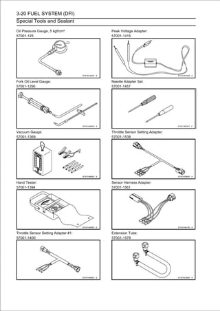
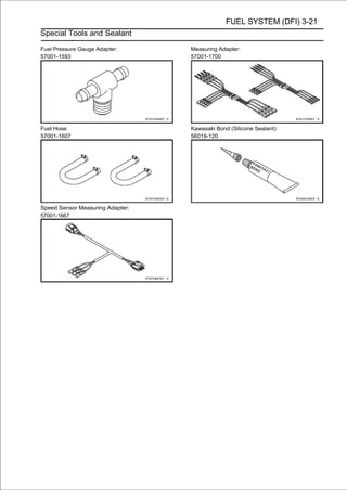
![3-22 FUEL SYSTEM (DFI)
DFI Servicing Precautions
DFI Servicing Precautions
There are a number of important precautions that should be
followed servicing the DFI system.
○This DFI system is designed to be used with a 12 V sealed
battery as its power source. Do not use any other battery
except for a 12 V sealed battery as a power source.
○Do not reverse the battery cable connections. This will
damage the ECU.
○To prevent damage to the DFI parts, do not disconnect the
battery cables or any other electrical connections when
the ignition switch is on or while the engine is running.
○Take care not to short the leads that are directly con-
nected to the battery positive (+) terminal to the chassis
ground.
○When charging, remove the battery from the motorcycle.
This is to prevent ECU damage by excessive voltage.
○Whenever the DFI electrical connections are to be dis-
connected, first turn off the ignition switch, and disconnect
the battery (-) terminal. Do not pull the lead, only the con-
nector. Conversely, make sure that all the DFI electrical
connections are firmly reconnected before starting the en-
gine.
○Connect these connectors until they click [A].
○Do not turn the ignition switch ON while any of the DFI
electrical connectors are disconnected. The ECU memorizes
service codes.
○Do not spray water on the electrical parts, DFI parts,
connectors, leads and wiring.
○If a transceiver is installed on the motorcycle, make sure
that the operation of the DFI system is not influenced by
electric wave radiated from the antenna. Check operation
of the system with the engine at idle. Locate the antenna as
far as possible away from the ECU.
○When any fuel hose is disconnected, do not turn on the
ignition switch. Otherwise, the fuel pump will operate and fuel
will spout from the fuel hose.
○Do not operate the fuel pump if the pump is completely
dry. This is to prevent pump seizure.
○Before removing the fuel system parts, blow the outer sur-
faces of these parts clean with compressed air.
○When any fuel hose is disconnected, fuel may spout out
by residual pressure in the fuel line. Cover the hose joint
with a piece of clean cloth to prevent fuel spillage.
○When installing the fuel hoses, avoid sharp bending, kink-
ing, flattening or twisting, and route the fuel hoses with a
minimum of bending so that the fuel flow will not be ob-
structed.
○Run the hoses according to Cable, Wire, and Hose Routing
section in the Appendix chapter.
○To prevent corrosion and deposits in the fuel system, do
not add to fuel any fuel antifreeze chemicals.](https://image.slidesharecdn.com/2008-100321201635-phpapp01/85/2008-113-320.jpg)
![FUEL SYSTEM (DFI) 3-23
DFI Servicing Precautions
○If the motorcycle is not properly handled, the high pres-
sure inside the fuel line can cause fuel to leak or the hose
to burst. Remove the fuel tank (see Fuel Tank Removal)
and check the fuel hose.
Primary Fuel Hose [A]
Secondary Fuel Hose [B]
Replace the fuel hose if any fraying, cracks or bulges are
noticed.
○To maintain the correct fuel/air mixture (F/A), there must be
no inlet air leaks in the DFI system. Be sure to install the oil
filler plug [A] after filling the engine oil.
Torque - Oil Filler Plug: Hand-tighten](https://image.slidesharecdn.com/2008-100321201635-phpapp01/85/2008-114-320.jpg)
![3-24 FUEL SYSTEM (DFI)
Troubleshooting the DFI System
The warning indicator light (LED) [A] is used for the FI
indicator, immobilizer indicator (equipped models) and oil
pressure warning indicator.
Outline
When a problem occurs with DFI system, the warning in-
dicator light (LED) [A] and FI warning symbol [B] blinks to
alert the rider. In addition, the condition of the problem is
stored in the memory of the ECU. For models equipped with
an immobilizer system, the warning indicator light (LED)
and immobilizer warning symbol [C] blinks, when a prob-
lem occurs in the system.
With the engine stopped and turned in the self-diagnosis
mode, the service code [A] is displayed on the LCD (Liquid
Crystal Display) by the number of two digits.
If the problem is with the following parts, the ECU can not
recognize these problem. Therefore, the warning indicator
light (LED), FI and/or immobilizer warning symbols do not
blinks, and service code is not displayed.
LCD for Meter Unit
Fuel Pump
Primary and Secondary Fuel Injectors
Stick Coil Secondary Wiring and Ground Wiring
ECU Power Source Wiring and Ground Wiring](https://image.slidesharecdn.com/2008-100321201635-phpapp01/85/2008-115-320.jpg)
![FUEL SYSTEM (DFI) 3-25
Troubleshooting the DFI System
When the service code [A] is displayed, for first ask the
rider about the conditions [B] of trouble, and then start to
determine the cause [C] of problem.
As a pre-diagnosis inspection, check the ECU for ground
and power supply, the fuel line for no fuel leaks, and for
correct pressure. The pre-diagnosis items are not indicated
by the warning indicator light (LED) and FI warning symbol.
Don’t rely solely on the DFI self-diagnosis function, use
common sense.
Even when the DFI system is operating normally, the
warning indicator light (LED) and FI warning symbol may
blink under strong electrical interference. Additional
measures are not required. Turn the ignition switch OFF to
stop the indicator light and symbol.
If the warning indicator light (LED) and FI warning symbol of
the motorcycle brought in for repair still blinks, check the
service code.
When the repair has been done, the FI warning symbol
goes off. But the service codes stored in memory of the
ECU are not erased to preserve the problem history. The
problem history can be referred using the KDS (Kawasaki
Diagnostic System) when solving unstable problems.
When the motorcycle is down, the vehicle-down sensor
operates and the ECU shuts off the fuel pump relay, fuel
injectors (primary and secondary) and ignition system. The
ignition switch is left ON. If the starter button is pushed, the
electric starter turns but the engine does not start. When the
starter button is pushed, the warning indicator light (LED)
and FI warning symbol blink but the service code is not
displayed. To start the engine again, raise the motorcycle,
turn the ignition switch OFF, and then ON.
Much of the DFI system troubleshooting work consists of
confirming continuity of the wiring. The DFI parts are
assembled and adjusted with precision, and it is impossible to
disassemble or repair them.](https://image.slidesharecdn.com/2008-100321201635-phpapp01/85/2008-116-320.jpg)
![3-26 FUEL SYSTEM (DFI)
Troubleshooting the DFI System
• When checking the DFI parts, use or resistance. which
can be read two decimal place voltage
a digital meter
○The DFI part connectors [A] have seals [B], including the
ECU. When measuring the input or output voltage with the
connector joined, use the needle adapter set [C]. Insert
the needle adapter inside the seal until the needle adapter
reaches the terminal.
Special Tool - Needle Adapter Set: 57001-1457
CAUTION
Insert the needle adapter straight along the terminal
in the connector to prevent short-circuit between
terminals.
• Makenoting thatposition of the lock [D] and the lead con-
nector,
sure
the
measuring points are correct in the
color before measurement. Do not reverse connections of
a digital meter.
• Be careful not to short-circuit the leads of the DFI or electrical
system parts by contact between adapters.
• Turn the ignition switch ON and measure the voltage with the
connector joined.
CAUTION
Incorrect, reverse connection or short circuit by
needle adapters could damage the DFI or electrical
system parts.
○After measurement, remove the needle adapters and apply
silicone sealant to the seals [A] of the connector [B] for
waterproofing.
Sealant - Kawasaki Bond (Silicone Sealant): 56019-120
• Alwaysfully charged battery is a must for replacing the DFI
parts. A
check battery condition before
conducting
accurate tests of the DFI system.
• Trouble may defectiveone or in some cases all items.
Never replace a
involve
part without determining what
CAUSED the problem. If the problem was caused by
some other item or items, they too must be repaired or
replaced, or the new replacement part will soon fail again.
• Measure coil winding resistance when the DFI part is cold (at
room temperature).
• Make sure all connectors in the circuit are clean and tight,
and examine wires for signs of burning, fraying, short,
etc. Deteriorated wires and bad connections can cause
reappearance of problems and unstable operation of the
DFI system.
If any wiring is deteriorated, replace the wiring.](https://image.slidesharecdn.com/2008-100321201635-phpapp01/85/2008-117-320.jpg)
![FUEL SYSTEM (DFI) 3-27
Troubleshooting the DFI System
• Pull each connector [A] apart and inspect it for corrosion,
dirt, and damage.
If the connector is corroded or dirty, clean it carefully. If it
is damaged, replace it. Connect the connectors securely.
• Check the wiring for continuity.
○Use the wiring diagram to find the ends of the lead which is
suspected of being a problem.
○Connect the hand tester between the ends of the leads.
Special Tool - Hand Tester: 57001-1394
○Set the tester to the × 1 Ω range, and read the tester.
If the tester does not read 0 Ω, the lead is defective. Re-
place the lead or the main harness or the subharness.
○If both ends of a harness [A] are far apart, ground [B] the
one end [C], using a jumper lead [D] and check the con-
tinuity between the end [E] and the ground [F]. This en-
ables to check a long harness for continuity. If the harness is
open, repair or replace the harness.
○When checking a harness [A] for short circuit, open one
end [B] and check the continuity between the other end
[C] and ground [D]. If there is continuity, the harness has
a short circuit to ground, and it must be repaired or re-
placed.
• Narrowtests fromsuspiciousconnectors. by
continuity
down
the ECU
locations repeating the
If no abnormality is found in the wiring or connectors, the
DFI parts are the next likely suspects. Check the part,
starting with input and output voltages. However, there is no
way to check the ECU itself.
If an abnormality is found, replace the affected DFI part. If
no abnormality is found in the wiring, connectors, and DFI
parts, replace the ECU.](https://image.slidesharecdn.com/2008-100321201635-phpapp01/85/2008-118-320.jpg)
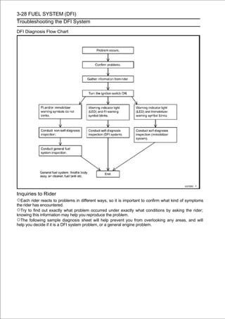
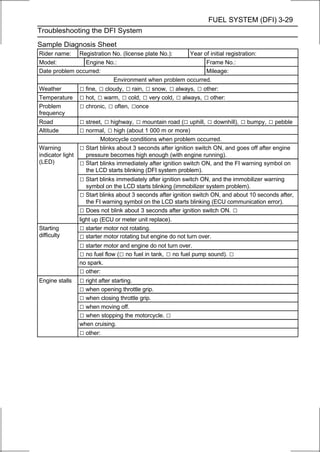
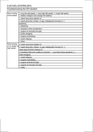
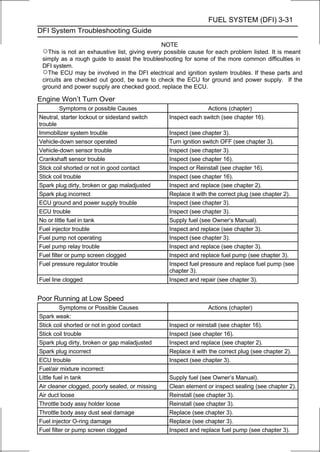
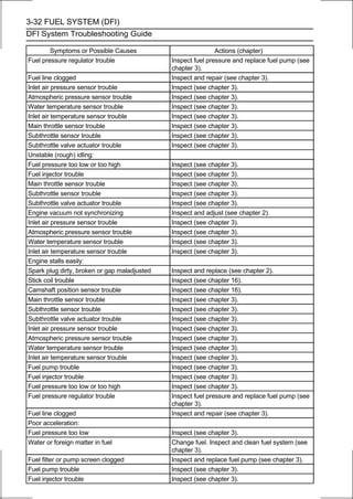
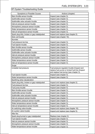
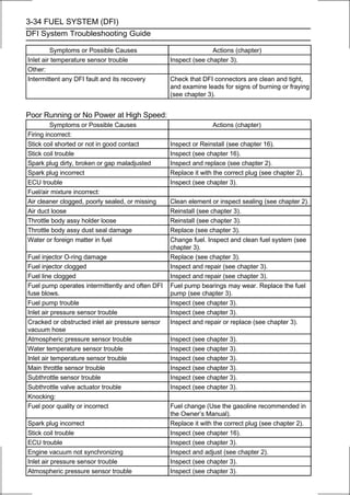
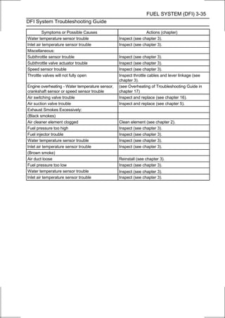
![3-36 FUEL SYSTEM (DFI)
Self-Diagnosis
The warning indicator light (LED) [A] is used for the FI
indicator, immobilizer indicator (equipped models) and oil
pressure warning indicator.
Self-diagnosis Outline
The self-diagnosis system has two modes and can be
switched to another mode by operating the meter unit.
User Mode
The ECU notifies the rider of troubles in DFI system,
ignition system and immobilizer system by blinking the
warning indicator light (LED) [A], FI warning symbol [B] and
immobilizer warning symbol [C] when DFI, ignition and
immobilizer system parts are faulty, and initiates fail-safe
function. In case of serious troubles ECU stops the
injection/ig-
nition/starter motor operation.](https://image.slidesharecdn.com/2008-100321201635-phpapp01/85/2008-127-320.jpg)
![FUEL SYSTEM (DFI) 3-37
Self-Diagnosis
Dealer Mode
The LCD (Liquid Crystal Display) display the service
code(s) [A] to show the problem(s) which the DFI system,
ignition system and immobilizer system has at the moment
of diagnosis.
Self-diagnosis Procedures
○When a problem occurs with the DFI system and ignition
system, the warning indicator light (LED) [A] and FI warning
symbol [B] blinks.
○For models equipped with an immobilizer system, when
a problem occurs with the system, the warning indicator
light (LED) and immobilizer warning symbol [C] blinks.
NOTE
○Use a fully charged battery when conducting
self-diagnosis. Otherwise, the light (LED) and symbol
blinks very slowly or do not blink.](https://image.slidesharecdn.com/2008-100321201635-phpapp01/85/2008-128-320.jpg)
![3-38 FUEL SYSTEM (DFI)
Self-Diagnosis
• Turn the ignition switch ON.
• Push the MODE button [A] to display the odometer.
• Push the RESET button [A] for more than two seconds.
• The digits. code [B] is displayed on the LCD by the number
of two
service
○After switching to the engine speed setting mode of the
shift up indicator light (LED) from odometer display, the
service code can not be displayed even if pushing the
RESET button for more than two seconds.
• Any of the following procedures ends self-diagnosis.
○When the service code is displayed on the LCD, push the
RESET button for more than two seconds.
○When the ignition switch is turned OFF.](https://image.slidesharecdn.com/2008-100321201635-phpapp01/85/2008-129-320.jpg)
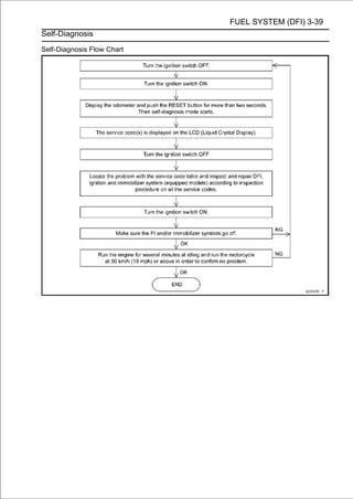
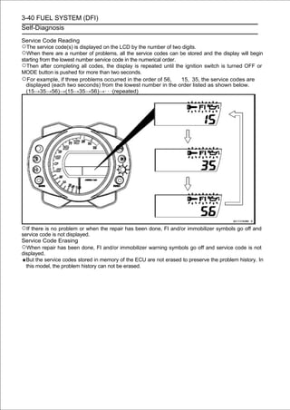

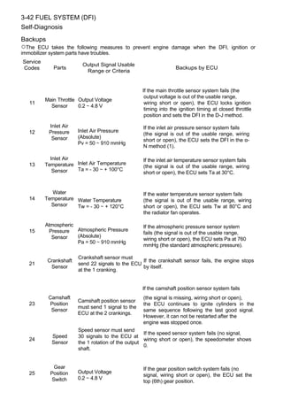
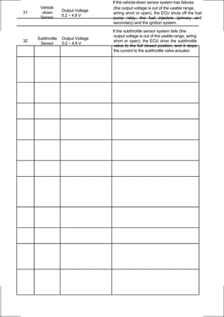
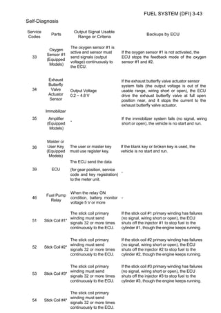
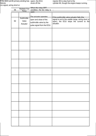
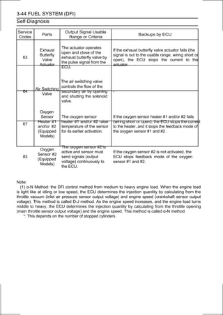
![FUEL SYSTEM (DFI) 3-45
Main Throttle Sensor (Service Code 11)
The main throttle sensor is a rotating variable resistor that
change output voltage according to throttle operating. The
ECU senses this voltage change and determines fuel injection
quantity, and ignition timing according to engine rpm, and
throttle opening.
Input Terminal [A]: BL
Output Terminal [B]: Y/W
Ground Terminal [C]: BR/BK
Main Throttle Sensor Removal/Adjustment
CAUTION
Do not remove or adjust the main throttle sensor
since it has been adjusted and set with precision at
the factory.
Never drop the throttle body assy, especially on a
hard surface. Such a shock to the main throttle sensor
can damage it.
Main Throttle Sensor Connector [A]
Main Throttle Sensor Input Voltage Inspection
NOTE
○Be sure the battery is fully charged.
• Turn the ignition switch OFF.
• Remove Removal). body assy temporarily (see Throttle
Body Assy
the throttle
• Disconnect the main throttle sensor connector [A].
• Connect the harness adapter sensor connector.
harness connector and main throttle
[A] between the main
Special Tool - Throttle Sensor Setting Adapter: 57001
-1538
• Reinstall the throttle body assy (See Throttle Body Assy
Installation).
• Connect a digital meter to the harness adapter leads.
Main Throttle Sensor Input Voltage
Connections to Adapter:
Digital Meter (+) → W (sensor BL) lead
Digital Meter (-) → BK (sensor BR/BK) lead
• Measure the input voltage with the engine stopped and
with the connector joined.
• Turn the ignition switch ON.
Input Voltage
Standard: DC 4.75 ∼ 5.25 V
• Turn the ignition switch OFF.
If the reading is within the standard, check the output volt-
age (see Main Throttle Sensor Output Voltage Inspec-
tion).](https://image.slidesharecdn.com/2008-100321201635-phpapp01/85/2008-138-320.jpg)
![3-46 FUEL SYSTEM (DFI)
Main Throttle Sensor (Service Code 11)
If the reading is out of the standard, remove the ECU
and check the wiring for continuity between main harness
connectors.
Special Tool - Hand Tester: 57001-1394
○Disconnect the ECU and sensor connectors.
Wiring Continuity Inspection
ECU Connector (Black) [A] ←→
Main Throttle Sensor Connector [B]
BL lead (ECU terminal 7) [C]
BR/BK lead (ECU terminal 34) [D]
If the wiring is good, check the ECU for its ground and
power supply (see ECU Power Supply Inspection).
If the ground and power supply are good, replace the ECU
(see ECU Removal/Installation).
Main Throttle Sensor Output Voltage Inspection
• Measure the output voltage at the main throttle sensor in
the same way as input voltage inspection, note the follow-
ing.
○Disconnect the main throttle sensor connector and con-
nect the harness adapter [A] between these connectors.
Special Tool - Throttle Sensor Setting Adapter: 57001
-1538
Main Throttle Sensor Output Voltage
Connections to Adapter:
Digital Meter (+) → R (sensor Y/W) lead
Digital Meter (-) → BK (sensor BR/BK) lead
• Start the engine and warm it up thoroughly.
• Check idle speed to ensure the throttle opening is correct. Idle
Speed
Standard: 1 100 ±50 r/min (rpm)
If the idle speed is out of the specified range, adjust it
(see Idle Speed Inspection in the Periodic Maintenance
chapter).](https://image.slidesharecdn.com/2008-100321201635-phpapp01/85/2008-139-320.jpg)
![FUEL SYSTEM (DFI) 3-47
Main Throttle Sensor (Service Code 11)
• Turn the ignition switch OFF.
• with the connector joined. with the engine stopped, and
Measure the output voltage
• Turn the ignition switch ON.
Output Voltage
Standard: DC 0.645 ∼ 0.675 V at idle throttle opening
DC 3.93 ∼ 3.95 V at full throttle opening (for
reference)
NOTE
○Open the throttle, confirm the output voltage will be
raise.
○The standard voltage refers to the value when the volt-
age reading at the Input Voltage Inspection shows 5 V
exactly.
○When the input voltage reading shows other than 5 V,
derive a voltage range as follows.
Example:
In the case of a input voltage of 4.75 V.
0.645 × 4.75 ÷ 5.00 = 0.613 V
0.675 × 4.75 ÷ 5.00 = 0.641 V
Thus, the valid range is 0.613 ∼ 0.641 V
• Turn the ignition switch OFF.
If the reading is out of the standard, check the main throttle
sensor resistance (see Main Throttle Sensor Resistance
Inspection).
If the reading is within the standard, remove the ECU and
check the wiring for continuity between main harness con-
nectors.
Special Tool - Hand Tester: 57001-1394
○Disconnect the ECU and sensor connectors.
Wiring Continuity Inspection
ECU Connector (Black) [A] ←→
Main Throttle Sensor Connector [B]
Y/W lead (ECU terminal 26) [C]
BR/BK lead (ECU terminal 34) [D]
If the wiring is good, check the ECU for its ground and
power supply (see ECU Power Supply Inspection).
If the ground and power supply are good, replace the ECU
(see ECU Removal/Installation).
Main Throttle Sensor Resistance Inspection
• Turn the ignition switch OFF.
• Disconnect the main throttle sensor connector.
• Connect a digital meter [A] to the main throttle sensor
connector [B].
• Measure the main throttle sensor resistance.
Main Throttle Sensor Resistance
Connections: BL lead [C] ←→ BR/BK lead [D]
Standard: 4 ∼ 6 kΩ
If the reading is out of the standard, replace the throttle
body assy.
If the reading is within the standard, but the problem still
exists, replace the ECU (see ECU Removal/Installation).](https://image.slidesharecdn.com/2008-100321201635-phpapp01/85/2008-140-320.jpg)
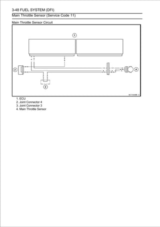
![FUEL SYSTEM (DFI) 3-49
Inlet Air Pressure Sensor (Service Code 12)
Inlet Air Pressure Sensor Removal
CAUTION
Never drop the inlet air pressure sensor, especially
on a hard surface. Such a shock to the sensor can
damage it.
• Remove:
Air Cleaner Housing (see Air Cleaner Housing Removal)
Inlet Air Pressure Sensor Connector [A]
• Remove the inlet air pressure sensor [B] from the rubber
damper in the bracket [C] and separate the vacuum hose
[D].
Inlet Air Pressure Sensor Installation
NOTE
○The inlet air pressure sensor is the same part as the
atmospheric pressure sensor except that the sensor has a
vacuum hose and different wiring.
• Installation is the reverse of removal.
Inlet Air Pressure Sensor Input Voltage Inspection
NOTE
○Be sure the battery is fully charged.
• Turn the ignition switch OFF.
• Remove the fuel tank (see Fuel Tank Removal).
• Disconnect the inlet air pressure sensor connector and
connect the harness adapter [A] between these connec-
tors.
Special Tool - Sensor Harness Adapter: 57001-1561
• Connect a digital meter to the harness adapter leads.
Inlet Air Pressure Sensor Input Voltage
Connections to Adapter:
Digital Meter (+) → G (sensor BL) lead
Digital Meter (-) → BK (sensor BR/BK) lead
• Measure the input voltage with the engine stopped and
with the connector joined.
• Turn the ignition switch ON.
Input Voltage
Standard: DC 4.75 ∼ 5.25 V
• Turn the ignition switch OFF.
If the reading is within the standard, check the output volt-
age (see Inlet Air Pressure Sensor Output Voltage Inspec-
tion).](https://image.slidesharecdn.com/2008-100321201635-phpapp01/85/2008-142-320.jpg)
![3-50 FUEL SYSTEM (DFI)
Inlet Air Pressure Sensor (Service Code 12)
If the reading is out of the standard, remove the ECU
and check the wiring for continuity between main harness
connectors.
Special Tool - Hand Tester: 57001-1394
○Disconnect the ECU and sensor connectors.
Wiring Continuity Inspection
ECU Connector (Black) A] ←→
Inlet Air Pressure Sensor Connector [B]
BL lead (ECU terminal 7) [C]
BR/BK lead (ECU terminal 34) [D]
If the wiring is good, check the ECU for its ground and
power supply (see ECU Power Supply Inspection).
If the ground and power supply are good, replace the ECU
(see ECU Removal/Installation).
Inlet Air Pressure Sensor Output Voltage
Inspection
• Measure the output voltage at the inlet air pressure sen-
sor in the same way as input voltage inspection, note the
following.
○Disconnect the inlet air pressure sensor connector and
connect the harness adapter [A] between these connec-
tors.
Special Tool - Sensor Harness Adapter: 57001-1561
Inlet Air Pressure Sensor Output Voltage
Connections to Adapter:
Digital Meter (+) → G/W (sensor Y/BL) lead
Digital Meter (-) → BK (sensor BR/BK) lead
• Measure the output voltage with the engine stopped, and
with the connector joined.
• Turn the ignition switch ON.
Output Voltage
Usable Range: DC 3.80 ∼ 4.20 V at standard
atmospheric pressure (101.32 kPa, 76
cmHg)
NOTE
○The output voltage changes according to local
atmospheric pressure.
• Turn the ignition switch OFF.
If the reading is out of the usable range, replace the sen-
sor.](https://image.slidesharecdn.com/2008-100321201635-phpapp01/85/2008-143-320.jpg)
![FUEL SYSTEM (DFI) 3-51
Inlet Air Pressure Sensor (Service Code 12)
If the reading is within the usable range, remove the ECU
and check the wiring for continuity between main harness
connector.
Special Tool - Hand Tester: 57001-1394
○Disconnect the ECU and sensor connectors.
Wiring Continuity Inspection
ECU Connector (Black) [A] ←→
Inlet Air Pressure Sensor Connector [B]
Y/BL lead (ECU terminal 28) [C]
BR/BK lead (ECU terminal 34) [D]
If the wiring is good, check the sensor for various vacuum.
• Remove the inlet air pressure sensor [A] and disconnect
the vacuum hose from the sensor.
• Connect an auxiliary hose [B] to the inlet air pressure sen-
sor.
• Temporarily install the inlet air pressure sensor.
○Connect a digital meter [C], vacuum gauge [D], the fork oil
level gauge [E] and the harness adapter to the inlet air
pressure sensor.
Special Tools - Fork Oil Level Gauge: 57001-1290
Vacuum Gauge: 57001-1369
Sensor Harness Adapter: 57001-1561
Inlet Air Pressure Sensor Output Voltage
Connections to Adapter:
Digital Meter (+) → G/W (sensor Y/BL) lead
Digital Meter (-) → BK (sensor BR/BK) lead
○Turn the ignition switch ON.
○Measure the inlet air pressure sensor output voltage from
various vacuum readings, while pulling the handle of the fork
oil level gauge.
○Check the inlet air pressure sensor output voltage, using
the following formula and chart.
Suppose:
Pg: Vacuum Pressure (Gauge) of Throttle Body
Pl: Local Atmospheric Pressure (Absolute) measured by
a barometer
Pv: Vacuum Pressure (Absolute) of Throttle Body
Vv: Sensor Output Voltage (V)](https://image.slidesharecdn.com/2008-100321201635-phpapp01/85/2008-144-320.jpg)
![3-52 FUEL SYSTEM (DFI)
Inlet Air Pressure Sensor (Service Code 12)
then
Pv = Pl - Pg
For example, suppose the following data is obtained:
Pg = 8 cmHg (Vacuum Gauge Reading)
Pl = 70 cmHg (Barometer Reading)
Vv = 3.2 V (Digital Meter Reading)
then
Pv = 70 - 8 = 62 cmHg (Absolute)
Plot this Pv (62 cmHg) at a point [1] on the chart and draw a
vertical line through the point. Then, you can get the usable
range [2] of the sensor output voltage.
Usable range = 3.08 ∼ 3.48 V
Plot Vv (3.2 V) on the vertical line. → Point [3].
Results: In the chart, Vv is within the usable range and
the sensor is normal.
If the reading is out of the usable range, replace the sen-
sor.
If the reading is within the usable range, check the ECU
for its ground and power supply (see ECU Power Supply
Inspection).
If the ground and power supply are good, replace the ECU
(see ECU Removal/Installation).](https://image.slidesharecdn.com/2008-100321201635-phpapp01/85/2008-145-320.jpg)
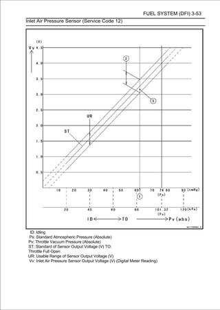
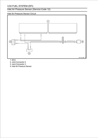
![FUEL SYSTEM (DFI) 3-55
Inlet Air Temperature Sensor (Service Code 13)
Inlet Air Temperature Sensor Removal/Installation
CAUTION
Never drop the inlet air temperature sensor,
especially on a hard surface. Such a shock to the
sensor can damage it.
• Remove the fuel tank (see Fuel Tank Removal).
• Disconnect the connector [A].
• Remove the screw [B].
• Pull out the inlet air temperature sensor [C].
• Put the inlet air temperature sensor into the air cleaner
housing.
• Tighten:
Torque - Inlet Air Temperature Sensor Screw: 1.2 N·m (0.12
kgf·m, 11 in·lb)
Inlet Air Temperature Sensor Output Voltage
Inspection
NOTE
○Be sure the battery is fully charged.
• Turn the ignition switch OFF.
• Remove the fuel tank (see Fuel Tank Removal).
• Disconnect the inlet air temperature[A] between these
and connect the harness adapter
sensor connector
connectors as shown in the figure.
Main Harness [B]
Inlet Air Temperature Sensor [C]
Special Tool - Measuring Adapter: 57001-1700
• Connect a digital meter [D] to the harness adapter leads.
Inlet Air Temperature Sensor Output Voltage
Connections to Adapter:
Digital Meter (+) → R (sensor Y) lead
Digital Meter (-) → BK (sensor BR/BK) lead
• the connectoroutput voltage with the engine stopped and
Measure the
joined.
• Turn the ignition switch ON.
Output Voltage
Standard: About DC 2.25 ∼ 2.50 V at inlet air
temperature 20°C (68°F)
NOTE
○The output voltage changes according to the inlet air
temperature.
• Turn the ignition switch OFF.
If the reading is within the standard, check the ECU for
its ground and power supply (see ECU Power Supply In-
spection).
If the ground and power supply are good, replace the ECU
(see ECU Removal/Installation).](https://image.slidesharecdn.com/2008-100321201635-phpapp01/85/2008-148-320.jpg)
![3-56 FUEL SYSTEM (DFI)
Inlet Air Temperature Sensor (Service Code 13)
If the reading is out of the standard, remove the ECU
and check the wiring for continuity between main harness
connectors.
Special Tool - Hand Tester: 57001-1394
○Disconnect the ECU and sensor connectors.
Wiring Continuity Inspection
ECU Connector (Black) [A] ←→
Inlet Air Temperature Sensor Connector [B]
Y lead (ECU terminal 8) [C]
BR/BK lead (ECU terminal 34) [D]
If the wiring is good, check the inlet air temperature sensor
resistance (see Inlet Air Temperature Sensor Resistance
Inspection).
Inlet Air Temperature Sensor Resistance
Inspection
• Remove the inlet air temperature sensor (see Inlet Air
Temperature Sensor Removal/Installation).
• Suspend the sensor [A] in a container of machine oil so
that the heat-sensitive portion is submerged.
• Suspend a thermometer [B] with the heat-sensitive por-
tion [C] located in almost the same depth with the sensor.
NOTE
○The sensor and thermometer must not touch the
container side or bottom.
• Place temperature ofoveroil while stirring the and gradually
raise the
the container
the
a source of heat
oil gently
for even temperature.
• Using a digital meter, measure the internal resistance
of the sensor across the terminals at the temperatures
shown in the following.
Inlet Air Temperature Sensor Resistance
Standard: 5.4 ∼ 6.6 kΩ at 0°C (32°F)
0.29 ∼ 0.39 kΩ at 80°C (176°F)
If the reading is out of the standard, replace the sensor.
If the reading is within the standard, but the problem still
exists, replace the ECU (see ECU Removal/Installation).](https://image.slidesharecdn.com/2008-100321201635-phpapp01/85/2008-149-320.jpg)
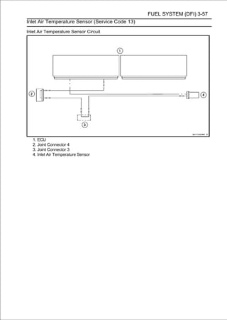
![3-58 FUEL SYSTEM (DFI)
Water Temperature Sensor (Service Code 14)
Water Temperature Sensor Removal/Installation
CAUTION
Never drop the water temperature sensor,
especially on a hard surface. Such a shock to the
sensor can damage it.
• Remove the throttle body assy (see Throttle Body Assy
Removal).
• Drain the coolant (see Coolant Change in the Periodic
Maintenance chapter).
• Remove:
Connector [A]
Water Temperature Sensor [B] with Gasket [C]
• Replace the gasket with a new one.
• Tighten:
Torque - Water Temperature Sensor: 25 N·m (2.5 kgf·m, 18
ft·lb)
• Fill the engineCoolant Change in the Periodic Mainte-the cool-
ing system (see
with coolant and bleed the air from
nance chapter).
Water Temperature Sensor Output Voltage
Inspection
NOTE
○Be sure the battery is fully charged.
• Turn the ignition switch OFF.
• Remove the fuel tank (see Fuel Tank Removal).
• Disconnect the water temperature sensor connector and
connect the harness adapter [A] between these connec-
tors as shown in the figure.
Main Harness [B]
Water Temperature Sensor [C]
Special Tool - Measuring Adapter: 57001-1700
• Connect a digital meter [D] to the harness adapter leads.
Water Temperature Sensor Output Voltage
Connections to Adapter:
Digital Meter (+) → R (sensor O) lead
Digital Meter (-) → BK (sensor BR) lead
• Measure the output voltage with the engine stopped and
the connector joined.
• Turn the ignition switch ON.
Output Voltage
Standard: About DC 2.80 ∼ 2.97 V at 20°C (68°F)
NOTE
○The output voltage changes according to the coolant
temperature in the engine.
• Turn the ignition switch OFF.
If the reading is within the standard, check the ECU for
its ground, and power supply (see ECU Power Supply
Inspection).
If the ground and power supply are good, replace the ECU
(see ECU Removal/Installation).](https://image.slidesharecdn.com/2008-100321201635-phpapp01/85/2008-151-320.jpg)
![FUEL SYSTEM (DFI) 3-59
Water Temperature Sensor (Service Code 14)
If the reading is out of the standard, remove the ECU
and check the wiring for continuity between main harness
connectors.
Special Tool - Hand Tester: 57001-1394
○Disconnect the ECU and sensor connectors.
Wiring Continuity Inspection
ECU Connector (Black) [A] ←→
Water Temperature Sensor Connector [B]
O lead (ECU terminal 25) [C]
BR/BK lead (ECU terminal 34) [D]
If the wiring is good, check the water temperature sensor
resistance (see Water Temperature Sensor Resistance
Inspection).
Water Temperature Sensor Resistance Inspection
• Refer to the Water Temperature Sensor Inspection in the
Electrical System chapter.
If the reading is within the standard, but the problem still
exists, replace the ECU (see ECU Removal/Installation).
Water Temperature Sensor Circuit
1. ECU
2. Joint Connector 4
3. Joint Connector 3
4. Water Temperature Sensor
5. Meter Unit](https://image.slidesharecdn.com/2008-100321201635-phpapp01/85/2008-152-320.jpg)
![3-60 FUEL SYSTEM (DFI)
Atmospheric Pressure Sensor (Service Code 15)
Atmospheric Pressure Sensor Removal
CAUTION
Never drop the atmospheric pressure sensor,
especially on a hard surface. Such a shock to the
sensor can damage it.
• Removechapter).seat cover (see Seat Cover Removal in
the Frame
the left
• Disconnect the sensor connector [A].
• Remove theinatmospheric pressure sensor [B] from the
rubber damper the rear fender rear bracket.
Atmospheric Pressure Sensor Installation
NOTE
○The atmospheric pressure sensor is the same part as
the inlet air pressure sensor except that the inlet air
pressure sensor has the vacuum hose and different
wiring.
• Installation is the reverse of removal.
Atmospheric Pressure Sensor Input Voltage
Inspection
NOTE
○Be sure the battery is fully charged.
• Turn the ignition switch OFF.
• Removechapter).seat cover (see Seat Cover Removal in
the Frame
the left
• Disconnect the atmospheric pressure sensor connector
and connect the harness adapter [A] between these con-
nectors.
Special Tool - Sensor Harness Adapter: 57001-1561
• Connect a digital meter to the harness adapter leads.
Atmospheric Pressure Sensor Input Voltage
Connections to Adapter:
Digital Meter (+) → G (sensor BL) lead
Digital Meter (-) → BK (sensor BR/BK) lead
• Measure the input voltage with the engine stopped and
with the connector joined.
• Turn the ignition switch ON.
Input Voltage
Standard: DC 4.75 ∼ 5.25 V
• Turn the ignition switch OFF.
If the reading is within the standard, check the output
voltage (Atmospheric Pressure Sensor Output Voltage
Inspection).](https://image.slidesharecdn.com/2008-100321201635-phpapp01/85/2008-153-320.jpg)
![FUEL SYSTEM (DFI) 3-61
Atmospheric Pressure Sensor (Service Code 15)
If the input voltage is out of the standard, remove the ECU
and check the wiring for continuity between main harness
connectors.
Special Tool - Hand Tester: 57001-1394
○Disconnect the ECU and sensor connectors.
Wiring Continuity Inspection
ECU Connector (Black) [A] ←→
Atmospheric Pressure Sensor Connector [B]
BL lead (ECU terminal 7) [C]
BR/BK lead (ECU terminal 34) [D]
If the wiring is good, check the ECU for its ground and
power supply (see ECU Power Supply Inspection).
If the ground and power supply are good, replace the ECU
(see ECU Removal/Installation).
Atmospheric Pressure Sensor Output Voltage
Inspection
• Measure the output voltage at the atmospheric pressure
sensor in the same way as input voltage inspection, note
the following.
○Disconnect the atmospheric pressure sensor connector
and connect the harness adapter [A] between these con-
nectors.
Special Tool - Sensor Harness Adapter: 57001-1561
Atmospheric Pressure Sensor Output Voltage
Connections to Adapter:
Digital Meter (+) → G/W (sensor G/W) lead
Digital Meter (-) → BK (sensor BR/BK) lead
• Measure the output voltage with the engine stopped and
with the connector joined.
• Turn the ignition switch ON.
Output Voltage
Usable Range: DC 3.80 ∼ 4.20 V at the standard
atmospheric pressure (101.32 kPa, 76
cmHg abs.)
NOTE
○The output voltage changes according to the local
atmospheric pressure.
• Turn the ignition switch OFF.
If the reading is out of the usable range, replace the sen-
sor.](https://image.slidesharecdn.com/2008-100321201635-phpapp01/85/2008-154-320.jpg)
![3-62 FUEL SYSTEM (DFI)
Atmospheric Pressure Sensor (Service Code 15)
If the reading is within the standard, remove the ECU and
check the wiring for continuity between main harness con-
nector.
Special Tool - Hand Tester: 57001-1394
○Disconnect the ECU and sensor connectors.
Wiring Continuity Inspection
ECU Connector (Black) [A] ←→
Atmospheric Pressure Sensor Connector [B]
G/W lead (ECU terminal 11) [C]
BR/BK lead (ECU terminal 34) [D]
If the wiring is good, check the sensor for various vacuum.
○Determine the local altitude (elevation).
If you know the local altitude, use the chart in this section.
If you know the local atmospheric pressure using a
barometer, substitute the atmospheric pressure for Pv
(vacuum pressure) in the inlet air pressure sensor chart
(see Inlet Air Pressure Sensor Output Voltage Inspec-
tion).
○Get the usable range of the atmospheric pressure sensor
output voltage in the same way as Output Voltage Inspec-
tion of the inlet air pressure sensor and check if Va (output
voltage) is within the usable range or not.
If the reading is out of the usable range, replace the sen-
sor.
If the reading is within the usable range, check the ECU
for its ground, and power supply (see ECU Power Supply
Inspection).
If the ground and power supply are good, replace the ECU
(see ECU Removal/Installation).](https://image.slidesharecdn.com/2008-100321201635-phpapp01/85/2008-155-320.jpg)
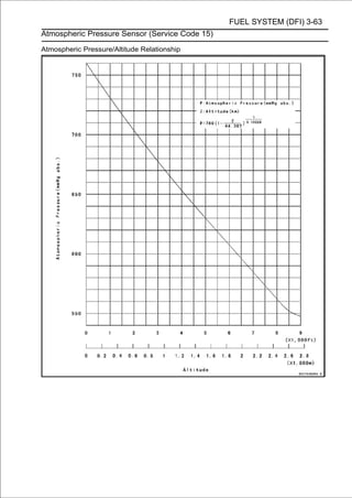
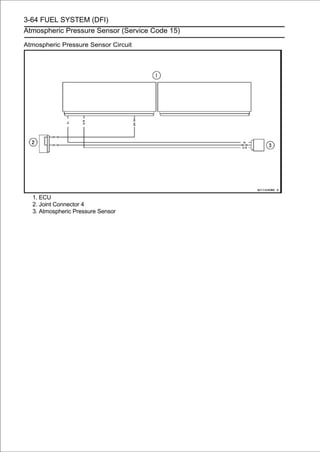
![FUEL SYSTEM (DFI) 3-65
Crankshaft Sensor (Service Code 21)
The crankshaft sensor has no power source, and when
the engine stops, the crankshaft sensor generates no sig-
nals.
Crankshaft Sensor Removal/Installation
• Refer to the Crankshaft Sensor Removal/Installation in
the Electrical System chapter.
Crankshaft Sensor Resistance Inspection
• Refer to the Crankshaft Sensor Inspection in the Electrical
System chapter.
If the reading is within the standard, check the peak volt-
age (see Crankshaft Sensor Peak Voltage Inspection).
Crankshaft Sensor Peak Voltage Inspection
• Refer to the Crankshaft Sensor Peak Voltage Inspection in
the Electrical System chapter.
If the reading is within the standard, remove the ECU and
check the wiring for continuity between main harness con-
nectors.
Special Tool - Hand Tester: 57001-1394
○Disconnect the ECU and sensor connectors.
Wiring Continuity Inspection
ECU Connector (Black) [A] ←→
Crankshaft Sensor Connector [B]
R/BL lead (ECU terminal 29) [C]
BK lead (ECU terminal 30) [D]
If the wiring is good, check the ECU for its ground and
power supply (see ECU Power Supply Inspection).
If the ground and power supply are good, replace the ECU
(see ECU Removal/Installation).](https://image.slidesharecdn.com/2008-100321201635-phpapp01/85/2008-158-320.jpg)
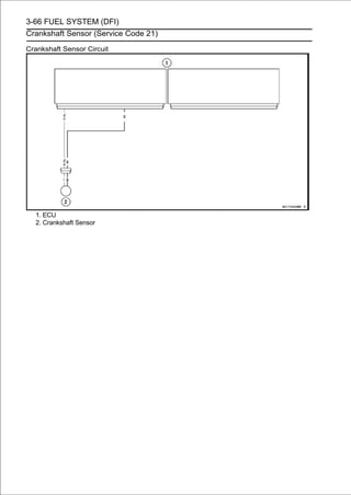
![FUEL SYSTEM (DFI) 3-67
Camshaft Position Sensor (Service Code 23)
The camshaft position sensor detects the position of the
camshaft, and distinguishes the cylinder.
The camshaft position sensor has no power source, and
when the engine stops, the camshaft position sensor
generates no signals.
Camshaft Position Sensor Removal/Installation
• Refer to the Camshaft Position Sensor Removal/Installa-
tion in the Electrical System chapter.
Camshaft Position Sensor Resistance Inspection
• Refer to the Camshaft Position Sensor Inspection in the
Electrical System chapter.
If the reading is within the standard, check the peak volt-
age (see Camshaft Position Sensor Peak Voltage Inspec-
tion).
Camshaft Position Sensor Peak Voltage
Inspection
• Refer to the Camshaft Position Sensor Peak Voltage
Inspection in the Electrical System chapter.
If the reading is within the standard, remove the ECU and
check the wiring for continuity between main harness con-
nectors.
Special Tool - Hand Tester: 57001-1394
○Disconnect the ECU and sensor connectors.
Wiring Continuity Inspection
ECU Connector (Black) [A] ←→
Camshaft Position Sensor Connector [B]
W/Y lead [C]
Y/R lead (ECU terminal 13) [D]
BR/BK lead (ECU terminal 34) [E]
If the wiring is good, check the ECU for its ground and
power supply (see ECU Power Supply Inspection).
If the ground and power supply are good, replace the ECU
(see ECU Removal/Installation).](https://image.slidesharecdn.com/2008-100321201635-phpapp01/85/2008-160-320.jpg)
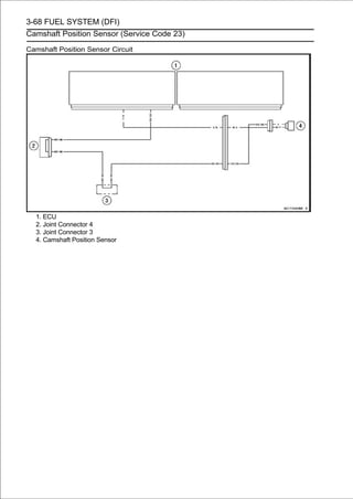
![FUEL SYSTEM (DFI) 3-69
Speed Sensor (Service Code 24)
Speed Sensor Removal/Installation
• Refer to the Speed Sensor Removal/Installation in the
Electrical System chapter.
Speed Sensor Input Voltage Inspection
NOTE
○Be sure the battery is fully charged.
• Turn the ignition switch OFF.
• Remove the Final Drive chapter). (see Engine Sprocket
Removal in
the engine sprocket cover
• Disconnect the speed sensor connector [A].
• Connect the harness adapter [A] between
harness connector and speed sensor connector.
the main
Special Tool - Speed Sensor Measuring Adapter: 57001
-1667
• Connect a digital meter to the harness adapter leads.
Speed Sensor Input Voltage
Connections to Adapter:
Digital Meter (+) → BL (sensor BL) lead
Digital Meter (-) → BK/Y (sensor BK/Y) lead
• Measure the input voltage with the engine stopped and
with the connector joined.
• Turn the ignition switch ON.
Input Voltage
Standard: DC 4.75 ∼ 5.25 V
• Turn the ignition switch OFF.
If the reading is within the standard, check the output volt-
age (see Speed Sensor Output Voltage Inspection).
If the reading is out of the standard, remove the ECU
and check the wiring for continuity between main harness
connectors.
Special Tool - Hand Tester: 57001-1394
○Disconnect the ECU and sensor connectors.
Wiring Continuity Inspection
ECU Connector (Black) [A] ←→
Speed Sensor Connector [B]
BL lead (ECU terminal 7) [C]
BK/Y lead [D]
BR/BK lead (ECU terminal 34) [E]
If the wiring is good, check the ECU for its ground and
power supply (see ECU Power Supply Inspection).
If the ground and power supply are good, replace the ECU
(see ECU Removal/Installation).](https://image.slidesharecdn.com/2008-100321201635-phpapp01/85/2008-162-320.jpg)
![3-70 FUEL SYSTEM (DFI)
Speed Sensor (Service Code 24)
Speed Sensor Output Voltage Inspection
• Using the stand, raise the rear wheel off the ground.
• Measure the output voltage at the speed sensor in the
same way as input voltage inspection, note the following.
○Disconnect the speed sensor connector and connect the
harness adapter [A] between these connectors.
Special Tool - Speed Sensor Measuring Adapter: 57001
-1667
Speed Sensor Output Voltage
Connections to Adapter:
Digital Meter (+) → BL/Y (sensor BL/Y) lead
Digital Meter (-) → BK/Y (sensor BK/Y) lead
• Measure the output voltage with the engine stopped and
with the connector joined.
• Turn the ignition switch ON.
Output Voltage
Standard: About DC 0.05 ∼ 0.09 V or DC 4.5 ∼ 4.9 V at
ignition switch ON and 0 km/h
NOTE
○Rotate the rear wheel by hand, confirm the output voltage
will be raise or lower.
• Turn the ignition switch OFF.
If the reading is out of the standard, replace the sensor.
If the reading is within the standard, remove the ECU and
check the wiring for continuity between main harness con-
nectors.
Special Tool - Hand Tester: 57001-1394
○Disconnect the ECU and sensor connectors.
Wiring Continuity Inspection
ECU Connector (Black) [A] ←→
Speed Sensor Connector [B]
BL/Y lead (ECU terminal 12) [C]
BK/Y lead [D]
BR/BK lead (ECU terminal 34) [E]
If the wiring is good, check the ECU for its ground and
power supply (see ECU Power Supply Inspection).
If the ground and power supply are good, replace the ECU
(see ECU Removal/Installation).](https://image.slidesharecdn.com/2008-100321201635-phpapp01/85/2008-163-320.jpg)
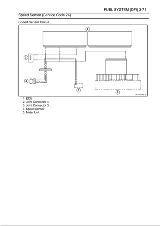
![3-72 FUEL SYSTEM (DFI)
Gear Position Switch (Service Code 25)
Gear Position Switch Removal/Installation
• Refer to the Gear Position Switch Removal/Installation in
the Electrical System chapter.
Gear Position Switch Resistance Inspection
• Refer to the Gear Position Switch Inspection in the
Electrical System chapter.
If the reading is as the specified, check the output voltage
(see Gear Position Switch Output Voltage Inspection).
Gear Position Switch Output Voltage Inspection
NOTE
○Be sure the battery is fully charged.
• Turn the ignition switch OFF.
• Remove the ECU (seeECU connectors.
○Do not disconnect the
ECU Removal).
• Connect a digital meter [A] to the connector [B] with the
needle adapter set.
Special Tool - Needle Adapter Set: 57001-1457
Gear Position Switch Output Voltage
Connections to ECU Connector:
Digital Meter (+) → W/Y lead (terminal 4)
Digital Meter (-) → Battery (-) terminal
• Measure the switch joined.voltage with the engine stopped
and with the connector
input
• Turn the ignition switch ON.
○When changing the gear position from lower gear to
higher gear, raise the rear wheel off the ground with the
stand and rotate the rear wheel by hand.
Output Voltage at 1 ∼ 6 Gear Positions
Standard:
1st About 3.0 V
2nd About 2.5 V
3rd About 2.0 V
4th About 1.5 V
5th About 1.1 V
6th About 0.7 V
• Turn the ignition switch OFF.
If the reading is out of the standard, check the wiring for
continuity, using the wiring diagram in this section.
Special Tool - Hand Tester: 57001-1394
If the wiring is good, check the ECU for its ground and
power supply (see ECU Power Supply Inspection).
If the ground and power supply are good, replace the ECU
(see ECU Removal/Installation).](https://image.slidesharecdn.com/2008-100321201635-phpapp01/85/2008-165-320.jpg)
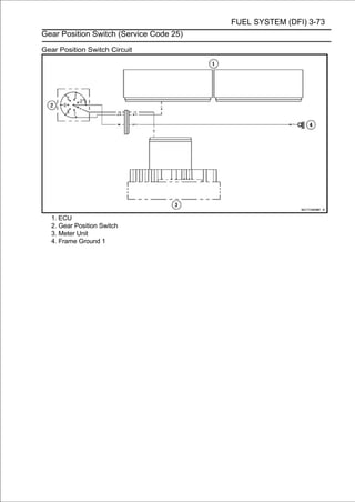
![3-74 FUEL SYSTEM (DFI)
Vehicle-down Sensor (Service Code 31)
This sensor has a weight [A] with two magnets inside,
and sends a signal to the ECU. But when the motorcycle
banks 60 ∼ 70° or more to either side (in fact falls down),
the weight turns and the signal changes. The ECU senses
this change, and stops the fuel pump relay, the fuel injectors
(primary and secondary) and the ignition system.
Hall IC [B]
When the motorcycle is down, the ignition switch is left
ON. If the starter button is pushed, the electric starter turns
but the engine does not start. To start the engine again,
raise the motorcycle, turn the ignition switch OFF, and then
ON.
Vehicle-down Sensor [A]
Ground Terminal [B]: BR/BK
Output Terminal [C]: Y/G
Power Source Terminal [D]: BL
Vehicle-down Sensor Removal
CAUTION
Never drop the vehicle-down sensor, especially on
a hard surface. Such a shock to the sensor can
damage it.
• Remove:
Left Seat Cover (see Seat Cover Removal in the Frame
chapter)
Connector [A]
Bolts [B]
Vehicle-down Sensor [C]
Vehicle-down Sensor Installation
• Be sure to install the rubber dampers [A] and collars [B] on
the rear fender rear bracket [C].](https://image.slidesharecdn.com/2008-100321201635-phpapp01/85/2008-167-320.jpg)
![FUEL SYSTEM (DFI) 3-75
Vehicle-down Sensor (Service Code 31)
• The UP mark [A] of the sensor should face upward.
• Tighten:
Torque - Vehicle-down Sensor Bolts: 6.0 N·m (0.61 kgf·m,
53 in·lb)
WARNING
Incorrect installation of the vehicle-down sensor
could cause sudden loss of engine power. The
rider could lose balance during certain riding situ-
ations like leaning over in a turn with the potential
for an accident resulting in injury or death. Ensure
that the vehicle-down sensor is held in place by the
rear fender rear bracket.
Vehicle-down Sensor Input Voltage Inspection
NOTE
○Be sure the battery is fully charged.
• Turn the ignition switch OFF.
• nect the harnessvehicle-downbetweenconnector and con-
Disconnect the
adapter [A]
sensor
these connectors
as shown in the figure.
Main Harness [B]
Vehicle-down Sensor [C]
Special Tool - Measuring Adapter: 57001-1700
• Connect a digital meter [D] to the harness adapter leads.
Vehicle-down Sensor Input Voltage
Connections to Adapter:
Digital Meter (+) → R (sensor BL) lead
Digital Meter (-) → BK (sensor BR/BK) lead
• with the connector joined. with the engine stopped and
Measure the input voltage
• Turn the ignition switch ON.
Input Voltage
Standard: DC 4.75 ∼ 5.25 V
• Turn the ignition switch OFF.
If the reading is within the standard, check the output volt-
age (see Vehicle-down Sensor Output Voltage Inspec-
tion).
If the reading is out of the standard, remove the ECU
and check the wiring for continuity between main harness
connectors.
Special Tool - Hand Tester: 57001-1394
○Disconnect the ECU and sensor connectors.
Wiring Continuity Inspection
ECU Connector (Black) [A] ←→
Vehicle-down Sensor Connector [B]
BL lead (ECU terminal 7) [C]
BR/BK lead (ECU terminal 34) [D]
If the wiring is good, check the ECU for its ground and
power supply (see ECU Power Supply Inspection).
If the ground and power supply are good, replace the ECU
(see ECU Removal/Installation).](https://image.slidesharecdn.com/2008-100321201635-phpapp01/85/2008-168-320.jpg)
![3-76 FUEL SYSTEM (DFI)
Vehicle-down Sensor (Service Code 31)
Vehicle-down Sensor Output Voltage Inspection
• Remove the vehicle-down sensor.
• Connect the harness adapter [A] to the vehicle-down sensor
connectors as shown in the figure.
Special Tool - Measuring Adapter: 57001-1700
Main Harness [B]
Vehicle-down Sensor [C]
• Connect a digital meter [D] to the harness adapter leads.
Vehicle-down Sensor Output Voltage
Connections to Adapter:
Digital Meter (+) → W (sensor Y/G) lead
Digital Meter (-) → BK (sensor BR/BK) lead
• Hold the sensor vertically.
• Measure the output voltage with the engine stopped, and
with the connector joined.
• Turn the ignition switch 70° or more [A] right or left, then hold
ON.
• Tilt the sensor 60with the arrow mark pointed up
the sensor almost vertical
∼
[B], and measure the output voltage.
Output Voltage
Standard: With sensor tilted 60 ∼ 70° or more right or
left: DC 0.65 ∼ 1.35 V
With sensor arrow mark pointed up: DC
3.55 ∼ 4.45 V
NOTE
○If you need to test again, turn the ignition switch OFF,
and then ON.
• Turn the ignition switch OFF.
If the reading is out of the standard, replace the sensor.](https://image.slidesharecdn.com/2008-100321201635-phpapp01/85/2008-169-320.jpg)
![FUEL SYSTEM (DFI) 3-77
Vehicle-down Sensor (Service Code 31)
If the reading is within the standard, remove the ECU and
check the wiring for continuity between main harness con-
nectors.
Special Tool - Hand Tester: 57001-1394
○Disconnect the ECU and sensor connectors.
Wiring Continuity Inspection
ECU Connector (Black) [A] ←→
Vehicle-down Sensor Connector [B]
Y/G lead (ECU terminal 9) [C]
BR/BK lead (ECU terminal 34) [D]
If the wiring is good, check the ECU for its ground and
power supply (see ECU Power Supply Inspection).
If the ground and power supply are good, replace the ECU
(see ECU Removal/Installation).
Vehicle-down Sensor Circuit
1. ECU
2. Joint Connector 4
3. Vehicle-down Sensor](https://image.slidesharecdn.com/2008-100321201635-phpapp01/85/2008-170-320.jpg)
![3-78 FUEL SYSTEM (DFI)
Subthrottle Sensor (Service Code 32)
The subthrottle sensor is a rotating variable resistor that
change output voltage according to throttle operating. The
ECU senses this voltage change and determines fuel injection
quantity, and ignition timing according to engine rpm, and
throttle opening.
Input Terminal [A]: BL
Output Terminal [B]: BL/W
Ground Terminal [C]: BR/BK
Subthrottle Sensor Removal/Adjustment
CAUTION
Do not remove or adjust the subthrottle sensor
since it has been adjusted and set with precision at
the factory.
Never drop the throttle body assy, especially on a
hard surface. Such a shock to the subthrottle sensor
can damage it.
Subthrottle Sensor Connector [A]
Subthrottle Sensor Input Voltage Inspection
NOTE
○Be sure the battery is fully charged.
• Turn the ignition switch OFF.
• Remove the air cleaner housing (see Air Cleaner Housing
Removal).
• Disconnect the[A] betweensensorconnectors.and connect the
harness adapter
subthrottle
these
connector
Special Tool - Throttle Sensor Setting Adapter: 57001
-1538
• Connect a digital meter to the harness adapter leads.
Subthrottle Sensor Input Voltage
Connections to Adapter:
Digital Meter (+) → W (sensor BL) lead
Digital Meter (-) → BK (sensor BR/BK) lead
• Measure the input voltage with the engine stopped and
with the connector joined.
• Turn the ignition switch ON.
Input Voltage
Standard: DC 4.75 ∼ 5.25 V
• Turn the ignition switch OFF.
If the reading is within the standard, check the output volt-
age (see Subthrottle Sensor Output Voltage Inspection).](https://image.slidesharecdn.com/2008-100321201635-phpapp01/85/2008-171-320.jpg)
![FUEL SYSTEM (DFI) 3-79
Subthrottle Sensor (Service Code 32)
If the reading is out of the standard, remove the ECU
and check the wiring for continuity between main harness
connectors.
Special Tool - Hand Tester: 57001-1394
○Disconnect the ECU and sensor connectors.
Wiring Continuity Inspection
ECU Connector (Black) [A] ←→
Subthrottle Sensor Connector [B]
BL lead (ECU terminal 7) [C]
BR/BK lead (ECU terminal 34) [D]
If the wiring is good, check the ECU for its ground and
power supply (see ECU Power Supply Inspection).
If the ground and power supply are good, replace the ECU
(see ECU Removal/Installation).
Subthrottle Sensor Output Voltage Inspection
• Measure the output voltage at the subthrottle sensor in
the same way as input voltage inspection, note the fol-
lowing.
○Disconnect the subthrottle sensor connector and connect the
harness adapter [A] between these connectors.
Special Tool - Throttle Sensor Setting Adapter: 57001
-1538
Subthrottle Sensor Output Voltage
Connections to Adapter:
Digital Meter (+) → R (sensor BL/W) lead
Digital Meter (-) → BK (sensor BR/BK) lead
• Cut the band [A], and
actuator connector [B].
disconnect the subthrottle valve](https://image.slidesharecdn.com/2008-100321201635-phpapp01/85/2008-172-320.jpg)
![3-80 FUEL SYSTEM (DFI)
Subthrottle Sensor (Service Code 32)
• Measure the output voltage with the engine stopped with
the connector joined.
• Turn the ignition switch ON.
• Measure the output voltage when the subthrottle valves
are fully opened by hand.
Output Voltage
Standard: DC 0.8 ∼ 1.0 V at subthrottle valve full close
position (for reference)
DC 4.28 ∼ 4.32 V at subthrottle valve full open
position
NOTE
○Close the subthrottle valves, confirm the output voltage will
be lower.
○The standard voltage refers to the value when the volt-
age reading at the Input Voltage Inspection shows 5 V
exactly.
○When the input voltage reading shows other than 5 V,
derive a voltage range as follows.
Example:
In the case of a input voltage of 4.75 V.
4.28 × 4.75 ÷ 5.00 = 4.07 V
4.32 × 4.75 ÷ 5.00 = 4.10 V
Thus, the valid range is 4.07 ∼ 4.10 V
If the reading is out of the standard, check the subthrot-
tle sensor resistance (see Subthrottle Sensor Resistance
Inspection).
If the reading is within the standard, remove the ECU and
check the wiring for continuity between main harness con-
nectors.
Special Tool - Hand Tester: 57001-1394
○Disconnect the ECU and sensor connectors.
Wiring Continuity Inspection
ECU Connector (Black) [A] ←→
Subthrottle Sensor Connector [B]
BL/W lead (ECU terminal 27) [C]
BR/BK lead (ECU terminal 34) [D]
If the wiring is good, check the ECU for its ground and
power supply (see ECU Power Supply Inspection).
If the ground and power supply are good, replace the ECU
(see ECU Removal/Installation).](https://image.slidesharecdn.com/2008-100321201635-phpapp01/85/2008-173-320.jpg)
![FUEL SYSTEM (DFI) 3-81
Subthrottle Sensor (Service Code 32)
Subthrottle Sensor Resistance Inspection
• Turn the ignition switch OFF.
• Disconnect the subthrottle sensor connector.
• Connect a digital meter [A] to the subthrottle sensor
connector [B].
• Measure the subthrottle sensor resistance.
Subthrottle Sensor Resistance
Connections: BL lead [C] ←→ BR/BK lead [D]
Standard: 4 ∼6 kΩ
If the reading is out of the standard, replace the throttle
body assy.
If the reading is within the standard, but the problem still
exists, replace the ECU (see ECU Removal/Installation).
Subthrottle Sensor Circuit
1. ECU
2. Joint Connector 4
3. Joint Connector 3
4. Subthrottle Sensor](https://image.slidesharecdn.com/2008-100321201635-phpapp01/85/2008-174-320.jpg)
![3-82 FUEL SYSTEM (DFI)
Oxygen Sensor #1 - not activated (Service Code 33, Equipped Models)
Oxygen Sensor #1 Removal/Installation
• Refer to the Oxygen Sensor Removal/Installation
(Equipped Models) in the Electrical System chapter.
Oxygen Sensor #1 Inspection
• Warm up the engine thoroughly until the radiator fan
starts.
• Turn the ignition switch OFF.
• Remove:
Middle Air Cleaner Housing (see Air Cleaner Housing
Removal)
Primary Fuel Hose (see Fuel Hose Replacement in the
Periodic Maintenance chapter)
Oxygen Sensor #1 Lead Connector (Gray) [A]
• Connect the and oxygen sensor[A] between the main har-
ness connector
harness adapter
#1 lead connector as
shown in the figure.
Main Harness [B]
Oxygen Sensor #1 [C]
Special Tool - Measuring Adapter: 57001-1700
• Connect a digital meter [D] to the harness adapter leads.
Oxygen Sensor #1 Output Voltage
Connections to Adapter:
Digital Meter (+) → R (sensor BK) lead
Digital Meter (-) → BK (sensor GY) lead
• Separate the air switching air cleaner housing. the air
suction valve covers and lower
valve hoses [A] from
○Do not disconnect the air switching valve connector [B].](https://image.slidesharecdn.com/2008-100321201635-phpapp01/85/2008-175-320.jpg)
![FUEL SYSTEM (DFI) 3-83
Oxygen Sensor #1 - not activated (Service Code 33, Equipped Models)
• Install the suitable plugs [A] on the fitting of the air suction
valve covers, and shut off the secondary air.
• Connect the Lead Connector [A]
Fuel Pump
following parts temporarily.
Extension Tube [B]
Special Tool - Extension Tube: 57001-1578
• Connect Temperature parts temporarily. [A]
Inlet Air
the following
Sensor Connector
Secondary Fuel Hose [B] (see Fuel Hose Replacement)
NOTE
○Be sure to connect the inlet air temperature sensor con-
nector. When the ignition switch is turned ON with in-
let air temperature sensor connector disconnected, the
ECU detects the service code 13. Then the ECU starts
the fail-safe (see Self-diagnosis Outline in the Fuel Sys-
tem (DFI) chapter). In this case, the engine vacuum
synchronization can not be inspected correctly.
○Do not connect the secondary fuel injector connectors.
The engine vacuum synchronization is inspected with
the air cleaner housing removed and the engine started.
The secondary fuel injectors are operating with following
conditions.
1. The engine speed is more than 6 000 r/min (rpm).
2. The throttle opening is more than 30°.
WARNING
Gasoline is extremely flammable and can be explo-
sive under certain condition. Especially, the gaso-
line jetted from the secondary fuel injector is ex-
tremely flammable for atomizing the gasoline by the
injector.
• Start the engine, and let it idle.
• Measure the output Plugs) with the connector joined.
Output Voltage (with
voltage
Standard: DC 0.8 V or more](https://image.slidesharecdn.com/2008-100321201635-phpapp01/85/2008-176-320.jpg)
![3-84 FUEL SYSTEM (DFI)
Oxygen Sensor #1 - not activated (Service Code 33, Equipped Models)
• Next, remove the plugs from the fittings [A] with idling.
• Measure the output voltage with the connector joined.
Output Voltage (without Plugs)
Standard: DC 0.24 V or less
• Turn the ignition switch OFF.
If the reading is out of the standard (with plugs: 0.8 V
or more, without plugs: 0.24 V or less), remove the ECU
and check the wiring for continuity between main harness
connectors.
Special Tool - Hand Tester: 57001-1394
○Disconnect the ECU and sensor connectors.
Wiring Continuity Inspection
ECU Connector (Black) [A] ←→
Oxygen Sensor #1 Connector [B]
W/BL lead (ECU terminal 5) [C]
BR/BK lead (ECU terminal 34) [D]
If the wiring is good, replace the sensor.
If the reading is within the standard (with plugs: 0.8 V
or more, without plugs: 0.24 V or less), check the ECU
for its ground and power supply (see ECU Power Supply
Inspection).
If the ground and power supply are good, replace the ECU
(see ECU Removal/Installation).](https://image.slidesharecdn.com/2008-100321201635-phpapp01/85/2008-177-320.jpg)
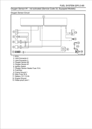
![3-86 FUEL SYSTEM (DFI)
Exhaust Butterfly Valve Actuator Sensor (Service Code 34)
Exhaust Butterfly Valve Actuator Sensor
Removal/Installation
The exhaust butterfly valve actuator sensor is built in the
exhaust butterfly valve actuator. So, the sensor itself can
not be removed. Remove the exhaust butterfly valve actu-
ator (see Exhaust Butterfly Valve Actuator Removal).
Exhaust Butterfly Valve Actuator Sensor Input
Voltage Inspection
NOTE
○Be sure the battery is fully charged.
• Turn the ignition switch OFF.
• Removechapter).side cover (see Side Cover Removal in
the Frame
the left
• Disconnect (3 pins connector) [A] and connect the har-
lead connector
the exhaust butterfly valve actuator sensor
ness adapter [B] between these connector.
Special Tool - Throttle Sensor Setting Adapter #1: 57001
-1400
• Connect a digital meter to the harness adapter leads.
Exhaust Butterfly Valve Actuator Sensor Input Voltage
Connections to Adapter:
Digital Meter (+) → Y/W (actuator W) lead
Digital Meter (−) → BK/BL (actuator BK) lead
• Measure the input voltage with the engine stopped and
with the connector joined.
• Turn the ignition switch ON.
Input Voltage
Standard: DC 4.75 ∼ 5.25 V
• Turn the ignition switch OFF.
If the reading is within the standard, check the output volt-
age (see Exhaust Butterfly Valve Actuator Sensor Output
Voltage Inspection).
If the reading is out of the standard, remove the ECU
and check the wiring for continuity between main harness
connectors.
○Disconnect the ECU and sensor connectors.
Special Tool - Hand Tester: 57001-1394
Wiring Continuity Inspection
ECU Connector (Black) [A] ←→
Exhaust Butterfly Valve Actuator Sensor Connector [B] BL
lead (ECU terminal 7) [C]
BR/BK lead (ECU terminal 34) [D]
If the wiring is good, check the ECU for its ground and
power supply (see ECU Power Supply Inspection).
If the ground and power supply are good, replace the ECU
(see ECU Removal/Installation).](https://image.slidesharecdn.com/2008-100321201635-phpapp01/85/2008-179-320.jpg)
![FUEL SYSTEM (DFI) 3-87
Exhaust Butterfly Valve Actuator Sensor (Service Code 34)
Exhaust Butterfly Valve Actuator Sensor Output
Voltage Inspection
NOTE
○Before this inspection, confirm the pulley [A] is original
position (see Exhaust Butterfly Valve Actuator Installa-
tion).
• Disconnect:
2 pins Connector [B]
3 pins Connector [C]
• nectors. the harness adapter [A] between the 3 pins con-
Connect
Special Tool - Throttle Sensor Setting Adapter #1: 57001
-1400
• Connect a digital meter to the harness adapter leads.
Exhaust Butterfly Valve Actuator Sensor Output Voltage
Connections to Adapter:
Digital Meter (+) → BL (actuator Y) lead
Digital Meter (−) → BK/BL (actuator BK) lead
• Measure the output voltage at the 3 pins connector of the
exhaust butterfly valve actuator when the pulley is original
position.
• Turn the ignition switch ON.
Output Voltage
Standard: DC 3.46 ∼ 3.76 V at pulley original position
• Turn the ignition switch OFF.
If the reading is out of the standard, check the exhaust
butterfly valve actuator sensor resistance (see Exhaust
Butterfly Valve Actuator Sensor Resistance Inspection).
If the reading is within the standard, remove the ECU and
check the wiring for continuity between main harness con-
nectors.
Special Tool - Hand Tester: 57001-1394
○Disconnect the ECU and sensor connectors.
Wiring Continuity Inspection
ECU Connector (Black) [A] ←→
Exhaust Butterfly Valve Actuator Sensor Connector [B] GY
lead (ECU terminal 10) [C]
BR/BK lead (ECU terminal 34) [D]
If the wiring is good, check the ECU for its ground and
power supply (see ECU Power Supply Inspection).
If the ground and power supply are good, replace the ECU
(see ECU Removal/Installation).](https://image.slidesharecdn.com/2008-100321201635-phpapp01/85/2008-180-320.jpg)
![3-88 FUEL SYSTEM (DFI)
Exhaust Butterfly Valve Actuator Sensor (Service Code 34)
Exhaust Butterfly Valve Actuator Sensor
Resistance Inspection
• Turn the ignition switch OFF.
• Disconnect the exhaust butterfly valve actuator sensor
connector (3 pins connector) [A].
• Connect a digital meter [B] to the exhaust butterfly valve
actuator sensor connector.
• Measure the exhaust butterfly valve actuator sensor
resistance.
Exhaust Butterfly Valve Actuator Sensor Resistance
Connections: W lead [C] ←→ BK lead [D]
Standard: 4 ∼ 6 kΩ
If the reading is out of the standard, replace the exhaust
butterfly valve actuator.
If the reading within the standard, but the problem still
exists, replace the ECU (see ECU Removal/Installation).
Exhaust Butterfly Valve Actuator Sensor Circuit
1. ECU
2. Joint Connector 4
3. Exhaust Butterfly Valve Actuator](https://image.slidesharecdn.com/2008-100321201635-phpapp01/85/2008-181-320.jpg)
![FUEL SYSTEM (DFI) 3-89
Immobilizer Amplifier (Service Code 35, Equipped Models)
Antenna Resistance Inspection
• Turn the ignition switch OFF.
• Remove the right upper inner fairing (see Upper Inner
Fairing Removal in the Frame chapter).
• Disconnect the antenna lead connector [A].
• Measure the antenna resistance.
Antenna Resistance
Connections: BK lead ←→ BK lead
Standard: About 0.6 ∼ 0.9 Ω
If the reading is out of the standard, replace the antenna
(see Immobilizer System Parts Replacement in the
Electrical System chapter).
If the reading is within the standard, check the wiring to
the amplifier (see wiring diagram in next section).
If the wiring is good, check the input voltage of the amplifier
(see Amplifier Input Voltage Inspection).
Amplifier Input Voltage Inspection
NOTE
○Be sure the battery is fully charged.
• Turn the ignition switch OFF.
• Removal in the Frame chapter).(see Upper Inner Fairing
Remove the right upper inner
• tectorout the immobilizer amplifier [A] with the rubber pro-
Pull
[B] from the bracket [C].
• needle adapter set. to the amplifier connector [D] with
Connect a digital meter
Special Tool - Needle Adapter Set: 57001-1457
Amplifier Input Voltage
Connections to Amplifier Connector:
Digital Meter (+) → BR/W lead
Digital Meter (-) → BK/Y lead
• with the connector joined. with the engine stopped and
Measure the input voltage
• Turn the ignition switch ON.
Input Voltage
Standard: Battery Voltage
• Turn the ignition switch OFF.
If the reading is out of the standard, check the wiring (see
wiring diagram in next section).
Special Tool - Hand Tester: 57001-1394
If the reading is within the standard, check the wiring to
ECU (see wiring diagram in next section).
Special Tool - Hand Tester: 57001-1394
If the wiring is good, replace the amplifier (see Immobi-
lizer System Parts Replacement in the Electrical System
chapter).](https://image.slidesharecdn.com/2008-100321201635-phpapp01/85/2008-182-320.jpg)
![3-90 FUEL SYSTEM (DFI)
Blank Key Detection (Service Code 36, Equipped Models)
• This code appears in the following conditions.
○The transponder [A] in the master and/or user key is
malfunction.
○When the spare key of unregistration is used.
○When the master key is registered in the registered ECU.
• Therefore,isthe service code 36 will disappear when the
above issue solved.
User Key Inspection
• Register the user key correctly (see Key Registration in
the Electrical System chapter).
If the service code 36 appears again, the transponder in
the key is malfunction, replace it.](https://image.slidesharecdn.com/2008-100321201635-phpapp01/85/2008-183-320.jpg)
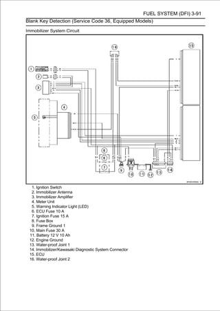
![3-92 FUEL SYSTEM (DFI)
ECU Communication Error (Service Code 39)
ECU Communication Line Inspection
○When the data is not sent from the ECU to the meter unit
for more than about 10 seconds, the service code 39 is
displayed.
○The service code 39 is detected with meter unit.
• Remove the ECU and meter unit, check the wiring for
continuity between main harness connectors.
Special Tool - Hand Tester: 57001-1394
○Disconnect the ECU and meter unit connectors.
Wiring Continuity Inspection
ECU Connector (Gray) [A] ←→
Meter Unit Connector [B]
BR/R lead (ECU terminal 36) [C]
If the wiring is good, check the meter unit (see Meter Unit
Inspection in the Electrical System chapter).
If the meter unit is normal, replace the ECU (see ECU
Removal/Installation).
ECU Communication Line Circuit
1. ECU
2. Meter Unit
3. Warning Indicator Light (LED)
4. Frame Ground 1](https://image.slidesharecdn.com/2008-100321201635-phpapp01/85/2008-185-320.jpg)
![FUEL SYSTEM (DFI) 3-93
Fuel Pump Relay (Service Code 46)
Fuel Pump Relay Removal/Installation
○The fuel pump relay is built in the relay box [A].
• Refer to the Relay Box Removal in the Electrical System
chapter.
Fuel Pump Relay Inspection
• Refer to the Relay Circuit Inspection in the Electrical System
chapter.
If the fuel pump relay is normal, check the wiring for
continuity (see wiring diagram in this section).
Special Tool - Hand Tester: 57001-1394
If the wiring is good, check the ECU for its ground and
power supply (see ECU Power Supply Inspection).
If the ground and power supply are good, replace the ECU
(see ECU Removal/Installation).
Fuel Pump Relay Circuit
1. ECU 9. Relay Box
2. Water-proof Joint 2 10. Frame Ground 1
3. Engine Stop Switch 11. Main Fuse 30 A
4. Ignition Switch 12. Battery 12 V 10 Ah
5. ECU Fuse 10 A 13. Engine Ground
6. Ignition Fuse 15 A 14. Fuel Pump
7. Fuse Box 15. Water-proof Joint 1
8. Fuel Pump Relay](https://image.slidesharecdn.com/2008-100321201635-phpapp01/85/2008-186-320.jpg)
![3-94 FUEL SYSTEM (DFI)
Stick Coils #1, #2, #3, #4 (Service Code 51, 52, 53, 54)
Stick Coil #1: Service Code 51
Stick Coil #2: Service Code 52
Stick Coil #3: Service Code 53
Stick Coil #4: Service Code 54
Stick Coil Removal/Installation
• Refer to the Stick Coil Removal/Installation in the Electrical
System chapter.
Stick Coil Primary Winding Resistance Inspection
• Refer to the Stick Coil Inspection in the Electrical System
chapter.
If the reading is within the standard, check the input voltage
(see Stick Coil Input Voltage Inspection).
Stick Coil Input Voltage Inspection
NOTE
○Be sure the battery is fully charged.
• Turn the ignition switch OFF.
• Remove the ECU (seeECU connectors.
○Do not disconnect the
ECU Removal).
• needle adapter set. [A] to the connector [B]
Connect a digital meter with the
Special Tool - Needle Adapter Set: 57001-1457
Stick Coil Input Voltage
Connections to ECU Connector:
For Stick Coil #1
Digital Meter (+) → BK lead (terminal 49)
Digital Meter (-) → Battery (-) terminal
For Stick Coil #2
Digital Meter (+) → BK/G lead (terminal 51)
Digital Meter (-) → Battery (-) terminal
For Stick Coil #3
Digital Meter (+) → BK/W lead (terminal 66)
Digital Meter (-) → Battery (-) terminal
For Stick Coil #4
Digital Meter (+) → BK/O lead (terminal 68)
Digital Meter (-) → Battery (-) terminal
• Measure the input voltage to each primary winding of the
stick coils with the engine stopped, and with the connectors
joined.
• Turn the engine stop switch to run position.
• Turn the ignition switch ON.
Input Voltage
Standard: Battery Voltage](https://image.slidesharecdn.com/2008-100321201635-phpapp01/85/2008-187-320.jpg)
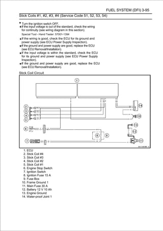
![3-96 FUEL SYSTEM (DFI)
Radiator Fan Relay (Service Code 56)
Radiator Fan Relay Removal/Installation
○The radiator fan relay is built in the relay box [A].
• Refer to the Relay Box Removal in the Electrical System
chapter.
Radiator Fan Relay Inspection
• Refer to the Relay Circuit Inspection in the Electrical System
chapter.
If the radiator fan relay is normal, check the wiring for
continuity (see wiring diagram in this section).
Special Tool - Hand Tester: 57001-1394
If the wiring is good, check the ECU for its ground and
power supply (see ECU Power Supply Inspection).
If the ground and power supply are good, replace the ECU
(see ECU Removal/Installation).](https://image.slidesharecdn.com/2008-100321201635-phpapp01/85/2008-189-320.jpg)
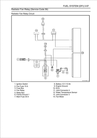
![3-98 FUEL SYSTEM (DFI)
Subthrottle Valve Actuator (Service Code 62)
Subthrottle Valve Actuator Removal
CAUTION
Do not remove the subthrottle valve actuator [A]
since it has been adjusted and set with precision at
the factory.
Never drop the throttle body assy, especially on a
hard surface. Such a shock to the subthrottle valve
actuator can damage it.
Subthrottle Valve Actuator Inspection
NOTE
○Be sure the battery is fully charged.
• Remove the upper air cleaner housing (see Air Cleaner
Housing Removal).
• Turn the ignition switch ON.
• Check to see that all the subthrottle valves [A] open and
close smoothly.
• Turn the ignition switch OFF.
If the subthrottle valves do not operate, check the sub-
throttle valve actuator resistance (see Subthrottle Valve
Actuator Resistance Inspection).
Subthrottle Valve Actuator Resistance Inspection
• Turn the ignition switch OFF.
• Remove the air cleaner housing (see Air Cleaner Housing
Removal).
• Cut the band [A], and disconnect the subthrottle valve
actuator connector [B].
• Connect[A]. digital meter to the subthrottle valve actuator
connector
a
• Measure the subthrottle valve actuator resistance.
Subthrottle Valve Actuator Resistance
Connections: Y/BK lead [1] ←→ P lead [2]
G lead [3] ←→ BK/BL lead [4]
Standard: About 6.3 ∼ 9.5 Ω
If the reading is out of the standard, replace the throttle
body assy.
If the reading is within the standard, check the input volt-
age (see Subthrottle Valve Actuator Input Voltage Inspec-
tion).](https://image.slidesharecdn.com/2008-100321201635-phpapp01/85/2008-191-320.jpg)
![FUEL SYSTEM (DFI) 3-99
Subthrottle Valve Actuator (Service Code 62)
Subthrottle Valve Actuator Input Voltage
Inspection
NOTE
○Be sure the battery is fully charged.
• Turn the ignition switch OFF.
• connect the harness adapter [A] between these connec-
Disconnect the subthrottle valve actuator connector and
tors as shown in the figure.
Main Harness [B]
Subthrottle Valve Actuator [C]
Special Tool - Measuring Adapter: 57001-1700
• [E] to the the peak adapter adapter [D] and a digital meter
Connect
harness
voltage
leads.
Special Tool - Peak Voltage Adapter: 57001-1415
Type: KEK-54-9-B
Subthrottle Valve Actuator Input Voltage
Connections to Adapter:
(I) Digital Meter (+) → R (actuator BK/BL) lead
Digital Meter (-) → Battery (-) terminal
(II) Digital Meter (+) → BK (actuator G) lead
Digital Meter (-) → Battery (-) terminal
(III) Digital Meter (+) → W (actuator P) lead
Digital Meter (-) → Battery (-) terminal
(IV) Digital Meter (+) → Y (actuator Y/BK) lead
Digital Meter (-) → Battery (-) terminal
• stopped and with the connectorvoltage
Measure the actuator input
joined.
with the engine
• Turn the ignition switch ON.
Input Voltage
Standard: About DC 8.5 ∼ 10.5 V, and then 0 V
• Turn the ignition switch OFF.
If the reading is in specification, but the actuator does not
operate, replace the throttle body assy.
If the reading is out of the specification, remove the ECU
and check the wiring for continuity between main harness
connector.
Special Tool - Hand Tester: 57001-1394
○Disconnect the ECU and actuator connectors.
Wiring Continuity Inspection
ECU Connector (Black) [A] ←→
Subthrottle Valve Actuator Connector [B]
G lead (ECU terminal 2) [C]
BK/BL lead (ECU terminal 3) [D]
Y/BK lead (ECU terminal 19) [E]
P lead (ECU terminal 20) [F]
If the wiring is good, check the ECU for its ground and
power supply (see ECU Power Supply Inspection).
If the ground and power supply are good, replace the ECU
(see ECU Removal/Installation).](https://image.slidesharecdn.com/2008-100321201635-phpapp01/85/2008-192-320.jpg)
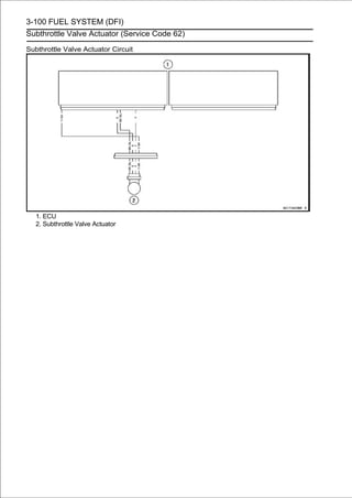
![FUEL SYSTEM (DFI) 3-101
Exhaust Butterfly Valve Actuator (Service Code 63)
Exhaust Butterfly Valve Actuator Removal
CAUTION
Never drop the exhaust butterfly valve actuator,
especially on a hard surface. Such a shock to the
actuator can damage it.
• Remove:
Exhaust Butterfly Valve Cable Upper Ends (see Exhaust
Butterfly Valve Cable Removal in the Engine Top End
chapter)
Connectors [A]
Screws [B]
Exhaust Butterfly Valve Actuator [C]
• Remove the pulley bolt while holding the pulley [A] with
the suitable tool [B].
CAUTION
If the pulley bolt is removed without holding, the
actuator damage will occur.
• Remove the pulley from the actuator.
Exhaust Butterfly Valve Actuator Installation
• Install the pulley [A] on the actuator so that the hole side
[B] align with the groove [C] on the shaft.
• Tighten the pulley bolt [A] while holding the pulley with the
suitable tool [B].
Torque - Exhaust Butterfly Valve Actuator Pulley Bolt: 5.0
N·m (0.51 kgf·m, 44 in·lb)
CAUTION
If the pulley bolt is tightened without holding, the
actuator damage will occur.](https://image.slidesharecdn.com/2008-100321201635-phpapp01/85/2008-194-320.jpg)
![3-102 FUEL SYSTEM (DFI)
Exhaust Butterfly Valve Actuator (Service Code 63)
• After tightening the pulley bolt, confirm whether pulley [A] is
an angle shown in the figure.
41.7° ±7° [B]
○This position is original position of the pulley.
NOTE
○Correct the position electrically after confirming the use is
discontinued and there is no damage when differing from
the angle of shown in the figure.
CAUTION
Do not correct the pulley position with the tool,
forcibly. The actuator damage will occur.
If the pulley angle is wrong, adjust the angle as follows.
○Connect:
2 pins Connector
3 pins Connector
○Turn the ignition switch ON.
○The pulley turns clockwise and then counterclockwise,
and clockwise again.
○Turn the ignition switch OFF.
○Confirm that the pulley turns counterclockwise and the
pulley returns to the original position.
If the position is not within the specified angle above,
replace the exhaust butterfly valve actuator.
• Be actuator install the washers fronton the exhaust butterfly
valve
sure to
[B] and rear fender
[A]
[C].
• Tighten:
Torque - Exhaust Butterfly Valve Actuator Mounting
Screws [D]: 4.3 N ·m (0.44 kgf ·m, 38 in·lb)
• Install adjust themends Exhaust Butterfly Valve Cable ca-
bles and
the upper
(see
of the exhaust butterfly valve
Installation in the Engine Top End chapter).](https://image.slidesharecdn.com/2008-100321201635-phpapp01/85/2008-195-320.jpg)
![FUEL SYSTEM (DFI) 3-103
Exhaust Butterfly Valve Actuator (Service Code 63)
Exhaust Butterfly Valve Actuator Inspection
NOTE
○Be sure the battery is fully charged
• Remove the front seat (see Front Seat Removal in the
Frame chapter).
• Turn the ignition switch ON.
• Check to see[C]the pulley [A] turns clockwise [B] and
counterclockwise smoothly.
○The pulley turns clockwise and then counterclockwise,
and clockwise again.
• Turn the ignition switch OFF.
○The pulley turns counterclockwise.
If the pulley does not operate, check the exhaust butterfly
valve actuator resistance (see Exhaust Butterfly Valve
Actuator Inspection Resistance Inspection).
Exhaust Butterfly Valve Actuator Resistance
Inspection
• Turn the ignition switch OFF.
• Disconnect the exhaust butterfly valve actuator lead
connector (2 pins connector) [A].
• Set the hand tester to the × 1 Ω range and connect it to
the exhaust butterfly valve actuator connector.
Special Tool - Hand Tester: 57001-1394
• Measure the exhaust butterfly valve actuator resistance.
Exhaust Butterfly Valve Actuator Resistance
Connections: P lead ←→ GY lead
Standard: Any Reading Resistance (reference
5 ∼200Ω)
If the reading is 0 or infinity (∞) Ω, replace the exhaust
butterfly valve actuator.
If the reading is in specification, remove the ECU and
check the wiring for continuity between main harness con-
nectors.
Special Tool - Hand Tester: 57001-1394
○Disconnect the ECU and actuator connectors.
Wiring Continuity Inspection
ECU Connector (Gray) [A] ←→
Exhaust Butterfly Valve Actuator Connector [B] W/R
lead (ECU terminal 43) [C]
W/BL lead (ECU terminal 45) [D]
If the wiring is good, check the ECU for its ground and
power supply (see ECU Power Supply Inspection).
If the ground and power supply are good, replace the ECU
(see ECU Removal/Installation).](https://image.slidesharecdn.com/2008-100321201635-phpapp01/85/2008-196-320.jpg)
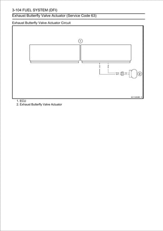
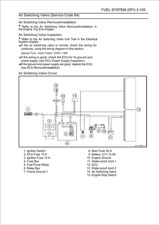
![3-106 FUEL SYSTEM (DFI)
Oxygen Sensor Heater #1 and/or #2 (Service Code 67, Equipped Models)
Oxygen Sensor Heater Removal/Installation
The oxygen sensor heater is built in the oxygen sensor.
So, the heater itself can not be removed. Remove the oxygen
sensor (see Oxygen Sensor Removal (Equipped Models) in
the Electrical System chapter).
Oxygen Sensor Heater Resistance Inspection
•Turn the ignition switch OFF.
•Disconnect:
Oxygen Sensor #1 Lead Connector (Gray) [A]
Oxygen Sensor #2 Lead Connector (Black) [B]
• Connect a digital meter [A] to the terminals in each oxygen
sensor lead connector [B].
• Measure the oxygen sensor heater resistance.
Oxygen Sensor Heater #1 and #2 Resistance
Connections: W lead [C] ←→ W lead [D]
Standard: 6.7 ∼ 10.5 Ω at 20° (68°F)
If the reading is out of the standard, replace the sensor.
If the reading is within the standard, check the power
source voltage (see Oxygen Sensor Heater Power
Source Voltage Inspection).](https://image.slidesharecdn.com/2008-100321201635-phpapp01/85/2008-199-320.jpg)
![FUEL SYSTEM (DFI) 3-107
Oxygen Sensor Heater #1 and/or #2 (Service Code 67, Equipped Models)
Oxygen Sensor Heater Power Source Voltage
Inspection
NOTE
○Be sure the battery is fully charged.
• Turn the ignition switch OFF.
• and connectthe oxygen sensor #1 [A] between connectors
Disconnect
the harness adapter
and #2 lead
these con-
nectors as shown in the figure.
Main Harness [B]
Oxygen Sensor #1 [C]
Oxygen Sensor #2 [D]
Special Tool - Measuring Adapter: 57001-1700
• Connect a digital meter [E] to the harness adapter leads.
Oxygen Sensor Heater #1 and #2 Power Source Voltage
Connections to Adapter:
Digital Meter (+) → R (main harness LG) lead
Digital Meter (-) → Battery (-) terminal
• stopped and with the connectorvoltage with
Measure the power source
joined.
the engine
• Turn the ignition switch ON.
Power Source Voltage
Standard: Battery Voltage
• Turn the ignition switch OFF.
If the reading is in specification, but the problem still ex-
ists, replace the ECU (see ECU Removal/Installation).
If the reading is out of the standard, check the following.
Oxygen Sensor Heater Fuse 10 A (see Fuse Inspection
in the Electrical System chapter)
Power Source Wiring (see wiring diagram in this section)
If the fuse and wiring are good, remove the ECU and
check the wiring for continuity between main harness con-
nectors.
Special Tool - Hand Tester: 57001-1394
○Disconnect the ECU and sensor connectors.
Wiring Continuity Inspection
ECU Connector (Gray) [A] ←→
Oxygen Sensor #1 and #2 Connectors [B]
R lead (ECU terminal 50) [C]
If the wiring is good, check the ECU for its ground and
power supply (see ECU Power Supply Inspection).
If the ground and power supply are good, replace the ECU
(see ECU Removal/Installation).](https://image.slidesharecdn.com/2008-100321201635-phpapp01/85/2008-200-320.jpg)
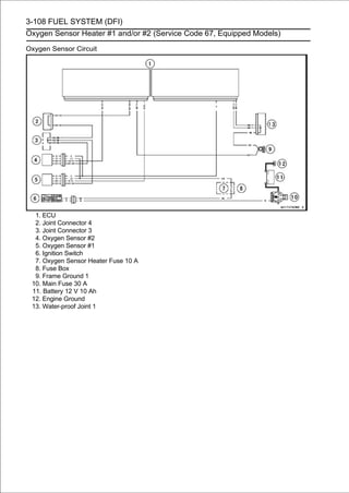
![FUEL SYSTEM (DFI) 3-109
Oxygen Sensor #2 - not activated (Service Code 83, Equipped Models)
Oxygen Sensor #2 Removal/Installation
• Refer to the Oxygen Sensor Removal/Installation
(Equipped Models) in the Electrical System chapter.
Oxygen Sensor #2 Inspection
• Warm up the engine thoroughly until the radiator fan
starts.
• Turn the ignition switch OFF.
• Remove:
Middle Air Cleaner Housing (see Air Cleaner Housing
Removal)
Primary Fuel Hose (see Fuel Hose Replacement in the
Periodic Maintenance chapter)
Oxygen Sensor #2 Lead Connector (Black) [A]
• Connect the and oxygen sensor[A] between the main har-
ness connector
harness adapter
#2 lead connector as
shown in the figure.
Main Harness [B]
Oxygen Sensor #2 [C]
Special Tool - Measuring Adapter: 57001-1700
• Connect a digital meter [D] to the harness adapter leads.
Oxygen Sensor #2 Output Voltage
Connections to Adapter:
Digital Meter (+) → R (sensor BK) lead
Digital Meter (−) → BK (sensor GY) lead
• Separate the air switching air cleaner housing. the air
suction valve covers and lower
valve hoses [A] from
○Do not disconnect the air switching valve connector [B].](https://image.slidesharecdn.com/2008-100321201635-phpapp01/85/2008-202-320.jpg)
![3-110 FUEL SYSTEM (DFI)
Oxygen Sensor #2 - not activated (Service Code 83, Equipped Models)
• Install the suitable plugs [A] on the fitting of the air suction
valve covers, and shut off the secondary air.
• Connect the Lead Connector [A]
Fuel Pump
following parts temporarily.
Extension Tube [B]
Special Tool - Extension Tube: 57001-1578
• Connect the following parts temporarily.
Inlet Air Temperature Sensor Connector [A]
Secondary Fuel Hose [B] (see Fuel Hose Replacement)
NOTE
○Be sure to connect the inlet air temperature sensor con-
nector. When the ignition switch is turned ON with in-
let air temperature sensor connector disconnected, the
ECU detects the service code 13. Then the ECU starts
the fail-safe (see Self-diagnosis Outline in the Fuel Sys-
tem (DFI) chapter). In this case, the engine vacuum
synchronization can not be inspected correctly.
○Do not connect the secondary fuel injector connectors.
The engine vacuum synchronization is inspected with
the air cleaner housing removed and the engine started.
The secondary fuel injectors are operating with following
conditions.
1. The engine speed is more than 6 000 r/min (rpm).
2. The throttle opening is more than 30°.
WARNING
Gasoline is extremely flammable and can be explo-
sive under certain condition. Especially, the gaso-
line jetted from the secondary fuel injector is ex-
tremely flammable for atomizing the gasoline by the
injector.
• Start the engine, and let it idle.
• Measure the output voltage with the connector joined.
Output Voltage (with Plugs)
Standard: DC 0.8 V or more](https://image.slidesharecdn.com/2008-100321201635-phpapp01/85/2008-203-320.jpg)
![FUEL SYSTEM (DFI) 3-111
Oxygen Sensor #2 - not activated (Service Code 83, Equipped Models)
• Next, remove the plugs from the fittings [A] with idling.
• Measure the output voltage with the connector joined.
Output Voltage (without Plugs)
Standard: DC 0.24 V or less
• Turn the ignition switch OFF.
If the reading is out of the standard (with plugs: 0.8 V
or more, without plugs: 0.24 V or less), remove the ECU
and check the wiring for continuity between main harness
connectors.
Special Tool - Hand Tester: 57001-1394
○Disconnect the ECU and sensor connectors.
Wiring Continuity Inspection
ECU Connector (Black) [A] ←→
Oxygen Sensor #2 Connector [B]
BR/W lead (ECU terminal 22) [C]
BR/BK lead (ECU terminal 34) [D]
If the wiring is good, replace the sensor.
If the reading is within the standard (with plugs: 0.8 V
or more, without plugs: 0.24 V or less), check the ECU
for its ground and power supply (see ECU Power Supply
Inspection).
If the ground and power supply are good, replace the ECU
(see ECU Removal/Installation).](https://image.slidesharecdn.com/2008-100321201635-phpapp01/85/2008-204-320.jpg)
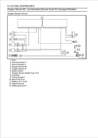
![FUEL SYSTEM (DFI) 3-113
Warning Indicator Light (LED)
Light (LED) Inspection
○The warning indicator light (LED) [A] is used for the FI
indicator, immobilizer indicator (equipped models) and oil
pressure warning indicator.
○In this model, the warning indicator light (LED) (FI/immo-
bilizer) blinks by the data sent from the ECU.
• Refer to the Meter Unit Inspection in the Electrical System
chapter.
Warning Indicator Light (LED) (FI/Immobilizer) Circuit
1. ECU
2. Meter Unit
3. Warning Indicator Light (LED)
4. Frame Ground 1](https://image.slidesharecdn.com/2008-100321201635-phpapp01/85/2008-206-320.jpg)
![3-114 FUEL SYSTEM (DFI)
ECU
ECU Identification
○Most countries have their own regulations, so each ECU
has different characteristic. So, do not confuse ECU with
each other and use only the ECU for your model. Other-
wise, the motorcycle can not clear the regulation.
ECU Identification
Part Number [A] Specification
WVTA (FULL H), with Immobilizer
21175-0158
GB WVTA (FULL H), with Immobilizer
21175-0163 US, without Immobilizer
CA, without Immobilizer
21175-0164 CAL, without Immobilizer
21175-0188 AU, with Immobilizer
21175-0189 MY, with Immobilizer
21175-0190 WVTA (78.2 H), with Immobilizer
21175-0192 SEA, with Immobilizer
ECU Removal
CAUTION
Never drop the ECU, especially on a hard surface.
Such a shock to the ECU can damage it.
• Remove chapter). seat cover (see Seat Cover Removal in
the Frame
the center
• Pull protector. box [A] and turn signal relay [B] from the
rubber
out the relay
○Do not disconnect the relay box connectors and turn signal
relay connector.
• Lift up the ECU [A] with rubber protector [B] to clear the
projections [C].
• Remove:
ECU Connectors [A]
ECU [B] (with Rubber Protector [C])](https://image.slidesharecdn.com/2008-100321201635-phpapp01/85/2008-207-320.jpg)
![FUEL SYSTEM (DFI) 3-115
ECU
ECU Installation
•Install:
ECU [A] (in Rubber Protector [B])
ECU Connectors [C]
• Insert thefenderoffront.rubber protector [A] to the projections [B]
of the rear
slits the
ECU Power Supply Inspection
• Remove the center seat cover (see Seat Cover Removal
in the Frame chapter).
• Visually inspect the ECU connectors.or dust, blow it off
If the connector is clogged with mud
with compressed air.
• Remove the ECU (see ECU Removal).
• Visually inspectofthe terminals [A] ofconnectors are dam-
If the terminals the main harness
the ECU connectors.
aged, replace the main harness.
If the terminals of the ECU connectors are damaged, re-
place the ECU.
• Turn the ignition switch OFF.
• Disconnect the ECU connectors [A].
• Set the hand testercontinuity.× 1 Ω range and check the
following wiring for
[B] to the
Special Tool - Hand Tester: 57001-1394
ECU Grounding Inspection
Connections:
(I) BK/Y leads (ECU
terminal 17, 41 or 58)
←→ Battery (-) Terminal
(II) Engine Ground
Criteria: ←→ Battery (-) Terminal
Both: 0 Ω
If no continuity, check the connectors, the engine ground
lead, or main harness, and repair or replace them if nec-
essary.](https://image.slidesharecdn.com/2008-100321201635-phpapp01/85/2008-208-320.jpg)
![3-116 FUEL SYSTEM (DFI)
ECU
If the wiring is good, check the power source voltage of
the ECU.
NOTE
○Be sure the battery is fully charged.
• Connect the ECU connectors.
• Connect a digital meter [A] to the connector [B] with the
needle adapter set.
Special Tool - Needle Adapter Set: 57001-1457
ECU Power Supply Inspection
Connections:
(I) Digital Meter (+) → Terminal 15 (W/BK)
Digital Meter (-) → Battery (-) terminal
(II) Digital Meter (+) → Terminal 24 (BR)
Digital Meter (-) → Battery (-) terminal
(III) Digital Meter (+) → Terminal 32 (W/BK)
Digital Meter (-) → Battery (-) terminal
Ignition Switch OFF:
Terminal 15 (W/BK): Battery Voltage
Terminal 24 (BR): 0 V
Terminal 32 (W/BK): Battery Voltage
Ignition Switch ON:
All: Battery Voltage
If the reading is out of the specification, check the follow-
ing.
Main Fuse 30 A (see Fuse Inspection in the Electrical
System chapter)
ECU Fuse 10 A (see ECU Fuse Inspection Electrical
System chapter)
Power Source Wiring (see wiring diagram in this sec-
tion )
If the fuse and wiring are good, replace the ECU (see ECU
Removal/Installation).](https://image.slidesharecdn.com/2008-100321201635-phpapp01/85/2008-209-320.jpg)
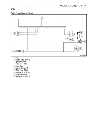
![3-118 FUEL SYSTEM (DFI)
DFI Power Source
ECU Fuse Removal
• Refer to the 10 A ECU Fuse Removal in the Electrical
System chapter.
ECU Fuse Installation
If a fuse fails during operation, inspect the DFI system to
determine the cause, and then replace it with a new fuse of
proper amperage.
• Refer to the Fuse Installation in the Electrical System
chapter.
ECU Fuse Inspection
• Refer to the Fuse Inspection in the Electrical System
chapter.
ECU Main Relay Removal/Installation
○The ECU main relay function is included in the ECU [A]
and can not be removed.
ECU Main Relay Inspection
○The ECU main relay function is included in the ECU [A]
and can not be inspected.](https://image.slidesharecdn.com/2008-100321201635-phpapp01/85/2008-211-320.jpg)
![FUEL SYSTEM (DFI) 3-119
Fuel Line
Fuel Pressure Inspection
NOTE
○Be sure the battery is fully charged.
• Remove:
Fuel Tank Bolts [A]
Primary Fuel Hose (see Fuel Hose Replacement in the
Periodic Maintenance chapter)
○Be sure to place a piece of cloth around the fuel outlet
pipe of the fuel pump and the delivery pipe of the throttle
body assy.
WARNING
Be prepared for fuel spillage; any spilled fuel must be
completely wiped up immediately.
When the fuel hose is disconnected, fuel spills out
from the hose and the pipe because of residual
pressure. Cover the hose connection with a piece of
clean cloth to prevent fuel spillage.
• Install the fuel pressure gauge adapter [A]the fuel outlet
(Special Tool: 57001-1607) [B] between
and fuel hoses
pipe and delivery pipe.
• Secure the fuel hoses with the clamps.
• Connect the pressure gauge [C] to the fuel pressure
gauge adapter.
Special Tools - Oil Pressure Gauge, 5 kgf/cm²: 57001-125
Fuel Pressure Gauge Adapter: 57001-1593
Fuel Hose: 57001-1607
WARNING
Do not try to start the engine with the fuel hoses
disconnected.
• Turn the engine stop switch run position.
• Turn fuel ignitionshould operate for 3 seconds, and then
the
○The pump
switch ON.
should stop.
NOTE
○After turning on the engine stop switch and ignition
switch, inspect the fuel leakage from the connected
portion of the special tools.
CAUTION
Do not drive the fuel pump 3 seconds or more without
the fuel in the fuel tank. If the fuel pump is driven
without the fuel, it may be damaged.
• Start the engine, and let it idle.
• Measure the fuel pressure with the engine idling.
Fuel Pressure (with Engine Idling)
Standard: 294 kPa (3.0 kgf/cm², 43 psi)](https://image.slidesharecdn.com/2008-100321201635-phpapp01/85/2008-212-320.jpg)
![3-120 FUEL SYSTEM (DFI)
Fuel Line
NOTE
○The gauge needle will fluctuate. Read the pressure at
the average of the maximum and minimum indications.
• Turn the ignition switch OFF.
If the fuel pressure is much higher than specified, replace
the fuel pump because the fuel pressure regulator in the
fuel pump have been clogged or stuck.
If the fuel pressure is much lower than specified, check
the following.
Fuel Line Leakage (see Fuel Injector Fuel Line Inspec-
tion)
Amount of Fuel Flow (see Fuel Flow Rate Inspection)
• After above checks, measure the fuel pressure again.
• Remove the fuel pressure gauge, hoses and adapter.
• Install:
Primary Fuel Hose (see Fuel Hose Replacement in the
Periodic Maintenance chapter)
Fuel Tank (see Fuel Tank Installation)
• Start the engine and check for fuel leakage.
Fuel Flow Rate Inspection
WARNING
Gasoline is extremely flammable and can be explo-
sive under certain conditions. Make sure the area
is well-ventilated and free from any source of flame
or sparks; this includes any appliance with a pilot
light. Do not smoke. Turn the ignition switch OFF.
Be prepared for fuel spillage; any spilled fuel must
be completely wiped up immediately.
NOTE
○Be sure the battery is fully charged.
• Turn the ignition switch OFF.
• Wait until the engine cools down.
• measuring fuel hose (Special Tool:
Prepare a
cylinder.
57001-1607) and a
Special Tool - Fuel Hose: 57001-1607
• Remove the fuel tank bolts [A].
• Open the fuel tank cap [A] to lower the pressure in the
tank.
• RemoveRemoval). fuel hose from the fuel pump (see
Fuel Tank
the primary
○Be sure to place a piece of cloth around the fuel outlet
pipe of the fuel pump.
WARNING
Be prepared for fuel spillage; any spilled fuel must be
completely wiped up immediately.
When the fuel hose is disconnected, fuel spills out
from the hose and the pipe because of residual
pressure. Cover the hose connection with a piece of
clean cloth to prevent fuel spillage.](https://image.slidesharecdn.com/2008-100321201635-phpapp01/85/2008-213-320.jpg)
![FUEL SYSTEM (DFI) 3-121
Fuel Line
• Connect the prepared fuel hose [A] to the fuel outlet pipe.
• Secure the fuel hose with a clamp.
• Insert the fuel hose into the measuring cylinder [B].
WARNING
Wipe off spilled out fuel immediately.
Be sure to hold the measuring cylinder vertical.
• Close the fuel tank cap.
• Turn the engine stop switch to run position.
• Turn the ignition switch ON.
○The fuel pump should operate for 3 seconds, and then
should stop.
CAUTION
Do not drive the fuel pump 3 seconds or more without
the fuel in the fuel tank. If the fuel pump is driven
without the fuel, it may be damaged.
• Measure theoperation severalseconds.
○Repeat this
discharge for 3
times.
Amount of Fuel Flow
Standard: 67 mL (2.3 US oz.) or more for 3 seconds
• Turn the ignition switch OFF.
If the fuel flow is much less than the specified, replace the
fuel pump (see Fuel Pump Removal/Installation).
• Install the fuel tank (see Fuel Tank Installation).
• Start the engine and check for fuel leakage.](https://image.slidesharecdn.com/2008-100321201635-phpapp01/85/2008-214-320.jpg)
![3-122 FUEL SYSTEM (DFI)
Fuel Pump
Fuel Pump Removal
WARNING
Gasoline is extremely flammable and can be explo-
sive under certain conditions. Make sure the area
is well-ventilated and free from any source of flame
or sparks; this includes any appliance with a pilot
light. Do not smoke. Turn the ignition switch OFF
and disconnect the battery (-) terminal.
To make fuel spillage minimum, draw the fuel out
from the fuel tank when the engine is cold. Be
prepared for fuel spillage; any spilled fuel must be
completely wiped up immediately.
CAUTION
Never drop the fuel pump, especially on a hard sur-
face. Such a shock to the pump can damage it.
• Draw the fuel out from the fuel tank with a commercially
available electric pump.
• Remove the fuel tank (see Fuel Tank Removal).
○Be careful of fuel spillage from the fuel tank since fuel still
remains in the fuel tank and fuel pump. Plug the fuel pipe of
the fuel tank.
• Turn the fuel tank upside down.
• Unscrew the fuel pump bolts [A], and take out the fuel
pump [B].
CAUTION
Do not pull the leads of the fuel pump. If they are
pulled, the lead terminals may be damaged.
• Discard the fuel pump gasket [A].](https://image.slidesharecdn.com/2008-100321201635-phpapp01/85/2008-215-320.jpg)
![FUEL SYSTEM (DFI) 3-123
Fuel Pump
Fuel Pump Installation
• Remove dirt or dust from the fuel pump [A] by lightly
applying compressed air.
• Replace the fuel pump gasket with a new one.
• Check that the fuel pump terminal [A] and band [B] are in
place.
Front [C]
• Apply a non-permanent locking agent to the threads of
the fuel pump bolts.
• Tighten the fuel pump bolts to a snug fit, following the
tightening sequence as shown in the figure.
• Following the tightening sequence, tighten the fuel pump
bolts to the specified torque.
Torque - Fuel Pump Bolts: 10 N·m (1.0 kgf·m, 89 in·lb)
• Tighten the pump bolts again to check the tightness in the
order shown.
Fuel Pump Operation Inspection
NOTE
○Be sure the battery is fully charged.
• Turn the engine stop switch to run position.
• Turnoperates (make light ON and makeseconds, and fuel
pump
the ignition switch
sounds) for 3
sure that the
then stops.
• Turn the ignition switch OFF.
If the pump does not operate as described above, check
the operating voltage (see Fuel Pump Operating Voltage
Inspection).](https://image.slidesharecdn.com/2008-100321201635-phpapp01/85/2008-216-320.jpg)
![3-124 FUEL SYSTEM (DFI)
Fuel Pump
Fuel Pump Operating Voltage Inspection
NOTE
○Be sure the battery is fully charged.
• Turn the ignition switch OFF.
• Removechapter).side cover (see Side Cover Removal in
the Frame
the left
• Disconnect the fuel pump theseconnector and shown the
harness adapter [A] between
lead
connectors as
connect
in the figure.
Main Harness [B]
Fuel Pump [C]
Special Tool - Measuring Adapter: 57001-1700
• Connect a digital meter [D] to the harness adapter leads.
Fuel Pump Operating Voltage
Connections to Adapter:
Digital Meter (+) → R (pump Y/R) lead
Digital Meter (-) → BK (pump BK/W) lead
• Measure the operating voltage with engine stopped and
with the connector joined.
• Turn the engine stop switch run position.
• Turn the ignition switch ON.
Operating Voltage
Standard: Battery Voltage for 3 seconds, and then 0 V
• Turn the ignition switch OFF.
If the reading stays on battery voltage and never shows 0
V, check the fuel pump relay (see Relay Circuit Inspection in
the Electrical System chapter).
If the fuel pump relay is normal, check the ECU for its
ground and power supply (see ECU Power Supply In-
spection).
If the ground and power supply are good, replace the ECU
(see ECU Removal/Installation).
If there is still no battery voltage, check the fuel pump re-
lay (see Relay Circuit Inspection in the Electrical System
chapter).
If the fuel pump relay is normal, check the wiring for
continuity (see wiring diagram in this section).
Special Tool - Hand Tester: 57001-1394
If the wiring is good, check the ECU for its ground and
power supply (see ECU Power Supply Inspection).
If the ground and power supply are good, replace the ECU
(see ECU Removal/Installation).
If the reading is in specification, but the pump does not op-
erate, replace the fuel pump (see Fuel Pump Removal/In-
stallation).](https://image.slidesharecdn.com/2008-100321201635-phpapp01/85/2008-217-320.jpg)
![FUEL SYSTEM (DFI) 3-125
Fuel Pump
Pressure Regulator Removal
○The pressure regulator [A] is built into the fuel pump and
can not be removed.
Fuel Filter Cleaning
○The fuel filter [A] is built into the pump and can not be
cleaned or checked.
If the pump screen or fuel filter is suspected of clogging
or being damaged, replace it with the fuel pump as a set.
Fuel Pump Circuit
1. ECU 8. Fuel Pump Relay
2. Water-proof Joint 2 9. Relay Box
3. Engine Stop Switch 10. Frame Ground 1
4. Ignition Switch 11. Main Fuse 30 A
5. ECU Fuse 10 A 12. Battery 12 V 10 Ah
6. Ignition Fuse 15 A 13. Engine Ground
7. Fuse Box 14. Fuel Pump
15. Water-proof Joint 1](https://image.slidesharecdn.com/2008-100321201635-phpapp01/85/2008-218-320.jpg)
![3-126 FUEL SYSTEM (DFI)
Fuel Injectors
Primary Fuel Injector Removal/Installation
• Refer to the Throttle Body Assy Disassembly/Assembly.
Secondary Fuel Injector Removal/Installation
• Refer to the Nozzle Assy Disassembly/Assembly.
Fuel Injector Audible Inspection
NOTE
○Be sure the battery is fully charged.
○The secondary fuel injectors are operating with following
conditions.
1. The engine speed is more than 6 000 r/min (rpm).
2. The throttle opening is more than 30°.
• Remove:
Fuel Tank (see Fuel Tank Removal)
Primary Fuel Hose (see Fuel Hose Replacement in the
Periodic Maintenance chapter)
• Connect the following parts temporarily.
Fuel Pump Lead Connector [A]
Extension Tube [B]
Special Tool - Extension Tube: 57001-1578
• Start the engine, and let it idle.
• Apply end onto your ear, and listento the fuel injector. Put
the grip
the tip of a screwdriver [A]
whether the fuel
injector is clicking or not.
Primary Fuel Injector [B]
Secondary Fuel Injector [C]
○A sound scope can also be used.
○The click interval becomes shorter as the engine speed
rises.
• Do the same for the other fuel injectors.
If all the fuel injectors click at a regular intervals, the fuel
injectors are normal.
• Turn the ignition switch OFF.
If any fuel injector does not click, check the fuel injector
resistance (see Fuel Injector Resistance Inspection).](https://image.slidesharecdn.com/2008-100321201635-phpapp01/85/2008-219-320.jpg)
![FUEL SYSTEM (DFI) 3-127
Fuel Injectors
Fuel Injector Resistance Inspection
For Primary Fuel Injectors
• Remove the air cleaner housing (see Air Cleaner Housing
Removal).
•Disconnect the primary fuel injector connector [A].
• Connect a digital meter to the terminals in each primary
fuel injector [A].
• Measure the primary fuel injector resistance.
Primary Fuel Injector Resistance
Standard: About 11.7 ∼ 12.3 Ω at 20°C (68°F)
If the reading is out of the standard, replace the primary
fuel injector.
If the reading within the standard, check the power source
voltage (see Fuel Injector Power Source Voltage Inspec-
tion).
For Secondary Fuel Injectors
• Remove the fuel tank (see Fuel Tank Removal).
• Disconnect the secondary fuel injector connector [A].
• Connect a digital meter to the terminals in each secondary fuel
injector [A].
• Measure the secondary fuel injector resistance.
Secondary Fuel Injector Resistance
Standard: About 10.5 Ω at 20°C (68°F)
If the reading is out of the standard, replace the secondary fuel
injector.
If the reading within the standard, check the power source
voltage (see Fuel Injector Power Source Voltage Inspec-
tion).](https://image.slidesharecdn.com/2008-100321201635-phpapp01/85/2008-220-320.jpg)
![3-128 FUEL SYSTEM (DFI)
Fuel Injectors
Fuel Injector Power Source Voltage Inspection
NOTE
○Be sure the battery is fully charged.
• Turn the ignition switch OFF.
For Primary Fuel Injectors
• Remove the air cleaner housing (see Air Cleaner Housing
Removal).
• Disconnect[A] between these connectors connect the har-
ness adapter
the injector connector and
as shown in
the figure.
Main Harness [B]
Primary Fuel Injector #1 [C]
Special Tool - Measuring Adapter: 57001-1700
• Connect a digital meter [D] to the harness adapter lead.
Primary Fuel Injector Power Source Voltage
Connections to Adapter:
For Primary Fuel Injector #1, #2, #3, #4
Digital Meter (+) → R (injector W/R) lead
Digital Meter (-) → Battery (-) terminal
• Measure the power source voltage with
stopped.
the engine
• Turn the engine stop switch to run position.
• Turn the ignition switch ON.
Power Source Voltage
Standard: Battery Voltage for 3 seconds, and then 0 V
• Turn the ignition switch OFF.
If the reading stays on battery voltage and never shows 0
V, check the fuel pump relay (see Relay Circuit Inspection in
the Electrical System chapter).
If the fuel pump relay is normal, check the ECU for its
ground and power supply (see ECU Power Supply In-
spection).
If the ground and power supply are good, replace the ECU
(see ECU Removal/Installation).
If there is still no battery voltage, check the fuel pump re-
lay (see Relay Circuit Inspection in the Electrical System
chapter).
If the fuel pump relay is normal, check the power source
wiring (see wiring diagram in this section).
Special Tool - Hand Tester: 57001-1394
If the wiring is good, check the ECU for its ground and
power supply (see ECU Power Supply Inspection).
If the ground and power supply are good, replace the ECU
(see ECU Removal/Installation).
If the reading is in specification, check the output voltage
(see Fuel Injector Output Voltage Inspection).](https://image.slidesharecdn.com/2008-100321201635-phpapp01/85/2008-221-320.jpg)
![FUEL SYSTEM (DFI) 3-129
Fuel Injectors
For Secondary Fuel Injectors
• Remove the fuel tank (see Fuel Tank Removal).
• Disconnect the injector connector and connectshown in
ness adapter [A] between these connectors as
the har-
the figure.
Main Harness [B]
Secondary Fuel Injector #1 [C]
Special Tool - Measuring Adapter: 57001-1700
• Connect a digital meter [D] to the harness adapter lead.
Secondary Fuel Injector Power Source Voltage
Connections to Adapter:
For Secondary Fuel Injector #1, #2, #3, #4
Digital Meter (+) → R (injector W/R) lead
Digital Meter (-) → Battery (-) terminal
• Measure the power source voltage with the engine
stopped.
• Turn the engine stop switch to run position.
• Turn the ignition switch ON.
Power Source Voltage
Standard: Battery Voltage for 3 seconds, and then 0 V
• Turn the ignition switch OFF.
If the reading stays on battery voltage and never shows 0 V,
check the fuel pump relay (see Relay Circuit Inspection in the
Electrical System chapter).
If the fuel pump relay is normal, check the ECU for its
ground and power supply (see ECU Power Supply In-
spection).
If the ground and power supply are good, replace the ECU
(see ECU Removal/Installation).
If there is still no battery voltage, check the fuel pump re-
lay (see Relay Circuit Inspection in the Electrical System
chapter).
If the fuel pump relay is normal, check the power source
wiring (see wiring diagram in this section).
Special Tool - Hand Tester: 57001-1394
If the wiring is good, check the ECU for its ground and
power supply (see ECU Power Supply Inspection).
If the ground and power supply are good, replace the ECU
(see ECU Removal/Installation).
If the reading is in specification, check the output voltage
(see Fuel Injector Output Voltage Inspection).](https://image.slidesharecdn.com/2008-100321201635-phpapp01/85/2008-222-320.jpg)
![3-130 FUEL SYSTEM (DFI)
Fuel Injectors
Fuel Injector Output Voltage Inspection
NOTE
○Be sure the battery is fully charged.
• Turn the ignition switch OFF.
• Remove the ECU (seeECU connector.
○Do not disconnect the
ECU Removal).
• Connect a digital meter [A] to the connector [B] with the
needle adapter set.
Special Tool - Needle Adapter Set: 57001-1457
Primary Fuel Injector Output Voltage [C]
Connections to ECU Connector:
For Primary Fuel Injector #1
Digital Meter (+) → BL/R lead (ECU terminal 63)
Digital Meter (-) → Battery (-) terminal
For Primary Fuel Injector #2
Digital Meter (+) → BL/G lead (ECU terminal 46)
Digital Meter (-) → Battery (-) terminal
For Primary Fuel Injector #3
Digital Meter (+) → BL/BK lead (ECU terminal 44)
Digital Meter (-) → Battery (-) terminal
For Primary Fuel Injector #4
Digital Meter (+) → BL/Y lead (ECU terminal 48)
Digital Meter (-) → Battery (-) terminal
Secondary Fuel Injector Output Voltage [D]
Connections to ECU Connector:
For Secondary Fuel Injector #1
Digital Meter (+) → O/R lead (ECU terminal 64)
Digital Meter (-) → Battery (-) terminal
For Secondary Fuel Injector #2
Digital Meter (+) → O/G lead (ECU terminal 47)
Digital Meter (-) → Battery (-) terminal
For Secondary Fuel Injector #3
Digital Meter (+) → O/BK lead (ECU terminal 61)
Digital Meter (-) → Battery (-) terminal
For Secondary Fuel Injector #4
Digital Meter (+) → O/Y lead (ECU terminal 65)
Digital Meter (-) → Battery (-) terminal
• with the connector joined. with the engine stopped and
Measure the output voltage
• Turn the engine stop switch to run position.
• Turn the ignition switch ON.
Output Voltage
Standard: Battery Voltage for 3 seconds, and then 0 V
• Turn the ignition switch OFF.
If the reading is in specification, check the ECU for its
ground and power supply (see ECU Power Supply
Inspection).
If the ground and power supply are good, replace the ECU
(see ECU Removal/Installation).](https://image.slidesharecdn.com/2008-100321201635-phpapp01/85/2008-223-320.jpg)
![FUEL SYSTEM (DFI) 3-131
Fuel Injectors
If the reading is out of the specification, remove the ECU
and check the wiring for continuity between main harness
connector.
Special Tool - Hand Tester: 57001-1394
○Disconnect the ECU and injector connector.
Wiring Continuity Inspection (Primary Fuel Injectors)
ECU Connector (Gray) [A] ←→ Primary Fuel Injector
Connector [B]
For Primary Fuel Injector #1 [C]
BL/R lead (ECU terminal 63) [D]
For Primary Fuel Injector #2
BL/G lead (ECU terminal 46)
For Primary Fuel Injector #3
BL/BK lead (ECU terminal 44)
For Primary Fuel Injector #4
BL/Y lead (ECU terminal 48)
Wiring Continuity Inspection (Secondary Fuel Injectors)
ECU Connector (Gray) [A] ←→ Secondary Fuel Injector
Connector [E]
For Secondary Fuel Injector #1 [F]
O/R lead (ECU terminal 64) [G]
For Secondary Fuel Injector #2
O/G lead (ECU terminal 47)
For Secondary Fuel Injector #3
O/BK lead (ECU terminal 61)
For Secondary Fuel Injector #4
O/Y lead (ECU terminal 65)
If the wiring is good, check the ECU for its ground and
power supply (see ECU Power Supply Inspection).
If the ground and power supply are good, replace the ECU
(see ECU Removal/Installation).](https://image.slidesharecdn.com/2008-100321201635-phpapp01/85/2008-224-320.jpg)
![3-132 FUEL SYSTEM (DFI)
Fuel Injectors
Fuel Injector Fuel Line Inspection
• Remove:
Fuel Tank (see Fuel Tank Removal)
Air Cleaner Housing (see Air Cleaner Housing Removal)
Primary and Secondary Fuel Hoses (see Fuel Hose Re-
placement in the Periodic Maintenance chapter)
○Do not remove the nozzle assy from the upper air cleaner
housing.
○Be sure to place a piece of cloth around the fuel outlet
pipe of the fuel pump and the delivery pipe of the throttle
body assy.
WARNING
Be prepared for fuel spillage; any spilled fuel must be
completely wiped up immediately.
When the fuel hose is disconnected, fuel spills out
from the hose and the pipe because of residual
pressure. Cover the hose connection with a piece of
clean cloth to prevent fuel spillage.
• Check the injector fuel line for leakage as follows.
○Connect a commercially available vacuum/pressure
pump [A] to the nipple of the delivery pipe [B] with the
fuel hose [C] (both ends with the clamps [D]) as shown
in the figure.
Rear View [E]
• Connect the fuel hose [F] (both ends with the clamps [G])
between the delivery pipes [H] of the throttle body assy
and nozzle assy [I] as shown in the figure.
○Apply soap and water solution to the areas [J] as shown in
the figure.
○Watching the pressure gauge, squeeze the pump lever,
and build up the pressure until the pressure reaches the
maximum pressure.
Injector Fuel Line Maximum Pressure
Standard: 300 kPa (3.06 kgf/cm², 43 psi)
CAUTION
During pressure testing, do not exceed the maxi-
mum pressure for which the system is designed.
○Watch the gauge for at least 6 seconds.
If the pressure holds steady, the fuel line is good.
If the pressure drops at once or if bubbles are found in the
area, the fuel line is leaking. Replace the delivery pipe
assy, injectors and related parts.
○Repeat the leak test, and check the fuel line for no leak-
age.
• Install:
Primary and Secondary Fuel Hoses (see Fuel Hose Re-
placement in the Periodic Maintenance chapter)
Air Cleaner Housing (see Air Cleaner Housing Removal)
Fuel Tank (see Fuel Tank Removal)
• Start the engine and check for fuel leakage.](https://image.slidesharecdn.com/2008-100321201635-phpapp01/85/2008-225-320.jpg)
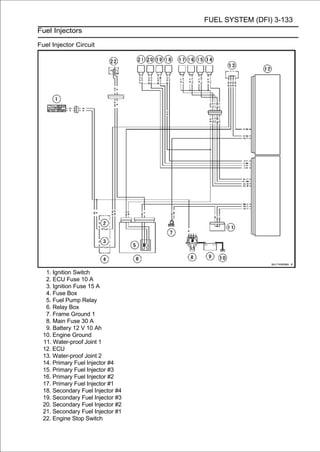
![FUEL SYSTEM (DFI) 3-135
Throttle Body Assy
Idle Speed Inspection/Adjustment
• Refer to the Idle Speed Inspection/Adjustment in the
Periodic Maintenance chapter.
Synchronization Inspection/Adjustment
• Refer to the Engine Vacuum Synchronization Inspection in
the Periodic Maintenance chapter.
Throttle Body Assy Removal
WARNING
Gasoline is extremely flammable and can be explo-
sive under certain conditions. Make sure the area
is well-ventilated and free from any source of flame
or sparks; this includes any appliance with a pilot
light. Do not smoke. Turn the ignition switch OFF.
Be prepared for fuel spillage: any spilled fuel must
be completely wiped up immediately.
CAUTION
Never drop the throttle body assy, especially on a
hard surface. Such a shock to the body assy can
damage it.
• Remove:
Air Cleaner Housing (see Air Cleaner Housing Removal)
Primary and Secondary Fuel Hoses (see Fuel Hose
Replacement in the Periodic Maintenance chapter)
Upper Fairing Covers (see Upper Fairing Cover
Removal in the Frame chapter)
Coolant Reserve Tank (see Coolant Reserve Tank Re-
moval in the Cooling System chapter)
• [A] of theto place body assy.cloth around the delivery pipe
Be sure
throttle
a piece of
• Disconnect the engine subharness #2 connector [B].
• Disconnect the camshaft position sensor lead connector
[A].
• For the California and Southeast Asia models, pull off the
vacuum hoses [B].](https://image.slidesharecdn.com/2008-100321201635-phpapp01/85/2008-228-320.jpg)
![3-136 FUEL SYSTEM (DFI)
Throttle Body Assy
• Loosen the throttle body assy holder clamp bolts [A] on
both sides.
• Remove:
Throttle Case
Throttle Cable Upper Ends [A]
• Remove the adjusting screw [A] from the clamp [B].
• Remove the throttle body assy [A] from the throttle body
assy holders.
• After removing the throttle body assy, stuff pieces of lint
-free, clean cloth into the throttle body assy holders.
CAUTION
If dirt gets into the engine, excessive engine wear
and possible engine damage will occur.
• Remove:
Clamp [B]
Throttle Cable Lower Ends [C]](https://image.slidesharecdn.com/2008-100321201635-phpapp01/85/2008-229-320.jpg)
![FUEL SYSTEM (DFI) 3-137
Throttle Body Assy
Throttle Body Assy Installation
• Apply a thin coat of grease to the throttle cable lower ends.
• Fit the accelerator cable end [A] and the decelerator cable
end [B] into the throttle pulley.
○The accelerator cable has a clamp [C].
• Install the clamp securely.
• Install the throttle body assy holder clamp bolts as shown in
the figure.
Bolt Heads [A]
Front [B]
• Tighten:
Torque - Throttle Body Assy Holder Clamp Bolts: 2.0 N·m
(0.20 kgf·m, 18 in·lb)
• Apply a thin coat of grease to the throttle cable upper
ends.
• Install the upper ends of the throttle cables in the grip.
• Fit the projection [A] of the throttle case into the hole [B] of
the handlebar.
• Turnsmoothly andgrip andbymake sure that the throttle pulley
moves
the throttle
return spring force.
• RunRouting section in the Appendix chapter). Wire, and
Hose
the leads and hoses correctly (see Cable,
• Adjust:
Throttle Grip Free Play (see Throttle Control System In-
spection in the Periodic Maintenance chapter)
Idle Speed (see Idle Speed Adjustment in the Periodic
Maintenance chapter)](https://image.slidesharecdn.com/2008-100321201635-phpapp01/85/2008-230-320.jpg)
![3-138 FUEL SYSTEM (DFI)
Throttle Body Assy
Throttle Body Assy Disassembly
1. Subthrottle Valve Actuator
2. Subthrottle Sensor
3. Main Throttle Sensor
4. Throttle Body Assy
5. Primary Fuel Injectors
6. Delivery Pipe Assy
7. Engine Subharness #2
CAUTION
Do not remove, disassemble or adjust the main
throttle sensor, subthrottle sensor, subthrottle
valve actuator, throttle link mechanism and throttle
body assy, because they are adjust or set surely at
the manufacturer. Adjustment of these parts could
result in poor performance, requiring replacement
of the throttle body assy.
• Remove the throttle body assy (see Throttle Body Assy
Removal).
• Cut the band [A], and disconnect the subthrottle valve
actuator connector [B].](https://image.slidesharecdn.com/2008-100321201635-phpapp01/85/2008-231-320.jpg)
![FUEL SYSTEM (DFI) 3-139
Throttle Body Assy
• Disconnect:
Inlet Air Pressure Sensor Connector [A]
Main Throttle Sensor Connector [B]
Subthrottle Sensor Connector [C]
• Disconnect the primary fuel injector connectors [A].
• Remove the screws [A] to assy out the primary fuel injec-
tors [B] from the throttle body
pull
together with the de-
livery pipe assy [C].
NOTE
○Do not damage the insertion portions of the injectors
when they are pulled out from the throttle body.
• Pull out the primary fuel injectors from the delivery pipe
assy.
NOTE
○Do not damage the insertion portions of the injectors
when they are pulled out from the delivery pipe assy.
CAUTION
Never drop the primary fuel injector, especially on
a hard surface. Such a shock to the injector can
damage it.
Throttle Body Assy Assembly
• Before assembling, blow away dirt or dust from the throttle
body and delivery pipe assy by applying compressed air.
• Replace the O-rings [A] of each primary fuel injector [B]
with new ones.
• Apply engine oil to the new O-rings, insert them to the
delivery pipe assy [C] and confirm whether the injectors
turn smoothly or not.](https://image.slidesharecdn.com/2008-100321201635-phpapp01/85/2008-232-320.jpg)
![3-140 FUEL SYSTEM (DFI)
Throttle Body Assy
• Replace the dust seals [A] with new ones.
• Apply engine oil to the new dust seals.
• Install thethe throttlefuel injectors along with the delivery
pipe assy to
primary
body.
• Tighten:
Torque - Delivery Pipe Assy Mounting Screws (Throttle
Body Assy): 3.4 N·m (0.35 kgf·m, 30 in·lb)
• Connect the subthrottle valve actuator connector, and
bind the harness with band.
• Install the throttle body assy (see Throttle Body Assy
Installation).](https://image.slidesharecdn.com/2008-100321201635-phpapp01/85/2008-233-320.jpg)
![FUEL SYSTEM (DFI) 3-141
Nozzle Assy
Nozzle Assy Removal
• Remove the fuel tank (see Fuel Tank Removal).
• Disconnect the secondary fuel hose [A] from the delivery
pipe of the nozzle assy [B] (see Fuel Hose Replacement
in the Periodic Maintenance chapter).
• Disconnect the secondary fuel injector connectors [C].
• Remove:
Nozzle Assy Mounting Bolts [D]
Nozzle Assy
Nozzle Assy Installation
•Tighten:
Torque - Nozzle Assy Mounting Bolts: 7.0 N·m (0.71 kgf·m,
62 in·lb)
• Run thethe Appendix chapter). Wire, and Hose Routing
section in
leads correctly (see Cable,
• Connectassy secondaryHosehose to the delivery Pe- of
the nozzle
the
(see Fuel
fuel
Replacement in the
pipe
riodic Maintenance chapter).
Nozzle Assy Disassembly
• Remove the nozzle assy (see Nozzle Assy Removal).
• Remove the screws [A] to pull out the secondary fuel in-
jectors [B] from the stay plate [C] together with the delivery
pipe assy [D].
NOTE
○Do not damage the insertion portions of the injectors
when they are pulled out from the stay plate.
• Pull out the secondary fuel injectors from the delivery pipe
assy.
NOTE
○Do not damage the insertion portions of the injectors
when they are pulled out from the delivery pipe assy.
CAUTION
Never drop the secondary fuel injector, especially
on a hard surface. Such a shock to the injector can
damage it.
• Separate the delivery pipe assy.
NOTE
○Mark and record the location of the delivery pipes and
the joint pipe so that the delivery pipe assy can be
reassembled in the original position.](https://image.slidesharecdn.com/2008-100321201635-phpapp01/85/2008-234-320.jpg)
![3-142 FUEL SYSTEM (DFI)
Nozzle Assy
Nozzle Assy Assembly
• Before assembling, blow away dirt or dust from the delivery
pipes [A] by applying compressed air [B].
• Replace the O-rings [A] of the joint pipe [B] with new ones.
• Apply pipes [C]. to the new O-rings, and insert it to the
delivery
engine oil
○Insert the joint pipe so that the stepped side [D] faces left
side.
○Left and right delivery pipes are identical.
• Replace the O-rings [A] of each secondary fuel injector
[B] with new ones.
• Apply pipe assy [C] and new O-rings, and insert them to the
delivery
engine oil to the
confirm whether the injectors
turn smoothly or not.
• Replace the dust seals [A] with new ones.
• Apply engine oil to the new dust seals.
• Install thethe stay platefuel injectors along with the delivery
pipe assy to
secondary
[B].
• Tighten:
Torque - Delivery Pipe Assy Mounting Screws (Nozzle
Assy): 3.4 N·m (0.35 kgf·m, 30 in·lb)
• Install the nozzle assy (see Nozzle Assy Installation).](https://image.slidesharecdn.com/2008-100321201635-phpapp01/85/2008-235-320.jpg)
![FUEL SYSTEM (DFI) 3-143
Air Cleaner
Air Cleaner Element Removal/Installation
• Refer to the Air Cleaner Element Replacement in the
Periodic Maintenance chapter.
Air Cleaner Element Inspection
• Remove the air cleaner element (see Air Cleaner Element
Replacement in the Periodic Maintenance chapter).
• Visually check the element [A] for tears or breaks.
If the element has any tears or breaks, replace the ele-
ment.
Air Cleaner Oil Draining
A drain hose is connected to the bottom of the air cleaner to
drain water or oil accumulated in the cleaner part.
• Remove the left lower fairing (see Lower Fairing Removal in
the Frame chapter).
• Visually check the drain hose [A] if the water or oil
accumulates.
If any water or oil accumulates in the hose, remove the
plug [B] from the drain hose and drain it.
WARNING
Be sure to reinstall the plug in the drain hose after
draining. Oil on tires will make them slippery and
can cause an accident and injury.
Air Cleaner Housing Removal
• Remove the fuel tank (see Fuel Tank Removal).
• Disconnect the secondary fuel hose [A] from the delivery
pipe of the nozzle assy [B] (see Fuel Hose Replacement
in the Periodic Maintenance chapter).
• Open the clamp [C].
• Disconnect:
Inlet Air Temperature Sensor Connector [D]
Secondary Fuel Injector Connectors [E]
• For the rubber plate [A].
remove the
United States, Canada and California models,](https://image.slidesharecdn.com/2008-100321201635-phpapp01/85/2008-236-320.jpg)
![3-144 FUEL SYSTEM (DFI)
Air Cleaner
• Remove:
Air Cleaner Housing Assembly Screws [A]
Clamp [B]
Upper Air Cleaner Housing [C]
• Remove:
Air Cleaner Housing Mounting Bolt (Upper) [A]
Middle Air Cleaner Housing [B] (with Element [C])
• Separate the air switching valve hose [A] from the lower air
cleaner housing.
• Remove:
Air Cleaner Drain Hose [A]
Breather Hose [B]
• Remove:
Air Cleaner Housing Mounting Bolts (Lower) [A]
Air Ducts [B]](https://image.slidesharecdn.com/2008-100321201635-phpapp01/85/2008-237-320.jpg)
![FUEL SYSTEM (DFI) 3-145
Air Cleaner
• Turn the lower air cleaner housing [A] clockwise [B], and
remove it upward.
Air Cleaner Housing Installation
• Replace the O-rings [A] with new ones.
• Apply grease to the new O-rings, and fit them into the
grooves of the throttle body assy [B] securely.
• Replace the O-rings [A] with new ones.
• Apply as shown in the figure. and install them on each air
duct [B]
grease to the new O-rings,
• Install the air ducts [A] as shown in the figure.
Front [B]
○The air duct #2 and #3 are identical.
• Apply a non-permanent locking (lower),toand tighten of the
air cleaner housing mounting bolts
agent the treads
them.
Torque - Air Cleaner Housing Mounting Bolts (Lower): 4.2
N·m (0.43 kgf·m, 37 in·lb)
• Run thethe Appendix chapter).Cable, Wire, and Hose Routing
section in
hoses correctly (see
• Tighten:
Torque - Air Cleaner Housing Mounting Bolt (Upper): 7.0
N·m (0.71 kgf·m, 62 in·lb)](https://image.slidesharecdn.com/2008-100321201635-phpapp01/85/2008-238-320.jpg)
![3-146 FUEL SYSTEM (DFI)
Air Cleaner
• Install the clamp [A] as shown in the figure.
• Tighten:
Torque - Air Cleaner Housing Assembly Screws: 1.1 N·m
(0.11 kgf·m, 9.7 in·lb)
• Run thethe Appendix chapter). Wire, and Hose Routing
section in
leads correctly (see Cable,
○Fit the harness (for secondary fuel injectors and inlet air
temperature sensor) [B] into the groove [C] of the lower air
cleaner housing and fix it with the clamp.
• Connect the secondary fuel hose to the delivery pipe of
the nozzle assy (see Fuel Hose Replacement in the Pe-
riodic Maintenance chapter).
• For United States, Canada and California models, install
the rubber plate [A] as follows.
○Install the rubber plate so that the pads [B] faces upward.
○Insert the projection [C] of the holder [D] into the slit [E] of the
rubber plate.
○Install the rubber plate so that the secondary fuel hose [F] fits
into groove [G].](https://image.slidesharecdn.com/2008-100321201635-phpapp01/85/2008-239-320.jpg)
![FUEL SYSTEM (DFI) 3-147
Air Cleaner
○Cover the secondary fuel hose [A] with the rear end [B] of the
rubber plate as shown in the figure.
Left Side View [C]
○Set the rear end of the rubber plate faces downward.](https://image.slidesharecdn.com/2008-100321201635-phpapp01/85/2008-240-320.jpg)
![3-148 FUEL SYSTEM (DFI)
Air Line
Air Inlet Duct Removal
• Remove:
Upper Fairing Assembly (see Upper Fairing Assembly
Removal in the Frame chapter)
Air Inlet Duct Mounting Bolts [A] (Both Sides)
Air Inlet Duct [B] (with Resonator Tank [C])
Air Inlet Duct Installation
• Check that the pads [A] are in place on the air inlet duct.
• Apply a non-permanent locking agent to the treads of the air
inlet duct mounting bolts, and tighten them.
Torque - Air Inlet Duct Mounting Bolts: 7.0 N·m (0.71 kgf·m,
62 in·lb)
• Run thethe Appendix chapter). Wire, and Hose Routing
section in
lead correctly (see Cable,](https://image.slidesharecdn.com/2008-100321201635-phpapp01/85/2008-241-320.jpg)
![FUEL SYSTEM (DFI) 3-149
Fuel Tank
Fuel Tank Removal
WARNING
Gasoline is extremely flammable and can be explo-
sive under certain conditions. Make sure the area
is well-ventilated and free from any source of flame
or sparks; this includes any appliance with a pilot
light. Do not smoke. Turn the ignition switch OFF
and disconnect the battery (-) terminal.
To avoid fire, do not remove the fuel tank when the
engine is still hot. Wait until it cools down.
To make fuel spillage minimum, draw the fuel out
from the fuel tank when the engine is cold.
Be prepared for fuel spillage; any spilled fuel must
be completely wiped up immediately.
• Turn the ignition switch OFF.
• Remove the front seat (see Front Seat Removal in the
Frame chapter).
• Wait until the engine cools down.
• DisconnectSystem chapter).
the Electrical
the battery (-) terminal (see Battery Removal in
• Remove the fuel tank bolts [A].
• Open the fuel tank cap [A] to lower the pressure in the
tank.
○During tank removal, keep the tank cap open to release
pressure in the tank. This makes fuel spillage less.
• Draw the fuel[A]. from the fuel tank with a commercially
available pump
out
○Use a soft plastic hose [B] as a pump inlet hose in order to
insert the hose smoothly.
○Put the hose through the fill opening [C] into the tank and
draw the fuel out.
Front [D]
WARNING
The fuel could not be removed completely from the
fuel tank. Be careful for remained fuel spillage.](https://image.slidesharecdn.com/2008-100321201635-phpapp01/85/2008-242-320.jpg)
![3-150 FUEL SYSTEM (DFI)
Fuel Tank
• Disconnect the fuel pump lead connector [A].
• Remove:
Fuel Tank Drain Hose [B]
Fuel Tank Bolt [C]
• For the California and Southeast Asia models, remove the
following.
Fuel Return Hose [A] (left side, red)
Fuel Tank Breather Hose [B] (right side, blue)
• Be sure to place a piece of cloth [A] around the fuel hose
joint.
• Insert a[D]. blade screwdriver [B] into the slit [C] on the
joint lock
thin
• Turn [A] the driver to disconnect the joint lock [B].
• Pull the fuel hose joint [C] out of the outlet pipe.
WARNING
Be prepared for fuel spillage; any spilled fuel must be
completely wiped up immediately.
When the fuel hose is disconnected, fuel spills out
from the hose and the pipe. Cover the hose connec-
tion with a clean shop towel to prevent fuel spillage.
• Close the fuel tank cap.
• Remove the fuel tank, and place a it on a flat surface.
○Do not apply the load to the fuel outlet pipe of the fuel
pump.](https://image.slidesharecdn.com/2008-100321201635-phpapp01/85/2008-243-320.jpg)
![FUEL SYSTEM (DFI) 3-151
Fuel Tank
• For the California and Southeast Asia models, note the
following.
CAUTION
For the California and Southeast Asia models, if
gasoline, solvent, water or any other liquid enters
the canister, the canister’s vapor absorbing capac-
ity is greatly reduced. If the canister does become
contaminated, replace it with a new one.
○Be sure to plug the evaporative fuel return hose to prevent
fuel spilling before fuel tank removal.
WARNING
For the California and Southeast Asia models, be
careful not to spill the gasoline through the return
hose. Spilled fuel is hazardous.
If liquid or gasoline flows into the breather hose, remove the
hose and blow it clean with compressed air.
○Be careful of fuel spillage from the fuel tank since fuel still
remains in the fuel tank and fuel pump.
WARNING
Store the fuel tank in an area which is well
-ventilated and free from any source of flame or
sparks. Do not smoke in this area. Place the fuel
tank on a flat surface and plug the fuel pipes to
prevent fuel leakage.
Fuel Tank Installation
• Note the above WARNING (see Fuel Tank Removal).
• Run the hoses correctly (see Cable, Wire, and Hose Routing
section in the Appendix chapter).
• Check that the dampers [A] and pads [B] are in place on
the frame and the fuel tank.
If the dampers are damaged or deteriorated, replace
them.](https://image.slidesharecdn.com/2008-100321201635-phpapp01/85/2008-244-320.jpg)
![3-152 FUEL SYSTEM (DFI)
Fuel Tank
• For the California and Southeast Asia models, note the
following.
○To prevent the gasoline from flowing into or out of the
canister, hold the separator perpendicular to the ground.
○Connect the hoses according to the diagram of the evap-
orative emission control system. Make sure they do not
get pinched or kinked.
○Run the hoses with a minimum of bending so that the air or
vapor will not be obstructed.
• Insert [A] the fuel hose joint [B] straight onto the fuel outlet
pipe until the hose joint clicks.
• Push [C] the joint lock [D] until the hose joint clicks.
• Push and pull [A] and makehose itjointlocked and and forth
more than two times,
the fuel
sure is
[B] back
does
not come off.
WARNING
Make sure the hose joint is installed correctly on the
delivery pipe or the fuel could leak.
If it comes off, reinstall the hose joint.
• Connect the fuel pump lead connector and the battery (-)
terminal (see Battery Installation in the Electrical System
chapter).
Fuel Tank Inspection
• Visually inspect the gasket [A] on the tank cap for any
damage.
Replace the gasket if it is damaged.
• Check to see if the water drain pipe [B] and fuel breather
pipe [C] (California and Southeast Asia models) in the
tank are not clogged. Check the tank cap breather also. If
they are clogged, remove the tank and drain it, and then blow
the breather free with compressed air.
CAUTION
Do not apply compressed air to the air vent holes
[D] in the tank cap. This could cause damage and
clogging of the labyrinth in the cap.](https://image.slidesharecdn.com/2008-100321201635-phpapp01/85/2008-245-320.jpg)
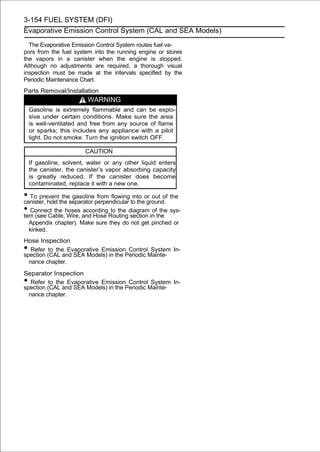
![FUEL SYSTEM (DFI) 3-155
Evaporative Emission Control System (CAL and SEA Models)
Separator Operation Test
WARNING
Gasoline is extremely flammable and can be ex-
plosive under certain conditions. Do not smoke.
Turn the ignition switch OFF. Make sure the area is
well-ventilated and free from any source of flame
or sparks; this includes any appliance with a pilot
light.
• Connect the motorcycle. the separator, and install the
separator on
the hoses to
• DisconnectmL (0.68 US oz.) of from the [A] into the and in-
ject about 20
the breather hose
gasoline
separator,
separator [B] through the hose fitting.
• Disconnect the fuel return hose [C] from the fuel tank [D].
• Run the level with the tank return hose into the container
and hold it
open end of the
top [E].
• Start the engine, and let it idle.
If the gasoline in the separator comes out of the hose, the
separator works well. If it does not, replace the separator
with a new one.
Canister Inspection
• Refer to the Evaporative Emission Control System In-
spection (CAL and SEA Models) in the Periodic Mainte-
nance chapter.](https://image.slidesharecdn.com/2008-100321201635-phpapp01/85/2008-248-320.jpg)
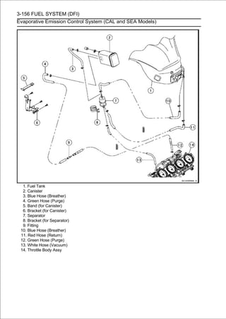
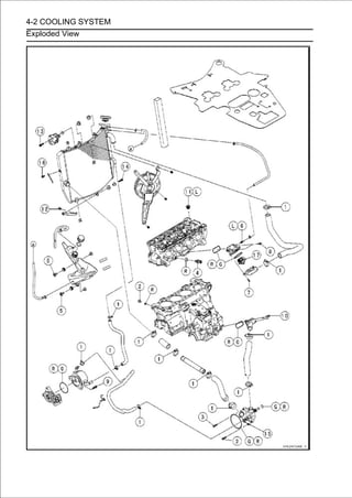
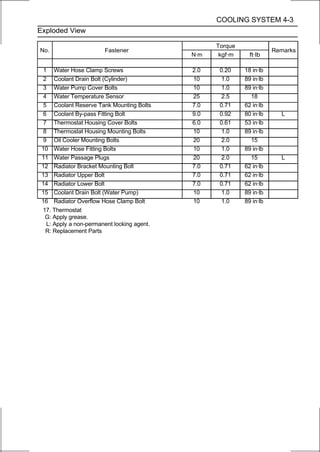
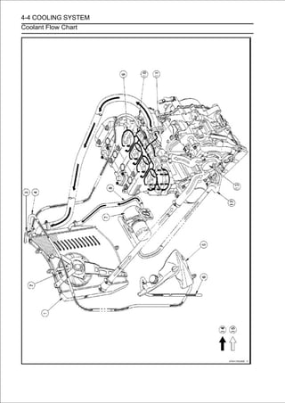
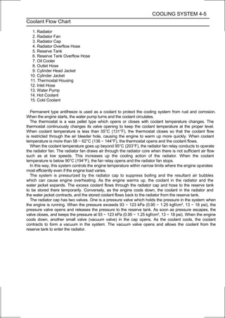
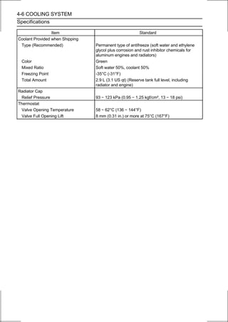
![COOLING SYSTEM 4-7
Coolant
Coolant Deterioration Inspection
• Remove the left upper fairing cover (see Upper Fairing
Cover Removal in the Frame chapter).
•Visually inspect the coolant in the reserve tank [A].
If whitish cotton-like wafts are observed, aluminum parts
in the cooling system are corroded. If the coolant is
brown, iron or steel parts are rusting. In either case, flush
the cooling system.
If the coolant gives off an abnormal smell, check for a
cooling system leak. It may be caused by exhaust gas
leaking into the cooling system.
Coolant Level Inspection
• Refer to the Coolant Level Inspection in the Periodic
Maintenance chapter.
Coolant Draining
• Refer to the Coolant Change in the Periodic Maintenance
chapter.
Coolant Filling
• Refer to the Coolant Change in the Periodic Maintenance
chapter.
Pressure Testing
• Remove:
Right Upper Inner Fairing (see Upper Inner Fairing Re-
moval in the Frame chapter)
Radiator Cap [A]
○Remove the radiator cap in two steps. First turn the cap
counterclockwise to the first stop. Then push and turn it
further in the same direction and remove the cap.
• Install the cooling system pressure tester [A] on the filler
neck.
NOTE
○Wet the cap sealing surfaces with water or coolant to
prevent pressure leaks.
• Build reaches 123 kPa (1.25 kgf/cm², 18 psi).
pressure
up pressure in the system carefully until the
CAUTION
During pressure testing, do not exceed the pres-
sure for which the system is designed. The maxi-
mum pressure is 123 kPa (1.25 kgf/cm², 18 psi).
• Watch the gauge for at least 6 seconds.
If the pressure holds steady, the system is all right.
If the pressure drops and no external source is found,
check for internal leaks. Droplets in the engine oil indicate
internal leakage. Check the cylinder head gasket and the
water pump.
• Remove the pressure tester, replenish the coolant, and
install the radiator cap.](https://image.slidesharecdn.com/2008-100321201635-phpapp01/85/2008-256-320.jpg)
![4-8 COOLING SYSTEM
Coolant
Cooling System Flushing
Over a period of time, the cooling system accumulates
rust, scale, and lime in the water jacket and radiator. When
this accumulation is suspected or observed, flush the cooling
system. If this accumulation is not removed, it will clog up the
water passage and considerable reduce the efficiency of
the cooling system.
• Drain the cooling system (see Coolant Change in the
Periodic Maintenance chapter).
• Fill the cooling system with fresh water mixed with a flushing
compound.
CAUTION
Do not use a flushing compound which is harmful to
the aluminum engine and radiator. Carefully follow
the instructions supplied by the manufacturer of the
cleaning product.
• Warm upfor about ten minutes. it at normal operating
temperature
the engine, and run
• Stop the engine, and drain the cooling system.
• Fill the system with fresh water.
• Warm up the engine and drain the system.
• Repeat the previous two steps once more.
• Fill the system with a(see Coolant type coolant and bleed
the air from the system
permanent
Change in the Peri-
odic Maintenance chapter).
Coolant Reserve Tank Removal
•Remove:
Left Upper Fairing Cover (see Upper Fairing Cover Re-
moval in the Frame chapter)
Coolant Reserve Tank Mounting Bolts [A]
•Remove the cap [B] and poor the coolant into a container.
•Remove:
Radiator Overflow Hose [C]
Reserve Tank Overflow Hose [D]
Coolant Reserve Tank [E]](https://image.slidesharecdn.com/2008-100321201635-phpapp01/85/2008-257-320.jpg)
![COOLING SYSTEM 4-9
Coolant
Coolant Reserve Tank Installation
• Be sure that the pads [A] are in positions on the coolant
reserve tank [B].
• Install the following to the coolant reserve tank.
Rubber Dampers [C]
Collars [D]
Gasket [E]
Cap [F]
• Tighten:
Torque - Coolant Reserve Tank Mounting Bolts [G]: 7.0 N·m
(0.71 kgf·m, 62 in·lb)
• Run thethe Appendix chapter.Cable, Wire, and Hose Routing
section in
hoses according to
• Fill the the Periodic Maintenance chapter). (see Coolant
Change in
coolant reserve tank with coolant](https://image.slidesharecdn.com/2008-100321201635-phpapp01/85/2008-258-320.jpg)
![4-10 COOLING SYSTEM
Water Pump
Water Pump Removal
•Drain:
Coolant (see Coolant Change in the Periodic Mainte-
nance chapter)
Engine Oil (see Engine Oil Change in the Periodic
Maintenance chapter)
•Remove:
Engine Sprocket Cover (see Engine Sprocket Removal
in the Final Drive chapter)
Water Hoses [A]
• Remove:
Water Pump Cover Bolts [A]
Water Pump Cover [B]
• Remove the water hose [A].
• Remove the water pump body [B] with impeller [C].
Water Pump Installation
•Replace the O-ring [A] with a new one.
•Apply grease to the new O-ring.
• Run the gear position switch lead [A] as shown in the
figure.](https://image.slidesharecdn.com/2008-100321201635-phpapp01/85/2008-259-320.jpg)
![COOLING SYSTEM 4-11
Water Pump
• Turn the impeller[B] of the oil pump gear shaft. its shaft fits
onto the projection
shaft so that the slot [A] in
CAUTION
Do not pinch the gear position switch lead.
• Install the water hose [A] so that the white mark [B] faces
outside.
• Install the hose clamp [C] as shown in the figure.
• Tighten:
Torque - Water Hose Clamp Screw: 2.0 N·m (0.20 kgf·m, 18
in·lb)
• Replace the O-ring [D] with a new one.
• Apply grease to the new O-ring.
• Tighten:
Torque - Water Pump Cover Bolts: 10 N·m (1.0 kgf·m, 89
in·lb)
• Install the water hose [A] as follows.
○Install the water hose so that the white mark [B] faces
backward.
○Run the water hose over the water pump cover bolt [C] as
shown in the figure.
Limit of Upper Side [D]
Limit of Lower Side [E]
• Install the hose clamp [F] as shown in the figure.
• Tighten:
Torque - Water Hose Clamp Screw: 2.0 N·m (0.20 kgf·m, 18
in·lb)](https://image.slidesharecdn.com/2008-100321201635-phpapp01/85/2008-260-320.jpg)
![4-12 COOLING SYSTEM
Water Pump
• Align thethe waterof the [C]. pump cover and the white
mark [B] of
line [A]
hose
water
• Install the hose clamp [D] as shown in the figure.
• Tighten:
Torque - Water Hose Clamp Screw: 2.0 N·m (0.20 kgf·m, 18
in·lb)
Water Pump Impeller Inspection
• Remove the water pump cover (see Water Pump Re-
moval).
•Visually inspect the water pump impeller [A].
If the surface is corroded or if the blades are damaged,
replace the water pump assy.](https://image.slidesharecdn.com/2008-100321201635-phpapp01/85/2008-261-320.jpg)
![COOLING SYSTEM 4-13
Radiator
Radiator and Radiator Fan Removal
• Drain the coolant (see Coolant Change in the Periodic
Maintenance chapter).
• Remove the upper fairing assembly (see Upper Fairing
Assembly Removal in the Frame chapter).
• Open the clamp [A].
• For the California and Southeast Asia models, remove the
following.
Separator Bracket Mounting Bolt [B]
Clamp
Separator [C]
• Remove: Hose [D]
Radiator
Radiator upper Bolt [E]
Horn [F]
• Remove: Cap [A]
Radiator
Radiator Hoses [B]
Radiator Lower Bolt [C]
• Pull the radiator from the projection [D], and lower the
radiator.
CAUTION
Do not touch the radiator core. This could damage
the radiator fins, resulting in loss of cooling effi-
ciency.
• Slide the dust cover [A].
• Disconnect the radiator fan lead connector [B] and re-
move the radiator.
○Remove the bolt [A] and radiator bracket [B] as necessary.](https://image.slidesharecdn.com/2008-100321201635-phpapp01/85/2008-262-320.jpg)
![4-14 COOLING SYSTEM
Radiator
• Remove:
Radiator Fan Mounting Bolts [A]
Radiator Fan [B]
Radiator and Radiator Fan Installation
•Check that the pad [A] is in place on the radiator.
• Install the radiator fan [A].
• Install the rubber dampers [B] and collars [C] as shown in the
figure.](https://image.slidesharecdn.com/2008-100321201635-phpapp01/85/2008-263-320.jpg)
![COOLING SYSTEM 4-15
Radiator
• Remove the radiator cap [A] temporarily.
• Cover the the figure. rubber plate [B] on the radiator [C]
as shown in
heat insulation
• Reinstall the radiator cap.
• Run therubber plate. lead [D] to the hole [E] of the heat
insulation
radiator fan
• Connect radiator fan lead connector.
• Run therubber plate, then run it over thehole [F] plate. heat
insulation
radiator overflow hose to the
rubber
of the
• Install the radiator [A] in the projection [B] as shown in the
figure.](https://image.slidesharecdn.com/2008-100321201635-phpapp01/85/2008-264-320.jpg)
![4-16 COOLING SYSTEM
Radiator
If the radiator bracket [A] was removed, install it.
Torque - Radiator Bracket Mounting Bolt [B]: 7.0 N·m (0.71
kgf·m, 62 in·lb)
• Install the horn [C].
• Tighten:
Torque - Radiator Upper Bolt [D]: 7.0 N·m (0.71 kgf·m, 62
in·lb)
Radiator Lower Bolt [E]: 7.0 N·m (0.71 kgf·m, 62
in·lb)
• Facein the figure. [F] of the radiator hose [G] direction as
shown
the white mark
• Install the water hose clamp [H].
Torque - Water Hose Clamp Screw: 2.0 N·m (0.20 kgf·m, 18
in·lb)
• Run platecoolant return hose [I] under the heat insulation
rubber
the
and install it.
• Run plateradiator overflow hose [J] over the heat insulation
rubber
the
and install it.
• For the[K] and clamp [L].
separator
California and Southeast Asia models, install the
Torque - Separator Bracket Mounting Bolt [M]: 7.0 N·m
(0.71 kgf·m, 62 in·lb)
○Run the canister and separator hoses according to Cable,
Wire, and Hose Routing section in the Appendix chapter.
• Fix the radiator overflow hose to the radiator with clamp
[L].
• Fill the radiator with coolant (see Coolant Change in the
Periodic Maintenance chapter).](https://image.slidesharecdn.com/2008-100321201635-phpapp01/85/2008-265-320.jpg)
![COOLING SYSTEM 4-17
Radiator
Radiator Inspection
• Remove the radiator (see Radiator and Radiator Fan Re-
moval).
•Check the radiator core.
If there are obstructions to air flow, remove them.
If the corrugated fins [A] are deformed, carefully
straighten them.
If the air passages of the radiator core are blocked more
than 20% by unremovable obstructions or irreparably
deformed fins, replace the radiator with a new one.
CAUTION
When cleaning the radiator with steam cleaner, be
careful of the following to prevent radiator damage:
Keep the steam gun [A] away more than 0.5 m (1.6 ft)
[B] from the radiator core.
Hold the steam gun perpendicular [C] (not oblique
[D]) to the core surface.
Run the steam gun, following the core fin direction.](https://image.slidesharecdn.com/2008-100321201635-phpapp01/85/2008-266-320.jpg)
![4-18 COOLING SYSTEM
Radiator
Radiator Cap Inspection
• Remove the radiator cap (see Pressure Testing).
• Check the condition of the bottom [A] and top [B] valve
seals and valve spring [C].
If any one of them shows visible damage, replace the cap
with a new one.
• Install the cap [A] on a cooling system pressure tester [B].
NOTE
○Wet the cap sealing surfaces with water or coolant to
prevent pressure leaks.
• Watchingthe pressure until the relief valve opens: thetester
to build up
the pressure gauge, pump the pressure
gauge needle flicks downward. Stop pumping and mea-
sure leak time at once. The relief valve must open within
the specified range in the table below and the gauge hand
must remain within the same range at least 6 seconds.
Radiator Cap Relief Pressure
Standard: 93 ∼ 123 kPa (0.95 ∼ 1.25 kgf/cm², 13 ∼ 18
psi)
If the cap can not hold the specified pressure or if it holds too
much pressure, replace it with a new one.
Radiator Filler Neck Inspection
• Remove the radiator cap (see Pressure Testing).
• Check the radiator filler neck for signs of damage.
• Check the condition of the top and bottom sealing seats
[A] in the filler neck. They must be smooth and clean for
the radiator cap to function properly.](https://image.slidesharecdn.com/2008-100321201635-phpapp01/85/2008-267-320.jpg)
![COOLING SYSTEM 4-19
Thermostat
Thermostat Removal
• Drain the coolant (see Coolant Change in the Periodic
Maintenance chapter).
•Remove:
Throttle Body Assy (see Throttle Body Assy Removal in
the Fuel System (DFI) chapter)
Water Hoses [A]
Thermostat Housing Mounting Bolts [B]
• Remove:
Thermostat Housing Cover Bolts [A]
Thermostat Housing Cover [B]
Thermostat
○Remove the coolant by-pass fitting bolt [C] as necessary.
Thermostat Installation
• Install the thermostat [A] in the housing so that the air
bleeder hole [B] is on top.
• Replace the O-rings [A] with new ones.
• Apply grease to the new O-rings.
• Install a new O-rings into the thermostat housing [B] and
cover [C].
If the coolant by-pass fitting bolt [D] was removed, install it
as follows.
○Apply a non-permanent locking agent to the threads of
the coolant by-pass fitting bolt, and tighten it.
Torque - Coolant By-pass Fitting Bolt: 9.0 N·m (0.92 kgf·m,
80 in·lb)
• Tighten the thermostat housing cover bolts [E].
Torque - Thermostat Housing Cover Bolts: 6.0 N·m (0.61
kgf·m, 53 in·lb)](https://image.slidesharecdn.com/2008-100321201635-phpapp01/85/2008-268-320.jpg)
![4-20 COOLING SYSTEM
Thermostat
• Install the thermostat housing.
• Tighten:
Torque - Thermostat Housing Mounting Bolts: 10 N·m (1.0
kgf·m, 89 in·lb)
• Run the water hose in the Engine Removal/Installa- plate
(see Engine Installation
under the heat insulation rubber
tion chapter).
• Align the thermostat housing cover bolt [A] and the white
mark [B] of the water hose [C].
• Install the water hose clamp [D].
• Tighten:
Torque - Water Hose Clamp Screw: 2.0 N·m (0.20 kgf·m, 18
in·lb)
• Install the removed parts (see appropriate chapters).
• Fill theMaintenance chapter). (see Coolant Change in the
Periodic
radiator with coolant
Thermostat Inspection
•Remove the thermostat (see Thermostat Removal).
•Inspect the thermostat valve [A] at room temperature.
If the valve is open, replace the thermostat with a new
one.
• To check a container of water and raisesuspend the ther-
mostat [A] in
valve opening temperature,
the tempera-
ture of the water.
○The thermostat must be completely submerged and must
not touch the container sides or bottom. Suspend an ac-
curate thermometer [B] in the water so that the heat sen-
sitive portions [C] are located in almost the same depth. It
must not touch the container, either.
If the measurement is out of the specified range, replace
the thermostat with a new one.
Thermostat Valve Opening Temperature
58 ∼ 62°C (136 ∼ 144°F)](https://image.slidesharecdn.com/2008-100321201635-phpapp01/85/2008-269-320.jpg)
![COOLING SYSTEM 4-21
Hoses and Pipes
Hose Installation
• Install the hoses and pipes, being careful to follow bend-
ing direction. Avoid sharp bending, kinking, flattening or
twisting.
• Run the hoses in accordance with the Cable, Wire, and
Hose Routing section in the Appendix chapter.
• Install the clamp [A] as near as possible to the hose end
to clear the raised rib of the fitting. This will prevent the
hoses from working loose.
○The clamp screws should be positioned correctly to pre-
vent the clamps from contacting the other parts.
○Tighten:
Torque - Water Hose Clamp Screws: 2.0 N·m (0.20 kgf·m,
18 in·lb)
Hose Inspection
• Refer to the Radiator Hose and Pipe Inspection in the
Periodic Maintenance chapter.](https://image.slidesharecdn.com/2008-100321201635-phpapp01/85/2008-270-320.jpg)
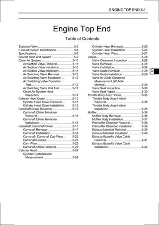
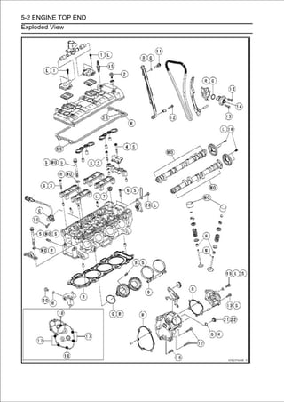
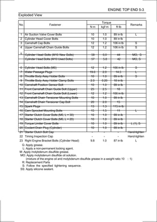
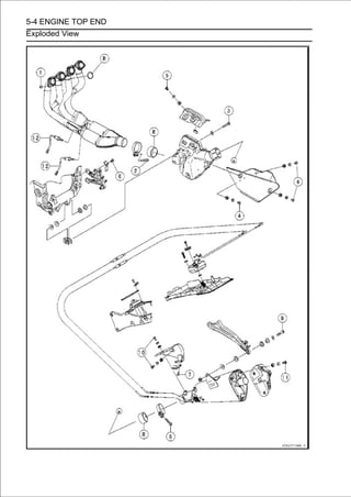
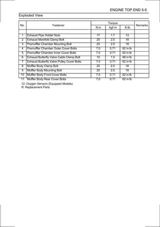
![5-6 ENGINE TOP END
Exhaust System Identification
Exhaust Manifold Mark Position [A]
Premuffler Chamber Mark Position [A]](https://image.slidesharecdn.com/2008-100321201635-phpapp01/85/2008-277-320.jpg)
![ENGINE TOP END 5-7
Exhaust System Identification
Muffler Body Mark Position [A]
Exhaust Manifold [A] with Holes [B] for Oxygen Sensors
Oxygen Sensor #1 [C]
Oxygen Sensor #2 [D]
Honeycomb Type Catalyst Positions [A]](https://image.slidesharecdn.com/2008-100321201635-phpapp01/85/2008-278-320.jpg)
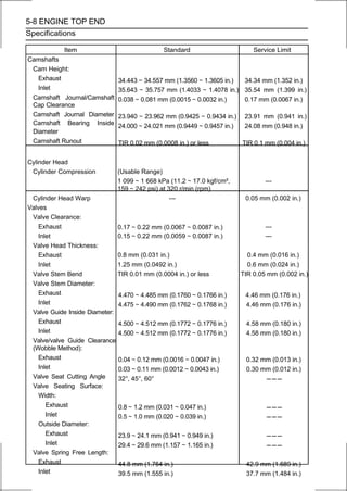

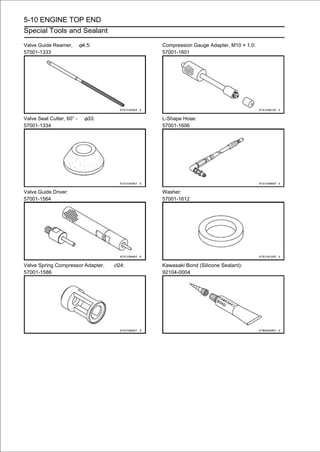
![ENGINE TOP END 5-11
Clean Air System
Air Suction Valve Removal
• Remove:
Air Switching Valve (see Air Switching Valve Removal)
Air Suction Valve Cover Bolts [A] (Both Sides)
Air Suction Valve Covers [B] (Both Sides)
• Remove the air suction valves [A] on both sides.
Air Suction Valve Installation
• Install the air suction valve so that opening [A] of the reed
faces the rear and downward.
• Apply a non-permanent locking agent to the threads of
the air suction valve cover bolts, and tighten them.
Torque - Air Suction Valve Cover Bolts: 10 N·m (1.0 kgf·m,
89 in·lb)
Air Suction Valve Inspection
• Remove the air suction valve (see Air Suction Valve Re-
moval).
• Visually inspect the reeds for cracks, folds, warps, heat
damage or other damage.
If there is any doubt as to the condition of the reeds [A],
replace the air suction valve as an assembly.
• Check the reed contact areas [B] of the valve holder for
grooves, scratches, any signs of separation from the
holder or heat damage.
• If there is any doubt as to the condition of the reed contact
areas, replace the air suction valve as an assembly.
• If any carbon or other foreign particles have accumulated
between the reed and the reed contact area, wash the
valve assembly clean with a high-flash point solvent.
CAUTION
Do not scrape off the deposits with a scraper as this
could damage the rubber, requiring replacement of
the suction valve assembly.](https://image.slidesharecdn.com/2008-100321201635-phpapp01/85/2008-282-320.jpg)
![5-12 ENGINE TOP END
Clean Air System
Air Switching Valve Removal
CAUTION
Never drop the air switching valve, especially on a
hard surface. Such a shock to the air switching
valve can damaged it.
• Remove the middle air cleaner housing chapter). Cleaner
Housing Removal in the Fuel System (DFI)
(see Air
• Disconnect the connector [A].
• Separate the hoses [B] from the air suction valve covers
and lower air cleaner housing, and remove the air switch-
ing valve [C].
Air Switching Valve Installation
• Install the air switching valve [A] with hose [B] as shown in
the figure.
Front [C]
Left Side View [D]
Air Switching Valve Operation Test
• Refer to the Air Suction System Damage Inspection in the
Periodic Maintenance chapter.
Air Switching Valve Unit Test
• Refer to the Air Switching Valve Unit Test in the Electrical
System chapter.
Clean Air System Hose Inspection
• Be certain that all the hoses are routed without being flat-
tened or kinked, and are connected correctly to the air
cleaner housing, air switching valve and air suction valve
covers.
If they are not, correct them. Replace them if they are
damaged.](https://image.slidesharecdn.com/2008-100321201635-phpapp01/85/2008-283-320.jpg)
![ENGINE TOP END 5-13
Cylinder Head Cover
Cylinder Head Cover Removal
•Remove:
Air Suction Valves (see Air Suction Valve Removal)
Throttle Body Assy (see Throttle Body Assy Removal in
the Fuel System (DFI) chapter)
Stick Coils (see Stick Coil Removal in the Electrical System
chapter)
• Remove the radiator [A] temporarily (see Radiator and
Radiator Fan Removal in the Cooling System chapter),
and then free the heat insulation rubber plate [B].
NOTE
○Do not remove radiator hoses.
• Remove the cylinder head cover bolts [C] with rubber
washers.
• Remove the cylinder head cover [D] forward.
Cylinder Head Cover Installation
• Replace the cylinder head cover gasket [A] with a new
one.
• Apply silicone sealant [B] to the cylinder head as shown in
the figure.
Sealant - Kawasaki Bond (Silicone Sealant): 92104-0004
• Be sure to install the following parts.
Dowel Pins [A]
Plug Hole Gaskets [B]](https://image.slidesharecdn.com/2008-100321201635-phpapp01/85/2008-284-320.jpg)
![5-14 ENGINE TOP END
Cylinder Head Cover
• Install the rubber washers [A] with the metal side faces
upward.
• Tighten:
Torque - Cylinder Head Cover Bolts: 10 N·m (1.0 kgf·m, 89
in·lb)
• Install the removed parts (see appropriate chapters).](https://image.slidesharecdn.com/2008-100321201635-phpapp01/85/2008-285-320.jpg)
![ENGINE TOP END 5-15
Camshaft Chain Tensioner
Camshaft Chain Tensioner Removal
CAUTION
This is a non-return type camshaft chain tensioner.
The push rod does not return to its original position
once it moves out to take up camshaft chain slack.
Observe all the rules listed below:
When removing the tensioner, do not take out the
mounting bolts only halfway. Retightening the
mounting bolts from this position could damage
the tensioner and the camshaft chain. Once the
bolts are loosened, the tensioner must be removed
and reset as described in "Camshaft Chain Ten-
sioner Installation."
Do not turn over the crankshaft while the tensioner is
removed. This could upset the camshaft chain
timing, and damage the valves.
• Drain the coolant (see Coolant Change in the Periodic
Maintenance chapter).
• RemoveRemoval in the Frame chapter).(see Upper Fairing
Assembly
the upper fairing assembly
• Remove theitradiator hose [A] from the radiator pipe [B],
and then clear backward.
• Remove:
Cap Bolt [A]
Washer [B]
• Remove:
Spring [A]
Rod [B]](https://image.slidesharecdn.com/2008-100321201635-phpapp01/85/2008-286-320.jpg)
![5-16 ENGINE TOP END
Camshaft Chain Tensioner
• Remove the body [B]. bolts [A] and take off the camshaft
chain tensioner
mounting
Camshaft Chain Tensioner Installation
• Replace the O-ring [A] with a new one.
• Apply grease to the new O-ring.
• Release the stopper [B] and push the push rod [C] into the
interior of the tensioner body [D] so that the position of the
push rod is 3 or 4 notches [E] as shown in the figure.
About 15.6 mm (0.614 in.) [F]
• Install the tensioner body so that the stopper faces up-
ward.
• Tighten the tensioner mounting bolts [A].
Torque - Camshaft Chain Tensioner Mounting Bolts: 10
N·m (1.0 kgf·m, 89 in·lb)
• Install:
Rod [B]
Spring [C]
Washer [D]
• Tighten the cap bolt [E].
Torque - Camshaft Chain Tensioner Cap Bolt: 20 N·m (2.0
kgf·m, 15 ft·lb)
• Run the radiator hose correctly (see Cable, Wire, and
hose Routing section in the Appendix chapter).
• Tighten:
Torque - Water Hose Clamp Screw: 2.0 N·m (0.20 kgf·m, 18
in·lb)
• Fill theMaintenance chapter). (see Coolant Change in the
Periodic
radiator with coolant](https://image.slidesharecdn.com/2008-100321201635-phpapp01/85/2008-287-320.jpg)
![ENGINE TOP END 5-17
Camshaft, Camshaft Chain
Camshaft Removal
• Remove the cylinder head cover (see Cylinder Head
Cover Removal).
• Remove the timing inspection cap [A] and starter clutch
bolt cap [B] on the starter clutch cover [C].
• Using aclockwiseon the starter clutch mark[A], #1,4 the
crankshaft
wrench
until the line [B] (TDC
bolt
for
turn
pistons) on the starter clutch is aligned with the notch [C] in
the edge of the timing inspection hole [D] in the starter
clutch cover.
If the starter clutch cover was removed, perform the next
procedure.
○Using a wrench on the starter clutch bolt [A], turn the
crankshaft clockwise until the line [B] (TDC mark for #1,4
pistons) on the starter clutch [C] is aligned with the mating
surface [D] of the crankcase.](https://image.slidesharecdn.com/2008-100321201635-phpapp01/85/2008-288-320.jpg)
![5-18 ENGINE TOP END
Camshaft, Camshaft Chain
• Remove the Removal). chain tensioner (see Camshaft
Chain Tensioner
camshaft
• Loosen the upper chain ∼ 20] inboltsfigure,camshaft cap
bolts as shown sequence [1
guide
the
and
and re-
move them.
• Remove:
Upper Chain Guide [A]
Camshaft Caps [B]
Camshafts [C]
• Stuff a clean cloth into the chain tunnel to keep any parts
from dropping into the crankcase.
• Remove:
Cam Sprocket Mounting Bolts [A]
Cam Sprockets [B]
CAUTION
The crankshaft may be turned while the camshafts
are removed. Always pull the chain taut while turn-
ing the crankshaft. This avoids kinking the chain
on the lower (crankshaft) sprocket. A kinked chain
could damage both the chain and the sprocket.
Camshaft Installation
•Be sure to install the following parts.
Plug Hole Gaskets [A]
Dowel Pins [B]](https://image.slidesharecdn.com/2008-100321201635-phpapp01/85/2008-289-320.jpg)
![ENGINE TOP END 5-19
Camshaft, Camshaft Chain
NOTE
○The exhaust camshaft has a 2310 EX mark [A] and the
inlet camshaft has a 2310 IN mark [B]. Be careful not to mix
up these shafts.
○The exhaust camshaft has the projection [C] for
camshaft position sensor.
• Install thePositions [A] as shown in the figure.
#4 Cam
cam sprockets
Inlet Cam Sprocket [B]
Exhaust Cam Sprocket [C]
○The inlet cam sprocket and exhaust cam sprocket are
identical.
• Apply a non-permanent locking agent to the threads of
the cam sprocket mounting bolts and tighten them.
Torque - Cam Sprocket Mounting Bolts: 15 N·m (1.5 kgf·m,
11 ft·lb)
• Apply molybdenum disulfide oil solution to all cam parts
and journals.
If a new camshaft is to be used, apply a thin coat of
molybdenum disulfide grease to the cam surfaces.
• Using aclockwiseon the starter clutch mark[A], #1,4 the
crankshaft
wrench
until the line [B] (TDC
bolt
for
turn
pistons) on the starter clutch is aligned with the notch [C] in
the edge of the timing inspection hole [D] in the starter
clutch cover.
CAUTION
The crankshaft may be turned while the camshafts
are removed. Always pull the chain taut while turn-
ing the crankshaft. This avoids kinking the chain
on the lower (crankshaft) sprocket. A kinked chain
could damage both the chain and the sprocket.](https://image.slidesharecdn.com/2008-100321201635-phpapp01/85/2008-290-320.jpg)
![5-20 ENGINE TOP END
Camshaft, Camshaft Chain
If the starter clutch cover was removed, perform the next
procedure.
○Using a wrench on the starter clutch bolt [A], turn the
crankshaft clockwise until the line [B] (TDC mark for #1,4
pistons) on the starter clutch [C] is aligned with the mating
surface [D] of the crankcase.
• Pull the chain. side (exhaust side) [A] of the chain taut to
install
the tension
• Engageon the sprockets are positionedsprockets so the tim-
ing marks
the camshaft chain with the
as shown in
that
figure.
○The Timing marks must be aligned with the cylinder head
upper surface [B].
EX mark [C]
IN mark [D]
#1 pin [E]
#2 pin [F]
#27 pin [G]
#28 pin [H]](https://image.slidesharecdn.com/2008-100321201635-phpapp01/85/2008-291-320.jpg)
![ENGINE TOP END 5-21
Camshaft, Camshaft Chain
• Before installing the camshafttensioner body tem-
guide, install the camshaft chain
caps and upper chain
porarily (see Camshaft Chain Tensioner Installation).
• Install the camshaft caps and upper camshaft chain guide [A]
as shown in the figure.
Identification No. 1 ∼ 4 (Camshaft Cap) [B]
Identification No. 1 ∼ 4 (Cylinder Head) [C]
• First tighten the camshaft cap bolt [17, 18] and upper
chain guide bolts [19, 20] evenly to seat the camshaft in
place, then tighten all bolts following the specified
tightening sequence.
Torque - Camshaft Cap Bolts [1 ∼ 18]: 12 N·m (1.2 kgf·m,
106 in·lb)
Upper Camshaft Chain Guide Bolts [19, 20]: 12
N·m (1.2 kgf·m, 106 in·lb)
• Install the camshaft chain tensioner (see Camshaft Chain
Tensioner Installation).
• Turntothe crankshaft 2 turns clockwise chain timing. ten-
sioner expand and recheck the camshaft
to allow the
• Replacecap with newof the timing inspection cap and starter
clutch bolt
the O-ring
ones.
• Apply grease to the new O-rings.
• Install the timing inspection cap and starter clutch bolt
cap.
• Tighten:
Torque - Timing Inspection Cap: Hand-tighten
Starter Clutch Bolt Cap: Hand-tighten
• Install the cylinder head cover (see Cylinder Head Cover
Installation).](https://image.slidesharecdn.com/2008-100321201635-phpapp01/85/2008-292-320.jpg)
![5-22 ENGINE TOP END
Camshaft, Camshaft Chain
Camshaft, Camshaft Cap Wear
• Remove the camshaft cap (see Camshaft Removal).
• Cut strips of plastigage to journal width. Place a strip
on each journal parallel to the camshaft installed in the
correct position.
• Tighten the camshaft cap bolts and upper chain guide
bolts to the specified torque (see Camshaft Installation).
NOTE
○Do not turn the camshaft when the plastigage is
between the journal and camshaft cap.
• Remove the camshaft cap again, the camshaft capclear-
ance between the camshaft journal and
measure each
using plastigage (press gauge) [A].
Camshaft Journal/Camshaft Cap Clearance
Standard: 0.038 ∼ 0.081 mm (0.0015 ∼ 0.0032 in.)
Service Limit: 0.17 mm (0.0067 in.)
If any clearance exceeds the service limit, measure the
diameter of each camshaft journal with a micrometer.
Camshaft Journal Diameter
Standard: 23.940 ∼ 23.962 mm (0.9425 ∼ 0.9434 in.)
Service Limit: 23.91 mm (0.941 in.)
If the camshaft journal diameter is less than the service
limit, replace the camshaft with a new one and measure the
clearance again.
If the clearance still remains out of the limit, replace the
cylinder head unit.
Camshaft Runout
• Remove the camshaft (see Camshaft Removal).
• Set the camshaft in a camshaft alignment jig or on V
blocks.
• Measure runout with a dial gauge at the specified place as
shown.
If the runout exceeds the service limit, replace the shaft.
Camshaft Runout
Standard: TIR 0.02 mm (0.0008 in.) or less
Service Limit: TIR 0.1 mm (0.004 in.)
Cam Wear
• Remove the camshaft (see Camshaft Removal).
• Measure the height [A] of each cam with a micrometer.
If the cams are worn down past the service limit, replace
the camshaft.
Cam Height
Standard:
Exhaust 34.443 ∼ 34.557 mm (1.3560 ∼ 1.3605 in.)
Inlet 35.643 ∼ 35.757 mm (1.4033 ∼ 1.4078 in.)
Service Limit:
Exhaust 34.34 mm (1.352 in.)
Inlet 35.54 mm (1.399 in.)](https://image.slidesharecdn.com/2008-100321201635-phpapp01/85/2008-293-320.jpg)
![ENGINE TOP END 5-23
Camshaft, Camshaft Chain
Camshaft Chain Removal
• Split the crankcase (see Crankcase Splitting in the
Crankshaft/Transmission chapter).
• Remove the camshaft chain [A] from the crankshaft
sprocket.](https://image.slidesharecdn.com/2008-100321201635-phpapp01/85/2008-294-320.jpg)
![5-24 ENGINE TOP END
Cylinder Head
Cylinder Compression Measurement
NOTE
○Use the battery which is fully charged.
• Warm up the engine thoroughly.
• Stop the engine.
• Remove spark plugs (see Spark Plug Replacement in the
Periodic Maintenance chapter).
• Attach the compression gauge [A] and adapter [B] firmly
into the spark plug hole.
○Using the starter motor, turn the engine over with the throttle
fully open until the compression gauge stops rising; the
compression is the highest reading obtainable.
Special Tools - Compression Gauge, 20 kgf/cm²: 57001-221
Compression Gauge Adapter, M10 × 1.0:
57001-1601
L-Shape Hose: 57001-1606
Cylinder Compression
Usable Range: 1 099 ∼ 1 668 kPa (11.2 ∼ 17.0 kgf/cm²,
159 ∼ 242 psi) at 320 r/min (rpm)
• Repeat the measurement for the other cylinders.
• Install theMaintenance chapter). Plug Replacement in
the Periodic
spark plugs (see Spark
The following table should be consulted if the obtainable compression reading is not within the
usable range.
Problem Diagnosis Remedy (Action)
Cylinder Carbon accumulation on piston and in Remove the carbon deposits and
compression combustion chamber possibly due to replace damaged parts if necessary.
is higher than damaged valve stem oil seal and/or
usable range damaged piston oil rings (This may be
indicated by white exhaust smoke).
Incorrect cylinder head gasket thickness Replace the gasket with a standard part.
Cylinder Gas leakage around cylinder head Replace damaged check gasket and
compression cylinder head warp.
is lower than
Bad condition of valve seating Repair if necessary.
usable range
Incorrect valve clearance Adjust the valve clearance.
Incorrect piston/cylinder clearance Replace the piston and/or cylinder.
Piston seizure Inspect the cylinder and replace/repair
the cylinder and/or piston as necessary.
Bad condition of piston ring and/or piston Replace the piston and/or the piston
ring grooves rings.](https://image.slidesharecdn.com/2008-100321201635-phpapp01/85/2008-295-320.jpg)
![ENGINE TOP END 5-25
Cylinder Head
Cylinder Head Removal
• Drain the coolant (see Coolant Change in the Periodic
Maintenance chapter).
•Remove:
Throttle Body Assy (see Throttle Body Assy Removal in
the Fuel System (DFI) chapter)
Exhaust Manifold (see Exhaust Manifold Removal)
Camshafts (see Camshaft Removal)
Crankshaft Sensor (see Crankshaft Sensor Removal in
the Electrical System chapter)
Starter Clutch (see Starter Clutch Removal in the
Crankshaft/Transmission chapter)
Left and Right Front Engine Mounting Bolts (see Engine
Removal in the Engine Removal/Installation chapter)
• Disconnect the water temperature sensor connector [A].
• Remove the front camshaft chain guide bolt (upper) [A].
• Remove:
Front Camshaft Chain Guide Bolt (Lower) [A]
Collar
Front Camshaft Chain Guide [B]](https://image.slidesharecdn.com/2008-100321201635-phpapp01/85/2008-296-320.jpg)
![5-26 ENGINE TOP END
Cylinder Head
• Loosen [1 ∼ 12] in theM10 cylinder head bolts as shown
sequence
the M6 and
figure, and remove them with
washers.
• Remove the cylinder head forward.
Cylinder Head Installation
NOTE
○The camshaft cap is machined with the cylinder head,
so if a new cylinder head is installed, use the cap that is
supplied with the new head.
If the right engine bracket (cylinder head) [A] was
removed, install it as follows.
○Apply a non-permanent locking agent to the threads of the
right engine bracket bolts (cylinder head) [B].
○Install the clamp [C] so that it becomes straight to the bolt
holes [D] of the bracket.
○Tighten:
Torque - Right Engine Bracket Bolts (Cylinder Head): 9.8
N·m (1.0 kgf·m, 87 in·lb)
• Install the dowel pins.
• Replace the cylinder head gasket with a new one.
• Replace the cylinder head bolt washers [A] with new ones.
• Apply molybdenum disulfide oiland the threads ofsides [B]
of the cylinder head bolt washers
solution to both
the
head bolts [C].
• Install side left faces outward. (cylinder head) [A] so that
the boss
the
[B]
engine bracket
Front [C]](https://image.slidesharecdn.com/2008-100321201635-phpapp01/85/2008-297-320.jpg)
![ENGINE TOP END 5-27
Cylinder Head
• Tightenfigure. cylinder head bolts as shown sequence [1 ∼
10] in the
the M10
Torque - Cylinder Head Bolts (M10):
First: 20 N·m (2.0 kgf·m, 15 ft·lb)
Final (New Bolts): 59 N·m (6.0 kgf·m, 44 ft·lb)
Final (Used Bolts): 57 N·m (5.8 kgf·m, 42 ft·lb)
• 12] in the figure.cylinder head bolts as shown sequence [11
∼
Tighten the M6
Torque - Cylinder Head Bolts (M6): 12 N·m (1.2 kgf·m, 106
in·lb)
• Install:
Left and Right Front Engine Mounting Bolts (see Engine
Removal in the Engine Removal/Installation chapter)
Front Camshaft Chain Guide [A]
New O-ring [B]
Collar [C]
○Apply grease to the new O-ring.
•Tighten:
Torque - Front Camshaft Chain Guide Bolt (Upper) [D]: 25
N·m (2.5 kgf·m, 18 ft·lb)
Front Camshaft Chain Guide Bolt (Lower) [E]: 12
N·m (1.2 kgf·m, 106 in·lb)
• Install the removed parts (see appropriate chapters).
Cylinder Head Warp
• Clean the cylinder head.
• Lay a straightedge across the lower surface of the cylinder
head at several positions.
• Use a thickness gauge [A] to measure the space between the
straightedge [B] and the head.
Cylinder Head Warp
Standard: ---
Service Limit: 0.05 mm (0.002 in.)
If the cylinder head is warped more than the service limit,
replace it.
If the cylinder head is warped less than the service limit,
repair the head by rubbing the lower surface on emery
paper secured to a surface plate (first No. 200, then No.
400).](https://image.slidesharecdn.com/2008-100321201635-phpapp01/85/2008-298-320.jpg)
![5-28 ENGINE TOP END
Valves
Valve Clearance Inspection
• Refer to the Valve Clearance Inspection in the Periodic
Maintenance chapter.
Valve Removal
• Remove the cylinder head (see Cylinder Head Removal).
• Remove the valve lifter and shim.
○Mark and record the valve lifter and shim locations so they
can be installed in their original positions.
• Using the valve spring compressor assembly, remove the
valve.
Special Tools - Valve Spring Compressor Assembly [A]:
57001-241
Valve Spring Compressor Adapter, 24 [B]:
57001-1586
Valve Installation
CAUTION
Do not lap the valve to the valve seat, using the
grinding compound. It will come off oxide film
treated surface of the valve.
• Replace the oil seal with a new one.
• Apply a thin coat of molybdenum disulfide grease to the
valve stem before valve installation.
○The inlet valves are larger than the exhaust valves.
• Install the springs so that the closed coil end faces down-
wards.
Valve Stem [A]
Oil Seal [B]
Spring Seat [C]
Closed Coil End [D]
Valve Spring [E]:
EX-Purple Paint
IN-Blue Paint
Retainer [F]
Split Keepers [G]
Valve Guide Removal
• Remove:
Valve (see Valve Removal)
Oil Seal
Spring Seat
• Heat the area around the valve guide to 120
∼ 150°C (248
∼ 302°F), and hammer lightly on the valve guide arbor [A]
to remove the guide from the top of the head.
CAUTION
Do not heat the cylinder head with a torch. This will
warp the cylinder head. Soak the cylinder head in oil
and heat the oil.
Special Tool - Valve Guide Arbor, 4.5: 57001-1331](https://image.slidesharecdn.com/2008-100321201635-phpapp01/85/2008-299-320.jpg)
![ENGINE TOP END 5-29
Valves
Valve Guide Installation
• Apply oil to the valve guide outer surface before installa-
tion.
• Heat the area around the valve guide hole to about 120
150°C (248 ∼ 302°F).
∼
CAUTION
Do not heat the cylinder head with a torch. This Will
warp the cylinder head. Soak the cylinder head and
heat the oil.
• Using the valve guide driver [A] and washer [B], press
and insert the valve guide in until the valve guide driver
surface [C] touches the head surface [D].
13.3 ∼ 13.5 mm (0.52 ∼ 0.53 in.) [E]
Special Tools - Valve Guide Driver: 57001-1564
Washer: 57001-1612
• Ream the valve guide with valve guide reamer [A], even if
the old guide is reused.
Special Tool - Valve Guide Reamer, 4.5: 57001-1333
Valve-to-Guide Clearance Measurement (Wobble
Method)
If a small bore gauge is not available, inspect the valve
guide wear by measuring the valve to valve guide clearance
with the wobble method as indicated below.
• Insert a new valve [A] into the guide [B] and set a dial
gauge against the stem perpendicular to it as close as
possible to the cylinder head mating surface.
• Move the stem back and forth [C] to measure valve/valve
guide clearance.
• Repeat the measurement in a direction at a right angle to
the first.
If the reading exceeds the service limit, replace the guide.](https://image.slidesharecdn.com/2008-100321201635-phpapp01/85/2008-300-320.jpg)
![5-30 ENGINE TOP END
Valves
NOTE
○The reading is not actual valve/valve guide clearance
because the measuring point is above the guide.
Valve/Valve Guide Clearance (Wobble Method)
Standard:
Exhaust 0.04 ∼ 0.12 mm (0.0016 ∼ 0.0047 in.)
Inlet 0.03 ∼ 0.11 mm (0.0012 ∼ 0.0043 in.)
Service Limit:
Exhaust 0.32 mm (0.013 in.)
Inlet 0.30 mm (0.012 in.)
Valve Seat Inspection
• Remove the valve (see Valve Removal).
• Check the valve seating surface [A] between the valve [B]
and valve seat [C].
○Measure the outside diameter [D] of the seating pattern on
the valve seat.
If the outside diameter is too large or too small, repair the
seat (see Seat Repair).
Valve Seating Surface Outside Diameter
Standard:
Exhaust 23.9 ∼ 24.1 mm (0.941 ∼ 0.949 in.)
Inlet 29.4 ∼ 29.6 mm (1.157 ∼ 1.165 in.)
○Measure the seat width [E] of the portion where there is no
build-up carbon (white portion) of the valve seat with a vernier
caliper.
Good [F]
If the width is too wide [G], too narrow [H] or uneven [J],
repair the seat (see Valve Seat Repair).
Valve Seating Surface Width
Standard:
Exhaust 0.8 ∼ 1.2 mm (0.031 ∼ 0.047 in.)
Inlet 0.5 ∼ 1.0 mm (0.020 ∼ 0.039 in.)
Valve Seat Repair
• Repair the valve seat with the valve seat cutters [A].
Special Tools - Valve Seat Cutter Holder Bar: 57001-1128
[C]
Valve Seat Cutter Holder, 4.5: 57001-1330
[B]
[For Exhaust Valve Seat]
Valve Seat Cutter, 45° - 27.5: 57001-1114
Valve Seat Cutter, 32° - 28: 57001-1119
Valve Seat Cutter, 60° - 25: 57001-1328
[For Inlet Valve Seat]
Valve Seat Cutter, 45° - 32: 57001-1115
Valve Seat Cutter, 32° - 33: 57001-1199
Valve Seat Cutter, 60° - 33: 57001-1334
If the manufacturer’s instructions are not available, use
the following procedure.](https://image.slidesharecdn.com/2008-100321201635-phpapp01/85/2008-301-320.jpg)
![ENGINE TOP END 5-31
Valves
Seat Cutter Operation Care
1. This valve seat cutter is developed to grind the valve for
repair. Therefore the cutter must not be used for other
purposes than seat repair.
2. Do not drop or shock the valve seat cutter, or the dia-
mond particles may fall off.
3. Do not fail to apply engine oil to the valve seat cutter
before grinding the seat surface. Also wash off ground
particles sticking to the cutter with washing oil.
NOTE
○Do not use a wire brush to remove the metal particles
from the cutter. It will take off the diamond particles.
4. Setting the valve seat cutter holder in position, operate
the cutter in one hand. Do not apply too much force to
the diamond portion.
NOTE
○Prior to grinding, apply engine oil to the cutter and during
the operation, wash off any ground particles sticking to the
cutter with washing oil.
5. After use, wash it with washing oil and apply thin layer
of engine oil before storing.
Marks Stamped on the Cutter
The marks stamped on the back of the cutter [A] represent the
following.
60° ........................... Cutter angle [B]
37.5.......................... Outer diameter of cutter [C]
Operating Procedures
• Clean the seat area carefully.
• Coat the seat with machinist’s dye.
• Fit a 45° cutter into the holder and slide it into the valve
guide.
• Press down lightly on onlyhandle is smooth.it right or left.
Grind the seating surface
the
until it
and turn
CAUTION
Do not grind the seat too much. Overgrinding will
reduce valve clearance by sinking the valve into the
head. If the valve sinks too far into the head, it will
be impossible to adjust the clearance, and the cylinder
head must be replaced.](https://image.slidesharecdn.com/2008-100321201635-phpapp01/85/2008-302-320.jpg)
![5-32 ENGINE TOP END
Valves
• Measure the outside diameter of the seating surface with a
vernier caliper.
If the outside diameter of the seating surface is too small,
repeat the 45° grind until the diameter is within the spec-
ified range.
Widened Width [A] of engagement by machining with
45° cutter
Ground Volume [B] by 32° cutter
32° [C]
Correct Width [D]
Ground Volume [E] by 60° cutter
60° [F]
• Measure the outside diameter of the seating surface with a
vernier caliper.
If the outside diameter of the seating surface is too small,
repeat the 45° grind [A] until the diameter is within the
specified range.
Original Seating Surface [B]
NOTE
○Remove all pittings of flaws from 45° ground surface.
○After grinding with 45° cutter, apply thin coat of machin-
ist’s dye to seating surface. This makes seating surface
distinct and 32° and 60° grinding operation easier.
○When the valve guide is replaced, be sure to grind with
45° cutter for centering and good contact.
If the outside diameter [A] of the seating surface is too
large, make the 32° grind described below.
If the outside diameter of the seating surface is within the
specified range, measure the seat width as described be-
low.
• Grind the seat at a 32° angle [B] until the seat O.D. is
within the specified range.
○To make the 32° grind, fit a 32° cutter into the holder, and
slide it into the valve guide.
○Turn the holder one turn at a time while pressing down
very lightly. Check the seat after each turn.
CAUTION
The 32° cutter removes material very quickly.
Check the seat outside diameter frequently to
prevent overgrinding.
○After making the 32° grind, return to the seat O.D.
measurement step above.
• To measure the seat width, use a vernier caliper to mea-
sure the width of the 45° angle portion of the seat at sev-
eral places around the seat.
If the seat width is too narrow, repeat the 45° grind until
the seat is slightly too wide, and then return to the seat
O.D. measurement step above.](https://image.slidesharecdn.com/2008-100321201635-phpapp01/85/2008-303-320.jpg)
![ENGINE TOP END 5-33
Valves
If the seat width is too wide, make the 60° [A] grind
described below.
If the seat width is within the specified range, lap the valve to
the seat as described below.
• Grind the seat at a 60° angle until the seat width is within
the specified range.
○To make the 60° grind, fit 60° cutter into the holder, and
slide it into the valve guide.
○Turn the holder, while pressing down lightly.
○After making the 60° grind, return to the seat width
measurement step above.
Correct Width [B]
CAUTION
Do not lap the valve to the valve seat, using the
grinding compound. It will come off oxide film
treated surface of the valve.
• When the engine is assembled, be sureintothe Periodic valve
clearance (see Valve Clearance Inspection
adjust the
Maintenance chapter).](https://image.slidesharecdn.com/2008-100321201635-phpapp01/85/2008-304-320.jpg)
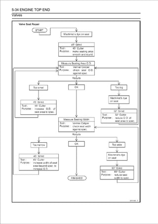
![ENGINE TOP END 5-35
Throttle Body Assy Holder
Throttle Body Assy Holder Removal
• Remove:
Throttle Body Assy (Throttle Body Assy Removal in the
Fuel System (DFI) chapter)
Clamps [A]
• Loosen the throttle body assy holder bolts as shown
sequence [1 ∼ 3] in the figure, and remove them.
• Remove the throttle body assy holders [B].
Throttle Body Assy Holder Installation
• Be sure to install the new O-rings [A].
• Apply grease to the new O-ring.
• Install the clamps [B] as shown in the figure.
• Tighten the holder bolts as shown sequence [1
figure.
∼ 3] in the
Torque - Throttle Body Assy Holder Bolts [C]: 10 N·m (1.0
kgf·m, 89 in·lb)
Throttle Body Assy Holder Clamp Bolts [D]: 2.0
N·m (0.20 kgf·m, 18 in·lb)
Upside View [E]](https://image.slidesharecdn.com/2008-100321201635-phpapp01/85/2008-306-320.jpg)
![5-36 ENGINE TOP END
Muffler
WARNING
To avoid a serious burn, do not remove the muffler
when the engine is still hot. What until the muffler
cool down.
Muffler Body Removal
• Remove the front seat (see Front Seat Removal in the
Frame chapter).
• Open the clamp [A] and free the cables.
• Slide the dust covers [B].
• Loosento the locknuts plenty of play.
clockwise give the cable
[A], and turn the adjusters [B]
• Remove the lower ends of thebody (see butterfly valve ca-
bles from the pulley of the muffler
exhaust
Exhaust But-
terfly Valve Cable Removal).
• Loosen the muffle body clamp bolt [A].
• Remove the muffler body mounting bolt [B], and pull out
the muffler body [C] backward from the premuffler cham-
ber.](https://image.slidesharecdn.com/2008-100321201635-phpapp01/85/2008-307-320.jpg)
![ENGINE TOP END 5-37
Muffler
Muffler Body Installation
If the muffler body front [A] and rear [B] covers were
removed, install them.
Torque - Muffler Body Front Cover Bolts [C]: 7.0 N·m (0.71
kgf·m, 62 in·lb)
Muffler Body Rear Cover Bolts [D]: 7.0 N·m (0.71
kgf·m, 62 in·lb)
• Replace the muffler body gasket [E] with a new one.
• Installitthebottomedbody gasketchamferpremuffler chamber
[F] until is
muffler
so that the
to the
side [G] faces
muffler body [H].
About 4.0 mm (0.16 in.) [I]
• Insert the projectionbodyinto the slotas shown in the figure.
○
Install the muffler
[K]
clamp [J]
[L].
Rear View [M]
• Tighten:
Torque - Muffler Body Mounting Bolt [N]: 25 N·m (2.5 kgf·m,
18 ft·lb)
Muffler Body Clamp Bolt [O]: 25 N·m (2.5 kgf·m, 18
ft·lb)](https://image.slidesharecdn.com/2008-100321201635-phpapp01/85/2008-308-320.jpg)
![5-38 ENGINE TOP END
Muffler
• Install adjust the cables of the exhaust butterfly valve ca-
bles, and
the lower ends
correctly (see Exhaust Butter-
fly Valve Cable Installation).
• Thoroughly warm up the engine, wait until the engine
cools down, retighten all the bolts and nuts.
Premuffler Chamber Removal
• Remove:
Muffler Body (see Muffler Body Removal)
Bolts [A]
Premuffler Chamber Outer Cover [B]
• Loosen the exhaust manifold clamp bolt [A].
• Remove premuffler chamber [C] backward from the and
pull out the
the premuffler chamber mounting bolt [B],
exhaust manifold.
Premuffler Chamber Installation
If the premuffler chamber inner cover [A] was removed,
install it as follows.
○Insert the projection [B] of the premuffler chamber [C] into the
slot of the damper [D].
○Tighten:
Torque - Premuffler Chamber Inner Cover Bolts [E]: 7.0
N·m (0.71 kgf·m, 62 in·lb)
• Replace the exhaust manifold gasket [F] with a new one.
• Install until it is bottomed so that the chamfer side [G]
chamber
the exhaust manifold gasket to the premuffler
faces exhaust manifold [H].
About 4.0 mm (0.16 in.) [I]
• Install the exhaust manifold clamp [J] as shown in the
figure.
○Insert the projection [K] into the slot [L].
Front View [M]
• Install the nut [N] on the frame as shown in the figure.
• Tighten:
Torque - Premuffler Chamber Mounting Bolt [O]: 25 N·m
(2.5 kgf·m, 18 ft·lb)
Exhaust Manifold Clamp Bolt [P]: 25 N·m (2.5
kgf·m, 18 ft·lb)
• Install the premuffler chamber outer cover [Q].
Torque - Premuffler Chamber Outer Cover Bolts [R]: 7.0
N·m (0.71 kgf·m, 62 in·lb)](https://image.slidesharecdn.com/2008-100321201635-phpapp01/85/2008-309-320.jpg)
![ENGINE TOP END 5-39
Muffler
• Install the muffler body (see Muffler Body Installation).
• Thoroughly warm all the bolts and nuts. until the engine
cools down, retighten
up the engine, wait
Exhaust Manifold Removal
• For models equipped with oxygen sensors, disconnect
the oxygen sensor lead connectors [A], and then open the
clamp of the oil pan and free the oxygen sensor leads.](https://image.slidesharecdn.com/2008-100321201635-phpapp01/85/2008-310-320.jpg)
![5-40 ENGINE TOP END
Muffler
• Remove:
Radiator (see Radiator and Radiator Fan Removal in the
Cooling System chapter)
Bolts [A]
Premuffler Chamber Outer Cover [B]
• Loosen the exhaust manifold clamp bolt [A].
• Remove the exhaust pipe holder nuts [A],chamber. out the
exhaust manifold forward from the premuffler
and pull
Exhaust Manifold Installation
• Replace the exhaust pipe gaskets [A] with new ones.
• Replace the exhaust manifold gasket [B] with a new one.
• Install the exhaust manifold gasket to the premuffler
chamber [C] until it is bottomed so that the chamfer side
[D] faces exhaust manifold [E].
About 4.0 mm (0.16 in.) [F]
• Install the exhaust manifold clamp [G] as shown in the
figure.
○Insert the projection [H] into the slot [I].
Front View [J]
• Tighten:
Torque - Exhaust Pipe Holder Nuts [K]: 17 N·m (1.7 kgf·m,
13 ft·lb)
Exhaust Manifold Clamp Bolt [L]: 25 N·m (2.5
kgf·m, 18 ft·lb)
• Install the premuffler chamber outer cover [M].
Torque - Premuffler Chamber Outer Cover Bolts [N]: 7.0
N·m (0.71 kgf·m, 62 in·lb)](https://image.slidesharecdn.com/2008-100321201635-phpapp01/85/2008-311-320.jpg)
![ENGINE TOP END 5-41
Muffler
• Install the removed parts (see appropriate chapters).
○For models equipped with oxygen sensors, run the oxygen
sensor leads correctly (see Cable, Wire, and Hose Routing
section in the Appendix chapter).
• Thoroughly warm up the engine, wait until the engine
cools down, retighten all the bolts and nuts.
Exhaust Butterfly Valve Cable Removal
• Remove the front seat (see Front Seat Removal in the
Frame chapter).
• Open the clamp [A] and free the cables.
• Slide the dust covers [B].](https://image.slidesharecdn.com/2008-100321201635-phpapp01/85/2008-312-320.jpg)
![5-42 ENGINE TOP END
Muffler
• Loosento the locknuts plenty of play.
clockwise give the cable
[A], and turn the adjusters [B]
• Remove the clamp [A].
• Remove the upper [C]. [B] of the exhaust butterfly valve
cables from the pulley
ends
• Remove:
Bolts [A]
Exhaust Butterfly Valve Pulley Cover [B]
• Loosen the locknuts [A].
• Remove the lower ends [B] of the exhaust butterfly valve
cables from the pulley [C].
• Pull the exhaust butterfly valve cables out of the frame.](https://image.slidesharecdn.com/2008-100321201635-phpapp01/85/2008-313-320.jpg)
![ENGINE TOP END 5-43
Muffler
Exhaust Butterfly Valve Cable Installation
•Confirm whether pulley [A] is an angle shown in the figure.
41.7° ±7° [B]
○This position is original position of the pulley.
NOTE
○Correct the position electrically after confirming use is
discontinued and there is no damage when differing from
the angle of shown in the figure.
CAUTION
Do not correct the pulley position with the tool,
forcibly. The actuator damage will occur.
If the angle is wrong, adjust the pulley (see Exhaust But-
terfly Valve Actuator Installation in the Fuel System (DFI)
chapter).
• Run the exhaust butterfly valve cables correctly (see
Cable, Wire, and Hose Routing section in the Appendix
chapter).
• Install the lower ends of the exhaust butterfly valve cables
to the pulley of the muffler body as shown in the figure.
Open Cable (White) [A]
Close Cable (Black) [B]
Left Side View [C]
Front View [D]
Outside [E]
• Tighten the locknuts securely.
• Install the exhaust butterfly valve pulley cover.
Torque - Exhaust Butterfly Valve Pulley Cover Bolts: 7.0
N·m (0.71 kgf·m, 62 in·lb)](https://image.slidesharecdn.com/2008-100321201635-phpapp01/85/2008-314-320.jpg)
![5-44 ENGINE TOP END
Muffler
• Install the upper the exhaust butterfly valve actuator, ca-
bles to the pulley of
ends of the exhaust butterfly valve
following the specified installing sequence.
○First, install the close cable (black) [A].
○Second, install the open cable (white) [B].
○Third, install the clamp [C].
○Fourth, stretch the open cable (white) by using the
adjuster [D].
○Turn the adjuster counterclockwise until the play of the
open cable becomes no play.
CAUTION
To keep the correct exhaust butterfly valve position, be
sure to adjust the open cable first. Do not overstretch
the cable.
○Fifth, tighten the adjuster locknut (white) of the open cable
securely.
○Sixth, stretch the close cable (black) by using the adjuster
[E].
○Turn the adjuster counterclockwise until the play of the
close cable becomes no play.
○Seventh, turn the adjuster of the close cable (black) clockwise
by 1/2 to 1 rotation.
○Lastly, tighten the adjuster locknut (black) of the close
cable securely.
• After installation, cover the dust covers on the adjusters as
shown in the figure.
15 mm (0.59 in.) or less [F]
• Fix the exhaust butterfly valve cables with the clamp [G].](https://image.slidesharecdn.com/2008-100321201635-phpapp01/85/2008-315-320.jpg)
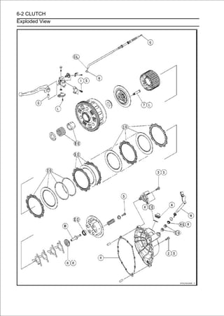
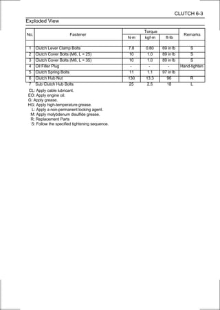
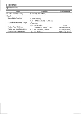
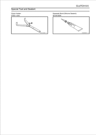
![6-6 CLUTCH
Clutch Lever and Cable
Clutch Lever Free Play Inspection
• Refer to the Clutch Operation Inspection in the Periodic
Maintenance chapter.
Clutch Lever Free Play Adjustment
• Refer to the Clutch Operation Inspection in the Periodic
Maintenance chapter.
Cable Removal
• Remove the right upper fairing cover (see Upper Fairing
Cover Removal in the Frame chapter).
• Slide the dust cover [A] at the clutch cable lower end out of
place.
• Loosen the nuts [B], and slide the lower end of the clutch
cable to give the cable plenty of play.
• Screw in the adjuster.
• Line upfree the cable from theclutch lever and adjuster [B],
and then
the slots [A] in the
lever.
• Free the clutch inner cable tip from the clutch release
lever.
• Push the release lever towardclutchfront ofto prevent
and tape the release lever to the
the
cover
the motorcycle
the release shaft from falling out.
• Pull the clutch cable out of the frame.
Cable Installation
• Run the clutch cable correctly (see Cable, Wire, and Hose
Routing section in the Appendix chapter).
• Adjust the clutch cable (see Clutch Operation Inspection in
the Periodic Maintenance chapter).
• Install the right upper fairing cover (see Upper Fairing
Cover Installation in the Frame chapter).
Cable Lubrication
• Refer to the Chassis Parts Lubrication in the Periodic
Maintenance chapter.
Clutch Lever Installation
• Install the clutch lever so that the mating surface [A] of the
clutch lever clamp is aligned with the punch mark [B] of
the handlebar.
• Tighten the upper clamp bolt first, and then the lower
clamp bolt.
○There will be a gap at the lower part of the clamp after
tightening.
Torque - Clutch Lever Clamp Bolts: 7.8 N·m (0.80 kgf·m, 69
in·lb)](https://image.slidesharecdn.com/2008-100321201635-phpapp01/85/2008-321-320.jpg)
![CLUTCH 6-7
Clutch Cover
Clutch Cover Removal
• Drain the engine oil (see Engine Oil Change in the Periodic
Maintenance chapter).
• Remove:
Right Lower Fairing (see Lower Fairing Removal in the
Frame chapter)
Clutch Cable Lower End [A] (see Cable Removal)
• Loosen the clutch cover mounting bolts as shown se-
quence [1 ∼ 10] in the figure, and remove them and the
bracket [B].
• Turn the clutch cover [B]. toward the rear as shown, and
remove the
release lever [A]
About 90° [C]
Clutch Cover Installation
• Apply silicone sealant to the area [A] where the mating
surface of the crankcase touches the clutch cover gasket.
Sealant - Kawasaki Bond (Silicone Sealant): 92104-0004
• Be sure that the dowel pins [B] are in position.
• Replace the clutch cover gasket with a new one.
• Install the bracket [A].
• Tighten[1 the clutch figure.
sequence ∼ 10] in the
cover mounting bolts as shown
Torque - Clutch Cover Bolts: 10 N·m (1.0 kgf·m, 89 in·lb)
L=25mm(0.98in.) [B]
L=35mm(1.38in.) [C]
• Install:
Clutch Cable Lower End (see Cable Installation)
Right Lower Fairing (see Lower Fairing Installation in the
Frame chapter)
Release Shaft Removal
CAUTION
Do not remove the clutch release lever and shaft
assembly unless it is absolutely necessary. If re-
moved, the oil seal replacement may be required.
• Remove the clutch cover (see Clutch Cover Removal).
• Pull the cover. lever and shaft assembly [A] straight out of
the clutch
release](https://image.slidesharecdn.com/2008-100321201635-phpapp01/85/2008-322-320.jpg)
![6-8 CLUTCH
Clutch Cover
Release Shaft Installation
• Apply high-temperature grease to the oil seal lips on the
upper ridge of the clutch cover.
• Apply oil to the needle bearings in the hole of the clutch
cover.
• Apply molybdenum disulfide grease to the pusher-holding
portion [A] on the release shaft.
• Install the washer [B] and spring [C].
• Insert the release shaft straight into the upper hole of the
clutch cover.
CAUTION
When inserting the release shaft, be careful not to
remove the spring of the oil seal.
• Fit the View [B] as shown in the figure.
Rear
spring [A]
Release Shaft [C]
Clutch Cover [D]
• Install the clutch cover (see Clutch Cover Installation).
Clutch Cover Disassembly
•Remove:
Clutch Cover (see Clutch Cover Removal)
Release Lever and Shaft Assembly (see Release Shaft
Removal)
Oil Seal [A]
Oil Filler Plug [B]
• Remove the needle bearings [A].](https://image.slidesharecdn.com/2008-100321201635-phpapp01/85/2008-323-320.jpg)
![CLUTCH 6-9
Clutch Cover
Clutch Cover Assembly
• Replace the needle bearings and oil seal with new ones.
NOTE
○Install the needle bearings so that the manufacture’s
make face out.
• Install the needle bearings [A] and oil seal [B] position as
shown.
○Press the lower bearing, do not protrude from the boss [C]
of the clutch cover.
○Press the upper bearing so that the bearing surface [D] is
flush with the housing end of clutch cover [E].
○Press the oil seal until the bottom.
• Replace the O-ring [A] of the oil filler plug [B] with a new
one.
• Apply engine oil to the new O-ring.
• Install the oil filler plug.
Torque - Oil Filler Plug: Hand-tighten](https://image.slidesharecdn.com/2008-100321201635-phpapp01/85/2008-324-320.jpg)
![6-10 CLUTCH
Clutch
Clutch Removal
•Remove:
Clutch Cover (see Clutch Cover Removal)
Clutch Spring Bolts [A]
Clutch Springs (with Clutch Spring Holders)
Clutch Spring Plate [B] (with Bearing )
Pusher [C]
• Remove:
Friction Plates (10) [A]
Steel Plates (9) [B]
Spring [C]
Spring Seat [D]
• Hold the sub the nuthub [A] steady with the clutch holder
[B], and remove
clutch
[C].
Special Tool - Clutch Holder: 57001-1243
○Use the clutch holder with sharpened hook nose by grind-
ing.
Special Tool - Clutch Holder: 57001-1243
○Grind the hook nose by 0.5 mm (0.02 in.) as shown in the
figure.](https://image.slidesharecdn.com/2008-100321201635-phpapp01/85/2008-325-320.jpg)
![CLUTCH 6-11
Clutch
• Remove:
Torque Limiter Springs [A]
Sub Clutch Hub [B]
Clutch Hub [C]
Spacer [D]
○Remove the sub clutch hub bolts [E] as necessary.
• Using the two 4 mm (0.16and clutch housing pull out the
sleeve [B], needle bearing [C]
in.) screws [A],
[D].
• Remove the spacer.
Clutch Installation
• Install the spacer [A] so that the circle mark [B] faces out-
ward.
• Engage the clutch housing gear [A][C] and oilpump drive
gear [B] with the crankshaft primary gear
and oil
pump
gear [D].](https://image.slidesharecdn.com/2008-100321201635-phpapp01/85/2008-326-320.jpg)
![6-12 CLUTCH
Clutch
• Install:
Needle Bearing [A]
Sleeve [B]
○Apply engine oil to the sleeve and needle bearing.
• Install the spacer [C] so that the stepped side [D] faces
outward.
If the sub clutch hub bolts were removed, install them as
follows.
○Apply a non-permanent locking agent to the threads of
the sub clutch hub bolts, and tighten them.
Torque - Sub Clutch Hub Bolts: 25 N·m (2.5 kgf·m, 18 ft·lb)
• Install the clutch hub [A] on the drive shaft.
• Align the damper the clutchof the sub clutch hub [C] to the
cam followers [D] of
cam [B]
hub.
• Install the four torque limiter springs [A] as shown in the
figure.
○First Torque Limiter Spring
Tang [B]
○Second Torque Limiter Spring
Tang [B]
○Third Torque Limiter Spring
Tang [B]](https://image.slidesharecdn.com/2008-100321201635-phpapp01/85/2008-327-320.jpg)
![CLUTCH 6-13
Clutch
○Fourth Torque Limiter Spring
Tang [B]
• Replace the clutch hub nut [A] with a new one.
• Hold the sub the clutch hub nut. with the clutch holder
[C], and tighten
clutch hub [B] steady
Special Tool - Clutch Holder: 57001-1243
Torque - Clutch Hub Nut: 130 N·m (13.3 kgf·m, 96 ft·lb)
• Install thePlate (48 Lining Blocks)the figure.
Friction
following as shown in
[A]
Friction Plates (36 Lining Blocks) [B]
Steel Plates [C]
Spring Seat [D]
Spring [E]
NOTE
○The lining blocks [F] of the friction plate [A] are smaller
than them of the friction plates [B].
○Install the spring seat and spring between first steel
plate and second steel plate.
CAUTION
If new dry friction plates and steel plates are
installed, apply engine oil to the surfaces of each
plate to avoid clutch plate seizure.
• Installthe grooves in the housing lining blocks)the figure. the
tangs in
the last friction plate (48
as shown in
[A] fitting](https://image.slidesharecdn.com/2008-100321201635-phpapp01/85/2008-328-320.jpg)
![6-14 CLUTCH
Clutch
• Apply molybdenum disulfide grease to the pusher end [A].
• Install the pusher [B] to the drive shaft direction as shown.
• Apply engine oil to the sliding surfaces of the bearing [A].
• Align [D] of the sub clutch hubthe spring plate spring the
grooves
the projections [B] of
[E] to install the
[C] to
plate on the sub clutch hub.
• Install the clutch springs and spring holders, and tighten
the clutch spring bolts.
Torque - Clutch Spring Bolts: 11 N·m (1.1 kgf·m, 97 in·lb)
• Install the clutch cover (see Clutch Cover Installation).
Spring Plate Free Play Measurement
Insufficient clutch free play will cause the engine braking
effect to be more sudden, resulting in rear wheel hop. On the
other hand, if the free play is excessive, the clutch lever may
feel “spongy” or pulsate when pulled.
• Hold an extra drive shaft in a vise and install the following
clutch parts on the shaft (see Clutch Installation).
Spacer [A]
Needle Bearing [B]
Sleeve [C]
Clutch Housing [D]
Spacer [E]
Clutch Hub [F]
Sub Clutch Hub [G]
Friction Plates (48 Lining Blocks) [H]
Steel Plates [I]
Spring Seat [J]
Spring [K]
Friction Plates (36 Lining Blocks) [L]
Clutch Spring Plate [M]](https://image.slidesharecdn.com/2008-100321201635-phpapp01/85/2008-329-320.jpg)
![CLUTCH 6-15
Clutch
• Engage the clutch hub with the sub clutch hub.
• To measure the the clutch spring plate. [A] against the
raised center [B] of
free play, set a dial gauge
• Movebetween thehousing gear lowestand forth [C]. The dif-
ference
the clutch
highest and
back
gauge readings
is the amount of free play.
Drive Shaft [D]
• Measure the spring plate free play.
Spring Plate Free Play
Usable Range: 0.05 ∼ 0.70 mm (0.002 ∼ 0.028 in.)
If the free play is not within the usable range, change all
of the friction plate and measure the free play again.
If the free play is not whithin the usable range, adjust the
free play (see Spring Plate Free Play Adjustment).
Spring Plate Free Play Adjustment
NOTE
○The free play adjustment is performed by replacing the
steel plate(s).
○Replace the steel plate(s) so that the free play is within
the usable range when the total number of the steel
plates are 9 plates.
• Measure the clutchMeasurement),free play (see Clutch
Spring Plate Free Play
spring plate
and then replace
the steel plate(s) which brings the free play within the
usable range.
Spring Plate Free Play
Usable Range: 0.05 ∼ 0.70 mm (0.002 ∼ 0.028 in.)
○Replace the following steel plate(s).
Thickness Part Number
2.3 mm (0.090 in.) 13089-0008
2.6 mm (0.102 in.) 13089-0009
2.9 mm (0.114 in.) (STD) 13089-1093](https://image.slidesharecdn.com/2008-100321201635-phpapp01/85/2008-330-320.jpg)
![6-16 CLUTCH
Clutch
Clutch Plate Assembly Length (Reference Information)
• Assemble the following parts.
Clutch Hub [A]
Spring Seat [B]
Spring [C]
Sub Clutch Hub [D]
Sub Clutch Hub Bolts [E]
New Friction Plates [F]
Steel Plates [G]
Spring Plate [H]
Clutch Springs [I]
Clutch Spring Holders [J]
Clutch Spring Bolts [K]
Torque - Clutch Spring Bolts: 11 N·m (1.1 kgf·m, 97 in·lb)
• Measure the clutch plate assembly length [L].
Clutch Plate Assembly Length (Reference)
53.5 mm (2.11 in.)
NOTE
○The length of the clutch plate assembly changes by the
steel plate thickness.
Clutch Plate, Wear, Damage Inspection
• Visually inspect the friction and steel plates for signs of
seizure, overheating (discoloration), or uneven wear.
• Measure the thickness of each friction plate [A] at several
points.
If any plates show signs of damage, or if they have worn
past the service limit, replace them with new ones.
Friction Plate Thickness
Standard: 2.72 ∼ 2.88 mm (0.107 ∼ 0.113 in.)
Service Limit: 2.6 mm (0.102 in.)
Clutch Plate Warp Inspection
• Place each friction plate or steel plate on a surface plate
and measure the gap between the surface plate [A] and
each friction plate or steel plate [B] with a thickness gauge
[C]. The gap is the amount of friction or steel plate warp.
If any plate is warped over the service limit, replace it with
a new one.
Friction and Steel Plate Warp
Standard: 0.15 mm (0.0059 in.) or less
Service Limit: 0.3 mm (0.012 in.)](https://image.slidesharecdn.com/2008-100321201635-phpapp01/85/2008-331-320.jpg)
![CLUTCH 6-17
Clutch
Clutch Spring Free Length Measurement
• Measure the free length of the clutch springs [A].
If any spring is shorter than the service limit, it must be
replaced.
Clutch Spring Free Length
Standard: 43.5 mm (1.71 in.)
Service Limit: 42.1 mm (1.66 in.)
Clutch Housing Finger Inspection
• Visually inspect the clutch housing fingers [A] where the
friction plate tangs [B] hit them.
If they are badly worn or if there are groove cuts where the
tangs hit, replace the housing. Also, replace the friction
plates if their tangs are damaged.
Clutch Housing Spline Inspection
• Visually inspect where the teeth [A] on the steel plates
wear against the sub clutch hub splines [B].
If there are notches worn into the splines, replace the sub
clutch hub. Also, replace the steel plates if their teeth are
damaged.
Damper Cam Inspection
• Remove the clutch (see Clutch Removal).
• Visually inspect the damper cam [A], cam follower [B], and the
torque limiter spring [C].
• Replace the part if it appears damaged.](https://image.slidesharecdn.com/2008-100321201635-phpapp01/85/2008-332-320.jpg)

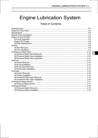
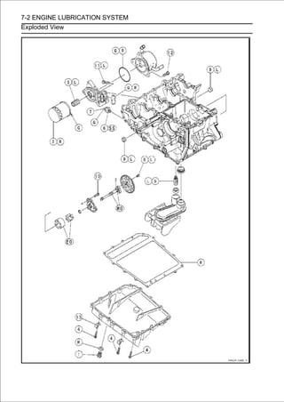
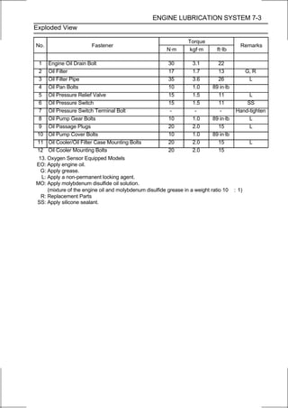
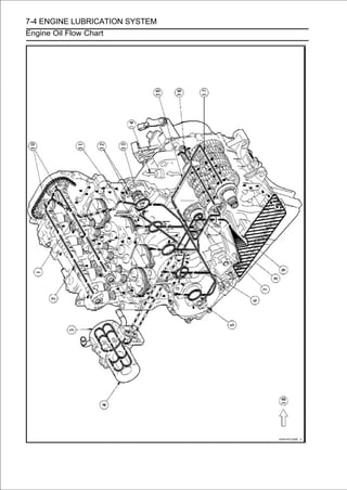
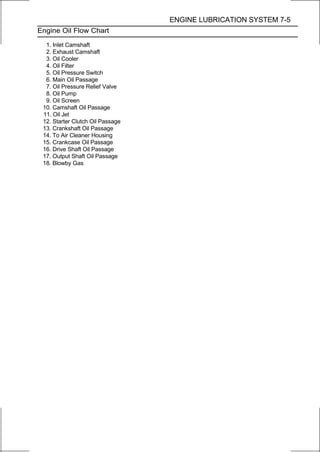
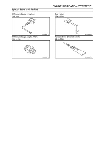
![7-8 ENGINE LUBRICATION SYSTEM
Engine Oil and Oil Filter
WARNING
Motorcycle operation with insufficient,
deteriorated, or contaminated engine oil will
cause accelerated wear and may result in engine or
transmission seizure, accident, and injury.
Oil Level Inspection
• Check that the engine oil level is between the upper [A]
and lower [B] levels in the gauge.
NOTE
○Situate the motorcycle so that it is perpendicular to the
ground.
○If the motorcycle has just been used, wait several minutes
for all the oil to drain down.
○If the oil has just been changed, start the engine and
run it for several minutes at idle speed. This fills the oil
filter with oil. Stop the engine, then wait several minutes
until the oil settles.
CAUTION
Racing the engine before the oil reaches every part
can cause engine seizure.
If the engine oil gets extremely low or if the oil pump
or oil passages clog up or otherwise do not function
properly, the warning indicator light and oil pres-
sure warning symbol will blink. If this blink stays on
when the engine is running above idle speed, stop
the engine immediately and find the cause.
If the oil level is too high, remove the excess oil, using a
syring or some other suitable device.
If the oil level is too low, add the correct amount of oil
through the oil filler opening. Use the same type and
make of oil that is already in the engine.
NOTE
○If the engine oil type and make are unknown, use any
brand of the specified oil to top off the level in preference
to running the engine with the oil level low. Then at your
earliest convenience, change the oil completely.
Engine Oil Change
• Refer to the Engine Oil Change in the Periodic
Maintenance chapter.
Oil Filter Replacement
• Refer to the Oil Filter Replacement in the Periodic
Maintenance chapter.](https://image.slidesharecdn.com/2008-100321201635-phpapp01/85/2008-341-320.jpg)
![ENGINE LUBRICATION SYSTEM 7-9
Oil Pan
Oil Pan Removal
•Drain the engine oil (see Engine Oil Change in the Periodic
Maintenance chapter).
•Remove:
Exhaust Manifold (see Exhaust Manifold Removal in the
Engine Top End chapter)
Oil Pan Bolts [A]
Clamp [B]
Clamp [C] (Oxygen Sensor Equipped Models)
Oil Pan [D]
Oil Pan Installation
• Replace the oil pan gasket [A] with a new one.
• Install the clamps [B] as shown in the figure.
Rear View [C]
• For models equipped with oxygen sensors, install the
clamp [D] in the same way as above.
• Tighten:
Torque - Oil Pan Bolts: 10 N·m (1.0 kgf·m, 89 in·lb)](https://image.slidesharecdn.com/2008-100321201635-phpapp01/85/2008-342-320.jpg)
![7-10 ENGINE LUBRICATION SYSTEM
Oil Pressure Relief Valve
Oil Pressure Relief Valve Removal
•Remove:
Oil Pan (see Oil Pan Removal)
Oil Screen [A]
• Remove the oil pressure relief valve [A].
Oil Pressure Relief Valve Installation
• Apply a non-permanent locking agent to the threads of
the oil pressure relief valve [A], and tighten it.
CAUTION
Do not apply too much non-permanent locking
agent to the threads. This may block the oil pas-
sage.
Torque - Oil Pressure Relief Valve: 15 N·m (1.5 kgf·m, 11
ft·lb)
• Cleanany particles stuck to them.high-flash point solvent and
remove
the oil screen [B] with a
○Blow away the particles by applying compressed air [C]
from the inside to the outside (from the clean side to the
dirty side).
WARNING
Clean the screen in a well-ventilated area, and take
care that there is no spark or flame anywhere near
the working area. Because of the danger of highly
flammable liquids, do not use gasoline or low-flash
point solvent.
NOTE
○While cleaning the oil screen, check for any metal
particles that might indicate internal engine damage.
• Check the screen carefully for any damage, holes, broken
wires.
If the screen is damaged, replace it.
• Install the O-ring [D] and damper [E] to the oil screen.
• Install the oil screen. so that the crankcase rib [F] and relief
valve fits
the oil screen
• Install the oil pan (see Oil Pan Installation).](https://image.slidesharecdn.com/2008-100321201635-phpapp01/85/2008-343-320.jpg)
![ENGINE LUBRICATION SYSTEM 7-11
Oil Pressure Relief Valve
Oil Pressure Relief Valve Inspection
• Remove the oil pressure relief valve (see Oil Pressure
Relief Valve Removal).
• Check to see if the valve [A] slides smoothly when push-
ing it in with a wooden or other soft rod, and see if it comes
back to its seat by spring [B] pressure.
NOTE
○Inspect the valve in its assembled state. Disassembly
and assembly may change the valve performance.
If any rough spots are found during above inspection,
wash the valve clean with a high-flash point solvent and
blow out any foreign particles that may be in the valve with
compressed air.
WARNING
Clean the oil pressure relief valve in a well
-ventilated area, and take care that there is no
spark or flame anywhere near the working area.
Because of the danger of highly flammable liquids,
do not use gasoline or low-flash point solvent.
If cleaning does not solve the problem, replace the oil
pressure relief valve as an assembly. The oil pressure
relief valve is precision made with no allowance for
replacement of individual parts.](https://image.slidesharecdn.com/2008-100321201635-phpapp01/85/2008-344-320.jpg)
![7-12 ENGINE LUBRICATION SYSTEM
Oil Pump
Oil Pump Removal
•Remove:
Oil Pump Gear (see Oil Pump Gear Removal)
Oil Pump Cover Bolts [A]
• Remove the oil pump cover [A] with oil pump gear shaft
[B].
○Stuff the cloth [C] on the hole of the crankcase so that the pin
[D] dose not drop into the crankcase bottom.
• Remove the outer rotor [E] and inner rotor [F].
Oil Pump Installation
• Apply molybdenum disulfide oil solution to the journal por-
tions [A] on the oil pump gear shaft [B] and crankcase [C].
• Install the following to the oil pump gear shaft [A].
Oil Pump Cover [B]
Washer [C]
• Install the pin [A].
• Fit the pin into the slot [B] of the inner rotor [C].
○Apply engine oil to the inner rotor.](https://image.slidesharecdn.com/2008-100321201635-phpapp01/85/2008-345-320.jpg)
![ENGINE LUBRICATION SYSTEM 7-13
Oil Pump
• Install engine oilrotor [A] on the inner rotor.
○Apply
the outer
to the outer rotor.
• Install the dowel pin [B].
• Fit the pin of the oil pump cover into the hole [C] in the
crankcase.
○Turn the oil pump gear shaft [A] so that the projection [B] in
its shaft fits onto the slot [C] of the impeller shaft.
• Tighten the oil pump cover bolts.
Torque - Oil Pump Cover Bolts: 10 N·m (1.0 kgf·m, 89 in·lb)
• Install the oil pump gear (see Oil Pump Gear Installation). Oil
Pump Gear Removal
• Remove the clutch (see Clutch Removal in the Clutch
chapter).
• Hold the oil pump gear [A] steady with the gear holder [B],
and remove the oil pump gear bolts [C].
Special Tool - Gear Holder: 57001-1599
• Remove the oil pump gear.
Oil Pump Gear Installation
• Install the oil pump gear [A] so that the stepped side [B]
faces outward.](https://image.slidesharecdn.com/2008-100321201635-phpapp01/85/2008-346-320.jpg)
![7-14 ENGINE LUBRICATION SYSTEM
Oil Pump
• Apply a non-permanent locking agent to the threads of
the oil pump gear bolts [A].
• Hold the the pump gear [B]bolts. with the gear holder [C],
and tighten
oil
oil pump gear
steady
Special Tool - Gear Holder: 57001-1599
Torque - Oil Pump Gear Bolts: 10 N·m (1.0 kgf·m, 89 in·lb)
• Install the clutch (see Clutch Installation in the Clutch
chapter).](https://image.slidesharecdn.com/2008-100321201635-phpapp01/85/2008-347-320.jpg)
![ENGINE LUBRICATION SYSTEM 7-15
Oil Cooler
Oil Cooler Removal
•Drain:
Coolant (see Coolant Change in the Periodic Mainte-
nance chapter)
Engine Oil (see Engine Oil Change in the Periodic
Maintenance chapter)
•Remove:
Right Lower Fairing (see Lower Fairing Removal in the
Frame chapter)
Water Hoses [A]
Oil Cooler Mounting Bolts [B]
Oil Cooler [C]
Oil Cooler Installation
•Replace the O-ring [A] with a new one.
•Apply grease to the new O-ring.
• Install the oil cooler [A].
• Tighten:
Torque - Oil Cooler Mounting Bolts: 20 N·m (2.0 kgf·m, 15
ft·lb)
• Install the water hoses [B] and hose clamps [C] as shown in
the figure.
Front View [D]
• Tighten:
Torque - Water Hose Clamp Screw: 2.0 N·m (0.20 kgf·m, 18
in·lb)
• Pour:
Engine Oil (see Oil Change in the Periodic Maintenance
chapter)
Coolant (see Coolant Change in the Periodic
Maintenance chapter)](https://image.slidesharecdn.com/2008-100321201635-phpapp01/85/2008-348-320.jpg)
![7-16 ENGINE LUBRICATION SYSTEM
Oil Cooler
Oil Cooler/Oil Filter Case Removal
•Remove:
Oil Filter (see Oil Filter Replacement in the Periodic
Maintenance chapter)
Oil Cooler (see Oil Cooler Removal)
Bolts [A]
Oil Cooler/Oil Filter Case [B]
○Remove the oil filter pipe [C] as necessary.
Oil Cooler/Oil Filter Case Installation
• Replace the O-ring [A] with a new one.
• Apply grease to the new O-ring.
If the oil filter pipe [B] was removed, install it as follows.
○Apply a non-permanent locking agent to the threads of
the oil filter pipe, and tighten it.
Torque - Oil Filter Pipe: 35 N·m (3.6 kgf·m, 26 ft·lb)
• Apply non-permanent locking agent totighten it. of the oil
cooler/oil filter case mounting bolts, and
the threads
Torque - Oil Cooler/Oil Filter Case Mounting Bolts: 20 N·m
(2.0 kgf·m, 15 ft·lb)
• Install:
Oil Cooler (see Oil Cooler Installation)
Oil Filter (see Oil Filter Replacement in the Periodic
Maintenance chapter)](https://image.slidesharecdn.com/2008-100321201635-phpapp01/85/2008-349-320.jpg)
![ENGINE LUBRICATION SYSTEM 7-17
Oil Pressure Measurement
Oil Pressure Measurement
•Remove:
Left Lower Fairing (see Lower Fairing Removal in the
Frame chapter)
Oil Passage Plug [A]
• Attach the adapter [A] and gauge [B] to the plug hole.
Special Tools - Oil Pressure Gauge, 10 kgf/cm²: 57001-164
Oil Pressure Gauge Adapter, PT3/8: 57001
-1233
• Start the engine and warm up the engine.
• Run the engine at the specified speed, and read the oil
pressure gauge.
Oil Pressure
Standard: 150 ∼ 230 kPa (1.5 ∼ 2.4 kgf/cm², 22 ∼ 33
psi) at 4 000 r/min (rpm), oil temperature
90°C (194°F)
If the reading is much lower than the standard, check the
oil pump, relief valve, and/or crankshaft bearing insert wear
immediately.
If the reading is much higher than the standard, check the oil
passages for clogging.
• Stop the engine.
• Remove the oil pressure gauge and adapter.
WARNING
Take care against burns form hot engine oil that
will drain through the oil passage when the gauge
adapter is removed.
• Apply ainstall it.
plug, and
non-permanent locking agent to the oil passage
Torque - Oil Passage Plugs: 20 N·m (2.0 kgf·m, 15 ft·lb)](https://image.slidesharecdn.com/2008-100321201635-phpapp01/85/2008-350-320.jpg)
![7-18 ENGINE LUBRICATION SYSTEM
Oil Pressure Switch
Oil Pressure Switch Removal
• Drain the engine oil (see Engine Oil Change in the Periodic
Maintenance chapter).
• Remove the left lower fairing (see Lower Fairing Removal in
the Frame chapter).
• Slide out the rubber boot [A].
• Loosen the oil pressure switch terminal bolt [B], and
remove the switch lead [C].
• Remove the oil pressure switch [D].
Oil Pressure Switch Installation
• Apply silicone sealant to the threads of the oil pressure
switch [A] and tighten it.
Sealant - Kawasaki Bond (Silicone Sealant): 92104-0004
Torque - Oil Pressure Switch: 15 N·m (1.5 kgf·m, 11 ft·lb)
• Apply grease to the switch terminal [B].
NOTE
○Apply a small amount grease to the terminal so that
grease should not close two breather holes [C] for
switch diaphragm.
• InstallSide switch[B] [A] direction downward.
Left
the
View
lead
• Tighten:
Torque - Oil Pressure Switch Terminal Bolt: Hand-tighten
• Slide back the rubber boot to the original position.](https://image.slidesharecdn.com/2008-100321201635-phpapp01/85/2008-351-320.jpg)
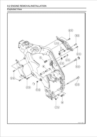
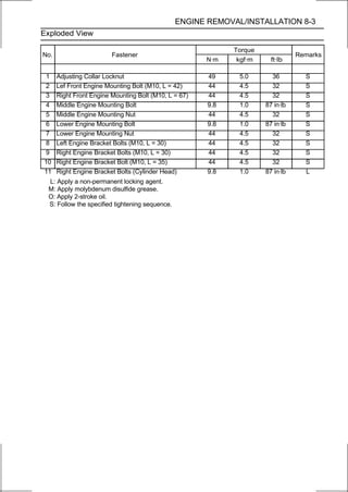
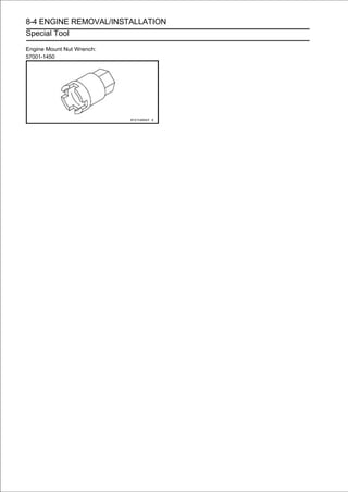
![ENGINE REMOVAL/INSTALLATION 8-5
Engine Removal/Installation
Engine Removal
• Support the rear part of the swingarm with a stand.
• Squeeze the brake lever slowly and hold it with a band
[A].
WARNING
Be sure to hold the front brake when removing the
engine, or the motorcycle may fall over. It could
cause an accident and injury.
CAUTION
Be sure to hold the front brake when removing the
engine, or the motorcycle may fall over. The engine or
the motorcycle could be damaged.
• Drain:
Engine Oil (see Engine Oil Change in the Periodic
Maintenance chapter)
Coolant (see Coolant Change in the Periodic Mainte-
nance chapter)
• Remove:
Upper Fairing Assembly (see Upper Fairing Assembly
Removal in the Frame chapter)
Coolant Reserve Tank (see Coolant Reserve Tank
Removal in the Cooling System chapter)
Fuel Tank (see Fuel Tank Removal in the Fuel System
(DFI) chapter)
Air Cleaner Housing (see Air Cleaner Housing Removal in
the Fuel System (DFI) chapter)
Throttle Body Assy (see Throttle Body Assy Removal in
the Fuel System (DFI) chapter)
Clutch Cable Lower End (see Cable Removal in the
Clutch chapter)
Radiator (see Radiator and Radiator Fan Removal in the
Cooling System chapter)
Exhaust Manifold (see Exhaust Manifold Removal in the
Engine Top End chapter)
Shift Lever (see Shift Pedal Removal in the
Crankshaft/Transmission chapter)
Engine Sprocket (see Engine Sprocket Removal in the
Final Drive chapter)
Drain the coolant from the cylinder (upper crankcase) be-
forehand if the engine is to be disassembled.
○Place a container under the drain bolt [A] and remove it.
• Tighten the drain bolt with gasket.
Replace the drain bolt gasket with a new one if it is dam-
aged.
Torque - Coolant Drain Bolt (Cylinder): 10 N·m (1.0 kgf·m,
89 in·lb)](https://image.slidesharecdn.com/2008-100321201635-phpapp01/85/2008-356-320.jpg)
![8-6 ENGINE REMOVAL/INSTALLATION
Engine Removal/Installation
• Pull off the connectors from the engine and free the wiring
from the clamps.
• Disconnect:
Stick Coil Connectors [A]
Air Switching Valve Connector [B]
• Disconnect the sidestand switch lead connector [A].
• Disconnect:
Regulator/Rectifier Connector (Gray) [A]
• Disconnect the crankshaft sensor lead connector [A].
• Disconnect the engine subharness #1 connector [A].
• Remove the engine ground cable terminal bolt [B].](https://image.slidesharecdn.com/2008-100321201635-phpapp01/85/2008-357-320.jpg)
![ENGINE REMOVAL/INSTALLATION 8-7
Engine Removal/Installation
• Remove the starter motor cable [A].
• Support the engine with a suitable stand [A].
○Put a plank [B] onto the suitable stand for engine balance.
• Remove:
Left Upper Inner Fairing Bracket Bolts [A]
Left Upper Inner Fairing Bracket [B]
• Remove:
Left Engine Bracket Bolts [A]
Left Engine Bracket [B]
• Remove:
Right Upper Inner Fairing Bracket Bolts [A]
Right Upper Inner Fairing Bracket [B]](https://image.slidesharecdn.com/2008-100321201635-phpapp01/85/2008-358-320.jpg)
![8-8 ENGINE REMOVAL/INSTALLATION
Engine Removal/Installation
• Remove:
Right Engine Bracket Bolts [A]
Right Engine Bracket [B]
• Remove:
Left Front Engine Mounting Bolt [A]
Plug (Both Sides)
Middle Engine Mounting Nut [B]
Lower Engine Mounting Nut [C]
• Turn thetomiddle the gap between the adjusting collarbolts
clockwise make
[A] and lower [B] engine mounting
and frame.
• Pull out the engine mounting bolts from the right side.
○Remove the collar while pulling out the middle engine
mounting bolt.
•Remove the right front engine mounting bolts [C].
• Using the nut wrench [A], loosen the locknut [B].
Special Tool - Engine Mount Nut Wrench: 57001-1450
• Using the Hexagon Wrench, turn the adjusting collar [A]
counterclockwise to make the gap between the engine
and adjusting collar.](https://image.slidesharecdn.com/2008-100321201635-phpapp01/85/2008-359-320.jpg)
![ENGINE REMOVAL/INSTALLATION 8-9
Engine Removal/Installation
• Remove the drive chain [A] from the output shaft [B].
• Using the stand, take out the engine.
Engine Installation
•Support the engine with a suitable stand.
○Put a plank onto the suitable stand for engine balance.](https://image.slidesharecdn.com/2008-100321201635-phpapp01/85/2008-360-320.jpg)
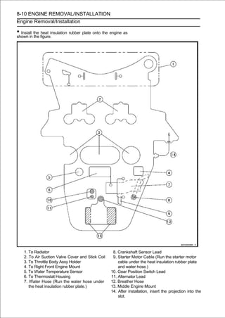
![ENGINE REMOVAL/INSTALLATION 8-11
Engine Removal/Installation
• Install the engine mounting bolts and nuts, following the
specified installing sequence.
○Apply molybdenum disulfide grease to the threads of the
adjusting collars [A].
○Apply 2-stroke oil to the threads of the adjusting collar [B].
○First, install the adjusting collars [A] [B] to the crankcase
and frame.
Crankcase [C]
Frame [D]](https://image.slidesharecdn.com/2008-100321201635-phpapp01/85/2008-362-320.jpg)
![8-12 ENGINE REMOVAL/INSTALLATION
Engine Removal/Installation
○Second, hang the drive chain over the output shaft just
before mounting the engine into its final position in the
frame.
○Third, install the bolts [A] [B] [C] [D] temporarily, and
tighten the bolt [C].
Torque - Left Front Engine Mounting Bolt: 44 N·m (4.5
kgf·m, 32 ft·lb)
○When installing the middle engine mounting bolt [B], in-
stall the collar [E] between frame and crankcase.
○Forth, Insert the lower [A] and middle [B] engine mount-
ing bolts to the adjusting collars [F], and tighten the bolts
counterclockwise.
NOTE
○Tighten the bolts until the clearance [G] between the
frame and collar come to 0 mm (0 in.).
Torque - Middle Engine Mounting Bolt: 9.8 N·m (1.0 kgf·m,
87 in·lb)
Lower Engine Mounting Bolt: 9.8 N·m (1.0 kgf·m,
87 in·lb)
○Fifth, tighten the middle engine mounting nut [H], and then
lower engine mounting nut [I].
Torque - Middle Engine Mounting Nut: 44 N·m (4.5 kgf·m,
32 ft·lb)
Lower Engine Mounting Nut: 44 N·m (4.5 kgf·m,
32 ft·lb)
○After tightening the middle engine mounting nut, install
the plug [J] on both sides.
○Sixth, remove the bolt [D] temporarily, and using the
hexagon wrench, turn the adjusting collar [K] until the
clearance [L] between the cylinder head and collar come
to 0 mm (0 in.).
○Seventh, using the engine mount nut wrench (special
tool), tighten the adjusting collar locknut [M].
Special Tool - Engine Mount Nut Wrench: 57001-1450
Torque - Adjusting Collar Locknut: 49 N·m (5.0 kgf·m, 36
ft·lb)
○Lastly, reinstall the bolt [D] and tighten it.
Torque - Right Front Engine Mounting Bolt: 44 N·m (4.5
kgf·m, 32 ft·lb)](https://image.slidesharecdn.com/2008-100321201635-phpapp01/85/2008-363-320.jpg)
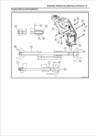
![8-14 ENGINE REMOVAL/INSTALLATION
Engine Removal/Installation
• Install the installingand right [B] engine bracket, following
the specified
left [A]
sequence.
○First, install the adjusting collar [C] to the right engine
bracket [B].
○Second, install the bolts [D] [E] [F] [G] temporarily as
shown sequence [1 ∼ 8] in the figure.
○Third, tighten the bolts [D] as shown sequence [1 ∼ 3] in the
figure.
Torque - Left Engine Bracket Bolts: 44 N·m (4.5 kgf·m, 32
ft·lb)
○Forth, tighten the bolts [E] as shown sequence [5 ∼ 7] in the
figure.
Torque - Right Engine Bracket Bolts (M10, L = 30): 44 N·m
(4.5 kgf·m, 32 ft·lb)
○Fifth, tighten the bolt [F].
Torque - Left Engine Bracket Bolt: 44 N·m (4.5 kgf·m, 32
ft·lb)
○Sixth, remove the bolt [G] temporarily, and using the
hexagon wrench, turn the adjusting collar [C] until the
clearance [H] between the right engine bracket (cylinder
head) [I] and collar come to 0 mm (0 in.).
○Lastly, reinstall the bolt [G], and tighten it.
Torque - Right Engine Bracket Bolt (M10, L = 35): 44 N·m
(4.5 kgf·m, 32 ft·lb)
• Install the left and right upper inner fairing brackets.
• Run theRouting sectionandthe Appendix chapter). Cable, Wire
and Hose
leads, cable
in
hoses correctly (see
• Tighten:
Torque - Engine Ground Cable Terminal Bolt: 10 N·m (1.0
kgf·m, 89 in·lb)
• Install the removed parts (see appropriate chapters).
• Adjust:
Throttle Cables (see Throttle Control System Inspection
in the Periodic Maintenance chapter)
Clutch Cable (see Clutch Operation Inspection in the
Periodic Maintenance chapter)
Drive Chain (see Drive Chain Slack Adjustment in the
Periodic Maintenance chapter)
• Fill the engine with engine oil (see Engine Oil Change in
the Periodic Maintenance chapter).
• Fill the engine with coolant and bleed the air from the cool-
ing system (see Coolant Change in the Periodic Mainte-
nance chapter).](https://image.slidesharecdn.com/2008-100321201635-phpapp01/85/2008-365-320.jpg)
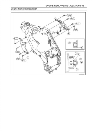

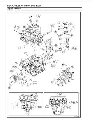
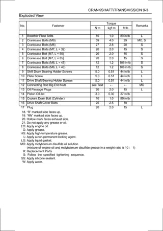
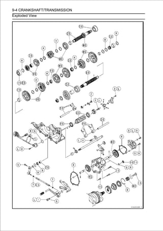
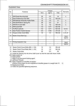
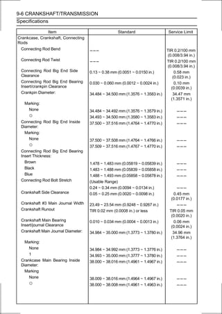
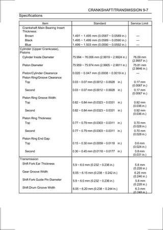
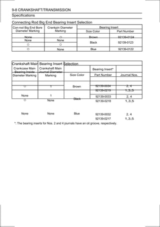
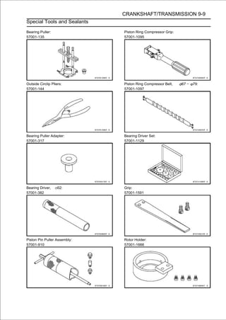
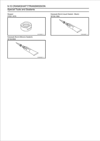
![CRANKSHAFT/TRANSMISSION 9-11
Crankcase
Crankcase Splitting
• Remove the engine (see Engine Removal in the Engine
Removal/Installation chapter).
• Set the engine on a clean surface and hold the engine
steady while parts are being removed.
• Remove:
Crankshaft Sensor (see Crankshaft Sensor Removal in
the Electrical System chapter)
Starter Clutch (see Starter Clutch Removal)
Cylinder Head (see Cylinder Head Removal in the Engine
Top End chapter)
Starter Motor (see Starter Motor Removal in the Electrical
System chapter)
Clutch (see Clutch Removal in the Clutch chapter)
Oil Pump (see Oil Pump Removal in the Engine
Lubrication System chapter)
Alternator Rotor (see Alternator Rotor Removal in the
Electrical System chapter)
Oil Cooler/Oil Filter Case (see Oil Cooler/Oil Filter Case
Removal in the Engine Lubrication System chapter)
Oil Pan (see Oil Pan Removal in the Engine Lubrication
System chapter)
Oil Screen (see Oil Pressure Relief Valve Removal in the
Engine Lubrication System chapter)
External Shift Mechanism (see External Shift
Mechanism Removal)
• fied sequence. crankcase bolts, following the speci-
Remove the upper
○Firstly, loosen the M6 bolts [A].
○Secondly, loosen the M7 bolts [B].
○Lastly, loosen the M8 bolts [C].](https://image.slidesharecdn.com/2008-100321201635-phpapp01/85/2008-378-320.jpg)
![9-12 CRANKSHAFT/TRANSMISSION
Crankcase
• Remove the lower crankcase bolts, following the specified
sequence.
○First, loosen the M6 bolts [A].
○Second, loosen the M7 bolts [B].
○Lastly, loosen the M9 bolts as shown sequence [1 ∼ 10] in
the figure.
• Tap lightly around the crankcase mating surface with a
plastic mallet, and split the crankcase.
○Take care not to damage the crankcase.
Crankcase Assembly
CAUTION
The upper and lower crankcase halves are ma-
chined at the factory in the assembled state, so the
crankcase halves must be replaced as a set.
• With a high-flash point solvent, wipe dry.
surfaces of the crankcase halves and
clean off the mating
WARNING
Clean the crankcase in a well-ventilated area, and
take care that there is no spark or flame anywhere
near the working area. Because of the danger of
highly flammable liquids, do not use gasoline or low
-flash point solvent.
• Using compressed air, blow out the oil passage in the
crankcase halves.](https://image.slidesharecdn.com/2008-100321201635-phpapp01/85/2008-379-320.jpg)
![CRANKSHAFT/TRANSMISSION 9-13
Crankcase
• Apply liquid gasket more thick, and then install thesurface
[A] 1 mm (0.04 in.) or
to the breather plate mating
breather plate.
Sealant - Three Bond: TB1207B
NOTE
○Make the application finish within 7 minutes when the
liquid gasket to the mating surface of the breather plate
is applied.
○Moreover fit the plate and tighten the bolts just after
application of the liquid gasket.
• Apply plate bolts [A] and locking them. to the treads of the
breather
a non-permanent
tighten
agent
Torque - Breather Plate Bolts: 10 N·m (1.0 kgf·m, 89 in·lb)
• Install the following parts on the upper crankcase half.
Output Shaft [A] (see Transmission Shaft Installation)
Crankshaft [B] (see Crankshaft Installation)
Pistons and Connecting Rods [C] (see Connecting Rod
Installation)
Camshaft Chain [D]
Dowel Pins [E]
• Install Shaft [A] (seeparts on the lower crankcase half.
Drive
the following
Transmission Installation)
Shift Drum [B] (see Shift Drum and Fork Installation)
Shift Forks [C] and Shift Rods (see Shift Drum and Fork
Installation)
• Before items. the lower case on the upper case, check the
following
fitting
○Check to see that the shift drum cam [A] and transmission
gears are in the neutral position [B].
○Be sure to hang the camshaft chain on the crankshaft.](https://image.slidesharecdn.com/2008-100321201635-phpapp01/85/2008-380-320.jpg)
![9-14 CRANKSHAFT/TRANSMISSION
Crankcase
• Apply liquid gasket [A] to the mating surface of the lower
crankcase half.
Sealant - Kawasaki Bond (Liquid Gasket - Black): 92104
-1064
NOTE
○Especially, apply a sealant so that it shall be filled up on the
grooves [B].
○Do not apply liquid gasket to the inside of the grooves
[C].
CAUTION
Do not apply liquid gasket around the crankshaft
main bearing inserts, and oil passage hole.
• Fit the lower crankcase half to the upper crankcase half.
NOTE
○Make the application finish within 20 minutes when the
liquid gasket to the mating surface of the crankcase half
is applied.
○Moreover fit the case and tighten the bolts just after
application of the liquid gasket.](https://image.slidesharecdn.com/2008-100321201635-phpapp01/85/2008-381-320.jpg)
![CRANKSHAFT/TRANSMISSION 9-15
Crankcase
• The new bolts [A] has a copper plated washer [B], replace it
with a
M9
one.
• Apply molybdenum disulfide oil solution to both sides [C] of
the washers and threads [D] of M9 bolts.
• Tighten the lower crankcase bolts using the following
steps.
○Following the sequence numbers on the lower crankcase
half, M9 bolts [1 ∼ 10] with copper plated washers.
Torque - Crankcase Bolts (M9): 39 N·m (4.0 kgf·m, 29 ft·lb)
○Tighten the M7 bolts.
Torque - Crankcase Bolts (M7): 20 N·m (2.0 kgf·m, 15 ft·lb)
L=50mm(1.97in.) [A]
L=85mm(3.35in.) [B]
○Install the clamp [C], and tighten the M6 bolts [D].
Torque - Crankcase Bolts (M6): 12 N·m (1.2 kgf·m, 106 in·lb)](https://image.slidesharecdn.com/2008-100321201635-phpapp01/85/2008-382-320.jpg)
![9-16 CRANKSHAFT/TRANSMISSION
Crankcase
• Tighten the upper crankcase bolts using the following
steps.
○The M8 bolts [A] has a washer, replace it with a new one.
○Tighten the M8 bolts with washers.
Torque - Crankcase Bolts (M8): 27 N·m (2.8 kgf·m, 20 ft·lb)
○Tighten the M7 bolts [B].
Torque - Crankcase Bolts (M7): 20 N·m (2.0 kgf·m, 15 ft·lb)
○Tighten the M6 bolts [C].
Torque - Crankcase Bolts (M6): 12 N·m (1.2 kgf·m, 106 in·lb)
• After tightening all crankcase bolts, check the following
items.
○Wipe up the liquid gasket that seeps out around the
crankcase mating surface.
○Crankshaft and transmission shaft turn freely.
○Wile spinng the output shaft, gears shift smoothly from
the 1st to 6th gear, and 6th to 1st.
○When the output shaft stays still, the gear can not be
shifted to 2nd gear or other higher gear positions.
• Install the removed parts (see appropriate chapters).](https://image.slidesharecdn.com/2008-100321201635-phpapp01/85/2008-383-320.jpg)
![CRANKSHAFT/TRANSMISSION 9-17
Crankshaft and Connecting Rods
Crankshaft Removal
•Split the crankcase (see Crankcase Splitting).
•Remove:
Camshaft Chain (Camshaft Chain Removal in the En-
gine Top End chapter)
Connecting Rod Big End Caps (see Connecting Rod Re-
moval)
Crankshaft [A]
• Removecrankcase half as follows. the #3 main journal of
the upper
the thrust washers [A] from
○Slide [B] the thrust washers upward and remove them.
Crankshaft Installation
NOTE
○If the crankshaft is replaced with a new one, refer to
the Connecting Rod Big End Bearing/Crankshaft Main
Bearing Insert Selection in the Specifications.
CAUTION
If the crankshaft, bearing inserts, or crankcase
halves are replaced with new ones, select the bear-
ing inserts and check clearance with a plastigage
(press gauge) before assembling engine to be sure
the correct bearing inserts are installed.
• Apply molybdenum disulfide oil solution to the crankshaft
main bearing inserts.
• Install the crankshaft [A] with the camshaft chain [B] hanging
on it.
• Install the connecting rod big end caps (see Connecting
Rod Installation).](https://image.slidesharecdn.com/2008-100321201635-phpapp01/85/2008-384-320.jpg)
![9-18 CRANKSHAFT/TRANSMISSION
Crankshaft and Connecting Rods
NOTE
○The thrust washer [A] has oil grooves [B] on the one
side.
○The thrust washers are identical.
• Applyof the thrust washers. grease [C] to the oil groove
side [D]
molybdenum disulfide
• Slide [E] thejournal so that the oil grooves face outward.
of the #3 main
thrust washer of the one side into the groove
• Move the crankshaft toside into or right, and then#3 the
thrust washer of the other
the left
the groove of the
slide
main journal in the same way.
• After installation, confirm that the blue-painted edges [F]
of the thrust washers are positioned as shown in the fig-
ure.
Front [G]
Connecting Rod Removal
•Split the crankcase (see Crankcase Splitting).
•Remove the connecting rod nuts [A] and big end caps [B].
NOTE
○Mark and record the locations of the connecting rods
and their big end caps so that they can be reassembled in
their original positions.](https://image.slidesharecdn.com/2008-100321201635-phpapp01/85/2008-385-320.jpg)
![CRANKSHAFT/TRANSMISSION 9-19
Crankshaft and Connecting Rods
• Remove:
Camshaft Chain (see Camshaft Chain Removal in the
engine Top End chapter)
Crankshaft [A]
Pistons (see Piston Removal)
CAUTION
Discard the connecting rod bolts and nuts. To pre-
vent damage to the crankpin surfaces, do not al-
low the connecting rod bolts to bump against the
crankpins.
Connecting Rod Installation
CAUTION
To minimize vibration, the connecting rods should
have the same weight mark.
Big End Cap [A]
Connecting Rod [B]
Weight Mark, Alphabet [C]
Diameter Mark [D]: “○” or no mark
CAUTION
If the connecting rods, big end bearing inserts, or
crankshaft are replaced with new ones, select the
bearing insert and check clearance with a plasti-
gage (press gauge) before assembling engine to be
sure the correct bearing inserts are installed.
• face ofmolybdenum disulfidebearing inserts the inner sur-
Apply
the upper and lower
oil solution to
[A].
• and seating surface [C] of the connecting rod nuts.
Apply molybdenum disulfide oil solution to the threads [B]
• Install the inserts so that their nails [D] are on the same
side and fit them into the recess of the connecting rod and
cap.
CAUTION
Wrong application of oil and grease could cause
bearing damage.
○When installing the inserts [A], be careful not to damage
the insert surface with the edge of the connecting rod [B]
or the cap [C]. One way to install inserts is as follows.
Installation [D] to Cap
Installation [E] to Connecting Rod
Push [F]
Spare Dowel Pin [G]
Connecting Rod Bolts [H]
• Remove debris and clean the surface of inserts.
• Install the cap on the connecting rod, aligning the weight
and diameter marks.](https://image.slidesharecdn.com/2008-100321201635-phpapp01/85/2008-386-320.jpg)
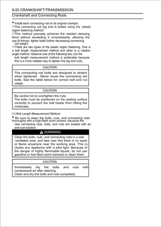
![CRANKSHAFT/TRANSMISSION 9-21
Crankshaft and Connecting Rods
• Install new bolts and nuts in reused connecting rod.
If the connecting rod assy was replaced, use the bolts and
nuts attached to the new connecting rod assy.
• Apply a small amount of molybdenum disulfide oil solution to
the following portions.
Threads [A] of Nuts and Bolts
Seating Surfaces [B] of Nuts and Connecting Rods
• Dent both bolt head and bolt tip with a punch as shown in the
figure.
• Beforenew connecting rodpoint micrometer themeasure the
length of
tightening, use a
bolts and record
to
values
to find the bolt stretch.
Connecting Rod [A]
Dent here with a punch [B].
Nuts [C]
Fit micrometer pins into dents [D].
• Tighten the big end nuts until the bolt elongation reaches
the length specified as follows.
Bolt Length after
tightening - Bolt Length before = Bolt Stretch
tightening
Connecting Rod Bolt Stretch
Usable Range: 0.24 ∼ 0.34 mm (0.0094 ∼ 0.0134 in.)
• Check the length of the connecting rod bolts.
If the stretch is more than the usable range, the bolt has
stretched too much. An overelongated bolt may break in
use.
(2) Rotation Angle Method
If you do not have a point micrometer, you may tighten
the nuts using the “Rotation Angle Method”.
• Be sure to clean the bolts, nuts and connecting rods thor-
oughly with a high-flash point solvent, because the new
connecting rods, bolts and nuts are treated with an anti
-rust solution.
WARNING
Clean the bolts, nuts and connecting rods in a well
-ventilated area, and take care that there is no spark
or flame anywhere near the working area. This in-
cludes any appliance with a pilot light. Because of
the danger or highly flammable liquids, do not use
gasoline or low-flash point solvents to clean them.
CAUTION
Immediately dry the bolts and nuts with
compressed air after cleaning.
Clean and dry the bolts and nuts completely.](https://image.slidesharecdn.com/2008-100321201635-phpapp01/85/2008-388-320.jpg)
![9-22 CRANKSHAFT/TRANSMISSION
Crankshaft and Connecting Rods
• Install new bolts and nuts in reused connecting rods.
If the connecting rod assy was replaced, use the bolts and
nuts attached to the new connecting rod assy.
• Apply a small amount of molybdenum disulfide oil solution to
the following portions.
Threads [A] of Nuts and Bolts
Seating Surfaces [B] of Nuts and Connecting Rods
• First, tighten the nuts with 20 N·m (2.0 kgf·m, 15 ft·lb) of
torque.
• Next, tighten the nuts 150°.
○Mark [A] the connecting rod big end caps and nuts so that
nuts can be turned 150° [B] properly.
Connecting
Torque + Angle
Rod Assy Bolt Nut
N·m (kgf·m, ft·lb)
Attached to Attached to
New new con-rod new con-rod 20 (2.0,15) + 150°
New New
Replace the Replace the
Used bolts with nuts with new 20 (2.0,15) + 150°
new ones ones
Crankshaft/Connecting Rod Cleaning
• After removing the connecting rods from the crankshaft,
clean them with a high-flash point solvent.
• Blow the crankshaft oil passages with compressed air to
remove any foreign particles or residue that may have
accumulated in the passages.
Connecting Rod Bend
• Remove the connecting rod big end bearing inserts, and
reinstall the connecting rod big end cap.
• Select an arbor [A] of the same diameter as the connect-
ing rod big end, and insert the arbor through the connect-
ing rod big end.
• Select an arbor of the same diameter as the piston pin
and at least 100 mm (3.94 in.) long, and insert the arbor
[B] through the connecting rod small end.
• On a surface plate, set the big-end arbor on V block [C].
• With the connecting rod held vertically, use a height
gauge to measure the difference in the height of the
arbor above the surface plate over a 100 mm (3.94 in.)
length to determine the amount of connecting rod bend. If
connecting rod bend exceeds the service limit, the
connecting rod must be replaced.
Connecting Rod Bend
Service Limit: TIR 0.2/100 mm (0.008/3.94 in.)](https://image.slidesharecdn.com/2008-100321201635-phpapp01/85/2008-389-320.jpg)
![CRANKSHAFT/TRANSMISSION 9-23
Crankshaft and Connecting Rods
Connecting Rod Twist
• With the big-end arbor [A] still on V block [C], hold the
connecting rod horizontally and measure the amount that
the arbor [B] varies from being paralleled with the surface
plate over a 100 mm (3.94 in.) length of the arbor to
determine the amount of connecting rod twist.
If connecting rod twist exceeds the service limit, the
connecting rod must be replaced.
Connecting Rod Twist
Service Limit: TIR 0.2/100 mm (0.008/3.94 in.)
Connecting Rod Big End Side Clearance
•Measure connecting rod big end side clearance.
○Insert a thickness gauge [A] between the big end and ei-
ther crank web to determine clearance.
Connecting Rod Big End Side Clearance
Standard: 0.13 ∼ 0.38 mm (0.0051 ∼ 0.0150 in.)
Service Limit: 0.58 mm (0.023 in.)
If the clearance exceeds the service limit, replace the
connecting rod with new one and then check clearance again.
If clearance is too large after connecting rod replacement, the
crankshaft also must be replaced.
Connecting Rod Big End Bearing Insert/Crankpin
Wear
• Remove the connecting rod big end (see Connecting Rod
Removal).
• Cut strips of plastigage to crankpin width. Place a strip
on the crankpin parallel to the crankshaft installed in the
correct position.
• Tighten the connecting rod big end nuts to the specified
torque (see Connecting Rod Installation).
NOTE
○Do not move the connecting rod and crankshaft during
clearance measurement.
• Removebetween the bearing insert and crankpin [B] us-each
clearance
the connecting rod big end again, measure
ing plastigage (press gauge) [A].
CAUTION
After measurement, replace the connecting rod
bolts and nuts.
Connecting Rod Big End Bearing Insert/Crankpin
Clearance
Standard: 0.030 ∼ 0.060 mm (0.0012 ∼ 0.0024 in.)
Service Limit: 0.10 mm (0.0039 in.)](https://image.slidesharecdn.com/2008-100321201635-phpapp01/85/2008-390-320.jpg)
![9-24 CRANKSHAFT/TRANSMISSION
Crankshaft and Connecting Rods
If the clearance is within the standard, no bearing
replacement is required.
If the clearance is between 0.061 mm (0.0024 in.) and
the service limit (0.10 mm, 0.0039 in.), replace the bear-
ing inserts [A] with inserts painted blue [B]. Check in-
sert/crankpin clearance with the plastigage. The clear-
ance may exceed the standard slightly, but it must not be
less than the minimum in order to avoid bearing seizure.
If the clearance exceeds the service limit, measure the
diameter of the crankpins.
Crankpin Diameter
Standard: 34.484 ∼ 34.500 mm (1.3576 ∼ 1.3583 in.)
Service Limit: 34.47 mm (1.3571 in.)
If any crankpin has worn past the service limit, replace the
crankshaft with a new one.
If the measured crankpin diameters are not less than the
service limit, but do not coincide with the original diameter
markings on the crankshaft, make new marks on it.
Crankpin Diameter Marks
None 34.484 ∼ 34.492 mm (1.3576 ∼ 1.3579 in.)
○ 34.493 ∼ 34.500 mm (1.3580 ∼ 1.3583 in.)
: Crankpin Diameter Marks, “○” or no mark.
• Measureconnecting rod big end inend inside diameter, and
mark each
the connecting rod big
accordance with the
inside diameter.
• Tighten the connecting rod big end nuts to the specified
torque (see Connecting Rod Installation).
NOTE
○The mark already on the big end should almost coincide
with the measurement.
Connecting Rod Big End Inside Diameter Marks
None 37.500 ∼ 37.508 mm (1.4764 ∼ 1.4766 in.)
○ 37.509 ∼ 37.516 mm (1.4767 ∼ 1.4770 in.)
Big End Cap [A]
Connecting Rod [B]
Weight Mark, Alphabet [C]
Diameter Mark (Around Weight Mark) [D]: “○” or no
mark](https://image.slidesharecdn.com/2008-100321201635-phpapp01/85/2008-391-320.jpg)
![CRANKSHAFT/TRANSMISSION 9-25
Crankshaft and Connecting Rods
• Select theof the connectinginsertand crankshaft coding. the
combination
proper bearing
rod
[A] in accordance with
Size Color [B]
Con-rod Big
Bearing Insert
End Inside Crankpin
Diameter Diameter
Marking Size Color Part Number
Marking
None ○ Brown 92139-0124
None None
Black 92139-0123
○ ○
○ None Blue 92139-0122
• Install the new insertswiththe connecting rod and check
insert/crankpin clearance
in
the plastigage.
Crankshaft Side Clearance
• Insert a thickness gauge [A] between the thrust washer
[B] on the crankcase and the crank web [C] at the #3 main
journal to determine clearance.
If the clearance exceeds the service limit, replace the
thrust washers as a set and check the width of the
crankshaft #3 main journal.
Crankshaft Side Clearance
Standard: 0.05 ∼ 0.25 mm (0.0020 ∼ 0.0098 in.)
Service Limit: 0.45 mm (0.0177 in.)
• Measure the width [A] of the crankshaft #3 main journal
[B].
If the measurement exceeds the standard, replace the
crankshaft.
Crankshaft #3 Main Journal Width
Standard: 23.49 ∼ 23.54 mm (0.9248 ∼ 0.9267 in.)
Crankshaft Runout
•Measure the crankshaft runout.
If the measurement exceeds the service limit, replace the
crankshaft.
Crankshaft Runout
Standard: TIR 0.02 mm (0.0008 in.) or less
Service Limit: TIR 0.05 mm (0.0020 in.)](https://image.slidesharecdn.com/2008-100321201635-phpapp01/85/2008-392-320.jpg)
![9-26 CRANKSHAFT/TRANSMISSION
Crankshaft and Connecting Rods
Crankshaft Main Bearing Insert/Journal Wear
• Split the crankcase (see Crankcase Splitting).
• Cut strips of plastigage to journal width. Place a strip
on each journal parallel to the crankshaft installed in the
correct position.
• Tighten the crankcase bolts to the specified torque (see
Crankcase Assembly).
NOTE
○Do not turn the crankshaft during clearance measure-
ment.
○Journal clearance less than 0.025 mm (0.00098 in.) can not
be measured by plastigage, however, using genuine parts
maintains the minimum standard clearance.
• Splitthe bearing insertagain, measureusing plastigage be-
tween
the crankcase
and journal [B]
each clearance
(press gauge) [A].
Crankshaft Main Bearing Insert/Journal Clearance
Standard: 0.010 ∼ 0.034 mm (0.0004 ∼ 0.0013 in.)
Service Limit: 0.06 mm (0.0024 in.)
If the clearance is within the standard, no bearing
replacement is required.
If the clearance is between 0.035 mm (0.0014 in.) and the
service limit (0.06 mm, 0.0024 in.), replace the bearing
inserts [A] with inserts painted blue [B]. Check insert/journal
clearance with the plastigage. The clearance may exceed the
standard slightly, but it must not be less than the minimum in
order to avoid bearing seizure.
If the clearance exceeds the service limit, measure the
diameter of the crankshaft main journal.
Crankshaft Main Journal Diameter
Standard: 34.984 ∼ 35.000 mm (1.3773 ∼ 1.3780 in.)
Service Limit: 34.96 mm (1.3764 in.)
If any journal has worn past the service limit, replace the
crankshaft with a new one.
If the measured journal diameters are not less than the
service limit, but do not coincide with the original diameter
markings on the crankshaft, make new marks on it.
Crankshaft Main Journal Diameter Marks
None 34.984 ∼ 34.992 mm (1.3773 ∼ 1.3776 in.)
1 34.993 ∼ 35.000 mm (1.3777 ∼ 1.3780 in.)
□: Crankshaft Main Journal Diameter Marks, “1” or no
mark.](https://image.slidesharecdn.com/2008-100321201635-phpapp01/85/2008-393-320.jpg)
![CRANKSHAFT/TRANSMISSION 9-27
Crankshaft and Connecting Rods
• Measure the main in accordance with the inside diam- the
upper crankcase half
bearing inside diameter, and mark
eter.
[A]: Crankcase Main Bearing Inside Diameter Marks, “ ○”
mark or no mark.
• Tighten the crankcase bolts to the specified torque (see
Crankcase Assembly).
NOTE
○The mark already on the upper crankcase half should
almost coincide with the measurement.
Crankcase Main Bearing Inside Diameter Marks
○ 38.000 ∼ 38.008 mm (1.4961 ∼ 1.4963 in.)
None 38.009 ∼ 38.016 mm (1.4964 ∼ 1.4967 in.)
• Select the proper bearing insert [A] in accordance with the
combination of the crankcase and crankshaft coding.
Size Color [B]
Crankcase Main Crankshaft Main Bearing Insert*
Bearing Inside Journal Diameter
Diameter Marking Marking Size Color Part Number Journal Nos.
○ 1 Brown 92139-0034 2, 4
92139-0219 1,3,5
None 1 92139-0033 2, 4
Black
○ None 92139-0218 1,3,5
None None Blue 92139-0032 2, 4
92139-0217 1,3,5
*: The bearing inserts for Nos. 2 and 4 journals have an oil groove, respectively.
• Install the new inserts in the crankcase halves and check
insert/journal clearance with the plastigage.](https://image.slidesharecdn.com/2008-100321201635-phpapp01/85/2008-394-320.jpg)
![9-28 CRANKSHAFT/TRANSMISSION
Pistons
Piston Removal
• Split the crankcase (see Crankcase Splitting).
• Remove the connecting rod nuts [A] and big end caps [B].
NOTE
○Mark and record the locations of the connecting rods
and their big end caps so that they can be reassembled in
their original positions.
• Remove:
Camshaft Chain (see Camshaft Chain Removal in the
engine Top End chapter)
Crankshaft [A]
• Remove the connecting rods with pistons to the cylinder
head side [B].
• Remove the piston pin snap rings [A].
• Using the piston pin puller assembly [A], remove the piston
pins.
Special Tool - Piston Pin Puller Assembly: 57001-910
• Remove the pistons from the connecting rods.
• Carefully spread opposite side of thewith [A] to remove and
then push up on the
the ring opening
ring
your thumbs
it.
• Remove the 3-piece oil ring with your thumbs in the same
manner.](https://image.slidesharecdn.com/2008-100321201635-phpapp01/85/2008-395-320.jpg)
![CRANKSHAFT/TRANSMISSION 9-29
Pistons
Piston Installation
• Apply molybdenum disulfide oil solution to the oil ring ex-
pander, and install the oil ring expander [A] in the bottom
piston ring groove so the ends [B] butt together.
• Apply molybdenum disulfide oil solution to the oil ring steel
rails, and install the oil ring steel rails, one above the ex-
pander and one below it.
○Spread the rail with your thumbs, but only enough to fit
the rail over the piston.
○Release the rail into the bottom piston ring groove.
NOTE
○The oil ring rails have no “top” or “bottom”.
• Apply molybdenum disulfide oil solution to the piston
rings.
NOTE
○Do not mix up the top and second ring.
• Install the top ring [A] so that the “R” mark [B] faces up.
• Install the second ring [C] so that the “RN” mark [D] faces
up.
• Apply molybdenum disulfide oil solution to the piston pins
and piston journals.
NOTE
○If a new piston is used, use new piston ring.
• Fit a the ring opening snap ringnot coincide with the slit
so that
new piston pin
[A] does
into the side of the piston
[B] of the piston pin hole.
○When installing the piston pin snap ring, compress it only
enough to install it and no more.
CAUTION
Do not reuse snap rings, as removal weakens and
deforms them. They could fall out and score the
cylinder wall.
• The piston ring openingsthe oil ring positioned must be in
the figure. The openings of
must be
steel rails
as shown
about 30 ∼ 40° of angle from the opening of the top ring.
Top Ring [A]
Second Ring [B]
Oil Ring Steel Rails [C]
Oil Ring Expander [D]
Hollow [E]
30 ∼ 40° [F]](https://image.slidesharecdn.com/2008-100321201635-phpapp01/85/2008-396-320.jpg)
![9-30 CRANKSHAFT/TRANSMISSION
Pistons
• Apply molybdenum disulfide oil solution to the cylinder
bore and piston skirt.
• Install the piston with its marking hollow [A] facing exhaust
side.
• Using the pistoncylinder head side.assembly [B] to install
the piston from the
ring compressor
Special Tools - Piston Ring Compressor Grip: 57001-1095
Piston Ring Compressor Belt, 67 ∼ 79:
57001-1097
• Install:
Crankshaft (see Crankshaft Installation)
Connecting Rod Big End Cap (see Connecting Rod
Installation)
Cylinder (Upper Crankcase) Wear
•Since there is a difference in cylinder wear (upper
crankcase) in different directions, take a side-to-side and
a front-to-back measurement at each of the two locations
(total of four measurements) as shown in the figure.
If any of the cylinder inside diameter measurements ex-
ceeds the service limit, replace the crankcase.
10 mm (0.39 in.) [A]
60 mm (2.36 in.) [B]
Cylinder Inside Diameter
Standard: 75.994 ∼ 76.006 mm (2.9919 ∼ 2.9924 in.)
Service Limit: 76.09 mm (2.9957 in.)
Piston Wear
• Measure the outside diameter [A] of each piston 8.5 mm
(0.33 in.) [B] up from the bottom of the piston at a right
angle to the direction of the piston pin.
If the measurement is under service limit, replace the pis-
ton.
Piston Diameter
Standard: 75.959 ∼ 75.974 mm (2.9905 ∼ 2.9911 in.)
Service Limit: 75.81 mm (2.9846 in.)
Piston Ring, Piston Ring Groove Wear
• Check for uneven groove wear by inspecting the ring seat-
ing.
The rings should fit perfectly parallel to groove surfaces. If
not, replace the piston and all the piston rings.
• With the piston rings in their grooves, make several mea-
surements with a thickness gauge [A] to determine piston
ring/groove clearance.
Piston Ring/Groove Clearance
Standard:
Top 0.03 ∼ 0.07 mm (0.0012 ∼ 0.0028 in.)
Second 0.03 ∼ 0.07 mm (0.0012 ∼ 0.0028 in.)
Service Limit:
Top 0.17 mm (0.0067 in.)
Second 0.17 mm (0.0067 in.)](https://image.slidesharecdn.com/2008-100321201635-phpapp01/85/2008-397-320.jpg)
![CRANKSHAFT/TRANSMISSION 9-31
Pistons
Piston Ring Groove Width
• Measure the piston ring groove width.
○Use a vernier caliper at several points around the piston.
Piston Ring Groove Width
Standard:
Top [A] 0.82 ∼ 0.84 mm (0.0323 ∼ 0.0331 in.)
Second [B] 0.82 ∼ 0.84 mm (0.0323 ∼ 0.0331 in.)
Service Limit:
Top [A] 0.92 mm (0.036 in.)
Second [B] 0.92 mm (0.036 in.)
If the width of any of the two grooves is wider than the
service limit at any point, replace the piston.
Piston Ring Thickness
• Measure the piston ring thickness.
○Use the micrometer to measure at several points around
the ring.
Piston Ring Thickness
Standard:
Top [A] 0.77 ∼ 0.79 mm (0.0303 ∼ 0.0311 in.)
Second [B] 0.77 ∼ 0.79 mm (0.0303 ∼ 0.0311 in.)
Service Limit:
Top [A] 0.70 mm (0.028 in.)
Second [B] 0.70 mm (0.028 in.)
If any of the measurements is less than the service limit on
either of the rings, replace all the rings.
NOTE
○When using new rings in a used piston, check for
uneven groove wear. The rings should fit perfectly parallel to
the groove sides. If not, replace the piston.
Piston Ring End Gap
• Place the piston ring [A] inside the cylinder (upper
crankcase), using the piston to locate the ring squarely in
place. Set it close to the bottom of the cylinder, where
cylinder wear is low.
• Measure the gap [B] between the ends of the ring with a
thickness gauge.
Piston Ring End Gap
Standard:
Top 0.15 ∼ 0.30 mm (0.0059 ∼ 0.0118 in.)
Second 0.30 ∼ 0.45 mm (0.0118 ∼ 0.0177 in.)
Service Limit:
Top 0.6 mm (0.024 in.)
Second 0.8 mm (0.031 in.)
If the end gap of either ring is greater than the service
limit, replace all the rings.](https://image.slidesharecdn.com/2008-100321201635-phpapp01/85/2008-398-320.jpg)
![9-32 CRANKSHAFT/TRANSMISSION
Starter Clutch
Starter Clutch Removal
• Remove the starter idle gear (see Starter Idle Gear Re-
moval).
• Unscrew the starter clutch bolt [A] while holding the al-
ternator rotor steady with the rotor holder (see Alternator
Rotor Removal in the Electrical System chapter).
Special Tools - Grip: 57001-1591
Rotor Holder: 57001-1666
Stopper: 57001-1679
• Remove:
Washer [B]
Starter Clutch [C]
Starter Clutch Installation
• Install the starter clutch [A] while fitting the alignment
notch [B] of the splines onto the alignment tooth [C].
• Install the washer [A].
• Tighten the starter clutch holder (see Alternator Rotoralterna-
tor rotor steady with the rotor
bolt [B] while holding the
Installation in the Electrical System chapter).
Special Tools - Grip: 57001-1591
Rotor Holder: 57001-1666
Stopper: 57001-1679
Torque - Starter Clutch Bolt: 49 N·m (5.0 kgf·m, 36 ft·lb)
• Install the removed parts (see appropriate chapters).
Starter Clutch Disassembly
• Remove the starter clutch (see Starter Clutch Removal).
• Pull the starter clutch gear [A] out of the starter clutch.
• Remove the needle bearing [B].](https://image.slidesharecdn.com/2008-100321201635-phpapp01/85/2008-399-320.jpg)
![CRANKSHAFT/TRANSMISSION 9-33
Starter Clutch
• Remove the snap ring [A].
• Pull the one-way clutch [B] out of the starter clutch case
[C].
Starter Clutch Assembly
• Install the one-way clutch [A] so that the circlip side [B]
faces inside.
• Install the new snap ring.
• Apply[A], and install it.disulfide oil solution to the needle
bearing
molybdenum
• Push [A] the [C], and install it.gear
counterclockwise
starter clutch [B] in while turning it
Starter Clutch Inspection
• Remove the starter idle gear (see Starter Idle Gear Re-
moval).
• Turn the starter clutch gear [A] by hand. The starter clutch
gear should turn counterclockwise freely [B], but should
not turn clockwise.
If the starter clutch does not operate as it should or if it
makes noise, go to the next step.](https://image.slidesharecdn.com/2008-100321201635-phpapp01/85/2008-400-320.jpg)
![9-34 CRANKSHAFT/TRANSMISSION
Starter Clutch
• Disassemble the starter clutch clutch parts.
Disassembly), and visually inspect the
(see Starter Clutch
One-way Clutch [A]
Starter Clutch Case [B]
If there is any worn or damaged part, replace it.
○Examine the starter clutch gear [A] as well. Replace the
clutch gear if it is worn or damaged.](https://image.slidesharecdn.com/2008-100321201635-phpapp01/85/2008-401-320.jpg)
![CRANKSHAFT/TRANSMISSION 9-35
Starter Idle Gear
Starter Idle Gear Removal
• Remove:
Torque Limiter (see Torque Limiter Removal)
Right Lower Fairing (see Right Lower Fairing Removal in
the Frame chapter)
Bolts [A]
Bracket [B]
Starter Clutch Cover [C]
• Pull out the starter idle gear [A] with the shaft [B].
Starter Idle Gear Installation
• Apply molybdenum disulfide grease [A] to the starter idle
gear shaft [B].
• Fit the pin [C] into the groove [D] of the crankcase.
• Install the starter idle gear [A] on the shaft.
• Engage the starter idle gear with the starter clutch gear.
• Apply silicone sealant to Grommet [B] portions.
Crankshaft Sensor Lead
the following
Mating Surfaces [C] of Crankcase
Sealant - Kawasaki Bond (Silicone Sealant): 92104-0004
• Install the dowel pins [D].
• Replace the starter clutch cover gasket with a new one.
• Apply grease to the O-rings of the starter motor.
• Install:
Starter Clutch Cover [A]
Bracket [B]
• Tighten:
Torque - Starter Clutch Cover Bolts: 10 N·m (1.0 kgf·m, 89
in·lb)
L=20mm(0.79in.) [C]
L=30mm(1.18in.) [D]
• Install the removed parts (see appropriate chapters).](https://image.slidesharecdn.com/2008-100321201635-phpapp01/85/2008-402-320.jpg)
![9-36 CRANKSHAFT/TRANSMISSION
Torque Limiter
Torque Limiter Removal
•Remove:
Right Upper Fairing Cover (see Upper Fairing Cover Re-
moval in the Frame chapter)
Bolts [A]
Torque Limiter Cover [B]
• Pull out the torque limiter [A] with the shaft [B].
Torque Limiter Installation
• Apply molybdenum disulfide grease [A] to the torque limiter
shaft [B].
• Fit the pin [C] into the groove [D] of the starter clutch cover.
• Install the torque limiter [A] on the shaft.
• Engage gear. limiter with the starter motor gear and
starter idle
the torque
• Install the dowel pin [B].
• Replace the torque limiter cover gasket with a new one.](https://image.slidesharecdn.com/2008-100321201635-phpapp01/85/2008-403-320.jpg)
![CRANKSHAFT/TRANSMISSION 9-37
Torque Limiter
• Install the torque limiter cover [A].
• Apply alimiter cover bolt [B], and install it together with of
the torque
non-permanent locking agent to the threads
gasket.
○Do not apply a non-permanent locking agent to the other
bolts.
• Tighten the torque limiter cover bolts, following the specified
sequence.
○First, tighten the cover bolts evenly by hand until the
torque limiter cover can be moved a little.
○Do not tighten the cover bolts to the specified torque yet.
○Next, tighten the torque limiter cover bolt [C] with the
specified torque while pushing the torque limiter cover
lightly clockwise [D] centering on the dowel pin [E].
Torque - Torque Limiter Cover Bolt: 10 N·m (1.0 kgf·m, 89
in·lb)
○Lastly, tighten the other bolts evenly with the specified
torque.
Torque - Torque Limiter Cover Bolts: 10 N·m (1.0 kgf·m, 89
in·lb)](https://image.slidesharecdn.com/2008-100321201635-phpapp01/85/2008-404-320.jpg)
![9-38 CRANKSHAFT/TRANSMISSION
Transmission
Transmission Shaft Removal
• Split the crankcase (see Crankcase Splitting).
• Remove the output shaft [A] from the upper crankcase
half.
• Discard the oil seal [B].
• Remove:
Water Pump (see Water Pump Removal in the Cooling
System chapter)
Shift Forks (see Shift Drum and Shift Forks Removal)
Bolts [A]
Drive Shaft Cover [B]
• Pull out the drive shaft [C] from the lower crankcase half.
Transmission Shaft Installation
• Be sure that the set pin [A] and set ring [B] are in place.
• Apply engine oil to the sliding surface of the bearings.
• Apply molybdenum disulfide oil solution to the gears.
• Install the output shaft into the upper crankcase half.
○The bearing set pin and ring must match properly with
the hole or groove in the bearing outer races. When they
are properly matched, there is no clearance between the
crankcase and the bearing outer races.
• When the new ball bearingnewis installed inso that shaft
cover [B], press and insert the
[A]
ball bearing
the drive
seal side [C] faces inside.
Special Tool - Bearing Driver Set: 57001-1129
• Apply engine oil to the sliding surface of the bearings.
• Apply molybdenum disulfide oil solution to the gears.
• Install the drive shaft into the lower crankcase half.
• Replace the O-ring [A] with a new one.
• Apply grease to the new O-ring.
• Install the dowel pin [B].
• Fit cover [D]. the crankcase into the hole [C] in the drive
shaft
the pin of
• Tighten:
Torque - Drive Shaft Cover Bolts: 25 N·m (2.5 kgf·m, 18
ft·lb)](https://image.slidesharecdn.com/2008-100321201635-phpapp01/85/2008-405-320.jpg)
![CRANKSHAFT/TRANSMISSION 9-39
Transmission
• Assemble the crankcase (see Crankcase Assembly).
• Pressofin the new is flush with the counterbore bottom the
surface the oil seal
oil seal [A] onto collar [B] so that
surface [C] of the crankcase.
○Apply high-temperature grease to the oil seal lips.
Transmission Shaft Disassembly
• Remove the transmission shafts (see Transmission Shaft
Removal).
• Remove the circlips, and then disassemble the transmission
shafts.
Special Tool - Outside Circlip Pliers: 57001-144
• The 5th gear it[A] on the outputneutral has three steel balls
assembled into for the positive
shaft
finder mecha-
nism. Remove the 5th gear.
○Set the output shaft in a vertical position holding the 3rd
gear [B].
○Spin the 5th gear quickly [C] and pull it off upward.
• Remove the ball bearing [A] with collar [B] from the output
shaft.
Special Tools - Bearing Puller [C]: 57001-135
Bearing Puller Adapter [D]: 57001-317
• Discard the bearing.
Transmission Shaft Assembly
• Install the new ball bearing [A] and collar [B] on the output
shaft, using the bearing driver.
Spacial Tool - Bearing Driver, 32: 57001-382](https://image.slidesharecdn.com/2008-100321201635-phpapp01/85/2008-406-320.jpg)
![9-40 CRANKSHAFT/TRANSMISSION
Transmission
• Apply engine oil to the bushings, ball bearings and shafts.
• Install the gear bushings [A] on the shaft with their holes [B]
aligned.
• Replace any circlips removed with new ones.
• Install the circlips [A] so that the opening [B] of it is aligned with
spline grooves [C].
• Install the circlips so that the mark [D] on them faces to
each gear side.
• The drive shaftdiametercan1st gear, and theby size: one gear
with the smallest
gears
is
be recognized
largest
the
is 6th gear. Be sure that all parts are put back in the cor-
rect sequence and all circlips and washers are properly in
place.
• Install the 3rd/4th gear onto the drive shaft with their oil
holes aligned.
• Install the 6th gear bushing onto the drive shaft with their oil
holes aligned.
• The output shaft gears can be recognized by size: the
gear with the largest diameter is 1st gear, and the small-
est one is 6th gear. Be sure that all parts are put back in
the correct sequence and all circlips and washers are
properly in place.
• Install the 5th and 6th gears onto the output shaft with
their oil holes aligned.
• Install the 3rd/4th gear bushings onto the output shaft with
their oil holes aligned.](https://image.slidesharecdn.com/2008-100321201635-phpapp01/85/2008-407-320.jpg)
![CRANKSHAFT/TRANSMISSION 9-41
Transmission
• Fit the steelthree oilinto the 5th gear holes in the output
shaft, aligning
balls
holes [D].
5th Gear [A]
Output Shaft [B]
Steel Balls [C]
CAUTION
Do not apply grease to the balls to hold them in
place. This will cause the positive neutral finder
mechanism to malfunction.
○After assembling the 5th gear with steel balls in place on
the output shaft, check the ball-locking effect that the 5th
gear does not come out of the output shaft when moving
it up and down by hand.
• Check that each gear spins or slides freely on the
transmission shafts without binding after assembly.](https://image.slidesharecdn.com/2008-100321201635-phpapp01/85/2008-408-320.jpg)
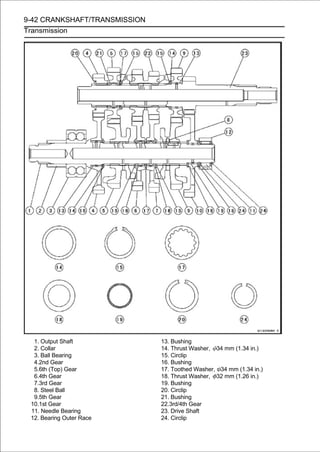
![CRANKSHAFT/TRANSMISSION 9-43
Transmission
Shift Drum and Fork Removal
•Split the crankcase (see Crankcase Splitting).
•Remove:
Gear Position Switch (see Gear Position Switch Re-
moval in the Electrical System chapter)
Screws [A]
Shift Drum Bearing Holder [B]
• Pull out the shift rods [A], and take off the shift forks [B].
• Pull out the shift drum [C].
Shift Drum and Fork Installation
• Apply engine oil to the shift drum, forks and rods.
• Install the shift drum [A].
• Install the fork [B] of the shortest ears on the drive shaft as
follows.
○Fit the ears on the groove of the 3rd/4th gear [C] and place the
pin in the center groove in the shift drum.
• Insert the rod (shorter side) [D].
• Apply a non-permanent locking agent to the threads of
the shift drum bearing holder screw, and tighten them.
Torque - Shift Drum Bearing Holder Screws: 5.0 N·m (0.51
kgf·m, 44 in·lb)
• Install in the grooves [E] bothshown in the shift drum. place
the pins
the two forks
on
as
sides
in the figure, and
○The two forks on the output shaft are identical.
• Insert the rod (longer side) [F].
Shift Drum Disassembly
• Remove the shift drum (see Shift Drum and Fork Re-
moval).
• While holding the shift drum with a vise, remove the shift
drum cam bolt [A].
• Remove:
Shift Drum Cam [B]
Dowel Pin [C]
Shift Drum Assembly
• Be sure to install the dowel pin.
• Apply a non-permanent locking agent to the threads of
the shift drum cam bolt, and tighten it.
Torque - Shift Drum Cam Bolt: 12 N·m (1.2 kgf·m, 104 in·lb)](https://image.slidesharecdn.com/2008-100321201635-phpapp01/85/2008-410-320.jpg)
![9-44 CRANKSHAFT/TRANSMISSION
Transmission
Shift Fork Bending
• Visually inspect the shift forks, and replace any fork that is
bent. A bent fork could cause difficulty in shifting, or allow
the transmission to jump out of gear when under power.
90° [A]
Shift Fork/Gear Groove Wear
• Measure the thickness of the shift fork ears [A], and measure
the width [B] of the gear grooves.
If the thickness of a shift fork ear is less than the service
limit, the shift fork must be replaced.
Shift Fork Ear Thickness
Standard: 5.9 ∼ 6.0 mm (0.232 ∼ 0.236 in.)
Service Limit: 5.8 mm (0.228 in.)
If the gear groove is worn over the service limit, the gear
must be replaced.
Gear Groove Width
Standard: 6.05 ∼ 6.15 mm (0.238 ∼ 0.242 in.)
Service Limit: 6.25 mm (0.246 in.)
Shift Fork Guide Pin/Drum Groove Wear
• Measure the diameter of each shift fork guide pin [A], and
measure the width [B] of each shift drum groove.
If the guide pin on any shift fork is less than the service
limit, the fork must be replaced.
Shift Fork Guide Pin Diameter
Standard: 5.9 ∼ 6.0 mm (0.232 ∼ 0.236 in.)
Service Limit: 5.8 mm (0.228 in.)
If any shift drum groove is worn over the service limit, the
drum must be replaced.
Shift Drum Groove Width
Standard: 6.05 ∼ 6.20 mm (0.238 ∼ 0.244 in.)
Service Limit: 6.3 mm (0.248 in.)
Gear Dog and Gear Dog Hole Damage
• Visually inspect the gear dogs [A] and gear dog holes [B].
Replace any damaged gears or gears with excessively
worn dogs or dog holes.](https://image.slidesharecdn.com/2008-100321201635-phpapp01/85/2008-411-320.jpg)
![CRANKSHAFT/TRANSMISSION 9-45
External Shift Mechanism
Shift Pedal Removal
•Remove:
Shift Lever Bolt [A]
Shift Lever [B]
If the tie-rod is removed from the shift pedal and shift lever,
note the following.
○The following portions have left-hand threads.
Shift Lever Side of Tie-Rod (The shift lever side of the
tie-rod has the grooves [C].)
Locknut [D] of Shift Lever Side
Ball Joint [E] of Shift Lever
• Remove:
Shift Pedal Mounting Bolt [A]
Tie-Rod [B] and Shift Pedal [C]
Shift Pedal Installation
• Apply grease to the sliding surface [A] on the sift pedal
mounting bolt [B].
• Apply a non-permanent locking agent to the thread of the
shift pedal mounting bolt.
• Install:
Washer [C]
Tie-Rod [D] and Shift Pedal [E]
• Tighten:
Torque - Shift Pedal Mounting Bolt: 25 N·m (2.5 kgf·m, 18
ft·lb)
• Align the punch mark [A] on the shift shaft with the slit [B] of
the shift lever.
• Tighten:
Torque - Shift Lever Bolt: 7.0 N·m (0.71 kgf·m, 62 in·lb)
• After installation, inconfirm that
positioned as shown the figure.
the shift pedal [C] is
About 20.8° [D]
About 90° [E]
If the pedal position is different, adjust it as follows.
○To adjust the pedal position, loosen the front locknut [F]
(left-hand threads) and rear locknut [G], and then turn the
tie-rod [H].
○Tighten:
Torque - Tie-Rod Locknuts: 7.0 N·m (0.71 kgf·m, 62 in·lb)](https://image.slidesharecdn.com/2008-100321201635-phpapp01/85/2008-412-320.jpg)
![9-46 CRANKSHAFT/TRANSMISSION
External Shift Mechanism
External Shift Mechanism Removal
•Remove:
Shift Lever (see Shift Pedal Removal)
Clutch (see Clutch Removal in the Clutch chapter)
Circlip [A]
Washer [B]
Special Tool - Outside Circlip Pliers: 57001-144
• Remove the shift shaft assembly, collar [A] while pulling
out the shift mechanism arm [B].
○Stuff the cloth [C] on the hole of the crankcase so that the
collar and spacer do not drop into the crankcase bottom.
• Remove the shift ratchet assembly holder bolts [A].
• Take[C]. the shift ratchet assembly [B] together with the
holder
off
○Pull out the shift ratchet assembly from the shift drum
cam.
• Remove:
Gear Positioning Lever Bolt [A]
Gear Positioning Lever [B]
Washer and Spring
External Shift Mechanism Installation
• Install the gear positioning lever [A] so that the bearing [B]
faces inside [C].
• Install:
Washer [D]
Spring [E]
• Tighten:
Torque - Gear Positioning Lever Bolt [F]: 12 N·m (1.2 kgf·m,
106 in·lb)](https://image.slidesharecdn.com/2008-100321201635-phpapp01/85/2008-413-320.jpg)
![CRANKSHAFT/TRANSMISSION 9-47
External Shift Mechanism
If the shift ratchet assembly was disassembled, assemble it
as shown in the figure.
Ratchet [A]
Pawls [B]
Pins [C]
Springs [D]
• Install the figure.
shown in the
shift ratchet assembly [A] on the holder [B] as
• Install the the shift drum cam [C]. [A] together with the
holder [B] on
shift ratchet assembly
○Insert the pawls [D] into the grooves [E] on the shift drum
cam.
• Turnthe shift ratchet assembly while pushing thethe figure.
Set
○ the shift ratchet assembly
[A] as shown in
pawls.
• Apply aholder bolts [B], and tighten them. the shift ratchet
assembly
non-permanent locking agent to
Torque - Shift Ratchet Assembly Holder Bolts: 15 N·m (1.5
kgf·m, 11 ft·lb)
• Apply grease to the lips of the grease seal [A].
• Apply engine oil to the needle bearing [B].](https://image.slidesharecdn.com/2008-100321201635-phpapp01/85/2008-414-320.jpg)
![9-48 CRANKSHAFT/TRANSMISSION
External Shift Mechanism
• Install the collar [A] on the shift ratchet assembly.
• Install the shiftalign with the collar and shift shaft return and
return spring [C]
shaft assembly so that the groove [B]
spring pin [D].
• Replace the circlip [A] with a new one.
• Install:
Washer [B]
Circlip
Special Tool - Outside Circlip Pliers: 57001-144
○Fit the circlip into the groove of the shift shaft securely.
External Shift Mechanism Inspection
• Examine the shift shaft [A] for any damage.
If the shaft is bent, straighten or replace it.
If the serration [B] are damaged, replace the shaft.
If the spring [C] is damaged in any way, replace it.
If the shift mechanism arm [D] is damaged in any way,
replace the shaft.
• Check the shift ratchet assembly for any damage.
If the ratchet [A], pawls [B], pins [C] or springs [D] are
damaged in any way, replace them.
• Check the return spring pin [A] is not loose.
If it is loose, unscrew it, apply a non-permanent locking
agent to the threads, and tighten it.
Torque - Shift Shaft Return Spring Pin: 29 N·m (3.0 kgf·m,
21 ft·lb)
• Check distortion. positioning lever [B] and its spring for
breaks or
the gear
If the lever or spring are damaged in any way, replace
them.
• Visually inspect the shift drum cam [C].
If they are badly worn or if they show any damage, replace
it.](https://image.slidesharecdn.com/2008-100321201635-phpapp01/85/2008-415-320.jpg)
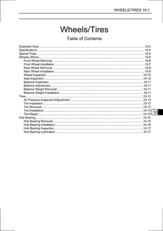
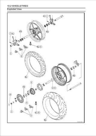
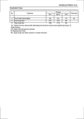
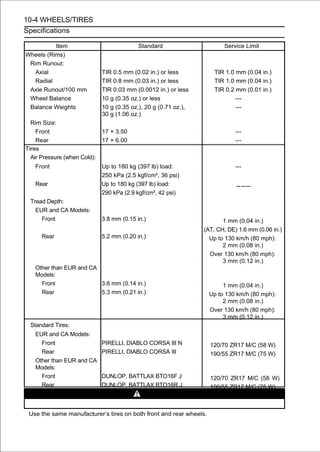
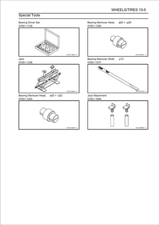
![10-6 WHEELS/TIRES
Wheels (Rims)
Front Wheel Removal
• Remove:
Front Caliper Mounting Bolts [A] (Both Sides)
Front Calipers [B] (Both Sides)
• Loosen:
Axle Clamp Bolts [A] (Right Side)
Axle [B]
• Removechapter). fairings (see Lower Fairing Removal in
the Frame
the lower
• Raise the front wheel off the ground with the jack [A].
Special Tools - Jack: 57001-1238
Jack Attachment: 57001-1608
• Pull frontthe axle to the right side and drop the front wheel out
of the
out
forks.
CAUTION
Do not lay the wheel down on one of the discs. This
can damage or warp the disc. Place blocks un-
der the wheel so that the disc does not touch the
ground.
• Loosen the axle clamp bolts (left side) [A] and remove the
axle nut [B].](https://image.slidesharecdn.com/2008-100321201635-phpapp01/85/2008-421-320.jpg)
![WHEELS/TIRES 10-7
Wheels (Rims)
Front Wheel Installation
NOTE
○The direction of the wheel rotation [A] is shown by an
arrow [B] on the wheel spoke.
• Check the wheel rotation mark on the front wheel and
install it.
• Apply high-temperature grease to the grease seal lips.
• Thethe collars [A] on the both sides of the hub.
Fit
○ collars are identical.
• side. the axle nut [B] and insert the axle [C] from the right
Install
Axle Clamp Bolts (Right Side) [D]
Axle Clamp Bolts (Left Side) [E]
Rear View [F]
• Tighten:
Torque - Front Axle Nut: 127 N·m (13.0 kgf·m, 94 ft·lb)
• Before tightening the axle clamp bolts, pump the front fork
up and down [A] 4 or 5 times to allow the right fork leg to
find a neutral position on the front axle.
NOTE
○Put a block [B] in front of the front wheel to stop moving.
• the axle the axlebolts onboltsleft forkright fork leg first, next,
Tighten
clamp
clamp
the
on the
leg.
Torque - Front Axle Clamp Bolts: 20 N·m (2.0 kgf·m, 15 ft·lb)
NOTE
○Tighten the two axle clamp bolts alternately two times to
ensure even tightening torque.
• the Frame chapter). (see Lower Fairing installation in
Install the lower fairing
• Brakes the front calipers (see Caliper Installation in the
Install
chapter).
• Inspection in thebrake effectiveness (seechapter).
Check the front
Periodic Maintenance
Brake Operation
WARNING
Do not attempt to drive the motorcycle until a full
brake lever is obtained by pumping the brake lever
until the pads are against the disc. The brake will
not function on the first application of the lever if
this is not done.](https://image.slidesharecdn.com/2008-100321201635-phpapp01/85/2008-422-320.jpg)
![10-8 WHEELS/TIRES
Wheels (Rims)
Rear Wheel Removal
•Raise the rear wheel off the ground with the stand [A].
• Remove:
Rear Caliper Mounting Bolts [A]
Rear Caliper [B]
• Remove:
Cotter Pin [A]
Axle Nut [B]
Washer [C]
• Pull out the axle [D] to the right side.
• Remove the drive chain [A] from the rear sprocket toward
the left.
• Move the rear wheel back and remove it.
CAUTION
Do not lay the wheel on the ground with the disc
facing down. This can damage or warp the disc.
Place blocks under the wheel so that the disc does
not touch the ground.
Rear Wheel Installation
• Apply high-temperature grease to the grease seal lips.
• Fit the collars [A] on the both sides of the hub.
○The collar of the rear sprocket side is large than the collar of
the brake disc side.](https://image.slidesharecdn.com/2008-100321201635-phpapp01/85/2008-423-320.jpg)
![WHEELS/TIRES 10-9
Wheels (Rims)
• Engage the drive chain with the rear sprocket.
• Install the caliper bracket [A] onto the stopper [B] ofthe
swingarm.
• Insert the axle from the right side of the wheel.
• Install the washer and axle nut.
• Adjust the drive chain slack before tightening Mainte- nut
(see Drive Chain Slack Inspection in the Periodic
the axle
nance chapter).
• Tighten:
Torque - Rear Axle Nut: 108 N·m (11.0 kgf·m, 80 ft·lb)
• Insert a new cotter pin [A].
NOTE
○When inserting the cotter pin, if the slots in the nut do
not align with the cotter pin hole in the axle, tighten the nut
clockwise [B] up to next alignment.
○It should be within 30 degree.
○Loosen once and tighten again when the slot goes past the
nearest hole.
• Bend the cotter pin [A] over the nut [B].
WARNING
If the rear axle nut is not securely tightened or the
cotter pin is not installed, an unsafe riding condition
may result.
• Install the rear caliper (see Caliper Installation in the
Brakes chapter).
• Check thethe Periodic Maintenance chapter). Operation
Inspection in
rear brake effectiveness (see Brake
WARNING
Do not attempt to drive the motorcycle until a full
brake pedal is obtained by pumping the brake pedal
until the pads are against the disc. The brake will
not function on the first application of the pedal if
this is not done.](https://image.slidesharecdn.com/2008-100321201635-phpapp01/85/2008-424-320.jpg)
![10-10 WHEELS/TIRES
Wheels (Rims)
Wheel Inspection
•Raise the front/rear wheel off the ground.
Special Tools - Jack: 57001-1238
Jack Attachment: 57001-1608
• roughnesswheel lightly, found, replace the hub bearings.
If
Spin the
or binding is
and check for roughness or binding.
• Inspect the wheel for small cracks, dents, bending, or
warp.
If there is any damage to the wheel, replace the wheel.
• Remove the wheel, and support it with the tire by the axle.
• Measure the rim runout, axial [A] and radial [B], with a dial
gauge.
If rim runout exceeds the service limit, check the hub bear-
ings.
If the problem is not due to the bearings, replace the
wheel.
Rim Runout (with tire installed)
Standard:
Axial TIR 0.5 mm (0.02 in.) or less
Radial TIR 0.8 mm (0.03 in.) or less
Service Limit:
Axial TIR 1.0 mm (0.04 in.)
Radial TIR 1.0 mm (0.04 in.)
WARNING
Never attempt to repair a damaged wheel. If there
is any damage besides wheel bearings, the wheel
must be replaced to insure safe operational condi-
tion.
Axle Inspection
• Remove the front/rear axle (see Front/Rear Wheel Re-
moval).
• Visually inspect the front and rear axle for damages. If
the axle is damaged or bent, replace it.
• Place the axle in V blocks that are 100 mm (3.94 in.) [A]
apart, and set a dial gauge [B] on the axle at a point
halfway between the blocks. Turn [C] the axle to mea-
sure the runout. The difference between the highest and
lowest dial readings is the amount of runout.
If axle runout exceeds the service limit, replace the axle.
Axle Runout/100 mm (3.94 in.)
Standard: TIR 0.03 mm (0.0012 in.) or less
Service Limit: TIR 0.2 mm (0.01 in.)](https://image.slidesharecdn.com/2008-100321201635-phpapp01/85/2008-425-320.jpg)
![WHEELS/TIRES 10-11
Wheels (Rims)
Balance Inspection
• Remove the front/rear wheel (see Front/Rear Wheel Re-
moval).
• Support the wheel so that it can be spun freely.
• Spin the wheel lightly, and mark [A] the wheel at the top
when the wheel stops.
○Repeat this procedure several times. If the wheel stops
of its own accord in various positions, it is well balanced.
If the wheel always stops in one position, adjust the wheel
balance (see Balance Adjustment).
Balance Adjustment
• If the wheel always stops in one position, provisionally
attach a balance weight [A] on the rim at the marking using
adhesive tape.
• Rotate the wheel 1/4 turn [B], and see whether or not the
wheel stops in this position. If it does, the correct balance
weight is being used.
If the wheel rotates and the weight goes up, replace the
weight with the next heavier size. If the wheel rotates and the
weight goes down, replace the weight with the next lighter
size. Repeat these steps until the wheel remains at rest
after being rotated 1/4 turn.
• Rotate the wheel another 1/4 turn and then another 1/4
turn to see if the wheel is correctly balanced.
• Repeat the entire procedure as many times as necessary to
achieve correct wheel balance.
• Permanently install the balance weight.
Balance Weight Removal
• Insert a regular tip screwdrivers [A] [B] between the rib [C]
and weight [D] as shown in the figure.
• Pry the balance weight with two screwdrivers and remove
the balance weight.
• Discard the used balance weight.
CAUTION
Do not tap the screwdrivers. The rim could be dam-
aged.
Balance Weight Installation
• Check if the weight portion has any play on the blade [A]
and clip [B].
Rear View [C]
Left Side [D]
If it does, discard it.
WARNING
If the balance weight has any play on the rib of the
rim, the blade and/or clip have been stretched.
Replace the loose balance weight.
Do not reuse used balance weight.
Unbalanced wheels can create an unsafe riding
condition.](https://image.slidesharecdn.com/2008-100321201635-phpapp01/85/2008-426-320.jpg)
![10-12 WHEELS/TIRES
Wheels (Rims)
Balance Weight
Part Number Weight
41075-0007 10 g (0.35 oz.)
41075-0008 20 g (0.71 oz.)
41075-0009 30 g (1.06 oz.)
NOTE
○Balance weights are available from Kawasaki dealers
in 10, 20 and 30 gram (0.35 oz., 0.71 oz. and 1.06 oz.)
sizes. An imbalance of less than 10 grams (0.35 oz.)
will not usually affect running stability.
○Do not use four or more balance weight (more than 90
gram). If the wheel requires an excess balance weight,
disassemble the wheel to find the cause.
• Sliphammering [C] the clip [D]. to the rib [B], by pushing or
lightly
the balance weight [A] on
Rear View [E]
Left Side [F]
• Be sure to install the balance weight.
○Check that the blade [A] and clip [B] are fully seated on
the rim [C] and that the clip is hooked over the rib [D].
Rear View [E]
Left Side [F]](https://image.slidesharecdn.com/2008-100321201635-phpapp01/85/2008-427-320.jpg)
![WHEELS/TIRES 10-13
Tires
Air Pressure Inspection/Adjustment
• Refer to the Tires Air Pressure Inspection in the Periodic
Maintenance chapter.
Tire Inspection
• Refer to the Wheels/Tires Damage Inspection in the
Periodic Maintenance chapter.
Tire Removal
• Remove:
Front/Rear Wheel (see Front/Rear Wheel Removal)
Valve Core (Let out the air)
• To maintain chalk so that themarkcan be reinstalledposition
on the tire with
wheel balance,
tire
the valve stem
in
the same position.
Chalk Mark or Yellow Mark [A]
Valve Stem [B]
Align [C]
• soap and watertire beadsorand rim lubricant.on both sides with
a
Lubricate the
solution rubber
flanges
This helps
the tire beads slip off the rim flanges.
CAUTION
Never lubricate with engine oil or petroleum
distillates because they will deteriorate the tire.
• Remove available tire changer. rim
commercially
the tire from the using a suitable
NOTE
○The tires can not be removed with hand tools because
they fit the rims too tightly.
Tire Installation
WARNING
Use the same manufacture’s on both front and rear
wheels.
• Inspect the rim and tire, and replace them if necessary.
• Clean the sealing of the rim with a fine emery cloth if smooth
the sealing surfaces
surfaces of the rim and tire, and
necessary.
• Remove the air valve and discard it.
CAUTION
Replace the air valve whenever the tire is replaced.
Do not reuse the air valve.](https://image.slidesharecdn.com/2008-100321201635-phpapp01/85/2008-428-320.jpg)
![10-14 WHEELS/TIRES
Tires
• Install a new valve in the rim.
○Remove the valve cap, lubricate the stem seal [A] with a
soap and water solution or rubber lubricant, and pull [B]
the valve stem through the rim from the inside out until it
snaps into place.
CAUTION
Do not use engine oil or petroleum distillates to lu-
bricate the stem because they will deteriorate the
rubber.
○The air valve is shown in the figure.
Valve Cap [A]
Valve Core [B]
Stem Seal [C]
Valve Stem [D]
Valve Seat [E]
Valve Opened [F]
• Check the tire rotation mark on the front and rear tires and
install them on the rim accordingly.
Tire Rotation Mark [A]
Rotating Direction [B]
• Position the tire on the [B] (the that the valve stem [A] align
with the tire balance mark
rim so
chalk mark made during
removal, or the yellow paint mark on a new tire).
• Install the tire bead over the rim flange using a suitable
commercially available tire changer.
• Lubricate the tire beads and rim flanges with a soap and
water solution or rubber lubricant to help seat the tire
beads in the sealing surfaces of the rim while inflating the
tire.
• Center the rim in the tire beads, and inflate the tire with
compressed air until the tire beads seat in the sealing
surfaces.
WARNING
Be sure to install the valve core whenever inflating
the tire, and do not inflate the tire to more than 400
kPa (4.0 kgf/cm², 57 psi). Overinflation can explode
the tire with possibility of injury and loss of life.](https://image.slidesharecdn.com/2008-100321201635-phpapp01/85/2008-429-320.jpg)
![WHEELS/TIRES 10-15
Tires
• Check aresee that with rim rim flanges. both sides of the tire
sidewalls
to
parallel
the
the
lines [A] on
If the rim flanges and tire sidewall rim lines are not parallel,
remove the valve core.
• Lubricate the rim flanges and tire beads.
• Install the valve core and inflate the tire again.
• After the tire beads seat in the rim flanges, check for air
leakage.
○Inflate the tire slightly above standard inflation.
○Use a soap and water solution or submerge the tire, and
check for bubbles that would indicate leakage.
• Adjust the air pressure to the specified pressure (see Air
Pressure Inspection in the Periodic Maintenance chap-
ter).
• Install the air valve cap.
• Adjust the wheel balance (see Balance Adjustment).
Tire Repair
Currently two types of repair for tubeless tires have come
into wide use. One type is called a temporary (external) re-
pair which can be carried out without removing the tire from
the rim, and the other type is called permanent (internal)
repair which requires tire removal. It is generally under-
stood that higher running durability is obtained by perma-
nent (internal) repairs than by temporary (external) ones.
Also, permanent (internal) repairs have the advantage of
permitting a thorough examination for secondary damage
not visible from external inspection of the tire. For these
reasons, Kawasaki does not recommend temporary (exter-
nal) repair. Only appropriate permanent (internal) repairs
are recommended. Repair methods may vary slightly from
make to make. Follow the repair methods indicated by the
manufacturer of the repair tools and materials so that safe
results can be obtained.](https://image.slidesharecdn.com/2008-100321201635-phpapp01/85/2008-430-320.jpg)
![10-16 WHEELS/TIRES
Hub Bearing
Hub Bearing Removal
• Remove the front/rear wheel (see Front/Rear Wheel
Removal), and take out the following parts.
Collars
Coupling (Out of Rear Wheel)
Grease Seals
• Use the bearing remover to remove the hub bearing [A].
CAUTION
Do not lay the wheel on the ground with the disc
facing down. This can damage or warp the disc.
Place blocks under the wheel so that the disc does
not touch the ground.
Special Tools - Bearing Remover Head, 20 × 22: 57001
-1293 (For Rear Wheel)
Bearing Remover Head, 25 × 28 [B]:
57001-1346 (For Front Wheel)
Bearing Remover Shaft, 13 [C]: 57001
-1377
Hub Bearing Installation
• Before installing the wheel bearings, blow any dirt or for-
eign particles out of the hub with compressed air to pre-
vent contamination of the bearings.
• Replace the bearings with new ones.
NOTE
○Install the bearings so that the marked side faces out.
• Install contact the bearing inner race. driver set which
does not
the bearings by using the bearing
• Press in each right the bearing [A] until they are bottomed.
Special Tool - Bearing Driver Set [B]: 57001-1129
○Before pressing in the bearing of the other side, install the
sleeve [C].
• Replace the grease seals with new ones.
• Press with the end ofseals [A] so that the seal surface is
flush [B]
in the grease
the hole.
○Apply high-temperature grease to the grease seal lips.
Special Tool - Bearing Driver Set [C]: 57001-1129](https://image.slidesharecdn.com/2008-100321201635-phpapp01/85/2008-431-320.jpg)
![WHEELS/TIRES 10-17
Hub Bearing
Hub Bearing Inspection
Since the hub bearings are made to extremely close tol-
erances, the clearance can not normally be measured.
NOTE
○Do not remove any bearings for inspection. If any bear-
ings are removed, they will need to be replaced with
new ones.
• Turn eachplays, roughness,hubbinding.and forth [A] while
checking for
bearing in the
or
back
If bearing play, roughness, or binding is found, replace
the bearing.
• Examine the bearing seal [B] for tears or leakage.
If the seal is torn or is leaking, replace the bearing.
Hub Bearing Lubrication
NOTE
○Since the hub bearings are packed with grease and
sealed, lubrication is not required.](https://image.slidesharecdn.com/2008-100321201635-phpapp01/85/2008-432-320.jpg)

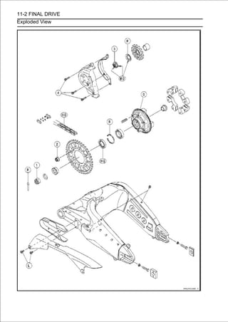
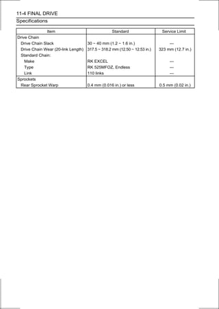
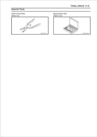
![11-6 FINAL DRIVE
Drive Chain
Drive Chain Slack Inspection
• Refer to the Drive Chain Slack Inspection in the Periodic
Maintenance chapter.
Drive Chain Slack Adjustment
• Refer to the Drive Chain Slack Inspection in the Periodic
Maintenance chapter.
Wheel Alignment Inspection/Adjustment
•Refer to the Wheel Alignment Inspection in the Periodic
Maintenance chapter.
Drive Chain Wear Inspection
• Refer to the Drive Chain Wear Inspection in the Periodic
Maintenance chapter.
Drive Chain Lubrication
• Refer to the Drive Chain Lubrication Condition in the
Periodic Maintenance chapter.
Drive Chain Guide Wear Inspection
• Refer to the Drive Chain Guide Wear Inspection in the
Periodic Maintenance chapter.
Drive Chain Removal
NOTE
○Since the drive chain is installed through the swingarm,
The chain can not be removed other than by cutting it.
Prepare the new link pin, link plate, grease seals, and
tools for rejoining the chain.
• Remove:
Bolts [A]
Front Footpeg Bracket [B]
• Remove:
Bolts [A]
Quick Rivet [B]
Chain Cover [C]
○Push the central pin, and then remove the quick rivet.](https://image.slidesharecdn.com/2008-100321201635-phpapp01/85/2008-439-320.jpg)
![FINAL DRIVE 11-7
Drive Chain
• link pins.suitable tool, cut the drive chain by removing the
Using a
Recommended Tool: RK EXCEL 70 or 90 Tool (RK-700
or RK-90)
CAUTION
Read the Tool Manual before cutting the drive chain.
Pressure Bolt (a) [A]
Pressure Bolt (b) [B]
Handle Lever [C]
Pressure Holder [D]
Guide Plate [E]
Adjuster Bolt (Yellow) [F]
Wedge Holder [G] and Wedge Pin
Grip Handle [H]
Flare Pin [I]
Cap [J]
Adjuster Bolt [K]
Pin Puller [L]
Body [N]
Cap Bolt [M]
• Install the guide plate [A] on the body [B].
• Screw the cap bolt [C].
• Install the grip handle.
• Set the chain [A] to the guide plate [B].
• Screw in the adjuster bolt [C] for holding the chain.
• Screw in the pressure bolt (a) [D] for holding the chain.
• Insert the pin puller [A] to the pressure bolt (b) [B].](https://image.slidesharecdn.com/2008-100321201635-phpapp01/85/2008-440-320.jpg)
![11-8 FINAL DRIVE
Drive Chain
• Screw in the pressure bolt assy [A] in the pressure bolt
(a) [B].
• Install the handle lever [C] to the pressure bolt assy.
• Turn plate [E]. lever until the link pin [D] removed at
the link
in the handle
• Repeat the above steps for other link pin [A].
Drive Chain Installation
• Engage new drive chain to the old drive chain and pull
the end of the old drive chain until they are changing the
position.
• Remove the old drive chain from the new drive chain.
• Apply grease to the link pins [A] and grease seals [B] [C].
• Engage the drive chain on the rear sprocket through the
swingarm.
• Install the grease seals [B] on the link pins.
• Insert the link pins in the drive chain ends from the inside.
• Install the grease seals [C].
• Install the link plate so that the gold painted [A] faces out-
side.
• Push thetolink plategrease sealsplier to fix it.
○Be sure set the
by hand or
correctly.
• Set the adjusterholder [C] on the body [D]. and wedge pin
[B], and pressure
bolt (yellow) [A], wedge holder
• Hold the wedge holder and wedge pin, using the adjuster
bolt (yellow).
• Apply grease to the inside [E] of the pressure holder.](https://image.slidesharecdn.com/2008-100321201635-phpapp01/85/2008-441-320.jpg)
![FINAL DRIVE 11-9
Drive Chain
• Fit the link plate [A] in the pressure holder [B].
• Fit the link plates of the chain into the wedge holder and
wedge pin [D].
• Turn the link pins. bolt (a) [C] by hand until link plate
touches the
pressure
• Install the handle lever [A] onto the pressure bolt (a) [B].
• Turn the handle lever, press in the link plate to the link
pins.
• Set the adjuster bolt (yellow) [A], guide plate [B], and flare pin
[C] on the body.
• Apply grease to the tip [D] of the flare pin.
• Fit the adjuster bolt (yellow) to the link pin [E].
• Install the grip lever [A] onto the pressure bolt (a) [B].
• Stake the link pin end by the handle lever about 9/10 turns
[C].
• Repeat the above steps for other link pin [D].](https://image.slidesharecdn.com/2008-100321201635-phpapp01/85/2008-442-320.jpg)
![11-10 FINAL DRIVE
Drive Chain
• After staking, check the staked area of the link pin for
cracks.
• Measure the outside diameter [A] of the link pin and link
plates width [B].
Link Pin Outside Diameter
Standard: 5.6 ∼ 5.9 mm (0.22 ∼ 0.23 in.)
Link Plates Outside Width
Standard: 19.7 ∼ 20.0 mm (0.775 ∼ 0.787 in.)
If the reading exceeds the specified length, cut and rejoin the
chain again.
• Check the movement of the rollers.
• Adjust theSlack Adjustment inafter Periodic Mainte- (see
Drive Chain
drive chain slack
the
installing the chain
nance chapter).
• When installing the chain cover [A], note the following.
○Apply a non-permanent locking agent to the bolt [B] only.
• Install the front footpeg bracket.
Torque - Front Footpeg Bracket Bolts: 25 N·m (2.5 kgf·m,
18 ft·lb)](https://image.slidesharecdn.com/2008-100321201635-phpapp01/85/2008-443-320.jpg)
![FINAL DRIVE 11-11
Sprocket, Coupling
Engine Sprocket Removal
•Remove:
Engine Sprocket Cover Bolts [A]
Engine Sprocket Cover [B]
• Flatten out the bended washer [A].
• Remove the engine sprocket nut [B] and washer.
NOTE
○When loosening the engine sprocket nut, hold the rear
brake on.
• Raise the rear wheel off the ground with stand.
• Loosen inthe Periodicchain (see Drive Chain Slack
Adjustment the
drive
Maintenance chapter).
• Remove the drive chain from the rear sprocket toward the
right.
• Pull shaftengine sprocket [A] with drive chain [B] off the
output
the
[C].
• Disengage the drive chain from the engine sprocket.
Engine Sprocket Installation
• Replace the sprocket washer with a new one.
• Install the engine sprocket onto the output shaft.
• Apply molybdenum disulfide oil solution to the threads of
the output shaft and the seating surface of the engine
sprocket nut.
• Tighten:
Torque - Engine Sprocket Nut: 125 N·m (12.7 kgf·m, 92 ft·lb)
NOTE
○Tighten the engine sprocket nut while applying the rear
brake.
• Afterthe washer overengine sprocket nut, bend [B] the one
side of
tightening the
the nut.
• Adjust the drive chain slack after installing theMain-
(see Drive Chain Slack Adjustment in the Periodic
sprocket
tenance chapter).](https://image.slidesharecdn.com/2008-100321201635-phpapp01/85/2008-444-320.jpg)
![11-12 FINAL DRIVE
Sprocket, Coupling
• Fit the projection [A] guide [D]. sprocket cover [B] into
the slot [C] of the chain
of the engine
• Fit the of the[A] of the engine sprocket cover [B] into the
holes [C]
pins
crankcase.
• Tighten:
Torque - Engine Sprocket Cover Bolts: 10 N·m (1.0 kgf·m,
89 in·lb)
Rear Sprocket Removal
•Remove the rear wheel (see Rear Wheel Removal in the
Wheels/Tires chapter).
CAUTION
Do not lay the wheel on the ground with the disc
facing down. This can damage or warp the disc.
Place blocks under the wheel so that the disc does
not touch the ground.
• Remove:
Rear Sprocket Nuts [A]
Rear Sprocket [B]
Rear Sprocket Installation
• Install the sprocket facing the tooth number marking [A]
outward.
• Tighten the rear sprocket nuts.
Torque - Rear Sprocket Nuts: 59 N·m (6.0 kgf·m, 44 ft·lb)
• Install the rear wheel (see Rear Wheel Installation in the
Wheels/Tires chapter).](https://image.slidesharecdn.com/2008-100321201635-phpapp01/85/2008-445-320.jpg)
![FINAL DRIVE 11-13
Sprocket, Coupling
Coupling Installation
• Apply high-temperature grease to the coupling grease
seal lips [A].
• Apply grease to the coupling internal surface [B].
• Apply grease to the new O-ring [A].
• Install the collar [B].
Coupling Bearing Removal
•Remove:
Coupling
Grease Seal
Circlip [A]
Special Tool - Inside Circlip Pliers: 57001-143
• Remove the bearing [A] by tapping from the wheel side.
Special Tool - Bearing Driver Set [B]: 57001-1129
Coupling Bearing Installation
•Replace the bearing with a new one.
•Press in the bearing [A] until it is bottomed.
Special Tool - Bearing Driver Set [B]: 57001-1129
• Replace the circlip with a new one.
Special Tool - Inside Circlip Pliers: 57001-143](https://image.slidesharecdn.com/2008-100321201635-phpapp01/85/2008-446-320.jpg)
![11-14 FINAL DRIVE
Sprocket, Coupling
• Replace the grease seal with a new one.
• Press withthe grease the hole. so that the seal surface is
flush [B]
in
the end of
seal [A]
○Apply high-temperature grease to the grease seal lips.
Special Tool - Bearing Driver Set [C]: 57001-1129
Coupling Bearing Inspection
Since the coupling bearing is made to extremely close
tolerances, the clearance can not normally be measured.
NOTE
○It is not necessary to remove the coupling bearing for
inspection. If the bearing is removed, it will need to be
replaced with a new one.
• Turn the bearingroughness, or binding. and forth [A] while
checking for plays,
in the coupling back
If bearing play, roughness, or binding is found, replace
the bearing.
• Examine the bearing seal [B] for tears or leakage.
If the seal is torn or is leaking, replace the bearing.
Coupling Bearing Lubrication
NOTE
○Since the coupling bearing is packed with grease and
sealed, lubrication is not required.
Coupling Damper Inspection
• Remove the coupling, and inspect the rubber dampers
[A].
• Replace the damper if it appears damaged or deterio-
rated.
Sprocket Wear Inspection
• Visually inspect the engine and rear sprocket teeth for
wear and damage.
If the teeth are worn as illustrated, replace the sprocket,
and inspect the drive chain wear (see Drive Chain Wear
Inspection in the Periodic Maintenance chapter).
Worn Tooth (Engine Sprocket) [A]
Worn Tooth (Rear Sprocket) [B]
Direction of Rotation [C]
NOTE
○If a sprocket requires replacement, the chain is proba-
bly worn also. When replacing a sprocket, inspect the
chain.](https://image.slidesharecdn.com/2008-100321201635-phpapp01/85/2008-447-320.jpg)
![FINAL DRIVE 11-15
Sprocket, Coupling
Rear Sprocket Warp Inspection
• Raise the rear wheel off the ground with stand so that it
will turn freely.
• Set a dial gauge [A] against the rear sprocket [B] near the
teeth as shown, and rotate [C] the rear wheel to measure
the sprocket runout (warp). The difference between the
highest and lowest dial gauge readings is the amount of
runout (warp).
If the runout exceeds the service limit, replace the rear
sprocket.
Rear Sprocket Warp
Standard: 0.4 mm (0.016 in.) or less
Service Limit: 0.5 mm (0.02 in.)](https://image.slidesharecdn.com/2008-100321201635-phpapp01/85/2008-448-320.jpg)

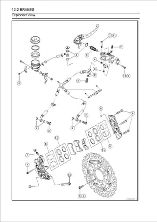
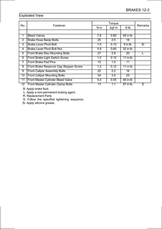
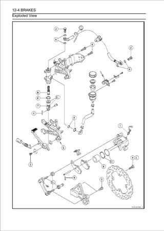
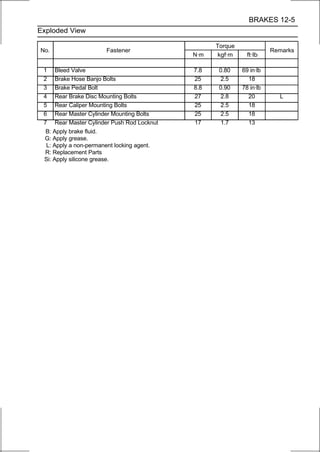
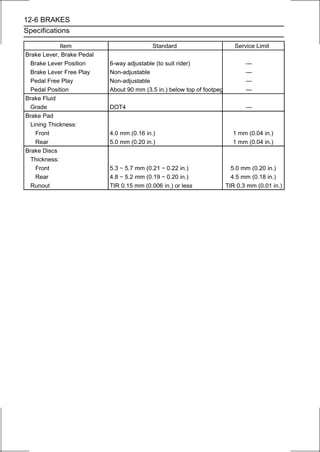
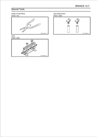
![12-8 BRAKES
Brake Lever, Brake Pedal
Brake Lever Position Adjustment
The brake lever adjuster has 6 positions so that the brake
lever position can be adjusted to suit the operator’s hand.
• Push the lever forward and turn the adjuster [A] to align
the number with the arrow mark [B] on the lever holder.
○The distance from the grip to the lever is minimum at number
6 and maximum at number 1.
Brake Pedal Position Inspection
• Check that the brake pedal [A] is in the correct position.
Footpeg [B]
Pedal Position
Standard: About 90 mm (3.5 in.) [C] below top of
footpeg
If it is incorrect, adjust the brake pedal position.
Brake Pedal Position Adjustment
NOTE
○Usually it is not necessary to adjust the pedal position,
but always adjust it when push rod locknut has been
loosened.
• Loosen the locknut [A] and pedalthe push rod with the hex
head [B] to achieve the correct
turn
position.
If the length [C] shown is 70 ±1 mm (2.8 ±0.04 in.), the
pedal position will be within the standard range.
• Tighten:
Torque - Rear Master Cylinder Push Rod Locknut: 17 N·m
(1.7 kgf·m, 13 ft·lb)
• Check theOperation Inspection in theoperation Mainte-
Light Switch
rear brake light switch
Periodic
(see Brake
nance chapter).
Brake Pedal Removal
• Remove:
Rear Master Cylinder Mounting Bolts [A]
Foot Guard [B]
Front Footpeg Bracket Bolts [C]](https://image.slidesharecdn.com/2008-100321201635-phpapp01/85/2008-457-320.jpg)
![BRAKES 12-9
Brake Lever, Brake Pedal
• Remove:
Cotter Pin [A]
Joint Pin [B]
Rear Brake Light Switch Spring [C]
Return Spring [D]
• Remove the mounting bolt [E] and take out the brake
pedal.
Brake Pedal Installation
• Apply grease to the pivot shaft [A].
• Install:
Washer [B]
Brake Pedal [C]
Washer [D]
Brake Pedal Bolt [E]
•Tighten:
Torque - Brake Pedal Bolt: 8.8 N·m (0.90 kgf·m, 78 in·lb)
• Hook bracket [B] as shown inon the brake pedal and front
footpeg
the return spring [A]
the figure.
• Hook the rear as shown inswitch spring [C] on the switch
and return spring
brake light
the figure.
Outside [D]
Rear View [E]
• Replace the cotter pin [A] with a new one.
• Insert the cotter pin and bend the pin ends [B].](https://image.slidesharecdn.com/2008-100321201635-phpapp01/85/2008-458-320.jpg)
![12-10 BRAKES
Brake Lever, Brake Pedal
• Install the front footpeg bracket.
Torque - Front Footpeg Bracket Bolts: 25 N·m (2.5 kgf·m,
18 ft·lb)
• Install the rear master cylinder [A] and foot guard [B].
NOTE
○Depress the brake pedal [C] and then align the holes of the
master cylinder.
○After installation, check that the rear brake light switch
spring is hooked on the return spring.
• Tighten:
Torque - Rear Master Cylinder Mounting Bolts: 25 N·m (2.5
kgf·m, 18 ft·lb)
• Check the brake pedal position (see Brake Pedal Position
Inspection).](https://image.slidesharecdn.com/2008-100321201635-phpapp01/85/2008-459-320.jpg)
![BRAKES 12-11
Calipers
Front Caliper Removal
• Loosen the banjo bolt [A] at the brake hose lower end,
and tighten it loosely.
• Unscrew the caliper mounting bolts [B], and detach the
caliper [C] from the disc.
CAUTION
Do not loosen the caliper assembly bolts [D]. Take
out only the caliper mounting bolts for caliper
removal. Loosening the caliper assembly bolts will
cause brake fluid leakage.
• Unscrew the banjo bolt and remove the brake hose [E]
from the caliper (see Brake Hose and Pipe Replacement in
the Periodic Maintenance chapter).
CAUTION
Immediately wash away any brake fluid that spills.
NOTE
○If the caliper is to be disassembled after removal and if
compressed air is not available, disassemble the caliper
before the brake hose is removed (see Caliper Rubber
Parts Replacement in the Periodic Maintenance chap-
ter).
• Remove the collars [A] from the fork leg.
Rear Caliper Removal
• Loosen the banjo bolt [A] at the brake hose lower end,
and tighten it loosely.
• Unscrew the caliper mounting bolts [B], and detach the
caliper [C] from the disc.
• Unscrew the banjo bolt and remove the brake hose [D]
from the caliper (see Brake Hose and Pipe Replacement
in the Periodic Maintenance chapter).
CAUTION
Immediately wash away any brake fluid that spills.
NOTE
○If the caliper is to be disassembled after removal and if
compressed air is not available, disassemble the caliper
before the brake hose is removed (see Caliper Rubber
Parts Replacement in the Periodic Maintenance chap-
ter).](https://image.slidesharecdn.com/2008-100321201635-phpapp01/85/2008-460-320.jpg)
![12-12 BRAKES
Calipers
Caliper Installation
• Install the caliper and brake hose lower end.
○For the front caliper, install the collars [A] on the fork leg
and fit the holes [B] of the front caliper to the collars.
○Replace the washers on each side of hose fitting with new
ones.
• Tighten:
Torque - Caliper Mounting Bolts
Front: 34 N·m (3.5 kgf·m, 25 ft·lb)
Rear: 25 N·m (2.5 kgf·m, 18 ft·lb)
Brake Hose Banjo Bolts: 25 N·m (2.5 kgf·m, 18
ft·lb)
• Bleed the brake line (see Brake Line Bleeding).
• Check theleakage.for good braking power, no brake drag,
and no fluid
brake
WARNING
Do not attempt to drive the motorcycle until a full
brake lever or pedal is obtained by pumping the
brake lever or pedal until the pads are against the
disc. The brakes will not function on the first appli-
cation of the lever or pedal if this is not done.
Front Caliper Disassembly
• Refer to the Caliper Rubber Parts Replacement in the
Periodic Maintenance chapter.
Front Caliper Assembly
• Refer to the Caliper Rubber Parts Replacement in the
Periodic Maintenance chapter.
Rear Caliper Disassembly
• Refer to the Caliper Rubber Parts Replacement in the
Periodic Maintenance chapter.
Rear Caliper Assembly
• Refer to the Caliper Rubber Parts Replacement in the
Periodic Maintenance chapter.](https://image.slidesharecdn.com/2008-100321201635-phpapp01/85/2008-461-320.jpg)
![BRAKES 12-13
Calipers
Caliper Fluid Seal Damage
The fluid seal (piston seal) [A] is placed around the pis-
ton to maintain clearance between the pad and the disc. If
the seal is in a poor condition, it could lead the pad to wear
excessively or the brake to drag, which may cause the tem-
perature of the discs or the brake fluid to increase.
• Replace the fluid seal if it exhibits any of the conditions
listed below.
○Brake fluid leakage around the pad.
○Brakes overheat.
○Considerable difference in inner and outer pad wear.
○Seal and piston are stuck together.
If the fluid seal is replaced, replace the dust seal [B] as
well. Also, replace all seals every other time the pads are
changed.
Front Caliper [C]
Rear Caliper [D]
Rear Caliper Dust Boot and Friction Boot Damage
• Check that the dust boot [A] and friction boot [B] are not
cracked, worn, swollen, or otherwise damaged.
If they show any damage, replace it.
Caliper Piston and Cylinder Damage
• Visually inspect the pistons [A] and cylinder surfaces [B].
Replace the caliper if the cylinder and piston are badly
scores or rusty.
Front Caliper [C]
Rear Caliper [D]](https://image.slidesharecdn.com/2008-100321201635-phpapp01/85/2008-462-320.jpg)
![12-14 BRAKES
Calipers
Rear Caliper Holder Shaft Wear
The caliper body must slide smoothly on the caliper holder
shafts [A]. If the body does not slide smoothly, one pad will
wear more than the other, pad wear will increase, and con-
stant drag on the disc will raise brake and brake fluid tem-
perature.
• Check to see that the caliper holder shafts are not badly
worn or stepped, and that the rubber friction boots are not
damaged.
If the rubber friction boot is damaged, replace the rubber
friction boot. To replace the friction boot, remove the pads
and the caliper bracket.
If the caliper holder shaft is damage, replace the caliper
bracket.](https://image.slidesharecdn.com/2008-100321201635-phpapp01/85/2008-463-320.jpg)
![BRAKES 12-15
Brake Pads
Front Brake Pad Removal
• Loosen the pad pins [A].
• Remove the front caliper with the hose installed (see Front
Caliper Removal).
• Remove:
Pad Pins [A]
Brake Pads [B]
Front Brake Pad Installation
• Check that the pad spring [A] is in place on the caliper.
• Push the caliper pistons in by hand as far as they will go.
• Install the brake pads on the pad spring correctly.
○Fit the pad [A] into the groove of the caliper as shown in
the figure.
• Install the pad pins while pushing the brake pads lightly.
• Tighten the pad pins temporarily.
• Install the front caliper (see Caliper Installation).
• Tighten:
Torque - Front Brake Pad Pins: 15 N·m (1.5 kgf·m, 11 ft·lb)
WARNING
Do not attempt to drive the motorcycle until a full
brake lever is obtained by pumping the brake lever
until the pads are against the disc. The brake will
not function on the first application of the lever if
this is not done.](https://image.slidesharecdn.com/2008-100321201635-phpapp01/85/2008-464-320.jpg)
![12-16 BRAKES
Brake Pads
Rear Brake Pad Removal
• Remove the rear caliper with the hose installed (see Rear
Caliper Removal).
• Remove:
Clip [A]
Pad Pin [B]
• Remove the brake pad [C] of the jaw side from the holder
shaft [D], then remove the other pad [E].
Rear Brake Pad Installation
• Check that the pad spring [A] and guide [B] are in place on
the caliper and holder.
• Push the caliper piston in by hand as far as it will go.
• Install the brake pad [A] on the piston side first, then install the
other pad on the holder shaft.
○Fit the projections [B] of the piston side pad into the
recesses [C] of the caliper holder.
• Install the pad pin while pushing the brake pad of the jow
side lightly.
• Install a new clip.
○The clip must be “outside” of the pad.
• Install the rear caliper (see Rear Caliper Installation).
WARNING
Do not attempt to drive the motorcycle until a full
brake pedal is obtained by pumping the brake pedal
until the pads are against the disc. The brake will
not function on the first application of the pedal if
this is not done.
Brake Pad Wear Inspection
• Refer to the Brake Pad Wear Inspection in the Periodic
Maintenance chapter.](https://image.slidesharecdn.com/2008-100321201635-phpapp01/85/2008-465-320.jpg)
![BRAKES 12-17
Master Cylinder
Front Master Cylinder Removal
• Remove the reservoir mounting bolt and nut [A].
• Unscrew the banjo bolt [A]Brakeremove thePipe Re-hose
from the master cylinder (see
and
Hose and
brake
placement in the Periodic Maintenance chapter).
• Unscrew the clamp bolts [B], and take off the master cylin-
der as an assembly with the reservoir, brake lever, and
front brake light switch installed.
• Disconnect the front brake light switch connector [C].
CAUTION
Immediately wash away any brake fluid that spills.
• Remove:
Brake Lever Pivot Bolt [A] and Nut [B]
Brake Lever [C]
Clamp [D] (Slide Out)
Brake Hose [E]
Front Brake Light Switch [F]
Front Master Cylinder Installation
• Apply silicone grease to the sliding surface of the brake
lever pivot bolt.
• Tighten:
Torque - Brake Lever Pivot Bolt: 1.0 N·m (0.10 kgf·m, 9
in·lb)
Brake Lever Pivot Bolt Nut: 5.9 N·m (0.60 kgf·m,
52 in·lb)
• Install the front brake light switch.
Torque - Front Brake Light Switch Screw: 1.2 N·m (0.12
kgf·m, 11 in·lb)](https://image.slidesharecdn.com/2008-100321201635-phpapp01/85/2008-466-320.jpg)
![12-18 BRAKES
Master Cylinder
• Install facesmaster cylinder clamp [A] so that the arrow
mark [B]
the
upward.
○There will be a gap at the lower part of the clamp.
• Install the masterclamp is aligned with the punch mark [A] of
the master cylinder
cylinder so that the mating surface
[B] of the handlebar.
• Tighten the upper clamp bolt first, then the lower clamp
bolt.
Torque - Front Master Cylinder Clamp Bolts: 11 N·m (1.1
kgf·m, 97 in·lb)
• Connect the front brake light switch connector [A] as
shown in the figure.
Left Side View [B]
Front [C]
• Replace the washers on each side of the hose fitting with
new ones.
• Tighten:
Torque - Brake Hose Banjo Bolt: 25 N·m (2.5 kgf·m, 18 in·lb)
• Bleed the brake line (see Brake Line Bleeding).
• Check theleakage.for good braking power, no brake drag,
and no fluid
brake
Rear Master Cylinder Removal
• Unscrew the brake hose banjo bolt [A] and remove the
brake hose (see Brake Hose and Pipe Replacement in
the Periodic Maintenance chapter).
• Remove:
Rear Master Cylinder Mounting Bolts [B]
Foot Guard [C]
Front Footpeg Bracket Bolts [D]](https://image.slidesharecdn.com/2008-100321201635-phpapp01/85/2008-467-320.jpg)
![BRAKES 12-19
Master Cylinder
• Remove:
Cotter Pin [A]
Joint Pin [B]
• Slide the reservoir hose lower end clamp [A].
• Pullfluid the reservoir hose lower end [B], and drain the
brake
off
into a container.
Rear Master Cylinder Installation
•Replace the cotter pin [A] with a new one.
•Insert the cotter pin and bend the pin ends [B].
• Replace the washers on each side of hose fitting with new
ones.
• Tighten the following bolts.
Torque - Front Footpeg Bracket Bolts: 25 N·m (2.5 kgf·m,
18 ft·lb)
Rear Master Cylinder Mounting Bolts: 25 N·m (2.5
kgf·m, 18 ft·lb)
Brake Hose Banjo Bolts: 25 N·m (2.5 kgf·m, 18
ft·lb)
NOTE
○Depress the brake pedal [A] and then align the holes of the
master cylinder [B].
○After installation, check that the rear brake light switch
spring is hooked on the return spring.
• Bleed the brake line (see Brake Line Bleeding).
• Check theleakage.for good braking power, no brake drag,
and no fluid
brake
Front Master Cylinder Disassembly
• Refer to the Master Cylinder Rubber Parts Replacement in
the Periodic Maintenance chapter.](https://image.slidesharecdn.com/2008-100321201635-phpapp01/85/2008-468-320.jpg)
![12-20 BRAKES
Master Cylinder
Rear Master Cylinder Disassembly
• Refer to the Master Cylinder Rubber Parts Replacement in
the Periodic Maintenance chapter.
Master Cylinder Assembly
• Refer to the Master Cylinder Rubber Parts Replacement in
the Periodic Maintenance chapter.
Master Cylinder Inspection
• Remove the front/rear master cylinder (see Front/Rear
Master Cylinder Removal).
• Disassemble the front/rear master cylinder (see Master
Cylinder Rubber Parts Replacement in the Periodic Main-
tenance chapter).
• Check that there are no scratches, rust or pitting on the
inner wall [A] of each master cylinder and on the outside
of each piston [B].
If a master cylinder or piston shows any damage, replace
them.
• Inspect the primary cup [C] and secondary cup [D].
If a cup is worn, damaged softened (rotted), or swollen,
the piston assembly should be replaced to renew the
cups.
If fluid leakage is noted at the brake lever, the piston
assembly should be replaced to renew the cups.
• Check the dust covers [E] for damage.
If they are damaged, replace them.
• Check the piston return spring [F] for any damage. If
the springs are damaged, replace them.
• Check that relief port [G] and supply port [H] are not
plugged.
If the relief port becomes plugged, the brake pads will
drag on the disc. Blow the ports clean with compressed
air.
Front Master Cylinder [I]
Rear Maser Cylinder [J]](https://image.slidesharecdn.com/2008-100321201635-phpapp01/85/2008-469-320.jpg)
![BRAKES 12-21
Brake Disc
Brake Disc Removal
• Remove the front/rear wheel (see Front/Rear Wheel
Removal in the Wheels/Tires chapter).
• Unscrew the mounting bolts [A], and take off the disc [B].
Brake Disc Installation
• Install the brake disc on the wheel so that the marked side [A]
faces out.
Front Brake Discs [B]
Rear Brake Disc [C]
• Apply a non-permanent locking agent to the threads of
the brake disc mounting bolts.
• Tighten:
Torque - Brake Disc Mounting Bolts: 27 N·m (2.8 kgf·m, 20
ft·lb)
Brake Disc Wear
• Measure the thickness of each disc [A] at the point where it
has worn the most.
If the disc has worn past the service limit, replace it.
Measuring Area [B]
Brake Discs Thickness
Standard:
Front 5.3 ∼ 5.7 mm (0.21 ∼ 0.22 in.)
Rear 4.8 ∼ 5.2 mm (0.19 ∼ 0.20 in.)
Service Limit:
Front 5.0 mm (0.20 in.)
Rear 4.5 mm (0.18 in.)](https://image.slidesharecdn.com/2008-100321201635-phpapp01/85/2008-470-320.jpg)
![12-22 BRAKES
Brake Disc
Brake Disc Warp
• Raise the wheel off the ground with jack.
Special Tools - Jack: 57001-1238
Jack Attachment: 57001-1608
• Set updiscdial gauge against the discwheel byshown and
measure
a
runout, while turning [B] the
[A] as
hand.
○For front disc inspection, turn the handlebar fully to one
side.
If runout exceeds the service limit, replace the disc.
Disc Runout
Standard: TIR 0.15 mm (0.006 in.) or less
Service Limit: TIR 0.3 mm (0.01 in.)](https://image.slidesharecdn.com/2008-100321201635-phpapp01/85/2008-471-320.jpg)
![BRAKES 12-23
Brake Fluid
Brake Fluid Level Inspection
• Refer to the Brake Fluid Level Inspection in the Periodic
Maintenance chapter.
Brake Fluid Change
• Refer to the Brake Fluid Change in the Periodic
Maintenance chapter.
Brake Line Bleeding
The brake fluid has a very low compression coefficient so
that almost all the movement of the brake lever or pedal
is transmitted directly to the caliper for braking action. Air,
however, is easily compressed. When air enters the brake
lines, brake lever or pedal movement will be partially used
in compressing the air. This will make the lever or pedal feel
spongy, and there will be a loss in braking power.
WARNING
Be sure to bleed the air from the brake line when-
ever brake lever or pedal action feels soft or
spongy after the brake fluid is changed, or when-
ever a brake line fitting has been loosened for any
reason.
NOTE
○The procedure to bleed the front brake line is as follows.
Bleeding the rear brake line is the same as for the front
brake.
• Remove:
Screw [A]
Stopper [B]
Front Brake Reservoir Cap [C]
• For the rear brake, remove the rear brake reservoir cap as
follows.
○Remove the rear brake reservoir mounting bolt [A].](https://image.slidesharecdn.com/2008-100321201635-phpapp01/85/2008-472-320.jpg)
![12-24 BRAKES
Brake Fluid
○Hold up the rear brake reservoir [A] so that the brake hose [B]
becomes straight, and then fix it with the band [C] as shown in
the figure.
○Remove the rear brake reservoir cap [D].
CAUTION
Do not bend the brake hose. The air may not be bled
from the rear brake line completely.
• Remove:
Diaphragm Plate [A]
Diaphragm [B]
• Fill the reservoir with fresh brake fluid to the upper level
line in the reservoir.
• Slowly pump the brake lever several times until no air
bubbles can be seen rising up through the fluid from the
holes at the bottom of the reservoir.
• Remove the rubber cap [A] from the bleed valve on the
front master cylinder.
• Attach aof the hose into a container. bleed valve, and run the
other end
clear plastic hose [B] to the
• Bleed the brake line and the master cylinder.
○Repeat this operation until no more air can be seen com-
ing out into the plastic hose.
1. Pump the brake lever until it becomes hard, and apply
the brake and hold it [A].
2. Quickly open and close [B] the bleed valve while hold-
ing the brake applied.
3. Release the brake [C].
NOTE
○The fluid level must be checked often during the bleed-
ing operation and replenished with fresh brake fluid as
necessary. If the fluid in the reservoir runs completely
out any time during bleeding, the bleeding operation
must be done over again from the beginning since air
will have entered the line.
• Remove the clear plastic hose.
• Tighten the bleed valve, and install the rubber cap.
Torque - Front Master Cylinder Bleed Valve: 5.4 N·m (0.55
kgf·m, 48 in·lb)](https://image.slidesharecdn.com/2008-100321201635-phpapp01/85/2008-473-320.jpg)
![BRAKES 12-25
Brake Fluid
• Remove the rubber cap [A] from the bleed valve on the
caliper.
• Attach aof the hose into a container. bleed valve, and run the
other end
clear plastic hose [B] to the
• Bleed the brake line and the caliper.
○Repeat this operation until no more air can be seen com-
ing out into the plastic hose.
1. Pump the brake lever until it becomes hard, and apply
the brake and hold it [A].
2. Quickly open and close [B] the bleed valve while hold-
ing the brake applied.
3. Release the brake [C].
NOTE
○The fluid level must be checked often during the bleed-
ing operation and replenished with fresh brake fluid as
necessary. If the fluid in the reservoir runs completely
out any time during bleeding, the bleeding operation
must be done over again from the beginning since air
will have entered the line.
○Tap the brake hose lightly from the caliper to the reservoir
for more complete bleeding.
○Front Brake: Repeat the above steps for the other
caliper.
• Remove the clear plastic hose.
• Install:
Diaphragm
Diaphragm Plate
Front Brake Reservoir Cap
• Follow the cap correctly. to install the front/rear brake
fluid reservoir
procedure below
○First, tighten the brake fluid reservoir cap [B] clockwise
[C] by hand until the resistance is felt fully; then, tighten
the cap an additional 1/6 turn [D] while holding the brake
fluid reservoir body [A].](https://image.slidesharecdn.com/2008-100321201635-phpapp01/85/2008-474-320.jpg)

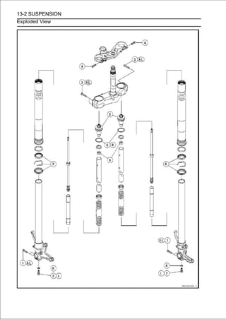
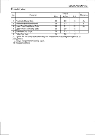
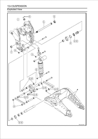
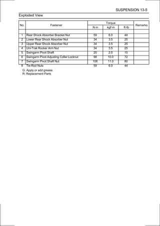
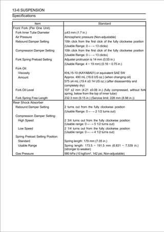
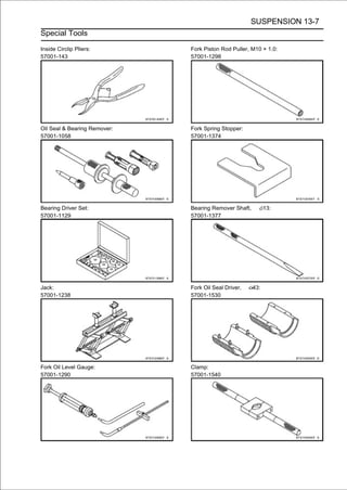
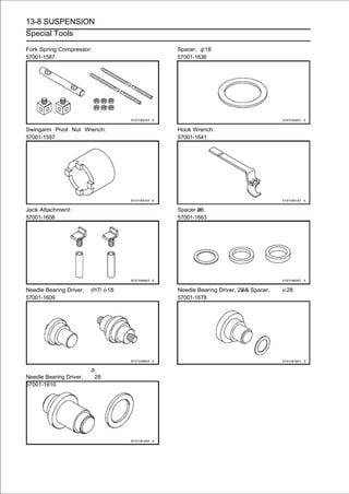
![SUSPENSION 13-9
Front Fork
Rebound Damping Force Adjustment
• To adjust the rebound damping force, turn the rebound
damping adjuster [A] until you feel a click.
○The standard adjuster setting for the average-build rider
of 68 kg (150 lb) with no passenger and no accessories
is the 10th click from the 1st click of the fully clockwise
position.
WARNING
If both adjusters are not adjusted equally, handling
may be impaired and a hazardous condition may
result.
○The damping force can be left soft for average riding. But
it should be adjusted harder for high speed riding or riding
with a passenger. If the damping feels too soft or too stiff,
adjust it in accordance with the following table.
Rebound Damping Force Adjustment
Adjuster Damping
Position Force Setting Load Road Speed
13 Weak Soft Light Good Low
↑ ↑ ↑ ↑ ↑ ↑
↓ ↓ ↓ ↓ ↓ ↓
0 Strong Hard Heavy Bad High
Compression Damping Force Adjustment
• To adjust the compression damping force, turn the
compression damping adjuster [A] until you feel a click.
○The standard adjuster setting for the average-build rider
of 68 kg (150 lb) with no passenger and no accessories
is the 10th click from the 1st click of the fully clockwise
position.
WARNING
If both adjusters are not adjusted equally, handling
may be impaired and a hazardous condition may
result.
○The damping force can be left soft for average riding. But
it should be adjusted harder for high speed riding or riding
with a passenger. If the damping feels too soft or too stiff,
adjust it in accordance with the following table.
Compression Damping Force Adjustment
Adjuster Damping
Position Force Setting Load Road Speed
13 Weak Soft Light Good Low
↑ ↑ ↑ ↑ ↑ ↑
↓ ↓ ↓ ↓ ↓ ↓
0 Strong Hard Heavy Bad High](https://image.slidesharecdn.com/2008-100321201635-phpapp01/85/2008-486-320.jpg)
![13-10 SUSPENSION
Front Fork
Spring Preload Adjustment
• Turn the spring preload adjuster [A] to change spring
preload setting.
○The standard adjuster setting for the average-build rider
of 68 kg (150 lb) with no passenger and no accessories
is the 14 mm (0.55 in.) [B] from the top plug nut surface
as shown in the figure.
Adjuster Protrusion (from the top plug nut surface)
Standard: 14 mm (0.55 in.)
Usable Range: 4∼19mm(0.16∼0.75in.)
WARNING
If both adjusters are not adjusted equally, handling
may be impaired and a hazardous condition may
result.
○The spring preload can be left soft for average riding. But
it should be adjusted harder for high speed riding or riding
with a passenger. If the spring action feels too soft or too
stiff, adjust it in accordance with the following table.
Spring Action
Adjuster Damping
Position Force Setting Load Road Speed
19 mm Weak Soft Light Good Low
↑ ↑ ↑ ↑ ↑ ↑
↓ ↓ ↓ ↓ ↓ ↓
4 mm Strong Hard Heavy Bad High
Front Fork Removal (Each Fork Leg)
• Remove:
Front Wheel (see Front Wheel Removal in the
Wheels/Tires chapter)
Front Fender (see Front Fender Removal in the Frame
chapter)
Upper Inner Fairing (see Upper Inner Fairing Removal in
the Frame chapter)
Loosen the front fork top plug [A] beforehand if the fork
leg is to be disassembled.
NOTE
○Loosen the top plug after loosening the handlebar
clamp bolt [B] and upper front fork clamp bolt [C].
• Loosen:
Handlebar Clamp Bolt [A]
Upper Front Fork Clamp Bolt [B]](https://image.slidesharecdn.com/2008-100321201635-phpapp01/85/2008-487-320.jpg)
![SUSPENSION 13-11
Front Fork
• Loosen the lower front fork clamp bolts [A].
• With a twisting motion, work the fork leg down and out.
Front Fork Installation
• Install the fork leg so that the top [A] of the outer tube is
flush with the upper surface [B] of the steering stem head.
• Tighten the lower front fork clamp bolts and top plug.
Torque - Lower Front Fork Clamp Bolts: 30 N·m (3.1 kgf·m,
22 ft·lb)
Front Fork Top Plug: 23 N·m (2.3 kgf·m, 17 ft·lb)
NOTE
○Tighten the two lower front fork clamp bolts alternately
two times to ensure even tightening torque.
○Tighten the front fork top plug before tightening the han-
dlebar clamp bolt and upper front fork clamp bolt.
• Tighten the upper front fork clamp bolt and handlebar
clamp bolt.
Torque - Upper Front Fork Clamp Bolt: 20 N·m (2.0 kgf·m,
15 ft·lb)
Handlebar Clamp Bolt: 25 N·m (2.5 kgf·m, 18 ft·lb)
• Install the removed parts (see appropriate chapters).
• Adjust:
Spring Preload (see Spring Preload Adjustment)
Rebound Damping Force (see Rebound Damping Force
Adjustment)
Compression Damping Force (see Compression Damping
Force Adjustment)
Front Fork Oil Change
• Remove the front fork (see Front Fork Removal (Each
Fork Leg)).
• Hold the inner tube lower end in a vise.
• Unscrew the top plug [A] out of the outer tube.](https://image.slidesharecdn.com/2008-100321201635-phpapp01/85/2008-488-320.jpg)
![13-12 SUSPENSION
Front Fork
• Install the clamps [A] as shown in the figure.
NOTE
○Set the clamps so that the cutouts [B] do not touch the
stoppers [C] of the top plug, pull up the outer tube [D]
to hold it by the clamps, and then tighten the two bolts
[E]. The outer tube is used as a guide.
Special Tools - Clamp: 57001-1540
Fork Spring Compressor: 57001-1587
• Insert the holder bar [A] into the axle hole of the front fork
[B].
• Set thethe compression shaft [A] andsame process. [B].
○
Insert
other side compression shaft
install the nut
• Insert of thelower end of the compression shaft [A] into the
hole [B]
the
holder bar.](https://image.slidesharecdn.com/2008-100321201635-phpapp01/85/2008-489-320.jpg)
![SUSPENSION 13-13
Front Fork
• Screw the figure. nut [A] onto the compression shaft as
shown in
the adjust
20 mm (0.79 in.) [B]
• Screw the locknut [C].
• Hold upin one side nut [A] come out the the nut.rod nut [B].
○
Screw
the top plug [C] while screwing in
piston
• Insert the fork spring while holdingbetween the piston rod
nut [B] and the clamp [C]
stopper [A]
up the top plug [D].
Special Tool - Fork Spring Stopper: 57001-1374
• Holding the piston rod[C] from the wrenchrod. remove the
top plug [B] with damper
nut with a
piston
[A],
• Remove the rebound damping adjuster rod [A] from the
piston rod.](https://image.slidesharecdn.com/2008-100321201635-phpapp01/85/2008-490-320.jpg)
![13-14 SUSPENSION
Front Fork
• Remove:
Washer [A]
Collar [B] (with Spring Seat [C])
Fork Spring [D]
• Drain the fork oil into a suitable container.
○Using the fork piston rod puller [A], pump the piston rod
[B] up and down at least ten times to expel the oil from
the fork.
Special Tool - Fork Piston Rod Puller, M10 × 1.0: 57001
-1298
• Hold the fork tubeway down.press the outer tube [A] and
the piston rod all the
upright,
• Pour in the type and amount of fork oil specified.
Fork Oil
Viscosity:
KHL15-10 (KAYABA01) or equivalent SAE 5W
Amount (Per Side):
When changing oil:
Approx. 490 mL (16.6 US oz.)
After disassembly and completely dry:
575 ±4 mL (19.4 ±0.14 US oz.)
If necessary, measure the oil level as follows.
○Hold the inner tube vertically in a vise.
○Using the fork piston rod puller [A], move the piston rod [B]
up and down more than ten times in order to expel all the air
from the fork oil.
Special Tool - Fork Piston Rod Puller, M10 × 1.0: 57001
-1298](https://image.slidesharecdn.com/2008-100321201635-phpapp01/85/2008-491-320.jpg)
![SUSPENSION 13-15
Front Fork
○Remove the fork piston rod puller.
○Wait until the oil level settles.
○With the fork fully compressed and the piston rod fully
pushed in, insert a tape measure or rod into the inner
tube, and measure the distance from the top of the inner
tube to the oil.
Oil Level (fully compressed, without spring)
Standard: 107 ±2 mm (4.21 ±0.08 in.)
NOTE
○Fork oil level may also be measured using the fork oil
level gauge.
Special Tool - Fork Oil Level Gauge [A]: 57001-1290
○With the fork fully compressed and without fork spring,
insert the gauge tube into the inner tube [B] and position
the stopper across the top end [C] of the inner tube.
Outer Tube [D]
○Set the gauge stopper [E] so that its lower side shows the oil
level distance specified [F].
○Pull the handle slowly to pump out the excess oil until the oil
no longer comes out.
If no oil is pumped out, there is insufficient oil in the inner
tube. Pour in enough oil, then pump out the excess oil as
shown above.
• Screw the fork piston rod puller onto the end of the piston
rod.
Special Tool - Fork Piston Rod Puller, M10 × 1.0: 57001
-1298
• Pull the puller up above the outer tube top.
• Install the fork spring [A] with the smaller end facing [B]
upward.
• Install the collar [A] so that the spring seat [B] faces down-
ward.
• Install the washer on the collar.](https://image.slidesharecdn.com/2008-100321201635-phpapp01/85/2008-492-320.jpg)
![13-16 SUSPENSION
Front Fork
• Install the clamps [A] as shown in the figure.
Special Tools - Clamp: 57001-1540
Fork Spring Compressor: 57001-1587
NOTE
○Set the clamps so that the cutouts [B] do not fit the hole
[C] of the washer [D], pull up the outer tube [E] to hold
it by the clamps, and then tighten the two bolts [F]. The
outer tube is used as a guide.
• Set the holder bar [A] and compression shafts [B].
• Screw in the fork compressor nut come out the piston rod
nut.
○Hold up the fork piston rod puller while screwing in the
nut.
• Insert thethe clamp [C]stopper [A] between fork piston rod
nut [B] and
fork spring
while holding up the
the piston
rod puller [D].
Special Tool - Fork Spring Stopper: 57001-1374
• Remove the fork piston rod puller.
• Install the rebound damping adjuster rod [A].](https://image.slidesharecdn.com/2008-100321201635-phpapp01/85/2008-493-320.jpg)
![SUSPENSION 13-17
Front Fork
• Screw the figure. rod nut [A] onto the piston rod [B] as
shown in
the piston
12 mm (0.47 in.) or more [C]
• Checkand rebound damping adjuster [B] with a pair of the
top plug
the distance between the bottom end [A] of
vernier caliper.
13 mm (0.51 in.) [C]
• Install the damper [A] on the top plug [B].
• Check ifthe O-ring [C] on the top plug and replace it with a
new one damaged.
○Apply grease to the new O-ring.
• Screw in the top plug stopped onto the piston rod.
• Holding the top top plug. a wrench, tighten the piston rod
nut [D] against the
plug with
Torque - Piston Rod Nuts: 15 N·m (1.5 kgf·m, 11 ft·lb)
• Remove the fork spring stopper.
• Align the stoppersand loosen top fork spring compres-
[C] of the clamp [D],
[A] of the
the
plug [B] with the grooves
sor nut.
• Remove the clamp and fork spring compressor.
• Raise the outer tube and screw the top plug into it.
• Install the front fork (see Front Fork Installation).
NOTE
○After installing the front fork, adjust the spring preload
and damping force correctly.
Front Fork Disassembly
• Remove the front fork (see Front Fork Removal (Each
Fork Leg)).
• Drain the fork oil (see Front Fork Oil Change).
• Hold the fork leg with a vise [A].
• Unscrew the Allen bolt [B], then take the bolt and gasket
out of the bottom of the inner tube.
If the cylinder unit is turned, loosen the Allen bolt while
pushing the piston rod using the fork piston rod puller.
Special Tool - Fork Piston Rod Puller, M10 × 1.0: 57001
-1298](https://image.slidesharecdn.com/2008-100321201635-phpapp01/85/2008-494-320.jpg)
![13-18 SUSPENSION
Front Fork
• Take the cylinder unit [A]cylinderthe inner tube.
○Do not disassemble the
out of
unit.
• Separate the outer tube [A] from the inner tube [B].
• Pull out the dust seal [C] from the outer tube.
• Remove the following parts from the outer tube.
Retaining Ring [A]
Oil Seal [B]
Washer [C]
Front Fork Assembly
• Replace the following parts with new ones.
Dust Seal
Oil Seal
Retaining Ring
Bottom Allen Bolt Gasket
• Insert the cylinder unit [A] into the inner tube [B].
• Applyit.a non-permanent locking agent to the Allen bolt and
tighten
Non-permanent Locking Agent - Three Bond: TB1342
Torque - Front Fork Bottom Allen Bolts: 23 N·m (2.3 kgf·m,
17 ft·lb)
If the cylinder unit is turned, tighten the Allen bolt while
pushing the piston rod using the fork piston rod puller.
Special Tool - Fork Piston Rod Puller, M10 × 1.0: 57001
-1298](https://image.slidesharecdn.com/2008-100321201635-phpapp01/85/2008-495-320.jpg)
![SUSPENSION 13-19
Front Fork
• Install Seal following parts into the inner tube [A].
Dust
the
[B]
Retaining Ring [C]
Oil Seal [D]
Washer [E]
• Insert the inner tube to the outer tube.
• After oil seal driver washer, install the oil seal [A] by using
the fork
installing the
[B].
Special Tool - Fork Oil Seal Driver, 43: 57001-1530
• Install the retaining ring and dust seal.
• Pour in the specified type of oil (see Front Fork Oil
Change).
Inner Tube Inspection
• Visually inspect the inner tube [A], and repair any dam-
age.
• Nick or rust damage can sometimes be repaired by using
a wet-stone to remove sharp edges or raised areas which
cause seal damage.
If the damage is not repairable, replace the inner tube.
Since damage to the inner tube damages the oil seal,
replace the oil seal whenever the inner tube is repaired
or replaced.
CAUTION
If the inner tube is badly bent or creased, replace it.
Excessive bending, followed by subsequent
straightening, can weaken the inner tube.
• Temporarily[C] them back and forth manually to outer tube
[B], and pump
assemble the inner tube [A] and
check
for smooth operation.
If you feel binding or catching, the inner and outer tubes
must be replaced.
WARNING
A straightened inner or outer fork tube may fall in
use, possibly causing an accident. Replace a badly
bent or damaged inner or outer tube and inspect the
other tube carefully before reusing it.](https://image.slidesharecdn.com/2008-100321201635-phpapp01/85/2008-496-320.jpg)
![13-20 SUSPENSION
Front Fork
Dust Seal Inspection
• Inspect the dust seals [A] for any signs of deterioration or
damage.
Replace it if necessary.
Spring Tension
• Since a spring becomes shorter as it weakens, check its
free length [A] to determine its condition.
If the spring of either fork leg is shorter than the service
limit, it must be replaced. If the length of a replacement
spring and that of the remaining spring vary greatly, the
remaining spring should also be replaced in order to keep
the fork legs balanced for motorcycle stability.
Spring Free Length
Standard: 232.3 mm (9.15 in.)
Service Limit: 228 mm (8.98 in.)](https://image.slidesharecdn.com/2008-100321201635-phpapp01/85/2008-497-320.jpg)
![SUSPENSION 13-21
Rear Shock Absorber
Rebound Damping Force Adjustment
• To adjust the rebound damping force, turn the rebound
damping adjuster [A] to the desired position.
○The standard adjuster setting for an average-build rider of
68 kg (150 lb) with no passenger and no accessories is the 2
turns out from the fully clockwise position.
Rebound Damping Force Adjustment
Adjuster Damping
Position Force Setting Load Road Speed
2 1/2 Turns
Out Weak Soft Light Good Low
↑ ↑ ↑ ↑ ↑ ↑
↓ ↓ ↓ ↓ ↓ ↓
0 Strong Hard Heavy Bad High
Compression Damping Force Adjustment
○There are two adjustments you can make to the compression
damping force.
High Speed Compression Damping Adjuster [A]
Low Speed Compression Damping Adjuster [B]
• To adjustdamping adjuster compression dampingtoforce, turn
the outside
the high speed
with a 14 mm wrench the
desired position.
○The standard adjuster setting for the average-build rider
of 68 kg (150 lb) with no passenger and no accessories
is the 2 3/4 turns out from the fully clockwise position.
High Speed Compression Damping Force Adjustment
Adjuster Damping
Position Force Setting Load Road
5 1/2 Turns
Out Weak Soft Light Good
↑ ↑ ↑ ↑ ↑
↓ ↓ ↓ ↓ ↓
0 Strong Hard Heavy Bad
NOTE
○When turning the high speed compression damping
force adjuster (outside), turn the low speed compres-
sion damping force adjuster (inside) too. But, the low
speed compression damping force (setting position)
dose not change.](https://image.slidesharecdn.com/2008-100321201635-phpapp01/85/2008-498-320.jpg)
![13-22 SUSPENSION
Rear Shock Absorber
• To adjust the low speed with a flat-head screwdriver turn
the inside damping adjuster
compression damping force,
to the desired position.
○The standard adjuster setting for the average-build rider
of 68 kg (150 lb) with no passenger and no accessories
is the 2 1/4 turns out from the fully clockwise position.
Low Speed Damping Force Adjustment
Adjuster Damping
Position Force Setting Load Road
4 1/2 Turns
Out Weak Soft Light Good
↑ ↑ ↑ ↑ ↑
↓ ↓ ↓ ↓ ↓
0 Strong Hard Heavy Bad
Spring Preload Adjustment
• Loosen the locknut and turn out the adjusting nut to free
the spring.
Special Tool - Hook Wrench: 57001-1641
• To adjust position and tighten turnlocknutadjusting nut [A] to
the desired
the spring preload,
the
in the
[B].
Spring Length [C]
○The standard adjusting nut setting for an average-build
rider of 68 kg (150 lb) with no passenger and no
accessories is 179 mm (7.05 in.) spring length.
Spring Preload Setting
Standard: Spring length 179 mm (7.05 in.)
Usable Range: Spring length 173.5 ∼ 191.5 mm (6.831
∼ 7.539 in.)
• Remove the bolts [A] and foot guard [B] for turning the
hook wrench easily.](https://image.slidesharecdn.com/2008-100321201635-phpapp01/85/2008-499-320.jpg)
![SUSPENSION 13-23
Rear Shock Absorber
• To adjustposition and tighten the locknut using by hook to
the desired
the spring preload, turn in the adjusting nut
wrenches [A] with the rear shock absorber attached the
frame.
Special Tool - Hook Wench: 57001-1641
If the spring action feels too soft or too stiff, adjust it.
Spring Adjustment
Adjuster Damping
Position Force Setting Load Road Speed
191.5 mm
(7.539 in.) Weak Soft Light Good Low
↑ ↑ ↑ ↑ ↑ ↑
↓ ↓ ↓ ↓ ↓ ↓
173.5 mm
(6.831 in.) Strong Hard Heavy Bad High
Rear Shock Absorber Removal
• Remove:
Lower Fairings (see Lower Fairing Removal in the Frame
chapter)
Premuffler Chamber (see Premuffler Chamber Removal in
the Engine Top End chapter)
• Squeeze the brake lever slowly and hold it with a band
[A].
WARNING
Be sure to hold the front brake when removing the
shock absorber, or the motorcycle may fall over. It
could cause an accident and injury.
• Using the jack, raise the rear wheel off the ground.
Special Tools - Jack: 57001-1238
Jack Attachment: 57001-1608
• Remove:
Lower Rear Shock Absorber Bolt and Nut [A]
Upper Tie-Rod Bolt and Nut [B]
Upper Rear Shock Absorber Bolt and Nut [C]
• Remove the rear shock absorber downward while lifting up
the rear wheel.
Rear Shock Absorber Installation
•Tighten:
Torque - Rear Shock Absorber Nuts (Upper and Lower): 34
N·m (3.5 kgf·m, 25 ft·lb)
Tie-Rod Nuts: 59 N·m (6.0 kgf·m, 44 ft·lb)](https://image.slidesharecdn.com/2008-100321201635-phpapp01/85/2008-500-320.jpg)
![13-24 SUSPENSION
Rear Shock Absorber
Rear Shock Absorber Inspection
• Remove the rear shock absorber (see Rear Shock
Absorber Removal).
•Visually inspect the following items.
Smooth Stroke
Oil Leakage
Crack or Dent
If there is any damage to the rear shock absorber, replace
it.
•Visually inspect the rubber bushing [A].
If it show any signs of damage, replace it.
Rear Shock Absorber Scrapping
WARNING
Since the reservoir tank of the rear shock absorber
contains nitrogen gas, do not incinerate the reser-
voir tank without first releasing the gas or it may
explode.
• Remove the rear shock absorber. (see Rear Shock
Absorber Removal).
• Drillin.) drillbit. [A] of the reservoir tank using about 2 mm
(0.08
the hole
WARNING
Wear safety glasses when drilling the hole, as the
high pressure gas may blow out bits or drilled metal
when the hole opens.](https://image.slidesharecdn.com/2008-100321201635-phpapp01/85/2008-501-320.jpg)
![SUSPENSION 13-25
Swingarm
Swingarm Removal
•Remove:
Rear Wheel (see Rear Wheel Removal in the
Wheels/Tires chapter)
Chain Cover (see Drive Chain Removal in the Final Drive
chapter)
Engine Sprocket Cover (see Engine Sprocket Removal in
the Final Drive chapter)
Mud Guard (see Mad Guard Removal in the Frame
chapter)
Rear Shock Absorber (see Rear Shock Absorber Re-
moval)
•Disengage the drive chain from the engine sprocket.
•Unscrew the swingarm pivot shaft nut [A].
• Using the swingarm collar locknut [B]. [A], loosen the
swingarm pivot adjusting
pivot nut wrench
Special Tool - Swingarm Pivot Nut Wrench: 57001-1597
• Turn the swingarmthe swingarm. counterclockwise to free the
adjusting collar from
pivot shaft [A]
○Make the gap between the adjusting collar and swingarm.
• Pull out the pivot shaft to the right side and remove the
swingarm.
Swingarm Installation
• Visually inspect the chain guide [A].
Replace the chain guide if it shows any signs of abnormal
wear or damage.
○Apply a non-permanent locking agent to the threads of
the chain guide bolt.](https://image.slidesharecdn.com/2008-100321201635-phpapp01/85/2008-502-320.jpg)
![13-26 SUSPENSION
Swingarm
• Apply grease to the lips of the grease seals [A].
• Be sure to install the grease seals and sleeve [B] to the
swingarm.
• Fit the collar [C] on the grease seal of the left side.
• Install the the figure. pivot adjusting collar [A] on the frame [B]
as shown in
swingarm
11 mm (0.43 in.) [C]
• Insert the swingarm pivot shaft [A] intoshaft.adjusting collar [B]
from the right side, and tighten the pivot
the
NOTE
○Tighten the swingarm pivot shaft until the clearance [C]
between the ball bearing [D] and collar come to 0 mm
(0 in.).
Torque - Swingarm Pivot Shaft: 20 N·m (2.0 kgf·m, 15 ft·lb)
• Using the swingarmcollar locknut [E].
swingarm pivot adjusting
pivot nut wrench, tighten the
Special Tool - Swingarm Pivot Nut Wrench: 57001-1597
Torque - Swingarm Pivot Adjusting Collar Locknut: 98 N·m
(10.0 kgf·m, 72 ft·lb)
• Tighten the swingarm pivot shaft nut.
Torque - Swingarm Pivot Shaft Nut: 108 N·m (11.0 kgf·m,
80 ft·lb)
• Move the swingarm up and down to check for abnormal
friction.
• Install the removed parts (see appropriate chapters).
Swingarm Bearing Removal
•Remove:
Swingarm (see Swingarm Removal)
Collar [A]
Grease Seals [B]
Sleeve [C]
Circlip (Right Side) [D]
Special Tool - Inside Circlip Pliers: 57001-143](https://image.slidesharecdn.com/2008-100321201635-phpapp01/85/2008-503-320.jpg)
![SUSPENSION 13-27
Swingarm
• Remove the ball bearing and needle bearings.
Special Tool - Oil Seal & Bearing Remover [A]: 57001-1058
Swingarm Bearing Installation
• Replace the needle bearings, ball bearing, grease seals
and circlip with new ones.
• Install the needle bearings, ball bearing, grease seals and
circlip as shown in the figure.
○Insert the needle bearing driver [A] into the needle bearing [B]
and press the needle bearing into the housing until the driver
contacts the end surface of the housing.
Bearing Pressing Depth: 27.5 mm (1.08 in.) [C]
32 mm (1.25 in.) [D]
NOTE
○For a bearing of the left side, select the pressing side
of the needle bearing driver according to its pressing
depth.
○When pressing in the needle bearings of the left side,
adjust the pressing depth with the spacer [E].
○Install the needle bearings so that the marked side
faces out.
Special Tools - Bearing Driver Set: 57001-1129
Needle Bearing Driver, 28: 57001-1610
Spacer 28: 57001-1663
Needle Bearing Driver, 20 & Spacer, 28
(Spacer): 57001-1678
○Press in the ball bearing until it bottomed.
Special Tool - Bearing Driver Set: 57001-1129
○Install the circlip.
Special Tool - Inside Circlip Pliers: 57001-143
○Press in the grease seals so that seal surface is flushed
with the end of housing.
Special Tool - Bearing Driver Set: 57001-1129](https://image.slidesharecdn.com/2008-100321201635-phpapp01/85/2008-504-320.jpg)
![13-28 SUSPENSION
Swingarm
32 mm (1.26 in.) [A]
17 mm (0.67 in.) [B]
1 mm (0.04 in.) [C]
1.5 mm (0.06 in.) [D]
9.5 mm (0.37 in.) [E]
27.5 mm (1.08 in.) [F]
Needle Bearings [G]
Grease Seals [H]
Ball Bearing [I]
Circlip [J]
Swingarm Bearing, Sleeve Inspection
CAUTION
Do not remove the bearings for inspection.
Removal may damage them.
• Inspect the needle bearings [A] and ball bearing installed in
the swingarm.
○The rollers and ball in a bearing normally wear very little,
and wear is difficult to measure. Instead of measuring,
visually inspect the bearing for abrasion, discoloration, or
other damage.
If the needle bearing, and sleeve [B] show any sings of
abnormal wear, discoloration, or damage, replace them
as a set.](https://image.slidesharecdn.com/2008-100321201635-phpapp01/85/2008-505-320.jpg)
![SUSPENSION 13-29
Swingarm
• Turn the ballfor plays, roughness, or binding. and forth [A]
while checking
bearing in the swingarm back
If bearing play, roughness, or binding is found, replace
the bearing.
• Examine the bearing seal [B] for tears or leakage.
If the seal is torn or is leaking, replace the bearing.
Swingarm Bearing Lubrication
NOTE
○Since the bearing are packed with grease and sealed,
lubrication is not required.](https://image.slidesharecdn.com/2008-100321201635-phpapp01/85/2008-506-320.jpg)
![13-30 SUSPENSION
Tie-Rod, Rocker Arm
Tie-Rod Removal
• Remove:
Lower Fairings (see Lower Fairing Removal in the Frame
chapter)
Premuffler Chamber (see Premuffler Chamber Removal in
the Engine Top End chapter)
• Squeeze the brake lever slowly and hold it with a band
[A].
WARNING
Be sure to hold the brake lever when removing the
tie-rod, or the motorcycle may fall over. If could
cause an accident and injury.
• Using the jack, raise the rear wheel off the ground.
Special Tools - Jack: 57001-1238
Jack Attachment: 57001-1608
• Remove:
Upper Tie-Rod Bolt and Nut [A]
Lower Tie-Rod Bolt and Nut [B]
Tie-Rods [C]
Tie-Rod Installation
• Install the tie-rods so that the marked side [A] faces out-
ward.
• Tighten:
Torque - Tie-Rod Nuts: 59 N·m (6.0 kgf·m, 44 ft·lb)
Rocker Arm Removal
• Remove:
Lower Fairings (see Lower Fairing Removal in the Frame
chapter)
Premuffler Chamber (see Premuffler Chamber Removal in
the Engine Top End chapter)
• Squeeze the brake lever slowly and hold it with a band
[A].
WARNING
Be sure to hold the brake lever when removing the
rocker arm, or the motorcycle may fall over. If could
cause an accident and injury.
• Using the jack, raise the rear wheel off the ground.
Special Tools - Jack: 57001-1238
Jack Attachment: 57001-1608](https://image.slidesharecdn.com/2008-100321201635-phpapp01/85/2008-507-320.jpg)
![SUSPENSION 13-31
Tie-Rod, Rocker Arm
• Remove:
Lower Rear Shock Absorber Bolt and Nut [A]
Lower Tie-Rod Bolt and Nut [B]
Rocker Arm Bolt and Nut [C]
Rocker Arm [D]
Rocker Arm Installation
• Apply grease to the lips of the grease seals [A].
• Be sure to install the grease seals and sleeves [B] to the
rocker arm.
• Tighten:
Torque - Uni-Trak Rocker Arm Nut: 34 N·m (3.5 kgf·m, 25
ft·lb)
Tie-Rod Nuts: 59 N·m (6.0 kgf·m, 44 ft·lb)
Rear Shock Absorber Nuts: 34 N·m (3.5 kgf·m, 25
ft·lb)
Tie-Rod and Rocker Arm Bearing Removal
• Remove:
Tie-Rods (see Tie-Rod Removal)
Rocker Arm (see Rocker Arm Removal)
Sleeves [A]
Grease Seals [B]
Swingarm [C]
Needle Bearings [D]](https://image.slidesharecdn.com/2008-100321201635-phpapp01/85/2008-508-320.jpg)
![13-32 SUSPENSION
Tie-Rod, Rocker Arm
○When removing the needle bearings [A], tap the bearings
evenly with the bearing remover shaft [B].
Special Tool - Bearing Remover Shaft, 13: 57001-1377
Tie-Rod and Rocker Arm Bearing Installation
• Replace the needle bearings and grease seals with new
ones.
• Install the needle bearings and grease seals position as
shown in the figure.
○Screw the needle bearing driver [A] into the driver holder
[B].
○Insert the needle bearing [C] driver into the needle bearing
and press the needle bearing into the housing until the
driver contacts the end surface of the housing.
Bearing Pressing Depth: 5.5 mm (0.22 in.) [D]
5.0 mm (0.20 in.) [E]
NOTE
○For a bearing of inside diameter 18, select the press-
ing side of the needle bearing driver according to its
pressing depth.
○When pressing in the needle bearings to the 5.5 mm
(0.22 in.) depth, adjust the pressing depth with the
spacer [F].
○Install the needle bearings so that the marked side
faces out.
Special Tools - Bearing Driver Set: 57001-1129
Needle Bearing Driver, 17/ 18: 57001
-1609
Spacer, 18: 57001-1636](https://image.slidesharecdn.com/2008-100321201635-phpapp01/85/2008-509-320.jpg)
![SUSPENSION 13-33
Tie-Rod, Rocker Arm
7.5 mm (0.30 in.) [A]
5.0 mm (0.20 in.) [B]
5.5 mm (0.22 in.) [C]
Needle Bearings [D]
Grease Seals [E]
Rear Shock Absorber [F]
Tie-Rod [G]
Rocker Arm [H]
Front [I]
Right Side [J]
Left Side [K]
Tie-Rod/Rocker Arm Bearing, Sleeve Inspection
CAUTION
Do not remove the bearings for inspection.
Removal may damage them.
• Visually inspect the rocker arm, or tie-rod sleeves [A] and
needle bearings [B].
• The rollers in a needle bearing normallymeasuring, little,
and wear is difficult to measure. Instead of
wear very
inspect the bearing for abrasion, color change, or other
damage.
If there is any doubt as to the condition of any of the needle
bearings or sleeves, replace the sleeves and needle
bearings as a set.
Tie-Rod/Rocker Arm Bearing Lubrication
NOTE
○Since the bearings are packed with grease, lubrication is
not required.](https://image.slidesharecdn.com/2008-100321201635-phpapp01/85/2008-510-320.jpg)

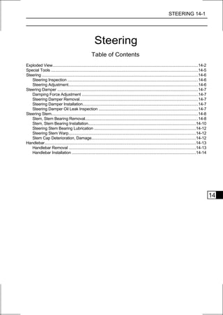
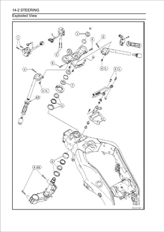
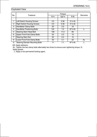
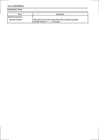
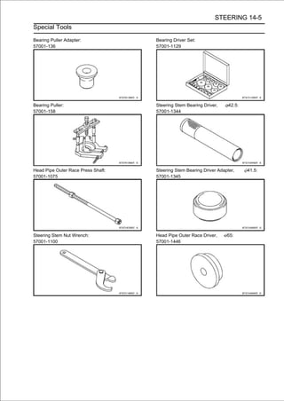
![STEERING 14-7
Steering Damper
Damping Force Adjustment
• To adjust the damping force, turn the damping adjuster
[A] until you feel a click.
○The standard adjuster setting is the 18th click from the
1st of the fully clockwise position. If the damping feels too
soft or too stiff, adjust it in accordance with the following
table.
Damping Force Adjustment
Adjuster Position Damping Force Setting
18 Weak Soft
↑ ↑ ↑
↓ ↓ ↓
0 Strong Hard
Steering Damper Removal
• Remove:
Steering Damper Mounting Bolts (TORX Bolts) [A]
Washer [B]
Washer and Collar [C]
Steering Damper [D]
Steering Damper Installation
• Install the following parts as shown in the figure.
Collar [A]
Washers [B]
Steering Damper [C]
• Apply a non-permanent locking agent to the threads of
the steering damper mounting bolts (TORX bolts) [D].
• Tighten:
Torque - Steering Damper Mounting Bolts: 11 N·m (1.1
kgf·m, 97 in·lb)
• After tightening[A] insteering damper mounting bolts, confirm
that there is play
the
the steering damper [B].
Left Side View [C]
Steering Damper Oil Leak Inspection
• Refer to the Steering Damper Oil Leak Inspection in the
Periodic Maintenance chapter.](https://image.slidesharecdn.com/2008-100321201635-phpapp01/85/2008-518-320.jpg)
![14-8 STEERING
Steering Stem
Stem, Stem Bearing Removal
• Remove:
Steering Damper (see Steering Damper Removal)
Clutch Lever Assembly [A]
Left Switch Housing [B]
• Remove:
Front Master Cylinder [A] (see Front Master Cylinder Re-
moval in the Brakes chapter)
Right Switch Housing [B]
Throttle Case [C]
• Loosen:
Upper Front Fork Clamp Bolt [A] (Both Sides)
Handlebar Clamp Bolt [B] (Both Sides)
• Remove:
Plug [A]
Steering Stem Head Bolt [B] and Washer
Steering Stem Head [C] with Handlebars [D]
Front Forks (see Front Fork Removal (Each Fork Leg) in
the Suspension chapter)
• Remove the brake hose fitting bolt [A].](https://image.slidesharecdn.com/2008-100321201635-phpapp01/85/2008-519-320.jpg)
![STEERING 14-9
Steering Stem
• Straighten the claws [A] of the lock washer [B].
• Remove:
Steering Stem Locknut [C]
Lock Washer
• Pushing upcap [B]. base, and remove the steering stem nut
[A] with stem
the stem
Special Tool - Steering Stem Nut Wrench [C]: 57001-1100
• Remove the steering stem [D] under side.
• Remove the upper bearing inner race [A] and bearing [B].
• To pipe [B], insertbearing outerthe recesses [D] of head the
head
remove the
a bar [C] into
races [A] pressed into
pipe, and applying it to both recess alternately hammer it to
drive the race out.
NOTE
○If either steering stem bearing is damaged, it is recom-
mended that both the upper and lower bearings (includ-
ing outer races) should be replaced with new ones.
• Remove the bearing [A] from the steering stem.](https://image.slidesharecdn.com/2008-100321201635-phpapp01/85/2008-520-320.jpg)
![14-10 STEERING
Steering Stem
• Remove the loweronto the steeringrace (withwithgrease seal)
[A] which is pressed
bearing inner
stem [B]
its
the
bearing puller [C], adapter [D] and suitable tool [E].
○Install the suitable tool between the steering stem and
adapter.
Special Tools - Bearing Puller Adapter: 57001-136
Bearing Puller: 57001-158
Stem, Stem Bearing Installation
• Replace the bearing outer races with new ones.
• Drive them into the head pipe at the same time.
Special Tools - Head Pipe Outer Race Press Shaft [A]:
57001-1075
Bearing Driver Set: 57001-1129
Head Pipe Outer Race Driver, 55 [B]: 57001
-1446
• Apply grease to the outer races.
• Replace the bearing inner races [A] and grease seal [B]
with new ones.
• Install the greaserace applied the greasestem,the stem. the
lower bearing inner
seal on the steering
onto
and drive
○The upper and lower inner races are identical.
Special Tools - Steering Stem Bearing Driver, 42.5 [C]:
57001-1344
Steering Stem Bearing Driver Adapter,
41.5 [D]: 57001-1345
• Apply grease to the lower bearing [A], and install it onto
the steering stem.
○The upper and lower bearings are identical.
• Apply grease to the upper bearing [B] and inner race [C].
• Install the steering stemand inner racethe head pipe and
install the upper bearing [B]
[A] through
[C] on it.
• Install the stem cap [D] and steering stem nut [E].](https://image.slidesharecdn.com/2008-100321201635-phpapp01/85/2008-521-320.jpg)
![STEERING 14-11
Steering Stem
• Settle the inner races in place as follows.
○Tighten the steering stem nut with 55 N·m (5.6 kgf·m, 41
ft·lb) of torque first, and loosen it a fraction of a turn until
it turns lightly. Afterward tighten it again with specified
torque using a stem nut wrench [A] in the direction shown.
○Check that there is no play and the steering stem turns
smoothly without rattles. If not, the steering stem bearings may
be damaged.
Special Tool - Steering Stem Nut Wrench: 57001-1100
Torque - Steering Stem Nut: 20 N·m (2.0 kgf·m, 15 ft·lb)
• Install the lock washer [A] so that its bent side [B] faces
upward, and engage the bent claws with the grooves of
the steering stem locknut [C].
• Tighten the stem locknut by hand until the lock washer
touches the steering stem nut [D].
• Tighten the stem (rangingagain 2nd to 4th) of the stem nut,
with the grooves
locknut
from
until the claws are aligned
and bend the two claws downward [E].
• Install the steering stem head [F].
• Install the washer [G], and tighten the steering stem head
bolt [H] temporarily.
• Suspensionfront forks (see Front Fork Installation in the
Install the
chapter).
NOTE
○Tighten the upper front fork clamp bolts first, next the
steering stem head bolt, last the lower front fork clamp
bolts and handlebar clamp bolts.
○Tighten the two lower front fork clamp bolts alternately
two times to ensure even tightening torque.
Torque - Upper Front Fork Clamp Bolts 20 N·m (2.0 kgf·m,
15 ft·lb)
Steering Stem Head Bolt: 108 N·m (11.0 kgf·m, 80
ft·lb)
Lower Front Fork Clamp Bolts: 30 N·m (3.1 kgf·m,
22 ft·lb)
Handlebar Clamp Bolts: 25 N·m (2.5 kgf·m, 18
ft·lb)
WARNING
Do not impede the handlebar turning by routing the
cables, harness and hoses improperly (see Cable,
Wire, and Hose Routing section in the Appendix
chapter).
• Install the plug [I] on the steering stem head bolt.](https://image.slidesharecdn.com/2008-100321201635-phpapp01/85/2008-522-320.jpg)
![14-12 STEERING
Steering Stem
• Install the left and right switch housings.
○Fit the projection [A] into a small hole [B] in the handlebar.
Torque - Left and Right Switch Housing Screws: 3.5 N·m
(0.36 kgf·m, 31 in·lb)
• Install:
Front Master Cylinder (see Front Master Cylinder Instal-
lation in the Brakes chapter)
Clutch Lever Assembly (see Clutch Lever Installation in
the Clutch chapter)
Throttle Case (see Throttle Body Assy Installation in the
Fuel System (DFI) chapter
Steering Damper (see Steering Damper Installation)
Steering Stem Bearing Lubrication
• Refer to the Steering Stem Bearing Lubrication in the
Periodic Maintenance chapter.
Steering Stem Warp
• Whenever the steering stem is removed, or if the steering
can not be adjusted for smooth action, check the steering
stem for straightness.
If the steering stem [A] is bent, replace the steering stem.
Stem Cap Deterioration, Damage
Replace the stem cap if its grease seal [A] shows dam-
age.](https://image.slidesharecdn.com/2008-100321201635-phpapp01/85/2008-523-320.jpg)
![STEERING 14-13
Handlebar
Handlebar Removal
•Remove:
Steering Damper (see Steering Damper Removal)
Clutch Lever Assembly [A]
Left Switch Housing [B]
Left Handlebar Weight [C]
Left Handlebar Grip [D]
• Remove:
Front Master Cylinder [A] (see Front Master Cylinder Re-
moval in the Brakes chapter)
Right Switch Housing [B]
Throttle Case [C]
Left Handlebar Weight [D]
Throttle Grip [E]
• Loosen:
Upper Front Fork Clamp Bolt [A] (Both Sides)
Handlebar Clamp Bolt [B] (Both Sides)
• Remove:
Plug [A]
Steering Stem Head Bolt [B] and Washer
Steering Stem Head [C] with Handlebars [D]
• Remove:
Bolts [A]
Steering Damper Bracket [B]](https://image.slidesharecdn.com/2008-100321201635-phpapp01/85/2008-524-320.jpg)
![14-14 STEERING
Handlebar
• Remove:
Handlebar Positioning Bolts [A]
Handlebars [B]
Handlebar Installation
• Apply a non-permanent locking agent to the threads of
the handlebar positioning bolts and tighten them.
Torque - Handlebar Positioning Bolts: 9.8 N·m (1.0 kgf·m,
87 in·lb)
• Install the steering damper bracket.
• Install the washer [A] and steering stem head bolt [B].
• Tighten:
Torque - Steering Stem Head Bolt: 108 N·m (11.0 kgf·m, 80
ft·lb)
Upper Front Fork Clamp Bolts: 20 N·m (2.0 kgf·m,
15 ft·lb)
Handlebar Clamp Bolts: 25 N·m (2.5 kgf·m, 18
ft·lb)
NOTE
○Tighten the steering stem head bolt before tightening
the upper front fork clamp bolts and handlebar clamp
bolts.
WARNING
Do not impede the handlebar turning by routing the
cables, harness and hoses improperly (see Cable,
Wire, and Hose Routing section in the Appendix
chapter).
• Install the plug [C] on the steering stem head bolt.
• Apply adhesive cement to the inside of the left handlebar
grip.
• Install the handlebar weight securely.
• Install the left and right switch housings.
○Fit the projection [A] into a small hole [B] in the handlebar.
Torque - Left and Right Switch Housing Screws: 3.5 N·m
(0.36 kgf·m, 31 in·lb)](https://image.slidesharecdn.com/2008-100321201635-phpapp01/85/2008-525-320.jpg)


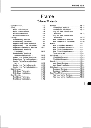
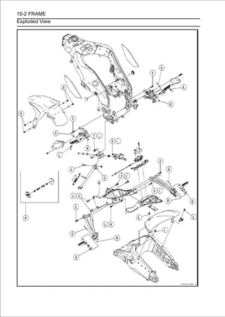
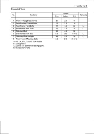
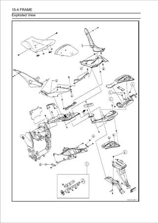

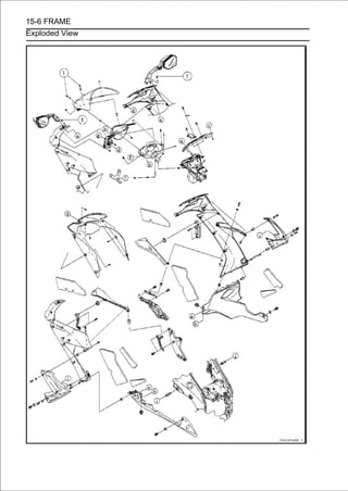
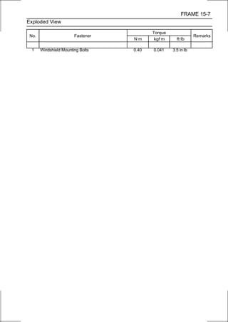
![15-8 FRAME
Seats
Front Seat Removal
• Remove:
Side Covers (see Side Cover Removal)
Bolts [A] (Both Sides)
• Remove the seat [B] forward while lifting up the front part of
the seat.
Front Seat Installation
• Installation is the reverse of removal, note the following.
○Slip the seat hook [A] under the rib [B] on the rear frame
front.
Rear Seat Removal
• Insert the ignition switch key [A] into the seat lock.
• Pull up the seat upward while turning the key clockwise,
and remove it forward.
Rear Seat Installation
• Slip the seat hook [A] under the rib [B] on the rear frame
rear.
• Insert the seat latches [C] into the latch holes [D].
• Push down the seat until the lock clicks.](https://image.slidesharecdn.com/2008-100321201635-phpapp01/85/2008-535-320.jpg)
![FRAME 15-9
Fairings
Lower Fairing Removal
• Remove:
Quick Rivets [A]
Bolts [B] with Washers (Both Sides)
○Pull up the core [C] by the flat-head screwdriver, and then
remove the quick rivet.
• Clear the hook portions [D] from the slots and remove the
right lower fairing [E].
• Remove the left lower fairing in the same way.
Lower Fairing Installation
• Installation is the reverse of removal, note the following.
○Insert the hook portions [A] into the slots [B].
○Hang the hook portion [C] inside the rib [D].
Upper Fairing Cover Removal
• Remove bolts [A] with washers.
• Clear the hook portions [B] from the slots and ribs (right
side only), and remove the upper fairing cover [C].
Upper Fairing Cover Installation
•Installation is the reverse of removal, note the following.
○Check that the pads [A] are in place on the upper fairing
cover.
Left Upper Fairing Cover [B]
Right Upper Fairing Cover [C]](https://image.slidesharecdn.com/2008-100321201635-phpapp01/85/2008-536-320.jpg)
![15-10 FRAME
Fairings
○For the right upper fairing cover, hang the lower hook
portions [A] inside the ribs [B] of the upper fairing, and then
insert the upper hook portions [C] into the slots [D].
○For the left upper fairing, insert the hook portions into the
slots of the upper fairing cover.
Upper Faring Assembly Removal
•Remove:
Lower Fairings (see Lower Fairing Removal)
Upper Fairing Covers (see Upper Fairing Cover Re-
moval)
Upper Inner Fairings (see Upper Inner Fairing Removal)
Meter Unit (see Meter Unit Removal in the Electrical System
chapter)
• For the California and Southeast Asia models, remove the
canister [A].
○Remove the band [B], and then remove the canister.
• For models equipped with an immobilizer system, remove the
immobilizer amplifier [A].
○Pull out the immobilizer amplifier with the rubber protector [B]
from the bracket [C].
• Open the clamps [A] on both sides and free the leads.
• Disconnect:
Headlight Connectors [B] (Both Sides)
City Light Lead Connectors [C] (Both Sides)](https://image.slidesharecdn.com/2008-100321201635-phpapp01/85/2008-537-320.jpg)
![FRAME 15-11
Fairings
• Open the clamps [A] and free the main harness.
• Open the clamp [A] and free the leads.
• Disconnect the turn signal light lead connectors [B].
• Remove the bolts [A] and clamp [B].
• Pull both upper fairing [A] outward to clear the projections
[B] on
the
sides.
• Remove the upper fairing assembly forward [C].
Upper Fairing Assembly Installation
•Installation is the reverse of removal, note the following.
○Run the harness and leads correctly (see Cable, Wire,
and Hose Routing section in the Appendix chapter).](https://image.slidesharecdn.com/2008-100321201635-phpapp01/85/2008-538-320.jpg)
![15-12 FRAME
Fairings
○Install the frame ground lead [A] and clamp [B] as shown in
the figure.
○Insert the projection [A] of the right upper fairing into the
grommet [B] on the bracket [C] of the starter clutch cover.
○Insert the projection of the left upper fairing into the grom-
met on the bracket of the alternator cover in the same
way.
Upper Fairing Assembly Disassembly/Assembly
•Remove:
Center Inner Fairing (see Center Inner Fairing Removal)
Nuts [A] and Rear View Mirrors
Bracket [B]
Screws [C]
•Separate the center fairing [D] and upper fairings.
○Clear the hook portions [E] from the slots.
• Assembly is the reverse of disassembly, note the follow-
ing.
○Check that the pads [A] are in place on the upper fairing.
Left Upper Fairing [B]
Right Upper Fairing [C]](https://image.slidesharecdn.com/2008-100321201635-phpapp01/85/2008-539-320.jpg)
![FRAME 15-13
Fairings
○Insert the hook portions [A] into the slots [B].
Upper Inner Fairing Removal
• Remove the bolt [A] with washer.
• Pull the upper inner fairing [B] inward to clear the projec-
tion [C].
• Remove the upper inner fairing backward while lifting up
the rear part.
Upper Inner Fairing Installation
• Installation is the reverse of removal, note the following.
○Insert the hook portion [A] into the slot [B] of the headlight.
○Insert the projection [A] of the upper fairing into the grommet
[B] on the upper inner fairing.
Center Fairing Removal/Installation
• Refer to the Upper Fairing Assembly Disassembly/As-
sembly.](https://image.slidesharecdn.com/2008-100321201635-phpapp01/85/2008-540-320.jpg)
![15-14 FRAME
Fairings
Center Inner Fairing Removal
•Remove:
Upper Fairing Assembly (see Upper Fairing Assembly
Removal)
Headlight (see Headlight Removal in the Electrical System
chapter)
Quick Rivets [A]
○Push the central pin, and then remove the quick rivet.
•Clear the hook portions [B].
• Remove the screw [A].
• Pull the centerthe slots, and remove it. to clear the hook
portions [C] from
inner fairing [B] backward
Center Inner Fairing Installation
•Installation is the reverse of removal, note the following.
○Insert the hook portions [A] of the front into the slots [B].
○Insert the hook portions [A] of the left and right into the
ribs [B].](https://image.slidesharecdn.com/2008-100321201635-phpapp01/85/2008-541-320.jpg)
![FRAME 15-15
Side Covers
Side Cover Removal
• Remove the bolt [A] with washer.
• Pull the side cover [B] evenly outward to clear the projection
[C] and hook fastener [D], and remove it.
Side Cover Installation
• Installation is the reverse of removal, note the following.
○Insert the projection [A] into the grommet [B] on the seat
cover, and then attach the hook fastener [C] to the hook
fastener [D] on the fuel tank.](https://image.slidesharecdn.com/2008-100321201635-phpapp01/85/2008-542-320.jpg)
![15-16 FRAME
Seat Covers
Seat Cover Removal
• Remove:
Seats (see Front/Rear Seat Removal)
Bolts [A]
• Pull the center seat cover [B] backward to clear the hook
portions [C], and remove it upward.
• Remove the quick rivets [A].
○Push the central pin, and then remove the quick rivet.
• Remove the bolts [A].
• Pull the[C] and hook portionsevenly outward to clear the
projection
left seat cover [B]
[D], and remove it.
• Remove the right seat cover in the same way.
Seat Cover Installation
• Installation is the reverse of removal, note the following.
○Insert the hook portions [A] into the slot [B] and ribs [C].
○Insert the projection [A] into the grommet [B] on the
bracket of the rear frame front.](https://image.slidesharecdn.com/2008-100321201635-phpapp01/85/2008-543-320.jpg)
![FRAME 15-17
Seat Covers
○Insert the hook portions [A] into the slots [B].](https://image.slidesharecdn.com/2008-100321201635-phpapp01/85/2008-544-320.jpg)
![15-18 FRAME
Fenders
Front Fender Removal
• Remove:
Clamps [A] (Both Sides)
Bolts [B] with Washers (Both Sides)
Reflectors [C] (Both Sides, US, CA, CAL, AU and SEA
Models)
Front Fender [D]
Front Fender Installation
• Tighten:
Torque - Front Fender Mounting Bolts: 3.9 N·m (0.40 kgf·m,
35 in·lb)
Flap and Rear Fender Rear Removal
• Remove:
Seat Covers (see Seat Cover Removal)
Owner’s Tool [A]
• Lift up the relay box [B] and the ECU together with rubber
protector [C].
○Do not disconnect the relay box connectors and ECU con-
nectors.
• Disconnect:
Tail/Brake Light Connector [A]
Turn Signal Light Lead Connectors [B]
License Plate Light Lead Connector [C]
Vehicle-down Sensor Connector [D]
Atmospheric Pressure Sensor Connector [E]
• Remove:
Bolt [A]
Seat Lock Cover [B]
○Clear the hook portion [C] from the slot.](https://image.slidesharecdn.com/2008-100321201635-phpapp01/85/2008-545-320.jpg)
![FRAME 15-19
Fenders
• Remove the lower end [A] of the seat lock cable [B].
• Open the clamp [A] and free the leads.
• Remove:
Bolt [B]
Rear Fender Rear Bracket Bolts [C] (Both Sides) and
Clamp
• Remove the quick rivets [A].
○Push the central pin, and then remove the quick rivet.
• Pull theand remove them as [B] assembly. with the flap
backward,
rear fender rear
an
together [C]
• Open the clamp [A] and free the leads.
• Remove the flap mounting bolts [B] and clamp.
• Remove theit.rear fender rear bracket [C] while clearing
the leads from
• Separate the flap and rear fender rear.
Flap and Rear Fender Rear Installation
• Installation is the reverse of removal, note the following.
○Run the harness, cable and leads correctly (see Cable,
Wire, and Hose Routing section in the Appendix chapter).
○Apply a non-permanent locking agent to the threads of the
following bolts.
Flap Mounting Bolts
Rear Fender Rear Mounting Bolts](https://image.slidesharecdn.com/2008-100321201635-phpapp01/85/2008-546-320.jpg)
![15-20 FRAME
Fenders
○Insert the hook portion [A] into the slot [B] of the seat lock
cover [C].
Rear Fender Front Removal
•Remove:
Rear Fender Rear (see Flap and Rear Fender Rear Re-
moval)
Fuse Box [A]
Exhaust Butterfly Valve Actuator [B] (see Exhaust But-
terfly Valve Actuator Removal in the Fuel System (DFI)
chapter)
Battery [C] (see Battery Removal in the Electrical System
chapter)
• Remove:
Bolts [A] and Nuts
Seat Cover Brackets [B] (Both Sides)
Brake Reservoir Mounting Bolt [C]
• Remove the bolts [A].
• Remove the rear fender front [B] backward.
Rear Fender Front Installation
•Installation is the reverse of removal, note the following.
○Run the harness, cables and leads correctly (see Cable,
Wire, and Hose Routing section in the Appendix chapter).](https://image.slidesharecdn.com/2008-100321201635-phpapp01/85/2008-547-320.jpg)
![FRAME 15-21
Frame
Rear Frame Rear Removal
•Remove:
Rear Fender Rear (see Flap and Rear Fender Rear Re-
moval)
Rear Frame Rear Bolts [A] (Both Sides)
Rear Frame Rear [B]
Rear Frame Rear Installation
• Apply a non-permanent locking agent to the threads of
the rear frame rear bolts and tighten them.
Torque - Rear Frame Rear Bolts: 25 N·m (2.5 kgf·m, 18 ft·lb)
Rear Frame Front Removal
•Remove:
Rear Frame Rear (see Rear Frame Rear Removal)
Rear Fender Front (see Rear Fender Front Removal)
Right Rear Footpeg Bracket Bolts [A]
• Remove:
Fuel Tank Bolt [A]
Rear Frame Front Bolts [B] (Both Sides)
Rear Frame Front [C]
Rear Frame Front Installation
• Apply a non-permanent locking agent to the threads of
the rear frame front bolts.
• Tighten:
Torque - Rear Frame Front Bolts: 44 N·m (4.5 kgf·m, 32
ft·lb)
Rear Footpeg Bracket Bolts: 25 N·m (2.5 kgf·m, 18
ft·lb)](https://image.slidesharecdn.com/2008-100321201635-phpapp01/85/2008-548-320.jpg)
![15-22 FRAME
Frame
Frame Inspection
• Visually inspect the frame [A] for cracks, dents, bending, or
warp.
If there is any damage to the frame, replace it.
WARNING
A repaired frame may fail in use, possibly causing
an accident. If the frame is bent, dented, cracked, or
warped, replace it.](https://image.slidesharecdn.com/2008-100321201635-phpapp01/85/2008-549-320.jpg)
![FRAME 15-23
Windshield
Windshield Removal
•Remove:
Bolts with Washers [A]
Windshield [B]
Windshield Installation
• Be sure that the wellnuts [A] are in position as shown in
the figure below.
Windshield [B]
Upper Fairing [C]
Center Fairing [D]
• Tighten:
Torque - Windshield Mounting Bolts: 0.40 N·m (0.041
kgf·m, 3.5 in·lb)](https://image.slidesharecdn.com/2008-100321201635-phpapp01/85/2008-550-320.jpg)
![15-24 FRAME
Guard
Mud Guard Removal
•Remove:
Bolts [A] and Brake Hose Clamp [B]
Mud Guard [C]
Mud Guard Installation
• Installation is the reverse of removal, note the following.
○Install the brake hose clamp [A] on the mud guard [B] so
that the hook portion [C] hang to the rib [D].
○Apply a non-permanent locking agent to the thread of the
mud guard mounting bolts, and tighten them securely.](https://image.slidesharecdn.com/2008-100321201635-phpapp01/85/2008-551-320.jpg)
![FRAME 15-25
Sidestand
Sidestand Removal
• Raise the rear wheel off the ground with the stand [A].
• Remove:
Shift Lever (see Shift Pedal Removal in the Crank-
shaft/Transmission chapter)
Left Lower Fairing (see Lower Fairing Removal)
• Open the clamp [A] and free the lead.
• Remove:
Sidestand Switch Bolt [B]
Sidestand Switch [C]
• Remove:
Spring [A]
Sidestand Nut [B]
Sidestand Bolt [C]
Sidestand [D]
Sidestand Installation
• Apply grease to the sliding area [A] of the sidestand [B].
• Tighten the sidestand bolt [C], and then lock it with the nut
[D].
Torque - Sidestand Bolt: 44 N·m (4.5 kgf·m, 32 ft·lb)
• Hook the spring [E] so that the long spring end faces up-
ward.
○Install the spring hook direction as shown in the figure.
• Install the sidestand switch [F].
• Apply a non-permanent locking agent to the threads of
the sidestand switch bolt [G], and tighten it.
Torque - Sidestand Switch Bolt: 8.8 N·m (0.90 kgf·m, 78
in·lb)](https://image.slidesharecdn.com/2008-100321201635-phpapp01/85/2008-552-320.jpg)
![15-26 FRAME
Rear View Mirrors
Rear View Mirror Removal
• Remove the meter unit (see Meter Unit Removal in the
Electrical System chapter).
• Open the clamp [A] and free the leads.
• Disconnect the turn signal light lead connectors [B].
• Remove the nuts [A].
• Remove the rear view mirror while clearing the turn signal
light lead [B] from the bracket and upper fairing.
Rear View Mirror Installation
• Installation is the reverse of removal, note the following.
○Run the turn signal light leads correctly (see Cable, Wire,
and Hose Routing section in the Appendix chapter).
If the turn signal light [A] was removed from the rear view
mirror [B], install it as follows.
○Fit the turn signal light lead [C] into the cutout portion [D], and
install the turn signal light on the rear view mirror.
CAUTION
Do not pinch the turn signal light lead between the
bosses [E].](https://image.slidesharecdn.com/2008-100321201635-phpapp01/85/2008-553-320.jpg)
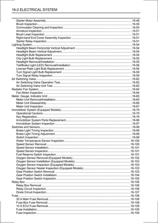

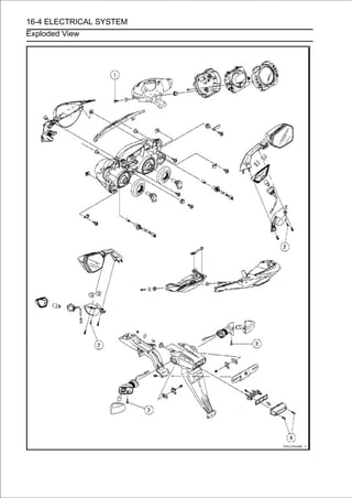
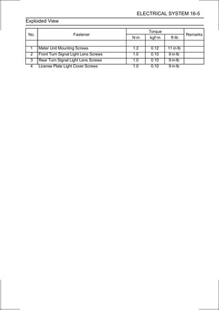
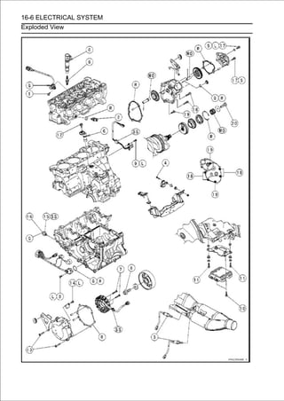
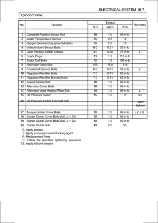
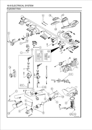
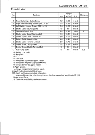
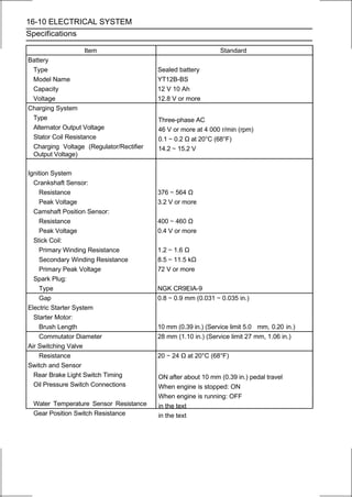
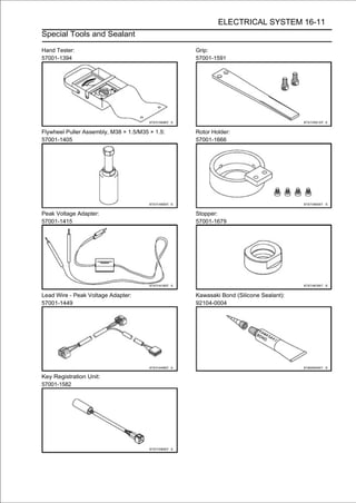
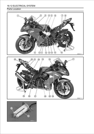
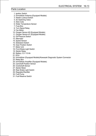
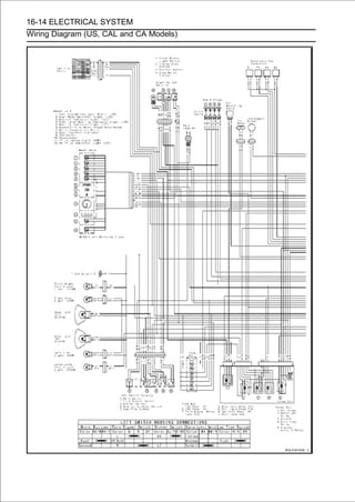
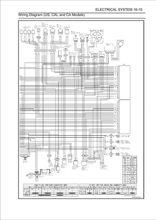
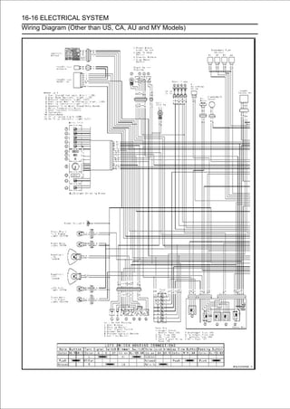
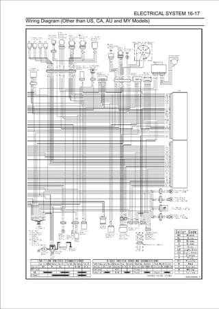
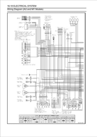
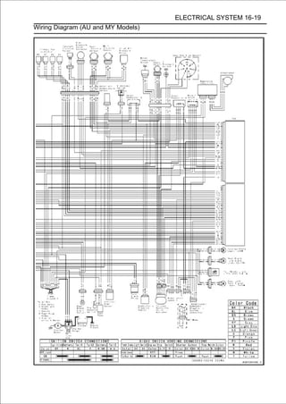
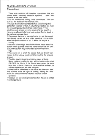
![ELECTRICAL SYSTEM 16-21
Electrical Wiring
Wiring Inspection
• Visually inspect the wiring for signs of burning, fraying,
etc.
If any wiring is poor, replace the damaged wiring.
• Pull each connector [A] apart and inspect it for corrosion,
dirt, and damage.
If the connector is corroded or dirty, clean it carefully. If it is
damaged, replace it.
• Check the wiring for continuity.
○Use the wiring diagram to find the ends of the lead which is
suspected of being a problem.
○Connect the hand tester between the ends of the leads.
Special Tool - Hand Tester: 57001-1394
○Set the tester to the × 1 Ω range, and read the tester.
If the tester does not read 0 Ω, the lead is defective. Re-
place the lead or the wiring harness [B] [C] if necessary.](https://image.slidesharecdn.com/2008-100321201635-phpapp01/85/2008-574-320.jpg)
![16-22 ELECTRICAL SYSTEM
Battery
Battery Removal
• Remove the front seat (see Front Seat Removal in the
Frame chapter).
• Slide the red cap [A].
• Disconnect the negative (-) cable [B] and then positive
(+) cable [C].
CAUTION
Be sure to disconnect the negative (-) cable first.
• Remove the band [D].
• Pull the battery [A] out of the case.
Battery Installation
• Visually inspect the surface of the battery container.
If any signs of cracking or electrolyte leakage from the
sides of the battery.
• Put the battery into the rear fender front so that the positive
(+) terminal faces right side of the motorcycle.
• Install the band [A].
• Connect the positive (+) cable [B] (red cap) to the positive
(+) terminal first, and then the negative (-) cable [C] to the
negative (-) terminal.
• Apply a light coat of grease on the terminals to prevent
corrosion.
• Cover the positive (+) terminal with the red cap [D].
CAUTION
If each battery cable is not correctly disconnected
or connected, sparks can arise at electrical connec-
tions, causing damage to electrical and DFI parts.
Battery Activation
Electrolyte Filling
• Make sure that the model name [A] of the electrolyte con-
tainer matches the model name [B] of the battery. These
names must be the same.
Battery Model Name for ZX1000E: YT12B-BS
CAUTION
Be sure to use the electrolyte container with the
same model name as the battery since the
electrolyte volume and specific gravity vary with
the battery type. This is to prevent overfilling of
the electrolyte, shorting the battery life, and
deterioration of the battery performance.](https://image.slidesharecdn.com/2008-100321201635-phpapp01/85/2008-575-320.jpg)
![ELECTRICAL SYSTEM 16-23
Battery
CAUTION
Do not remove the aluminum sealing sheet [A] from
the filler ports [B] until just prior to use. Be sure to
use the dedicated electrolyte container for correct
electrolyte volume.
• Place the battery on a level surface.
• Checkit.to see that the sealing sheet has no peeling, tears, or
holes in
• Remove the sealing sheet.
NOTE
○The battery is vacuum sealed. If the sealing sheet has
leaked air into the battery, it may require a longer initial
charge.
• Remove the electrolyte container from the vinyl bag.
• Detach the stripused later[A] seal the battery. and set
aside, these will be
of caps
to
from the container
NOTE
○Do not pierce or otherwise open the sealed cells [B] of
the electrolyte container. Do not attempt to separate
individual cells.
• Placecells into the fillercontainerthe battery. Hold the six
sealed
the electrolyte
ports of
upside down with the
container level, push down to break the seals of all six
cells. You will see air bubbles rising into each cell as the
ports fill.
NOTE
○Do not tilt the electrolyte container
• Check the electrolyte flow.
If no air bubbles [A] are coming up from the filler ports, or
if the container cells have not emptied completely, tap the
container [B] a few times.
• Keep the container in place for 20 minutes or more. Don’t
remove the container from the battery until it’s empty, the
battery requires all the electrolyte from the container for
proper operation.
CAUTION
Removal of the container before it is completely
empty can shorten the service life of the battery. Do
not remove the electrolyte container until it is com-
pletely empty and 20 minutes have elapsed.](https://image.slidesharecdn.com/2008-100321201635-phpapp01/85/2008-576-320.jpg)
![16-24 ELECTRICAL SYSTEM
Battery
• Gently remove the container from the battery.
• Let the batterypermeate into the plates for charging to allow
the electrolyte to
sit for 30 minutes prior to
optimum
performance.
NOTE
○Charging the battery immediately after filling can
shorten service life. Let the battery sit for at least 30
minutes after filling.
Initial Charge
• Place the strip [A] of caps loosely over the filler ports.
• Newly activated sealed batteries require an initial charge.
Standard Charge: 1.2 A × 5 ∼ 10 hours
If using a recommended battery charger, follow the
charger’s instructions for newly activated sealed battery.
Kawasaki-recommended chargers:
Optimate III
Yuasa 1.5 Amp Automatic Charger
Battery Mate 150-9
If the above chargers are not available, use equivalent
one.
NOTE
○Charging rates will vary depending on how long the
battery has been stored, temperature, and the type of
charger used. Let battery sit 30 minutes after initial
charge, then check voltage using a voltmeter. If it is
not at least 12.8 volts, repeat charging cycle.
• Aftertocharging is completed,[A] into the battery (don’t both
hands seat the strip of caps
press down firmly with
pound or hammer). When properly installed, the strip of
the caps will be level with the top of the battery.
CAUTION
Once the strip of the caps [A] is installed onto the
battery, never remove the caps, nor add water or
electrolyte to the battery.](https://image.slidesharecdn.com/2008-100321201635-phpapp01/85/2008-577-320.jpg)
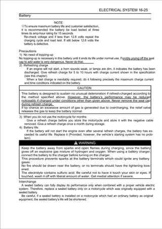
![16-26 ELECTRICAL SYSTEM
Battery
Charging Condition Inspection
○Battery charging condition can be checked by measuring
battery terminal voltage with a digital meter [A].
• Remove the front seat (see Front Seat Removal in the
Frame chapter).
• Slide the red cap and disconnect the battery cables from
the battery terminals (see Battery Removal).
CAUTION
Be sure to disconnect the negative (-) cable first.
• Measure the battery terminal voltage.
NOTE
○Measure with a digital voltmeter which can be read one
decimal place voltage.
If the reading is 12.8 V or more, no refresh charge is
required, however, if the read is below the specified, refresh
charge is required.
Battery Terminal Voltage
Standard: 12.8 V or more
Terminal Voltage (V) [A]
Battery Charge Rate (%) [B]
Good [C]
Refresh charge is required [D]
Refreshing Charge
• Remove the battery [A] (see Battery Removal).
• Do refresh charge by following method according to the
battery terminal voltage.
WARNING
This battery is sealed type. Never remove sealing
cap [B] even at charging. Never add water. Charge
with current and time as stated below.](https://image.slidesharecdn.com/2008-100321201635-phpapp01/85/2008-579-320.jpg)
![ELECTRICAL SYSTEM 16-27
Battery
Terminal Voltage: 11.5 ∼ less than 12.8 V
Standard Charge 1.2 A × 5 ∼ 10 h (see following chart)
Quick Charge 5 A×1 h
CAUTION
If possible, do not quick charge. If quick charge is
done unavoidably, do standard charge later on.
Terminal Voltage: less than 11.5 V
Charging Method: 1.2 A × 20 h
NOTE
○Increase the charging voltage to a maximum voltage of
25 V if the battery will not accept current initially. Charge
for no more than 5 minutes at the increased voltage then
check if the battery is drawing current. If the battery will
accept current decrease the voltage and charge by the
standard charging method described on the battery case.
If the battery will not accept current after 5 minutes,
replace the battery.
Battery [A]
Battery Charger [B]
Standard Value [C]
Current starts to flow [D]
• Determine the battery condition after refresh charge.
○Determine the condition of the battery left for 30 minutes
after completion of the charge by measuring the terminal
voltage according to the table below.
Criteria Judgement
12.8 V or higher Good
12.0 ∼ lower than 12.8 V Charge insufficient → Recharge
lower than 12.0 V Unserviceable → Replace](https://image.slidesharecdn.com/2008-100321201635-phpapp01/85/2008-580-320.jpg)
![16-28 ELECTRICAL SYSTEM
Charging System
Alternator Cover Removal
• Remove:
Left Lower Fairing (see Lower Fairing Removal in the
Frame chapter)
Coolant Reserve Tank (see Coolant Reserve Tank
Removal in the Cooling System chapter)
Fuel Tank (see Fuel Tank Removal in the Fuel System
(DFI) chapter)
Regulator/Rectifier Connector (Gray) [A]
• Remove:
Bolts [A]
Bracket [B]
Alternator Cover [C]
Alternator Cover Installation
• Apply silicone sealant to the alternator lead grommet and
crankcase halves mating surface [A] on the front and rear
sides of the cover mount.
Sealant - Kawasaki Bond (Silicone Sealant): 92104-0004
• Check that dowel pins [B] are in place on the crankcase.
• Replace the alternator cover gasket with a new one.
• Tighten:
Torque - Alternator Cover Bolts: 10 N·m (1.0 kgf·m, 89 in·lb)
• Run thethe Appendix chapter). Wire and Hose Routing
section in
lead correctly (see Cable,
Stator Coil Removal
• Remove:
Alternator Cover (see Alternator Cover Removal)
Holding Plate Bolt [A] and Plate
Alternator Lead Grommet [B]
Stator Coil Bolts [C]
• Remove the stator coil [D] from the alternator cover.](https://image.slidesharecdn.com/2008-100321201635-phpapp01/85/2008-581-320.jpg)
![ELECTRICAL SYSTEM 16-29
Charging System
Stator Coil Installation
• Tighten the stator coil bolts to the specified torque.
Torque - Stator Coil Bolts: 12 N·m (1.2 kgf·m, 106 in·lb)
• Applygrommet [A], and fit the grommet into theofnotch alterna-
tor lead
silicone sealant to the circumference the
of the cover securely.
Sealant - Kawasaki Bond (Silicone Sealant): 92104-0004
• Secure the alternator lead with a to the thread of[B], and
apply a non-permanent locking agent
holding plate
the
plate bolt [C] and tighten it.
Torque - Alternator Lead Holding Plate Bolt: 10 N·m (1.0
kgf·m, 89 in·lb)
• Install the alternator cover (see Alternator Cover Installa-
tion).
Alternator Rotor Removal
• Remove the alternator cover (see Alternator Cover Re-
moval).
• Clean off the oil from the outer circumference of the rotor.
• Hold the alternator rotor steady with the rotor holder [A],
and remove the rotor bolt [B] and washer.
Special Tools - Grip [C]: 57001-1591
Rotor Holder: 57001-1666
Stopper [D]: 57001-1679
• Using crankshaft. puller [A], remove the alternator rotor
from the
the flywheel
Special Tool - Flywheel Puller Assembly, M38 × 1.5/M35 ×
1.5: 57001-1405
CAUTION
Do not attempt to strike the alternator rotor itself.
Striking the rotor can cause the magnets to lose
their magnetism.
Alternator Rotor Installation
• Using a cleaning fluid, clean off any oil or dirt on the
following portions and dry them with a clean cloth.
Crankshaft Tapered Portion [A]
Alternator Rotor Tapered Portion [B]
• Install the alternator rotor.](https://image.slidesharecdn.com/2008-100321201635-phpapp01/85/2008-582-320.jpg)
![16-30 ELECTRICAL SYSTEM
Charging System
• Using[A] and dry it with a clean cloth.any oil or dirt on the
washer
a cleaning fluid, clean off
• Install the washer.
NOTE
○Confirm the alternator rotor fit or not to the crankshaft
before tightening it with specified torque.
• Install the rotor bolt [B] and tighten it with 70 N·m (7.0
kgf·m, 52 ft·lb) of torque.
• Remove the rotor bolt and washer.
• Check the tightening torque with flywheel puller [A].
Special Tool - Flywheel Puller Assembly, M38 × 1.5/M35 ×
1.5: 57001-1405
If the rotor is not pulled out with 20 N·m (2.0 kgf·m, 15
ft·lb) of drawing torque, it is installed correctly.
If the rotor is pulled out with under 20 N·m (2.0 kgf·m, 15
ft·lb) of drawing torque, clean off any oil dirt or flaw of the
crankshaft and rotor tapered portion, and dry them with
a clean cloth. Then, confirm that it is not pulled out with
above torque.
• Install the rotor bolt and washer.
• Tighten thewith the holder [B]. [A] while holding the alternator
rotor steadily
alternator rotor bolt
Special Tools - Grip [C]: 57001-1591
Rotor Holder: 57001-1666
Stopper [D]: 57001-1679
Torque - Alternator Rotor Bolt: 155 N·m (15.8 kgf·m, 114
ft·lb)
• Install the alternator cover (see Alternator Cover Installa-
tion).
Alternator Inspection
There are three types of alternator failures: short, open
(wire burned out), or loss in rotor magnetism. A short or
open in one of the coil wires will result in either a low output,
or no output at all. A loss in rotor magnetism, which may be
caused by dropping or hitting the alternator, by leaving it
near an electromagnetic field, or just by aging, will result in
low output.](https://image.slidesharecdn.com/2008-100321201635-phpapp01/85/2008-583-320.jpg)
![ELECTRICAL SYSTEM 16-31
Charging System
• To check the alternator output voltage, do the following
procedures.
○Turn the ignition switch OFF.
• Disconnect:
Regulator/Rectifier Connector (Gray) [A]
○Connect the hand tester as shown in the table 1.
Special Tool - Hand Tester: 57001-1394
○Start the engine.
○Run it at the rpm given in the table 1.
○Note the voltage readings (total 3 measurements).
Table 1 Alternator Output Voltage
Tester Connections Reading
Range Tester (+) to Tester (-) to at 4 000 rpm
AC 250 V One W lead Another W lead 46 V or more
If the output voltage shows the value in the table, the
alternator operates properly.
If the output voltage shows a much higher than the value in
the table, the regulator/rectifier is damaged. A much
lower reading than that given in the table indicates that
the alternator is defective.
• Check the stator coil resistance as follows.
○Stop the engine.
○Connect the hand tester as shown in the table 2.
Special Tool - Hand Tester: 57001-1394
○Note the readings (total 3 measurement).
Table 2 Stator Coil Resistance at 20°C (68°F)
Tester Connections
Range Tester (+) to Tester (-) to Reading
×1Ω One W lead Another W lead 0.1 ∼ 0.2 Ω
If there is more resistance than shown in the table, or
no tester reading (infinity) for any two leads, the stator
has an open lead and must be replaced. Much less than
this resistance means the stator is shorted, and must be
replaced.
• Using the highest resistance range of the hand tester,
measure the resistance between each of the white leads
and chassis ground.
Any hand tester reading less than infinity (∞) indicates a
short, necessitating stator replacement.
If the stator coil has normal resistance, but the voltage
check showed the alternator to be defective; then the rotor
magnets have probably weakened, and the rotor must be
replaced.](https://image.slidesharecdn.com/2008-100321201635-phpapp01/85/2008-584-320.jpg)
![16-32 ELECTRICAL SYSTEM
Charging System
Regulator/Rectifier Inspection
•Disconnect the regulator/rectifier connectors [A].
•Remove the regulator/rectifier bracket bolt [B].
• Remove the rear brake reservoir mounting bolt [A].
• Remove the regulator/rectifier bracket bolts [A], and take off
the regulator/rectifier [B] together with the bracket.
• Remove the regulator/rectifier bolts [A], and separate the
regulator/rectifier [B] and bracket.
• Set the handshown into the × 1 kΩ range and make the
measurements
tester
the table.
Special Tool - Hand Tester: 57001-1394
• Connect the hand tester to the regulator rectifier.
If the tester readings are not as specified, replace the
regulator/rectifier.
CAUTION
Use only Kawasaki Hand Tester 57001-1394 for this
test. A tester other than the Kawasaki Hand Tester
may show different readings.
If a megger or a meter with a large capacity battery
is used, the regulator/rectifier will be damaged.](https://image.slidesharecdn.com/2008-100321201635-phpapp01/85/2008-585-320.jpg)
![ELECTRICAL SYSTEM 16-33
Charging System
Regulator/Rectifier Resistance (Unit: kΩ)
Tester (+) Lead Connection
Terminal W1 W2 W3 W4 BK/G BK
W1 - 0 0 3∼11 0 0
W2 0 - 0 3∼11 0 0
W3 0 0 - 3∼11 0 0
(-)* W4 0 0 0 - 0 0
BK/G 0 0 0 3∼11 - 0
BK 3∼11 3∼11 3∼11 6∼18 3∼11 -
(−)*: Tester (−) Lead Connection
• Be sure to install the following on the regulator/rectifier
bracket [A].
Rubber Dampers [B]
Collars [C]
• Install the regulator/rectifier [D] on the bracket as shown in
the figure.
Torque - Regulator/Rectifier Bolts [E]: 7.0 N·m (0.71 kgf·m,
62 in·lb)
• Tighten:
Torque - Regulator/Rectifier Bracket Bolts: 7.0 N·m (0.71
kgf·m, 62 in·lb)](https://image.slidesharecdn.com/2008-100321201635-phpapp01/85/2008-586-320.jpg)
![16-34 ELECTRICAL SYSTEM
Charging System
Charging Voltage Inspection
• Check the battery condition (see Charging Condition
Inspection).
• Warm up the engine to obtain actual alternator operating
conditions.
• Remove the front seat (see Front Seat Removal in the
Frame chapter).
• Check that the ignition switch is turned off, and connect
the hand tester [A] to the battery terminals [B].
Special Tool - Hand Tester: 57001-1394
• Start thespeeds with the headlight turned on and then vari-
ous engine
engine, and note the voltage readings at
turned off (To turn off the headlight, disconnect the head-
light connector.). The readings should show nearly bat-
tery voltage when the engine speed is low, and, as the
engine speed rises, the readings should also rise. But
they must be kept under the specified voltage.
Charging Voltage
Connections
Tester Range Reading
Tester (+) to Tester (-) to
DC 25 V Battery (+) Battery (-) 14.2 ∼ 15.2 V
• Turn offtester. switch to stop the engine, and disconnect
the hand
the ignition
If the charging voltage is kept between the values given in
the table, the charging system is considered to be working
normally.
If the charging voltage is much higher than the values
specified in the table, the regulator/rectifier is defective
or the regulator/rectifier leads are loose or open.
If the charging voltage does not rise as the engine speed
increases, then the regulator/rectifier is defective or the
alternator output is insufficient for the loads. Check the
alternator and regulator/rectifier to determine which part
is defective.](https://image.slidesharecdn.com/2008-100321201635-phpapp01/85/2008-587-320.jpg)

![16-36 ELECTRICAL SYSTEM
Ignition System
WARNING
The ignition system produces extremely high
voltage. Do not touch the spark plugs or stick
coils while the engine is running, or you could
receive a severe electrical shock.
CAUTION
Do not disconnect the battery cables or any other
electrical connections when the ignition switch is
on, or while the engine is running. This is to prevent
ECU damage.
Do not install the battery backwards. The negative
side is grounded. This is to prevent damage to the
ECU.
Crankshaft Sensor Removal
•Remove:
Fuel Tank (see Fuel Tank Removal in the Fuel System
(DFI) chapter)
Crankshaft Sensor Lead Connector [A]
• Remove:
Starter Idle Gear (see Starter Idle Gear Removal in the
Crankshaft/Transmission chapter)
Bolts [A]
Crankshaft Sensor Lead Grommet [B]
Crankshaft Sensor [C]
Crankshaft Sensor Installation
• Apply a non-permanent locking agent to the threads of
the crankshaft sensor bolts [A], and tighten them.
Torque - Crankshaft Sensor Bolts: 6.0 N·m (0.61 kgf·m, 53
in·lb)
• Apply silicone sealant to[B], and fit the grommetthe crank-
shaft sensor lead grommet
the circumference of
into
the notch of the crankcase securely.
Sealant - Kawasaki Bond (Silicone Sealant): 92104-0004
• Install the removed parts (see appropriate chapters).
• Run the crankshaft section inlead Appendix chapter).
Wire, and Hose Routing
sensor
the
correctly (see Cable,](https://image.slidesharecdn.com/2008-100321201635-phpapp01/85/2008-589-320.jpg)
![ELECTRICAL SYSTEM 16-37
Ignition System
Crankshaft Sensor Inspection
• Disconnect the crankshaft sensor lead connector (see
Crankshaft Sensor Removal).
• Set the hand tester [A] to the × 10 Ω range and connect it to
the crankshaft sensor lead connector [B].
Special Tool - Hand Tester: 57001-1394
Crankshaft Sensor Resistance
Connections: Y lead ←→ BK lead
Standard: 376 ∼ 564 Ω
If there is more resistance than the specified value, the
coil has an open lead and must be replaced. Much less
than this resistance means the coil is shorted, and must
be replaced.
• Using the highest resistance rangesensor leads and
the resistance between the crankshaft
of the tester, measure
chassis ground.
Any tester reading less than infinity (∞) indicates a short,
necessitating replacement of the crankshaft sensor.
Crankshaft Sensor Peak Voltage Inspection
NOTE
○Be sure the battery is fully charged.
○Using the peak voltage adapter [A] is more reliable way
to determine the condition of the crankshaft sensor than
crankshaft sensor internal resistance measurements.
• Crankshaft Sensor Removal). lead connector (see
Disconnect the crankshaft sensor
• itSet thevoltage adapter.to the DC 10 V range, and connect
peak
hand tester [B]
Special Tools - Hand Tester: 57001-1394
Peak Voltage Adapter: 57001-1415
Type: KEK-54-9-B
• Connect the connector [C]. terminals of the crankshaft
sensor lead
adapter to the
Connections:
Crankshaft Sensor Peak Voltage
Lead Connector Adapter Hand Tester
Y lead [D] ← R lead → (+)
BK lead [E] ← BK lead → (-)
• Turn the engine stop switch to run position.
• Turn the ignition switch ON.
• Pushing transmission in neutral to measure4the5peak volt-
with the
the starter button, turn the engine ∼ seconds
age.
• Crankshaft Sensor Peak Voltage
Repeat the measurements 5 times or more times.
Standard: 3.2 V or more
If the reading is less than the standard, inspect the
crankshaft sensor (see Crankshaft Sensor Inspection).](https://image.slidesharecdn.com/2008-100321201635-phpapp01/85/2008-590-320.jpg)
![16-38 ELECTRICAL SYSTEM
Ignition System
Camshaft Position Sensor Removal
• Remove the air cleaner housing (see Air Cleaner Housing
Removal in the Fuel System (DFI) chapter).
• Disconnect the camshaft position sensor lead connector
[A].
• Remove:
Camshaft Position Sensor Bolt [A]
Camshaft Position Sensor [B]
Camshaft Position Sensor Installation
•Apply grease to the O-ring [A].
•Tighten:
Torque - Camshaft Position Sensor Bolt: 10 N·m (1.0 kgf·m,
89 in·lb)
• Run thethe Appendix chapter). Wire, and Hose Routing
section in
lead correctly (see Cable,
Camshaft Position Sensor Inspection
• Disconnect the camshaft position sensor lead connector
(see Camshaft Position Sensor Removal).
• Set the hand tester [A] to the × 10 Ω range and connect it to
the camshaft position sensor lead connector [B].
Special Tool - Hand Tester: 57001-1394
Camshaft Position Sensor Resistance
Connections: W/Y lead ←→ Y lead
Standard: 400 ∼ 460 Ω
If there is more resistance than the specified value, the
sensor coil has an open lead and must be replaced. Much
less than this resistance means the sensor coil is shorted,
and must be replaced.
• Using the highest resistance range of the tester, mea-
sure the resistance between the camshaft position sensor
leads and chassis ground.
Any tester reading less than infinity (∞) indicates a short,
necessitating replacement of the camshaft position sen-
sor.](https://image.slidesharecdn.com/2008-100321201635-phpapp01/85/2008-591-320.jpg)
![ELECTRICAL SYSTEM 16-39
Ignition System
Camshaft Position Sensor Peak Voltage
Inspection
• Disconnect the camshaft position sensor lead connector
(see Camshaft Position Sensor Removal).
• Set the hand tester [A] to the DC 2.5 V range, and connect
it peak voltage adapter [B].
Special Tool - Hand Tester: 57001-1394
Peak Voltage Adapter: 57001-1415
Type: KEK-54-9-B
• Connect the adapter to the terminals of the camshaft po-
sition sensor lead connector [C].
Connections:
Camshaft Position
Sensor Lead Peak Voltage Hand Tester
Adapter
Connector
W/Y lead [D] ← R lead → (+)
Y lead [E] ← BK lead → (-)
• Turn the engine stop switch to run position.
• Turn the ignition switch ON.
• Pushing the starter button, turn the engine 4 ∼ 5 seconds
with the transmission in neutral to measure the peak volt-
age.
• Camshaft Position Sensor Peak Voltage
Repeat the measurements 5 times or more times.
Standard: 0.4 V or more
If the reading is less than the standard, inspect the
camshaft position sensor (see Camshaft Position Sensor
Inspection).
Stick Coil Removal
• Remove the air cleaner housing (see Air Cleaner Housing
Removal in the Fuel System (DFI) chapter).
• Disconnect the stick coil connectors [A].
• Pull out the stick coils #2, #3 [B] upward.
CAUTION
Do not pry the connector part of the coil while
removing the coil.
• Remove the stick coil #1 as follows.
○Remove:
Upper Fairing Assembly (see Upper Fairing Assembly
Removal in the Frame chapter)
Coolant Reserve Tank (see Coolant Reserve Tank
Removal in the Cooling System chapter)
Left Upper Inner Fairing Bracket Bolts [A]
Left Upper Inner Fairing Bracket [B]](https://image.slidesharecdn.com/2008-100321201635-phpapp01/85/2008-592-320.jpg)
![16-40 ELECTRICAL SYSTEM
Ignition System
○Remove:
Left Engine Bracket Bolts [A]
Left Engine Bracket [B]
○Pull out the stick coil #1 [A] forward.
• Remove the stick coil #4 as follows.
○Remove:
Upper Fairing Assembly (see Upper Fairing Assembly
Removal in the Frame chapter)
Right Upper Inner Fairing Bracket Bolts [A]
Right Upper Inner Fairing Bracket [B]
○Remove:
Right Engine Bracket Bolts [A]
Right Engine Bracket [B]
○Pull out the stick coil #4 [A] forward.](https://image.slidesharecdn.com/2008-100321201635-phpapp01/85/2008-593-320.jpg)
![ELECTRICAL SYSTEM 16-41
Ignition System
Stick Coil Installation
• Apply a thin coat of grease [A] to the stick coils for easy
installation.
• Insert [B] on thecoils [A] head cover. coil heads align with
the lines
the stick
cylinder
so that the
CAUTION
Do not tap the coil head while installing the coil.
• After by pulling upbe sure the stick coils are installed
securely
installation,
them lightly.
• Run theAppendix chapter). Cable, Wire, and Hose Routing
section in
leads correctly (see
• Install thetheleft and Removal/Installation chapter). Engine
Installation in Engine
right engine bracket (see
• Install the removed parts (see appropriate chapters).
Stick Coil Inspection
• Remove the stick coils (see Stick Coil Removal).
• Measure the primary winding resistance [A] as follows.
○Connect the hand tester between the coil terminals.
○Set the tester to the × 1 Ω range, and read the tester.
• Measure the secondary winding resistance [B] as follows.
○Connect the tester between the plug terminal and (-) coil
terminal.
○Set the tester to the × 1 kΩ range and read the tester.
Stick Coil Winding Resistance
Primary Windings: 1.2 ∼ 1.6 Ω
Secondary Windings: 8.5 ∼ 11.5 kΩ
If the tester does not read as specified, replace the coil.](https://image.slidesharecdn.com/2008-100321201635-phpapp01/85/2008-594-320.jpg)
![16-42 ELECTRICAL SYSTEM
Ignition System
Stick Coil Primary Peak Voltage
NOTE
○Be sure the battery is fully charged.
• Remove the stick coils (see Stick Coil Removal).
○Do not remove the spark plug.
• Measure the primary peak voltage as follows.
○Install the new spark plug [A] into each stick coil [B], and
ground them onto the engine.
○Connect the peak voltage adapter [C] into the hand tester [D]
which is set to the DC 250 V range.
○Connect the adapter to the lead wire-peak voltage
adapter [E] which is connected between the stick coil
connector and stick coil.
ECU [F]
Battery [G]
Special Tools - Hand Tester: 57001-1394
Peak Voltage Adapter: 57001-1415
Type: KEK-54-9-B
Lead Wire-Peak Voltage Adapter: 57001
-1449
Connections:
Adapter (R, +) → Lead Wire-Peak Voltage Adapter (W)
Adapter (BK, -) → Lead Wire-Peak Voltage Adapter (R)
WARNING
To avoid extremely high voltage shocks, do not
touch the spark plugs or tester connections.
• Turn the engine stop switch to run position.
• Turn the ignition switch ON.
• Pushing the starter button, turn the primary 4 ∼ 5 seconds
with the transmission in neutral to measure the engine
peak voltage.
• Repeat the measurements 5 times for one stick coil.
Stick Coil Primary Peak Voltage
Standard: 72 V or more
• Repeat the test for the other stick coils.
If the reading is less than the specified value, check the
following.
Stick Coils (see Stick Coil Inspection)
Crankshaft Sensor (see Crankshaft Sensor Inspection)
ECU (see ECU Power Supply Inspection in the Fuel System
(DFI) chapter)
Spark Plug Removal
• Refer to the Spark Plug Replacement in the Periodic
Maintenance chapter.
Spark Plug Installation
• Refer to the Spark Plug Replacement in the Periodic
Maintenance chapter.](https://image.slidesharecdn.com/2008-100321201635-phpapp01/85/2008-595-320.jpg)
![ELECTRICAL SYSTEM 16-43
Ignition System
Spark Plug Condition Inspection
• Visually inspect the spark plugs.
If the spark plug center electrode [A] and/or side elec-
trode [B] are corroded or damaged, or if the insulator [C] is
cracked, replace the plug.
If the spark plug is dirtied or the carbon is accumulated,
replace the spark plug.
• Measure the gap [D] with a wire-type thickness gauge. If
the gap is incorrect, replace the spark plug.
Spark Plug Gap: 0.8 ∼ 0.9 mm (0.031 ∼ 0.035 in.)
• Use the standard spark plug or its equivalent.
Standard Spark Plug:
Type: CR9EIA-9
Interlock Operation Inspection
• Raise the rear wheel off the ground with the stand [A].
1st Check
• Start the engine to the following conditions.
Condition:
Transmission Gear → 1st Position
Clutch Lever → Release
Sidestand → Down or Up
○Turn the ignition switch ON and push the starter button.
○Then the starter motor should not turn when the starter
system circuit is normality.
If the engine is start, inspect the starter lockout switch,
gear position switch, and relay box.
If their parts are normality replace the ECU.
2nd Check
• Start the engine to the following conditions.
Condition:
Transmission Gear → 1st Position
Clutch Lever → Pulled in
Sidestand → Up
○Turn the ignition switch ON and push the starter button.
○Then the starter motor should turn when the starter system
circuit is normality.
If the starter motor is not turn, inspect the starter lockout
switch, gear position switch, sidestand switch and relay
box.
If their parts are normality, replace the ECU.](https://image.slidesharecdn.com/2008-100321201635-phpapp01/85/2008-596-320.jpg)
![16-44 ELECTRICAL SYSTEM
Ignition System
3rd Check
• Inspect the engine for its secure stop after the following
operations are completed.
• Run the engine to the following conditions.
Condition:
Transmission Gear → 1st Position
Clutch Lever → Release
Sidestand → Up
• whichever may not on stopped, inspect the gear positionstop.
If
Set the sidestand
be
the ground, then the engine will
switch, starter lockout switch, sidestand switch and relay
box.
If their parts are normality, replace the ECU.
IC Igniter Inspection
○The IC igniter is built in the ECU [A].
• Refer to the following items.
Interlock Operation Inspection (see Interlock Operation
Inspection)
Ignition System Troubleshooting (see Ignition System
section)
ECU Power Supply Inspection (see ECU Power Supply
Inspection in the Fuel System (DFI) chapter)](https://image.slidesharecdn.com/2008-100321201635-phpapp01/85/2008-597-320.jpg)
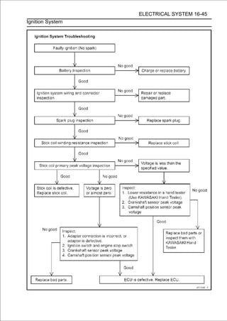
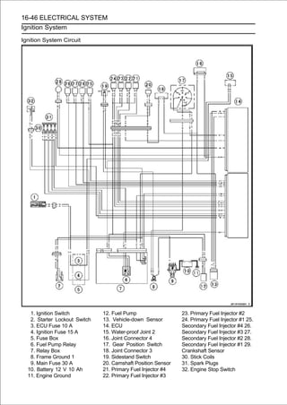
![ELECTRICAL SYSTEM 16-47
Electric Starter System
Starter Motor Removal
• Drain the coolant (see Coolant Change in the Periodic
Maintenance chapter).
• Remove:
Throttle Body Assy (see Throttle Body Assy Removal in
the Fuel System (DFI) chapter)
Starter Clutch Cover (see Starter Idle Gear Removal in
the Crankshaft/Transmission chapter)
Water Hose [A]
• Slide out the rubber cap [A].
• Remove the starter motor cable terminal nut [B].
• Remove the starter motor mounting bolts [A].
• Take out the starter motor [B] from the right side of the
motorcycle.
Starter Motor Installation
CAUTION
Do not tap the starter motor shaft or body. Tapping
the shaft or body could damage the motor.
• Clean the starterground. legs [A] and crankcase [B] where
the starter motor is
motor
• Replace the O-rings [A] with new ones.
• Apply grease to the new O-rings.
• Set the starter motor mounting bolts [B].
• Tighten the starter motor mounting bolts temporarily.
• Install the the Crankshaft/Transmission chapter).Idle
Installation in
starter clutch cover (see Starter Gear
• Tighten:
Torque - Starter Motor Mounting Bolts: 10 N·m (1.0 kgf·m,
89 in·lb)](https://image.slidesharecdn.com/2008-100321201635-phpapp01/85/2008-600-320.jpg)
![16-48 ELECTRICAL SYSTEM
Electric Starter System
• Run the starter motor (see Engine Installationinsulation rub-
ber plate and water hose
cable under the heat
in the
Engine Removal/Installation chapter).
• Install the starter motor cable [A] as shown in the figure.
About 45° [B]
Front [C]
• Tighten:
Torque - Starter Motor Cable Terminal Nut: 6.0 N·m (0.61
kgf·m, 53 in·lb)
• Slide back the rubber cap to the original position.
Starter Motor Disassembly
• Remove the starter motor (see Starter Motor Removal).
• Take off the starter motor through bolts [A] and remove
both end covers [B].
• Pull the armature [A] out of the yoke [B].
• Remove:
Starter Motor Terminal Locknut [A]
Brush Plate Assembly [B]
Starter Motor Assembly
• Pry the spring end [A] and insert the brush [B].](https://image.slidesharecdn.com/2008-100321201635-phpapp01/85/2008-601-320.jpg)
![ELECTRICAL SYSTEM 16-49
Electric Starter System
• Install the brush plate assembly [A] into the right-hand end
cover [B].
• Replace the O-ring [C] with a new one.
• Install:
Insulators [D]
Washer [E]
• Tighten:
Torque - Starter Motor Terminal Locknut [F]: 6.9 N·m (0.70
kgf·m, 61 in·lb)
• Install the armature [A] into the yoke [B].
• Install the slip [C] and thrust washers [D] onto each side of
the shaft.
• Replace the O-rings [A] with new ones.
• Put the armature [B] among the brushes [C].
• Apply a thin coat of grease to the oil seal [A].
• Fit the toothed washer [B] into the left-hand end cover.
• Align the marks [A] to assembly the yoke and the end
covers.](https://image.slidesharecdn.com/2008-100321201635-phpapp01/85/2008-602-320.jpg)
![16-50 ELECTRICAL SYSTEM
Electric Starter System
• Replace the O-rings [A] with new ones.
• Tighten:
Torque - Starter Motor Through Bolts [B]: 3.4 N·m (0.35
kgf·m, 30 in·lb)
• Replace the O-rings [A] with new ones.
• Apply grease to the new O-rings.
Brush Inspection
•Measure the length [A] of each brush [B].
If any is worn down to the service limit, replace the brush
holder assembly.
Starter Motor Brush Length
Standard: 10 mm (0.39 in.)
Service Limit: 5.0 mm (0.20 in.)
Commutator Cleaning and Inspection
• Smooth the commutator surface [A] if necessary with fine
emery cloth [B], and clean out the grooves.
• Measure the diameter [A] of the commutator [B].
If the commutator diameter is less than the service limit,
replace the starter motor with a new one .
Commutator Diameter
Standard: 28 mm (1.10 in.)
Service Limit: 27 mm (1.06 in.)](https://image.slidesharecdn.com/2008-100321201635-phpapp01/85/2008-603-320.jpg)
![ELECTRICAL SYSTEM 16-51
Electric Starter System
Armature Inspection
• Using the × 1 Ω hand tester range, measure the
resistance between any two commutator segments [A].
Special Tool - Hand Tester: 57001-1394
If there is a high resistance or no reading (∞) between any
two segments, a winding is open and the starter motor
must be replaced.
• Using the highest hand tester range, measure the
resistance between the segments and the shaft [B].
If there is any reading at all, the armature has a short and the
starter motor must be replaced.
NOTE
○Even if the foregoing checks show the armature to be
good, it may be defective in some manner not readily
detectable with the hand tester. If all other starter motor
and starter motor circuit components check good, but
the starter motor still does not turn over or only turns
over weakly, replace the starter motor with a new one.
Brush Lead Inspection
• Using the × 1 Ω hand tester range, measure the
resistance as shown in the figure.
Terminal Bolt and Positive Brush [A]
Right-hand End Cover and Negative Brush [B]
Special Tool - Hand Tester: 57001-1394
If there is not close to zero ohms, the brush lead has an
open. Replace the brush holder assembly.
Right-hand End Cover Assembly Inspection
• Using the highest hand tester range, measure the
resistance as shown in the figure.
Terminal Bolt and Right-hand End Cover [A]
Special Tool - Hand Tester: 57001-1394
If there is any reading, the right-hand end cover assembly
have a short. Replace the starter motor.
Starter Relay Inspection
• Remove the battery negative (-) cable from the battery
negative (-) terminal (see Battery Removal).
• Remove the fuel tank (see Fuel Tank Removal in the Fuel
System (DFI) chapter).
• Remove the starter motor cable [A] and battery positive
(+) cable [B].
• Pull out the starter relay [C] from the bracket on the frame.](https://image.slidesharecdn.com/2008-100321201635-phpapp01/85/2008-604-320.jpg)
![16-52 ELECTRICAL SYSTEM
Electric Starter System
• Disconnect the connector [A].
• Connect the as shown in the figure. V battery [B] to the
starter relay [C]
hand tester [A] and 12
Special Tool - Hand Tester: 57001-1394
If the relay does not work as specified, the relay is defective.
Replace the relay.
Testing Relay
Tester Range: ×1Ωrange
Criteria: When battery is connected → 0 Ω
When battery is disconnected → ∞ Ω
• Tighten:
Torque - Starter Motor Cable Mounting Bolt: 4.0 N·m (0.41
kgf·m, 35 in·lb)
Battery Cable Mounting Bolt: 4.0 N·m (0.41 kgf·m,
35 in·lb)](https://image.slidesharecdn.com/2008-100321201635-phpapp01/85/2008-605-320.jpg)
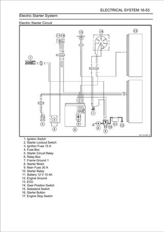
![16-54 ELECTRICAL SYSTEM
Lighting System
This motorcycle adopt the daylight system and have a
headlight relay in the relay box. The headlight does not
go on when the ignition switch and the engine stop switch
are first turned on. The headlight comes on after the starter
button is released and stays on until the ignition switch is
turned off. The headlight will go out momentarily whenever
the starter button is pressed and come back on when the
button is released.
Headlight Beam Horizontal Vertical Adjustment
• Refer to the Headlight Aiming Inspection in the Periodic
Maintenance chapter.
Headlight Beam Vertical Adjustment
• Refer to the Headlight Aiming Inspection in the Periodic
Maintenance chapter.
Headlight Bulb Replacement
• Remove the upper inner fairing (see Upper Inner Fairing
Removal in the Frame chapter).
•Disconnect the headlight connector [A].
• Turn the headlight bulb [A] counterclockwise and pull out
the bulb from the headlight.
CAUTION
When handling the quartz-halogen bulb, never
touch the glass portion with bare hands. Always
use a clean cloth. Oil contamination from hands or
dirty rags can reduce bulb life or cause the bulb to
explode.
NOTE
○Clean off any contamination that inadvertently gets on
the bulb with alcohol or soap and water solution.
• Replace the headlight bulb.
• Fit the projection [A] of the bulb in the hollow [B] of the
headlight.](https://image.slidesharecdn.com/2008-100321201635-phpapp01/85/2008-607-320.jpg)
![ELECTRICAL SYSTEM 16-55
Lighting System
• Turn the headlight bulb [A] clockwise.
• Connect the headlight connector.
• After Inspection in adjust the headlight aim (see Headlight
Aiming
installation,
the Periodic Maintenance chapter).
○Other Bulb: Repeat the above steps.
City Light Bulb Replacement
• Remove the upper inner fairing (see Upper Inner Fairing
Removal in the Frame chapter).
• Open the clamp [A].
• Pull out the socket [B] together with the bulb.
• Pull the bulb [A] out of the socket [B].
CAUTION
Do not turn the bulb. Pull the bulb out to prevent
damage to the bulb. Do not use bulb rated for
greater wattage than the specified value.
• Replace the bulb with a new one.
• Insert the socket [A] to the headlight.
○Fit the socket into the grooves [B] of the headlight.
○Other Bulb: Repeat the above steps.
Headlight Removal/Installation
•Remove:
Upper Fairing Assembly (see Upper Fairing Assembly
Removal in the Frame chapter)
Quick Rivet [A]
Bolts [B] and Clamps [C]
Headlight [D]
○Push the central pin, and then remove the quick rivet.
• Run the leads correctly (see of removal, note Hosefollowing.
○
Installation is the reverse
Cable, Wire, and
the
Rout-
ing section in the Appendix chapter).](https://image.slidesharecdn.com/2008-100321201635-phpapp01/85/2008-608-320.jpg)
![16-56 ELECTRICAL SYSTEM
Lighting System
Tail/Brake Light (LED) Removal/Installation
•Remove:
Rear Fender Rear (see Flap and Rear Fender Rear Re-
moval in the Frame chapter)
Bolts [A]
Tail/Brake Light [B]
• Fit the projections [A] of the rear fender rear into the slots
○
Installation is the reverse of removal, note the following.
[B] of the tail/brake light.
License Plate Light Bulb Replacement
• Remove:
Screws [A]
License Plate Light Cover [B]
• Pull the bulb [A] out of the socket [B].
CAUTION
Do not turn the bulb. Pull the bulb out to prevent
damage to the bulb. Do not use bulb rated for
greater wattage than the specified value.
• Replace the bulb with a new one.
• Tighten:
Torque - Licence Plate Light Cover Screws: 1.0 N·m (0.10
kgf·m, 9 in·lb)](https://image.slidesharecdn.com/2008-100321201635-phpapp01/85/2008-609-320.jpg)
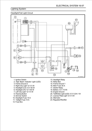
![16-58 ELECTRICAL SYSTEM
Lighting System
Turn Signal Light Bulb Replacement
Front Turn Signal Light
• Remove:
Screw [A]
Front Turn Signal Light Lens [B]
• Push and turn the frontit. turn
counterclockwise and remove
signal light bulb [A]
• Replace the bulb with a new one.
• Insert left and right grooves aligning its left and right pins [B]
with the
the new bulb [A] by
[C] in the socket, and turn
the bulb clockwise.
○Turn the bulb about 15°.
• Fitsignalprojection [A] of the lens into the groove [B] of the
turn
the
light.
• Tighten:
Torque - Front Turn Signal Light Lens Screw: 1.0 N·m (0.10
kgf·m, 9 in·lb)
○Other Bulb: Repeat the above steps.
Rear Turn Signal Light
• Remove:
Screw [A]
Rear Turn Signal Light Lens [B]](https://image.slidesharecdn.com/2008-100321201635-phpapp01/85/2008-611-320.jpg)
![ELECTRICAL SYSTEM 16-59
Lighting System
• Push and turn the rearit. turn
counterclockwise and remove
signal light bulb [A]
• Insert left and right grooves aligning its left and right pins [B]
with the
the new bulb [A] by
[C] in the socket, and turn
the bulb clockwise.
○Turn the bulb about 15°.
• Fitsignalprojection [A] of the lens into the groove [B] of the
turn
the
light.
• Tighten:
Torque - Rear Turn Signal Light Lens Screw: 1.0 N·m (0.10
kgf·m, 9 in·lb)
○Other Bulb: Repeat the above steps.
Turn Signal Relay Inspection
• Remove the center seat cover (see Seat Cover Removal in
the Frame chapter).
• Disconnect the connector [A].
• Pull out the turn signal relay [B] backward, and remove it
from the rubber protector [C].](https://image.slidesharecdn.com/2008-100321201635-phpapp01/85/2008-612-320.jpg)
![16-60 ELECTRICAL SYSTEM
Lighting System
• Connect one 12andbattery how manysignal the lights indi-
cated in the figure,
V
count
and turn
times
lights as
flash for one minute.
Turn Signal Relay [A]
Turn Signal Lights [B]
12 V Battery [C]
If the lights do not flash as specified, replace the turn signal
relay.
Testing Turn Signal Relay
Load
The Number of Turn Flashing Times
Wattage (W) (c/m*)
Signal Lights
1** 10 140-250
2 20 75-95
*: Cycle(s) per minute
**: Correspond to “one light burned out”](https://image.slidesharecdn.com/2008-100321201635-phpapp01/85/2008-613-320.jpg)
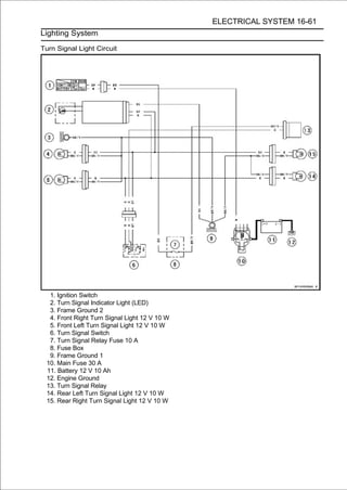
![16-62 ELECTRICAL SYSTEM
Air Switching Valve
Air Switching Valve Operation Test
• Refer to the Air Suction System Damage Inspection in the
Periodic Maintenance chapter.
Air Switching Valve Unit Test
• Remove the air switching valve (see Air Switching Valve
Removal in the Engine Top End chapter).
• Set the hand tester [A] to the × 1 Ω range and connect it
to the air switching valve terminals as shown in the figure.
Special Tool - Hand Tester: 57001-1394
Air Switching Valve Resistance
Standard: 20 ∼ 24 Ω at 20°C (68°F)
If the resistance reading is out of the specified value,
replace it with a new one.
• Connect the 12 V battery [A] to the air switching valve
terminals as shown.
• Blow the blown the from the duct [A], ductsmake sure does
not flow the
air to
air
inlet air
outlet air
and
[B].
• Disconnect the 12 V battery.
• Blow the air air frominlet outlet air [A] again, and make sure
flow the blown
to the
the
air duct
ducts [B].
If the air switching valve dose not operate as described,
replace it with a new one.
NOTE
○To check air flow through the air switching valve, just
blow through the air switching valve hose (inlet side)
[C].](https://image.slidesharecdn.com/2008-100321201635-phpapp01/85/2008-615-320.jpg)
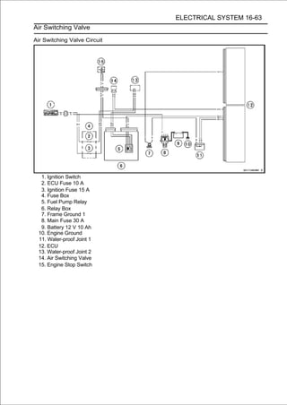
![16-64 ELECTRICAL SYSTEM
Radiator Fan System
Fan Motor Inspection
• Remove the air cleaner housing (see Air Cleaner Housing
Removal in the Fuel System (DFI) chapter).
•Slide the dust cover [A].
•Disconnect the connector [B].
• Using an auxiliary leads, supply battery power to the fan
motor.
If the fan does not rotate, the fan motor is defective and
must be replaced.
Radiator Fan Circuit
1. Ignition Switch 8. Battery 12 V 10 Ah
2. Fan Fuse 15 A 9. Engine Ground
3. Fuse Box 10. ECU
4. Fan Relay 11. Joint Connector 4
5. Relay Box 12. Water Temperature Sensor
6. Frame Ground 1 13. Joint Connector 3
7. Main Fuse 30 A 14. Fan Motor](https://image.slidesharecdn.com/2008-100321201635-phpapp01/85/2008-617-320.jpg)
![ELECTRICAL SYSTEM 16-65
Meter, Gauge, Indicator Unit
Meter Unit Removal/Installation
•Remove:
Windshield (see Windshield Removal in the Frame
chapter)
Wellnuts [A]
Quick Rivets [B]
○Push the central pin, and then remove the quick rivet.
• Remove the bolts [A] on both sides.
• Slide back the dust cover [A] and disconnect the meter
unit connector [B].
• Remove[B] and cover [A] and washers, and separate the
meter unit
the screws
[C].
CAUTION
Place the meter unit so that the face is up. If
ammeter unit is left upside down or sideways for
any length of time, it will malfunction.
• Tighten:
Torque - Meter Unit Mounting Screws: 1.2 N·m (0.12 kgf·m,
11 in·lb)
• Run thethe Appendix chapter). Wire, and Hose Routing
section in
lead correctly (see Cable,](https://image.slidesharecdn.com/2008-100321201635-phpapp01/85/2008-618-320.jpg)
![16-66 ELECTRICAL SYSTEM
Meter, Gauge, Indicator Unit
Meter Unit Disassembly
• Before disassembling the meter unit, be sure to read the
CAUTION below.
CAUTION
The anti-frosted agent is applied to the inside of the
lens [A] of the upper meter cover [B] for preventing
the lens condensation.
If the finger touches the inside of the lens, the anti
-frosted agent is wiped off, as a result, lens may be
misted. Likewise, do not clean the inside of the lens by
using the cloth, and so on.
CAUTION
As the LCD (Liquid Crystal Display) parts [A] of this
meter are frail for ultraviolet rays, the LCD parts
may have trouble when the parts are exposed to the
ultraviolet rays for long time with the parts disas-
sembled.
When replacing the meter cover, disassemble it at
the indoor not to expose LCD parts to the strong
ultraviolet rays and assemble it within one hour.
• Remove:
Meter Unit (see Meter Unit Removal/Installation)
Screws [A]
Lower Meter Cover [B]
• Separate the meter assembly [A] and upper meter cover
[B].](https://image.slidesharecdn.com/2008-100321201635-phpapp01/85/2008-619-320.jpg)
![ELECTRICAL SYSTEM 16-67
Meter, Gauge, Indicator Unit
Meter Unit Inspection
• Remove the meter unit [A] (see Meter Unit Removal).
[1] Ignition
[2] Fuel Level Warning Indicator Light (LED) (-) [3]
Stop Watch (+)
[4] Lap Time (+)
[5] Neutral Indicator Light (LED) (-)
[6] ECU Communication Signal
[7] Tachometer Signal
[8] Water Temperature Sensor (-)
[9] Unused
[10] Unused
[11] Ground (-)
[12] Battery (+)
[13] Warning Indicator Light (LED) (Oil Pressure Warning)
(-)
[14] Unused
[15] Right Turn Signal indicator Light (LED) (+)
[16] Left Turn Signal indicator Light (LED) (+) [17]
High Beam Indicator Light (LED) (+)
[18] Speed Sensor Signal
[19] Unused
[20] Unused
CAUTION
Do not drop the meter unit. Place the meter unit so
that it faces upward. If the meter assembly is left up-
side down or sideways for a long time or dropped,
it will malfunction. Do not short each terminals.
Liquid Crystal Display (LCD) Segments Check
• Using the insulated auxiliary leads, connect the 12 V battery
to the meter unit connector as follows.
○Connect the battery positive terminal to the terminal [12].
○Connect the battery negative terminal to the terminal [11].
• Connect the terminal [1] to the terminal [12].](https://image.slidesharecdn.com/2008-100321201635-phpapp01/85/2008-620-320.jpg)
![16-68 ELECTRICAL SYSTEM
Meter, Gauge, Indicator Unit
○When the terminals are connected, all the LCD segments [A]
appear for 3 seconds.
○The fuel level warning indicator light (LED) [B] goes on for 3
seconds.
If the LCD segments do not appear, replace the meter
unit.
• Disconnect the terminal [1].
○All the LCD segments disappear.
○For models equipped with an immobilizer system, the
warning indicator light (LED) [C] starts flashing (see
Abstract in the Immobilizer System (Equipped Models)
section).
If the segments do not disappear, replace the meter unit.
• Connect the terminal [1] to the terminal [12] again.
○About 5 seconds after, the fuel level warning indicator light
(LED) blinks [A] and the FUEL segments [B] appears in
the display.
○The FUEL segments is flashing.
If the fuel level warning indicator light (LED) does not blink
and/or the FUEL segments does not appear, replace the
meter unit.
NOTE
○This meter unit has a failure detection function (for open
or short) of the fuel reserve switch. When the fuel re-
serve switch is open or short, the meter unit alerts the
rider by the fuel level warning indicator light (LED) blinks
and the FUEL segments appears in the display.
○If the failure detection function operates with the meter unit
installed on the motorcycle, inspect the fuel reserve switch
(see Fuel Reserve Switch Inspection in the Electrical System
chapter) and wiring.
○About 10 seconds after, the warning indicator light (LED)
[A] blinks and the FI warning symbol [B] appears in the
display.
○The FI warning symbol is blinking.
If the warning indicator light (LED) does not blink and/or
the FI warning symbol does not appear, replace the meter
unit.
NOTE
○This meter unit has a failure detection function of the
ECU communication. When the ECU communication
error was detected, the meter unit alerts the rider by the
warning indicator light (LED) blinks and the FI warning
symbol appears in the display (see ECU Communica-
tion Line Inspection in the Fuel System (DFI) chapter).](https://image.slidesharecdn.com/2008-100321201635-phpapp01/85/2008-621-320.jpg)
![ELECTRICAL SYSTEM 16-69
Meter, Gauge, Indicator Unit
MODE AND RESET BUTTON Operation Check
• Connect the 12 V battery and terminals in the same man-
ner as specified in the "Liquid Crystal Display (LCD) Seg-
ments Check".
• Check that the display [B] change to the ODO, TRIP, and
CLOCK and STOP WATCH displays each time the MODE
button [A] is pressed.
○When the fuel level warning indicator light (LED) blinked,
display change to FUEL, ODO, TRIP, CLOCK and, STOP
WATCH and FUEL.
If the display function does not work, replace the meter
unit.
• Indicate the clock mode.
• pushedthat more than two seconds, the meter displaymode
is
Check
for
when the RESET button [A] in CLOCK
turns to the clock set mode.
○Both the hour and minute display start flashing.
• In the effect the HOUR setting mode, press the reset button
again to
HOUR/MINUTE
setting mode.
○The hour display flashes on the display.
• Press the MODE button to set the hour.
• In the HOUR setting mode, press the RESET button to
effect the MINUTE setting mode.
○The minute display flashes on the display.
• Press the MODE button to set the minute.](https://image.slidesharecdn.com/2008-100321201635-phpapp01/85/2008-622-320.jpg)
![16-70 ELECTRICAL SYSTEM
Meter, Gauge, Indicator Unit
• In the the HOUR/MINUTE setting mode. RESET button to
return to
MINUTE setting mode, press the
• Press the MODE button to complete the time setting
process.
• Indicate the ODO mode.
• Check °C, km and °F, km and °C display eachmile and °F,
Mile and
that the display [A] [B] change to the
time by
pushing the RESET bottom while MODE bottom pushed
in.
NOTE
○Mile/Km Display can alternate between English and
metric modes (mile and km) in the digital meter. Make
sure that km or mile according to local regulations is
correctly displayed before riding.
If the display function does not work and adjust, replace
the meter unit.
Speedometer Check
• Connect the 12 V battery and terminals in the same man-
ner as specified in the "Liquid Crystal Display (LCD) Seg-
ments Check".
• The speed equivalent to the input frequency is indicated in
the oscillator [A], if the square wave (illustrated as shown)
would be input into the terminal [18].
○Indicates approximately 65 km/h in case the input
frequency would be approximately 605 Hz.
○Indicates approximately 65 mph in case the input
frequency would be approximately 968 Hz.
If the speedometer does not work, replace the meter unit.
If the oscillator is not available, the speedometer can be
checked as follows.
○Connect the meter unit connector temporarily.
○Raise the rear wheel off the ground with the stand.
○Turn the ignition switch ON.
○Rotate the rear wheel by hand.
○Check that the speedometer shows the speed.
If the speedometer does not work, inspect the speed sensor
and wiring (see Speed Sensor Output Voltage Inspection in
the Fuel System (DFI) chapter).
If the speed sensor and wiring are normal, replace the
meter unit.](https://image.slidesharecdn.com/2008-100321201635-phpapp01/85/2008-623-320.jpg)
![ELECTRICAL SYSTEM 16-71
Meter, Gauge, Indicator Unit
Odometer Check
• Check the odometer with the speedometer check in the
same way.
If value indicated in the odometer is not added, replace
the meter unit.
NOTE
○The data is maintained even if the battery is discon-
nected.
○When the figures come to 999999, they are stopped and
locked.
Trip Meter Check
• Check the trip meter with the speedometer in the same
way.
If value indicated in the trip meter is not added, replace
the meter unit.
• Check that when the RESET button is pushed for more
than two seconds, the figure display turns to 0.0.
If the figure display does not indicate 0.0, replace the me-
ter unit.
Water Temperature Meter Check
• Connect the 12 V battery and terminals in the same man-
ner as specified in the "Liquid Crystal Display (LCD) Seg-
ments Check".
• Connect the variable rheostat [A] to the terminal [8] as
shown in the figure.
• Check that the number of segments matches the
resistance value of the variable rheostat.
Resistance Value
(Ω) Temperature Meter Warning Indicate
-- - [A]
209.8 50°C (122°F) - [B]
69.1 80°C (176°F) - [B]
25 116°C (241°F) Flash [C]
17 HI Flash [D]
If any display function does not work, replace the meter
unit.](https://image.slidesharecdn.com/2008-100321201635-phpapp01/85/2008-624-320.jpg)
![16-72 ELECTRICAL SYSTEM
Meter, Gauge, Indicator Unit
Tachometer Check
• Connect the 12 V battery and terminals in the same man-
ner as specified in the "Liquid Crystal Display (LCD) Seg-
ments Check".
○When the terminals are connected, the tachometer needle
momentary points to the last reading, and then return to the 0
position.
If the needle function does not work, replace the meter
unit.
• The revolutions per minute (rpm) equivalent to the input
frequency is indicated in the oscillator [A] if the square
wave (illustrated as shown in the figure) would be input
into the terminal [7].
○Indicates approximately 4 000 rpm in case the input
frequency would be approximately 133.3 Hz.
If the oscillator is not available, the tachometer can be
checked as follows.
○Connect the 12 V battery and terminals in the same manner
as specified in the "Liquid Crystal Display (LCD) Segments
Check".
○When the terminals are connected, the tachometer needle
momentary points to the last reading, and then return to the 0
position.
If the needle function does not work, replace the meter
unit.
○Using the insulated auxiliary lead, quickly open and con-
nect the terminal [1] to the terminal [7] repeatedly.
○Then the tachometer needle [A] should flick [B].
If the needle does not flick, replace the meter unit.](https://image.slidesharecdn.com/2008-100321201635-phpapp01/85/2008-625-320.jpg)
![ELECTRICAL SYSTEM 16-73
Meter, Gauge, Indicator Unit
Stop Watch Check
• Connect the 12 V battery and terminal in the same man-
ner as specified in the “Liquid Crystal Display (LCD) Seg-
ments Check”.
• Press the MODE button each time to set the stop watch
mode.
• Connect the insulated auxiliary lead processed insulation
to the terminal [3] as shown in the figure, then stop watch
start to count.
• While count the stop watch, connect the auxiliary lead to
the terminal [4] as shown in the figure, then indicate the
counted lap time during 10 seconds.
• Connect the variable rheostat [A] to the terminal [8] as
shown in the figure.
• When adjusting the resistance temperature (HI seg- lap
display segment indicate the water
to less than 21.1Ω,
ments).
○The HI segment is flashing.
If the display function does not work, replace the meter
unit.
Gear Position Indication Inspection
NOTE
○The gear position is indicated by the data sent from the
ECU.
○Be sure the ECU communication line is normal (see
ECU Communication Line Inspection in the Fuel System
(DFI) chapter).
○Inspect with the meter unit installed on the motorcycle.
• Set the gear position in the neutral position.
• Turn the ignition switch ON.
○The neutral indicator light (LED) [A] should go on.
○The gear position [B] does not appear in the display.
• Set the gear position in the 1st position.
○The 1 segments [A] should appear in the display.
○The neutral indicator light (LED) goes off.
• Raise the rear wheel off the ground with the stand.
• 6th in the engineorder (2nd → 3rd → 4th → 5th → from 2nd
to
Start
numerical
and change the gear position
6th).
○Check that the display corresponding to each gear position
appears.
• Turn the ignition switch OFF
If the display function does not work, inspect the gear
position switch (see Gear Position Switch Inspection) and
wiring.
If the gear position switch and wiring are normal, replace
the meter unit.](https://image.slidesharecdn.com/2008-100321201635-phpapp01/85/2008-626-320.jpg)
![16-74 ELECTRICAL SYSTEM
Meter, Gauge, Indicator Unit
Lights (LED) Inspection
Shift Up Indicator Light (LED) [A]
Fuel Level Warning Indicator Light (LED) [B]
Neutral Indicator Light (LED) [C]
Turn Signal Indicator Light (LED) [D]
High Beam Indicator Light (LED) [E]
Warning Indicator Light (LED) [F]
Illumination Light (LED) [G]
Illumination Light (LED) Inspection
• Connect the 12 V battery and terminals in the same man-
ner as specified in the “Liquid Crystal Display (LCD) Seg-
ments check.”
○When the terminals are connected, the illumination light
(LED) should go on.
If the illumination light (LED) does not go on, replace the
meter unit.
• Check whether the level of the illumination light (LED) can
be adjusted in 4 levels by pushing the RESET button each
time.
If the light level does not changes, replace the meter unit.
Neutral Indicator Light (LED) Inspection
• Connect the 12 V battery and terminals in the same man-
ner as specified in the “Liquid Crystal Display (LCD) Seg-
ments check.”
• Using the insulated auxiliary lead, 12 V battery to the meter
unit connector as follows.
○Connect the battery negative (-) terminal to the terminal
[5].
○When the terminals are connected, the neutral indicator
light (LED) should go on.
If the neutral indicator light (LED) does not go on, replace the
meter unit.
Warning Indicator Light (LED) (Oil Pressure Warning)
Inspection
• Connect the 12 V battery and terminals in the same man-
ner as specified in the “Liquid Crystal Display (LCD) Seg-
ments check.”
• Using the insulated auxiliary lead, 12 V battery to the meter
unit connector as follows.
○Connect the battery negative (-) terminal to the terminal
[13].](https://image.slidesharecdn.com/2008-100321201635-phpapp01/85/2008-627-320.jpg)
![ELECTRICAL SYSTEM 16-75
Meter, Gauge, Indicator Unit
○When the terminals are connected, the warning indicator
light (LED) [A] blinks and the oil pressure warning symbol [B]
appears in the display.
○The oil pressure warning symbol is blinking.
If the warning indicator light (LED) does not blink and/or
oil pressure warning symbol does not appear, replace the
meter unit.
Left and Right Turn Signal Indicator Light (LED)
• Connect the 12 V battery and terminals in the same man-
ner as specified in the “Liquid Crystal Display (LCD) Seg-
ments check.”
• Using the insulated auxiliary leads, 12 V battery to the
meter unit connector as follows.
○Connect the battery positive (+) terminal to the terminal
[15].
○Connect the battery positive (+) terminal to the terminal
[16].
○When the terminals are connected, the turn signal indicator
light (LED) should go on.
If the turn signal indicator light (LED) does not go on,
replace the meter unit.
High Beam Indicator Light (LED)
• Connect the 12 V battery and terminals in the same man-
ner as specified in the “Liquid Crystal Display (LCD) Seg-
ments check.”
• Using the insulated auxiliary lead, 12 V battery to the meter
unit connector as follows.
○Connect the battery positive (+) terminal to the terminal
[17].
○When the terminals are connected, the high beam indicator
light (LED) should go on.
If the turn signal high beam indicator light (LED) does not go
on, replace the meter unit.
Fuel Level Warning Indicator Light (LED)
• Connect the 12 V battery and terminals in the same man-
ner as specified in the “Liquid Crystal Display (LCD) Seg-
ments check.”
○When the terminals are connected, the fuel level warning
indicator light (LED) should go on for 3 seconds.
If the fuel level warning indicator light (LED) does not go on,
replace the meter unit.](https://image.slidesharecdn.com/2008-100321201635-phpapp01/85/2008-628-320.jpg)
![16-76 ELECTRICAL SYSTEM
Meter, Gauge, Indicator Unit
• Connect the variable rheostat [A] to the terminal [2] as
shown in the figure.
• Adjust the resistance value to the approximately 20 Ω.
○When the terminals are connected, the fuel level warning
indicator light (LED) [A] should go on and the FUEL segments
[B] appears in the display.
○The FUEL segments is flashing.
If the fuel level warning indicator light (LED) does not go on
and/or the FUEL segments does not appear, replace the
meter unit.
• Adjust the resistance value to the approximately 100 Ω.
○The fuel level warning indicator light (LED) goes off and
the FUEL segments disappears from the display.
If the fuel level warning indicator light (LED) does not go off
and/or the FUEL segments does not disappear, replace
the meter unit.
• Disconnect the terminal [2].
○About 5 seconds after, the fuel level warning indicator light
(LED) [A] blinks and the FUEL segments [B] appears in
the display.
○The FUEL segments is flashing.
If the fuel level warning indicator light (LED) does not blink
and/or the FUEL segments does not appear, replace the
meter unit.
• Connect the battery negative (-) terminal to the terminal
[2].
○When the terminal is connected, the fuel level warning
indicator light (LED) blinks and the FUEL segments flashes on
the display.
If the fuel level warning indicator light (LED) does not blink
and/or the FUEL segments does not displayed, replace the
meter unit.](https://image.slidesharecdn.com/2008-100321201635-phpapp01/85/2008-629-320.jpg)
![ELECTRICAL SYSTEM 16-77
Meter, Gauge, Indicator Unit
Shift Up Indicator Light (LED)
• Connect the 12 V battery and terminal in the same man-
ner as specified in the “Liquid Crystal Display (LCD) Seg-
ments Check”.
• The revolutions per minute (rpm) equivalent to the input
frequency is indicated in the oscillator [A] if the square
wave (illustrated as shown) would be input into the termi-
nal [7].
• When set the oscillator more than 446 Hz, shift up indicator
light (LED) go on.
If the shift up indicator light (LED) does not go on, replace the
meter unit.](https://image.slidesharecdn.com/2008-100321201635-phpapp01/85/2008-630-320.jpg)
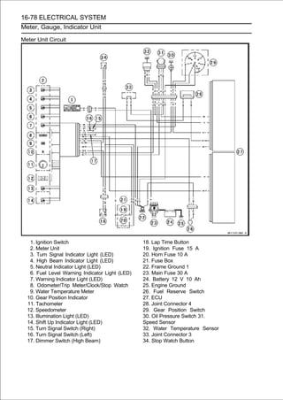
![ELECTRICAL SYSTEM 16-79
Immobilizer System (Equipped Models)
This motorcycle is equipped with an immobilizer system to protect the motorcycle from theft. This
system provides a theft proof device by means of matching a code between the inbuilt key transpon-
der and ECU. If the code does not match, ignition system, injectors, sub-throttle valve actuator and
exhaust butterfly valve actuator will not operate and the engine will not start.
Abstract
• Do not keep more than one immobilizer key of any system on a key ring. Jamming of the key code
signal may occur and the operation of the system may be affected.
• The warning indicator light (LED) will flash for a period of 24 hours once the ignition switch has been
switched off and the key removed. This flashing can be set to on or off as desired by holding the
MODE and RESET buttons down for 2 seconds within 20 seconds of switching the ignition off.
• If all coded keys (master key and user keys) are lost the ECU and ignition switch will have to be
replaced.
• The immobilizer system can not function until the master key code is registered in the ECU.
• AtotalofsixkeyscanberegisteredintheECUatanyonetime(onemasterkeyandfiveuserkeys).
• If the master key is lost it is not possible to register new user keys.
Operational Cautions
1. Do not put two keys of any immobilizer system on the same key ring.
2. Do not submerge any key in water.
3. Do not expose any key to excessively high temperature.
4. Do not place any key close to magnet.
5. Do not place a heavy item on any key.
6. Do not grind any key or alter its shape.
7. Do not disassemble the plastic part of any key.
8. Do not drop the key and/or apply any shocks to the key.
9. When a user key is lost, the user should go to his dealer to invalidate the lost key registration in
the ECU.
10.When the master key is lost, the user should go to his dealer and have a new ECU installed and
register a new master key and user keys.
NOTE
○No.9 and 10 are strongly recommended to the customer to ensure security of the motorcycle.
Key Registration
Case 1: When the user key has been lost or additional
spare user key is required.
• Prepare a new spare user key.
• Cut the key in accordance with the shape of the current
user key.
• Remove the center seat cover (see Seat Cover Removal in
the Frame).
• Disconnect the immobilizer/Kawasaki diagnostic system
connector [A].
• Connect the key registration unit [A].
Special Tool - Key Registration Unit: 57001-1582](https://image.slidesharecdn.com/2008-100321201635-phpapp01/85/2008-632-320.jpg)
![16-80 ELECTRICAL SYSTEM
Immobilizer System (Equipped Models)
• Insert the master key to the ignition switch and turn it ON.
Verified
○The warning indicator light (LED) and immobilizer warning
symbol [A] blinks to display the registration mode (go to the
next step).
Not Verified
○The warning indicator light (LED) and immobilizer warning
symbol [A] blinks to display the collation error (refer to the
following failure illustrations).
Immobilizer Amplifier Failure
Master Key Collation Error
• Turn the master key OFF and remove the master key.
○The warning indicator light (LED) [A] blinks continuously
to display that the ECU is in the registration mode for 15
seconds.
NOTE
○Insert next key and turn ON within 15 seconds after pre-
vious key is turned off and removed otherwise registra-
tion mode will be ended and the warning indicator light
(LED) stops flashing.
○To return to the registration mode start the master key
verification procedure. This applies to all user key reg-
istration.
• Insert the user key 1 to the ignition switch and turn it ON.
NOTE
○Keep the other user key away from the immobilizer an-
tenna.](https://image.slidesharecdn.com/2008-100321201635-phpapp01/85/2008-633-320.jpg)
![ELECTRICAL SYSTEM 16-81
Immobilizer System (Equipped Models)
○If there is any problem in the registration, the warning
indicator light (LED) and immobilizer warning symbol [A]
blinks to display the collation error.
Immobilizer Amplifier Failure
When Registered User Key is Inserted.
User Key Collation Error
• The user key 1 is successfully registered in the ECU.
○The warning indicator light (LED) and immobilizer warning
symbol [A] blinks 2 times and stops for 1 second and then
repeats this cycle.
• Turn the user key 1 OFF and remove the user key 1.
○The warning indicator light (LED) [A] blinks to display the
registration mode.
NOTE
○Turn off the ignition switch and wait for the period of 15
seconds or more. The registration mode automatically
finishes and the warning indicator light (LED) will switch
off.
○This procedure registered the master key and one user
key.
○Continue with the procedure to register the second and
later keys before the 15 seconds period has elapsed.
• Insert the user key 2 to the ignition switch and turn it ON.](https://image.slidesharecdn.com/2008-100321201635-phpapp01/85/2008-634-320.jpg)
![16-82 ELECTRICAL SYSTEM
Immobilizer System (Equipped Models)
○If there is any problem in the registration, the warning
indicator light and immobilizer warning symbol [A] blinks to
display the collation error.
Immobilizer Amplifier Failure
When Registered User Key is Inserted.
User Key Collation Error
• The user key 2 is registered in the ECU.
○The warning indicator light (LED) and immobilizer warning
symbol [A] blinks 3 times and stops for 1 second and then
repeats this cycle.
○This procedure has registered the master key and 2 user
keys.
• Continue with the procedure to register an additional 3
user keys.
NOTE
○The ECU can store up the six key codes (master key × 1
and user key × 5).
User Key Indicator Light and Symbol Flashes
Indicator
Light and Indicator
Symbol Light and Remarks
Blinks Symbol Stop
User Key 3 4 times 1 seconds Repeat
User Key 4 5 times 1 seconds Repeat
User Key 5 6 times 1 seconds Repeat
• Turn OFF the ignition switch and wait for period of more
than 15 seconds.
• The registration mode automatically ends.](https://image.slidesharecdn.com/2008-100321201635-phpapp01/85/2008-635-320.jpg)
![ELECTRICAL SYSTEM 16-83
Immobilizer System (Equipped Models)
• The warning indicator light (LED) goes off [A].
• Remove the keydiagnostic system connector.
immobilizer/Kawasaki
registration unit and connect the
NOTE
○Turn the ignition switch ON with the registered user key.
○Check that the engine can be started using all
registered user keys.](https://image.slidesharecdn.com/2008-100321201635-phpapp01/85/2008-636-320.jpg)
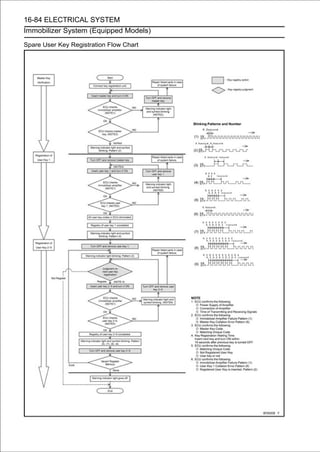
![ELECTRICAL SYSTEM 16-85
Immobilizer System (Equipped Models)
Case 2: When the ignition switch is faulty and to be
replaced.
• Prepare a new ignition switch [A] and two new user keys
[B].
○These parts are available as a set. Prepare the current
master key [C].
• Remove:
Ignition Switch and Immobilizer Antenna (see Immobi-
lizer System Parts Replacement)
Center Seat Cover (see Seat Cover Removal in the
Frame chapter)
• After removing the ignition switch and immobilizer an-
tenna, connect the inlet air temperature sensor connector
temporarily.
NOTE
○When the ignition switch is turned ON with inlet air tem-
perature sensor connector disconnected, the ECU de-
tects the service code 13 (see Self-diagnosis Outline in
the Fuel System (DFI) chapter).
• Disconnect
connector [A].
the immobilizer/Kawasaki diagnostic system
• Connect the key registration unit [A].
Special Tool - Key Registration Unit: 57001-1582
• Connect:
New Ignition Switch Lead Connector [A]
Immobilizer Antenna Lead Connector [B]](https://image.slidesharecdn.com/2008-100321201635-phpapp01/85/2008-638-320.jpg)
![16-86 ELECTRICAL SYSTEM
Immobilizer System (Equipped Models)
• Put the current master key [A] at the antenna [B].
NOTE
○Keep the antenna more than 15 cm (5.9 in.) from the
ignition switch.
• Insert the new user key 1 [C] to the new ignition switch [D]
and turn it ON.
Verified
○The warning indicator light (LED) and immobilizer warning
symbol [A] blinks to display the ECU is in the registration mode
(go to the next step).
Not Verified
○The warning indicator light (LED) and immobilizer warning
symbol [A] blinks to display the collation error.
Immobilizer Amplifier Failure
Master Key Collation Error
• Turn OFF and remove the new user key 1.
• Temporarily place the antenna [A] on the new ignition
switch [B].
• Insert it ON. key 1 [C] again into the new ignition switch
and turn
the user](https://image.slidesharecdn.com/2008-100321201635-phpapp01/85/2008-639-320.jpg)
![ELECTRICAL SYSTEM 16-87
Immobilizer System (Equipped Models)
NOTE
○Place the antenna on the ignition switch, insert the next
key and turn ON within 15 seconds after previous key
is turned off and removed otherwise registration mode
will be ended and the warning indicator light (LED) stops
flashing.
○To return to the registration mode start the master key
verification procedure. This applies to all user key reg-
istration.
○Keep other user keys away from the immobilizer an-
tenna.
○If there is any problem in the registration, the warning
indicator light (LED) and immobilizer warning symbol [A]
blinks to display the collation error.
Immobilizer Amplifier Failure
When Registered User Key is Inserted.
User Key Collation Error](https://image.slidesharecdn.com/2008-100321201635-phpapp01/85/2008-640-320.jpg)
![16-88 ELECTRICAL SYSTEM
Immobilizer System (Equipped Models)
• The user key 1 is successfully registered in the ECU.
○The warning indicator light (LED) and immobilizer warn-
ing symbol [A] blinks 2 times and stops for 1 second and
then repeats this cycle to indicate successful registering
of user key 1.
• Turn OFF and remove user key 1.
○The warning indicator light (LED) [A] blinks to display the
registration mode.
NOTE
○Turn off the ignition switch and wait for the period more
than 15 seconds. The registration mode automatically
ends and warning indicator light (LED) goes off.
○This procedure has , registered the master key and one
user key.
○Continue the procedure to program the second and
later keys.
• Insert the user key 2 to the ignition switch and turn it ON.
○If there is any problem in the registration, the warning
indicator light (LED) and immobilizer warning symbol [A]
blinks to display the collation error.
Immobilizer Amplifier Failure
When Registered User Key is Inserted.](https://image.slidesharecdn.com/2008-100321201635-phpapp01/85/2008-641-320.jpg)
![ELECTRICAL SYSTEM 16-89
Immobilizer System (Equipped Models)
User Key Collation Error
• The user key 2 is successfully registered in the ECU.
○The warning indicator light (LED) and immobilizer warning
symbol [A] blinks 3 times and stops for 1 second and then
repeat this cycle to indicate successful programming of
user key 2.
• Turn OFF the ignition switch and wait for period more than 15
seconds.
• The registration mode automatically ends.
• The warning indicator light (LED) goes off [A].
• Remove the keydiagnostic system connector.
immobilizer/Kawasaki
registration unit and connect the
NOTE
○Turn the ignition switch ON with the registered user key.
○Check that the engine can be started using all
registered user keys.
• Install the newParts Replacement).and
Immobilizer System
ignition switch antenna (see
Case 3: When the ECU is faulty and has to be replaced.
• Prepare a new ECU [A], current master key [B] and current
user keys [C].
NOTE
○The key registration unit is not required.](https://image.slidesharecdn.com/2008-100321201635-phpapp01/85/2008-642-320.jpg)
![16-90 ELECTRICAL SYSTEM
Immobilizer System (Equipped Models)
• Replace the ECU [A] (see ECU Removal/Installation in
the Fuel System (DFI) chapter).
• Insert the current master key into the ignition switch and
turn it ON.
○If there is any problem in the registration, the warning
indicator light and immobilizer warning symbol [A] blinks to
display the collation error.
Immobilizer Amplifier Failure
Master Key Collation Error
• The master key is registered in the ECU.
○The warning indicator light (LED) and immobilizer warning
symbol [A] blinks 1 time and stops for 1 second and the
repeats this cycle to indicate successful registration of the
master key.](https://image.slidesharecdn.com/2008-100321201635-phpapp01/85/2008-643-320.jpg)
![ELECTRICAL SYSTEM 16-91
Immobilizer System (Equipped Models)
• Turn OFF the master key and remove it.
○The warning indicator light (LED) [A] blinks to display the
registration mode.
NOTE
○Insert next key and turn ON within 15 seconds after pre-
vious key is turned off and removed otherwise registra-
tion mode will be ended and the warning indicator light
(LED) goes off.
○To return to the registration mode start the master key
verification procedure. This applies to all user key reg-
istration.
• Insert the user key 1 to the ignition switch and turn it ON.
NOTE
○Keep the other user keys away from the immobilizer
antenna.
○If there is any problem in the registration, the warning
indicator light (LED) and immobilizer warning symbol [A]
blinks to display the collation error.
Immobilizer Amplifier Failure
When Registered User Key is Inserted.
User Key Collation Error](https://image.slidesharecdn.com/2008-100321201635-phpapp01/85/2008-644-320.jpg)
![16-92 ELECTRICAL SYSTEM
Immobilizer System (Equipped Models)
• The user key 1 is registered in the ECU.
○The warning indicator light (LED) and immobilizer warn-
ing symbol [A] blinks 2 times and stops for 1 second and
then repeats this cycle to indicate successful registration
of user key.
• Turn OFF and remove the user key 1.
○The warning indicator light (LED) [A] blinks to display the
registration mode codes.
NOTE
○Insert next key and turn ON within 15 seconds after pre-
vious key is turned off and removed otherwise registra-
tion mode will be ended and the warning indicator light
goes off.
○To return to the registration mode start the master key
verification procedure. This applies to all user key reg-
istration.
• Insert the user key 2 to the ignition switch and turn it ON.
○If there is any problem in the registration, the warning
indicator light (LED) and immobilizer warning symbol [A]
blinks to display the collation error code.
Immobilizer Amplifier Failure
When Registered User Key is Inserted.](https://image.slidesharecdn.com/2008-100321201635-phpapp01/85/2008-645-320.jpg)
![ELECTRICAL SYSTEM 16-93
Immobilizer System (Equipped Models)
User Key Collation Error
• The user key 2 is registered in the ECU.
○The warning indicator light (LED) and immobilizer warn-
ing symbol [A] blinks 3 times and stops for 1 second and
then repeats this cycle to indicate successful registration
of user key 2.
• Turn OFF the ignition switch and wait for period more than 15
seconds.
• The registration mode automatically ends.
• The warning indicator light (LED) goes off [A].
NOTE
○Turn the ignition switch ON with the registered user key.
○Check that the engine can be started using all
registered user keys.
Case 4: When master key is faulty or lost.
The master key replacement is considered very rare case.
However if it is required, the following is necessary.
NOTE
○The ECU must be replaced with a new one because the
master key code that is registered in the current ECU can
not be rewritten.](https://image.slidesharecdn.com/2008-100321201635-phpapp01/85/2008-646-320.jpg)
![16-94 ELECTRICAL SYSTEM
Immobilizer System (Equipped Models)
• Prepare[C].new ECU [A], new master key [B] and current
user keys
a
NOTE
○The key registration unit is not required.
○The key registration process is same as the electric control
unit replacement.
Case 5: When replacing the antenna.
• Prepare a new antenna.
• Refer to the Immobilizer System Parts Replacement.
NOTE
○The key registration is not required.](https://image.slidesharecdn.com/2008-100321201635-phpapp01/85/2008-647-320.jpg)
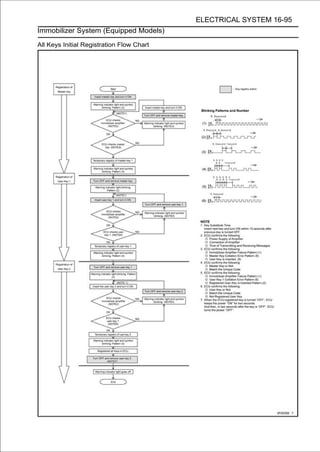
![16-96 ELECTRICAL SYSTEM
Immobilizer System (Equipped Models)
Immobilizer System Parts Replacement
Immobilizer Antenna
• Remove the right upper inner fairing (see Upper Inner Faring
Removal in the Frame chapter).
• Disconnect the lead connectors [A].
• Remove:
Middle Air Cleaner Housing (see Air Cleaner Housing
Removal in the Fuel System (DFI) chapter)
Steering Stem Head (see Stem, Stem Bearing Removal in
the Steering chapter)
Handlebars (see Handlebar Removal in the Steering
chapter)
• Using a small chisel or punch, turn out the Torx bolts [A].
• Remove the clamp [B].
• Pull out thethe steering stemtogether with the immobilizer
antenna from
ignition switch
head.
• Cut the band [A] and tape [B].
• Remove:
Rubber Damper [C]
Screws [D]
• Remove the antenna [E] together with the cover [F].
○Pull the lower parts [G] of the cover outside to clear the
projections [H] of the ignition switch.
• Install the rubber damper[C] ofon the immobilizer antenna
[B] so that the stepped side
[A]
the projections faces
upward.
○Fit the projections into the grooves [D].
• Install the clamp.
• Tighten a new TORX bolt [A] until the bolt head [B] is
broken [C].
• Run thethe Appendix chapter). Wire, and Hose Routing
section in
leads correctly (see Cable,](https://image.slidesharecdn.com/2008-100321201635-phpapp01/85/2008-649-320.jpg)
![ELECTRICAL SYSTEM 16-97
Immobilizer System (Equipped Models)
Immobilizer Amplifier Replacement
• Remove the right upper inner fairing (see Upper Inner
Fairing Removal in the Frame chapter).
• Disconnect the connector [A].
• Pull out the immobilizer amplifier [B] together with the rubber
protector [C] from the bracket [D].
ECU Replacement
• Refer to the ECU Removal/Installation in the Fuel System
(DFI) chapter.
Immobilizer Relational Parts Replacement Chart
Failed or Lost Part
Master User
Key Key Ignition An- Ampli-
ECU
(Red) (Black) Switch tenna fier
Master
Key
(Red) •
User
Key
• ○
(Black)
* Ignition
Switch •
An-
tenna •
Ampli-
fier •
ECU ○ •
* Replacement Part
• Main Replacement Part
○ Additional Replacement Part
Immobilizer System Inspection
• Refer to the Immobilizer Amplifier and Blank Key Detection
section in Fuel System (DFI) chapter.](https://image.slidesharecdn.com/2008-100321201635-phpapp01/85/2008-650-320.jpg)
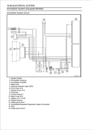
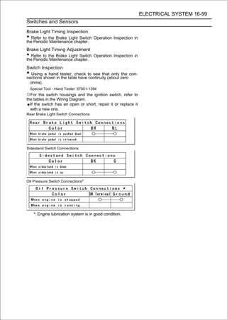
![16-100 ELECTRICAL SYSTEM
Switches and Sensors
Water Temperature Sensor Inspection
• Remove the water temperature sensor (see Water Tem-
perature Sensor Removal/Installation in the Fuel System
(DFI) chapter).
• Suspend the sensor [A] in a container of coolant so that
the threaded portion is submerged.
• Suspend an accurate thermometer [B] with temperature
sensing portions [C] located in almost the same depth.
NOTE
○The sensor and thermometer must not touch the
container side or bottom.
• Place the temperatureover a coolant while stirring the
ally raise
the container
of the
source of heat and gradu-
coolant gently.
• Using the hand tester, measure the internal resistance of
the sensor.
Special Tool - Hand Tester: 57001-1394
○The sensor sends electric signals to the ECU and water
temperature meter in the meter unit.
○Measure the resistance across the terminals and the body
(for the gauge) at the temperatures shown in the table.
If the hand tester does not show the specified values, re-
place the sensor.
Water Temperature Sensor
Resistance for ECU [D]
Temperature Resistance (kΩ)
(Terminal [1]-[3])
20°C (68°F) 2.46 +0.155
-0.143
80°C (176°F) 0.32 ±0.011
110°C (230°F) 0.1426 ±0.0041
Resistance for Water Temperature Gauge [E]
Temperature Resistance (Ω)
(Terminal [2]-Body)
50°C (122°F) 210 ±40
120°C (248°F) 21.2 ±1.5
Speed Sensor Removal
• Drain the coolant (see Coolant Change in the Periodic
Maintenance chapter).
•Remove:
Engine Sprocket Cover (see Engine Sprocket Removal
in the Final Drive chapter)
Water Hose [A]](https://image.slidesharecdn.com/2008-100321201635-phpapp01/85/2008-653-320.jpg)
![ELECTRICAL SYSTEM 16-101
Switches and Sensors
• Disconnect the connector [A].
• Remove:
Bolt [A]
Speed Senor [B]
Speed Sensor Installation
•Apply grease to the O-ring [A].
•Set the speed sensor bolt [B].
•Tighten:
Torque - Speed Sensor Bolt: 10 N·m (1.0 kgf·m, 89 in·lb)
• Install the removed parts (see appropriate chapters).
Speed Sensor Inspection
• Refer to the Speed Sensor Output Voltage Inspection in
the Fuel System (DFI) chapter.
Fuel Reserve Switch Inspection
• Fill the fuel tank with fuel and close the fuel tank cap.
• Remove the right side cover (see Side Cover Removal in
the Frame chapter).
• Disconnect the fuel pump lead connector [A].](https://image.slidesharecdn.com/2008-100321201635-phpapp01/85/2008-654-320.jpg)
![16-102 ELECTRICAL SYSTEM
Switches and Sensors
• Connect and the 12 V battery [B]Vto3.4 W bulb in a socket
with leads)
the test light [A] (12
the fuel pump lead
connector [C].
Connections:
Battery (+) → 12 V 3.4 W Bulb (One Side)
12 V 3.4 W Bulb (Other Side) → R/BK lead [D]
Battery (-) → BK/W lead [E]
If the test light turn on, the reserve switch is defective.
Replace the fuel pump.
• Draw the fuel(see Fuel Tankfuel tank with a Fuel Sys-
available pump
out from the
Removal in the
commercially
tem (DFI) chapter).
• Connect the test light (12 V 3.4 W bulb in a socket with
leads) and the 12 V battery to the fuel pump lead connec-
tor in the same way again.
Connections:
Battery (+) → 12 V 3.4 W Bulb (One Side)
12 V 3.4 W Bulb (Other Side) → R/BK lead
Battery (-) → BK/W lead
If the test light does not light, replace the fuel pump.
NOTE
○It may take a long time to turn on the test light in case
that the fuel reserve switch is inspected just after the
fuel is drawn. Leave the fuel pump lead connector with
leads for inspection connected for few minutes.
Oxygen Sensor Removal (Equipped Models)
•Disconnect:
Oxygen Sensor #1 Lead Connector (Gray) [A]
Oxygen Sensor #2 Lead Connector (Black) [B]
• Open the clamp [A] and free the leads.](https://image.slidesharecdn.com/2008-100321201635-phpapp01/85/2008-655-320.jpg)
![ELECTRICAL SYSTEM 16-103
Switches and Sensors
• Remove the oxygen sensor #1 [A].
• Remove:
Exhaust Manifold (see Exhaust Manifold Removal in the
Engine Top End chapter)
Oxygen Sensor #2 [A]
Oxygen Sensor Installation (Equipped Models)
CAUTION
Never drop the oxygen sensor [A], especially on a
hard surface. Such a shock to the unit can damage it.
Do not touch the sensing part [B] to prevent oil
contact. Oil contamination from hands can reduce
sensor performance.
• Tighten:
Torque - Oxygen Sensors: 25 N·m (2.5 kgf·m, 18 ft·lb)
• Run theRouting section inleadsAppendix chapter). Wire,
and Hose
oxygen sensor
the
correctly (see Cable,
Oxygen Sensor Inspection (Equipped Models)
• Refer to the Oxygen Sensor #1/#2 Inspection in the Fuel
System (DFI) chapter.
Oxygen Sensor Heater Inspection (Equipped
Models)
• Refer to the Oxygen Sensor Heater Inspection in the Fuel
System (DFI) chapter.
Gear Position Switch Removal
• Remove:
Lower Fairings (see Lower Fairing Removal in the Frame
chapter)
Fuel Tank (see Fuel Tank Removal in the Fuel System
(DFI) chapter)
Water Pump (see Water Pump Removal in the Cooling
System chapter)
• Slide out the rubber boot [A].
• Loosen the oil pressure switch terminal bolt [B], and
remove the switch lead [C].](https://image.slidesharecdn.com/2008-100321201635-phpapp01/85/2008-656-320.jpg)
![16-104 ELECTRICAL SYSTEM
Switches and Sensors
• Disconnect:
Water Temperature Sensor Connector [A]
Engine Subharness #1 Connector [B]
• Disconnect the speed sensor connector [A].
• Remove:
Screws [A]
Gear Position Switch [B]
• Remove the pins [A] and springs from the shift drum.
Gear Position Switch Installation
• Securely place the springs [A] and pins [B] into the holes [C]
of the shift drum.
• Apply grease to the new O-ring [D].
• Apply a non-permanent locking agent to the threads of
the gear position switch screws.
• Tighten:
Torque - Gear Position Switch Screws: 3.0 N·m (0.30 kgf·m,
27 in·lb)
• Run thethe Appendix chapter). Wire, and Hose Routing
section in
leads correctly (see Cable,
• Install the removed parts (see appropriate chapters).](https://image.slidesharecdn.com/2008-100321201635-phpapp01/85/2008-657-320.jpg)
![ELECTRICAL SYSTEM 16-105
Switches and Sensors
Gear Position Switch Inspection
NOTE
○Be sure the transmission and external shift mechanism
are good condition.
• Remove the fuel tank (see Fuel Tank Removal in the Fuel
System (DFI) chapter).
• Disconnect the engine subharness #1 connector [A].
• Set the hand tester [A] to thethe1engine subharness
and connect it to the terminals in
× kΩ or × 100 Ω range
#1 connector [B] and ground.
○When changing the gear position from lower gear to
higher gear, raise the rear wheel off the ground with the
stand and rotate the rear wheel by hand.
[C] Internal Circuit
[1] LG Lead
[2] G/R Lead
[3] BK Lead
Special Tool - Hand Tester: 57001-1394
Gear Position Switch Resistance (Unit: kΩ)
Connections
Gear
Position [1]-Ground [2]-Ground [3]-Ground
Neutral about 0 8.64 ∼ 9.54 about 0
1st - 2.22 ∼ 2.46 about 0
2nd - 1.42 ∼ 1.58 about 0
3rd - 0.954 ∼ 1.055 about 0
4th - 0.643 ∼ 0.711 about 0
5th - 0.410 ∼ 0.453 about 0
6th - 0.241 ∼ 0.266 about 0
If the tester reading is not as specified, replace the gear
position switch with a new one.](https://image.slidesharecdn.com/2008-100321201635-phpapp01/85/2008-658-320.jpg)
![16-106 ELECTRICAL SYSTEM
Relay Box
Relay Box Removal
• Remove the center seat cover (see Seat Cover Removal in
the Frame chapter).
• Disconnect the connectors [A].
• Pull out the relay box [B] from the rubber protector [C].
NOTE
○The relay box has relays and diodes. The relays and
diodes can not be removed.
Relay Circuit Inspection
NOTE
○The ECU main relay function is included in the ECU.
• Remove the relay box (see Relay Box Removal).
• Check conductivity of the and one 12numbered to the
by connecting the hand tester
following
V battery
terminals
relay box as shown in the figure (see Relay Box Internal
Circuit).
If the tester does not read as specified, replace the relay
box.
Relay Circuit Inspection (with the battery disconnected)
Tester Connection Tester Reading (Ω)
Headlight Relay 1-3 ∞
4-5 ∞
Fuel Pump Relay
6-7 Not ∞*
8-13 ∞
Starter Circuit Relay
8-9 ∞
14-17 ∞
Fan Relay
15-16 Not ∞*
*: The actual reading varies with the hand tester used.
Relay Circuit Inspection (with the battery connected)
Battery
Connection Tester Tester
(+) (-) Connection Reading (Ω)
Fuel Pump
Relay 6-7 4-5 0
Fan Relay 15-16 14-17 0
Battery
Connection Tester Connection Tester
(+) (-) DC 25 V Range Reading (V)
Starter Circuit Battery
Relay 13-9 8-9
Voltage
(+): Apply positive lead.](https://image.slidesharecdn.com/2008-100321201635-phpapp01/85/2008-659-320.jpg)

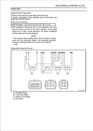
![16-108 ELECTRICAL SYSTEM
Fuse
30 A Main Fuse Removal
• Remove the fuel tank (see Fuel Tank Removal in the Fuel
System (DFI) chapter).
• Pull out the starter relay [A] from the bracket on the frame.
• Disconnect the connector [A].
• Pullpliers.the main fuse [A] from the starter relay with needle
nose
out
Fuse Box Fuse Removal
• Remove the front seat (see Front Seat Removal in the
Frame chapter).
• Push the hook [A] to lift up the lid [B].
• Pullpliers.fuses [A] straight out of the fuse box with needle
nose
the](https://image.slidesharecdn.com/2008-100321201635-phpapp01/85/2008-662-320.jpg)
![ELECTRICAL SYSTEM 16-109
Fuse
10 A ECU Fuse Removal
• Remove the front seat (see Front Seat Removal in the
Frame chapter).
• Pull the hook [A] to lift up the lid [B].
• Pull the ECU fuse [A] straight out of the fuse box with
needle nose pliers.
Fuse Installation
If a fuse fails during operation, inspect the electrical system
to determine the cause, and then replace it with a new
fuse of proper amperage.
• Install the fuse box fuses on the original position as specified
on the lid.
Fuse Inspection
•Remove the fuse.
•Inspect the fuse element.
If it is blown out, replace the fuse. Before replacing a
blown fuse, always check the amperage in the affected
circuit. If the amperage is equal to or greater than the
fuse rating, check the wiring and related components for
a short circuit.
Housing [A]
Fuse Element [B]
Terminals [C]
Blown Element [D]
NOTE
○If a mass current flows to the battery which needs
refreshing charge when the engine is turned, the main
fuse may be blown out.
CAUTION
When replacing a fuse, be sure the new fuse
matches the specified fuse rating for that circuit.
Installation of a fuse with a higher rating may cause
damage to wiring and components.](https://image.slidesharecdn.com/2008-100321201635-phpapp01/85/2008-663-320.jpg)