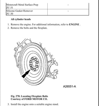
SlideShare a Scribd company logo
All cylinder heads
1. Remove the engine. For additional information, refer to ENGINE .
2. Remove the bolts and the flexplate.
Fig. 278: Locating Flexplate Bolts
Courtesy of FORD MOTOR CO.
3. Install the engine onto a suitable engine stand.
Motorcraft Metal Surface Prep
ZC-31
-
Silicone Gasket Remover
ZC-30
-
2006 Ford Expedition
2006 ENGINE Engine - Expedition & Navigator
me
Friday, April 17, 2009 11:09:52 PM Page 225 © 2005 Mitchell Repair Information Company, LLC.
4. Remove the special tool.
Fig. 279: Identifying Special Tool (303-F047)
Courtesy of FORD MOTOR CO.
5. Remove the 3 bolts and the RH engine support insulator.
Fig. 280: Identifying RH Engine Support Insulator Bolts
Courtesy of FORD MOTOR CO.
Fig. 281: Locating Cylinder Block Drain Plug
Courtesy of FORD MOTOR CO.
NOTE: LH shown, RH similar.
2006 Ford Expedition
2006 ENGINE Engine - Expedition & Navigator
me
Friday, April 17, 2009 11:09:52 PM Page 226 © 2005 Mitchell Repair Information Company, LLC.
6. Remove the cylinder block drain plugs and drain the coolant into a suitable
container.
7. Install the cylinder block drain plugs.
Tighten to 24 N.m (18 lb-ft).
Fig. 282: Locating Cylinder Block Drain Plug
Courtesy of FORD MOTOR CO.
8. Disconnect the RH camshaft position (CMP) sensor electrical connector.
Fig. 283: Identifying RH CMP Sensor Electrical Connector
Courtesy of FORD MOTOR CO.
9. Remove the stud bolt and the RH radio ignition interference capacitor.
NOTE: LH shown, RH similar.
2006 Ford Expedition
2006 ENGINE Engine - Expedition & Navigator
me
Friday, April 17, 2009 11:09:52 PM Page 227 © 2005 Mitchell Repair Information Company, LLC.
Fig. 284: Identifying RH Radio Ignition Interference Capacitor Stud Bolt
Courtesy of FORD MOTOR CO.
10. Disconnect the RH variable camshaft timing (VCT) solenoid electrical
connector.
Fig. 285: Locating Camshaft Timing (VCT) Solenoid Electrical
Connectors
Courtesy of FORD MOTOR CO.
11. Disconnect the 2 engine wiring harness retainers from the RH valve cover
studs.
Fig. 286: Locating Engine Wiring Harness Retainers At RH Valve Cover
2006 Ford Expedition
2006 ENGINE Engine - Expedition & Navigator
me
Friday, April 17, 2009 11:09:52 PM Page 228 © 2005 Mitchell Repair Information Company, LLC.
Courtesy of FORD MOTOR CO.
12. Disconnect the electrical connector retainer from the coolant tube.
Fig. 287: Locating Electrical Connector Retainer At Coolant Tube
Support Bracket
Courtesy of FORD MOTOR CO.
13. Disconnect the 4 RH ignition coil electrical connectors.
Fig. 288: Locating Ignition Coil Electrical Connectors
Courtesy of FORD MOTOR CO.
14. Disconnect the cylinder head temperature (CHT) sensor electrical connector.
2006 Ford Expedition
2006 ENGINE Engine - Expedition & Navigator
me
Friday, April 17, 2009 11:09:52 PM Page 229 © 2005 Mitchell Repair Information Company, LLC.
Fig. 289: Locating Cylinder Head Temperature (CHT) Sensor Electrical
Connector
Courtesy of FORD MOTOR CO.
15. Remove the stud bolt and the LH radio ignition interference capacitor.
Fig. 290: Identifying LH Radio Ignition Interference Capacitor And Stud
Bolt
Courtesy of FORD MOTOR CO.
Fig. 291: Identifying Ignition Coils And Bolts
Courtesy of FORD MOTOR CO.
NOTE: LH shown, RH similar.
2006 Ford Expedition
2006 ENGINE Engine - Expedition & Navigator
me
Friday, April 17, 2009 11:09:52 PM Page 230 © 2005 Mitchell Repair Information Company, LLC.
16. Remove the 8 bolts and the 8 ignition coils.
17. Remove the engine wiring harness from the engine assembly.
18. Remove the bolt and the oil level indicator tube.
Discard the O-ring seal.
Fig. 292: Locating Oil Level Indicator Tube Bolt
Courtesy of FORD MOTOR CO.
19. Remove the bolt and the RH CMP sensor.
Fig. 293: Locating Camshaft (CMP) Sensor Bolt
Courtesy of FORD MOTOR CO.
20. Remove the bolt and the LH CMP sensor.
2006 Ford Expedition
2006 ENGINE Engine - Expedition & Navigator
me
Friday, April 17, 2009 11:09:52 PM Page 231 © 2005 Mitchell Repair Information Company, LLC.
Fig. 294: Locating Bolt And LH CMP Sensor
Courtesy of FORD MOTOR CO.
21. Remove the bolt and the CKP sensor.
Fig. 295: Locating Crankshaft Position (CKP) Sensor Bolt
Courtesy of FORD MOTOR CO.
CAUTION: Do not use metal scrapers, wire brushes,
power abrasive discs or other abrasive
means to clean the sealing surfaces. These
tools cause scratches and gouges which
make leak paths. Use a plastic scraping tool
to remove all traces of old sealant.
When removing the valve cover, make sure to
avoid damaging the VCT solenoid.
NOTE: The fasteners are part of the valve cover and should
not be removed.
LH shown, RH similar.
2006 Ford Expedition
2006 ENGINE Engine - Expedition & Navigator
me
Friday, April 17, 2009 11:09:52 PM Page 232 © 2005 Mitchell Repair Information Company, LLC.
22. Loosen the fasteners and remove the valve covers.
Clean the valve cover mating surface of the cylinder head with silicone
gasket remover and metal surface prep. Follow the directions on the
packaging.
Inspect the valve cover gasket. If the gasket is damaged, remove and
discard the gasket. Clean the valve cover gasket groove with soap and
water or a suitable solvent.
Fig. 296: Locating Valve Cover Bolts
Courtesy of FORD MOTOR CO.
23. Remove the bolts, the coolant pump pulley and the 3 accessory drive belt idler
pulleys.
Fig. 297: Locating Coolant Pump Pulley And Accessory Drive Belt Idler
Pulley Bolts
Courtesy of FORD MOTOR CO.
24. Remove the bolts and the accessory drive belt tensioner.
2006 Ford Expedition
2006 ENGINE Engine - Expedition & Navigator
me
Friday, April 17, 2009 11:09:52 PM Page 233 © 2005 Mitchell Repair Information Company, LLC.
Fig. 298: Identifying Accessory Drive Belt Tensioner Bolts
Courtesy of FORD MOTOR CO.
25. Remove and discard the crankshaft pulley bolt. Using the special tool, remove
the crankshaft pulley.
Fig. 299: Removing Crankshaft Pulley Using Special Tool
Courtesy of FORD MOTOR CO.
26. Using the special tool, remove and discard the crankshaft front seal.
Fig. 300: Removing Crankshaft Front Seal Using Special Tool
Courtesy of FORD MOTOR CO.
2006 Ford Expedition
2006 ENGINE Engine - Expedition & Navigator
me
Friday, April 17, 2009 11:09:52 PM Page 234 © 2005 Mitchell Repair Information Company, LLC.
27. Remove the front 4 oil pan bolts.
Fig. 301: Locating Oil Pan Bolts-To-Front Cover
Courtesy of FORD MOTOR CO.
Fig. 302: Locating Cylinder Block Fasteners
Courtesy of FORD MOTOR CO.
NOTE: Correct fastener location is essential for assembly
procedure. Record fastener location.
2006 Ford Expedition
2006 ENGINE Engine - Expedition & Navigator
me
Friday, April 17, 2009 11:09:52 PM Page 235 © 2005 Mitchell Repair Information Company, LLC.
28. Remove the fasteners.
29. Remove the engine front cover from the cylinder block.
Fig. 303: Locating Engine Front Cover
Courtesy of FORD MOTOR CO.
30. Remove the crankshaft sensor ring from the crankshaft.
Fig. 304: View Of Crankshaft Sensor Ring At Crankshaft
Courtesy of FORD MOTOR CO.
2006 Ford Expedition
2006 ENGINE Engine - Expedition & Navigator
me
Friday, April 17, 2009 11:09:52 PM Page 236 © 2005 Mitchell Repair Information Company, LLC.
31. Position the crankshaft keyway at the 12 o'clock position.
Fig. 305: Positioning Crankshaft Keyway At 12 O'Clock Position
Courtesy of FORD MOTOR CO.
Fig. 306: Identifying Camshaft Lobe Position
Courtesy of FORD MOTOR CO.
32. The No. 1 cylinder camshaft exhaust lobe must be coming up on the exhaust
stroke. Verify by noting the position of the 2 intake camshaft lobes and the
exhaust lobe on the No. 1 cylinder.
NOTE: If the camshaft lobes are not exactly positioned as
shown in Fig. 306, the crankshaft will require one full
additional rotation to 12 o'clock.
CAUTION: If the components are to be reinstalled, they
must be installed in the same positions. Mark the
components for installation into the original
locations.
2006 Ford Expedition
2006 ENGINE Engine - Expedition & Navigator
me
Friday, April 17, 2009 11:09:52 PM Page 237 © 2005 Mitchell Repair Information Company, LLC.
Fig. 307: Identifying RH Cylinder Head Camshaft Roller Followers And
Bolts
Courtesy of FORD MOTOR CO.
33. Remove only the 3 camshaft roller followers shown in Fig. 307 from the RH
cylinder head.
CAUTION: Do not allow the valve keepers to fall off the
valve or the valve may drop into the cylinder.
NOTE: It may be necessary to push the valve down while
compressing the spring.
2006 Ford Expedition
2006 ENGINE Engine - Expedition & Navigator
me
Friday, April 17, 2009 11:09:52 PM Page 238 © 2005 Mitchell Repair Information Company, LLC.
Fig. 308: Identifying Special Tool For Removing/Installing Camshaft
Roller Followers
Courtesy of FORD MOTOR CO.
34. Using the special tool, remove the 3 designated camshaft roller followers in the
previous step from the RH cylinder head.
Fig. 309: Locating LH Cylinder Head Camshaft Roller Followers And
Bolts
Courtesy of FORD MOTOR CO.
35. Remove only the 3 camshaft roller followers shown in Fig. 309 from the LH
cylinder head.
CAUTION: If the components are to be reinstalled, they
must be installed in the same positions. Mark the
components for installation into the original
locations.
CAUTION: Do not allow the valve keepers to fall off the
2006 Ford Expedition
2006 ENGINE Engine - Expedition & Navigator
me
Friday, April 17, 2009 11:09:52 PM Page 239 © 2005 Mitchell Repair Information Company, LLC.
Fig. 310: Compressing Spring Using Special Tool
Courtesy of FORD MOTOR CO.
36. Using the special tool, remove the 3 designated camshaft roller followers in the
previous step from the LH cylinder head.
valve or the valve may drop into the cylinder.
NOTE: It may be necessary to push the valve down while
compressing the spring.
CAUTION: The crankshaft cannot be moved past the 6
o'clock position once set.
2006 Ford Expedition
2006 ENGINE Engine - Expedition & Navigator
me
Friday, April 17, 2009 11:09:52 PM Page 240 © 2005 Mitchell Repair Information Company, LLC.
Fig. 311: Identifying Crankshaft Keyway Position
Courtesy of FORD MOTOR CO.
37. Rotate the crankshaft clockwise and position the crankshaft keyway at the 6
o'clock position.
Fig. 312: Identifying LH Timing Chain Tensioner & Tensioner Arm
Courtesy of FORD MOTOR CO.
38. Remove the bolts, the LH timing chain tensioner and tensioner arm.
CAUTION: If one or both of the tensioner mounting bolts are
loosened or removed, the tensioner-sealing bead
must be inspected for seal integrity. If cracks,
tears, separation from the tensioner body or
permanent compression of the seal bead is
observed, install a new tensioner.
CAUTION: If one or both of the tensioner mounting bolts are
loosened or removed, the tensioner-sealing bead
2006 Ford Expedition
2006 ENGINE Engine - Expedition & Navigator
me
Friday, April 17, 2009 11:09:52 PM Page 241 © 2005 Mitchell Repair Information Company, LLC.
Fig. 313: Identifying RH Timing Chain Tensioner, Tensioner Arm And
Bolts
Courtesy of FORD MOTOR CO.
39. Remove the bolts, the RH timing chain tensioner and tensioner arm.
40. Remove the RH and LH timing chains and the crankshaft sprocket.
Remove the RH timing chain from the camshaft sprocket.
Remove the RH timing chain from the crankshaft sprocket.
Remove the LH timing chain from the camshaft sprocket.
Remove the LH timing chain and crankshaft sprocket.
must be inspected for seal integrity. If cracks,
tears, separation from the tensioner body or
permanent compression of the seal bead is
observed, install a new tensioner.
2006 Ford Expedition
2006 ENGINE Engine - Expedition & Navigator
me
Friday, April 17, 2009 11:09:52 PM Page 242 © 2005 Mitchell Repair Information Company, LLC.
Fig. 314: Identifying RH/LH Timing Chains
Courtesy of FORD MOTOR CO.
41. Remove the LH and RH timing chain guides.
Remove the bolts.
Remove both timing chain guides.
Fig. 315: Identifying Timing Chain Guide And Mounting Bolts
Courtesy of FORD MOTOR CO.
NOTE: RH shown, LH similar.
2006 Ford Expedition
2006 ENGINE Engine - Expedition & Navigator
me
Friday, April 17, 2009 11:09:52 PM Page 243 © 2005 Mitchell Repair Information Company, LLC.
42. Using the special tool, remove the bolt and the RH VCT phaser sprocket
assembly.
Discard the camshaft phaser sprocket bolt.
Fig. 316: Identifying VCT Phaser Sprocket Bolt And Holder Tool
Courtesy of FORD MOTOR CO.
43. Using the special tool, remove the bolt and the LH VCT phaser sprocket
assembly.
Discard the camshaft phaser sprocket bolt.
CAUTION: Damage to the VCT phaser sprocket
assembly will occur if mishandled or used as
a lifting or leveraging device.
Only use hand tools to remove the VCT
phaser sprocket assembly or damage may
occur to the camshaft or VCT phaser
sprocket.
CAUTION: Damage to the VCT phaser sprocket
assembly will occur if mishandled or used as
a lifting or leveraging device.
Only use hand tools to remove the VCT
phaser sprocket assembly or damage may
occur to the camshaft or VCT phaser
sprocket.
2006 Ford Expedition
2006 ENGINE Engine - Expedition & Navigator
me
Friday, April 17, 2009 11:09:52 PM Page 244 © 2005 Mitchell Repair Information Company, LLC.
Fig. 317: Identifying Special Sprocket Phaser Tool
Courtesy of FORD MOTOR CO.
CAUTION: When removing the front thrust camshaft bearing
cap, use care as the cap may be damaged from
sideloading when removing the cam unequally in
height from the bearing towers.
NOTE: The camshaft bearing caps must be installed in their
original locations. Record camshaft bearing cap
locations.
2006 Ford Expedition
2006 ENGINE Engine - Expedition & Navigator
me
Friday, April 17, 2009 11:09:52 PM Page 245 © 2005 Mitchell Repair Information Company, LLC.
Fig. 318: Identifying Camshaft Bearing Cap Bolt Loosening/Tightening
Sequence
Courtesy of FORD MOTOR CO.
44. Remove the bolts in the sequence shown in Fig. 318 and remove the RH
cylinder head front camshaft bearing cap and then the remaining bearing caps.
45. Clean and inspect the RH camshaft bearing caps.
The camshaft front thrust bearing cap contains an oil metering groove.
Make sure the groove is free of foreign material.
Fig. 319: Identifying Camshaft Front Thrust Bearing Cap Oil
Metering Groove
Courtesy of FORD MOTOR CO.
46. Remove the RH camshaft.
CAUTION: When removing the front thrust camshaft bearing
cap, use care as the cap may be damaged from
sideloading when removing the cam unequally in
height from the bearing towers.
NOTE: The camshaft bearing caps must be installed in their
original locations. Record camshaft bearing cap
locations.
2006 Ford Expedition
2006 ENGINE Engine - Expedition & Navigator
me
Friday, April 17, 2009 11:09:52 PM Page 246 © 2005 Mitchell Repair Information Company, LLC.
Fig. 320: Identifying Camshaft Bearing Cap Bolt Loosening/Tightening
Sequence
Courtesy of FORD MOTOR CO.
47. Remove the bolts in the sequence shown in Fig. 320 and remove the LH
cylinder head front camshaft bearing cap and then the remaining bearing caps.
48. Clean and inspect the LH camshaft bearing caps.
The camshaft front thrust bearing cap contains an oil metering groove.
Make sure the groove is free of foreign material.
Fig. 321: Identifying Camshaft Front Thrust Bearing Cap Oil
Metering Groove
2006 Ford Expedition
2006 ENGINE Engine - Expedition & Navigator
me
Friday, April 17, 2009 11:09:52 PM Page 247 © 2005 Mitchell Repair Information Company, LLC.
Courtesy of FORD MOTOR CO.
49. Remove the LH camshaft.
50. Remove all of the remaining camshaft roller followers from the cylinder heads.
LH cylinder head
51. Remove the hydraulic lash adjusters from the LH cylinder head.
52. Install the special tool onto the LH cylinder head.
Fig. 322: Identifying Special Tool Onto Cylinder Head
Courtesy of FORD MOTOR CO.
53. Remove the 8 nuts and the LH exhaust manifold.
Discard the gasket.
Inspect the exhaust manifold. For additional information, refer to
EXHAUST MANIFOLD CLEANING AND INSPECTION .
CAUTION: If the components are to be reinstalled, they
must be installed in the same positions. Mark the
components for installation into the original
locations.
CAUTION: If the components are to be reinstalled, they
must be installed in the same positions. Mark the
components for installation into the original
locations.
2006 Ford Expedition
2006 ENGINE Engine - Expedition & Navigator
me
Friday, April 17, 2009 11:09:52 PM Page 248 © 2005 Mitchell Repair Information Company, LLC.
Fig. 323: Locating LH Exhaust Manifold Nuts
Courtesy of FORD MOTOR CO.
RH cylinder head
54. Remove the hydraulic lash adjusters from the RH cylinder heads.
55. Install the special tool onto the RH cylinder head.
Fig. 324: Identifying Special Tool On Cylinder Head
Courtesy of FORD MOTOR CO.
56. Remove the 8 nuts and the RH exhaust manifold.
Discard the gasket.
Inspect the exhaust manifold. For additional information, refer to
EXHAUST MANIFOLD CLEANING AND INSPECTION .
CAUTION: If the components are to be reinstalled, they
must be installed in the same positions. Mark the
components for installation into the original
locations.
2006 Ford Expedition
2006 ENGINE Engine - Expedition & Navigator
me
Friday, April 17, 2009 11:09:52 PM Page 249 © 2005 Mitchell Repair Information Company, LLC.
Fig. 325: Locating RH Exhaust Manifold Nuts
Courtesy of FORD MOTOR CO.
57. Remove the stud bolt and the coolant tube.
Discard the O-ring seals.
Fig. 326: Identifying Coolant Tube Stud Bolt
Courtesy of FORD MOTOR CO.
All cylinder heads
CAUTION: The cylinder head must be cool before
removing it from the engine. Cylinder head
warpage can result if a warm or hot cylinder
head is removed.
Place clean shop towels over exposed engine
cavities. Carefully remove the towels so
foreign material is not dropped into the
engine.
2006 Ford Expedition
2006 ENGINE Engine - Expedition & Navigator
me
Friday, April 17, 2009 11:09:52 PM Page 250 © 2005 Mitchell Repair Information Company, LLC.
58. Remove the bolts and the cylinder head.
Discard the cylinder head gasket.
Discard the cylinder head bolts.
The cylinder head bolts must be discarded
and new bolts must be installed. They are
tighten-to-yield designed and cannot be
reused.
Do not use metal scrapers, wire brushes,
power abrasive discs or other abrasive
means to clean the sealing surfaces. These
tools cause scratches and gouges that make
leak paths. Use a plastic scraping tool to
remove all traces of the head gasket.
Aluminum surfaces are soft and can be
scratched easily. Never place the cylinder
head gasket surface, unprotected, on a
bench surface.
NOTE: RH shown, LH similar.
2006 Ford Expedition
2006 ENGINE Engine - Expedition & Navigator
me
Friday, April 17, 2009 11:09:52 PM Page 251 © 2005 Mitchell Repair Information Company, LLC.
Fig. 327: Locating Cylinder Head Bolts
Courtesy of FORD MOTOR CO.
2006 Ford Expedition
2006 ENGINE Engine - Expedition & Navigator
me
Friday, April 17, 2009 11:09:52 PM Page 252 © 2005 Mitchell Repair Information Company, LLC.
59. Clean the cylinder head-to-cylinder block mating surfaces of both the cylinder
head and the cylinder block.
1. Remove any large deposits of silicone or gasket material with a plastic
scraper.
2. Apply silicone gasket remover, following package directions, and allow to
set for several minutes.
3. Remove the silicone gasket remover with a plastic scraper. A second
application of silicone gasket remover may be required if residual traces of
silicone or gasket material remain.
4. Apply metal surface prep, following package directions, to remove any
remaining traces of oil or coolant, and to prepare the surfaces to bond with
the new gasket. Do not attempt to make the metal shiny. Some staining of
the metal surfaces is normal.
CAUTION: Do not use metal scrapers, wire brushes,
power abrasive discs or other abrasive
means to clean the sealing surfaces. These
tools cause scratches and gouges that make
leak paths. Use a plastic scraping tool to
remove all traces of the head gasket.
Observe all warnings or cautions and follow
all application directions contained on the
packaging of the silicone gasket remover and
the metal surface prep.
NOTE: If there is no residual gasket material present, metal
surface prep can be used to clean and prepare the
surfaces.
NOTE: Make sure all cylinder head surfaces are clear of
any gasket material, RTV, oil and coolant. The
cylinder head surface must be clean and dry before
running a flatness check.
Use a straightedge that is calibrated by the
2006 Ford Expedition
2006 ENGINE Engine - Expedition & Navigator
me
Friday, April 17, 2009 11:09:52 PM Page 253 © 2005 Mitchell Repair Information Company, LLC.
Fig. 328: Identifying Cylinder Head/Cylinder Block Oil Pressure Feed
Areas
Courtesy of FORD MOTOR CO.
60. Support the cylinder head on a bench with the head gasket side up. Inspect all
areas of the deck face with a straightedge, paying particular attention to the oil
pressure feed area. The cylinder head must not have depressions deeper than
0.0254 mm (0.001 in) across a 38.1 mm (1.5 in) square area, or scratches
longer than 0.0254 mm (0.001 in).
DISASSEMBLY
ENGINE
manufacturer to be flat within 0.005 mm (0.0002 in)
per running foot length. For example, if the
straightedge is 61 cm (24 in) long, the machined
edge must be flat within 0.010 mm (0.0004 in) from
end to end.
LH shown, RH similar.
2006 Ford Expedition
2006 ENGINE Engine - Expedition & Navigator
me
Friday, April 17, 2009 11:09:53 PM Page 254 © 2005 Mitchell Repair Information Company, LLC.
SPECIAL TOOL(S)
Remover, Crankshaft Rear Slinger
303-514 (T95P-6701-AH)
Remover, Crankshaft Rear Seal
303-519 (T95P-6701-EH)
Slide Hammer
100-001 (T50T-100-A)
Installer, Connecting Rod
2006 Ford Expedition
2006 ENGINE Engine - Expedition & Navigator
me
Friday, April 17, 2009 11:09:53 PM Page 255 © 2005 Mitchell Repair Information Company, LLC.
303-442 (T93P-6136-A)
Remover, Crankshaft Vibration
Damper
303-009 (T58P-6316-D)
Remover, Crankshaft Front Seal
303-107 (T74P-6700-A)
2006 Ford Expedition
2006 ENGINE Engine - Expedition & Navigator
me
Friday, April 17, 2009 11:09:53 PM Page 256 © 2005 Mitchell Repair Information Company, LLC.
Locking Tool, Camshaft Phaser
Sprocket
303-1046
Remover/Installer, Cylinder Head
303-572 (T97T-6000-A)
2006 Ford Expedition
2006 ENGINE Engine - Expedition & Navigator
me
Friday, April 17, 2009 11:09:53 PM Page 257 © 2005 Mitchell Repair Information Company, LLC.
MATERIALS
Compressor, Valve Spring
303-1039
Modular Engine Lift Bracket
303-F047 (014-00073)
Item Specification
Motorcraft Metal Surface Prep
ZC-31
-
Silicone Gasket Remover
ZC-30
-
CAUTION: Remove the cylinder heads before removing the
crankshaft. Failure to do so can result in engine
damage.
During engine repair procedures, cleanliness is
2006 Ford Expedition
2006 ENGINE Engine - Expedition & Navigator
me
Friday, April 17, 2009 11:09:53 PM Page 258 © 2005 Mitchell Repair Information Company, LLC.
1. Remove the bolts and the flexplate.
extremely important. Any foreign material,
including any material created while cleaning
gasket surfaces that enters the oil passages,
coolant passages or the oil pan, can cause
engine failure.
NOTE: The flexplate, crankshaft rear seal and the crankshaft
rear oil slinger must be removed before mounting the
engine on the engine stand.
For additional information, refer to Fig. 406 under the
assembly procedure in this article.
2006 Ford Expedition
2006 ENGINE Engine - Expedition & Navigator
me
Friday, April 17, 2009 11:09:53 PM Page 259 © 2005 Mitchell Repair Information Company, LLC.
Fig. 329: Locating Flexplate Bolts
Courtesy of FORD MOTOR CO.
2. Using the special tools, remove and discard the crankshaft rear oil slinger.
Fig. 330: Removing Crankshaft Rear Oil Seal Slinger
Courtesy of FORD MOTOR CO.
2006 Ford Expedition
2006 ENGINE Engine - Expedition & Navigator
me
Friday, April 17, 2009 11:09:53 PM Page 260 © 2005 Mitchell Repair Information Company, LLC.
3. Using the special tools, remove and discard the crankshaft rear seal.
Fig. 331: Removing Crankshaft Rear Seal
Courtesy of FORD MOTOR CO.
4. Remove the 8 bolts and the crankshaft rear seal retainer plate.
2006 Ford Expedition
2006 ENGINE Engine - Expedition & Navigator
me
Friday, April 17, 2009 11:09:53 PM Page 261 © 2005 Mitchell Repair Information Company, LLC.
Fig. 332: Identifying Bolts And Crankshaft Rear Seal Retainer Plate
Courtesy of FORD MOTOR CO.
5. Mount the engine on a suitable work stand.
6. Remove the special tool.
2006 Ford Expedition
2006 ENGINE Engine - Expedition & Navigator
me
Friday, April 17, 2009 11:09:53 PM Page 262 © 2005 Mitchell Repair Information Company, LLC.
Fig. 333: Identifying Special Tool (303-F047)
Courtesy of FORD MOTOR CO.
7. Remove the 3 bolts and the RH engine support insulators.
Fig. 334: Identifying RH Engine Support Insulator Bolts
Courtesy of FORD MOTOR CO.
Fig. 335: Locating Cylinder Block Drain Plug
Courtesy of FORD MOTOR CO.
8. Remove the cylinder block drain plugs and drain the coolant into a suitable
NOTE: LH shown, RH similar.
2006 Ford Expedition
2006 ENGINE Engine - Expedition & Navigator
me
Friday, April 17, 2009 11:09:53 PM Page 263 © 2005 Mitchell Repair Information Company, LLC.
Thank you very much
for your reading.
Please Click Here
Then Get More
Information.

More Related Content

Similar to 2004 ford expedition service repair manual

1999 FORD WINDSTAR Service Repair Manual
1999 FORD WINDSTAR Service Repair Manual1999 FORD WINDSTAR Service Repair Manual
1999 FORD WINDSTAR Service Repair Manual
局万 jdhnj
 
1999 ford windstar service repair manual
1999 ford windstar service repair manual1999 ford windstar service repair manual
1999 ford windstar service repair manual
fsjekdmemmd
 
2003 ford windstar service repair manual
2003 ford windstar service repair manual2003 ford windstar service repair manual
2003 ford windstar service repair manual
fjskekdmmme
 
2003 FORD WINDSTAR Service Repair Manual
2003 FORD WINDSTAR Service Repair Manual2003 FORD WINDSTAR Service Repair Manual
2003 FORD WINDSTAR Service Repair Manual
hdnjn kmdjm
 
2006 toyota sequoia service repair manual
2006 toyota sequoia service repair manual2006 toyota sequoia service repair manual
2006 toyota sequoia service repair manual
fhsejkdkmen
 
2002 toyota sequoia service repair manual
2002 toyota sequoia service repair manual2002 toyota sequoia service repair manual
2002 toyota sequoia service repair manual
fjjfyjsekdmme
 
Manual reparacion Jeep Compass - Patriot Limited 2007-2009_Transfer case
Manual reparacion Jeep Compass - Patriot Limited 2007-2009_Transfer caseManual reparacion Jeep Compass - Patriot Limited 2007-2009_Transfer case
Manual reparacion Jeep Compass - Patriot Limited 2007-2009_Transfer case
Gustavo Castro
 
1997 toyota avalon service repair manual
1997 toyota avalon service repair manual1997 toyota avalon service repair manual
1997 toyota avalon service repair manual
fujjsekfkksekm
 
1998 toyota avalon service repair manual
1998 toyota avalon service repair manual1998 toyota avalon service repair manual
1998 toyota avalon service repair manual
fujsejfkskemem
 
1998 toyota avalon service repair manual
1998 toyota avalon service repair manual1998 toyota avalon service repair manual
1998 toyota avalon service repair manual
fujjsefkksemmm
 

Similar to 2004 ford expedition service repair manual (10)

1999 FORD WINDSTAR Service Repair Manual
1999 FORD WINDSTAR Service Repair Manual1999 FORD WINDSTAR Service Repair Manual
1999 FORD WINDSTAR Service Repair Manual
 
1999 ford windstar service repair manual
1999 ford windstar service repair manual1999 ford windstar service repair manual
1999 ford windstar service repair manual
 
2003 ford windstar service repair manual
2003 ford windstar service repair manual2003 ford windstar service repair manual
2003 ford windstar service repair manual
 
2003 FORD WINDSTAR Service Repair Manual
2003 FORD WINDSTAR Service Repair Manual2003 FORD WINDSTAR Service Repair Manual
2003 FORD WINDSTAR Service Repair Manual
 
2006 toyota sequoia service repair manual
2006 toyota sequoia service repair manual2006 toyota sequoia service repair manual
2006 toyota sequoia service repair manual
 
2002 toyota sequoia service repair manual
2002 toyota sequoia service repair manual2002 toyota sequoia service repair manual
2002 toyota sequoia service repair manual
 
Manual reparacion Jeep Compass - Patriot Limited 2007-2009_Transfer case
Manual reparacion Jeep Compass - Patriot Limited 2007-2009_Transfer caseManual reparacion Jeep Compass - Patriot Limited 2007-2009_Transfer case
Manual reparacion Jeep Compass - Patriot Limited 2007-2009_Transfer case
 
1997 toyota avalon service repair manual
1997 toyota avalon service repair manual1997 toyota avalon service repair manual
1997 toyota avalon service repair manual
 
1998 toyota avalon service repair manual
1998 toyota avalon service repair manual1998 toyota avalon service repair manual
1998 toyota avalon service repair manual
 
1998 toyota avalon service repair manual
1998 toyota avalon service repair manual1998 toyota avalon service repair manual
1998 toyota avalon service repair manual
 

More from fjseedcxkmdmme

Yamaha outboard 25 bmh service repair manual s 020101
Yamaha outboard 25 bmh service repair manual s 020101Yamaha outboard 25 bmh service repair manual s 020101
Yamaha outboard 25 bmh service repair manual s 020101
fjseedcxkmdmme
 
Yamaha 175 deto outboard service repair manual l 350273
Yamaha 175 deto outboard service repair manual l 350273  Yamaha 175 deto outboard service repair manual l 350273
Yamaha 175 deto outboard service repair manual l 350273
fjseedcxkmdmme
 
Yamaha 60 fet, c60tr outboard service repair manual l 357665
Yamaha 60 fet, c60tr outboard service repair manual l 357665Yamaha 60 fet, c60tr outboard service repair manual l 357665
Yamaha 60 fet, c60tr outboard service repair manual l 357665
fjseedcxkmdmme
 
Valtra valmet 6550 tractor service repair manual
Valtra valmet 6550 tractor service repair manualValtra valmet 6550 tractor service repair manual
Valtra valmet 6550 tractor service repair manual
fjseedcxkmdmme
 
Toyota 02 5 fg40 forklift service repair manual
Toyota 02 5 fg40 forklift service repair manualToyota 02 5 fg40 forklift service repair manual
Toyota 02 5 fg40 forklift service repair manual
fjseedcxkmdmme
 
New holland b110 b backhoe loader parts catalogue manual
New holland b110 b backhoe loader parts catalogue manualNew holland b110 b backhoe loader parts catalogue manual
New holland b110 b backhoe loader parts catalogue manual
fjseedcxkmdmme
 
Kubota d1403 b(e) diesel engine service repair manual
Kubota d1403 b(e) diesel engine service repair manualKubota d1403 b(e) diesel engine service repair manual
Kubota d1403 b(e) diesel engine service repair manual
fjseedcxkmdmme
 
Kioti daedong dk451 tractor service repair manual
Kioti daedong dk451 tractor service repair manualKioti daedong dk451 tractor service repair manual
Kioti daedong dk451 tractor service repair manual
fjseedcxkmdmme
 
Kioti daedong dk50 tractor service repair manual
Kioti daedong dk50 tractor service repair manualKioti daedong dk50 tractor service repair manual
Kioti daedong dk50 tractor service repair manual
fjseedcxkmdmme
 
Jcb 530 120 telescopic handler service repair manual all562601 onwards
Jcb 530 120 telescopic handler service repair manual all562601 onwardsJcb 530 120 telescopic handler service repair manual all562601 onwards
Jcb 530 120 telescopic handler service repair manual all562601 onwards
fjseedcxkmdmme
 
Ford 6000 tractor service repair manual
Ford 6000 tractor service repair manualFord 6000 tractor service repair manual
Ford 6000 tractor service repair manual
fjseedcxkmdmme
 
Bobcat t35120 sl telescopic handler service repair manual sn a8gj11001 and above
Bobcat t35120 sl telescopic handler service repair manual sn a8gj11001 and aboveBobcat t35120 sl telescopic handler service repair manual sn a8gj11001 and above
Bobcat t35120 sl telescopic handler service repair manual sn a8gj11001 and above
fjseedcxkmdmme
 
2009 suzuki lt z50 k9 quad sport service repair manual
2009 suzuki lt z50 k9 quad sport service repair manual2009 suzuki lt z50 k9 quad sport service repair manual
2009 suzuki lt z50 k9 quad sport service repair manual
fjseedcxkmdmme
 
2009 harley davidson flht electra glide (touring) service repair manual
2009 harley davidson flht electra glide (touring) service repair manual2009 harley davidson flht electra glide (touring) service repair manual
2009 harley davidson flht electra glide (touring) service repair manual
fjseedcxkmdmme
 
2007 pontiac montana sv6 service repair manual
2007 pontiac montana sv6 service repair manual2007 pontiac montana sv6 service repair manual
2007 pontiac montana sv6 service repair manual
fjseedcxkmdmme
 
2006 pontiac gto service repair manual
2006 pontiac gto service repair manual2006 pontiac gto service repair manual
2006 pontiac gto service repair manual
fjseedcxkmdmme
 
2005 suzuki rmz450 rmz 450 service repair manual
2005 suzuki rmz450 rmz 450 service repair manual2005 suzuki rmz450 rmz 450 service repair manual
2005 suzuki rmz450 rmz 450 service repair manual
fjseedcxkmdmme
 
2005 ford freestar service repair manual
2005 ford freestar service repair manual2005 ford freestar service repair manual
2005 ford freestar service repair manual
fjseedcxkmdmme
 
2005 ford f150 service repair manual
2005 ford f150 service repair manual2005 ford f150 service repair manual
2005 ford f150 service repair manual
fjseedcxkmdmme
 
2003 yamaha sj700 b superjet personal watercraft service repair manual
2003 yamaha sj700 b superjet personal watercraft service repair manual2003 yamaha sj700 b superjet personal watercraft service repair manual
2003 yamaha sj700 b superjet personal watercraft service repair manual
fjseedcxkmdmme
 

More from fjseedcxkmdmme (20)

Yamaha outboard 25 bmh service repair manual s 020101
Yamaha outboard 25 bmh service repair manual s 020101Yamaha outboard 25 bmh service repair manual s 020101
Yamaha outboard 25 bmh service repair manual s 020101
 
Yamaha 175 deto outboard service repair manual l 350273
Yamaha 175 deto outboard service repair manual l 350273  Yamaha 175 deto outboard service repair manual l 350273
Yamaha 175 deto outboard service repair manual l 350273
 
Yamaha 60 fet, c60tr outboard service repair manual l 357665
Yamaha 60 fet, c60tr outboard service repair manual l 357665Yamaha 60 fet, c60tr outboard service repair manual l 357665
Yamaha 60 fet, c60tr outboard service repair manual l 357665
 
Valtra valmet 6550 tractor service repair manual
Valtra valmet 6550 tractor service repair manualValtra valmet 6550 tractor service repair manual
Valtra valmet 6550 tractor service repair manual
 
Toyota 02 5 fg40 forklift service repair manual
Toyota 02 5 fg40 forklift service repair manualToyota 02 5 fg40 forklift service repair manual
Toyota 02 5 fg40 forklift service repair manual
 
New holland b110 b backhoe loader parts catalogue manual
New holland b110 b backhoe loader parts catalogue manualNew holland b110 b backhoe loader parts catalogue manual
New holland b110 b backhoe loader parts catalogue manual
 
Kubota d1403 b(e) diesel engine service repair manual
Kubota d1403 b(e) diesel engine service repair manualKubota d1403 b(e) diesel engine service repair manual
Kubota d1403 b(e) diesel engine service repair manual
 
Kioti daedong dk451 tractor service repair manual
Kioti daedong dk451 tractor service repair manualKioti daedong dk451 tractor service repair manual
Kioti daedong dk451 tractor service repair manual
 
Kioti daedong dk50 tractor service repair manual
Kioti daedong dk50 tractor service repair manualKioti daedong dk50 tractor service repair manual
Kioti daedong dk50 tractor service repair manual
 
Jcb 530 120 telescopic handler service repair manual all562601 onwards
Jcb 530 120 telescopic handler service repair manual all562601 onwardsJcb 530 120 telescopic handler service repair manual all562601 onwards
Jcb 530 120 telescopic handler service repair manual all562601 onwards
 
Ford 6000 tractor service repair manual
Ford 6000 tractor service repair manualFord 6000 tractor service repair manual
Ford 6000 tractor service repair manual
 
Bobcat t35120 sl telescopic handler service repair manual sn a8gj11001 and above
Bobcat t35120 sl telescopic handler service repair manual sn a8gj11001 and aboveBobcat t35120 sl telescopic handler service repair manual sn a8gj11001 and above
Bobcat t35120 sl telescopic handler service repair manual sn a8gj11001 and above
 
2009 suzuki lt z50 k9 quad sport service repair manual
2009 suzuki lt z50 k9 quad sport service repair manual2009 suzuki lt z50 k9 quad sport service repair manual
2009 suzuki lt z50 k9 quad sport service repair manual
 
2009 harley davidson flht electra glide (touring) service repair manual
2009 harley davidson flht electra glide (touring) service repair manual2009 harley davidson flht electra glide (touring) service repair manual
2009 harley davidson flht electra glide (touring) service repair manual
 
2007 pontiac montana sv6 service repair manual
2007 pontiac montana sv6 service repair manual2007 pontiac montana sv6 service repair manual
2007 pontiac montana sv6 service repair manual
 
2006 pontiac gto service repair manual
2006 pontiac gto service repair manual2006 pontiac gto service repair manual
2006 pontiac gto service repair manual
 
2005 suzuki rmz450 rmz 450 service repair manual
2005 suzuki rmz450 rmz 450 service repair manual2005 suzuki rmz450 rmz 450 service repair manual
2005 suzuki rmz450 rmz 450 service repair manual
 
2005 ford freestar service repair manual
2005 ford freestar service repair manual2005 ford freestar service repair manual
2005 ford freestar service repair manual
 
2005 ford f150 service repair manual
2005 ford f150 service repair manual2005 ford f150 service repair manual
2005 ford f150 service repair manual
 
2003 yamaha sj700 b superjet personal watercraft service repair manual
2003 yamaha sj700 b superjet personal watercraft service repair manual2003 yamaha sj700 b superjet personal watercraft service repair manual
2003 yamaha sj700 b superjet personal watercraft service repair manual
 

Recently uploaded

5 Warning Signs Your BMW's Intelligent Battery Sensor Needs Attention
5 Warning Signs Your BMW's Intelligent Battery Sensor Needs Attention5 Warning Signs Your BMW's Intelligent Battery Sensor Needs Attention
5 Warning Signs Your BMW's Intelligent Battery Sensor Needs Attention
Bertini's German Motors
 
What Exactly Is The Common Rail Direct Injection System & How Does It Work
What Exactly Is The Common Rail Direct Injection System & How Does It WorkWhat Exactly Is The Common Rail Direct Injection System & How Does It Work
What Exactly Is The Common Rail Direct Injection System & How Does It Work
Motor Cars International
 
Ec460b lc Excavator Volvo Service Repair.pdf
Ec460b lc Excavator Volvo Service Repair.pdfEc460b lc Excavator Volvo Service Repair.pdf
Ec460b lc Excavator Volvo Service Repair.pdf
Excavator
 
Why Isn't Your BMW X5's Comfort Access Functioning Properly Find Out Here
Why Isn't Your BMW X5's Comfort Access Functioning Properly Find Out HereWhy Isn't Your BMW X5's Comfort Access Functioning Properly Find Out Here
Why Isn't Your BMW X5's Comfort Access Functioning Properly Find Out Here
Masters European & Gapanese Auto Repair
 
Tyre Industrymarket overview with examples of CEAT
Tyre Industrymarket overview with examples of CEATTyre Industrymarket overview with examples of CEAT
Tyre Industrymarket overview with examples of CEAT
kshamashah95
 
gtyccccccccccccccccccccccccccccccccccccccccccccccccccccccc
gtycccccccccccccccccccccccccccccccccccccccccccccccccccccccgtyccccccccccccccccccccccccccccccccccccccccccccccccccccccc
gtyccccccccccccccccccccccccccccccccccccccccccccccccccccccc
4thzenzstar
 
Ec330B Lc Excavator Volvo Service Repair.pdf
Ec330B Lc Excavator Volvo Service Repair.pdfEc330B Lc Excavator Volvo Service Repair.pdf
Ec330B Lc Excavator Volvo Service Repair.pdf
Excavator
 
What Causes 'Trans Failsafe Prog' to Trigger in BMW X5
What Causes 'Trans Failsafe Prog' to Trigger in BMW X5What Causes 'Trans Failsafe Prog' to Trigger in BMW X5
What Causes 'Trans Failsafe Prog' to Trigger in BMW X5
European Service Center
 
Empowering Limpopo Entrepreneurs Consulting SMEs.pptx
Empowering Limpopo Entrepreneurs  Consulting SMEs.pptxEmpowering Limpopo Entrepreneurs  Consulting SMEs.pptx
Empowering Limpopo Entrepreneurs Consulting SMEs.pptx
Precious Mvulane CA (SA),RA
 
Statistics5,c.xz,c.;c.;d.c;d;ssssss.pptx
Statistics5,c.xz,c.;c.;d.c;d;ssssss.pptxStatistics5,c.xz,c.;c.;d.c;d;ssssss.pptx
Statistics5,c.xz,c.;c.;d.c;d;ssssss.pptx
coc7987515756
 
一比一原版SDSU毕业证圣地亚哥州立大学毕业证成绩单如何办理
一比一原版SDSU毕业证圣地亚哥州立大学毕业证成绩单如何办理一比一原版SDSU毕业证圣地亚哥州立大学毕业证成绩单如何办理
一比一原版SDSU毕业证圣地亚哥州立大学毕业证成绩单如何办理
psavhef
 
Wondering if Your Mercedes EIS is at Fault Here’s How to Tell
Wondering if Your Mercedes EIS is at Fault Here’s How to TellWondering if Your Mercedes EIS is at Fault Here’s How to Tell
Wondering if Your Mercedes EIS is at Fault Here’s How to Tell
Vic Auto Collision & Repair
 
What Does the Active Steering Malfunction Warning Mean for Your BMW
What Does the Active Steering Malfunction Warning Mean for Your BMWWhat Does the Active Steering Malfunction Warning Mean for Your BMW
What Does the Active Steering Malfunction Warning Mean for Your BMW
Tanner Motors
 
Things to remember while upgrading the brakes of your car
Things to remember while upgrading the brakes of your carThings to remember while upgrading the brakes of your car
Things to remember while upgrading the brakes of your car
jennifermiller8137
 
What Does the PARKTRONIC Inoperative, See Owner's Manual Message Mean for You...
What Does the PARKTRONIC Inoperative, See Owner's Manual Message Mean for You...What Does the PARKTRONIC Inoperative, See Owner's Manual Message Mean for You...
What Does the PARKTRONIC Inoperative, See Owner's Manual Message Mean for You...
Autohaus Service and Sales
 
一比一原版BC毕业证波士顿学院毕业证成绩单如何办理
一比一原版BC毕业证波士顿学院毕业证成绩单如何办理一比一原版BC毕业证波士顿学院毕业证成绩单如何办理
一比一原版BC毕业证波士顿学院毕业证成绩单如何办理
amvovau
 
Why Is Your BMW X3 Hood Not Responding To Release Commands
Why Is Your BMW X3 Hood Not Responding To Release CommandsWhy Is Your BMW X3 Hood Not Responding To Release Commands
Why Is Your BMW X3 Hood Not Responding To Release Commands
Dart Auto
 
Core technology of Hyundai Motor Group's EV platform 'E-GMP'
Core technology of Hyundai Motor Group's EV platform 'E-GMP'Core technology of Hyundai Motor Group's EV platform 'E-GMP'
Core technology of Hyundai Motor Group's EV platform 'E-GMP'
Hyundai Motor Group
 
Antique Plastic Traders Company Profile
Antique Plastic Traders Company ProfileAntique Plastic Traders Company Profile
Antique Plastic Traders Company Profile
Antique Plastic Traders
 

Recently uploaded (19)

5 Warning Signs Your BMW's Intelligent Battery Sensor Needs Attention
5 Warning Signs Your BMW's Intelligent Battery Sensor Needs Attention5 Warning Signs Your BMW's Intelligent Battery Sensor Needs Attention
5 Warning Signs Your BMW's Intelligent Battery Sensor Needs Attention
 
What Exactly Is The Common Rail Direct Injection System & How Does It Work
What Exactly Is The Common Rail Direct Injection System & How Does It WorkWhat Exactly Is The Common Rail Direct Injection System & How Does It Work
What Exactly Is The Common Rail Direct Injection System & How Does It Work
 
Ec460b lc Excavator Volvo Service Repair.pdf
Ec460b lc Excavator Volvo Service Repair.pdfEc460b lc Excavator Volvo Service Repair.pdf
Ec460b lc Excavator Volvo Service Repair.pdf
 
Why Isn't Your BMW X5's Comfort Access Functioning Properly Find Out Here
Why Isn't Your BMW X5's Comfort Access Functioning Properly Find Out HereWhy Isn't Your BMW X5's Comfort Access Functioning Properly Find Out Here
Why Isn't Your BMW X5's Comfort Access Functioning Properly Find Out Here
 
Tyre Industrymarket overview with examples of CEAT
Tyre Industrymarket overview with examples of CEATTyre Industrymarket overview with examples of CEAT
Tyre Industrymarket overview with examples of CEAT
 
gtyccccccccccccccccccccccccccccccccccccccccccccccccccccccc
gtycccccccccccccccccccccccccccccccccccccccccccccccccccccccgtyccccccccccccccccccccccccccccccccccccccccccccccccccccccc
gtyccccccccccccccccccccccccccccccccccccccccccccccccccccccc
 
Ec330B Lc Excavator Volvo Service Repair.pdf
Ec330B Lc Excavator Volvo Service Repair.pdfEc330B Lc Excavator Volvo Service Repair.pdf
Ec330B Lc Excavator Volvo Service Repair.pdf
 
What Causes 'Trans Failsafe Prog' to Trigger in BMW X5
What Causes 'Trans Failsafe Prog' to Trigger in BMW X5What Causes 'Trans Failsafe Prog' to Trigger in BMW X5
What Causes 'Trans Failsafe Prog' to Trigger in BMW X5
 
Empowering Limpopo Entrepreneurs Consulting SMEs.pptx
Empowering Limpopo Entrepreneurs  Consulting SMEs.pptxEmpowering Limpopo Entrepreneurs  Consulting SMEs.pptx
Empowering Limpopo Entrepreneurs Consulting SMEs.pptx
 
Statistics5,c.xz,c.;c.;d.c;d;ssssss.pptx
Statistics5,c.xz,c.;c.;d.c;d;ssssss.pptxStatistics5,c.xz,c.;c.;d.c;d;ssssss.pptx
Statistics5,c.xz,c.;c.;d.c;d;ssssss.pptx
 
一比一原版SDSU毕业证圣地亚哥州立大学毕业证成绩单如何办理
一比一原版SDSU毕业证圣地亚哥州立大学毕业证成绩单如何办理一比一原版SDSU毕业证圣地亚哥州立大学毕业证成绩单如何办理
一比一原版SDSU毕业证圣地亚哥州立大学毕业证成绩单如何办理
 
Wondering if Your Mercedes EIS is at Fault Here’s How to Tell
Wondering if Your Mercedes EIS is at Fault Here’s How to TellWondering if Your Mercedes EIS is at Fault Here’s How to Tell
Wondering if Your Mercedes EIS is at Fault Here’s How to Tell
 
What Does the Active Steering Malfunction Warning Mean for Your BMW
What Does the Active Steering Malfunction Warning Mean for Your BMWWhat Does the Active Steering Malfunction Warning Mean for Your BMW
What Does the Active Steering Malfunction Warning Mean for Your BMW
 
Things to remember while upgrading the brakes of your car
Things to remember while upgrading the brakes of your carThings to remember while upgrading the brakes of your car
Things to remember while upgrading the brakes of your car
 
What Does the PARKTRONIC Inoperative, See Owner's Manual Message Mean for You...
What Does the PARKTRONIC Inoperative, See Owner's Manual Message Mean for You...What Does the PARKTRONIC Inoperative, See Owner's Manual Message Mean for You...
What Does the PARKTRONIC Inoperative, See Owner's Manual Message Mean for You...
 
一比一原版BC毕业证波士顿学院毕业证成绩单如何办理
一比一原版BC毕业证波士顿学院毕业证成绩单如何办理一比一原版BC毕业证波士顿学院毕业证成绩单如何办理
一比一原版BC毕业证波士顿学院毕业证成绩单如何办理
 
Why Is Your BMW X3 Hood Not Responding To Release Commands
Why Is Your BMW X3 Hood Not Responding To Release CommandsWhy Is Your BMW X3 Hood Not Responding To Release Commands
Why Is Your BMW X3 Hood Not Responding To Release Commands
 
Core technology of Hyundai Motor Group's EV platform 'E-GMP'
Core technology of Hyundai Motor Group's EV platform 'E-GMP'Core technology of Hyundai Motor Group's EV platform 'E-GMP'
Core technology of Hyundai Motor Group's EV platform 'E-GMP'
 
Antique Plastic Traders Company Profile
Antique Plastic Traders Company ProfileAntique Plastic Traders Company Profile
Antique Plastic Traders Company Profile
 

2004 ford expedition service repair manual

  • 1. All cylinder heads 1. Remove the engine. For additional information, refer to ENGINE . 2. Remove the bolts and the flexplate. Fig. 278: Locating Flexplate Bolts Courtesy of FORD MOTOR CO. 3. Install the engine onto a suitable engine stand. Motorcraft Metal Surface Prep ZC-31 - Silicone Gasket Remover ZC-30 - 2006 Ford Expedition 2006 ENGINE Engine - Expedition & Navigator me Friday, April 17, 2009 11:09:52 PM Page 225 © 2005 Mitchell Repair Information Company, LLC.
  • 2. 4. Remove the special tool. Fig. 279: Identifying Special Tool (303-F047) Courtesy of FORD MOTOR CO. 5. Remove the 3 bolts and the RH engine support insulator. Fig. 280: Identifying RH Engine Support Insulator Bolts Courtesy of FORD MOTOR CO. Fig. 281: Locating Cylinder Block Drain Plug Courtesy of FORD MOTOR CO. NOTE: LH shown, RH similar. 2006 Ford Expedition 2006 ENGINE Engine - Expedition & Navigator me Friday, April 17, 2009 11:09:52 PM Page 226 © 2005 Mitchell Repair Information Company, LLC.
  • 3. 6. Remove the cylinder block drain plugs and drain the coolant into a suitable container. 7. Install the cylinder block drain plugs. Tighten to 24 N.m (18 lb-ft). Fig. 282: Locating Cylinder Block Drain Plug Courtesy of FORD MOTOR CO. 8. Disconnect the RH camshaft position (CMP) sensor electrical connector. Fig. 283: Identifying RH CMP Sensor Electrical Connector Courtesy of FORD MOTOR CO. 9. Remove the stud bolt and the RH radio ignition interference capacitor. NOTE: LH shown, RH similar. 2006 Ford Expedition 2006 ENGINE Engine - Expedition & Navigator me Friday, April 17, 2009 11:09:52 PM Page 227 © 2005 Mitchell Repair Information Company, LLC.
  • 4. Fig. 284: Identifying RH Radio Ignition Interference Capacitor Stud Bolt Courtesy of FORD MOTOR CO. 10. Disconnect the RH variable camshaft timing (VCT) solenoid electrical connector. Fig. 285: Locating Camshaft Timing (VCT) Solenoid Electrical Connectors Courtesy of FORD MOTOR CO. 11. Disconnect the 2 engine wiring harness retainers from the RH valve cover studs. Fig. 286: Locating Engine Wiring Harness Retainers At RH Valve Cover 2006 Ford Expedition 2006 ENGINE Engine - Expedition & Navigator me Friday, April 17, 2009 11:09:52 PM Page 228 © 2005 Mitchell Repair Information Company, LLC.
  • 5. Courtesy of FORD MOTOR CO. 12. Disconnect the electrical connector retainer from the coolant tube. Fig. 287: Locating Electrical Connector Retainer At Coolant Tube Support Bracket Courtesy of FORD MOTOR CO. 13. Disconnect the 4 RH ignition coil electrical connectors. Fig. 288: Locating Ignition Coil Electrical Connectors Courtesy of FORD MOTOR CO. 14. Disconnect the cylinder head temperature (CHT) sensor electrical connector. 2006 Ford Expedition 2006 ENGINE Engine - Expedition & Navigator me Friday, April 17, 2009 11:09:52 PM Page 229 © 2005 Mitchell Repair Information Company, LLC.
  • 6. Fig. 289: Locating Cylinder Head Temperature (CHT) Sensor Electrical Connector Courtesy of FORD MOTOR CO. 15. Remove the stud bolt and the LH radio ignition interference capacitor. Fig. 290: Identifying LH Radio Ignition Interference Capacitor And Stud Bolt Courtesy of FORD MOTOR CO. Fig. 291: Identifying Ignition Coils And Bolts Courtesy of FORD MOTOR CO. NOTE: LH shown, RH similar. 2006 Ford Expedition 2006 ENGINE Engine - Expedition & Navigator me Friday, April 17, 2009 11:09:52 PM Page 230 © 2005 Mitchell Repair Information Company, LLC.
  • 7. 16. Remove the 8 bolts and the 8 ignition coils. 17. Remove the engine wiring harness from the engine assembly. 18. Remove the bolt and the oil level indicator tube. Discard the O-ring seal. Fig. 292: Locating Oil Level Indicator Tube Bolt Courtesy of FORD MOTOR CO. 19. Remove the bolt and the RH CMP sensor. Fig. 293: Locating Camshaft (CMP) Sensor Bolt Courtesy of FORD MOTOR CO. 20. Remove the bolt and the LH CMP sensor. 2006 Ford Expedition 2006 ENGINE Engine - Expedition & Navigator me Friday, April 17, 2009 11:09:52 PM Page 231 © 2005 Mitchell Repair Information Company, LLC.
  • 8. Fig. 294: Locating Bolt And LH CMP Sensor Courtesy of FORD MOTOR CO. 21. Remove the bolt and the CKP sensor. Fig. 295: Locating Crankshaft Position (CKP) Sensor Bolt Courtesy of FORD MOTOR CO. CAUTION: Do not use metal scrapers, wire brushes, power abrasive discs or other abrasive means to clean the sealing surfaces. These tools cause scratches and gouges which make leak paths. Use a plastic scraping tool to remove all traces of old sealant. When removing the valve cover, make sure to avoid damaging the VCT solenoid. NOTE: The fasteners are part of the valve cover and should not be removed. LH shown, RH similar. 2006 Ford Expedition 2006 ENGINE Engine - Expedition & Navigator me Friday, April 17, 2009 11:09:52 PM Page 232 © 2005 Mitchell Repair Information Company, LLC.
  • 9. 22. Loosen the fasteners and remove the valve covers. Clean the valve cover mating surface of the cylinder head with silicone gasket remover and metal surface prep. Follow the directions on the packaging. Inspect the valve cover gasket. If the gasket is damaged, remove and discard the gasket. Clean the valve cover gasket groove with soap and water or a suitable solvent. Fig. 296: Locating Valve Cover Bolts Courtesy of FORD MOTOR CO. 23. Remove the bolts, the coolant pump pulley and the 3 accessory drive belt idler pulleys. Fig. 297: Locating Coolant Pump Pulley And Accessory Drive Belt Idler Pulley Bolts Courtesy of FORD MOTOR CO. 24. Remove the bolts and the accessory drive belt tensioner. 2006 Ford Expedition 2006 ENGINE Engine - Expedition & Navigator me Friday, April 17, 2009 11:09:52 PM Page 233 © 2005 Mitchell Repair Information Company, LLC.
  • 10. Fig. 298: Identifying Accessory Drive Belt Tensioner Bolts Courtesy of FORD MOTOR CO. 25. Remove and discard the crankshaft pulley bolt. Using the special tool, remove the crankshaft pulley. Fig. 299: Removing Crankshaft Pulley Using Special Tool Courtesy of FORD MOTOR CO. 26. Using the special tool, remove and discard the crankshaft front seal. Fig. 300: Removing Crankshaft Front Seal Using Special Tool Courtesy of FORD MOTOR CO. 2006 Ford Expedition 2006 ENGINE Engine - Expedition & Navigator me Friday, April 17, 2009 11:09:52 PM Page 234 © 2005 Mitchell Repair Information Company, LLC.
  • 11. 27. Remove the front 4 oil pan bolts. Fig. 301: Locating Oil Pan Bolts-To-Front Cover Courtesy of FORD MOTOR CO. Fig. 302: Locating Cylinder Block Fasteners Courtesy of FORD MOTOR CO. NOTE: Correct fastener location is essential for assembly procedure. Record fastener location. 2006 Ford Expedition 2006 ENGINE Engine - Expedition & Navigator me Friday, April 17, 2009 11:09:52 PM Page 235 © 2005 Mitchell Repair Information Company, LLC.
  • 12. 28. Remove the fasteners. 29. Remove the engine front cover from the cylinder block. Fig. 303: Locating Engine Front Cover Courtesy of FORD MOTOR CO. 30. Remove the crankshaft sensor ring from the crankshaft. Fig. 304: View Of Crankshaft Sensor Ring At Crankshaft Courtesy of FORD MOTOR CO. 2006 Ford Expedition 2006 ENGINE Engine - Expedition & Navigator me Friday, April 17, 2009 11:09:52 PM Page 236 © 2005 Mitchell Repair Information Company, LLC.
  • 13. 31. Position the crankshaft keyway at the 12 o'clock position. Fig. 305: Positioning Crankshaft Keyway At 12 O'Clock Position Courtesy of FORD MOTOR CO. Fig. 306: Identifying Camshaft Lobe Position Courtesy of FORD MOTOR CO. 32. The No. 1 cylinder camshaft exhaust lobe must be coming up on the exhaust stroke. Verify by noting the position of the 2 intake camshaft lobes and the exhaust lobe on the No. 1 cylinder. NOTE: If the camshaft lobes are not exactly positioned as shown in Fig. 306, the crankshaft will require one full additional rotation to 12 o'clock. CAUTION: If the components are to be reinstalled, they must be installed in the same positions. Mark the components for installation into the original locations. 2006 Ford Expedition 2006 ENGINE Engine - Expedition & Navigator me Friday, April 17, 2009 11:09:52 PM Page 237 © 2005 Mitchell Repair Information Company, LLC.
  • 14. Fig. 307: Identifying RH Cylinder Head Camshaft Roller Followers And Bolts Courtesy of FORD MOTOR CO. 33. Remove only the 3 camshaft roller followers shown in Fig. 307 from the RH cylinder head. CAUTION: Do not allow the valve keepers to fall off the valve or the valve may drop into the cylinder. NOTE: It may be necessary to push the valve down while compressing the spring. 2006 Ford Expedition 2006 ENGINE Engine - Expedition & Navigator me Friday, April 17, 2009 11:09:52 PM Page 238 © 2005 Mitchell Repair Information Company, LLC.
  • 15. Fig. 308: Identifying Special Tool For Removing/Installing Camshaft Roller Followers Courtesy of FORD MOTOR CO. 34. Using the special tool, remove the 3 designated camshaft roller followers in the previous step from the RH cylinder head. Fig. 309: Locating LH Cylinder Head Camshaft Roller Followers And Bolts Courtesy of FORD MOTOR CO. 35. Remove only the 3 camshaft roller followers shown in Fig. 309 from the LH cylinder head. CAUTION: If the components are to be reinstalled, they must be installed in the same positions. Mark the components for installation into the original locations. CAUTION: Do not allow the valve keepers to fall off the 2006 Ford Expedition 2006 ENGINE Engine - Expedition & Navigator me Friday, April 17, 2009 11:09:52 PM Page 239 © 2005 Mitchell Repair Information Company, LLC.
  • 16. Fig. 310: Compressing Spring Using Special Tool Courtesy of FORD MOTOR CO. 36. Using the special tool, remove the 3 designated camshaft roller followers in the previous step from the LH cylinder head. valve or the valve may drop into the cylinder. NOTE: It may be necessary to push the valve down while compressing the spring. CAUTION: The crankshaft cannot be moved past the 6 o'clock position once set. 2006 Ford Expedition 2006 ENGINE Engine - Expedition & Navigator me Friday, April 17, 2009 11:09:52 PM Page 240 © 2005 Mitchell Repair Information Company, LLC.
  • 17. Fig. 311: Identifying Crankshaft Keyway Position Courtesy of FORD MOTOR CO. 37. Rotate the crankshaft clockwise and position the crankshaft keyway at the 6 o'clock position. Fig. 312: Identifying LH Timing Chain Tensioner & Tensioner Arm Courtesy of FORD MOTOR CO. 38. Remove the bolts, the LH timing chain tensioner and tensioner arm. CAUTION: If one or both of the tensioner mounting bolts are loosened or removed, the tensioner-sealing bead must be inspected for seal integrity. If cracks, tears, separation from the tensioner body or permanent compression of the seal bead is observed, install a new tensioner. CAUTION: If one or both of the tensioner mounting bolts are loosened or removed, the tensioner-sealing bead 2006 Ford Expedition 2006 ENGINE Engine - Expedition & Navigator me Friday, April 17, 2009 11:09:52 PM Page 241 © 2005 Mitchell Repair Information Company, LLC.
  • 18. Fig. 313: Identifying RH Timing Chain Tensioner, Tensioner Arm And Bolts Courtesy of FORD MOTOR CO. 39. Remove the bolts, the RH timing chain tensioner and tensioner arm. 40. Remove the RH and LH timing chains and the crankshaft sprocket. Remove the RH timing chain from the camshaft sprocket. Remove the RH timing chain from the crankshaft sprocket. Remove the LH timing chain from the camshaft sprocket. Remove the LH timing chain and crankshaft sprocket. must be inspected for seal integrity. If cracks, tears, separation from the tensioner body or permanent compression of the seal bead is observed, install a new tensioner. 2006 Ford Expedition 2006 ENGINE Engine - Expedition & Navigator me Friday, April 17, 2009 11:09:52 PM Page 242 © 2005 Mitchell Repair Information Company, LLC.
  • 19. Fig. 314: Identifying RH/LH Timing Chains Courtesy of FORD MOTOR CO. 41. Remove the LH and RH timing chain guides. Remove the bolts. Remove both timing chain guides. Fig. 315: Identifying Timing Chain Guide And Mounting Bolts Courtesy of FORD MOTOR CO. NOTE: RH shown, LH similar. 2006 Ford Expedition 2006 ENGINE Engine - Expedition & Navigator me Friday, April 17, 2009 11:09:52 PM Page 243 © 2005 Mitchell Repair Information Company, LLC.
  • 20. 42. Using the special tool, remove the bolt and the RH VCT phaser sprocket assembly. Discard the camshaft phaser sprocket bolt. Fig. 316: Identifying VCT Phaser Sprocket Bolt And Holder Tool Courtesy of FORD MOTOR CO. 43. Using the special tool, remove the bolt and the LH VCT phaser sprocket assembly. Discard the camshaft phaser sprocket bolt. CAUTION: Damage to the VCT phaser sprocket assembly will occur if mishandled or used as a lifting or leveraging device. Only use hand tools to remove the VCT phaser sprocket assembly or damage may occur to the camshaft or VCT phaser sprocket. CAUTION: Damage to the VCT phaser sprocket assembly will occur if mishandled or used as a lifting or leveraging device. Only use hand tools to remove the VCT phaser sprocket assembly or damage may occur to the camshaft or VCT phaser sprocket. 2006 Ford Expedition 2006 ENGINE Engine - Expedition & Navigator me Friday, April 17, 2009 11:09:52 PM Page 244 © 2005 Mitchell Repair Information Company, LLC.
  • 21. Fig. 317: Identifying Special Sprocket Phaser Tool Courtesy of FORD MOTOR CO. CAUTION: When removing the front thrust camshaft bearing cap, use care as the cap may be damaged from sideloading when removing the cam unequally in height from the bearing towers. NOTE: The camshaft bearing caps must be installed in their original locations. Record camshaft bearing cap locations. 2006 Ford Expedition 2006 ENGINE Engine - Expedition & Navigator me Friday, April 17, 2009 11:09:52 PM Page 245 © 2005 Mitchell Repair Information Company, LLC.
  • 22. Fig. 318: Identifying Camshaft Bearing Cap Bolt Loosening/Tightening Sequence Courtesy of FORD MOTOR CO. 44. Remove the bolts in the sequence shown in Fig. 318 and remove the RH cylinder head front camshaft bearing cap and then the remaining bearing caps. 45. Clean and inspect the RH camshaft bearing caps. The camshaft front thrust bearing cap contains an oil metering groove. Make sure the groove is free of foreign material. Fig. 319: Identifying Camshaft Front Thrust Bearing Cap Oil Metering Groove Courtesy of FORD MOTOR CO. 46. Remove the RH camshaft. CAUTION: When removing the front thrust camshaft bearing cap, use care as the cap may be damaged from sideloading when removing the cam unequally in height from the bearing towers. NOTE: The camshaft bearing caps must be installed in their original locations. Record camshaft bearing cap locations. 2006 Ford Expedition 2006 ENGINE Engine - Expedition & Navigator me Friday, April 17, 2009 11:09:52 PM Page 246 © 2005 Mitchell Repair Information Company, LLC.
  • 23. Fig. 320: Identifying Camshaft Bearing Cap Bolt Loosening/Tightening Sequence Courtesy of FORD MOTOR CO. 47. Remove the bolts in the sequence shown in Fig. 320 and remove the LH cylinder head front camshaft bearing cap and then the remaining bearing caps. 48. Clean and inspect the LH camshaft bearing caps. The camshaft front thrust bearing cap contains an oil metering groove. Make sure the groove is free of foreign material. Fig. 321: Identifying Camshaft Front Thrust Bearing Cap Oil Metering Groove 2006 Ford Expedition 2006 ENGINE Engine - Expedition & Navigator me Friday, April 17, 2009 11:09:52 PM Page 247 © 2005 Mitchell Repair Information Company, LLC.
  • 24. Courtesy of FORD MOTOR CO. 49. Remove the LH camshaft. 50. Remove all of the remaining camshaft roller followers from the cylinder heads. LH cylinder head 51. Remove the hydraulic lash adjusters from the LH cylinder head. 52. Install the special tool onto the LH cylinder head. Fig. 322: Identifying Special Tool Onto Cylinder Head Courtesy of FORD MOTOR CO. 53. Remove the 8 nuts and the LH exhaust manifold. Discard the gasket. Inspect the exhaust manifold. For additional information, refer to EXHAUST MANIFOLD CLEANING AND INSPECTION . CAUTION: If the components are to be reinstalled, they must be installed in the same positions. Mark the components for installation into the original locations. CAUTION: If the components are to be reinstalled, they must be installed in the same positions. Mark the components for installation into the original locations. 2006 Ford Expedition 2006 ENGINE Engine - Expedition & Navigator me Friday, April 17, 2009 11:09:52 PM Page 248 © 2005 Mitchell Repair Information Company, LLC.
  • 25. Fig. 323: Locating LH Exhaust Manifold Nuts Courtesy of FORD MOTOR CO. RH cylinder head 54. Remove the hydraulic lash adjusters from the RH cylinder heads. 55. Install the special tool onto the RH cylinder head. Fig. 324: Identifying Special Tool On Cylinder Head Courtesy of FORD MOTOR CO. 56. Remove the 8 nuts and the RH exhaust manifold. Discard the gasket. Inspect the exhaust manifold. For additional information, refer to EXHAUST MANIFOLD CLEANING AND INSPECTION . CAUTION: If the components are to be reinstalled, they must be installed in the same positions. Mark the components for installation into the original locations. 2006 Ford Expedition 2006 ENGINE Engine - Expedition & Navigator me Friday, April 17, 2009 11:09:52 PM Page 249 © 2005 Mitchell Repair Information Company, LLC.
  • 26. Fig. 325: Locating RH Exhaust Manifold Nuts Courtesy of FORD MOTOR CO. 57. Remove the stud bolt and the coolant tube. Discard the O-ring seals. Fig. 326: Identifying Coolant Tube Stud Bolt Courtesy of FORD MOTOR CO. All cylinder heads CAUTION: The cylinder head must be cool before removing it from the engine. Cylinder head warpage can result if a warm or hot cylinder head is removed. Place clean shop towels over exposed engine cavities. Carefully remove the towels so foreign material is not dropped into the engine. 2006 Ford Expedition 2006 ENGINE Engine - Expedition & Navigator me Friday, April 17, 2009 11:09:52 PM Page 250 © 2005 Mitchell Repair Information Company, LLC.
  • 27. 58. Remove the bolts and the cylinder head. Discard the cylinder head gasket. Discard the cylinder head bolts. The cylinder head bolts must be discarded and new bolts must be installed. They are tighten-to-yield designed and cannot be reused. Do not use metal scrapers, wire brushes, power abrasive discs or other abrasive means to clean the sealing surfaces. These tools cause scratches and gouges that make leak paths. Use a plastic scraping tool to remove all traces of the head gasket. Aluminum surfaces are soft and can be scratched easily. Never place the cylinder head gasket surface, unprotected, on a bench surface. NOTE: RH shown, LH similar. 2006 Ford Expedition 2006 ENGINE Engine - Expedition & Navigator me Friday, April 17, 2009 11:09:52 PM Page 251 © 2005 Mitchell Repair Information Company, LLC.
  • 28. Fig. 327: Locating Cylinder Head Bolts Courtesy of FORD MOTOR CO. 2006 Ford Expedition 2006 ENGINE Engine - Expedition & Navigator me Friday, April 17, 2009 11:09:52 PM Page 252 © 2005 Mitchell Repair Information Company, LLC.
  • 29. 59. Clean the cylinder head-to-cylinder block mating surfaces of both the cylinder head and the cylinder block. 1. Remove any large deposits of silicone or gasket material with a plastic scraper. 2. Apply silicone gasket remover, following package directions, and allow to set for several minutes. 3. Remove the silicone gasket remover with a plastic scraper. A second application of silicone gasket remover may be required if residual traces of silicone or gasket material remain. 4. Apply metal surface prep, following package directions, to remove any remaining traces of oil or coolant, and to prepare the surfaces to bond with the new gasket. Do not attempt to make the metal shiny. Some staining of the metal surfaces is normal. CAUTION: Do not use metal scrapers, wire brushes, power abrasive discs or other abrasive means to clean the sealing surfaces. These tools cause scratches and gouges that make leak paths. Use a plastic scraping tool to remove all traces of the head gasket. Observe all warnings or cautions and follow all application directions contained on the packaging of the silicone gasket remover and the metal surface prep. NOTE: If there is no residual gasket material present, metal surface prep can be used to clean and prepare the surfaces. NOTE: Make sure all cylinder head surfaces are clear of any gasket material, RTV, oil and coolant. The cylinder head surface must be clean and dry before running a flatness check. Use a straightedge that is calibrated by the 2006 Ford Expedition 2006 ENGINE Engine - Expedition & Navigator me Friday, April 17, 2009 11:09:52 PM Page 253 © 2005 Mitchell Repair Information Company, LLC.
  • 30. Fig. 328: Identifying Cylinder Head/Cylinder Block Oil Pressure Feed Areas Courtesy of FORD MOTOR CO. 60. Support the cylinder head on a bench with the head gasket side up. Inspect all areas of the deck face with a straightedge, paying particular attention to the oil pressure feed area. The cylinder head must not have depressions deeper than 0.0254 mm (0.001 in) across a 38.1 mm (1.5 in) square area, or scratches longer than 0.0254 mm (0.001 in). DISASSEMBLY ENGINE manufacturer to be flat within 0.005 mm (0.0002 in) per running foot length. For example, if the straightedge is 61 cm (24 in) long, the machined edge must be flat within 0.010 mm (0.0004 in) from end to end. LH shown, RH similar. 2006 Ford Expedition 2006 ENGINE Engine - Expedition & Navigator me Friday, April 17, 2009 11:09:53 PM Page 254 © 2005 Mitchell Repair Information Company, LLC.
  • 31. SPECIAL TOOL(S) Remover, Crankshaft Rear Slinger 303-514 (T95P-6701-AH) Remover, Crankshaft Rear Seal 303-519 (T95P-6701-EH) Slide Hammer 100-001 (T50T-100-A) Installer, Connecting Rod 2006 Ford Expedition 2006 ENGINE Engine - Expedition & Navigator me Friday, April 17, 2009 11:09:53 PM Page 255 © 2005 Mitchell Repair Information Company, LLC.
  • 32. 303-442 (T93P-6136-A) Remover, Crankshaft Vibration Damper 303-009 (T58P-6316-D) Remover, Crankshaft Front Seal 303-107 (T74P-6700-A) 2006 Ford Expedition 2006 ENGINE Engine - Expedition & Navigator me Friday, April 17, 2009 11:09:53 PM Page 256 © 2005 Mitchell Repair Information Company, LLC.
  • 33. Locking Tool, Camshaft Phaser Sprocket 303-1046 Remover/Installer, Cylinder Head 303-572 (T97T-6000-A) 2006 Ford Expedition 2006 ENGINE Engine - Expedition & Navigator me Friday, April 17, 2009 11:09:53 PM Page 257 © 2005 Mitchell Repair Information Company, LLC.
  • 34. MATERIALS Compressor, Valve Spring 303-1039 Modular Engine Lift Bracket 303-F047 (014-00073) Item Specification Motorcraft Metal Surface Prep ZC-31 - Silicone Gasket Remover ZC-30 - CAUTION: Remove the cylinder heads before removing the crankshaft. Failure to do so can result in engine damage. During engine repair procedures, cleanliness is 2006 Ford Expedition 2006 ENGINE Engine - Expedition & Navigator me Friday, April 17, 2009 11:09:53 PM Page 258 © 2005 Mitchell Repair Information Company, LLC.
  • 35. 1. Remove the bolts and the flexplate. extremely important. Any foreign material, including any material created while cleaning gasket surfaces that enters the oil passages, coolant passages or the oil pan, can cause engine failure. NOTE: The flexplate, crankshaft rear seal and the crankshaft rear oil slinger must be removed before mounting the engine on the engine stand. For additional information, refer to Fig. 406 under the assembly procedure in this article. 2006 Ford Expedition 2006 ENGINE Engine - Expedition & Navigator me Friday, April 17, 2009 11:09:53 PM Page 259 © 2005 Mitchell Repair Information Company, LLC.
  • 36. Fig. 329: Locating Flexplate Bolts Courtesy of FORD MOTOR CO. 2. Using the special tools, remove and discard the crankshaft rear oil slinger. Fig. 330: Removing Crankshaft Rear Oil Seal Slinger Courtesy of FORD MOTOR CO. 2006 Ford Expedition 2006 ENGINE Engine - Expedition & Navigator me Friday, April 17, 2009 11:09:53 PM Page 260 © 2005 Mitchell Repair Information Company, LLC.
  • 37. 3. Using the special tools, remove and discard the crankshaft rear seal. Fig. 331: Removing Crankshaft Rear Seal Courtesy of FORD MOTOR CO. 4. Remove the 8 bolts and the crankshaft rear seal retainer plate. 2006 Ford Expedition 2006 ENGINE Engine - Expedition & Navigator me Friday, April 17, 2009 11:09:53 PM Page 261 © 2005 Mitchell Repair Information Company, LLC.
  • 38. Fig. 332: Identifying Bolts And Crankshaft Rear Seal Retainer Plate Courtesy of FORD MOTOR CO. 5. Mount the engine on a suitable work stand. 6. Remove the special tool. 2006 Ford Expedition 2006 ENGINE Engine - Expedition & Navigator me Friday, April 17, 2009 11:09:53 PM Page 262 © 2005 Mitchell Repair Information Company, LLC.
  • 39. Fig. 333: Identifying Special Tool (303-F047) Courtesy of FORD MOTOR CO. 7. Remove the 3 bolts and the RH engine support insulators. Fig. 334: Identifying RH Engine Support Insulator Bolts Courtesy of FORD MOTOR CO. Fig. 335: Locating Cylinder Block Drain Plug Courtesy of FORD MOTOR CO. 8. Remove the cylinder block drain plugs and drain the coolant into a suitable NOTE: LH shown, RH similar. 2006 Ford Expedition 2006 ENGINE Engine - Expedition & Navigator me Friday, April 17, 2009 11:09:53 PM Page 263 © 2005 Mitchell Repair Information Company, LLC.
  • 40. Thank you very much for your reading. Please Click Here Then Get More Information.