SlideShare a Scribd company logo
1 of 32
Download to read offline
&Eclipse
GROUP INDEX &ma
Service Manual
LASER
TALON
Volume-l
Engine, Chassis
& Body
FOREWORD
This Service Manual has been prepared with the
latest service information available at the time of
‘* publication. It is subdivided into various group
categories and each section contains diagnosis,
disassembly, repair, and installation procedures
along with complete specifications and tightening
references. Use of this manual will aid in properly
performing any servicing necessary to maintain or
restore the high levels of performance and reliability
designed into these outstanding vehicles.
1,
w
A
CHRYSLER
CORPORATION
Chrysler Corporation reserves the right to make changes in design 0’: to
make additions to or improvements in its products without lmqoslng
d ., . any obligations upon itself to install them on its products previously
manufactured.
0 1990 Mitsubishi Motors Corporation Printed in U.S.A.
Introduction and
Master Troubleshooting ......,.........r... m
,
Lubrication and Maintenance . . . . . . . . ‘-
0
‘8
; “. i,
.Front Suspension . . . . . . . . . . . . . . ..*............d...
Rear Axle ..............................‘....................
. /
Service
Brakes-Parking
......................................
Clutch ................................. ..~......................
‘t.
Cooling . . . . . . . . . . . . . . . . . ..i....................................
,., .‘, -,
Engine ..i....~....r...............~....~.*,.~.~.~,‘~~...;..~~..
Intake and Exhaust . . . . . . ..L....................
Fuel System . . . . . . . . . . . ..ti.......r................~...
Propeller Shaft ....................................... I
R e a r Suspensiori
......................... ....y.f...
Manual
Steering- Power .....................................
Manual I
transaxle-Automatic .............:;i...,; .... .;
Wheels and Tires .................................
Body .............................................................
Heater & Air Conditioning ..............
Emission Contr6l Systems ..............
INOTE: For Electrical, refer to
Volume-2 “Electrical”.
2 INTRODUCTION AND MASTER TROUBLESHOOTING - How to Use This Manual
HOW TO USE THIS MANUAL NOaM
CONTENTS
The preceding page contains GROUP INDEX which
lists the group title and group number.
PAGE NUMBERS
All page numbers consist of two sets of digits
separated by a dash. The digits preceding the dash
identify the number of the group. The digits follow-
ing the dash represent the consecutive page num-
ber within the group. The page numbers can be
found on the top left or right of each page.
TEXT
Unless otherwise specified, each service procedure
covers all models. Procedures covering specific
models are identified by the model codes, or similar
designation (engine type, transaxle type, etc.). A
description of these designations is covered in this
unit under “VEHICLE IDENTIFICATION”.
TROUBLESHOOTING
Troubleshootings are classified into master trouble-
shooting and group troubleshooting and located as
follows:
The master troubleshooting is prepared when the
trouble symptom relates to two or more groups and
given in MASTER TROUBLESHOOTING.
The group troubleshooting guide is prepared for
causes of problems related to that individual group
only; a troubleshooting guide is prepared for each
appropriate group.
LIMIT -9
Shows the standard for judging the quality of a part -
or assembly on inspection and,means the maximum
or minimum value within which the part or assembly
must be kept functionally or in strength. It is a value
established outside the range of standard value.
Removal steps : The numbers before part
name correspond to numbers
in the illustration, and indicate
the order of removal.
Disassembly steps : The numbers before part
name correspond to num-
bers in the illustration,
and indicate the order of
disassembly.
Installation steps : This is provided if installa-
tion cannot’be made in the
reverse order of “Removal
steps “; omitted if installa-
tion in the reverse order of
“Removal steps” k possi-
ble.
Reassembly steps : This is .provided if reas-
sembly cannot be made
rL+
. .
in the reverse order of
“Disassembly steps” ;
omitted if reassembly in
the reverse order of “Dis-
assembly steps” is possi-
ble.
SERVICE PROCEDURES
The service steps are arranged in numerical order
and attentions to be paid in performing vehicle
service are described in detail in SERVICE POINTS.
.IVL , -....-
ce : Removal
l 4 : Installation
DEFINITION OF TERMS
STANDARD VALUE
Indicates the value used as the standard for judging
the quality of a part or assembly on inspection or the
value to which the part or assembly is corrected and
adjusted. It is given by tolerance.
MODEL INDICATIONS
The following abbreviations are used in this manual for classification of model types.
M/T : Indicates the manual transaxle, or models equipped with the manual transaxle.
A/T: Indicates the automatic transaxle, or models equipped with the automatic transaxle.
MPI: Indicates the multi-point injection, or engines equipped with the multi-point injection.
SOHC: Indicates an engine with the single overhead camshaft, or a model equipped with such an
engine.
DOHC: Indicates an engine with the double overhead camshaft, or a model equipped with such an
engine.
Turbo: Indicates an engine with turbocharger, or a model equipped with such an engine.
Non-Turbo: Indicates an engine without turbocharger, or a model equipped with such an engine.
FWD: Indicates the front wheel drive vehicles.
AWD: Indicates the all wheel drive vehicles.
ABS: Indicates the anti-lock braking system or models equipped with the anti-lock braking system.
INTRODUCTION AND MASTER TROUBLESHOOTING - How to Use This Manual 3
Page number Group title
I
Indicates the incidental operation to be
performed before removal or after installa-
524 4 4
BRAKES-Roar Brake Wlmd Cylinder
REAR BRAKE WHEEL CYLINDER
-
-
-
3ENjOVAL AND lNSTAU.AllON
I I
Remwal stepa
1. Brake drum
2. Bleeder screw
3. Brake tube connection
l * 4. Wheel cylinder assembly
l e 5. Wheel cylinder boot
l + 6. Piston assembly
n** 7. Piston cue
NOTE
I1 l Reverse the removal procedures to reinstall.
12) M : Refer to ‘Service Points of Aemcval”.
(3) l * : Refer to ‘Service Points of Installation’.
14) q :Nc+-r-reusab(epatts
SERWE POINTS REMOVAL’
-7. REMOVAL OF PISTON CUP
Using a screwdriver, remove the piston cup from the piston.
INSPECTION -
Check the following points. and if there is any abnormality, replace
the entire wheel cylinder assembly.
(1) Check piston and wheel cylinder walls for rust or damage.
(2) Check clearance between the cylinder and the piston.
Measure in two perpendicular directions to figure the clear-
ance between the wheel cylinder inner diameter fmax.value)
and the piston outer diameter (minvalue).
Limit : 0.15 mm (4059 in.)
NOTE
If the difference is more than the limit, replace the piston and
wheel cylinder as an assembly.
This number corresponds to
the number in “Removal
steps”, “Disassembly
steps”, “Installation steps”
or “Reassembly steps”.
4 INTRODUCTION AND MASTER TROUBLESHOOTING - How to use This Manual
EXPLANATION OF THE TROUBLESHOOTING GUIDE
3. Checking the passenger compartment-temperature sensor, outside-air sensor, air-
thermostat sensor and refrigerant-temperature sensor circuits rIndicates the
circuit diagram
for checking
(including the
interface of the
air conditioner
control unit).
I I*
in the opera-
tion descrip-
tions only as
necessary, and
these numbers
correspond to
the numbers
used in har-
ness and com-
ponent layout
l 1
I--
Operation description
A negative-characterlstlc thermstor 1s employed for each sensor in order 10 convey the amblent
temperature of the sensor pan ,o resistance
The sensor power-supply I2 5V) of the awcondltww ““I, IS applied to the
lermlnals 116). (15). (17) (5) dlvlded res~~,ance
reSlSta”ce R
Provides the
scription of cir-
cuit operation
for basic under-
standing.
I diaarams.
Tmublrhooting 4
Dlagnosls
No 12 The ou,s,de-a,, sensor ,nput slgnal IS held to 15°C 159°F)
No 13 The air-thermostat tensor ~np”t slgnal IS held 10 4°C 139°F)
Provides hints
(including
judgement)
when trouble-
cedures are fol-
lowed.
I
Terminal
I S’g”a’
CO”dl,,O”* Terminal voltage
NO I
1
Indicates the
diagnosis out-
put code No.
and the system
conditions dur-
kng o u t p u t .
the
conditions un-
der which the
be made.
Indicates the specification to
be used for judgement of
the check results.
If there is no particular men-
tion of conditions in the
“Conditions” column, the
column shows the specifica-
tion under normal condi-
tions.
https://www.aservicemanualpdf.com/
My Dear Friend! Thank you very
much for visiting. Full manual if
required, please enter the
following URL into your browser.
https://www.aservicemanualpdf.com/
INTRODUCTION AND MASTER TROUBLESHOOTING - ‘How to use miS .Manual 5
EXPLANATION OF CIRCUIT DIAGRAMS
-I The symbols used in circuit diagrams are used as
described below.
NOTE
For detailed information cqncqning the reading of
circuit diagrams, refer to GROUP 8-Wi@ng Har-
ness.
The input/output (dire%%
of current flow) relative to
the electronic control unit
is indicated by symbols
(A.m.
The (A) symbol indicates
that current flows in the
upward direction.
Output
Indicates a
connector.
IGNITION
SWITCH(IG1)
Input .A Input/output
reht flow is indicat- :
ed by the arrow.
In this instance, the
current flow is in
both directions, up
The connector
symbol indicates
the device side
connector (for an
intermediate con-
nector, the male
side connector)
as seen from the
terminal front
(the connector’s
connection face).
c
device side con-
device side con-
L
I
Indicates the
branch point of a
harness of a differ-
ent line diameter
nr line colour. I
Indicates
that the con-
nector is the
direct-inser-
tion type.
6 INTRODUCTION AND MASTER TROUBLESHOOTING - Vehicle Identificetion
VEHICLE IDENTIFICATION Nmx-
VEHICLE IDENTIFICATION NUMBER LOCATION
The vehicle identification number (V.I.N.) is located oh a plate
attached to the left top side of the instrument panel.
VEHICLE IDENTIFICATION CODE CHART PLA.4
All vehicle identification numbers contain 17 digits. The vehicle
number is a code which tells country, make, vehicle type, etc.

5th
Digit
r
8th
Digit r
9th
Digit
11th
Digit
12th to
17th
Digits
10th
Digit
Model
year
M-
1991
Year
7th
Digit
Body
4-
3 door
Hatch-
back
Engine
T-
1.8 liter
(107
cu.in.)
[SOHC-
MPI1
R-
2.0 liters
(122
cu.in.)
[DOHC-
MPI]
u-
2.0 liters
(122
cuin.)
[DOHC-
MPI-
Turbo]
6th
Digit
Price
class
3-
Medium
4-
High
5-
Premium
6-
Special
4th
Digit
Others
B-
Manual
Seat Belt
c-
Auto-
matic
Seat Belt
3rd
Digit
Vehicle
We
3-
Passen-
ger Car
2nd
Digit
Make
E-
Eagle
P-
Plymouth
1st
Digit
Country
4-
USA
Serial
number
*Check
Plant
Line
E-
DSM
S-
Laser or
Talon
FWD
T-
Talon
AWD
000001
to
999999
I
NOTE * “Check digit” means a single number or letter x used to verify the accuracy of transcription of vehicle identification number.
INTRODUCTION AND MASTER TROUBLESHOOTING - Vehicle Identification
VEHICLE IDENTIFICATION NUMBER LIST NOOCC--
p, VEHICLES FOR FEDERAL
,.. I
V.I.N. (except sequence number) Brand Engine Displacement Models Code
,,; * /./
4P3CS34aM E Plymouth Laser 1.8 liter (107 cuin.) D21AMNJElXP/RJEL4P’
4P3CS44aME
[SOHC-MPI]
D21AMNHEL4P/RHEL4P
4P3CS44ROME 2.0 liter (122 cuin.)
[DOHC-MPI]
D22AMNHML4P/RHML4P
4P3CS44UuME 2.0 liter (122 cu.in.)
[DOHC-MPI-Turbo]
D22AMNHFL4P/RHFL4P
4E3CS44ROM E Eap$DTrlon 2.0 liter (122 cu.in.)
[DOHC-MPI]
D22AMNHML4EIRHML4E
4E3CS54UnME
4E3CT64UOME Eagle Talon
<AWD>
2.0 liter (122 cu.in.)
[DOHC-MPI-Turbo]
D22AMNPFL4EIRPFL4E
D27AMNGFL4E/kGFL4E
.1 L *,
VEHICLES FOR CALIFORNIA
V.I.N. (except sequence number) Brand Engine Displacement M o d e l s C o d e
4P3CS34aME Plymouth Laser 1.8 liter (107 cu.in.) D21AMNJELSP/RJELSP
4P3CS44aME
[SOHC-MPI]
D21AMNHELSP/RHELSP
4P3CS44RmME 2.0 liter (122 cuin.)
[DOHC-MPI]
D22AMNHMLSP/RHMLSP
4P3CS44UOME 2.0 liter (122 cu.in.1
[DOHC-MPI-Turbo]
D22AMNHFLSP/RHFLSP
‘.
4E3CS44RuME Eagle Talon 2.0 liter (122 cu.in.1
<FWD> [DOHC-MPI]
D22AMNHMLSE/RHMLSE
4E3CS54UOME
4E3CT64UOME Eagle Talon
<AWD>
2.0 liter (122 cu.in.1
[DOHC-MPI-Turbo]
D22AMNPFLSElRPFLSE
D27AMNGFLSE/RGFLSE
VEHICLES FOR CANADA
V.I.N. (except sequence number) Brand Engine Displacement Models Code 1’ 1
4P3BS34aME
4P3BS44aME
Plymouth Laser 1.8 liter (107 cu.in.1
[SOHC-MPI]
D21AMNJEL5P/RJEL5P
D21AMNHiL5P/RHEL5P
4P3BS44ROME 2.0 liter (122 cuin.)
[DOHC-MPI]
D22AMNHML5P/RHML5P
4P3BS44UuME 2.0 liter (122 cu.in.)
[DOHC-MPI-Turbo]
D22AMNHFL5P/RHFL5P
4E3BS44ROME Eagle Talon 2.0 liter (122 cu.in.) D22AMNHML5EiRHML5E
<FWD> [DOHC-MPI] I I
4E3BS54UuME
4E3BT64UnME Eagle Talon
<AWD>
2.0 liter (122 cu.in.1
[DOHC-MPI-Turbo]
8 INTRODUCTION AND MASTER TROUBLESHOOTING - Vehicle Identification
VEHICLE INFORMATION CODE PLATE NOOCD-
Vehicle information code plate is riveted onto the bulkhead in ri
the engine compartment.
The plate shows model code, engine model, transaxle model,
and body color code.
1. MODEL
2. ENGINE
3. TRANSAXLE
4. COLOR,
TRIM OPT
D22AMN HML4P
2 y$y:/e ‘f$$l
4G63
IEngine model
F5M33
y
Transaxle model
B14
I Monotone exterior
color code
VEHICLE SAFETY CERTIFICATION LABEL NOOCF-
1. The vehicle safety certification label is attached to the face
2. This label indicates the month and year of manufacture, ;e
Gross Vehicle Weight Rating (G.V.W.R.), Gross Axle
(G.A.W.R.) front and rear, and Vehicle
Identification Number (V.I.N.).
ENGINE MODEL STAMPING NOOCG-
1. The engine model number is stamped at the front side on
following:
Engine model
4637
Engine displacement
1.8 liter (107 cu.in.)
[SOHC-MPI]
4G63 2.0 liter (122 cuin.)
[DOHC-MPI] or [DOHC-MPI-Turbo]
2. The engine serial number is stamped near the engine
model number, and the serial number cycles, as shown
below.
Engine serial number Number cycling
AA0201 t o w9999 AA0201 ------- -*AA99997
I 1 LAB0001 - - - - - - - +AY9999 : 1
I 1 t-BAOOOI - - - - - - - +YY9999 ’ 1
‘-w
INTRODUCTlON AND MASTER TROUBLESHOOTING - Vehicle Identification 9
Theft protection label
onginal parts
w ,I e IW
B ,w w
OOA0212
For replacement parts
OOA0213
LOCATIONS
THEFT PROTECTION NowlAB
In order to protect against theft, a Vehicle Identification
Number WIN) is stamped in, or attached as a label to, the
following major parts of the engine and transaxle, as tiell as
main outer panels:
Engine cylinder block, Transaxle housing, Fender, Door, Quar-
ter panel, Hood, Trunk lid, Bumpers
In addition, a theft-protection label is attached to replacement
parts for the body outer panel main components, and the same
data are stamped into replacement parts for the engine and the
transaxle.
Cautions regarding panel repairs
1. When repainting original parts, do so after first mask-
ing the theft-protection label, and, after painting, be
sure to peel off the masking tape.
2. The theft-protection label for replacement parts is
covered by masking tape, so such parts can be painted
as is. The masking tape should be removed after
painting is finished.
3. The theft-protection label should not be removed from
original parts or replacement parts.
OOA0057 OOA0055
IO INTRODUCTION AND MASTER TROUBLESHOOTING - Vehicle Identification
Part
Transaxle Manual transaxle Automatic transaxle
Fender
The illustration indicates left hand side, outer. 3lA0259
Door
31AO250
- .
INTRODUCTION AND MASTER TROUBLESHOOTING - Vehicle Identification 11
Part
Quarter panel
Target area
: for original equipment parts
: for replacement parts
The label is attached at the
inner side of the parts showr
in the figure.
Hood
The illustration indicates left hand side, outer.
Right hand side is symmetrically opposite. 31A026E
The label is attached at the
inner side of the parts shown
in the figure.
Tailgate
31A0256
The label is attached at the
inner side of the parts shown
in the figure.
31AO260
12 INTRODUCTION AND MASTER TROUBLESHOOTING - Vehicle Identification
Part
Front bumper
Target area
m : for original equipment parts
m : for replacement parts
Rear bumper
The label is attached at the inner side of the parts shown in the figure. 31A0332
INTRODUCTION AND MASTER TROUBLESHOOTING - Precautions befdre Service ‘1 S
OOV663
OOY192 FOOO 1.
FOOO18
0OOD511
J7
PRECAUTIONS BEFORE SERVICE wxww
PROTECTING THE VEHICLE
If there is a likelihood of damaging painted or interior parts
during service operations, protect them with suitable covers
(such as seat covers, fender covers, etc.).
REMOVAL AND DISASSEMBLY
When checking a malfunction, find the cause of the problem. If
it is determined that removal and/or disassembly is necessary,
perform the work by following the procedures contained in this
Service Manual.
If punch marks or mating marks are made to avoid error in
assembly and to facilitate the assembly work, be sure’to make
them in locations which will have no detrimental effect on
performance and/or appearances.
If an area having many parts, similar parts, and/or parts which
are symmetrical right and left is disassembled; be sure to
arrange the parts so that they do not become mixed during the
assembly process.
1. Arrange the parts removed in the proper order.
2. Determine which parts are to be reused and which are to
be replaced.
3. If bolts, nuts, etc., are to be replaced, be sure to use only
the exact size specified.
i:c ” -,.
> ‘.
.“i,. i
” ,,‘. 5,
SPECIAL TOOLS
If other tools are substituted for the special tools to do service
or repair work, there is the danger that vehicle parts might be
damaged, or the technician might be injured; therefore, be sure
to use the special tool whenever doing any work for which the
use of one is specified.
PARTS TO BE REPLACED
If any of the following parts are removed, they must be
replaced with new parts.
1. Oil seals
2. Gaskets (except rocker cover gasket)
3. Packings
4. O-rings
5. Lock washers
6. Cotter pins
7. Self-locking nuts
I4 INTRODUCTION AND MASTER TROUBLESHOOTING - Precautions before Service
mm (In.1 smo59
PARTS
When replacing parts, use MOPAR genuine parts.
VEHICLE WASHING
If high-pressure car-washing equipment or steam car-washing
equipment is used to wash the vehicle, be sure to maintain the
spray nozzle at a distance of at least 300 mm (12 in.) from any
plastic parts and all opening parts (doors, luggage compart-
ment, etc.).
SERVICING ELECTRICAL SYSTEM
1. Note the following before proceeding with work on the
electrical system.
Note that the following must never be done:
Unauthorized modifications of any electrical device or
wiring, because such modifications might lead to a vehicle
malfunction, over-capacity or short-circuit that could result
in a fire in the vehicle.
2. When servicing the electrical system, disconnect the
negative cable terminal from the batten/.
Caution
1. Before connecting or disconnecting the negative
cable, be sure to turn off the ignition switch and the
lighting switch.
(If this is not done, there is the possibility of
semiconductor parts being damaged.)
2. For MPI-equipped models, after completion of the
work steps [when the battery’s negative (-) termi-
nal is connected], warm up the engine and allow it
to idle for approximately five minutes under the
conditions described below, in order to stabilize
engine control conditions, and then check to be
sure that the idling is satisfactory.
Engine coolant temperature: 85-95°C (185-203°F)
Lights, electric fans, accessories: OFF
Transaxle: neutral position
(A/T models: “N” or “P”)
Steering wheel: neutral (center) position
INTRODUCTION AND MASTER TROUBLESHOOTING - Precautions before Set&e 15
F16171
Correct
Cl6385
Cl6367
Y16347
WIRING HARNESSES
1. Secure the wiring harnesses by using cla’mps. However, for
any harness which passes to the engine or other vibrating
parts of the vehicle, allow some slack within a range that
does not allow the engine vibrations to cause the harness
to come into contact with any of the surrounding parts.
Then secure the harness by using a clamp.
In addition, if a mounting indication mark (yellow tape) is on
a harness, secure the indication mark in the specified
location.
2. If any section of a wiring harness contacts the edge of a
part, or a corner, wrap the section of the harness with tape
or something similar in order to protect it from damage.
3. When disconnecting a connector, be sure to pull only the
connector, not the harness.
4. Disconnect connectors which have catches by pressing in
the direction indicated by the arrows in the illustration.
16 INTRODUCTION AND MASTER TROUBLESHOOTING - Precautions before Service
Cl6362
OOYSss
OOV833
10A 15A
COY569
5. Connect connectors which have catches by inserting the
connectors until they snap.
9%
ELECTRICAL COMPONENTS
1. When installing any of the vehicle parts, be careful not to
pinch or damage any of the wiring harnesses.
2. Sensors, relays, etc., are sensitive to strong impacts.
Handle them with care so that they are not dropped or
mishandled.
,**
3. The electronic parts used for relays, etc., are sensitive to
heat. If any service which causes a temperature of 80°C
(176°F) or more is performed, remove the part or parts in
question before carrying out the service.
FUSES AND FUSIBLE LINKS
1. If a blown-out fuse is to be replaced, be sure to use only a
fuse of the specified capacity. If a fuse of a capacity larger
than that specified is used, parts may be damaged and the
circuit may not be protected adequately.
Caution
1. If a fuse is blown-out, be sure to eliminate the cause
of the problem before installing a new fuse. ;i
2. Check the condition of fuse holders. If rust or dirt is
found, clean metal parts with a fine-grained sand-
paper until proper metal-to-metal contact is made.
Poor contact of any fuse holder will often lead to
voltage drop or heating in the circuit and colild
result in improper circuit operation.
INTRODUCTION AND MASTER TROUBLESHOOTING - Precautions before Sew&e ‘37
Nominal
size
SAE
gi:e
Permissible current
In engine Other
compart- areas
ment
0.3 mm2 AWG 22 - 5A
0.5 mm2 AWG 20 7A 13A
0.85 mm’ AWG 18 9A 17A
1.25 mm2 AWG 16 12A 22A
2.0 mm2 AWG 14 16A 30A
3.0 mm’ AWG 12 21A 40A
5.0 mm2 AWG 10 31A 54A
r ‘.
oorsas
2. If additional optional equipment is to be installed, in ttie
vehicle, follow the procedure listed in the ap@@priate
instruction manual; however, be sure to pay “careful
attention to the following points: “9:
(1) In order to avoid overloading the wiring;’ take the
electrical current load of the optional ,equipment into
consideration, and determine the appropriate .wire size:
(2) Where possible, route the wiring through the existing
harnesses.
(3) If an ammeter or similar instrument is to be connected
to a live-wire circuit, use tape to protect the wire, use a
clamp to secure the wire, and make sure that there is
no contact with any other parts.
(4) Be sure to provide a fuse for the load circuit of the
optional equipment.
TUBES AND OTHER RUBBER PARTS
Be careful to avoid spilling any gasoline, oil, etc., or rubber
parts, they might be adversely affected.
LUBRICANTS
In accordance with the instructions in this Service Manual,
apply the specified lubricants in the specified locations during
assembly and installation.
!’
IV/ :
>,I
BRAKE FLUID
Be careful to avoid spilling any brake fluid on painted surfaces,
because the paint coat might be discolored or damaged.
18 INTRODUCTION AND MASTER TROUBLESHOOTING - Precautions b&ire Service
DOING SERVICE WORK IN GROUPS OF VO’bR
MORE TECHNICIANS .-
I-7. I
If the service work is to be done by two or more technicians
working together, extra caution must be taken.
Voltage
distribution
Maximum
voltage
NOTE ON INSTALLATION OF RADIO EQIJIPMEATe
The computers of the electronic control system has been
designed so that external radio waves will not interfere with
their operation.
However, if antenna or cable of amateur transceiver etc. is
routed near the computers, it may affect the operation of the
computers, even if the output of the transceiver is no more
than 25W.
To protect each of the computers from interference by
transmitter (hum, transceiver, etc.), the following should be
observed.
1. Install the antenna on the roof or rear bumper.
2. Because radio waves are emitted from the coaxial cable of
the antenna, keep it 200 mm (8 in.) away from the
computers and the wiring harness. If the cable must cross h
the wiring harness, route it so that it runs at right angles to
the wiring harness.
3. The antenna and the cable should be well matched, and the
standing-wave ratio* should be kept low.
4. A transmitter having a large output should not be installed
in the vehicle.
5. After installation of transmitter, run the engine at idle, emit
radio waves from the transmitter and make sure that the
engine is not affected.
“STANDING-WAVE RATIO
If an antenna and a cable having different impedances are
connected, the input impedance Zi will vary in accordance with
the length of the cable and the frequency of the transmitter,
and the voltage distribution will also vary in accordance with
the location.
The ratio between this maximum voltage and minimum voltage
is called the standing-wave ratio. It can also be represented by
the ratio between the impedances of the antenna and the
cable.
The amount of radio waves emitted from the cable increases
as the standing-wave ratio increases, and this increases the
possibility of the electronic components being adversely
affected.
c
--
INTRODUCTION AND MASTER TROUBLESHOOTtNG - Towing and Hoi&g T9
I-
Sling type
Wheel lift type
Flat bed type
iling type
Vheel lift type
lat bed type
TOWING AND HOISTING NOOGA-
llJ/RE;~R TOWING RECOMMENDATION
FRONT TOWING PICKUP
Caution
This vehicle cannot be towed by a wrecker using sling-type
equipment to prevent the bumper from deformation.
If this vehicle is towed, use wheel lift or flat bed
equipment.
The vehicle may be towed on its rear wheels for extended
distances provided the parking brake is released. It is recom-
mended that vehicles be towed using the front pickup
whenever possible.
REAR TOWING PICKUP
Caution
This vehicle cannot be towed by a wrecker using sling-type
equipment to prevent the axle beam from deformation.
lf this vehicle is towed, use wheel lift or flat bed
equipment.
Manual transaxle vehicles may be towed on the front wheels,
provided the transaxle is in neutral and the drive-line has not
been damaged. The steering wheel must be clam,ped in the
straight-ahead position with a steering wheel clamping device
designed for towing service use.
Caution
Do not use steering column lock to secure front wheel
position for towing. 3,“’
Automatic transaxle vehicle may be towed on the frontwheels
at speeds not to exceed 50 km/h (30 mph) for a distances hot
to exceed 30 km (18 miles).
Caution
If these limits cannot be met, the front wheels must ‘be
placed on a tow dolly.
TOWING WHEN KEYS ARE NOT AVAILABLE
When a locked vehicle must be towed and keys are not
available, the vehicle may be lifted and towed from the front,,
provided the parking brake is released: If not released, the rear
wheels should be placed on a tow dolly.
I
20 INTRODUCTION AND MASTER TROUBLESHOOTING - Towing and Hoisting
Frame contact support location
OOAOI 71
<FWD>: 928mm (36.5 in.)
<AWD>: 998mm (39.3 in.)
I <FWD> Rear <AWD> I
SAFETY PRECAUTIONS
The following precautions should be taken when towin the
vehicle.
1. DO NOT LIFT OR TOW THE VEHICLE BY ATTACHING TO
OR WRAPPING AROUND THE BUMPER.
2. Any loose or protruding parts of damaged vehicle such as
hoods, doors, fenders, trim, etc., should be secured prior to
moving the vehicle.
3. Operator should refrain from going under a vehicle while it
is lifted by the towing equipment, unless the vehicle in
adequately supported by satefy stands.
4. Never allow passengers to ride in a towed vehicle.
5. State and local rules and regulations must be followed
when towing a vehicle.
<AWD>
Refer to the section “Special Handling Instructions for AWD
Models”.
HOISTING
POST TYPE
Special care should be taken when raising the vehicle on a
frame contact type hoist. The hoist must be equipped with the
proper adapters in order to support the vehicle at the proper
locations.
Caution
When service procedures require removing rear sutpen-
sion, fuel tank, spare tire and lift gate, place addmonal
weight on rear end of vehicle or anchor vehicle to hoist to
prevent tipping of center of gravity changes.
FLOOR JACK
The usual type of floor jack is used at the following locations.
Front:
<FWD> Under the mid point of centermember
<AWD> Under the mid point of crossmember
Rear:
<FWD> Under the jack up bracket of rear floor pan
<AWD> Under the rear differential
Cautions
1. Never use a jack at the lateral rod or rear suspension
assembly. <FWD>
2. In order to prevent scarring the centermember <MID>
or crossmember <AWD>, place a piece of cloth on the
jack’s contact surface (to prevent corrosion caused by
damage to the coating).
3. A floor jack must never be used on any part of the
underbody.
4. Do not attempt to raise one entire side of the vehicle by
placing a jack midway between front and rear wheels.
This practice may result in permanent damage to the
body.
--
INTRODUCTION AND MASTER TROUBLESHOOTING - Towing and Hoisting 2”1
LIFTING, JACKING SUPPORT LOCATION
-4WD>
<AWD>
lOA
Floor jack locations
OOAOO2 1
*
Approximate center of gravity
@ Frame contact hoist, twin post hoist or scissors jack (emergency) locations
EMERGENCY JACKING
Jack receptacles are located at the body sills to accept the
scissors jack supplied with the vehicle for emergency road
service. Always block opposite wheels and jack on level
surface.
22 INTRODUCTION AND MASTER TROUBLESHOOTING - %%c%:k! ‘nstructions
SPECIAL HANDLING INSTRUCTIONS FOR AWD MODELS NWUAAB
TOWING
Towing methods
If a tow truck is used
Lifting method for 4 wheels-Good
Remarks
l For AWD models, the basic principle is that
all four wheels are to be raised before
towing.
l The shift lever should be set to 1 st gear and
thhrting brake should be applied.
l The selector lever should be set to “P”
position and the parking brake should be
applied. <AA>
OOAO032
Front wheels lifted-No good l The vehicle must not be towed by placing
only its front wheels or only the rear wheels
on a rolling dolly, because to do so will
result in deterioration of the viscous
coupling and result in the viscous coupling
causing the vehicle to jump forward
suddenly.
OOA0034
Front wheels IifteddNo good l If only the front wheels or only the rear
wheels are lifted for towing, the bumper
will be damaged.
In addition, lifting of the rear wheels causes
the oil to flow forward, and may result in
heat damage to the rear bushing of the
transfer, and so should never be done.
llA0060
Rear wheels lifted-No good
OOA0033
Special Handling lnstruction~
INTRODUCTION AND MASTER TROUBLESHOOTING - for AWD Models 2 3
7T
T Free roller
00P0030
T&a
T Axle stand
OOPOO37
Front tie-down bracket
16PO209
14A0198
OOPO036
SPEEDOMETER TEST
IF A FREE ROLLER IS USED
1. Set the free roller on the floor (at the rear wheels) so that it
is aligned with the vehicle’s wheelbase and the rear tread.
2. Carefully move the vehicle onto the tester and free roller.
3. Set the speedometer tester in place.
4. Perform the speedometer test.
For information concerning the measurement of speed and
the allowable error, refer to GROUP 8-Meters and
Gauges.
Caution
Do not operate the clutch suddenly, or increase or
reduce speed suddenly during the work.
IF THE REAR WHEELS ARE JACKED UP
1. Move the vehicle onto the speedometer tester.
2. Jack up the rear wheels, and place axle stands at the
designated part of the side sill.
3. Perform the speedometer test.
For information concerning the measurement of speed and
the allowable error, refer to GROUP 8-Meters and
Gauges.
Caution
Do not operate the clutch suddenly, or increase or
reduce speed suddenly during the work.
Front wheel side slip
To prevent the front wheels from moving from side to side,
attach tension bars to the front tie-down brackets, and secure
both ends at anchor plates.
Accident prevention procedures
(1) Attach a chain or wire to the rear tie-down hole. (Refer to
GROUP 8-Meters and Gauges.) Make sure the end of the
wire or chain is secured firmly.
(2) Take all other necessary precautions.
BRAKE TEST
In order to stabilize the viscous coupling’s dragging force, the
brake test should always be conducted after the speedometer
test.
FRONT WHEEL MEASUREMENTS
1. Place the front wheels on the brake tester.
2. Perform the brake test.
Caution
The rear wheels should remain on the ground.
3. If the brake dragging force exceeds the specified value,
jack up the vehicle and manually rotate each wheel to
check the rotation condition of each wheel.
NOTE
If the brake dragging force exceeds the specified value, the
cause may be the effect of the viscous coupling’s dragging
force, so jack up the front wheels and check the rotation
condition of the wheels in this state for no effect by the
viscous coupling’s dragging force.
24 INTRODUCTION AND MASTER TROUBLESHOOTING - fSo%k%:~~it’ndrU~ions
REAR WHEEL MEASUREMENTS
After placing the rear wheels on the brake tester, follow the
same procedures as for the front wheel measurements. ,’
~.
Braking force of AWD models with VCU
Balancing
machine
Pick-up stand
WA0024
Braking force
Each
wheel
Left/right
sum
Left/right
difference
At 90kg (198 60% or more of
Ibs.) pedal de- front axle weight
pression force
Rear wheels: 330
kg (727 Ibs.) or more
8% or less of axle weight
Total At 90kg (198 830 kg (1,829 Ibs.)
Ibs.) pedal de- or more*
pression force
* About 20 kg (44 Ibs.) of force by viscosity torque has been
added.
or...
I Braking-stop distance At primary velocity of 50 km/h
(31 mph): Within 16.0m (52.5 ft.)
WHEEL BALANCE .r=l
FRONT WHEEL MEASUREMENTS
1. Jack up the rear wheels, and place an axle stand at the
designated part of the side sill.
2. Jack up the front wheels and set a pick-up stand and
balancing machine in place.
Caution
1. Set so that the front and rear of the vehicle are at
the same height.
2. Release the parking brake.
3. Rotate each wheel manually and check to be sure
that there is no dragging.
3. Use the engine to drive the tires, and then make the
measurement.
Caution
1. If an error is indicated in the state of engine drive,
motor drive can be used concurrently.
2. Do not operate the clutch suddenly, or increase or
reduce speed suddenly during the work.
REAR WHEEL MEASUREMENTS
1. Jack up the front wheels, and place an axle stand at the
designated part of the side sill.
2. Jack up the rear wheels, and then, after setting a pick-up
stand and balancing machine in place, follow the same
procedure as for front wheel measurements. .&,
INTRODUCTION AND MASTER TROUBLESHOOTING - :;k%ii::& and 25
GENERAL DATA AND SPECIFICATIONS NOOHA-
OOAOl59
GENERAL SPECIFICATIONS
<PLYMOUTH>
z-
A-
l .8L Engine 1.8L Engine 2.0L DOHC 2.0L DOHC
Items
“Medium” “High”
~%n?urbo) :Tz%$
Vehicle dimensions mm(in.)
Overall length 1 4,330 (170.5) 4,330 (170.5) 4,330 (I 70.5) 4,330 (170.5)
Overall width 2 1,690 (66.5) 1,690 (66.5) 1,690 (66.5) 1,690 (66.5)
Overall height 3 1,306 (51.4) 1,306 (51.4) 1,306 (51.4) 1,306 (51.4)
Wheel base 4 2,470 (97.2) 2,470 (97.2) 2,470 (97.2) 2,470 (97.2)
Tread Front 5 1,465 (57.7) 1,465 (57.7) 1,465 (57.7) 1,465 (57.7)
Rear 6 1,450 (57.1) 1,450 (57.1) 1,450 (57.1) 1,450 (57:l i
Overhang Front 7 950 (37.4) 950 (37.4) 950 (37.4) 950 (37.4)
Rear 8 910 (35.8) 910 (35.8) 910 (35.8) 910 (35.8)
Minimum running ground 9 160 (6.3) 160 (6.3) 160 (6.3) 160 (6.3)
clearance mm (in.)
Angle of approach
degrees 10 15.3” 15.3” 15.3” 15.3”
Angle of departure
degrees 11 18.1” 18.1” ’ 18.1“ 18.1”
Vehicle weight kg (Ibs.)
Curb weights
M/T 1,145 (2,524) 1,165 (2,568) 1,215 (2,679) 1,245 (2,745)
AIT 1 ,I 70 (2,579) 1,190 (2,623) 1,240 (2,734) 1,280 (2,822)
Gross vehicle weight rating 1,585 (3,494) 1,585 (3,494) 1,630 (3,594) ‘I ,670 (3,682)
Gross axle weight rating
Front 900 (1,984) 900 (1,984) 930 (2,050) 965 (2,127)
Rear 685 (1,510) 685 (1,510) 700 (1,543) 705 ‘(1,554)
Seating capacity 4 4 4 4
Engine
Model No. 4G37 4637 4G63 4G63
Transaxle
Model No.
Manual transaxle F5M22 F5M22 F5M22 F5M33
Automatic transaxle F4A22 F4A22 F4A22 F4A33
Clutch
Type Dry-single disc Dry-single disc Dry-single disc Dry-single disc
& diaphragm & diaphragm & diaphragm & diaphragm
spring spring spring spring
26 INTRODUCTION AND MASTER TROUBLESHOOTING - :;:%:a=and
Items
Chassis
Tire
Front suspension
Type
Rear suspension
We
Brake
Type
Steering
Gear type
Front
Rear
Gear ratio
Fuel tank
Capacity liters (gals.)
<EAGLE>
1.8L Engine
“Medium”
Pl85/70R14 PI 85/70Rl4
Independent
strut
Independent
strut
3lFk Torsion &k-k Torsion
Disc
Disc
Disc
Disc
Rack and
pinion
03
Rack and
pinion
cn
60 (16) 60 (16)
Items
Vehicle dimensions mm(in.)
Overall length 1
Overall width 2
Overall height 3
Wheel base 4
Tread Front 5
Rear 6
Overhang Front 7
Rear 8
Minimum running ground 9
clearance mm (in.)
Angle of approach degrees 10
Angle of departure degrees 11
Vehicle weight kg (Ibs.)
Curb weights
MiT
Al-r
Gross vehicle weight rating
Gross axle weight rating
Front
Rear
Seating capacity
Engine
Model No.
1.8L Engine
“Medium”
2.0L DOHC
Kr%n?u rbo)
P205/55Rl6 89H
;;5/55R16 89V
%55R16 88V
Independent
strut
zx;;k Torsion
Disc
Disc
Rack and
pinion
co
60 (16)
2.0L DOHC
#b”;
P205/55Rl6 89
or
205155R16 88V
Independent
strut
3Lnk Torsion
Disc
Disc
Rack and
pinion
co
60 (16)
2.0L DOHC Engine
(Non-Turbo)
4,330 (I 70.5)
1,690 (66.5)
1,306 (51.4)
2,470 (97.2)
1,465 (57.7)
1,450 (57.1)
950 (37.4)
910 (35.8)
160 (6.3)
15.3
18.1”
1,230 (2,712)
1,255 (2,767)
1,630 (3,594)
930 (2,050)
700 (1,543)
4
4G63
2.0L DOHC Engine
(FWD-Turbo)
4,350 (171.3)
1,700 (66.9)
1,306 (51.4)
2,470 (97.2)
1,465 (57.7)
1,450 (57.1)
960 (37.8)
920 (36.2)
160 (6.3)
13.2”
18.1”
1,260 (2,778)
1,295 (2,855)
1,670 (3,682)
965 (2,127)
705 (1,554)
1
4G63
2.0L DOHC Engine
(AWD-Turbo)
4,380 (I 72.4)
1,700 (66.9)
1,321 (52.0)
2,470 (97.2)
1,465 (57.7)
1,455 (57.3)
960 (37.8)
950 (37.4)
158 (6.2)
14.0”
17.6”
1,405 (3,097)
1,440 (3,175)
I,81 0 (3,990)
1,005 (2,216)
805 (1,775)
4
4G63
INTRODUCTION AND MASTER TROUBLESHOOTING - f~EEaZ% acld 27
=r
9..
Items
Transaxle
Model No.
Manual transaxle
Automatic transaxle
Clutch
Type
Chassis
Tire
Front suspension
Type
Rear suspension
Type
Brake
Type
Steering
Gear type
Gear ratio
Fuel tank
Capacity
2.0L DOHC Engine 2.0L DOHC Engine 2.0L DOHC Engine
(Non-Turbo) (FWD-Turbo) (AWD-Turbo)
F5M22 F5M33 W5M33
F4A22 F4A33 W4A33
Dry-single disc Dry-single disc Dry-single disc
& diaphragm spring & diaphragm spring & diaphragm spring
P205/55R16 89H P205155R16 89V P205/55R16 89V
o r 205/55R16 89V or 205/55R16 88V or 205/55R16 88V
or 205/55R16 88V
Independent strut Independent strut Independent strut
3-Link Torsion axle 3-Link Torsion axle Double wishbone
Front Disc Disc D i s c
Rear Disc Disc Disc
Rack and pinion Rack and pinion Rack ,and pinion
03 co cc
liters (gals.) 60 (16) 60 (16) 60 (16) )
ENGINE SPECIFICATIONS
Items 4G37 4G63 Non-Turbo 4G63 Turbo
Type In-line SOHC In-line DOHC In-line DOHC
Number of cylinders 4 4 4
Bore mm (in.) 80.6 (3.17) 85.0 (3.35) 85.0 (3.35)
Stroke mm (in.) 86.0 (3.39) 88.0 (3.46) 88.0 (3.46)
Piston displacement cm3 (cu.in.) 1,755 (107) 1,997 (122) 1,997 (122)
Compression ratio 9.0 9.0 7.8
Firina order 1-3-4-2 1-3-4-2 1-3-4-2
TRANSAXLE SPECIFICATIONS
Items F5M22 F5M33 W5M33 F4A22 F4A33 W4A33
Type
Gear ratio 1 st
2nd
3rd
4th
5th
Reverse
Transaxle
Primary reduction ratio
Secondary reduction ratio
Transfer
5-speed M/T 5-speed M/T
3.363 3.090
1.947 1.833
1.285 1.217
0.939 0.888
0.756 0.741
3.083 3.166
5speed M/T 4-speed A/T 4-speed AIT
3.083 2.846 2.551
1.684 1.581 1.488
1.115 1.000 1 .ooo
0.833 0.685 0.685
0.666 - -
3.166 2.176 2.176
Qspeed AIT
2.551
1.488
1 .ooo
0.685
-
2.176
1.096
3.941
1.208 1.275 1.125 1.228 1.228
3.437 3.866 3.562 3.222 3.600
- 1.090 - - 1.090
28 INTRODUCTION AND MASTER TROUBLESHOOTING - Tightening Torque
TIGHTENING TORQUE NOOJA-
Each torque value in the table is a standard value for tightening under the following conditions.
(1) Bolts, nuts and washers are all mode of steel and plated with zinc.
(2) The threads and bearing surface of bolts and nuts are all in dry condition.
The values in the table are not applicable:
(1) If toothed washers are inserted.
(2) If plastic parts are fastened.
(3) If bolts are tightened to plastic or die-cast inserted nuts.
(4) If self-tapping screws or self-locking nuts are used.
Standard bolt and nut tightening torque
I
I
I
L
Flange bolt and nut tightening torque
Bolt nominal Pitch Torque Nm (ftlbs.)
KTter
(mm)
Head mark 04 Head mark 0 7 Head mark 0 8
M6 1 .o 4 - 6 (2.9-4.3) 8-l 2 (5.8-8.7) 9-14 (6.5-10)
M8 1.25 IO-15 (7.2-11) 19-28 (14-20) 22-33 (16-24)
Ml0 1.25 21-31 (15-22) 39-60 (28-43) 50-65 (36-47)
Ml0 1.5 19-29 (14-21) 36-54 (26-39) 45-65 (33-47)
Ml2 1.25 38-55 (27-40) 80- 110 (58-80) 90- 120 (65-87)
Ml2 1.75 34-52 (25-38) 70-95 (51-69) 85-l 10 (61-80)
Taper thread tightening torque
Torque Nm (ftlbs.)
Thread size
Female thread material: Light alloy Female thread material: Steel
NPTF l/6 5-8 (3.6-5.8) 8-12 (5.8-8.7)
PT l/8 8- 12 (5.8-8.7) 16’-20 (12-14)
PT l/4, NPTF I/4 20-30 (14-22) 35-45 (25-33)
PT 318 40-55 (29-40) 60-75 (43-54)
NOTE: NPTF is dry seat pipe thread, while PT is pipe thread.
INTRODUCTION AND MASTER TROUBLESHOOTING - Mast& Tro6blerhootbia
MASTER TROUBLESHOOTING 7 *
I, ._ ,...
r. ENGINE OVERHEATS i ”
Symptom
Engine overheats
Probable cause
Cooling system faulty
Incorrect ignition timing
Reference page : I
._),
7 - 5
8-169
ENGINE WILL NOT CRANK OR CRANKS SLOWLY
Symptom
Engine will not crank
or cranks slowly
Probable cause
Starting system faulty ,’
Reference page
8-153
ENGINE WILL NOT START OR HbRD TO START (CRANKS OK)
Symptom Probable cause Reference page
Engine will not start or hard to No fuel supply to injector -
start (Cranks OK)
Injection system problems -
Ignition system problems 8-16!$ / ”
;
Vacuum leaks 11-5
..“,
:’
l Purge control valve hose 25-4
l Vacuum hoses
l Intake manifold
l Air intake plenum
l Throttle body
l EGR valve
Compression too low g-23, ‘, :. ” ‘,;A;
ROUGH IDLE OR ENGINE STALL
Symptom
Rough idle or engine stalls
Probable cause
Vacuum leaks
l Purge control valve hose
l Vacuum hoses
l Intake manifold
l Air intake plenum
l Throttle body
l EGR valve
“. ._
Reference page or remedy
11-5
25-4
Ignition system problems
Idle speed set too low
8-169
Check idle speed control sys-
tem
Idle mixture too lean or too rich
Fuel injection system problems
Exhaust gas recirculation (EGR) system
problems
Engine overheats
Compression too low
-
-
25-l 5
7 - 5
9-23
Thank you very much
for your reading.
Please Click Here
Then Get More
Information.
https://www.aservicemanualpdf.com/
My Dear Friend! Thank you very
much for visiting. Full manual if
required, please enter the
following URL into your browser.
https://www.aservicemanualpdf.com/

More Related Content

Similar to 1993 Mitsubishi Eclipse & Laser & Talon Service Repair Manual.pdf

1997 Mitsubishi Eclipse & Laser & Talon Service Repair Manual.pdf
1997 Mitsubishi Eclipse & Laser & Talon Service Repair Manual.pdf1997 Mitsubishi Eclipse & Laser & Talon Service Repair Manual.pdf
1997 Mitsubishi Eclipse & Laser & Talon Service Repair Manual.pdffujsekddmdmmd
 
1994 Mitsubishi Eclipse & Laser & Talon Service Repair Manual.pdf
1994 Mitsubishi Eclipse & Laser & Talon Service Repair Manual.pdf1994 Mitsubishi Eclipse & Laser & Talon Service Repair Manual.pdf
1994 Mitsubishi Eclipse & Laser & Talon Service Repair Manual.pdffujsekddmdmmd
 
1992 Mitsubishi Eclipse & Laser & Talon Service Repair Manual.pdf
1992 Mitsubishi Eclipse & Laser & Talon Service Repair Manual.pdf1992 Mitsubishi Eclipse & Laser & Talon Service Repair Manual.pdf
1992 Mitsubishi Eclipse & Laser & Talon Service Repair Manual.pdffujsekddmdmmd
 
1999 Mitsubishi Eclipse & Laser & Talon Service Repair Manual.pdf
1999 Mitsubishi Eclipse & Laser & Talon Service Repair Manual.pdf1999 Mitsubishi Eclipse & Laser & Talon Service Repair Manual.pdf
1999 Mitsubishi Eclipse & Laser & Talon Service Repair Manual.pdffujsekddmdmmd
 
1998 Mitsubishi Eclipse & Laser & Talon Service Repair Manual.pdf
1998 Mitsubishi Eclipse & Laser & Talon Service Repair Manual.pdf1998 Mitsubishi Eclipse & Laser & Talon Service Repair Manual.pdf
1998 Mitsubishi Eclipse & Laser & Talon Service Repair Manual.pdffujsekddmdmmd
 
1990 Mitsubishi Eclipse & Laser & Talon Service Repair Manual.pdf
1990 Mitsubishi Eclipse & Laser & Talon Service Repair Manual.pdf1990 Mitsubishi Eclipse & Laser & Talon Service Repair Manual.pdf
1990 Mitsubishi Eclipse & Laser & Talon Service Repair Manual.pdffujsekddmdmmd
 
1995 Mitsubishi Eclipse & Laser & Talon Service Repair Manual.pdf
1995 Mitsubishi Eclipse & Laser & Talon Service Repair Manual.pdf1995 Mitsubishi Eclipse & Laser & Talon Service Repair Manual.pdf
1995 Mitsubishi Eclipse & Laser & Talon Service Repair Manual.pdffujsekddmdmmd
 
1996 mitsubishi eclipse &amp; laser &amp; talon service repair manual
1996 mitsubishi eclipse &amp; laser &amp; talon service repair manual1996 mitsubishi eclipse &amp; laser &amp; talon service repair manual
1996 mitsubishi eclipse &amp; laser &amp; talon service repair manualhfjsejdkemmn
 
1996 Mitsubishi Eclipse & Laser & Talon Service Repair Manual.pdf
1996 Mitsubishi Eclipse & Laser & Talon Service Repair Manual.pdf1996 Mitsubishi Eclipse & Laser & Talon Service Repair Manual.pdf
1996 Mitsubishi Eclipse & Laser & Talon Service Repair Manual.pdfufjjskekdmdm3e
 
1992 Mitsubishi Eclipse & Laser & Talon Service Repair Manual.pdf
1992 Mitsubishi Eclipse & Laser & Talon Service Repair Manual.pdf1992 Mitsubishi Eclipse & Laser & Talon Service Repair Manual.pdf
1992 Mitsubishi Eclipse & Laser & Talon Service Repair Manual.pdfufjjskekdmdm3e
 
1997 Mitsubishi Eclipse & Laser & Talon Service Repair Manual.pdf
1997 Mitsubishi Eclipse & Laser & Talon Service Repair Manual.pdf1997 Mitsubishi Eclipse & Laser & Talon Service Repair Manual.pdf
1997 Mitsubishi Eclipse & Laser & Talon Service Repair Manual.pdfufjjskekdmdm3e
 
1991 Mitsubishi Eclipse & Laser & Talon Service Repair Manual.pdf
1991 Mitsubishi Eclipse & Laser & Talon Service Repair Manual.pdf1991 Mitsubishi Eclipse & Laser & Talon Service Repair Manual.pdf
1991 Mitsubishi Eclipse & Laser & Talon Service Repair Manual.pdfufjjskekdmdm3e
 

Similar to 1993 Mitsubishi Eclipse & Laser & Talon Service Repair Manual.pdf (12)

1997 Mitsubishi Eclipse & Laser & Talon Service Repair Manual.pdf
1997 Mitsubishi Eclipse & Laser & Talon Service Repair Manual.pdf1997 Mitsubishi Eclipse & Laser & Talon Service Repair Manual.pdf
1997 Mitsubishi Eclipse & Laser & Talon Service Repair Manual.pdf
 
1994 Mitsubishi Eclipse & Laser & Talon Service Repair Manual.pdf
1994 Mitsubishi Eclipse & Laser & Talon Service Repair Manual.pdf1994 Mitsubishi Eclipse & Laser & Talon Service Repair Manual.pdf
1994 Mitsubishi Eclipse & Laser & Talon Service Repair Manual.pdf
 
1992 Mitsubishi Eclipse & Laser & Talon Service Repair Manual.pdf
1992 Mitsubishi Eclipse & Laser & Talon Service Repair Manual.pdf1992 Mitsubishi Eclipse & Laser & Talon Service Repair Manual.pdf
1992 Mitsubishi Eclipse & Laser & Talon Service Repair Manual.pdf
 
1999 Mitsubishi Eclipse & Laser & Talon Service Repair Manual.pdf
1999 Mitsubishi Eclipse & Laser & Talon Service Repair Manual.pdf1999 Mitsubishi Eclipse & Laser & Talon Service Repair Manual.pdf
1999 Mitsubishi Eclipse & Laser & Talon Service Repair Manual.pdf
 
1998 Mitsubishi Eclipse & Laser & Talon Service Repair Manual.pdf
1998 Mitsubishi Eclipse & Laser & Talon Service Repair Manual.pdf1998 Mitsubishi Eclipse & Laser & Talon Service Repair Manual.pdf
1998 Mitsubishi Eclipse & Laser & Talon Service Repair Manual.pdf
 
1990 Mitsubishi Eclipse & Laser & Talon Service Repair Manual.pdf
1990 Mitsubishi Eclipse & Laser & Talon Service Repair Manual.pdf1990 Mitsubishi Eclipse & Laser & Talon Service Repair Manual.pdf
1990 Mitsubishi Eclipse & Laser & Talon Service Repair Manual.pdf
 
1995 Mitsubishi Eclipse & Laser & Talon Service Repair Manual.pdf
1995 Mitsubishi Eclipse & Laser & Talon Service Repair Manual.pdf1995 Mitsubishi Eclipse & Laser & Talon Service Repair Manual.pdf
1995 Mitsubishi Eclipse & Laser & Talon Service Repair Manual.pdf
 
1996 mitsubishi eclipse &amp; laser &amp; talon service repair manual
1996 mitsubishi eclipse &amp; laser &amp; talon service repair manual1996 mitsubishi eclipse &amp; laser &amp; talon service repair manual
1996 mitsubishi eclipse &amp; laser &amp; talon service repair manual
 
1996 Mitsubishi Eclipse & Laser & Talon Service Repair Manual.pdf
1996 Mitsubishi Eclipse & Laser & Talon Service Repair Manual.pdf1996 Mitsubishi Eclipse & Laser & Talon Service Repair Manual.pdf
1996 Mitsubishi Eclipse & Laser & Talon Service Repair Manual.pdf
 
1992 Mitsubishi Eclipse & Laser & Talon Service Repair Manual.pdf
1992 Mitsubishi Eclipse & Laser & Talon Service Repair Manual.pdf1992 Mitsubishi Eclipse & Laser & Talon Service Repair Manual.pdf
1992 Mitsubishi Eclipse & Laser & Talon Service Repair Manual.pdf
 
1997 Mitsubishi Eclipse & Laser & Talon Service Repair Manual.pdf
1997 Mitsubishi Eclipse & Laser & Talon Service Repair Manual.pdf1997 Mitsubishi Eclipse & Laser & Talon Service Repair Manual.pdf
1997 Mitsubishi Eclipse & Laser & Talon Service Repair Manual.pdf
 
1991 Mitsubishi Eclipse & Laser & Talon Service Repair Manual.pdf
1991 Mitsubishi Eclipse & Laser & Talon Service Repair Manual.pdf1991 Mitsubishi Eclipse & Laser & Talon Service Repair Manual.pdf
1991 Mitsubishi Eclipse & Laser & Talon Service Repair Manual.pdf
 

More from xiebi56949651

1996 Mitsubishi Eclipse & Laser & Talon Service Repair Manual.pdf
1996 Mitsubishi Eclipse & Laser & Talon Service Repair Manual.pdf1996 Mitsubishi Eclipse & Laser & Talon Service Repair Manual.pdf
1996 Mitsubishi Eclipse & Laser & Talon Service Repair Manual.pdfxiebi56949651
 
1996 Acura Integra Service Repair Manual.pdf
1996 Acura Integra Service Repair Manual.pdf1996 Acura Integra Service Repair Manual.pdf
1996 Acura Integra Service Repair Manual.pdfxiebi56949651
 
1995 Porsche 928 Service Repair Manual.pdf
1995 Porsche 928 Service Repair Manual.pdf1995 Porsche 928 Service Repair Manual.pdf
1995 Porsche 928 Service Repair Manual.pdfxiebi56949651
 
1995 Porsche 911 Carrera (993) Service Repair Manual.pdf
1995 Porsche 911 Carrera (993) Service Repair Manual.pdf1995 Porsche 911 Carrera (993) Service Repair Manual.pdf
1995 Porsche 911 Carrera (993) Service Repair Manual.pdfxiebi56949651
 
1995 Mitsubishi Eclipse & Laser & Talon Service Repair Manual.pdf
1995 Mitsubishi Eclipse & Laser & Talon Service Repair Manual.pdf1995 Mitsubishi Eclipse & Laser & Talon Service Repair Manual.pdf
1995 Mitsubishi Eclipse & Laser & Talon Service Repair Manual.pdfxiebi56949651
 
1995 Acura Integra Service Repair Manual.pdf
1995 Acura Integra Service Repair Manual.pdf1995 Acura Integra Service Repair Manual.pdf
1995 Acura Integra Service Repair Manual.pdfxiebi56949651
 
1994 Porsche 928 Service Repair Manual.pdf
1994 Porsche 928 Service Repair Manual.pdf1994 Porsche 928 Service Repair Manual.pdf
1994 Porsche 928 Service Repair Manual.pdfxiebi56949651
 
1994 Porsche 911 Carrera (993) Service Repair Manual.pdf
1994 Porsche 911 Carrera (993) Service Repair Manual.pdf1994 Porsche 911 Carrera (993) Service Repair Manual.pdf
1994 Porsche 911 Carrera (993) Service Repair Manual.pdfxiebi56949651
 
1994 Mitsubishi Eclipse & Laser & Talon Service Repair Manual.pdf
1994 Mitsubishi Eclipse & Laser & Talon Service Repair Manual.pdf1994 Mitsubishi Eclipse & Laser & Talon Service Repair Manual.pdf
1994 Mitsubishi Eclipse & Laser & Talon Service Repair Manual.pdfxiebi56949651
 
1994 Acura Integra Service Repair Manual.pdf
1994 Acura Integra Service Repair Manual.pdf1994 Acura Integra Service Repair Manual.pdf
1994 Acura Integra Service Repair Manual.pdfxiebi56949651
 
1993 Porsche 928 Service Repair Manual.pdf
1993 Porsche 928 Service Repair Manual.pdf1993 Porsche 928 Service Repair Manual.pdf
1993 Porsche 928 Service Repair Manual.pdfxiebi56949651
 
1993 Mitsubishi Galant Service Repair Manual.pdf
1993 Mitsubishi Galant Service Repair Manual.pdf1993 Mitsubishi Galant Service Repair Manual.pdf
1993 Mitsubishi Galant Service Repair Manual.pdfxiebi56949651
 
1992 Porsche 928 Service Repair Manual.pdf
1992 Porsche 928 Service Repair Manual.pdf1992 Porsche 928 Service Repair Manual.pdf
1992 Porsche 928 Service Repair Manual.pdfxiebi56949651
 
1992 Mitsubishi Galant Service Repair Manual.pdf
1992 Mitsubishi Galant Service Repair Manual.pdf1992 Mitsubishi Galant Service Repair Manual.pdf
1992 Mitsubishi Galant Service Repair Manual.pdfxiebi56949651
 
1992 Mitsubishi Eclipse & Laser & Talon Service Repair Manual.pdf
1992 Mitsubishi Eclipse & Laser & Talon Service Repair Manual.pdf1992 Mitsubishi Eclipse & Laser & Talon Service Repair Manual.pdf
1992 Mitsubishi Eclipse & Laser & Talon Service Repair Manual.pdfxiebi56949651
 
1991 Porsche 928 Service Repair Manual.pdf
1991 Porsche 928 Service Repair Manual.pdf1991 Porsche 928 Service Repair Manual.pdf
1991 Porsche 928 Service Repair Manual.pdfxiebi56949651
 
1991 Mitsubishi Galant Service Repair Manual.pdf
1991 Mitsubishi Galant Service Repair Manual.pdf1991 Mitsubishi Galant Service Repair Manual.pdf
1991 Mitsubishi Galant Service Repair Manual.pdfxiebi56949651
 
1991 Mitsubishi Eclipse & Laser & Talon Service Repair Manual.pdf
1991 Mitsubishi Eclipse & Laser & Talon Service Repair Manual.pdf1991 Mitsubishi Eclipse & Laser & Talon Service Repair Manual.pdf
1991 Mitsubishi Eclipse & Laser & Talon Service Repair Manual.pdfxiebi56949651
 
1990 Porsche 928 Service Repair Manual.pdf
1990 Porsche 928 Service Repair Manual.pdf1990 Porsche 928 Service Repair Manual.pdf
1990 Porsche 928 Service Repair Manual.pdfxiebi56949651
 
1990 Mitsubishi Galant Service Repair Manual.pdf
1990 Mitsubishi Galant Service Repair Manual.pdf1990 Mitsubishi Galant Service Repair Manual.pdf
1990 Mitsubishi Galant Service Repair Manual.pdfxiebi56949651
 

More from xiebi56949651 (20)

1996 Mitsubishi Eclipse & Laser & Talon Service Repair Manual.pdf
1996 Mitsubishi Eclipse & Laser & Talon Service Repair Manual.pdf1996 Mitsubishi Eclipse & Laser & Talon Service Repair Manual.pdf
1996 Mitsubishi Eclipse & Laser & Talon Service Repair Manual.pdf
 
1996 Acura Integra Service Repair Manual.pdf
1996 Acura Integra Service Repair Manual.pdf1996 Acura Integra Service Repair Manual.pdf
1996 Acura Integra Service Repair Manual.pdf
 
1995 Porsche 928 Service Repair Manual.pdf
1995 Porsche 928 Service Repair Manual.pdf1995 Porsche 928 Service Repair Manual.pdf
1995 Porsche 928 Service Repair Manual.pdf
 
1995 Porsche 911 Carrera (993) Service Repair Manual.pdf
1995 Porsche 911 Carrera (993) Service Repair Manual.pdf1995 Porsche 911 Carrera (993) Service Repair Manual.pdf
1995 Porsche 911 Carrera (993) Service Repair Manual.pdf
 
1995 Mitsubishi Eclipse & Laser & Talon Service Repair Manual.pdf
1995 Mitsubishi Eclipse & Laser & Talon Service Repair Manual.pdf1995 Mitsubishi Eclipse & Laser & Talon Service Repair Manual.pdf
1995 Mitsubishi Eclipse & Laser & Talon Service Repair Manual.pdf
 
1995 Acura Integra Service Repair Manual.pdf
1995 Acura Integra Service Repair Manual.pdf1995 Acura Integra Service Repair Manual.pdf
1995 Acura Integra Service Repair Manual.pdf
 
1994 Porsche 928 Service Repair Manual.pdf
1994 Porsche 928 Service Repair Manual.pdf1994 Porsche 928 Service Repair Manual.pdf
1994 Porsche 928 Service Repair Manual.pdf
 
1994 Porsche 911 Carrera (993) Service Repair Manual.pdf
1994 Porsche 911 Carrera (993) Service Repair Manual.pdf1994 Porsche 911 Carrera (993) Service Repair Manual.pdf
1994 Porsche 911 Carrera (993) Service Repair Manual.pdf
 
1994 Mitsubishi Eclipse & Laser & Talon Service Repair Manual.pdf
1994 Mitsubishi Eclipse & Laser & Talon Service Repair Manual.pdf1994 Mitsubishi Eclipse & Laser & Talon Service Repair Manual.pdf
1994 Mitsubishi Eclipse & Laser & Talon Service Repair Manual.pdf
 
1994 Acura Integra Service Repair Manual.pdf
1994 Acura Integra Service Repair Manual.pdf1994 Acura Integra Service Repair Manual.pdf
1994 Acura Integra Service Repair Manual.pdf
 
1993 Porsche 928 Service Repair Manual.pdf
1993 Porsche 928 Service Repair Manual.pdf1993 Porsche 928 Service Repair Manual.pdf
1993 Porsche 928 Service Repair Manual.pdf
 
1993 Mitsubishi Galant Service Repair Manual.pdf
1993 Mitsubishi Galant Service Repair Manual.pdf1993 Mitsubishi Galant Service Repair Manual.pdf
1993 Mitsubishi Galant Service Repair Manual.pdf
 
1992 Porsche 928 Service Repair Manual.pdf
1992 Porsche 928 Service Repair Manual.pdf1992 Porsche 928 Service Repair Manual.pdf
1992 Porsche 928 Service Repair Manual.pdf
 
1992 Mitsubishi Galant Service Repair Manual.pdf
1992 Mitsubishi Galant Service Repair Manual.pdf1992 Mitsubishi Galant Service Repair Manual.pdf
1992 Mitsubishi Galant Service Repair Manual.pdf
 
1992 Mitsubishi Eclipse & Laser & Talon Service Repair Manual.pdf
1992 Mitsubishi Eclipse & Laser & Talon Service Repair Manual.pdf1992 Mitsubishi Eclipse & Laser & Talon Service Repair Manual.pdf
1992 Mitsubishi Eclipse & Laser & Talon Service Repair Manual.pdf
 
1991 Porsche 928 Service Repair Manual.pdf
1991 Porsche 928 Service Repair Manual.pdf1991 Porsche 928 Service Repair Manual.pdf
1991 Porsche 928 Service Repair Manual.pdf
 
1991 Mitsubishi Galant Service Repair Manual.pdf
1991 Mitsubishi Galant Service Repair Manual.pdf1991 Mitsubishi Galant Service Repair Manual.pdf
1991 Mitsubishi Galant Service Repair Manual.pdf
 
1991 Mitsubishi Eclipse & Laser & Talon Service Repair Manual.pdf
1991 Mitsubishi Eclipse & Laser & Talon Service Repair Manual.pdf1991 Mitsubishi Eclipse & Laser & Talon Service Repair Manual.pdf
1991 Mitsubishi Eclipse & Laser & Talon Service Repair Manual.pdf
 
1990 Porsche 928 Service Repair Manual.pdf
1990 Porsche 928 Service Repair Manual.pdf1990 Porsche 928 Service Repair Manual.pdf
1990 Porsche 928 Service Repair Manual.pdf
 
1990 Mitsubishi Galant Service Repair Manual.pdf
1990 Mitsubishi Galant Service Repair Manual.pdf1990 Mitsubishi Galant Service Repair Manual.pdf
1990 Mitsubishi Galant Service Repair Manual.pdf
 

Recently uploaded

FARIDABAD CALL GIRL Anal shot #8168257667 BOOK Shilpa 7999/-
FARIDABAD  CALL GIRL Anal shot #8168257667  BOOK Shilpa 7999/-FARIDABAD  CALL GIRL Anal shot #8168257667  BOOK Shilpa 7999/-
FARIDABAD CALL GIRL Anal shot #8168257667 BOOK Shilpa 7999/-Hyderabad Escorts Agency
 
Why Does My Porsche Cayenne's Exhaust Sound So Loud
Why Does My Porsche Cayenne's Exhaust Sound So LoudWhy Does My Porsche Cayenne's Exhaust Sound So Loud
Why Does My Porsche Cayenne's Exhaust Sound So LoudRoyalty Auto Service
 
Rekha Agarkar Escorts Service Kollam ❣️ 7014168258 ❣️ High Cost Unlimited Har...
Rekha Agarkar Escorts Service Kollam ❣️ 7014168258 ❣️ High Cost Unlimited Har...Rekha Agarkar Escorts Service Kollam ❣️ 7014168258 ❣️ High Cost Unlimited Har...
Rekha Agarkar Escorts Service Kollam ❣️ 7014168258 ❣️ High Cost Unlimited Har...nirzagarg
 
8377087607, Door Step Call Girls In Majnu Ka Tilla (Delhi) 24/7 Available
8377087607, Door Step Call Girls In Majnu Ka Tilla (Delhi) 24/7 Available8377087607, Door Step Call Girls In Majnu Ka Tilla (Delhi) 24/7 Available
8377087607, Door Step Call Girls In Majnu Ka Tilla (Delhi) 24/7 Availabledollysharma2066
 
Call Girls Bangalore Just Call 👗 7737669865 👗 Top Class Call Girl Service Ban...
Call Girls Bangalore Just Call 👗 7737669865 👗 Top Class Call Girl Service Ban...Call Girls Bangalore Just Call 👗 7737669865 👗 Top Class Call Girl Service Ban...
Call Girls Bangalore Just Call 👗 7737669865 👗 Top Class Call Girl Service Ban...amitlee9823
 
Call Girls Kadugodi Just Call 👗 7737669865 👗 Top Class Call Girl Service Bang...
Call Girls Kadugodi Just Call 👗 7737669865 👗 Top Class Call Girl Service Bang...Call Girls Kadugodi Just Call 👗 7737669865 👗 Top Class Call Girl Service Bang...
Call Girls Kadugodi Just Call 👗 7737669865 👗 Top Class Call Girl Service Bang...amitlee9823
 
Just Call Vip call girls Ankleshwar Escorts ☎️9352988975 Two shot with one gi...
Just Call Vip call girls Ankleshwar Escorts ☎️9352988975 Two shot with one gi...Just Call Vip call girls Ankleshwar Escorts ☎️9352988975 Two shot with one gi...
Just Call Vip call girls Ankleshwar Escorts ☎️9352988975 Two shot with one gi...gajnagarg
 
Vip Mumbai Call Girls Mira Road Call On 9920725232 With Body to body massage ...
Vip Mumbai Call Girls Mira Road Call On 9920725232 With Body to body massage ...Vip Mumbai Call Girls Mira Road Call On 9920725232 With Body to body massage ...
Vip Mumbai Call Girls Mira Road Call On 9920725232 With Body to body massage ...amitlee9823
 
Sanjay Nagar Call Girls: 🍓 7737669865 🍓 High Profile Model Escorts | Bangalor...
Sanjay Nagar Call Girls: 🍓 7737669865 🍓 High Profile Model Escorts | Bangalor...Sanjay Nagar Call Girls: 🍓 7737669865 🍓 High Profile Model Escorts | Bangalor...
Sanjay Nagar Call Girls: 🍓 7737669865 🍓 High Profile Model Escorts | Bangalor...amitlee9823
 
➥🔝 7737669865 🔝▻ Moradabad Call-girls in Women Seeking Men 🔝Moradabad🔝 Esc...
➥🔝 7737669865 🔝▻ Moradabad Call-girls in Women Seeking Men  🔝Moradabad🔝   Esc...➥🔝 7737669865 🔝▻ Moradabad Call-girls in Women Seeking Men  🔝Moradabad🔝   Esc...
➥🔝 7737669865 🔝▻ Moradabad Call-girls in Women Seeking Men 🔝Moradabad🔝 Esc...amitlee9823
 
+97470301568>>buy vape oil,thc oil weed,hash and cannabis oil in qatar doha}}
+97470301568>>buy vape oil,thc oil weed,hash and cannabis oil in qatar doha}}+97470301568>>buy vape oil,thc oil weed,hash and cannabis oil in qatar doha}}
+97470301568>>buy vape oil,thc oil weed,hash and cannabis oil in qatar doha}}Health
 
Vip Mumbai Call Girls Panvel Call On 9920725232 With Body to body massage wit...
Vip Mumbai Call Girls Panvel Call On 9920725232 With Body to body massage wit...Vip Mumbai Call Girls Panvel Call On 9920725232 With Body to body massage wit...
Vip Mumbai Call Girls Panvel Call On 9920725232 With Body to body massage wit...amitlee9823
 
➥🔝 7737669865 🔝▻ narsinghpur Call-girls in Women Seeking Men 🔝narsinghpur🔝 ...
➥🔝 7737669865 🔝▻ narsinghpur Call-girls in Women Seeking Men  🔝narsinghpur🔝  ...➥🔝 7737669865 🔝▻ narsinghpur Call-girls in Women Seeking Men  🔝narsinghpur🔝  ...
➥🔝 7737669865 🔝▻ narsinghpur Call-girls in Women Seeking Men 🔝narsinghpur🔝 ...nirzagarg
 
Vip Mumbai Call Girls Mumbai Call On 9920725232 With Body to body massage wit...
Vip Mumbai Call Girls Mumbai Call On 9920725232 With Body to body massage wit...Vip Mumbai Call Girls Mumbai Call On 9920725232 With Body to body massage wit...
Vip Mumbai Call Girls Mumbai Call On 9920725232 With Body to body massage wit...amitlee9823
 
Vip Mumbai Call Girls Navi Mumbai Call On 9920725232 With Body to body massag...
Vip Mumbai Call Girls Navi Mumbai Call On 9920725232 With Body to body massag...Vip Mumbai Call Girls Navi Mumbai Call On 9920725232 With Body to body massag...
Vip Mumbai Call Girls Navi Mumbai Call On 9920725232 With Body to body massag...amitlee9823
 
Top Rated Call Girls Mira Road : 9920725232 We offer Beautiful and sexy Call ...
Top Rated Call Girls Mira Road : 9920725232 We offer Beautiful and sexy Call ...Top Rated Call Girls Mira Road : 9920725232 We offer Beautiful and sexy Call ...
Top Rated Call Girls Mira Road : 9920725232 We offer Beautiful and sexy Call ...amitlee9823
 
Vip Mumbai Call Girls Colaba Call On 9920725232 With Body to body massage wit...
Vip Mumbai Call Girls Colaba Call On 9920725232 With Body to body massage wit...Vip Mumbai Call Girls Colaba Call On 9920725232 With Body to body massage wit...
Vip Mumbai Call Girls Colaba Call On 9920725232 With Body to body massage wit...amitlee9823
 
Top profile Call Girls In dharamshala [ 7014168258 ] Call Me For Genuine Mode...
Top profile Call Girls In dharamshala [ 7014168258 ] Call Me For Genuine Mode...Top profile Call Girls In dharamshala [ 7014168258 ] Call Me For Genuine Mode...
Top profile Call Girls In dharamshala [ 7014168258 ] Call Me For Genuine Mode...gajnagarg
 
Top Rated Call Girls Mumbai Central : 9920725232 We offer Beautiful and sexy ...
Top Rated Call Girls Mumbai Central : 9920725232 We offer Beautiful and sexy ...Top Rated Call Girls Mumbai Central : 9920725232 We offer Beautiful and sexy ...
Top Rated Call Girls Mumbai Central : 9920725232 We offer Beautiful and sexy ...amitlee9823
 

Recently uploaded (20)

FARIDABAD CALL GIRL Anal shot #8168257667 BOOK Shilpa 7999/-
FARIDABAD  CALL GIRL Anal shot #8168257667  BOOK Shilpa 7999/-FARIDABAD  CALL GIRL Anal shot #8168257667  BOOK Shilpa 7999/-
FARIDABAD CALL GIRL Anal shot #8168257667 BOOK Shilpa 7999/-
 
Why Does My Porsche Cayenne's Exhaust Sound So Loud
Why Does My Porsche Cayenne's Exhaust Sound So LoudWhy Does My Porsche Cayenne's Exhaust Sound So Loud
Why Does My Porsche Cayenne's Exhaust Sound So Loud
 
Rekha Agarkar Escorts Service Kollam ❣️ 7014168258 ❣️ High Cost Unlimited Har...
Rekha Agarkar Escorts Service Kollam ❣️ 7014168258 ❣️ High Cost Unlimited Har...Rekha Agarkar Escorts Service Kollam ❣️ 7014168258 ❣️ High Cost Unlimited Har...
Rekha Agarkar Escorts Service Kollam ❣️ 7014168258 ❣️ High Cost Unlimited Har...
 
8377087607, Door Step Call Girls In Majnu Ka Tilla (Delhi) 24/7 Available
8377087607, Door Step Call Girls In Majnu Ka Tilla (Delhi) 24/7 Available8377087607, Door Step Call Girls In Majnu Ka Tilla (Delhi) 24/7 Available
8377087607, Door Step Call Girls In Majnu Ka Tilla (Delhi) 24/7 Available
 
Call Girls Bangalore Just Call 👗 7737669865 👗 Top Class Call Girl Service Ban...
Call Girls Bangalore Just Call 👗 7737669865 👗 Top Class Call Girl Service Ban...Call Girls Bangalore Just Call 👗 7737669865 👗 Top Class Call Girl Service Ban...
Call Girls Bangalore Just Call 👗 7737669865 👗 Top Class Call Girl Service Ban...
 
Call Girls Kadugodi Just Call 👗 7737669865 👗 Top Class Call Girl Service Bang...
Call Girls Kadugodi Just Call 👗 7737669865 👗 Top Class Call Girl Service Bang...Call Girls Kadugodi Just Call 👗 7737669865 👗 Top Class Call Girl Service Bang...
Call Girls Kadugodi Just Call 👗 7737669865 👗 Top Class Call Girl Service Bang...
 
Just Call Vip call girls Ankleshwar Escorts ☎️9352988975 Two shot with one gi...
Just Call Vip call girls Ankleshwar Escorts ☎️9352988975 Two shot with one gi...Just Call Vip call girls Ankleshwar Escorts ☎️9352988975 Two shot with one gi...
Just Call Vip call girls Ankleshwar Escorts ☎️9352988975 Two shot with one gi...
 
Vip Mumbai Call Girls Mira Road Call On 9920725232 With Body to body massage ...
Vip Mumbai Call Girls Mira Road Call On 9920725232 With Body to body massage ...Vip Mumbai Call Girls Mira Road Call On 9920725232 With Body to body massage ...
Vip Mumbai Call Girls Mira Road Call On 9920725232 With Body to body massage ...
 
Sanjay Nagar Call Girls: 🍓 7737669865 🍓 High Profile Model Escorts | Bangalor...
Sanjay Nagar Call Girls: 🍓 7737669865 🍓 High Profile Model Escorts | Bangalor...Sanjay Nagar Call Girls: 🍓 7737669865 🍓 High Profile Model Escorts | Bangalor...
Sanjay Nagar Call Girls: 🍓 7737669865 🍓 High Profile Model Escorts | Bangalor...
 
➥🔝 7737669865 🔝▻ Moradabad Call-girls in Women Seeking Men 🔝Moradabad🔝 Esc...
➥🔝 7737669865 🔝▻ Moradabad Call-girls in Women Seeking Men  🔝Moradabad🔝   Esc...➥🔝 7737669865 🔝▻ Moradabad Call-girls in Women Seeking Men  🔝Moradabad🔝   Esc...
➥🔝 7737669865 🔝▻ Moradabad Call-girls in Women Seeking Men 🔝Moradabad🔝 Esc...
 
+97470301568>>buy vape oil,thc oil weed,hash and cannabis oil in qatar doha}}
+97470301568>>buy vape oil,thc oil weed,hash and cannabis oil in qatar doha}}+97470301568>>buy vape oil,thc oil weed,hash and cannabis oil in qatar doha}}
+97470301568>>buy vape oil,thc oil weed,hash and cannabis oil in qatar doha}}
 
Vip Mumbai Call Girls Panvel Call On 9920725232 With Body to body massage wit...
Vip Mumbai Call Girls Panvel Call On 9920725232 With Body to body massage wit...Vip Mumbai Call Girls Panvel Call On 9920725232 With Body to body massage wit...
Vip Mumbai Call Girls Panvel Call On 9920725232 With Body to body massage wit...
 
➥🔝 7737669865 🔝▻ narsinghpur Call-girls in Women Seeking Men 🔝narsinghpur🔝 ...
➥🔝 7737669865 🔝▻ narsinghpur Call-girls in Women Seeking Men  🔝narsinghpur🔝  ...➥🔝 7737669865 🔝▻ narsinghpur Call-girls in Women Seeking Men  🔝narsinghpur🔝  ...
➥🔝 7737669865 🔝▻ narsinghpur Call-girls in Women Seeking Men 🔝narsinghpur🔝 ...
 
Vip Mumbai Call Girls Mumbai Call On 9920725232 With Body to body massage wit...
Vip Mumbai Call Girls Mumbai Call On 9920725232 With Body to body massage wit...Vip Mumbai Call Girls Mumbai Call On 9920725232 With Body to body massage wit...
Vip Mumbai Call Girls Mumbai Call On 9920725232 With Body to body massage wit...
 
Vip Mumbai Call Girls Navi Mumbai Call On 9920725232 With Body to body massag...
Vip Mumbai Call Girls Navi Mumbai Call On 9920725232 With Body to body massag...Vip Mumbai Call Girls Navi Mumbai Call On 9920725232 With Body to body massag...
Vip Mumbai Call Girls Navi Mumbai Call On 9920725232 With Body to body massag...
 
Top Rated Call Girls Mira Road : 9920725232 We offer Beautiful and sexy Call ...
Top Rated Call Girls Mira Road : 9920725232 We offer Beautiful and sexy Call ...Top Rated Call Girls Mira Road : 9920725232 We offer Beautiful and sexy Call ...
Top Rated Call Girls Mira Road : 9920725232 We offer Beautiful and sexy Call ...
 
Vip Mumbai Call Girls Colaba Call On 9920725232 With Body to body massage wit...
Vip Mumbai Call Girls Colaba Call On 9920725232 With Body to body massage wit...Vip Mumbai Call Girls Colaba Call On 9920725232 With Body to body massage wit...
Vip Mumbai Call Girls Colaba Call On 9920725232 With Body to body massage wit...
 
(ISHITA) Call Girls Service Jammu Call Now 8617697112 Jammu Escorts 24x7
(ISHITA) Call Girls Service Jammu Call Now 8617697112 Jammu Escorts 24x7(ISHITA) Call Girls Service Jammu Call Now 8617697112 Jammu Escorts 24x7
(ISHITA) Call Girls Service Jammu Call Now 8617697112 Jammu Escorts 24x7
 
Top profile Call Girls In dharamshala [ 7014168258 ] Call Me For Genuine Mode...
Top profile Call Girls In dharamshala [ 7014168258 ] Call Me For Genuine Mode...Top profile Call Girls In dharamshala [ 7014168258 ] Call Me For Genuine Mode...
Top profile Call Girls In dharamshala [ 7014168258 ] Call Me For Genuine Mode...
 
Top Rated Call Girls Mumbai Central : 9920725232 We offer Beautiful and sexy ...
Top Rated Call Girls Mumbai Central : 9920725232 We offer Beautiful and sexy ...Top Rated Call Girls Mumbai Central : 9920725232 We offer Beautiful and sexy ...
Top Rated Call Girls Mumbai Central : 9920725232 We offer Beautiful and sexy ...
 

1993 Mitsubishi Eclipse & Laser & Talon Service Repair Manual.pdf

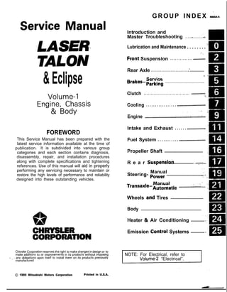
  • 1. &Eclipse GROUP INDEX &ma Service Manual LASER TALON Volume-l Engine, Chassis & Body FOREWORD This Service Manual has been prepared with the latest service information available at the time of ‘* publication. It is subdivided into various group categories and each section contains diagnosis, disassembly, repair, and installation procedures along with complete specifications and tightening references. Use of this manual will aid in properly performing any servicing necessary to maintain or restore the high levels of performance and reliability designed into these outstanding vehicles. 1, w A CHRYSLER CORPORATION Chrysler Corporation reserves the right to make changes in design 0’: to make additions to or improvements in its products without lmqoslng d ., . any obligations upon itself to install them on its products previously manufactured. 0 1990 Mitsubishi Motors Corporation Printed in U.S.A. Introduction and Master Troubleshooting ......,.........r... m , Lubrication and Maintenance . . . . . . . . ‘- 0 ‘8 ; “. i, .Front Suspension . . . . . . . . . . . . . . ..*............d... Rear Axle ..............................‘.................... . / Service Brakes-Parking ...................................... Clutch ................................. ..~...................... ‘t. Cooling . . . . . . . . . . . . . . . . . ..i.................................... ,., .‘, -, Engine ..i....~....r...............~....~.*,.~.~.~,‘~~...;..~~.. Intake and Exhaust . . . . . . ..L.................... Fuel System . . . . . . . . . . . ..ti.......r................~... Propeller Shaft ....................................... I R e a r Suspensiori ......................... ....y.f... Manual Steering- Power ..................................... Manual I transaxle-Automatic .............:;i...,; .... .; Wheels and Tires ................................. Body ............................................................. Heater & Air Conditioning .............. Emission Contr6l Systems .............. INOTE: For Electrical, refer to Volume-2 “Electrical”.
  • 2. 2 INTRODUCTION AND MASTER TROUBLESHOOTING - How to Use This Manual HOW TO USE THIS MANUAL NOaM CONTENTS The preceding page contains GROUP INDEX which lists the group title and group number. PAGE NUMBERS All page numbers consist of two sets of digits separated by a dash. The digits preceding the dash identify the number of the group. The digits follow- ing the dash represent the consecutive page num- ber within the group. The page numbers can be found on the top left or right of each page. TEXT Unless otherwise specified, each service procedure covers all models. Procedures covering specific models are identified by the model codes, or similar designation (engine type, transaxle type, etc.). A description of these designations is covered in this unit under “VEHICLE IDENTIFICATION”. TROUBLESHOOTING Troubleshootings are classified into master trouble- shooting and group troubleshooting and located as follows: The master troubleshooting is prepared when the trouble symptom relates to two or more groups and given in MASTER TROUBLESHOOTING. The group troubleshooting guide is prepared for causes of problems related to that individual group only; a troubleshooting guide is prepared for each appropriate group. LIMIT -9 Shows the standard for judging the quality of a part - or assembly on inspection and,means the maximum or minimum value within which the part or assembly must be kept functionally or in strength. It is a value established outside the range of standard value. Removal steps : The numbers before part name correspond to numbers in the illustration, and indicate the order of removal. Disassembly steps : The numbers before part name correspond to num- bers in the illustration, and indicate the order of disassembly. Installation steps : This is provided if installa- tion cannot’be made in the reverse order of “Removal steps “; omitted if installa- tion in the reverse order of “Removal steps” k possi- ble. Reassembly steps : This is .provided if reas- sembly cannot be made rL+ . . in the reverse order of “Disassembly steps” ; omitted if reassembly in the reverse order of “Dis- assembly steps” is possi- ble. SERVICE PROCEDURES The service steps are arranged in numerical order and attentions to be paid in performing vehicle service are described in detail in SERVICE POINTS. .IVL , -....- ce : Removal l 4 : Installation DEFINITION OF TERMS STANDARD VALUE Indicates the value used as the standard for judging the quality of a part or assembly on inspection or the value to which the part or assembly is corrected and adjusted. It is given by tolerance. MODEL INDICATIONS The following abbreviations are used in this manual for classification of model types. M/T : Indicates the manual transaxle, or models equipped with the manual transaxle. A/T: Indicates the automatic transaxle, or models equipped with the automatic transaxle. MPI: Indicates the multi-point injection, or engines equipped with the multi-point injection. SOHC: Indicates an engine with the single overhead camshaft, or a model equipped with such an engine. DOHC: Indicates an engine with the double overhead camshaft, or a model equipped with such an engine. Turbo: Indicates an engine with turbocharger, or a model equipped with such an engine. Non-Turbo: Indicates an engine without turbocharger, or a model equipped with such an engine. FWD: Indicates the front wheel drive vehicles. AWD: Indicates the all wheel drive vehicles. ABS: Indicates the anti-lock braking system or models equipped with the anti-lock braking system.
  • 3. INTRODUCTION AND MASTER TROUBLESHOOTING - How to Use This Manual 3 Page number Group title I Indicates the incidental operation to be performed before removal or after installa- 524 4 4 BRAKES-Roar Brake Wlmd Cylinder REAR BRAKE WHEEL CYLINDER - - - 3ENjOVAL AND lNSTAU.AllON I I Remwal stepa 1. Brake drum 2. Bleeder screw 3. Brake tube connection l * 4. Wheel cylinder assembly l e 5. Wheel cylinder boot l + 6. Piston assembly n** 7. Piston cue NOTE I1 l Reverse the removal procedures to reinstall. 12) M : Refer to ‘Service Points of Aemcval”. (3) l * : Refer to ‘Service Points of Installation’. 14) q :Nc+-r-reusab(epatts SERWE POINTS REMOVAL’ -7. REMOVAL OF PISTON CUP Using a screwdriver, remove the piston cup from the piston. INSPECTION - Check the following points. and if there is any abnormality, replace the entire wheel cylinder assembly. (1) Check piston and wheel cylinder walls for rust or damage. (2) Check clearance between the cylinder and the piston. Measure in two perpendicular directions to figure the clear- ance between the wheel cylinder inner diameter fmax.value) and the piston outer diameter (minvalue). Limit : 0.15 mm (4059 in.) NOTE If the difference is more than the limit, replace the piston and wheel cylinder as an assembly. This number corresponds to the number in “Removal steps”, “Disassembly steps”, “Installation steps” or “Reassembly steps”.
  • 4. 4 INTRODUCTION AND MASTER TROUBLESHOOTING - How to use This Manual EXPLANATION OF THE TROUBLESHOOTING GUIDE 3. Checking the passenger compartment-temperature sensor, outside-air sensor, air- thermostat sensor and refrigerant-temperature sensor circuits rIndicates the circuit diagram for checking (including the interface of the air conditioner control unit). I I* in the opera- tion descrip- tions only as necessary, and these numbers correspond to the numbers used in har- ness and com- ponent layout l 1 I-- Operation description A negative-characterlstlc thermstor 1s employed for each sensor in order 10 convey the amblent temperature of the sensor pan ,o resistance The sensor power-supply I2 5V) of the awcondltww ““I, IS applied to the lermlnals 116). (15). (17) (5) dlvlded res~~,ance reSlSta”ce R Provides the scription of cir- cuit operation for basic under- standing. I diaarams. Tmublrhooting 4 Dlagnosls No 12 The ou,s,de-a,, sensor ,nput slgnal IS held to 15°C 159°F) No 13 The air-thermostat tensor ~np”t slgnal IS held 10 4°C 139°F) Provides hints (including judgement) when trouble- cedures are fol- lowed. I Terminal I S’g”a’ CO”dl,,O”* Terminal voltage NO I 1 Indicates the diagnosis out- put code No. and the system conditions dur- kng o u t p u t . the conditions un- der which the be made. Indicates the specification to be used for judgement of the check results. If there is no particular men- tion of conditions in the “Conditions” column, the column shows the specifica- tion under normal condi- tions.
  • 5. https://www.aservicemanualpdf.com/ My Dear Friend! Thank you very much for visiting. Full manual if required, please enter the following URL into your browser. https://www.aservicemanualpdf.com/
  • 6. INTRODUCTION AND MASTER TROUBLESHOOTING - ‘How to use miS .Manual 5 EXPLANATION OF CIRCUIT DIAGRAMS -I The symbols used in circuit diagrams are used as described below. NOTE For detailed information cqncqning the reading of circuit diagrams, refer to GROUP 8-Wi@ng Har- ness. The input/output (dire%% of current flow) relative to the electronic control unit is indicated by symbols (A.m. The (A) symbol indicates that current flows in the upward direction. Output Indicates a connector. IGNITION SWITCH(IG1) Input .A Input/output reht flow is indicat- : ed by the arrow. In this instance, the current flow is in both directions, up The connector symbol indicates the device side connector (for an intermediate con- nector, the male side connector) as seen from the terminal front (the connector’s connection face). c device side con- device side con- L I Indicates the branch point of a harness of a differ- ent line diameter nr line colour. I Indicates that the con- nector is the direct-inser- tion type.
  • 7. 6 INTRODUCTION AND MASTER TROUBLESHOOTING - Vehicle Identificetion VEHICLE IDENTIFICATION Nmx- VEHICLE IDENTIFICATION NUMBER LOCATION The vehicle identification number (V.I.N.) is located oh a plate attached to the left top side of the instrument panel. VEHICLE IDENTIFICATION CODE CHART PLA.4 All vehicle identification numbers contain 17 digits. The vehicle number is a code which tells country, make, vehicle type, etc. 5th Digit r 8th Digit r 9th Digit 11th Digit 12th to 17th Digits 10th Digit Model year M- 1991 Year 7th Digit Body 4- 3 door Hatch- back Engine T- 1.8 liter (107 cu.in.) [SOHC- MPI1 R- 2.0 liters (122 cu.in.) [DOHC- MPI] u- 2.0 liters (122 cuin.) [DOHC- MPI- Turbo] 6th Digit Price class 3- Medium 4- High 5- Premium 6- Special 4th Digit Others B- Manual Seat Belt c- Auto- matic Seat Belt 3rd Digit Vehicle We 3- Passen- ger Car 2nd Digit Make E- Eagle P- Plymouth 1st Digit Country 4- USA Serial number *Check Plant Line E- DSM S- Laser or Talon FWD T- Talon AWD 000001 to 999999 I NOTE * “Check digit” means a single number or letter x used to verify the accuracy of transcription of vehicle identification number.
  • 8. INTRODUCTION AND MASTER TROUBLESHOOTING - Vehicle Identification VEHICLE IDENTIFICATION NUMBER LIST NOOCC-- p, VEHICLES FOR FEDERAL ,.. I V.I.N. (except sequence number) Brand Engine Displacement Models Code ,,; * /./ 4P3CS34aM E Plymouth Laser 1.8 liter (107 cuin.) D21AMNJElXP/RJEL4P’ 4P3CS44aME [SOHC-MPI] D21AMNHEL4P/RHEL4P 4P3CS44ROME 2.0 liter (122 cuin.) [DOHC-MPI] D22AMNHML4P/RHML4P 4P3CS44UuME 2.0 liter (122 cu.in.) [DOHC-MPI-Turbo] D22AMNHFL4P/RHFL4P 4E3CS44ROM E Eap$DTrlon 2.0 liter (122 cu.in.) [DOHC-MPI] D22AMNHML4EIRHML4E 4E3CS54UnME 4E3CT64UOME Eagle Talon <AWD> 2.0 liter (122 cu.in.) [DOHC-MPI-Turbo] D22AMNPFL4EIRPFL4E D27AMNGFL4E/kGFL4E .1 L *, VEHICLES FOR CALIFORNIA V.I.N. (except sequence number) Brand Engine Displacement M o d e l s C o d e 4P3CS34aME Plymouth Laser 1.8 liter (107 cu.in.) D21AMNJELSP/RJELSP 4P3CS44aME [SOHC-MPI] D21AMNHELSP/RHELSP 4P3CS44RmME 2.0 liter (122 cuin.) [DOHC-MPI] D22AMNHMLSP/RHMLSP 4P3CS44UOME 2.0 liter (122 cu.in.1 [DOHC-MPI-Turbo] D22AMNHFLSP/RHFLSP ‘. 4E3CS44RuME Eagle Talon 2.0 liter (122 cu.in.1 <FWD> [DOHC-MPI] D22AMNHMLSE/RHMLSE 4E3CS54UOME 4E3CT64UOME Eagle Talon <AWD> 2.0 liter (122 cu.in.1 [DOHC-MPI-Turbo] D22AMNPFLSElRPFLSE D27AMNGFLSE/RGFLSE VEHICLES FOR CANADA V.I.N. (except sequence number) Brand Engine Displacement Models Code 1’ 1 4P3BS34aME 4P3BS44aME Plymouth Laser 1.8 liter (107 cu.in.1 [SOHC-MPI] D21AMNJEL5P/RJEL5P D21AMNHiL5P/RHEL5P 4P3BS44ROME 2.0 liter (122 cuin.) [DOHC-MPI] D22AMNHML5P/RHML5P 4P3BS44UuME 2.0 liter (122 cu.in.) [DOHC-MPI-Turbo] D22AMNHFL5P/RHFL5P 4E3BS44ROME Eagle Talon 2.0 liter (122 cu.in.) D22AMNHML5EiRHML5E <FWD> [DOHC-MPI] I I 4E3BS54UuME 4E3BT64UnME Eagle Talon <AWD> 2.0 liter (122 cu.in.1 [DOHC-MPI-Turbo]
  • 9. 8 INTRODUCTION AND MASTER TROUBLESHOOTING - Vehicle Identification VEHICLE INFORMATION CODE PLATE NOOCD- Vehicle information code plate is riveted onto the bulkhead in ri the engine compartment. The plate shows model code, engine model, transaxle model, and body color code. 1. MODEL 2. ENGINE 3. TRANSAXLE 4. COLOR, TRIM OPT D22AMN HML4P 2 y$y:/e ‘f$$l 4G63 IEngine model F5M33 y Transaxle model B14 I Monotone exterior color code VEHICLE SAFETY CERTIFICATION LABEL NOOCF- 1. The vehicle safety certification label is attached to the face 2. This label indicates the month and year of manufacture, ;e Gross Vehicle Weight Rating (G.V.W.R.), Gross Axle (G.A.W.R.) front and rear, and Vehicle Identification Number (V.I.N.). ENGINE MODEL STAMPING NOOCG- 1. The engine model number is stamped at the front side on following: Engine model 4637 Engine displacement 1.8 liter (107 cu.in.) [SOHC-MPI] 4G63 2.0 liter (122 cuin.) [DOHC-MPI] or [DOHC-MPI-Turbo] 2. The engine serial number is stamped near the engine model number, and the serial number cycles, as shown below. Engine serial number Number cycling AA0201 t o w9999 AA0201 ------- -*AA99997 I 1 LAB0001 - - - - - - - +AY9999 : 1 I 1 t-BAOOOI - - - - - - - +YY9999 ’ 1 ‘-w
  • 10. INTRODUCTlON AND MASTER TROUBLESHOOTING - Vehicle Identification 9 Theft protection label onginal parts w ,I e IW B ,w w OOA0212 For replacement parts OOA0213 LOCATIONS THEFT PROTECTION NowlAB In order to protect against theft, a Vehicle Identification Number WIN) is stamped in, or attached as a label to, the following major parts of the engine and transaxle, as tiell as main outer panels: Engine cylinder block, Transaxle housing, Fender, Door, Quar- ter panel, Hood, Trunk lid, Bumpers In addition, a theft-protection label is attached to replacement parts for the body outer panel main components, and the same data are stamped into replacement parts for the engine and the transaxle. Cautions regarding panel repairs 1. When repainting original parts, do so after first mask- ing the theft-protection label, and, after painting, be sure to peel off the masking tape. 2. The theft-protection label for replacement parts is covered by masking tape, so such parts can be painted as is. The masking tape should be removed after painting is finished. 3. The theft-protection label should not be removed from original parts or replacement parts. OOA0057 OOA0055
  • 11. IO INTRODUCTION AND MASTER TROUBLESHOOTING - Vehicle Identification Part Transaxle Manual transaxle Automatic transaxle Fender The illustration indicates left hand side, outer. 3lA0259 Door 31AO250 - .
  • 12. INTRODUCTION AND MASTER TROUBLESHOOTING - Vehicle Identification 11 Part Quarter panel Target area : for original equipment parts : for replacement parts The label is attached at the inner side of the parts showr in the figure. Hood The illustration indicates left hand side, outer. Right hand side is symmetrically opposite. 31A026E The label is attached at the inner side of the parts shown in the figure. Tailgate 31A0256 The label is attached at the inner side of the parts shown in the figure. 31AO260
  • 13. 12 INTRODUCTION AND MASTER TROUBLESHOOTING - Vehicle Identification Part Front bumper Target area m : for original equipment parts m : for replacement parts Rear bumper The label is attached at the inner side of the parts shown in the figure. 31A0332 The label is attached at the inner side of the parts shown in the figure. 31A0332
  • 14. INTRODUCTION AND MASTER TROUBLESHOOTING - Precautions befdre Service ‘1 S OOV663 OOY192 FOOO 1. FOOO18 0OOD511 J7 PRECAUTIONS BEFORE SERVICE wxww PROTECTING THE VEHICLE If there is a likelihood of damaging painted or interior parts during service operations, protect them with suitable covers (such as seat covers, fender covers, etc.). REMOVAL AND DISASSEMBLY When checking a malfunction, find the cause of the problem. If it is determined that removal and/or disassembly is necessary, perform the work by following the procedures contained in this Service Manual. If punch marks or mating marks are made to avoid error in assembly and to facilitate the assembly work, be sure’to make them in locations which will have no detrimental effect on performance and/or appearances. If an area having many parts, similar parts, and/or parts which are symmetrical right and left is disassembled; be sure to arrange the parts so that they do not become mixed during the assembly process. 1. Arrange the parts removed in the proper order. 2. Determine which parts are to be reused and which are to be replaced. 3. If bolts, nuts, etc., are to be replaced, be sure to use only the exact size specified. i:c ” -,. > ‘. .“i,. i ” ,,‘. 5, SPECIAL TOOLS If other tools are substituted for the special tools to do service or repair work, there is the danger that vehicle parts might be damaged, or the technician might be injured; therefore, be sure to use the special tool whenever doing any work for which the use of one is specified. PARTS TO BE REPLACED If any of the following parts are removed, they must be replaced with new parts. 1. Oil seals 2. Gaskets (except rocker cover gasket) 3. Packings 4. O-rings 5. Lock washers 6. Cotter pins 7. Self-locking nuts
  • 15. I4 INTRODUCTION AND MASTER TROUBLESHOOTING - Precautions before Service mm (In.1 smo59 PARTS When replacing parts, use MOPAR genuine parts. VEHICLE WASHING If high-pressure car-washing equipment or steam car-washing equipment is used to wash the vehicle, be sure to maintain the spray nozzle at a distance of at least 300 mm (12 in.) from any plastic parts and all opening parts (doors, luggage compart- ment, etc.). SERVICING ELECTRICAL SYSTEM 1. Note the following before proceeding with work on the electrical system. Note that the following must never be done: Unauthorized modifications of any electrical device or wiring, because such modifications might lead to a vehicle malfunction, over-capacity or short-circuit that could result in a fire in the vehicle. 2. When servicing the electrical system, disconnect the negative cable terminal from the batten/. Caution 1. Before connecting or disconnecting the negative cable, be sure to turn off the ignition switch and the lighting switch. (If this is not done, there is the possibility of semiconductor parts being damaged.) 2. For MPI-equipped models, after completion of the work steps [when the battery’s negative (-) termi- nal is connected], warm up the engine and allow it to idle for approximately five minutes under the conditions described below, in order to stabilize engine control conditions, and then check to be sure that the idling is satisfactory. Engine coolant temperature: 85-95°C (185-203°F) Lights, electric fans, accessories: OFF Transaxle: neutral position (A/T models: “N” or “P”) Steering wheel: neutral (center) position
  • 16. INTRODUCTION AND MASTER TROUBLESHOOTING - Precautions before Set&e 15 F16171 Correct Cl6385 Cl6367 Y16347 WIRING HARNESSES 1. Secure the wiring harnesses by using cla’mps. However, for any harness which passes to the engine or other vibrating parts of the vehicle, allow some slack within a range that does not allow the engine vibrations to cause the harness to come into contact with any of the surrounding parts. Then secure the harness by using a clamp. In addition, if a mounting indication mark (yellow tape) is on a harness, secure the indication mark in the specified location. 2. If any section of a wiring harness contacts the edge of a part, or a corner, wrap the section of the harness with tape or something similar in order to protect it from damage. 3. When disconnecting a connector, be sure to pull only the connector, not the harness. 4. Disconnect connectors which have catches by pressing in the direction indicated by the arrows in the illustration.
  • 17. 16 INTRODUCTION AND MASTER TROUBLESHOOTING - Precautions before Service Cl6362 OOYSss OOV833 10A 15A COY569 5. Connect connectors which have catches by inserting the connectors until they snap. 9% ELECTRICAL COMPONENTS 1. When installing any of the vehicle parts, be careful not to pinch or damage any of the wiring harnesses. 2. Sensors, relays, etc., are sensitive to strong impacts. Handle them with care so that they are not dropped or mishandled. ,** 3. The electronic parts used for relays, etc., are sensitive to heat. If any service which causes a temperature of 80°C (176°F) or more is performed, remove the part or parts in question before carrying out the service. FUSES AND FUSIBLE LINKS 1. If a blown-out fuse is to be replaced, be sure to use only a fuse of the specified capacity. If a fuse of a capacity larger than that specified is used, parts may be damaged and the circuit may not be protected adequately. Caution 1. If a fuse is blown-out, be sure to eliminate the cause of the problem before installing a new fuse. ;i 2. Check the condition of fuse holders. If rust or dirt is found, clean metal parts with a fine-grained sand- paper until proper metal-to-metal contact is made. Poor contact of any fuse holder will often lead to voltage drop or heating in the circuit and colild result in improper circuit operation.
  • 18. INTRODUCTION AND MASTER TROUBLESHOOTING - Precautions before Sew&e ‘37 Nominal size SAE gi:e Permissible current In engine Other compart- areas ment 0.3 mm2 AWG 22 - 5A 0.5 mm2 AWG 20 7A 13A 0.85 mm’ AWG 18 9A 17A 1.25 mm2 AWG 16 12A 22A 2.0 mm2 AWG 14 16A 30A 3.0 mm’ AWG 12 21A 40A 5.0 mm2 AWG 10 31A 54A r ‘. oorsas 2. If additional optional equipment is to be installed, in ttie vehicle, follow the procedure listed in the ap@@priate instruction manual; however, be sure to pay “careful attention to the following points: “9: (1) In order to avoid overloading the wiring;’ take the electrical current load of the optional ,equipment into consideration, and determine the appropriate .wire size: (2) Where possible, route the wiring through the existing harnesses. (3) If an ammeter or similar instrument is to be connected to a live-wire circuit, use tape to protect the wire, use a clamp to secure the wire, and make sure that there is no contact with any other parts. (4) Be sure to provide a fuse for the load circuit of the optional equipment. TUBES AND OTHER RUBBER PARTS Be careful to avoid spilling any gasoline, oil, etc., or rubber parts, they might be adversely affected. LUBRICANTS In accordance with the instructions in this Service Manual, apply the specified lubricants in the specified locations during assembly and installation. !’ IV/ : >,I BRAKE FLUID Be careful to avoid spilling any brake fluid on painted surfaces, because the paint coat might be discolored or damaged.
  • 19. 18 INTRODUCTION AND MASTER TROUBLESHOOTING - Precautions b&ire Service DOING SERVICE WORK IN GROUPS OF VO’bR MORE TECHNICIANS .- I-7. I If the service work is to be done by two or more technicians working together, extra caution must be taken. Voltage distribution Maximum voltage NOTE ON INSTALLATION OF RADIO EQIJIPMEATe The computers of the electronic control system has been designed so that external radio waves will not interfere with their operation. However, if antenna or cable of amateur transceiver etc. is routed near the computers, it may affect the operation of the computers, even if the output of the transceiver is no more than 25W. To protect each of the computers from interference by transmitter (hum, transceiver, etc.), the following should be observed. 1. Install the antenna on the roof or rear bumper. 2. Because radio waves are emitted from the coaxial cable of the antenna, keep it 200 mm (8 in.) away from the computers and the wiring harness. If the cable must cross h the wiring harness, route it so that it runs at right angles to the wiring harness. 3. The antenna and the cable should be well matched, and the standing-wave ratio* should be kept low. 4. A transmitter having a large output should not be installed in the vehicle. 5. After installation of transmitter, run the engine at idle, emit radio waves from the transmitter and make sure that the engine is not affected. “STANDING-WAVE RATIO If an antenna and a cable having different impedances are connected, the input impedance Zi will vary in accordance with the length of the cable and the frequency of the transmitter, and the voltage distribution will also vary in accordance with the location. The ratio between this maximum voltage and minimum voltage is called the standing-wave ratio. It can also be represented by the ratio between the impedances of the antenna and the cable. The amount of radio waves emitted from the cable increases as the standing-wave ratio increases, and this increases the possibility of the electronic components being adversely affected.
  • 20. c -- INTRODUCTION AND MASTER TROUBLESHOOTtNG - Towing and Hoi&g T9 I- Sling type Wheel lift type Flat bed type iling type Vheel lift type lat bed type TOWING AND HOISTING NOOGA- llJ/RE;~R TOWING RECOMMENDATION FRONT TOWING PICKUP Caution This vehicle cannot be towed by a wrecker using sling-type equipment to prevent the bumper from deformation. If this vehicle is towed, use wheel lift or flat bed equipment. The vehicle may be towed on its rear wheels for extended distances provided the parking brake is released. It is recom- mended that vehicles be towed using the front pickup whenever possible. REAR TOWING PICKUP Caution This vehicle cannot be towed by a wrecker using sling-type equipment to prevent the axle beam from deformation. lf this vehicle is towed, use wheel lift or flat bed equipment. Manual transaxle vehicles may be towed on the front wheels, provided the transaxle is in neutral and the drive-line has not been damaged. The steering wheel must be clam,ped in the straight-ahead position with a steering wheel clamping device designed for towing service use. Caution Do not use steering column lock to secure front wheel position for towing. 3,“’ Automatic transaxle vehicle may be towed on the frontwheels at speeds not to exceed 50 km/h (30 mph) for a distances hot to exceed 30 km (18 miles). Caution If these limits cannot be met, the front wheels must ‘be placed on a tow dolly. TOWING WHEN KEYS ARE NOT AVAILABLE When a locked vehicle must be towed and keys are not available, the vehicle may be lifted and towed from the front,, provided the parking brake is released: If not released, the rear wheels should be placed on a tow dolly. I
  • 21. 20 INTRODUCTION AND MASTER TROUBLESHOOTING - Towing and Hoisting Frame contact support location OOAOI 71 <FWD>: 928mm (36.5 in.) <AWD>: 998mm (39.3 in.) I <FWD> Rear <AWD> I SAFETY PRECAUTIONS The following precautions should be taken when towin the vehicle. 1. DO NOT LIFT OR TOW THE VEHICLE BY ATTACHING TO OR WRAPPING AROUND THE BUMPER. 2. Any loose or protruding parts of damaged vehicle such as hoods, doors, fenders, trim, etc., should be secured prior to moving the vehicle. 3. Operator should refrain from going under a vehicle while it is lifted by the towing equipment, unless the vehicle in adequately supported by satefy stands. 4. Never allow passengers to ride in a towed vehicle. 5. State and local rules and regulations must be followed when towing a vehicle. <AWD> Refer to the section “Special Handling Instructions for AWD Models”. HOISTING POST TYPE Special care should be taken when raising the vehicle on a frame contact type hoist. The hoist must be equipped with the proper adapters in order to support the vehicle at the proper locations. Caution When service procedures require removing rear sutpen- sion, fuel tank, spare tire and lift gate, place addmonal weight on rear end of vehicle or anchor vehicle to hoist to prevent tipping of center of gravity changes. FLOOR JACK The usual type of floor jack is used at the following locations. Front: <FWD> Under the mid point of centermember <AWD> Under the mid point of crossmember Rear: <FWD> Under the jack up bracket of rear floor pan <AWD> Under the rear differential Cautions 1. Never use a jack at the lateral rod or rear suspension assembly. <FWD> 2. In order to prevent scarring the centermember <MID> or crossmember <AWD>, place a piece of cloth on the jack’s contact surface (to prevent corrosion caused by damage to the coating). 3. A floor jack must never be used on any part of the underbody. 4. Do not attempt to raise one entire side of the vehicle by placing a jack midway between front and rear wheels. This practice may result in permanent damage to the body.
  • 22. -- INTRODUCTION AND MASTER TROUBLESHOOTING - Towing and Hoisting 2”1 LIFTING, JACKING SUPPORT LOCATION -4WD> <AWD> lOA Floor jack locations OOAOO2 1 * Approximate center of gravity @ Frame contact hoist, twin post hoist or scissors jack (emergency) locations EMERGENCY JACKING Jack receptacles are located at the body sills to accept the scissors jack supplied with the vehicle for emergency road service. Always block opposite wheels and jack on level surface.
  • 23. 22 INTRODUCTION AND MASTER TROUBLESHOOTING - %%c%:k! ‘nstructions SPECIAL HANDLING INSTRUCTIONS FOR AWD MODELS NWUAAB TOWING Towing methods If a tow truck is used Lifting method for 4 wheels-Good Remarks l For AWD models, the basic principle is that all four wheels are to be raised before towing. l The shift lever should be set to 1 st gear and thhrting brake should be applied. l The selector lever should be set to “P” position and the parking brake should be applied. <AA> OOAO032 Front wheels lifted-No good l The vehicle must not be towed by placing only its front wheels or only the rear wheels on a rolling dolly, because to do so will result in deterioration of the viscous coupling and result in the viscous coupling causing the vehicle to jump forward suddenly. OOA0034 Front wheels IifteddNo good l If only the front wheels or only the rear wheels are lifted for towing, the bumper will be damaged. In addition, lifting of the rear wheels causes the oil to flow forward, and may result in heat damage to the rear bushing of the transfer, and so should never be done. llA0060 Rear wheels lifted-No good OOA0033
  • 24. Special Handling lnstruction~ INTRODUCTION AND MASTER TROUBLESHOOTING - for AWD Models 2 3 7T T Free roller 00P0030 T&a T Axle stand OOPOO37 Front tie-down bracket 16PO209 14A0198 OOPO036 SPEEDOMETER TEST IF A FREE ROLLER IS USED 1. Set the free roller on the floor (at the rear wheels) so that it is aligned with the vehicle’s wheelbase and the rear tread. 2. Carefully move the vehicle onto the tester and free roller. 3. Set the speedometer tester in place. 4. Perform the speedometer test. For information concerning the measurement of speed and the allowable error, refer to GROUP 8-Meters and Gauges. Caution Do not operate the clutch suddenly, or increase or reduce speed suddenly during the work. IF THE REAR WHEELS ARE JACKED UP 1. Move the vehicle onto the speedometer tester. 2. Jack up the rear wheels, and place axle stands at the designated part of the side sill. 3. Perform the speedometer test. For information concerning the measurement of speed and the allowable error, refer to GROUP 8-Meters and Gauges. Caution Do not operate the clutch suddenly, or increase or reduce speed suddenly during the work. Front wheel side slip To prevent the front wheels from moving from side to side, attach tension bars to the front tie-down brackets, and secure both ends at anchor plates. Accident prevention procedures (1) Attach a chain or wire to the rear tie-down hole. (Refer to GROUP 8-Meters and Gauges.) Make sure the end of the wire or chain is secured firmly. (2) Take all other necessary precautions. BRAKE TEST In order to stabilize the viscous coupling’s dragging force, the brake test should always be conducted after the speedometer test. FRONT WHEEL MEASUREMENTS 1. Place the front wheels on the brake tester. 2. Perform the brake test. Caution The rear wheels should remain on the ground. 3. If the brake dragging force exceeds the specified value, jack up the vehicle and manually rotate each wheel to check the rotation condition of each wheel. NOTE If the brake dragging force exceeds the specified value, the cause may be the effect of the viscous coupling’s dragging force, so jack up the front wheels and check the rotation condition of the wheels in this state for no effect by the viscous coupling’s dragging force.
  • 25. 24 INTRODUCTION AND MASTER TROUBLESHOOTING - fSo%k%:~~it’ndrU~ions REAR WHEEL MEASUREMENTS After placing the rear wheels on the brake tester, follow the same procedures as for the front wheel measurements. ,’ ~. Braking force of AWD models with VCU Balancing machine Pick-up stand WA0024 Braking force Each wheel Left/right sum Left/right difference At 90kg (198 60% or more of Ibs.) pedal de- front axle weight pression force Rear wheels: 330 kg (727 Ibs.) or more 8% or less of axle weight Total At 90kg (198 830 kg (1,829 Ibs.) Ibs.) pedal de- or more* pression force * About 20 kg (44 Ibs.) of force by viscosity torque has been added. or... I Braking-stop distance At primary velocity of 50 km/h (31 mph): Within 16.0m (52.5 ft.) WHEEL BALANCE .r=l FRONT WHEEL MEASUREMENTS 1. Jack up the rear wheels, and place an axle stand at the designated part of the side sill. 2. Jack up the front wheels and set a pick-up stand and balancing machine in place. Caution 1. Set so that the front and rear of the vehicle are at the same height. 2. Release the parking brake. 3. Rotate each wheel manually and check to be sure that there is no dragging. 3. Use the engine to drive the tires, and then make the measurement. Caution 1. If an error is indicated in the state of engine drive, motor drive can be used concurrently. 2. Do not operate the clutch suddenly, or increase or reduce speed suddenly during the work. REAR WHEEL MEASUREMENTS 1. Jack up the front wheels, and place an axle stand at the designated part of the side sill. 2. Jack up the rear wheels, and then, after setting a pick-up stand and balancing machine in place, follow the same procedure as for front wheel measurements. .&,
  • 26. INTRODUCTION AND MASTER TROUBLESHOOTING - :;k%ii::& and 25 GENERAL DATA AND SPECIFICATIONS NOOHA- OOAOl59 GENERAL SPECIFICATIONS <PLYMOUTH> z- A- l .8L Engine 1.8L Engine 2.0L DOHC 2.0L DOHC Items “Medium” “High” ~%n?urbo) :Tz%$ Vehicle dimensions mm(in.) Overall length 1 4,330 (170.5) 4,330 (170.5) 4,330 (I 70.5) 4,330 (170.5) Overall width 2 1,690 (66.5) 1,690 (66.5) 1,690 (66.5) 1,690 (66.5) Overall height 3 1,306 (51.4) 1,306 (51.4) 1,306 (51.4) 1,306 (51.4) Wheel base 4 2,470 (97.2) 2,470 (97.2) 2,470 (97.2) 2,470 (97.2) Tread Front 5 1,465 (57.7) 1,465 (57.7) 1,465 (57.7) 1,465 (57.7) Rear 6 1,450 (57.1) 1,450 (57.1) 1,450 (57.1) 1,450 (57:l i Overhang Front 7 950 (37.4) 950 (37.4) 950 (37.4) 950 (37.4) Rear 8 910 (35.8) 910 (35.8) 910 (35.8) 910 (35.8) Minimum running ground 9 160 (6.3) 160 (6.3) 160 (6.3) 160 (6.3) clearance mm (in.) Angle of approach degrees 10 15.3” 15.3” 15.3” 15.3” Angle of departure degrees 11 18.1” 18.1” ’ 18.1“ 18.1” Vehicle weight kg (Ibs.) Curb weights M/T 1,145 (2,524) 1,165 (2,568) 1,215 (2,679) 1,245 (2,745) AIT 1 ,I 70 (2,579) 1,190 (2,623) 1,240 (2,734) 1,280 (2,822) Gross vehicle weight rating 1,585 (3,494) 1,585 (3,494) 1,630 (3,594) ‘I ,670 (3,682) Gross axle weight rating Front 900 (1,984) 900 (1,984) 930 (2,050) 965 (2,127) Rear 685 (1,510) 685 (1,510) 700 (1,543) 705 ‘(1,554) Seating capacity 4 4 4 4 Engine Model No. 4G37 4637 4G63 4G63 Transaxle Model No. Manual transaxle F5M22 F5M22 F5M22 F5M33 Automatic transaxle F4A22 F4A22 F4A22 F4A33 Clutch Type Dry-single disc Dry-single disc Dry-single disc Dry-single disc & diaphragm & diaphragm & diaphragm & diaphragm spring spring spring spring
  • 27. 26 INTRODUCTION AND MASTER TROUBLESHOOTING - :;:%:a=and Items Chassis Tire Front suspension Type Rear suspension We Brake Type Steering Gear type Front Rear Gear ratio Fuel tank Capacity liters (gals.) <EAGLE> 1.8L Engine “Medium” Pl85/70R14 PI 85/70Rl4 Independent strut Independent strut 3lFk Torsion &k-k Torsion Disc Disc Disc Disc Rack and pinion 03 Rack and pinion cn 60 (16) 60 (16) Items Vehicle dimensions mm(in.) Overall length 1 Overall width 2 Overall height 3 Wheel base 4 Tread Front 5 Rear 6 Overhang Front 7 Rear 8 Minimum running ground 9 clearance mm (in.) Angle of approach degrees 10 Angle of departure degrees 11 Vehicle weight kg (Ibs.) Curb weights MiT Al-r Gross vehicle weight rating Gross axle weight rating Front Rear Seating capacity Engine Model No. 1.8L Engine “Medium” 2.0L DOHC Kr%n?u rbo) P205/55Rl6 89H ;;5/55R16 89V %55R16 88V Independent strut zx;;k Torsion Disc Disc Rack and pinion co 60 (16) 2.0L DOHC #b”; P205/55Rl6 89 or 205155R16 88V Independent strut 3Lnk Torsion Disc Disc Rack and pinion co 60 (16) 2.0L DOHC Engine (Non-Turbo) 4,330 (I 70.5) 1,690 (66.5) 1,306 (51.4) 2,470 (97.2) 1,465 (57.7) 1,450 (57.1) 950 (37.4) 910 (35.8) 160 (6.3) 15.3 18.1” 1,230 (2,712) 1,255 (2,767) 1,630 (3,594) 930 (2,050) 700 (1,543) 4 4G63 2.0L DOHC Engine (FWD-Turbo) 4,350 (171.3) 1,700 (66.9) 1,306 (51.4) 2,470 (97.2) 1,465 (57.7) 1,450 (57.1) 960 (37.8) 920 (36.2) 160 (6.3) 13.2” 18.1” 1,260 (2,778) 1,295 (2,855) 1,670 (3,682) 965 (2,127) 705 (1,554) 1 4G63 2.0L DOHC Engine (AWD-Turbo) 4,380 (I 72.4) 1,700 (66.9) 1,321 (52.0) 2,470 (97.2) 1,465 (57.7) 1,455 (57.3) 960 (37.8) 950 (37.4) 158 (6.2) 14.0” 17.6” 1,405 (3,097) 1,440 (3,175) I,81 0 (3,990) 1,005 (2,216) 805 (1,775) 4 4G63
  • 28. INTRODUCTION AND MASTER TROUBLESHOOTING - f~EEaZ% acld 27 =r 9.. Items Transaxle Model No. Manual transaxle Automatic transaxle Clutch Type Chassis Tire Front suspension Type Rear suspension Type Brake Type Steering Gear type Gear ratio Fuel tank Capacity 2.0L DOHC Engine 2.0L DOHC Engine 2.0L DOHC Engine (Non-Turbo) (FWD-Turbo) (AWD-Turbo) F5M22 F5M33 W5M33 F4A22 F4A33 W4A33 Dry-single disc Dry-single disc Dry-single disc & diaphragm spring & diaphragm spring & diaphragm spring P205/55R16 89H P205155R16 89V P205/55R16 89V o r 205/55R16 89V or 205/55R16 88V or 205/55R16 88V or 205/55R16 88V Independent strut Independent strut Independent strut 3-Link Torsion axle 3-Link Torsion axle Double wishbone Front Disc Disc D i s c Rear Disc Disc Disc Rack and pinion Rack and pinion Rack ,and pinion 03 co cc liters (gals.) 60 (16) 60 (16) 60 (16) ) ENGINE SPECIFICATIONS Items 4G37 4G63 Non-Turbo 4G63 Turbo Type In-line SOHC In-line DOHC In-line DOHC Number of cylinders 4 4 4 Bore mm (in.) 80.6 (3.17) 85.0 (3.35) 85.0 (3.35) Stroke mm (in.) 86.0 (3.39) 88.0 (3.46) 88.0 (3.46) Piston displacement cm3 (cu.in.) 1,755 (107) 1,997 (122) 1,997 (122) Compression ratio 9.0 9.0 7.8 Firina order 1-3-4-2 1-3-4-2 1-3-4-2 TRANSAXLE SPECIFICATIONS Items F5M22 F5M33 W5M33 F4A22 F4A33 W4A33 Type Gear ratio 1 st 2nd 3rd 4th 5th Reverse Transaxle Primary reduction ratio Secondary reduction ratio Transfer 5-speed M/T 5-speed M/T 3.363 3.090 1.947 1.833 1.285 1.217 0.939 0.888 0.756 0.741 3.083 3.166 5speed M/T 4-speed A/T 4-speed AIT 3.083 2.846 2.551 1.684 1.581 1.488 1.115 1.000 1 .ooo 0.833 0.685 0.685 0.666 - - 3.166 2.176 2.176 Qspeed AIT 2.551 1.488 1 .ooo 0.685 - 2.176 1.096 3.941 1.208 1.275 1.125 1.228 1.228 3.437 3.866 3.562 3.222 3.600 - 1.090 - - 1.090
  • 29. 28 INTRODUCTION AND MASTER TROUBLESHOOTING - Tightening Torque TIGHTENING TORQUE NOOJA- Each torque value in the table is a standard value for tightening under the following conditions. (1) Bolts, nuts and washers are all mode of steel and plated with zinc. (2) The threads and bearing surface of bolts and nuts are all in dry condition. The values in the table are not applicable: (1) If toothed washers are inserted. (2) If plastic parts are fastened. (3) If bolts are tightened to plastic or die-cast inserted nuts. (4) If self-tapping screws or self-locking nuts are used. Standard bolt and nut tightening torque I I I L Flange bolt and nut tightening torque Bolt nominal Pitch Torque Nm (ftlbs.) KTter (mm) Head mark 04 Head mark 0 7 Head mark 0 8 M6 1 .o 4 - 6 (2.9-4.3) 8-l 2 (5.8-8.7) 9-14 (6.5-10) M8 1.25 IO-15 (7.2-11) 19-28 (14-20) 22-33 (16-24) Ml0 1.25 21-31 (15-22) 39-60 (28-43) 50-65 (36-47) Ml0 1.5 19-29 (14-21) 36-54 (26-39) 45-65 (33-47) Ml2 1.25 38-55 (27-40) 80- 110 (58-80) 90- 120 (65-87) Ml2 1.75 34-52 (25-38) 70-95 (51-69) 85-l 10 (61-80) Taper thread tightening torque Torque Nm (ftlbs.) Thread size Female thread material: Light alloy Female thread material: Steel NPTF l/6 5-8 (3.6-5.8) 8-12 (5.8-8.7) PT l/8 8- 12 (5.8-8.7) 16’-20 (12-14) PT l/4, NPTF I/4 20-30 (14-22) 35-45 (25-33) PT 318 40-55 (29-40) 60-75 (43-54) NOTE: NPTF is dry seat pipe thread, while PT is pipe thread.
  • 30. INTRODUCTION AND MASTER TROUBLESHOOTING - Mast& Tro6blerhootbia MASTER TROUBLESHOOTING 7 * I, ._ ,... r. ENGINE OVERHEATS i ” Symptom Engine overheats Probable cause Cooling system faulty Incorrect ignition timing Reference page : I ._), 7 - 5 8-169 ENGINE WILL NOT CRANK OR CRANKS SLOWLY Symptom Engine will not crank or cranks slowly Probable cause Starting system faulty ,’ Reference page 8-153 ENGINE WILL NOT START OR HbRD TO START (CRANKS OK) Symptom Probable cause Reference page Engine will not start or hard to No fuel supply to injector - start (Cranks OK) Injection system problems - Ignition system problems 8-16!$ / ” ; Vacuum leaks 11-5 ..“, :’ l Purge control valve hose 25-4 l Vacuum hoses l Intake manifold l Air intake plenum l Throttle body l EGR valve Compression too low g-23, ‘, :. ” ‘,;A; ROUGH IDLE OR ENGINE STALL Symptom Rough idle or engine stalls Probable cause Vacuum leaks l Purge control valve hose l Vacuum hoses l Intake manifold l Air intake plenum l Throttle body l EGR valve “. ._ Reference page or remedy 11-5 25-4 Ignition system problems Idle speed set too low 8-169 Check idle speed control sys- tem Idle mixture too lean or too rich Fuel injection system problems Exhaust gas recirculation (EGR) system problems Engine overheats Compression too low - - 25-l 5 7 - 5 9-23
  • 31. Thank you very much for your reading. Please Click Here Then Get More Information.
  • 32. https://www.aservicemanualpdf.com/ My Dear Friend! Thank you very much for visiting. Full manual if required, please enter the following URL into your browser. https://www.aservicemanualpdf.com/