SlideShare a Scribd company logo
1 of 14
Download to read offline
&Eclipse
GROUP INDEX &ma
Service Manual
LASER
TALON
Volume-l
Engine, Chassis
& Body
FOREWORD
This Service Manual has been prepared with the
latest service information available at the time of
‘* publication. It is subdivided into various group
categories and each section contains diagnosis,
disassembly, repair, and installation procedures
along with complete specifications and tightening
references. Use of this manual will aid in properly
performing any servicing necessary to maintain or
restore the high levels of performance and reliability
designed into these outstanding vehicles.
1,
w
A
CHRYSLER
CORPORATION
Chrysler Corporation reserves the right to make changes in design 0’: to
make additions to or improvements in its products without lmqoslng
d ., . any obligations upon itself to install them on its products previously
manufactured.
0 1990 Mitsubishi Motors Corporation Printed in U.S.A.
Introduction and
Master Troubleshooting ......,.........r... m
,
Lubrication and Maintenance . . . . . . . . ‘-
0
‘8
; “. i,
.Front Suspension . . . . . . . . . . . . . . ..*............d...
Rear Axle ..............................‘....................
. /
Service
Brakes-Parking
......................................
Clutch ................................. ..~......................
‘t.
Cooling . . . . . . . . . . . . . . . . . ..i....................................
,., .‘, -,
Engine ..i....~....r...............~....~.*,.~.~.~,‘~~...;..~~..
Intake and Exhaust . . . . . . ..L....................
Fuel System . . . . . . . . . . . ..ti.......r................~...
Propeller Shaft ....................................... I
R e a r Suspensiori
......................... ....y.f...
Manual
Steering- Power .....................................
Manual I
transaxle-Automatic .............:;i...,; .... .;
Wheels and Tires .................................
Body .............................................................
Heater & Air Conditioning ..............
Emission Contr6l Systems ..............
INOTE: For Electrical, refer to
Volume-2 “Electrical”.
2 INTRODUCTION AND MASTER TROUBLESHOOTING - How to Use This Manual
HOW TO USE THIS MANUAL NOaM
CONTENTS
The preceding page contains GROUP INDEX which
lists the group title and group number.
PAGE NUMBERS
All page numbers consist of two sets of digits
separated by a dash. The digits preceding the dash
identify the number of the group. The digits follow-
ing the dash represent the consecutive page num-
ber within the group. The page numbers can be
found on the top left or right of each page.
TEXT
Unless otherwise specified, each service procedure
covers all models. Procedures covering specific
models are identified by the model codes, or similar
designation (engine type, transaxle type, etc.). A
description of these designations is covered in this
unit under “VEHICLE IDENTIFICATION”.
TROUBLESHOOTING
Troubleshootings are classified into master trouble-
shooting and group troubleshooting and located as
follows:
The master troubleshooting is prepared when the
trouble symptom relates to two or more groups and
given in MASTER TROUBLESHOOTING.
The group troubleshooting guide is prepared for
causes of problems related to that individual group
only; a troubleshooting guide is prepared for each
appropriate group.
LIMIT -9
Shows the standard for judging the quality of a part -
or assembly on inspection and,means the maximum
or minimum value within which the part or assembly
must be kept functionally or in strength. It is a value
established outside the range of standard value.
Removal steps : The numbers before part
name correspond to numbers
in the illustration, and indicate
the order of removal.
Disassembly steps : The numbers before part
name correspond to num-
bers in the illustration,
and indicate the order of
disassembly.
Installation steps : This is provided if installa-
tion cannot’be made in the
reverse order of “Removal
steps “; omitted if installa-
tion in the reverse order of
“Removal steps” k possi-
ble.
Reassembly steps : This is .provided if reas-
sembly cannot be made
rL+
. .
in the reverse order of
“Disassembly steps” ;
omitted if reassembly in
the reverse order of “Dis-
assembly steps” is possi-
ble.
SERVICE PROCEDURES
The service steps are arranged in numerical order
and attentions to be paid in performing vehicle
service are described in detail in SERVICE POINTS.
.IVL , -....-
ce : Removal
l 4 : Installation
DEFINITION OF TERMS
STANDARD VALUE
Indicates the value used as the standard for judging
the quality of a part or assembly on inspection or the
value to which the part or assembly is corrected and
adjusted. It is given by tolerance.
MODEL INDICATIONS
The following abbreviations are used in this manual for classification of model types.
M/T : Indicates the manual transaxle, or models equipped with the manual transaxle.
A/T: Indicates the automatic transaxle, or models equipped with the automatic transaxle.
MPI: Indicates the multi-point injection, or engines equipped with the multi-point injection.
SOHC: Indicates an engine with the single overhead camshaft, or a model equipped with such an
engine.
DOHC: Indicates an engine with the double overhead camshaft, or a model equipped with such an
engine.
Turbo: Indicates an engine with turbocharger, or a model equipped with such an engine.
Non-Turbo: Indicates an engine without turbocharger, or a model equipped with such an engine.
FWD: Indicates the front wheel drive vehicles.
AWD: Indicates the all wheel drive vehicles.
ABS: Indicates the anti-lock braking system or models equipped with the anti-lock braking system.
INTRODUCTION AND MASTER TROUBLESHOOTING - How to Use This Manual 3
Page number Group title
I
Indicates the incidental operation to be
performed before removal or after installa-
524 4 4
BRAKES-Roar Brake Wlmd Cylinder
REAR BRAKE WHEEL CYLINDER
-
-
-
3ENjOVAL AND lNSTAU.AllON
I I
Remwal stepa
1. Brake drum
2. Bleeder screw
3. Brake tube connection
l * 4. Wheel cylinder assembly
l e 5. Wheel cylinder boot
l + 6. Piston assembly
n** 7. Piston cue
NOTE
I1 l Reverse the removal procedures to reinstall.
12) M : Refer to ‘Service Points of Aemcval”.
(3) l * : Refer to ‘Service Points of Installation’.
14) q :Nc+-r-reusab(epatts
SERWE POINTS REMOVAL’
-7. REMOVAL OF PISTON CUP
Using a screwdriver, remove the piston cup from the piston.
INSPECTION -
Check the following points. and if there is any abnormality, replace
the entire wheel cylinder assembly.
(1) Check piston and wheel cylinder walls for rust or damage.
(2) Check clearance between the cylinder and the piston.
Measure in two perpendicular directions to figure the clear-
ance between the wheel cylinder inner diameter fmax.value)
and the piston outer diameter (minvalue).
Limit : 0.15 mm (4059 in.)
NOTE
If the difference is more than the limit, replace the piston and
wheel cylinder as an assembly.
This number corresponds to
the number in “Removal
steps”, “Disassembly
steps”, “Installation steps”
or “Reassembly steps”.
4 INTRODUCTION AND MASTER TROUBLESHOOTING - How to use This Manual
EXPLANATION OF THE TROUBLESHOOTING GUIDE
3. Checking the passenger compartment-temperature sensor, outside-air sensor, air-
thermostat sensor and refrigerant-temperature sensor circuits rIndicates the
circuit diagram
for checking
(including the
interface of the
air conditioner
control unit).
I I*
in the opera-
tion descrip-
tions only as
necessary, and
these numbers
correspond to
the numbers
used in har-
ness and com-
ponent layout
l 1
I--
Operation description
A negative-characterlstlc thermstor 1s employed for each sensor in order 10 convey the amblent
temperature of the sensor pan ,o resistance
The sensor power-supply I2 5V) of the awcondltww ““I, IS applied to the
lermlnals 116). (15). (17) (5) dlvlded res~~,ance
reSlSta”ce R
Provides the
scription of cir-
cuit operation
for basic under-
standing.
I diaarams.
Tmublrhooting 4
Dlagnosls
No 12 The ou,s,de-a,, sensor ,nput slgnal IS held to 15°C 159°F)
No 13 The air-thermostat tensor ~np”t slgnal IS held 10 4°C 139°F)
Provides hints
(including
judgement)
when trouble-
cedures are fol-
lowed.
I
Terminal
I S’g”a’
CO”dl,,O”* Terminal voltage
NO I
1
Indicates the
diagnosis out-
put code No.
and the system
conditions dur-
kng o u t p u t .
the
conditions un-
der which the
be made.
Indicates the specification to
be used for judgement of
the check results.
If there is no particular men-
tion of conditions in the
“Conditions” column, the
column shows the specifica-
tion under normal condi-
tions.
INTRODUCTION AND MASTER TROUBLESHOOTING - ‘How to use miS .Manual 5
EXPLANATION OF CIRCUIT DIAGRAMS
-I The symbols used in circuit diagrams are used as
described below.
NOTE
For detailed information cqncqning the reading of
circuit diagrams, refer to GROUP 8-Wi@ng Har-
ness.
The input/output (dire%%
of current flow) relative to
the electronic control unit
is indicated by symbols
(A.m.
The (A) symbol indicates
that current flows in the
upward direction.
Output
Indicates a
connector.
IGNITION
SWITCH(IG1)
Input .A Input/output
reht flow is indicat- :
ed by the arrow.
In this instance, the
current flow is in
both directions, up
The connector
symbol indicates
the device side
connector (for an
intermediate con-
nector, the male
side connector)
as seen from the
terminal front
(the connector’s
connection face).
c
device side con-
device side con-
L
I
Indicates the
branch point of a
harness of a differ-
ent line diameter
nr line colour. I
Indicates
that the con-
nector is the
direct-inser-
tion type.
6 INTRODUCTION AND MASTER TROUBLESHOOTING - Vehicle Identificetion
VEHICLE IDENTIFICATION Nmx-
VEHICLE IDENTIFICATION NUMBER LOCATION
The vehicle identification number (V.I.N.) is located oh a plate
attached to the left top side of the instrument panel.
VEHICLE IDENTIFICATION CODE CHART PLA.4
All vehicle identification numbers contain 17 digits. The vehicle
number is a code which tells country, make, vehicle type, etc.

5th
Digit
r
8th
Digit r
9th
Digit
11th
Digit
12th to
17th
Digits
10th
Digit
Model
year
M-
1991
Year
7th
Digit
Body
4-
3 door
Hatch-
back
Engine
T-
1.8 liter
(107
cu.in.)
[SOHC-
MPI1
R-
2.0 liters
(122
cu.in.)
[DOHC-
MPI]
u-
2.0 liters
(122
cuin.)
[DOHC-
MPI-
Turbo]
6th
Digit
Price
class
3-
Medium
4-
High
5-
Premium
6-
Special
4th
Digit
Others
B-
Manual
Seat Belt
c-
Auto-
matic
Seat Belt
3rd
Digit
Vehicle
We
3-
Passen-
ger Car
2nd
Digit
Make
E-
Eagle
P-
Plymouth
1st
Digit
Country
4-
USA
Serial
number
*Check
Plant
Line
E-
DSM
S-
Laser or
Talon
FWD
T-
Talon
AWD
000001
to
999999
I
NOTE * “Check digit” means a single number or letter x used to verify the accuracy of transcription of vehicle identification number.
INTRODUCTION AND MASTER TROUBLESHOOTING - Vehicle Identification
VEHICLE IDENTIFICATION NUMBER LIST NOOCC--
p, VEHICLES FOR FEDERAL
,.. I
V.I.N. (except sequence number) Brand Engine Displacement Models Code
,,; * /./
4P3CS34aM E Plymouth Laser 1.8 liter (107 cuin.) D21AMNJElXP/RJEL4P’
4P3CS44aME
[SOHC-MPI]
D21AMNHEL4P/RHEL4P
4P3CS44ROME 2.0 liter (122 cuin.)
[DOHC-MPI]
D22AMNHML4P/RHML4P
4P3CS44UuME 2.0 liter (122 cu.in.)
[DOHC-MPI-Turbo]
D22AMNHFL4P/RHFL4P
4E3CS44ROM E Eap$DTrlon 2.0 liter (122 cu.in.)
[DOHC-MPI]
D22AMNHML4EIRHML4E
4E3CS54UnME
4E3CT64UOME Eagle Talon
<AWD>
2.0 liter (122 cu.in.)
[DOHC-MPI-Turbo]
D22AMNPFL4EIRPFL4E
D27AMNGFL4E/kGFL4E
.1 L *,
VEHICLES FOR CALIFORNIA
V.I.N. (except sequence number) Brand Engine Displacement M o d e l s C o d e
4P3CS34aME Plymouth Laser 1.8 liter (107 cu.in.) D21AMNJELSP/RJELSP
4P3CS44aME
[SOHC-MPI]
D21AMNHELSP/RHELSP
4P3CS44RmME 2.0 liter (122 cuin.)
[DOHC-MPI]
D22AMNHMLSP/RHMLSP
4P3CS44UOME 2.0 liter (122 cu.in.1
[DOHC-MPI-Turbo]
D22AMNHFLSP/RHFLSP
‘.
4E3CS44RuME Eagle Talon 2.0 liter (122 cu.in.1
<FWD> [DOHC-MPI]
D22AMNHMLSE/RHMLSE
4E3CS54UOME
4E3CT64UOME Eagle Talon
<AWD>
2.0 liter (122 cu.in.1
[DOHC-MPI-Turbo]
D22AMNPFLSElRPFLSE
D27AMNGFLSE/RGFLSE
VEHICLES FOR CANADA
V.I.N. (except sequence number) Brand Engine Displacement Models Code 1’ 1
4P3BS34aME
4P3BS44aME
Plymouth Laser 1.8 liter (107 cu.in.1
[SOHC-MPI]
D21AMNJEL5P/RJEL5P
D21AMNHiL5P/RHEL5P
4P3BS44ROME 2.0 liter (122 cuin.)
[DOHC-MPI]
D22AMNHML5P/RHML5P
4P3BS44UuME 2.0 liter (122 cu.in.)
[DOHC-MPI-Turbo]
D22AMNHFL5P/RHFL5P
4E3BS44ROME Eagle Talon 2.0 liter (122 cu.in.) D22AMNHML5EiRHML5E
<FWD> [DOHC-MPI] I I
4E3BS54UuME
4E3BT64UnME Eagle Talon
<AWD>
2.0 liter (122 cu.in.1
[DOHC-MPI-Turbo]
8 INTRODUCTION AND MASTER TROUBLESHOOTING - Vehicle Identification
VEHICLE INFORMATION CODE PLATE NOOCD-
Vehicle information code plate is riveted onto the bulkhead in ri
the engine compartment.
The plate shows model code, engine model, transaxle model,
and body color code.
1. MODEL
2. ENGINE
3. TRANSAXLE
4. COLOR,
TRIM OPT
D22AMN HML4P
2 y$y:/e ‘f$$l
4G63
IEngine model
F5M33
y
Transaxle model
B14
I Monotone exterior
color code
VEHICLE SAFETY CERTIFICATION LABEL NOOCF-
1. The vehicle safety certification label is attached to the face
2. This label indicates the month and year of manufacture, ;e
Gross Vehicle Weight Rating (G.V.W.R.), Gross Axle
(G.A.W.R.) front and rear, and Vehicle
Identification Number (V.I.N.).
ENGINE MODEL STAMPING NOOCG-
1. The engine model number is stamped at the front side on
following:
Engine model
4637
Engine displacement
1.8 liter (107 cu.in.)
[SOHC-MPI]
4G63 2.0 liter (122 cuin.)
[DOHC-MPI] or [DOHC-MPI-Turbo]
2. The engine serial number is stamped near the engine
model number, and the serial number cycles, as shown
below.
Engine serial number Number cycling
AA0201 t o w9999 AA0201 ------- -*AA99997
I 1 LAB0001 - - - - - - - +AY9999 : 1
I 1 t-BAOOOI - - - - - - - +YY9999 ’ 1
‘-w
INTRODUCTlON AND MASTER TROUBLESHOOTING - Vehicle Identification 9
Theft protection label
onginal parts
w ,I e IW
B ,w w
OOA0212
For replacement parts
OOA0213
LOCATIONS
THEFT PROTECTION NowlAB
In order to protect against theft, a Vehicle Identification
Number WIN) is stamped in, or attached as a label to, the
following major parts of the engine and transaxle, as tiell as
main outer panels:
Engine cylinder block, Transaxle housing, Fender, Door, Quar-
ter panel, Hood, Trunk lid, Bumpers
In addition, a theft-protection label is attached to replacement
parts for the body outer panel main components, and the same
data are stamped into replacement parts for the engine and the
transaxle.
Cautions regarding panel repairs
1. When repainting original parts, do so after first mask-
ing the theft-protection label, and, after painting, be
sure to peel off the masking tape.
2. The theft-protection label for replacement parts is
covered by masking tape, so such parts can be painted
as is. The masking tape should be removed after
painting is finished.
3. The theft-protection label should not be removed from
original parts or replacement parts.
OOA0057 OOA0055
Thank you very much for
your reading. Please Click
Here. Then Get COMPLETE
MANUAL. NO WAITING
NOTE:
If there is no response to
click on the link above,
please download the PDF
document first and then
click on it.
IO INTRODUCTION AND MASTER TROUBLESHOOTING - Vehicle Identification
Part
Transaxle Manual transaxle Automatic transaxle
Fender
The illustration indicates left hand side, outer. 3lA0259
Door
31AO250
- .
INTRODUCTION AND MASTER TROUBLESHOOTING - Vehicle Identification 11
Part
Quarter panel
Target area
: for original equipment parts
: for replacement parts
The label is attached at the
inner side of the parts showr
in the figure.
Hood
The illustration indicates left hand side, outer.
Right hand side is symmetrically opposite. 31A026E
The label is attached at the
inner side of the parts shown
in the figure.
Tailgate
31A0256
The label is attached at the
inner side of the parts shown
in the figure.
31AO260
12 INTRODUCTION AND MASTER TROUBLESHOOTING - Vehicle Identification
Part
Front bumper
Target area
m : for original equipment parts
m : for replacement parts
Rear bumper
The label is attached at the inner side of the parts shown in the figure. 31A0332
INTRODUCTION AND MASTER TROUBLESHOOTING - Precautions befdre Service ‘1 S
OOV663
OOY192 FOOO 1.
FOOO18
0OOD511
J7
PRECAUTIONS BEFORE SERVICE wxww
PROTECTING THE VEHICLE
If there is a likelihood of damaging painted or interior parts
during service operations, protect them with suitable covers
(such as seat covers, fender covers, etc.).
REMOVAL AND DISASSEMBLY
When checking a malfunction, find the cause of the problem. If
it is determined that removal and/or disassembly is necessary,
perform the work by following the procedures contained in this
Service Manual.
If punch marks or mating marks are made to avoid error in
assembly and to facilitate the assembly work, be sure’to make
them in locations which will have no detrimental effect on
performance and/or appearances.
If an area having many parts, similar parts, and/or parts which
are symmetrical right and left is disassembled; be sure to
arrange the parts so that they do not become mixed during the
assembly process.
1. Arrange the parts removed in the proper order.
2. Determine which parts are to be reused and which are to
be replaced.
3. If bolts, nuts, etc., are to be replaced, be sure to use only
the exact size specified.
i:c ” -,.
> ‘.
.“i,. i
” ,,‘. 5,
SPECIAL TOOLS
If other tools are substituted for the special tools to do service
or repair work, there is the danger that vehicle parts might be
damaged, or the technician might be injured; therefore, be sure
to use the special tool whenever doing any work for which the
use of one is specified.
PARTS TO BE REPLACED
If any of the following parts are removed, they must be
replaced with new parts.
1. Oil seals
2. Gaskets (except rocker cover gasket)
3. Packings
4. O-rings
5. Lock washers
6. Cotter pins
7. Self-locking nuts

More Related Content

More from fjjsekdmmme

Massey ferguson mf 398 tractor, b18008 parts catalogue manual
Massey ferguson mf 398 tractor,   b18008 parts catalogue manualMassey ferguson mf 398 tractor,   b18008 parts catalogue manual
Massey ferguson mf 398 tractor, b18008 parts catalogue manualfjjsekdmmme
 
Massey ferguson mf 390 tractor, b18008 parts catalogue manual
Massey ferguson mf 390 tractor,   b18008 parts catalogue manualMassey ferguson mf 390 tractor,   b18008 parts catalogue manual
Massey ferguson mf 390 tractor, b18008 parts catalogue manualfjjsekdmmme
 
Massey ferguson mf 375 tractor, b18008 parts catalogue manual
Massey ferguson mf 375 tractor,   b18008 parts catalogue manualMassey ferguson mf 375 tractor,   b18008 parts catalogue manual
Massey ferguson mf 375 tractor, b18008 parts catalogue manualfjjsekdmmme
 
Massey ferguson mf 362 n tractor (japan only) parts catalogue manual
Massey ferguson mf 362 n tractor (japan only) parts catalogue manualMassey ferguson mf 362 n tractor (japan only) parts catalogue manual
Massey ferguson mf 362 n tractor (japan only) parts catalogue manualfjjsekdmmme
 
Massey ferguson mf 265 tractor, 193552 (gb) parts catalogue manual
Massey ferguson mf 265 tractor,   193552 (gb) parts catalogue manualMassey ferguson mf 265 tractor,   193552 (gb) parts catalogue manual
Massey ferguson mf 265 tractor, 193552 (gb) parts catalogue manualfjjsekdmmme
 
Massey ferguson mf 31 xp combine engines (perkins) parts catalogue manual
Massey ferguson mf 31 xp combine engines (perkins) parts catalogue manualMassey ferguson mf 31 xp combine engines (perkins) parts catalogue manual
Massey ferguson mf 31 xp combine engines (perkins) parts catalogue manualfjjsekdmmme
 
Massey ferguson mf 31 combine engines (perkins) parts catalogue manual
Massey ferguson mf 31 combine engines (perkins) parts catalogue manualMassey ferguson mf 31 combine engines (perkins) parts catalogue manual
Massey ferguson mf 31 combine engines (perkins) parts catalogue manualfjjsekdmmme
 
Massey ferguson mf 29 xp combine engines (perkins) parts catalogue manual
Massey ferguson mf 29 xp combine engines (perkins) parts catalogue manualMassey ferguson mf 29 xp combine engines (perkins) parts catalogue manual
Massey ferguson mf 29 xp combine engines (perkins) parts catalogue manualfjjsekdmmme
 
Massey ferguson mf 29 combine engines (perkins) parts catalogue manual
Massey ferguson mf 29 combine engines (perkins) parts catalogue manualMassey ferguson mf 29 combine engines (perkins) parts catalogue manual
Massey ferguson mf 29 combine engines (perkins) parts catalogue manualfjjsekdmmme
 
Massey ferguson mf 27 combine engines (perkins) parts catalogue manual
Massey ferguson mf 27 combine engines (perkins) parts catalogue manualMassey ferguson mf 27 combine engines (perkins) parts catalogue manual
Massey ferguson mf 27 combine engines (perkins) parts catalogue manualfjjsekdmmme
 
Massey ferguson mf 24 combine parts catalogue manual
Massey ferguson mf 24 combine parts catalogue manualMassey ferguson mf 24 combine parts catalogue manual
Massey ferguson mf 24 combine parts catalogue manualfjjsekdmmme
 
Massey ferguson mf 24 combine engines (perkins) parts catalogue manual
Massey ferguson mf 24 combine engines (perkins) parts catalogue manualMassey ferguson mf 24 combine engines (perkins) parts catalogue manual
Massey ferguson mf 24 combine engines (perkins) parts catalogue manualfjjsekdmmme
 
Claas nectis vl 237 2 wd (type t15) tractor service repair manual
Claas nectis vl 237 2 wd (type t15) tractor service repair manualClaas nectis vl 237 2 wd (type t15) tractor service repair manual
Claas nectis vl 237 2 wd (type t15) tractor service repair manualfjjsekdmmme
 
Claas nectis vl 227 2 wd (type t15) tractor service repair manual
Claas nectis vl 227 2 wd (type t15) tractor service repair manualClaas nectis vl 227 2 wd (type t15) tractor service repair manual
Claas nectis vl 227 2 wd (type t15) tractor service repair manualfjjsekdmmme
 
Claas nectis vl 217 2 wd (type t15) tractor service repair manual
Claas nectis vl 217 2 wd (type t15) tractor service repair manualClaas nectis vl 217 2 wd (type t15) tractor service repair manual
Claas nectis vl 217 2 wd (type t15) tractor service repair manualfjjsekdmmme
 
Claas nectis ve 237 2+4 wd (type t14) tractor service repair manual
Claas nectis ve 237 2+4 wd (type t14) tractor service repair manualClaas nectis ve 237 2+4 wd (type t14) tractor service repair manual
Claas nectis ve 237 2+4 wd (type t14) tractor service repair manualfjjsekdmmme
 
Claas nectis ve 227 2+4 wd (type t14) tractor service repair manual
Claas nectis ve 227 2+4 wd (type t14) tractor service repair manualClaas nectis ve 227 2+4 wd (type t14) tractor service repair manual
Claas nectis ve 227 2+4 wd (type t14) tractor service repair manualfjjsekdmmme
 
Claas nectis ve 217 2+4 wd (type t14) tractor service repair manual
Claas nectis ve 217 2+4 wd (type t14) tractor service repair manualClaas nectis ve 217 2+4 wd (type t14) tractor service repair manual
Claas nectis ve 217 2+4 wd (type t14) tractor service repair manualfjjsekdmmme
 
Claas nectis f 267 2+4 wd (type t16) tractor service repair manual
Claas nectis f 267 2+4 wd (type t16) tractor service repair manualClaas nectis f 267 2+4 wd (type t16) tractor service repair manual
Claas nectis f 267 2+4 wd (type t16) tractor service repair manualfjjsekdmmme
 
Claas nectis f 257 2+4 wd (type t16) tractor service repair manual
Claas nectis f 257 2+4 wd (type t16) tractor service repair manualClaas nectis f 257 2+4 wd (type t16) tractor service repair manual
Claas nectis f 257 2+4 wd (type t16) tractor service repair manualfjjsekdmmme
 

More from fjjsekdmmme (20)

Massey ferguson mf 398 tractor, b18008 parts catalogue manual
Massey ferguson mf 398 tractor,   b18008 parts catalogue manualMassey ferguson mf 398 tractor,   b18008 parts catalogue manual
Massey ferguson mf 398 tractor, b18008 parts catalogue manual
 
Massey ferguson mf 390 tractor, b18008 parts catalogue manual
Massey ferguson mf 390 tractor,   b18008 parts catalogue manualMassey ferguson mf 390 tractor,   b18008 parts catalogue manual
Massey ferguson mf 390 tractor, b18008 parts catalogue manual
 
Massey ferguson mf 375 tractor, b18008 parts catalogue manual
Massey ferguson mf 375 tractor,   b18008 parts catalogue manualMassey ferguson mf 375 tractor,   b18008 parts catalogue manual
Massey ferguson mf 375 tractor, b18008 parts catalogue manual
 
Massey ferguson mf 362 n tractor (japan only) parts catalogue manual
Massey ferguson mf 362 n tractor (japan only) parts catalogue manualMassey ferguson mf 362 n tractor (japan only) parts catalogue manual
Massey ferguson mf 362 n tractor (japan only) parts catalogue manual
 
Massey ferguson mf 265 tractor, 193552 (gb) parts catalogue manual
Massey ferguson mf 265 tractor,   193552 (gb) parts catalogue manualMassey ferguson mf 265 tractor,   193552 (gb) parts catalogue manual
Massey ferguson mf 265 tractor, 193552 (gb) parts catalogue manual
 
Massey ferguson mf 31 xp combine engines (perkins) parts catalogue manual
Massey ferguson mf 31 xp combine engines (perkins) parts catalogue manualMassey ferguson mf 31 xp combine engines (perkins) parts catalogue manual
Massey ferguson mf 31 xp combine engines (perkins) parts catalogue manual
 
Massey ferguson mf 31 combine engines (perkins) parts catalogue manual
Massey ferguson mf 31 combine engines (perkins) parts catalogue manualMassey ferguson mf 31 combine engines (perkins) parts catalogue manual
Massey ferguson mf 31 combine engines (perkins) parts catalogue manual
 
Massey ferguson mf 29 xp combine engines (perkins) parts catalogue manual
Massey ferguson mf 29 xp combine engines (perkins) parts catalogue manualMassey ferguson mf 29 xp combine engines (perkins) parts catalogue manual
Massey ferguson mf 29 xp combine engines (perkins) parts catalogue manual
 
Massey ferguson mf 29 combine engines (perkins) parts catalogue manual
Massey ferguson mf 29 combine engines (perkins) parts catalogue manualMassey ferguson mf 29 combine engines (perkins) parts catalogue manual
Massey ferguson mf 29 combine engines (perkins) parts catalogue manual
 
Massey ferguson mf 27 combine engines (perkins) parts catalogue manual
Massey ferguson mf 27 combine engines (perkins) parts catalogue manualMassey ferguson mf 27 combine engines (perkins) parts catalogue manual
Massey ferguson mf 27 combine engines (perkins) parts catalogue manual
 
Massey ferguson mf 24 combine parts catalogue manual
Massey ferguson mf 24 combine parts catalogue manualMassey ferguson mf 24 combine parts catalogue manual
Massey ferguson mf 24 combine parts catalogue manual
 
Massey ferguson mf 24 combine engines (perkins) parts catalogue manual
Massey ferguson mf 24 combine engines (perkins) parts catalogue manualMassey ferguson mf 24 combine engines (perkins) parts catalogue manual
Massey ferguson mf 24 combine engines (perkins) parts catalogue manual
 
Claas nectis vl 237 2 wd (type t15) tractor service repair manual
Claas nectis vl 237 2 wd (type t15) tractor service repair manualClaas nectis vl 237 2 wd (type t15) tractor service repair manual
Claas nectis vl 237 2 wd (type t15) tractor service repair manual
 
Claas nectis vl 227 2 wd (type t15) tractor service repair manual
Claas nectis vl 227 2 wd (type t15) tractor service repair manualClaas nectis vl 227 2 wd (type t15) tractor service repair manual
Claas nectis vl 227 2 wd (type t15) tractor service repair manual
 
Claas nectis vl 217 2 wd (type t15) tractor service repair manual
Claas nectis vl 217 2 wd (type t15) tractor service repair manualClaas nectis vl 217 2 wd (type t15) tractor service repair manual
Claas nectis vl 217 2 wd (type t15) tractor service repair manual
 
Claas nectis ve 237 2+4 wd (type t14) tractor service repair manual
Claas nectis ve 237 2+4 wd (type t14) tractor service repair manualClaas nectis ve 237 2+4 wd (type t14) tractor service repair manual
Claas nectis ve 237 2+4 wd (type t14) tractor service repair manual
 
Claas nectis ve 227 2+4 wd (type t14) tractor service repair manual
Claas nectis ve 227 2+4 wd (type t14) tractor service repair manualClaas nectis ve 227 2+4 wd (type t14) tractor service repair manual
Claas nectis ve 227 2+4 wd (type t14) tractor service repair manual
 
Claas nectis ve 217 2+4 wd (type t14) tractor service repair manual
Claas nectis ve 217 2+4 wd (type t14) tractor service repair manualClaas nectis ve 217 2+4 wd (type t14) tractor service repair manual
Claas nectis ve 217 2+4 wd (type t14) tractor service repair manual
 
Claas nectis f 267 2+4 wd (type t16) tractor service repair manual
Claas nectis f 267 2+4 wd (type t16) tractor service repair manualClaas nectis f 267 2+4 wd (type t16) tractor service repair manual
Claas nectis f 267 2+4 wd (type t16) tractor service repair manual
 
Claas nectis f 257 2+4 wd (type t16) tractor service repair manual
Claas nectis f 257 2+4 wd (type t16) tractor service repair manualClaas nectis f 257 2+4 wd (type t16) tractor service repair manual
Claas nectis f 257 2+4 wd (type t16) tractor service repair manual
 

Recently uploaded

What Could Cause Your Audi To Keep Cutting Out
What Could Cause Your Audi To Keep Cutting OutWhat Could Cause Your Audi To Keep Cutting Out
What Could Cause Your Audi To Keep Cutting OutEuroautomotive
 
Microscope of ppt for botany major this is a project
Microscope of ppt for botany major this is a projectMicroscope of ppt for botany major this is a project
Microscope of ppt for botany major this is a projectarpitakhairwar123
 
mechanical vibrations pebbles.pptbbbbbbbbx
mechanical vibrations pebbles.pptbbbbbbbbxmechanical vibrations pebbles.pptbbbbbbbbx
mechanical vibrations pebbles.pptbbbbbbbbxjoshuaclack73
 
EV Charging Resources and Technical Assistance for Rural Communities and Trib...
EV Charging Resources and Technical Assistance for Rural Communities and Trib...EV Charging Resources and Technical Assistance for Rural Communities and Trib...
EV Charging Resources and Technical Assistance for Rural Communities and Trib...Forth
 
Preparing for Transportation Electrification: The Electric Coop Perspective
Preparing for Transportation Electrification: The Electric Coop PerspectivePreparing for Transportation Electrification: The Electric Coop Perspective
Preparing for Transportation Electrification: The Electric Coop PerspectiveForth
 
一比一原版(CCA毕业证书)加利福尼亚艺术学院毕业证成绩单原件一模一样
一比一原版(CCA毕业证书)加利福尼亚艺术学院毕业证成绩单原件一模一样一比一原版(CCA毕业证书)加利福尼亚艺术学院毕业证成绩单原件一模一样
一比一原版(CCA毕业证书)加利福尼亚艺术学院毕业证成绩单原件一模一样zovambe
 
一比一原版(Cumbria毕业证书)英国坎布里亚大学毕业证成绩单学位证书
一比一原版(Cumbria毕业证书)英国坎布里亚大学毕业证成绩单学位证书一比一原版(Cumbria毕业证书)英国坎布里亚大学毕业证成绩单学位证书
一比一原版(Cumbria毕业证书)英国坎布里亚大学毕业证成绩单学位证书AD
 
一比一原版英国哈珀亚当斯大学毕业证如何办理
一比一原版英国哈珀亚当斯大学毕业证如何办理一比一原版英国哈珀亚当斯大学毕业证如何办理
一比一原版英国哈珀亚当斯大学毕业证如何办理AS
 
Why Is The Glow Plug Light Flashing In My VW & What Does It Indicate
Why Is The Glow Plug Light Flashing In My VW & What Does It IndicateWhy Is The Glow Plug Light Flashing In My VW & What Does It Indicate
Why Is The Glow Plug Light Flashing In My VW & What Does It IndicateWoodinville Sports Cars
 
一比一原版(Auburn毕业证书)奥本大学毕业证原件一模一样
一比一原版(Auburn毕业证书)奥本大学毕业证原件一模一样一比一原版(Auburn毕业证书)奥本大学毕业证原件一模一样
一比一原版(Auburn毕业证书)奥本大学毕业证原件一模一样AS
 
一比一原版(Rutgers毕业证书)罗格斯大学毕业证成绩单原件一模一样
一比一原版(Rutgers毕业证书)罗格斯大学毕业证成绩单原件一模一样一比一原版(Rutgers毕业证书)罗格斯大学毕业证成绩单原件一模一样
一比一原版(Rutgers毕业证书)罗格斯大学毕业证成绩单原件一模一样A
 
Toyota Yaris service manual Free.pdf Toyota Yaris Service manual
Toyota Yaris service manual Free.pdf  Toyota Yaris Service manualToyota Yaris service manual Free.pdf  Toyota Yaris Service manual
Toyota Yaris service manual Free.pdf Toyota Yaris Service manualAutocarmanuals.com
 
Charging Forward: Bringing Electric Vehicle Charging Infrastructure to Rural ...
Charging Forward: Bringing Electric Vehicle Charging Infrastructure to Rural ...Charging Forward: Bringing Electric Vehicle Charging Infrastructure to Rural ...
Charging Forward: Bringing Electric Vehicle Charging Infrastructure to Rural ...Forth
 
Auto Glass Repair in Redwood City What to Do When Disaster Strikes.pdf
Auto Glass Repair in Redwood City What to Do When Disaster Strikes.pdfAuto Glass Repair in Redwood City What to Do When Disaster Strikes.pdf
Auto Glass Repair in Redwood City What to Do When Disaster Strikes.pdfDuran's Auto Glass
 
Access to Rural Charging by David Skakel
Access to Rural Charging by David SkakelAccess to Rural Charging by David Skakel
Access to Rural Charging by David SkakelForth
 
How Do I Know If My Volvo Has Throttle Position Sensor Problems
How Do I Know If My Volvo Has Throttle Position Sensor ProblemsHow Do I Know If My Volvo Has Throttle Position Sensor Problems
How Do I Know If My Volvo Has Throttle Position Sensor ProblemsHeynneman European
 
Exploring the Heart of Alberta: A Journey from Calgary to Edmonton
Exploring the Heart of Alberta: A Journey from Calgary to EdmontonExploring the Heart of Alberta: A Journey from Calgary to Edmonton
Exploring the Heart of Alberta: A Journey from Calgary to EdmontonTheCanada BUS
 
快速办理澳洲昆士兰科技大学毕业证教育部学历认证书一模一样
快速办理澳洲昆士兰科技大学毕业证教育部学历认证书一模一样快速办理澳洲昆士兰科技大学毕业证教育部学历认证书一模一样
快速办理澳洲昆士兰科技大学毕业证教育部学历认证书一模一样kthcah
 
Benefits of Load Planning in Fleet Management
Benefits of Load Planning in Fleet ManagementBenefits of Load Planning in Fleet Management
Benefits of Load Planning in Fleet Managementjennifermiller8137
 

Recently uploaded (20)

What Could Cause Your Audi To Keep Cutting Out
What Could Cause Your Audi To Keep Cutting OutWhat Could Cause Your Audi To Keep Cutting Out
What Could Cause Your Audi To Keep Cutting Out
 
Microscope of ppt for botany major this is a project
Microscope of ppt for botany major this is a projectMicroscope of ppt for botany major this is a project
Microscope of ppt for botany major this is a project
 
mechanical vibrations pebbles.pptbbbbbbbbx
mechanical vibrations pebbles.pptbbbbbbbbxmechanical vibrations pebbles.pptbbbbbbbbx
mechanical vibrations pebbles.pptbbbbbbbbx
 
EV Charging Resources and Technical Assistance for Rural Communities and Trib...
EV Charging Resources and Technical Assistance for Rural Communities and Trib...EV Charging Resources and Technical Assistance for Rural Communities and Trib...
EV Charging Resources and Technical Assistance for Rural Communities and Trib...
 
Preparing for Transportation Electrification: The Electric Coop Perspective
Preparing for Transportation Electrification: The Electric Coop PerspectivePreparing for Transportation Electrification: The Electric Coop Perspective
Preparing for Transportation Electrification: The Electric Coop Perspective
 
一比一原版(CCA毕业证书)加利福尼亚艺术学院毕业证成绩单原件一模一样
一比一原版(CCA毕业证书)加利福尼亚艺术学院毕业证成绩单原件一模一样一比一原版(CCA毕业证书)加利福尼亚艺术学院毕业证成绩单原件一模一样
一比一原版(CCA毕业证书)加利福尼亚艺术学院毕业证成绩单原件一模一样
 
一比一原版(Cumbria毕业证书)英国坎布里亚大学毕业证成绩单学位证书
一比一原版(Cumbria毕业证书)英国坎布里亚大学毕业证成绩单学位证书一比一原版(Cumbria毕业证书)英国坎布里亚大学毕业证成绩单学位证书
一比一原版(Cumbria毕业证书)英国坎布里亚大学毕业证成绩单学位证书
 
一比一原版英国哈珀亚当斯大学毕业证如何办理
一比一原版英国哈珀亚当斯大学毕业证如何办理一比一原版英国哈珀亚当斯大学毕业证如何办理
一比一原版英国哈珀亚当斯大学毕业证如何办理
 
Why Is The Glow Plug Light Flashing In My VW & What Does It Indicate
Why Is The Glow Plug Light Flashing In My VW & What Does It IndicateWhy Is The Glow Plug Light Flashing In My VW & What Does It Indicate
Why Is The Glow Plug Light Flashing In My VW & What Does It Indicate
 
一比一原版(Auburn毕业证书)奥本大学毕业证原件一模一样
一比一原版(Auburn毕业证书)奥本大学毕业证原件一模一样一比一原版(Auburn毕业证书)奥本大学毕业证原件一模一样
一比一原版(Auburn毕业证书)奥本大学毕业证原件一模一样
 
一比一原版(Rutgers毕业证书)罗格斯大学毕业证成绩单原件一模一样
一比一原版(Rutgers毕业证书)罗格斯大学毕业证成绩单原件一模一样一比一原版(Rutgers毕业证书)罗格斯大学毕业证成绩单原件一模一样
一比一原版(Rutgers毕业证书)罗格斯大学毕业证成绩单原件一模一样
 
Toyota Yaris service manual Free.pdf Toyota Yaris Service manual
Toyota Yaris service manual Free.pdf  Toyota Yaris Service manualToyota Yaris service manual Free.pdf  Toyota Yaris Service manual
Toyota Yaris service manual Free.pdf Toyota Yaris Service manual
 
Charging Forward: Bringing Electric Vehicle Charging Infrastructure to Rural ...
Charging Forward: Bringing Electric Vehicle Charging Infrastructure to Rural ...Charging Forward: Bringing Electric Vehicle Charging Infrastructure to Rural ...
Charging Forward: Bringing Electric Vehicle Charging Infrastructure to Rural ...
 
Auto Glass Repair in Redwood City What to Do When Disaster Strikes.pdf
Auto Glass Repair in Redwood City What to Do When Disaster Strikes.pdfAuto Glass Repair in Redwood City What to Do When Disaster Strikes.pdf
Auto Glass Repair in Redwood City What to Do When Disaster Strikes.pdf
 
AI for Smart Vehicles - A quick overview
AI for Smart Vehicles - A quick overviewAI for Smart Vehicles - A quick overview
AI for Smart Vehicles - A quick overview
 
Access to Rural Charging by David Skakel
Access to Rural Charging by David SkakelAccess to Rural Charging by David Skakel
Access to Rural Charging by David Skakel
 
How Do I Know If My Volvo Has Throttle Position Sensor Problems
How Do I Know If My Volvo Has Throttle Position Sensor ProblemsHow Do I Know If My Volvo Has Throttle Position Sensor Problems
How Do I Know If My Volvo Has Throttle Position Sensor Problems
 
Exploring the Heart of Alberta: A Journey from Calgary to Edmonton
Exploring the Heart of Alberta: A Journey from Calgary to EdmontonExploring the Heart of Alberta: A Journey from Calgary to Edmonton
Exploring the Heart of Alberta: A Journey from Calgary to Edmonton
 
快速办理澳洲昆士兰科技大学毕业证教育部学历认证书一模一样
快速办理澳洲昆士兰科技大学毕业证教育部学历认证书一模一样快速办理澳洲昆士兰科技大学毕业证教育部学历认证书一模一样
快速办理澳洲昆士兰科技大学毕业证教育部学历认证书一模一样
 
Benefits of Load Planning in Fleet Management
Benefits of Load Planning in Fleet ManagementBenefits of Load Planning in Fleet Management
Benefits of Load Planning in Fleet Management
 

1993 mitsubishi eclipse &amp; laser &amp; talon service repair manual

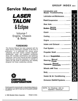
  • 1. &Eclipse GROUP INDEX &ma Service Manual LASER TALON Volume-l Engine, Chassis & Body FOREWORD This Service Manual has been prepared with the latest service information available at the time of ‘* publication. It is subdivided into various group categories and each section contains diagnosis, disassembly, repair, and installation procedures along with complete specifications and tightening references. Use of this manual will aid in properly performing any servicing necessary to maintain or restore the high levels of performance and reliability designed into these outstanding vehicles. 1, w A CHRYSLER CORPORATION Chrysler Corporation reserves the right to make changes in design 0’: to make additions to or improvements in its products without lmqoslng d ., . any obligations upon itself to install them on its products previously manufactured. 0 1990 Mitsubishi Motors Corporation Printed in U.S.A. Introduction and Master Troubleshooting ......,.........r... m , Lubrication and Maintenance . . . . . . . . ‘- 0 ‘8 ; “. i, .Front Suspension . . . . . . . . . . . . . . ..*............d... Rear Axle ..............................‘.................... . / Service Brakes-Parking ...................................... Clutch ................................. ..~...................... ‘t. Cooling . . . . . . . . . . . . . . . . . ..i.................................... ,., .‘, -, Engine ..i....~....r...............~....~.*,.~.~.~,‘~~...;..~~.. Intake and Exhaust . . . . . . ..L.................... Fuel System . . . . . . . . . . . ..ti.......r................~... Propeller Shaft ....................................... I R e a r Suspensiori ......................... ....y.f... Manual Steering- Power ..................................... Manual I transaxle-Automatic .............:;i...,; .... .; Wheels and Tires ................................. Body ............................................................. Heater & Air Conditioning .............. Emission Contr6l Systems .............. INOTE: For Electrical, refer to Volume-2 “Electrical”.
  • 2. 2 INTRODUCTION AND MASTER TROUBLESHOOTING - How to Use This Manual HOW TO USE THIS MANUAL NOaM CONTENTS The preceding page contains GROUP INDEX which lists the group title and group number. PAGE NUMBERS All page numbers consist of two sets of digits separated by a dash. The digits preceding the dash identify the number of the group. The digits follow- ing the dash represent the consecutive page num- ber within the group. The page numbers can be found on the top left or right of each page. TEXT Unless otherwise specified, each service procedure covers all models. Procedures covering specific models are identified by the model codes, or similar designation (engine type, transaxle type, etc.). A description of these designations is covered in this unit under “VEHICLE IDENTIFICATION”. TROUBLESHOOTING Troubleshootings are classified into master trouble- shooting and group troubleshooting and located as follows: The master troubleshooting is prepared when the trouble symptom relates to two or more groups and given in MASTER TROUBLESHOOTING. The group troubleshooting guide is prepared for causes of problems related to that individual group only; a troubleshooting guide is prepared for each appropriate group. LIMIT -9 Shows the standard for judging the quality of a part - or assembly on inspection and,means the maximum or minimum value within which the part or assembly must be kept functionally or in strength. It is a value established outside the range of standard value. Removal steps : The numbers before part name correspond to numbers in the illustration, and indicate the order of removal. Disassembly steps : The numbers before part name correspond to num- bers in the illustration, and indicate the order of disassembly. Installation steps : This is provided if installa- tion cannot’be made in the reverse order of “Removal steps “; omitted if installa- tion in the reverse order of “Removal steps” k possi- ble. Reassembly steps : This is .provided if reas- sembly cannot be made rL+ . . in the reverse order of “Disassembly steps” ; omitted if reassembly in the reverse order of “Dis- assembly steps” is possi- ble. SERVICE PROCEDURES The service steps are arranged in numerical order and attentions to be paid in performing vehicle service are described in detail in SERVICE POINTS. .IVL , -....- ce : Removal l 4 : Installation DEFINITION OF TERMS STANDARD VALUE Indicates the value used as the standard for judging the quality of a part or assembly on inspection or the value to which the part or assembly is corrected and adjusted. It is given by tolerance. MODEL INDICATIONS The following abbreviations are used in this manual for classification of model types. M/T : Indicates the manual transaxle, or models equipped with the manual transaxle. A/T: Indicates the automatic transaxle, or models equipped with the automatic transaxle. MPI: Indicates the multi-point injection, or engines equipped with the multi-point injection. SOHC: Indicates an engine with the single overhead camshaft, or a model equipped with such an engine. DOHC: Indicates an engine with the double overhead camshaft, or a model equipped with such an engine. Turbo: Indicates an engine with turbocharger, or a model equipped with such an engine. Non-Turbo: Indicates an engine without turbocharger, or a model equipped with such an engine. FWD: Indicates the front wheel drive vehicles. AWD: Indicates the all wheel drive vehicles. ABS: Indicates the anti-lock braking system or models equipped with the anti-lock braking system.
  • 3. INTRODUCTION AND MASTER TROUBLESHOOTING - How to Use This Manual 3 Page number Group title I Indicates the incidental operation to be performed before removal or after installa- 524 4 4 BRAKES-Roar Brake Wlmd Cylinder REAR BRAKE WHEEL CYLINDER - - - 3ENjOVAL AND lNSTAU.AllON I I Remwal stepa 1. Brake drum 2. Bleeder screw 3. Brake tube connection l * 4. Wheel cylinder assembly l e 5. Wheel cylinder boot l + 6. Piston assembly n** 7. Piston cue NOTE I1 l Reverse the removal procedures to reinstall. 12) M : Refer to ‘Service Points of Aemcval”. (3) l * : Refer to ‘Service Points of Installation’. 14) q :Nc+-r-reusab(epatts SERWE POINTS REMOVAL’ -7. REMOVAL OF PISTON CUP Using a screwdriver, remove the piston cup from the piston. INSPECTION - Check the following points. and if there is any abnormality, replace the entire wheel cylinder assembly. (1) Check piston and wheel cylinder walls for rust or damage. (2) Check clearance between the cylinder and the piston. Measure in two perpendicular directions to figure the clear- ance between the wheel cylinder inner diameter fmax.value) and the piston outer diameter (minvalue). Limit : 0.15 mm (4059 in.) NOTE If the difference is more than the limit, replace the piston and wheel cylinder as an assembly. This number corresponds to the number in “Removal steps”, “Disassembly steps”, “Installation steps” or “Reassembly steps”.
  • 4. 4 INTRODUCTION AND MASTER TROUBLESHOOTING - How to use This Manual EXPLANATION OF THE TROUBLESHOOTING GUIDE 3. Checking the passenger compartment-temperature sensor, outside-air sensor, air- thermostat sensor and refrigerant-temperature sensor circuits rIndicates the circuit diagram for checking (including the interface of the air conditioner control unit). I I* in the opera- tion descrip- tions only as necessary, and these numbers correspond to the numbers used in har- ness and com- ponent layout l 1 I-- Operation description A negative-characterlstlc thermstor 1s employed for each sensor in order 10 convey the amblent temperature of the sensor pan ,o resistance The sensor power-supply I2 5V) of the awcondltww ““I, IS applied to the lermlnals 116). (15). (17) (5) dlvlded res~~,ance reSlSta”ce R Provides the scription of cir- cuit operation for basic under- standing. I diaarams. Tmublrhooting 4 Dlagnosls No 12 The ou,s,de-a,, sensor ,nput slgnal IS held to 15°C 159°F) No 13 The air-thermostat tensor ~np”t slgnal IS held 10 4°C 139°F) Provides hints (including judgement) when trouble- cedures are fol- lowed. I Terminal I S’g”a’ CO”dl,,O”* Terminal voltage NO I 1 Indicates the diagnosis out- put code No. and the system conditions dur- kng o u t p u t . the conditions un- der which the be made. Indicates the specification to be used for judgement of the check results. If there is no particular men- tion of conditions in the “Conditions” column, the column shows the specifica- tion under normal condi- tions.
  • 5. INTRODUCTION AND MASTER TROUBLESHOOTING - ‘How to use miS .Manual 5 EXPLANATION OF CIRCUIT DIAGRAMS -I The symbols used in circuit diagrams are used as described below. NOTE For detailed information cqncqning the reading of circuit diagrams, refer to GROUP 8-Wi@ng Har- ness. The input/output (dire%% of current flow) relative to the electronic control unit is indicated by symbols (A.m. The (A) symbol indicates that current flows in the upward direction. Output Indicates a connector. IGNITION SWITCH(IG1) Input .A Input/output reht flow is indicat- : ed by the arrow. In this instance, the current flow is in both directions, up The connector symbol indicates the device side connector (for an intermediate con- nector, the male side connector) as seen from the terminal front (the connector’s connection face). c device side con- device side con- L I Indicates the branch point of a harness of a differ- ent line diameter nr line colour. I Indicates that the con- nector is the direct-inser- tion type.
  • 6. 6 INTRODUCTION AND MASTER TROUBLESHOOTING - Vehicle Identificetion VEHICLE IDENTIFICATION Nmx- VEHICLE IDENTIFICATION NUMBER LOCATION The vehicle identification number (V.I.N.) is located oh a plate attached to the left top side of the instrument panel. VEHICLE IDENTIFICATION CODE CHART PLA.4 All vehicle identification numbers contain 17 digits. The vehicle number is a code which tells country, make, vehicle type, etc. 5th Digit r 8th Digit r 9th Digit 11th Digit 12th to 17th Digits 10th Digit Model year M- 1991 Year 7th Digit Body 4- 3 door Hatch- back Engine T- 1.8 liter (107 cu.in.) [SOHC- MPI1 R- 2.0 liters (122 cu.in.) [DOHC- MPI] u- 2.0 liters (122 cuin.) [DOHC- MPI- Turbo] 6th Digit Price class 3- Medium 4- High 5- Premium 6- Special 4th Digit Others B- Manual Seat Belt c- Auto- matic Seat Belt 3rd Digit Vehicle We 3- Passen- ger Car 2nd Digit Make E- Eagle P- Plymouth 1st Digit Country 4- USA Serial number *Check Plant Line E- DSM S- Laser or Talon FWD T- Talon AWD 000001 to 999999 I NOTE * “Check digit” means a single number or letter x used to verify the accuracy of transcription of vehicle identification number.
  • 7. INTRODUCTION AND MASTER TROUBLESHOOTING - Vehicle Identification VEHICLE IDENTIFICATION NUMBER LIST NOOCC-- p, VEHICLES FOR FEDERAL ,.. I V.I.N. (except sequence number) Brand Engine Displacement Models Code ,,; * /./ 4P3CS34aM E Plymouth Laser 1.8 liter (107 cuin.) D21AMNJElXP/RJEL4P’ 4P3CS44aME [SOHC-MPI] D21AMNHEL4P/RHEL4P 4P3CS44ROME 2.0 liter (122 cuin.) [DOHC-MPI] D22AMNHML4P/RHML4P 4P3CS44UuME 2.0 liter (122 cu.in.) [DOHC-MPI-Turbo] D22AMNHFL4P/RHFL4P 4E3CS44ROM E Eap$DTrlon 2.0 liter (122 cu.in.) [DOHC-MPI] D22AMNHML4EIRHML4E 4E3CS54UnME 4E3CT64UOME Eagle Talon <AWD> 2.0 liter (122 cu.in.) [DOHC-MPI-Turbo] D22AMNPFL4EIRPFL4E D27AMNGFL4E/kGFL4E .1 L *, VEHICLES FOR CALIFORNIA V.I.N. (except sequence number) Brand Engine Displacement M o d e l s C o d e 4P3CS34aME Plymouth Laser 1.8 liter (107 cu.in.) D21AMNJELSP/RJELSP 4P3CS44aME [SOHC-MPI] D21AMNHELSP/RHELSP 4P3CS44RmME 2.0 liter (122 cuin.) [DOHC-MPI] D22AMNHMLSP/RHMLSP 4P3CS44UOME 2.0 liter (122 cu.in.1 [DOHC-MPI-Turbo] D22AMNHFLSP/RHFLSP ‘. 4E3CS44RuME Eagle Talon 2.0 liter (122 cu.in.1 <FWD> [DOHC-MPI] D22AMNHMLSE/RHMLSE 4E3CS54UOME 4E3CT64UOME Eagle Talon <AWD> 2.0 liter (122 cu.in.1 [DOHC-MPI-Turbo] D22AMNPFLSElRPFLSE D27AMNGFLSE/RGFLSE VEHICLES FOR CANADA V.I.N. (except sequence number) Brand Engine Displacement Models Code 1’ 1 4P3BS34aME 4P3BS44aME Plymouth Laser 1.8 liter (107 cu.in.1 [SOHC-MPI] D21AMNJEL5P/RJEL5P D21AMNHiL5P/RHEL5P 4P3BS44ROME 2.0 liter (122 cuin.) [DOHC-MPI] D22AMNHML5P/RHML5P 4P3BS44UuME 2.0 liter (122 cu.in.) [DOHC-MPI-Turbo] D22AMNHFL5P/RHFL5P 4E3BS44ROME Eagle Talon 2.0 liter (122 cu.in.) D22AMNHML5EiRHML5E <FWD> [DOHC-MPI] I I 4E3BS54UuME 4E3BT64UnME Eagle Talon <AWD> 2.0 liter (122 cu.in.1 [DOHC-MPI-Turbo]
  • 8. 8 INTRODUCTION AND MASTER TROUBLESHOOTING - Vehicle Identification VEHICLE INFORMATION CODE PLATE NOOCD- Vehicle information code plate is riveted onto the bulkhead in ri the engine compartment. The plate shows model code, engine model, transaxle model, and body color code. 1. MODEL 2. ENGINE 3. TRANSAXLE 4. COLOR, TRIM OPT D22AMN HML4P 2 y$y:/e ‘f$$l 4G63 IEngine model F5M33 y Transaxle model B14 I Monotone exterior color code VEHICLE SAFETY CERTIFICATION LABEL NOOCF- 1. The vehicle safety certification label is attached to the face 2. This label indicates the month and year of manufacture, ;e Gross Vehicle Weight Rating (G.V.W.R.), Gross Axle (G.A.W.R.) front and rear, and Vehicle Identification Number (V.I.N.). ENGINE MODEL STAMPING NOOCG- 1. The engine model number is stamped at the front side on following: Engine model 4637 Engine displacement 1.8 liter (107 cu.in.) [SOHC-MPI] 4G63 2.0 liter (122 cuin.) [DOHC-MPI] or [DOHC-MPI-Turbo] 2. The engine serial number is stamped near the engine model number, and the serial number cycles, as shown below. Engine serial number Number cycling AA0201 t o w9999 AA0201 ------- -*AA99997 I 1 LAB0001 - - - - - - - +AY9999 : 1 I 1 t-BAOOOI - - - - - - - +YY9999 ’ 1 ‘-w
  • 9. INTRODUCTlON AND MASTER TROUBLESHOOTING - Vehicle Identification 9 Theft protection label onginal parts w ,I e IW B ,w w OOA0212 For replacement parts OOA0213 LOCATIONS THEFT PROTECTION NowlAB In order to protect against theft, a Vehicle Identification Number WIN) is stamped in, or attached as a label to, the following major parts of the engine and transaxle, as tiell as main outer panels: Engine cylinder block, Transaxle housing, Fender, Door, Quar- ter panel, Hood, Trunk lid, Bumpers In addition, a theft-protection label is attached to replacement parts for the body outer panel main components, and the same data are stamped into replacement parts for the engine and the transaxle. Cautions regarding panel repairs 1. When repainting original parts, do so after first mask- ing the theft-protection label, and, after painting, be sure to peel off the masking tape. 2. The theft-protection label for replacement parts is covered by masking tape, so such parts can be painted as is. The masking tape should be removed after painting is finished. 3. The theft-protection label should not be removed from original parts or replacement parts. OOA0057 OOA0055
  • 10. Thank you very much for your reading. Please Click Here. Then Get COMPLETE MANUAL. NO WAITING NOTE: If there is no response to click on the link above, please download the PDF document first and then click on it.
  • 11. IO INTRODUCTION AND MASTER TROUBLESHOOTING - Vehicle Identification Part Transaxle Manual transaxle Automatic transaxle Fender The illustration indicates left hand side, outer. 3lA0259 Door 31AO250 - .
  • 12. INTRODUCTION AND MASTER TROUBLESHOOTING - Vehicle Identification 11 Part Quarter panel Target area : for original equipment parts : for replacement parts The label is attached at the inner side of the parts showr in the figure. Hood The illustration indicates left hand side, outer. Right hand side is symmetrically opposite. 31A026E The label is attached at the inner side of the parts shown in the figure. Tailgate 31A0256 The label is attached at the inner side of the parts shown in the figure. 31AO260
  • 13. 12 INTRODUCTION AND MASTER TROUBLESHOOTING - Vehicle Identification Part Front bumper Target area m : for original equipment parts m : for replacement parts Rear bumper The label is attached at the inner side of the parts shown in the figure. 31A0332 The label is attached at the inner side of the parts shown in the figure. 31A0332
  • 14. INTRODUCTION AND MASTER TROUBLESHOOTING - Precautions befdre Service ‘1 S OOV663 OOY192 FOOO 1. FOOO18 0OOD511 J7 PRECAUTIONS BEFORE SERVICE wxww PROTECTING THE VEHICLE If there is a likelihood of damaging painted or interior parts during service operations, protect them with suitable covers (such as seat covers, fender covers, etc.). REMOVAL AND DISASSEMBLY When checking a malfunction, find the cause of the problem. If it is determined that removal and/or disassembly is necessary, perform the work by following the procedures contained in this Service Manual. If punch marks or mating marks are made to avoid error in assembly and to facilitate the assembly work, be sure’to make them in locations which will have no detrimental effect on performance and/or appearances. If an area having many parts, similar parts, and/or parts which are symmetrical right and left is disassembled; be sure to arrange the parts so that they do not become mixed during the assembly process. 1. Arrange the parts removed in the proper order. 2. Determine which parts are to be reused and which are to be replaced. 3. If bolts, nuts, etc., are to be replaced, be sure to use only the exact size specified. i:c ” -,. > ‘. .“i,. i ” ,,‘. 5, SPECIAL TOOLS If other tools are substituted for the special tools to do service or repair work, there is the danger that vehicle parts might be damaged, or the technician might be injured; therefore, be sure to use the special tool whenever doing any work for which the use of one is specified. PARTS TO BE REPLACED If any of the following parts are removed, they must be replaced with new parts. 1. Oil seals 2. Gaskets (except rocker cover gasket) 3. Packings 4. O-rings 5. Lock washers 6. Cotter pins 7. Self-locking nuts