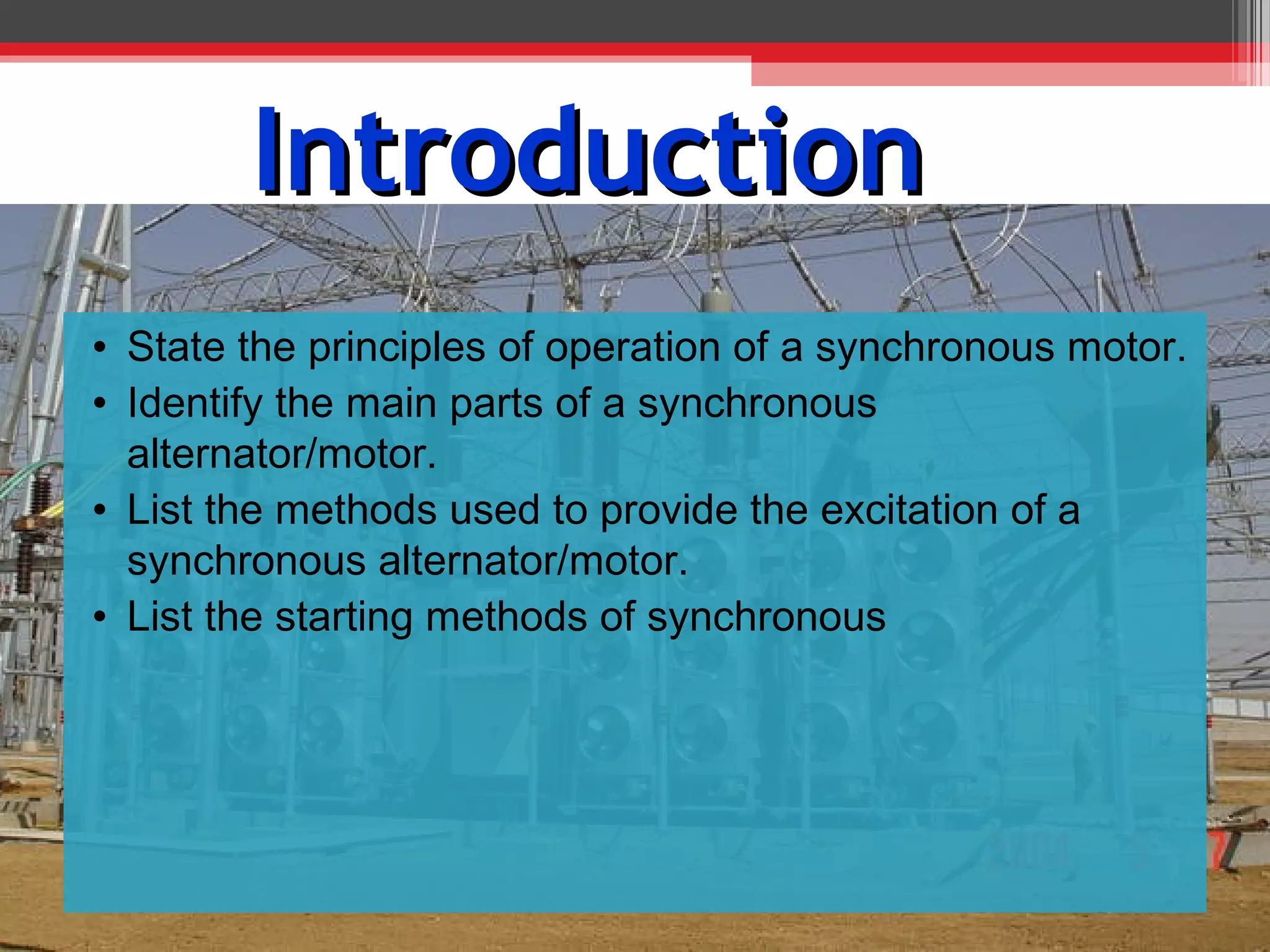
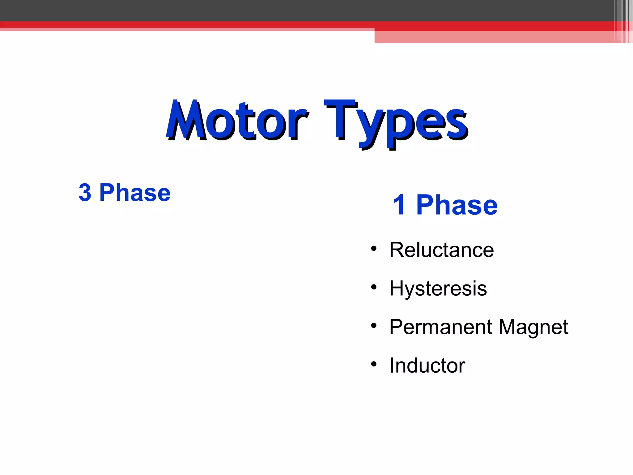
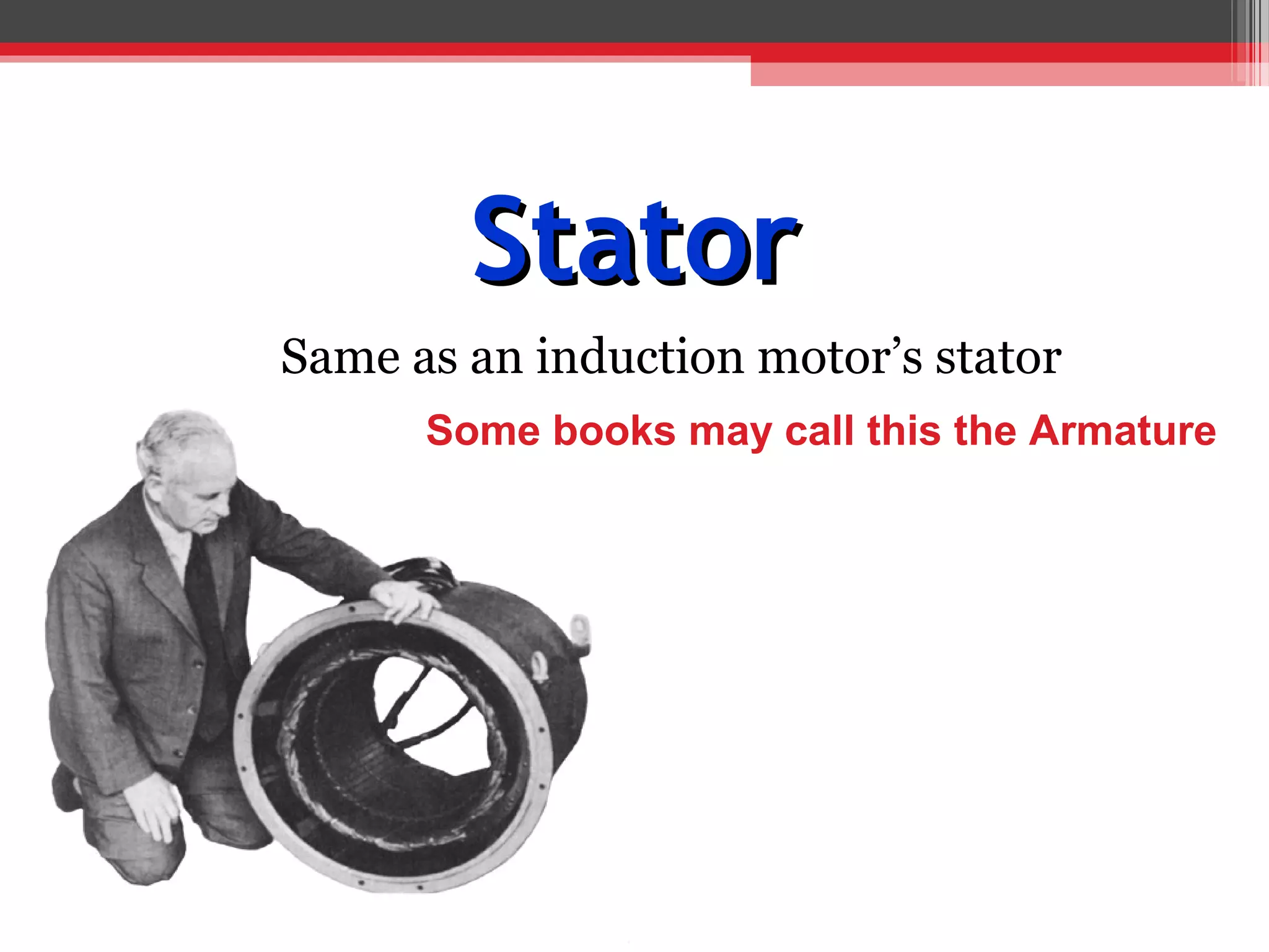
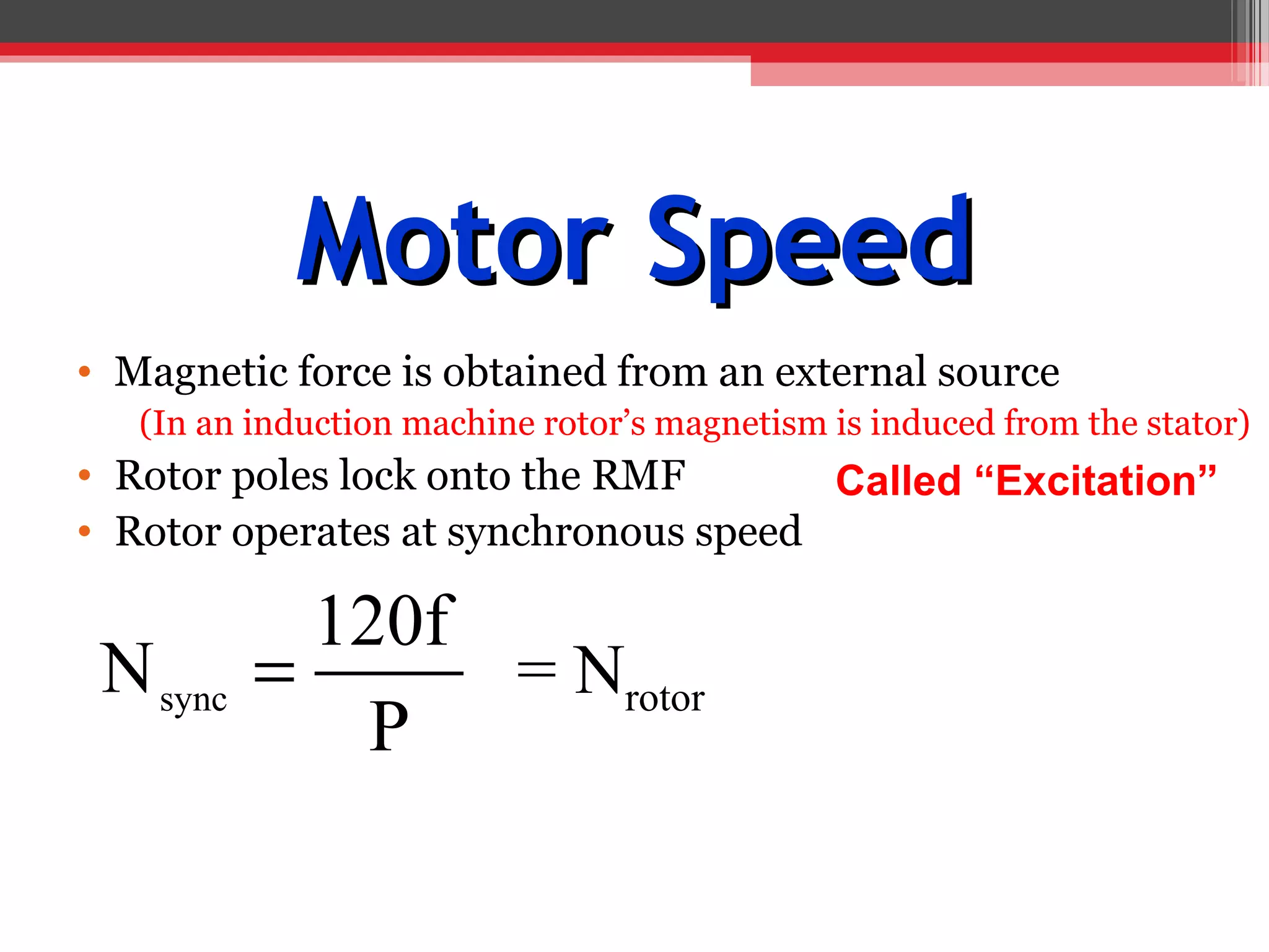
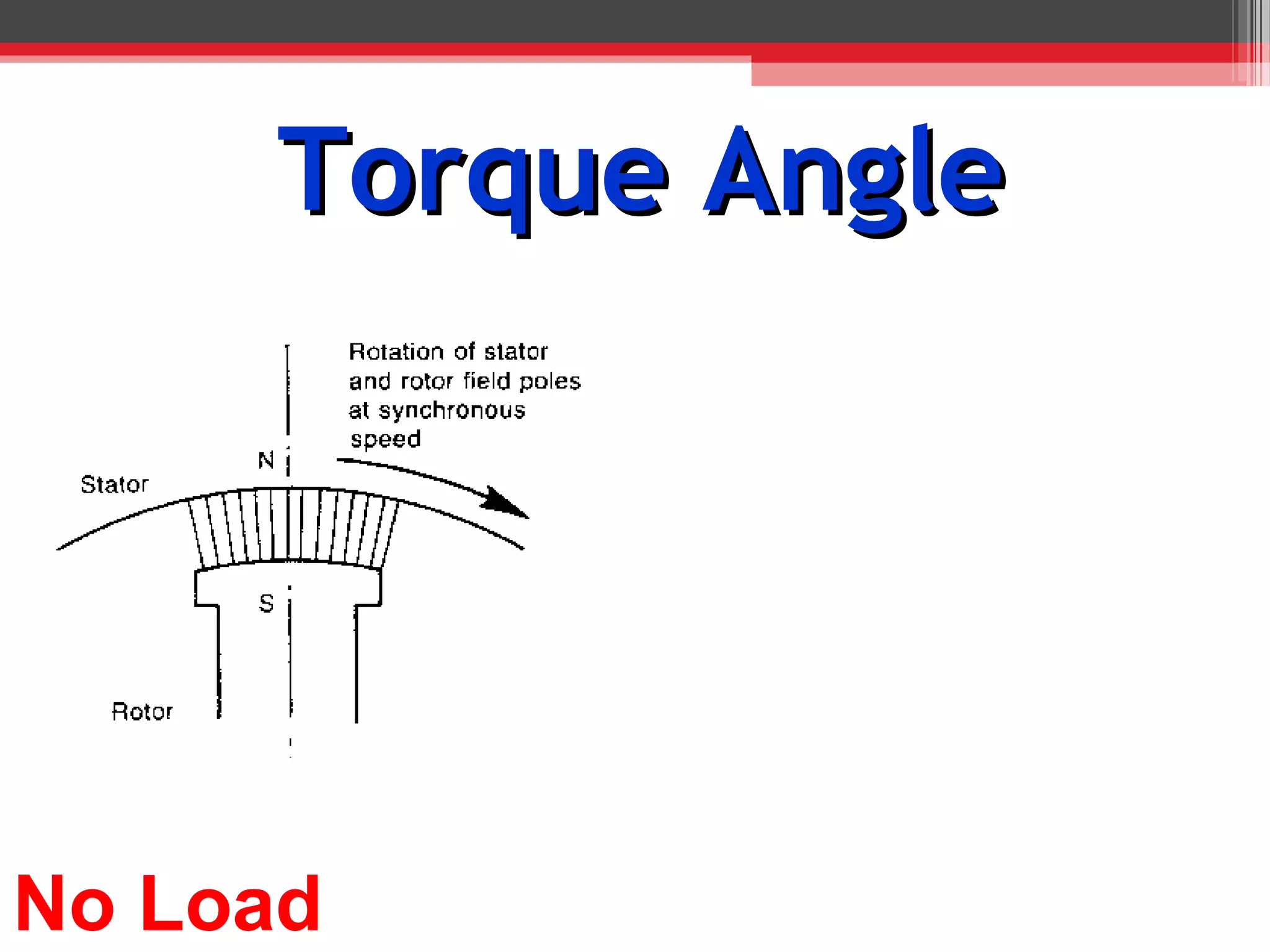
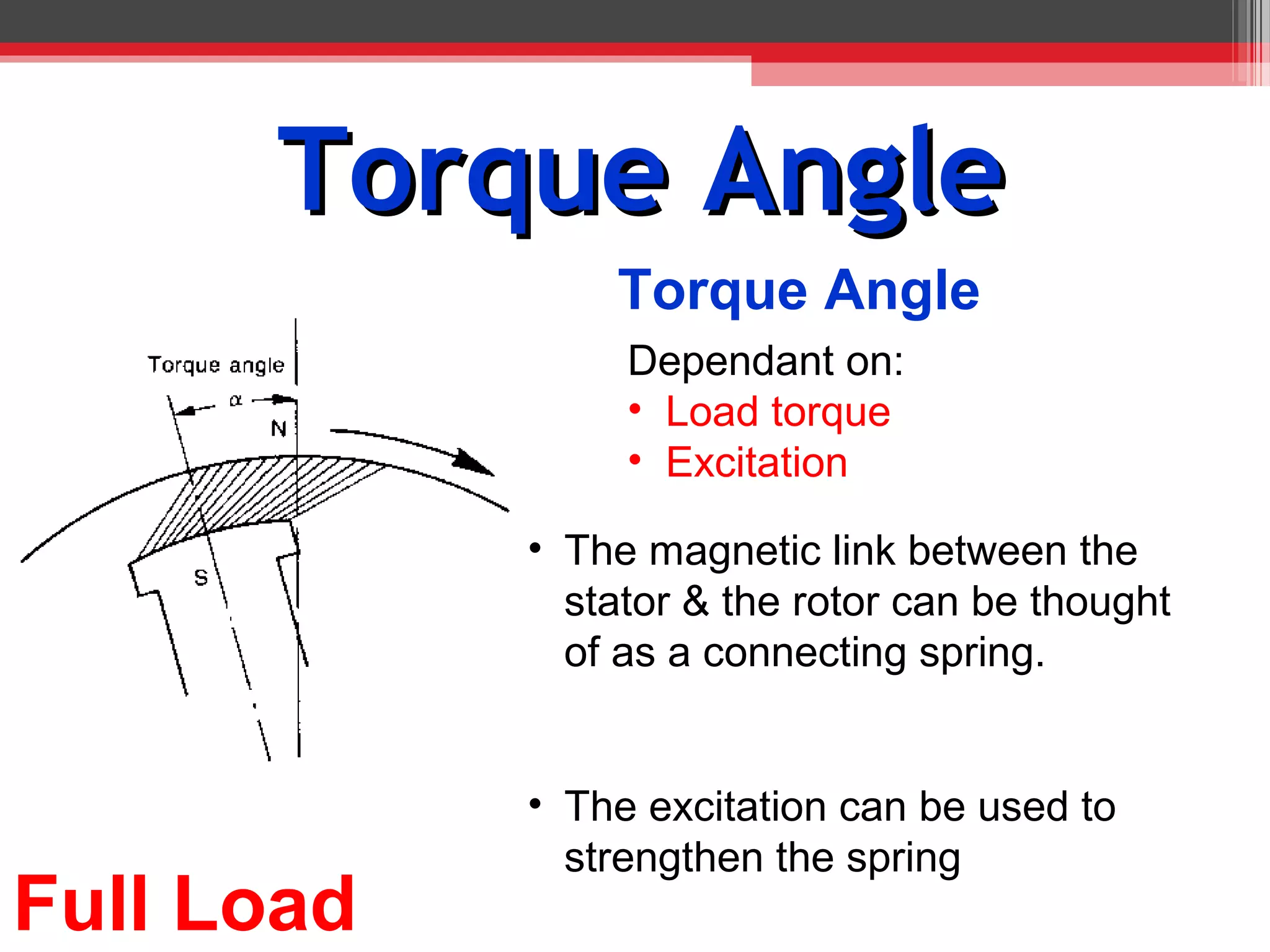
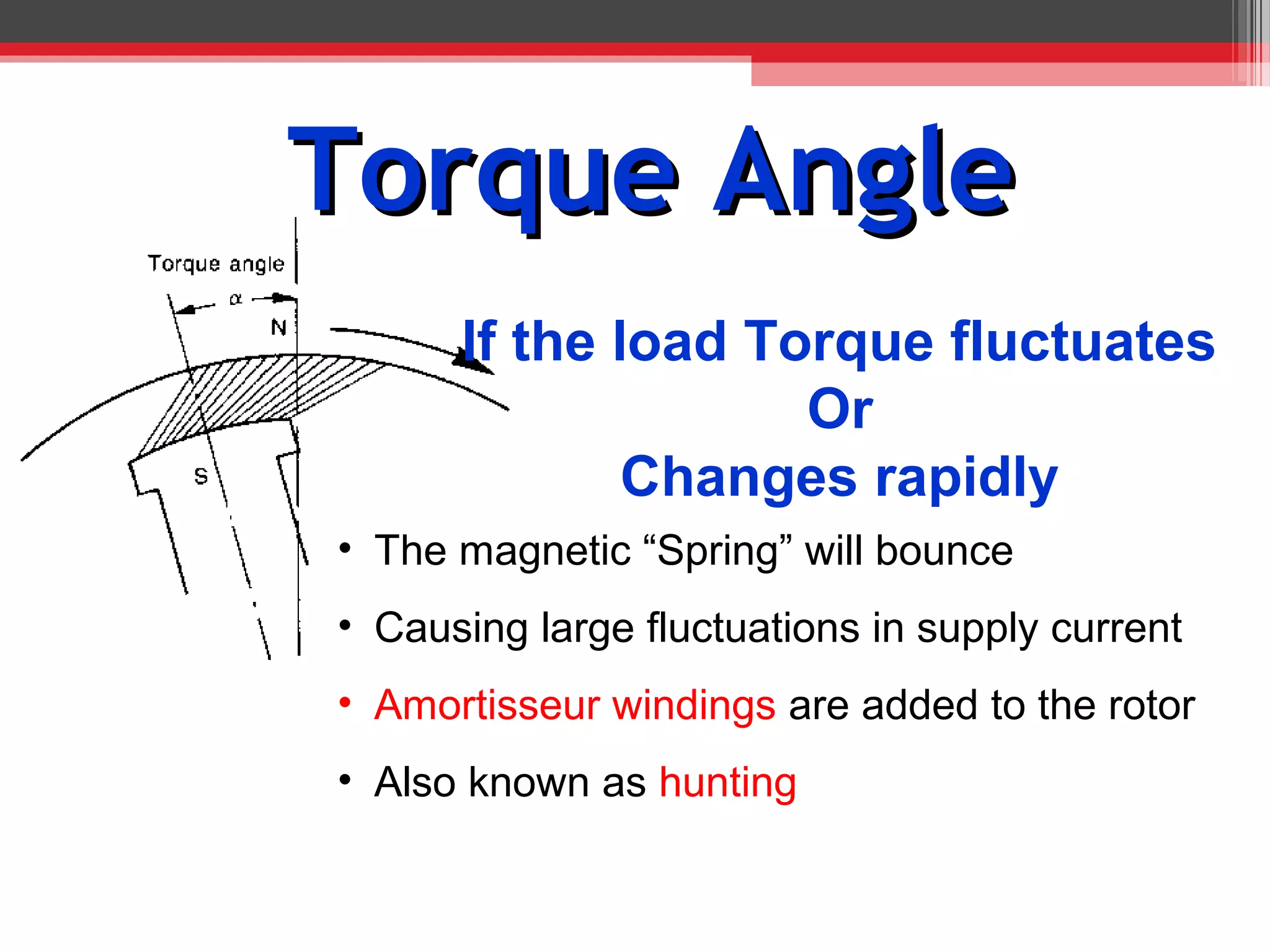
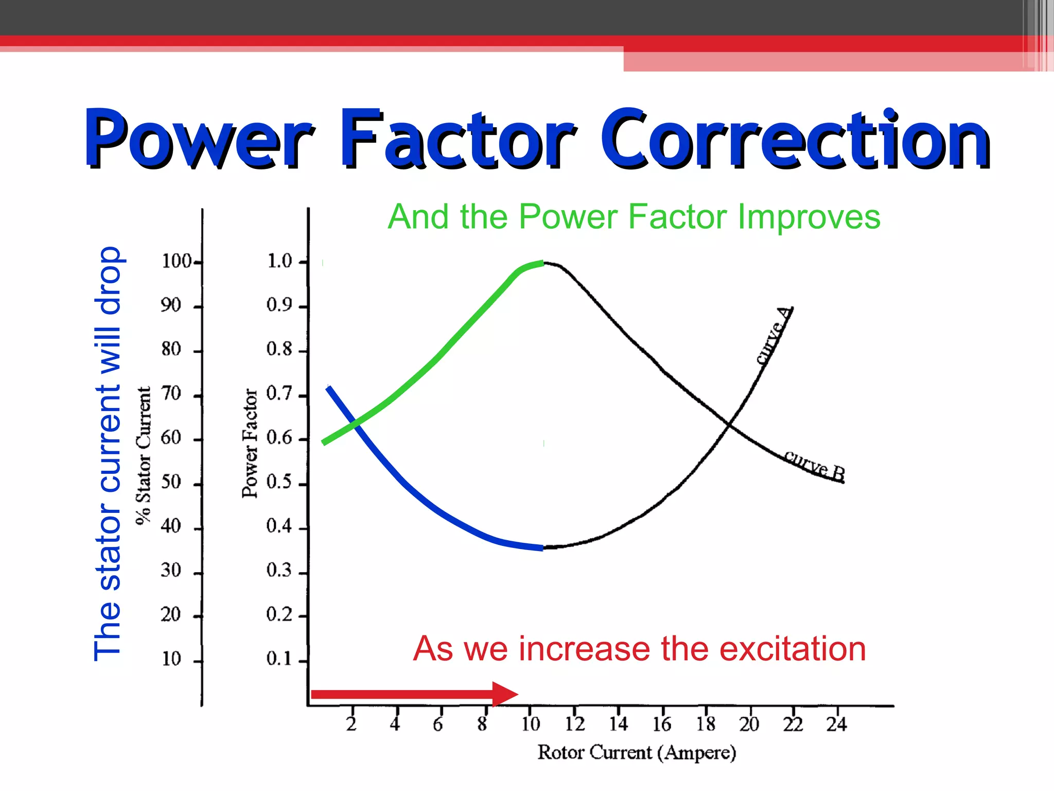
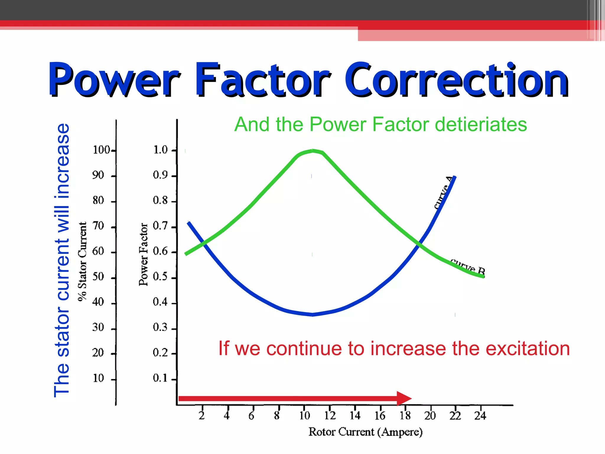
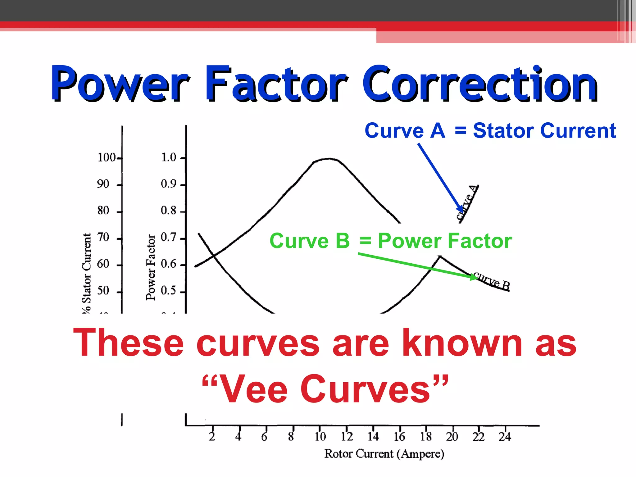
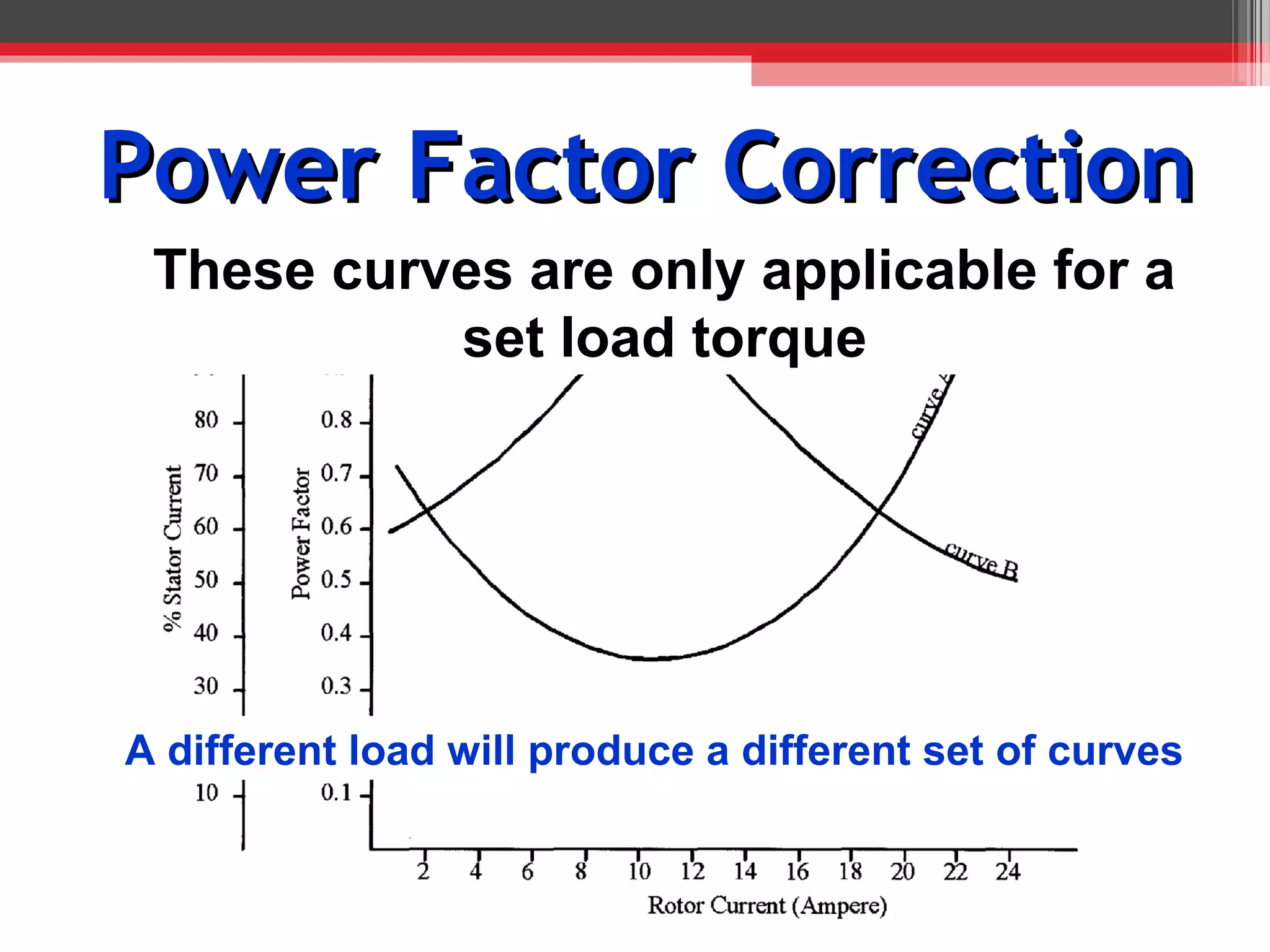
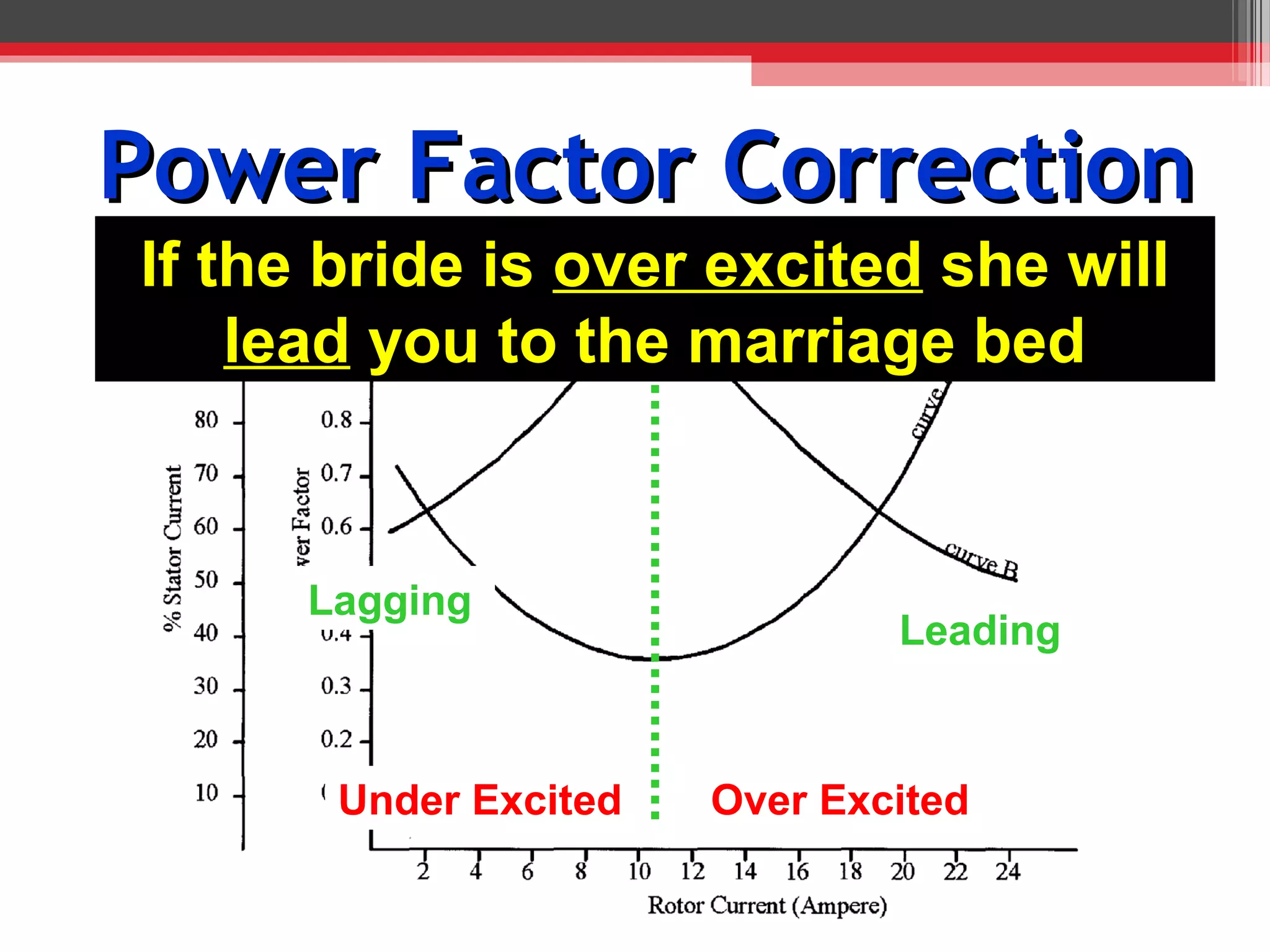
Electrical Machines
 LSEGG216A
 9080V
Synchronous Motors


     Week 14
Introduction
• State the principles of operation of a synchronous motor.
• Identify the main parts of a synchronous
  alternator/motor.
• List the methods used to provide the excitation of a
  synchronous alternator/motor.
• List the starting methods of synchronous
Motor Types
3 Phase
               1 Phase
             • Reluctance
             • Hysteresis
             • Permanent Magnet
             • Inductor
Characteristics
•   High operating efficiency
•   Smooth constant starting & accelerating torque
•   Versatile power factor control
•   Constant speed
•   Considerably more expensive than induction motors
•   Zero starting torque
Stator
Same as an induction motor’s stator
      Some books may call this the Armature
Rotor
• Wound simular to a wound rotor induction motor

• When operating DC voltage is placed across this
  coil to produce an electromagnet

   Some books may call this the Field Windings
Motor Speed
• Magnetic force is obtained from an external source
   (In an induction machine rotor’s magnetism is induced from the stator)
• Rotor poles lock onto the RMF       Called “Excitation”
• Rotor operates at synchronous speed

            120f
 N sync   =      = Nrotor
              P
Torque Angle


No Load
Torque Angle
                Torque Angle
                 Dependant on:
                 • Load torque
                 • Excitation

            • The magnetic link between the
              stator & the rotor can be thought
              of as a connecting spring.


            • The excitation can be used to
              strengthen the spring
Full Load
Torque Angle
      If the load Torque fluctuates
                    Or
              Changes rapidly
• The magnetic “Spring” will bounce
• Causing large fluctuations in supply current
• Amortisseur windings are added to the rotor
• Also known as hunting
Amortisseur Windings
  Similar to the squirrel cage found in induction machines

          Also Known as “Damper “ windings
• When relative movement between the stator and the
  rotor poles occurs

• Voltage is induced into these windings.

• Subsequent induced magnetic field tends to slow
  movement and act like a “shock absorber”

• Can be used to aid starting in a simular way to that of the
  squirrel cage conductors
Starting
Zero starting Torque

   Number of methods:
   • Pony Motor
   • Low Frequency
Pony Motor
                   Starting
An auxiliary smaller motor is used to spin the main motor
up to or near Synchronous speed
Starting
 Low Frequency

• The rotor’s excitation windings are short circuited
• Act like a wound rotor induction motor
• Supply is applied at reduced voltage & frequency
• Rotor builds up speed
• Excitation is then applied to windings and rotor locks in

 Tumit 3 and the Shoalhaven hydro schemes use this system
Motor Uses
• Can be used as a standard motor similar to an
  induction motor
     As an induction machine is cheaper it
     is seldom used just as a motor
• Main use as a power factor correction device
  Sometimes called a rotary capacitor
Power Factor Correction
                               And the Power Factor Improves
The stator current will drop


                                As we increase the excitation
Power Factor Correction
                                    And the Power Factor detieriates
The stator current will increase


                                   If we continue to increase the excitation
Power Factor Correction
                 Curve A = Stator Current


         Curve B = Power Factor


These curves are known as
      “Vee Curves”
Power Factor Correction
 These curves are only applicable for a
           set load torque


A different load will produce a different set of curves
Power Factor Correction
If the bride is over excited she will
                  Unity
    lead you to the marriage bed


      Lagging
                               Leading


       Under Excited   Over Excited
Power Factor Correction
A motor has full load of 100A and an excitation current
of 8A what will be:
• The stator current?
• PF of the motor?
Power Factor Correction
           PF = 0.9 Lagging


                   Stator Current
             38% X 100A = 38A
Example
• A load of 450 kVA operates at a power factor of 0.65
  lagging.
• An additional synchronous motor is added having an
  input power of 90 kW and a maximum power factor of
  0.85 leading.
• Determine reactive power and the overall power factor


 450 x cos 49.5°=
  292.5kW

     49.5°
                    450 x sin 49.5°=
 450kVA
                    342kVar
Example
• A load of 450 kVA operates at a power factor of 0.65
  lagging.
• An additional synchronous motor is added having an
  input power of 90 kW and a maximum power factor of
  0.85 leading.
• Determine reactive power and the overall power factor
                                           tan-1 x 286/382.5 = 36.8°
              292.5 + 90 =    382.5kW
                                             PF =    0.8 Lag
                               90 x tan 31.8° =
  292.5kW             31.8°     55.8kVar
                                             342 – 55.8 = 286kVar
    49.5°         90kW

 450kVA
                  342kVar

14+synchronous+motors

  • 1.
  • 2.
  • 3.
    Introduction • State theprinciples of operation of a synchronous motor. • Identify the main parts of a synchronous alternator/motor. • List the methods used to provide the excitation of a synchronous alternator/motor. • List the starting methods of synchronous
  • 4.
    Motor Types 3 Phase 1 Phase • Reluctance • Hysteresis • Permanent Magnet • Inductor
  • 5.
    Characteristics • High operating efficiency • Smooth constant starting & accelerating torque • Versatile power factor control • Constant speed • Considerably more expensive than induction motors • Zero starting torque
  • 6.
    Stator Same as aninduction motor’s stator Some books may call this the Armature
  • 7.
    Rotor • Wound simularto a wound rotor induction motor • When operating DC voltage is placed across this coil to produce an electromagnet Some books may call this the Field Windings
  • 8.
    Motor Speed • Magneticforce is obtained from an external source (In an induction machine rotor’s magnetism is induced from the stator) • Rotor poles lock onto the RMF Called “Excitation” • Rotor operates at synchronous speed 120f N sync = = Nrotor P
  • 9.
  • 10.
    Torque Angle Torque Angle Dependant on: • Load torque • Excitation • The magnetic link between the stator & the rotor can be thought of as a connecting spring. • The excitation can be used to strengthen the spring Full Load
  • 11.
    Torque Angle If the load Torque fluctuates Or Changes rapidly • The magnetic “Spring” will bounce • Causing large fluctuations in supply current • Amortisseur windings are added to the rotor • Also known as hunting
  • 12.
    Amortisseur Windings Similar to the squirrel cage found in induction machines Also Known as “Damper “ windings • When relative movement between the stator and the rotor poles occurs • Voltage is induced into these windings. • Subsequent induced magnetic field tends to slow movement and act like a “shock absorber” • Can be used to aid starting in a simular way to that of the squirrel cage conductors
  • 13.
    Starting Zero starting Torque Number of methods: • Pony Motor • Low Frequency
  • 14.
    Pony Motor Starting An auxiliary smaller motor is used to spin the main motor up to or near Synchronous speed
  • 15.
    Starting Low Frequency •The rotor’s excitation windings are short circuited • Act like a wound rotor induction motor • Supply is applied at reduced voltage & frequency • Rotor builds up speed • Excitation is then applied to windings and rotor locks in Tumit 3 and the Shoalhaven hydro schemes use this system
  • 16.
    Motor Uses • Canbe used as a standard motor similar to an induction motor As an induction machine is cheaper it is seldom used just as a motor • Main use as a power factor correction device Sometimes called a rotary capacitor
  • 17.
    Power Factor Correction And the Power Factor Improves The stator current will drop As we increase the excitation
  • 18.
    Power Factor Correction And the Power Factor detieriates The stator current will increase If we continue to increase the excitation
  • 19.
    Power Factor Correction Curve A = Stator Current Curve B = Power Factor These curves are known as “Vee Curves”
  • 20.
    Power Factor Correction These curves are only applicable for a set load torque A different load will produce a different set of curves
  • 21.
    Power Factor Correction Ifthe bride is over excited she will Unity lead you to the marriage bed Lagging Leading Under Excited Over Excited
  • 22.
    Power Factor Correction Amotor has full load of 100A and an excitation current of 8A what will be: • The stator current? • PF of the motor?
  • 23.
    Power Factor Correction PF = 0.9 Lagging Stator Current 38% X 100A = 38A
  • 24.
    Example • A loadof 450 kVA operates at a power factor of 0.65 lagging. • An additional synchronous motor is added having an input power of 90 kW and a maximum power factor of 0.85 leading. • Determine reactive power and the overall power factor 450 x cos 49.5°= 292.5kW 49.5° 450 x sin 49.5°= 450kVA 342kVar
  • 25.
    Example • A loadof 450 kVA operates at a power factor of 0.65 lagging. • An additional synchronous motor is added having an input power of 90 kW and a maximum power factor of 0.85 leading. • Determine reactive power and the overall power factor tan-1 x 286/382.5 = 36.8° 292.5 + 90 = 382.5kW PF = 0.8 Lag 90 x tan 31.8° = 292.5kW 31.8° 55.8kVar 342 – 55.8 = 286kVar 49.5° 90kW 450kVA 342kVar