This document discusses synchronous motors and provides information on:
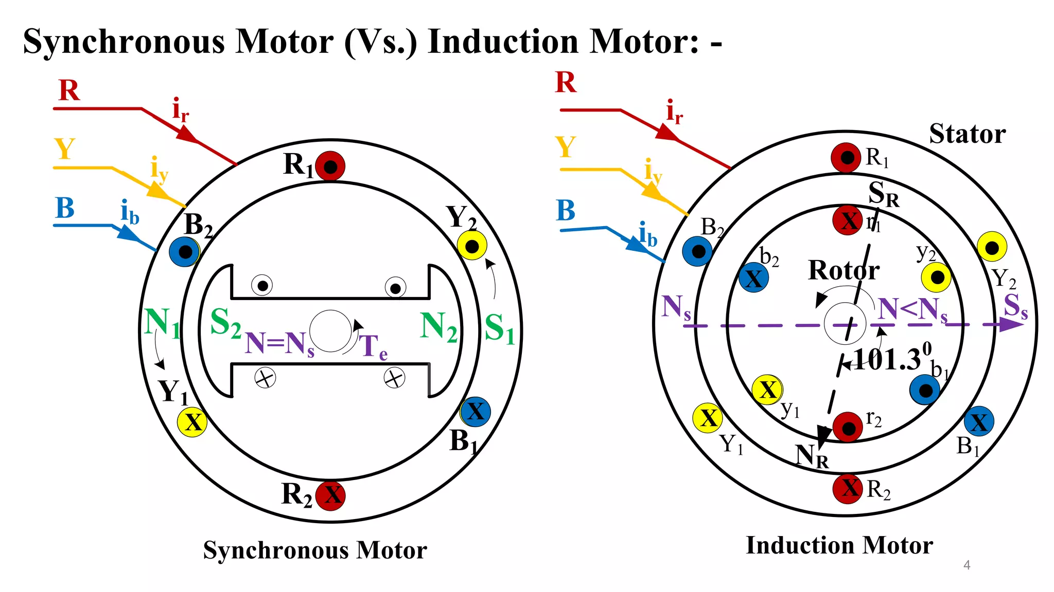
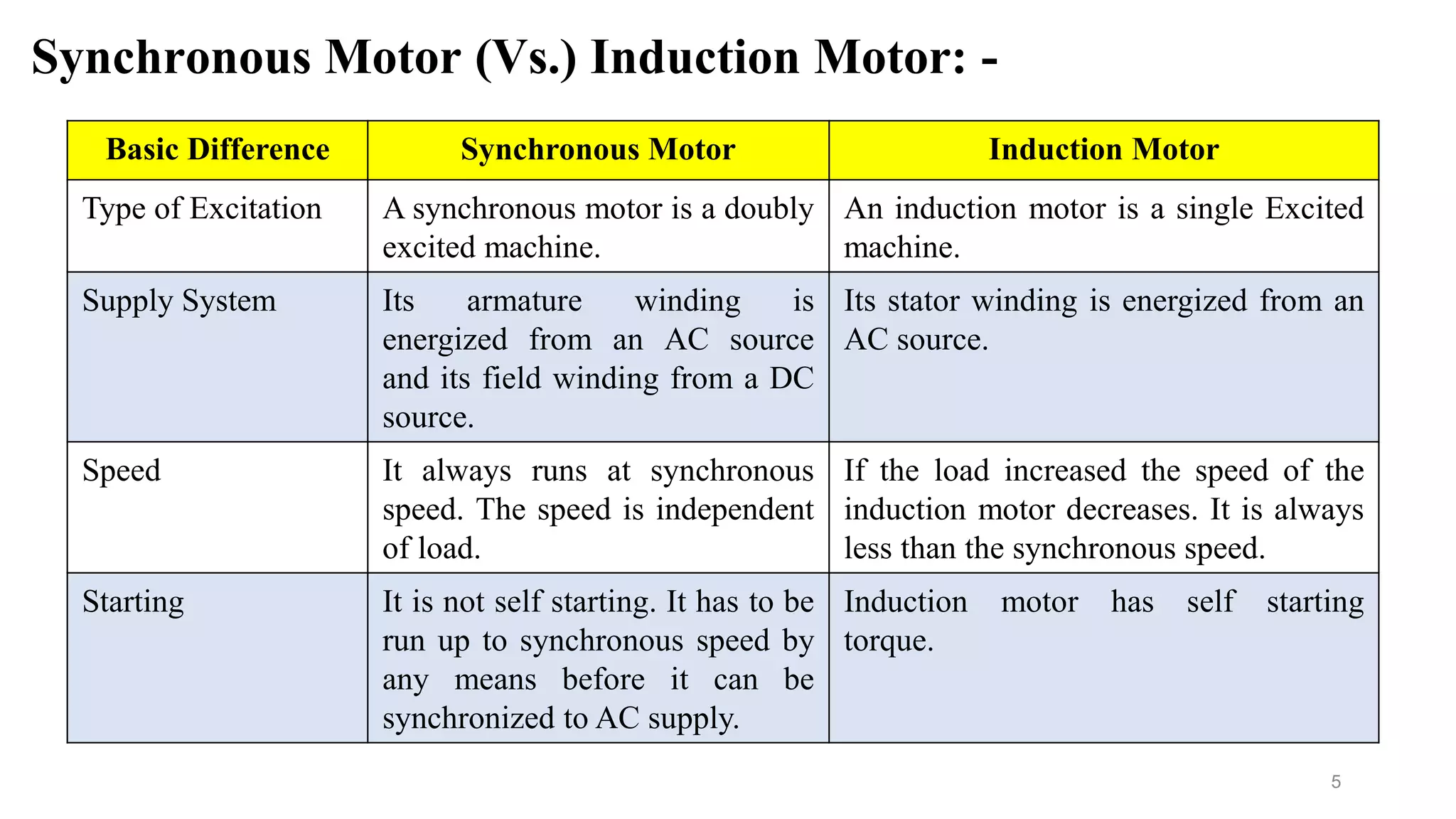
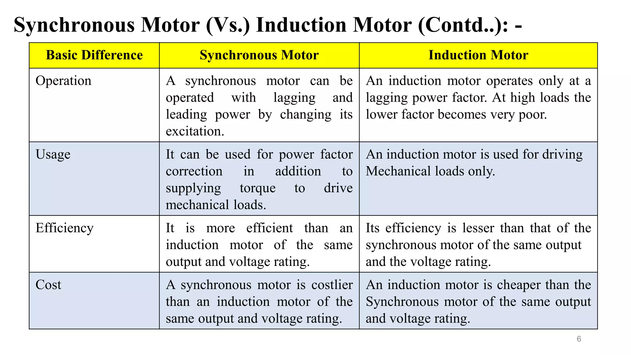
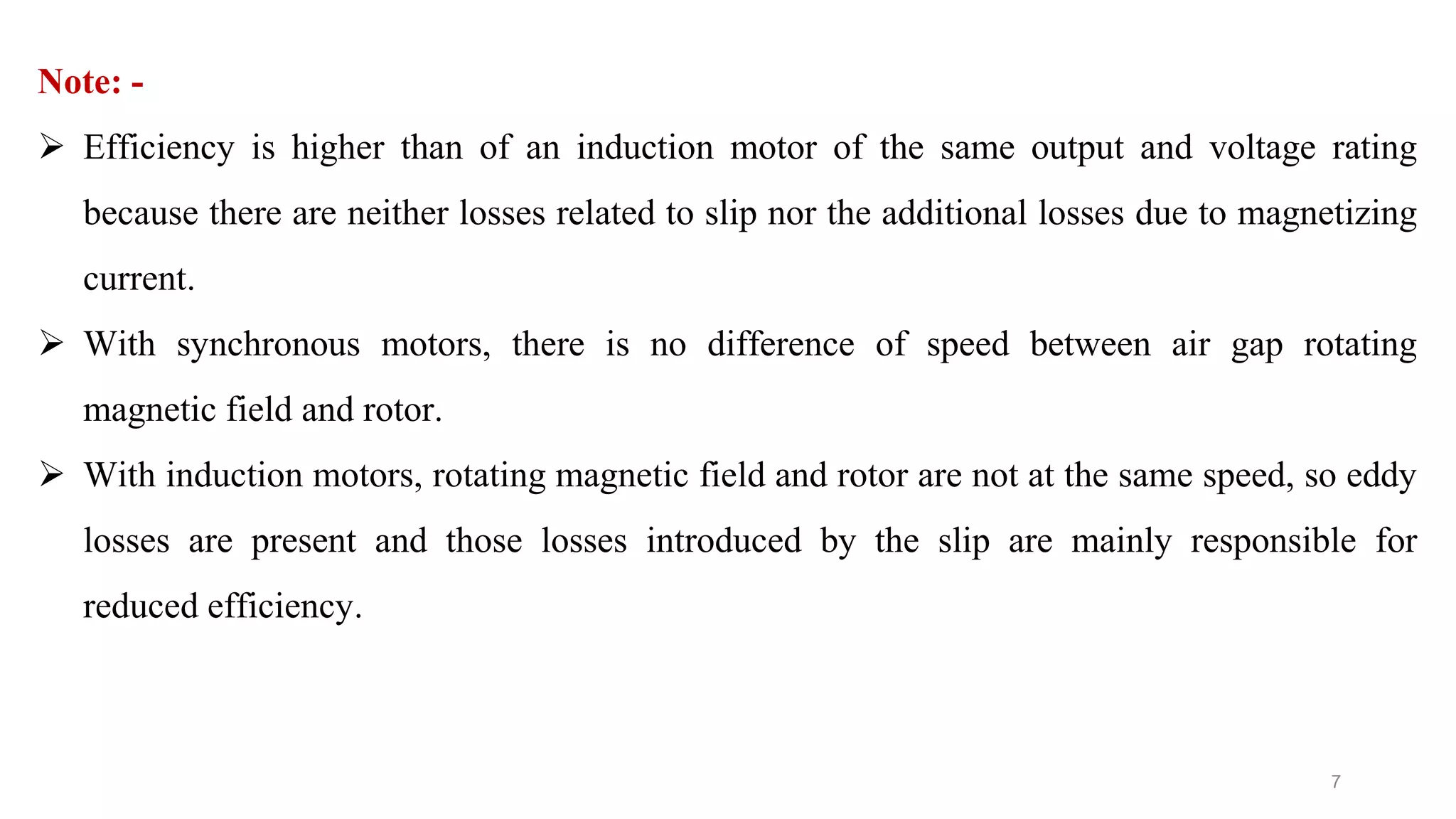
- The key differences between synchronous motors and induction motors, including excitation type, speed, starting capability, and efficiency.
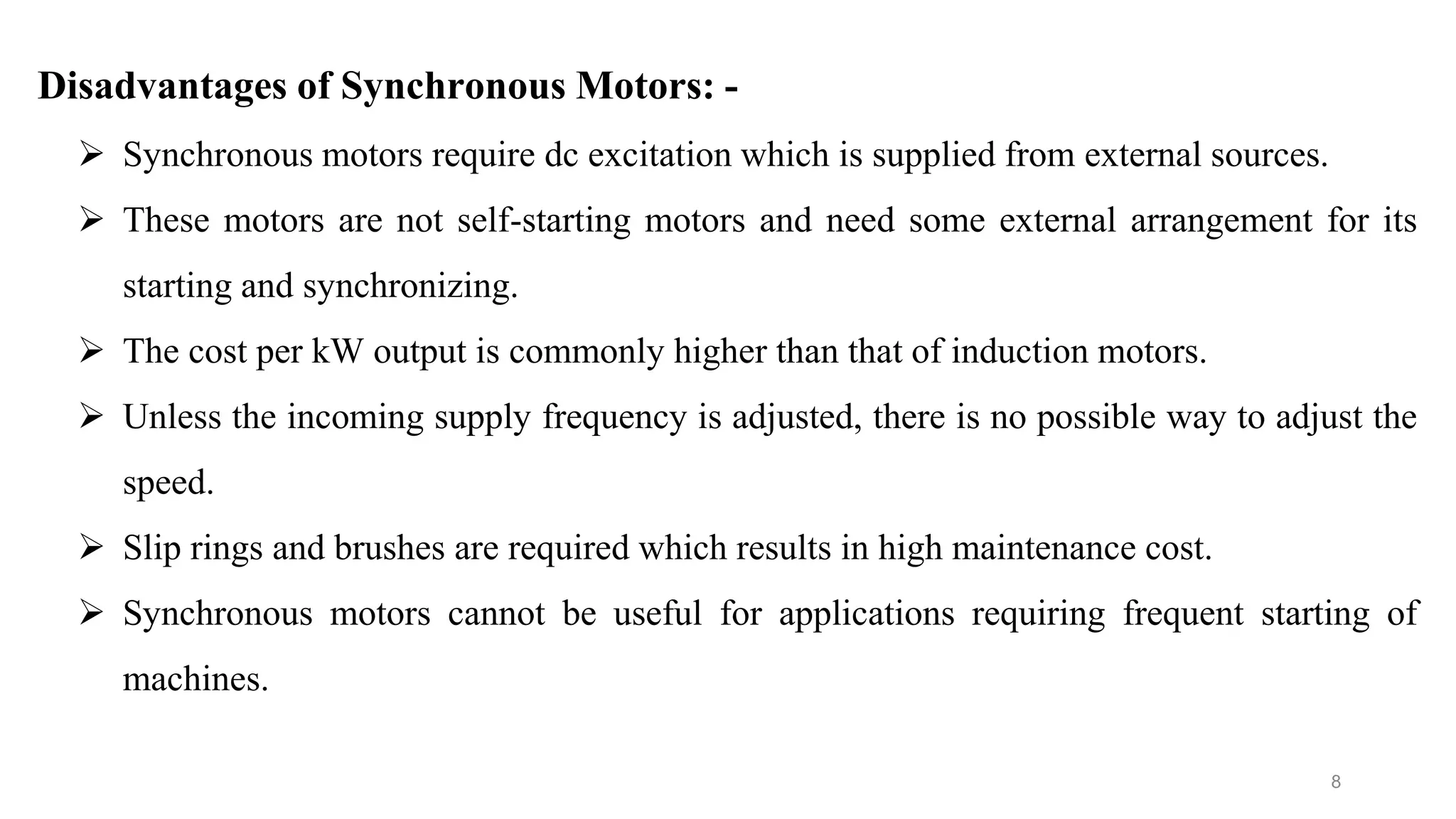
- The advantages of synchronous motors such as ability to operate at lagging or leading power factor and disadvantages like higher cost and need for external excitation.
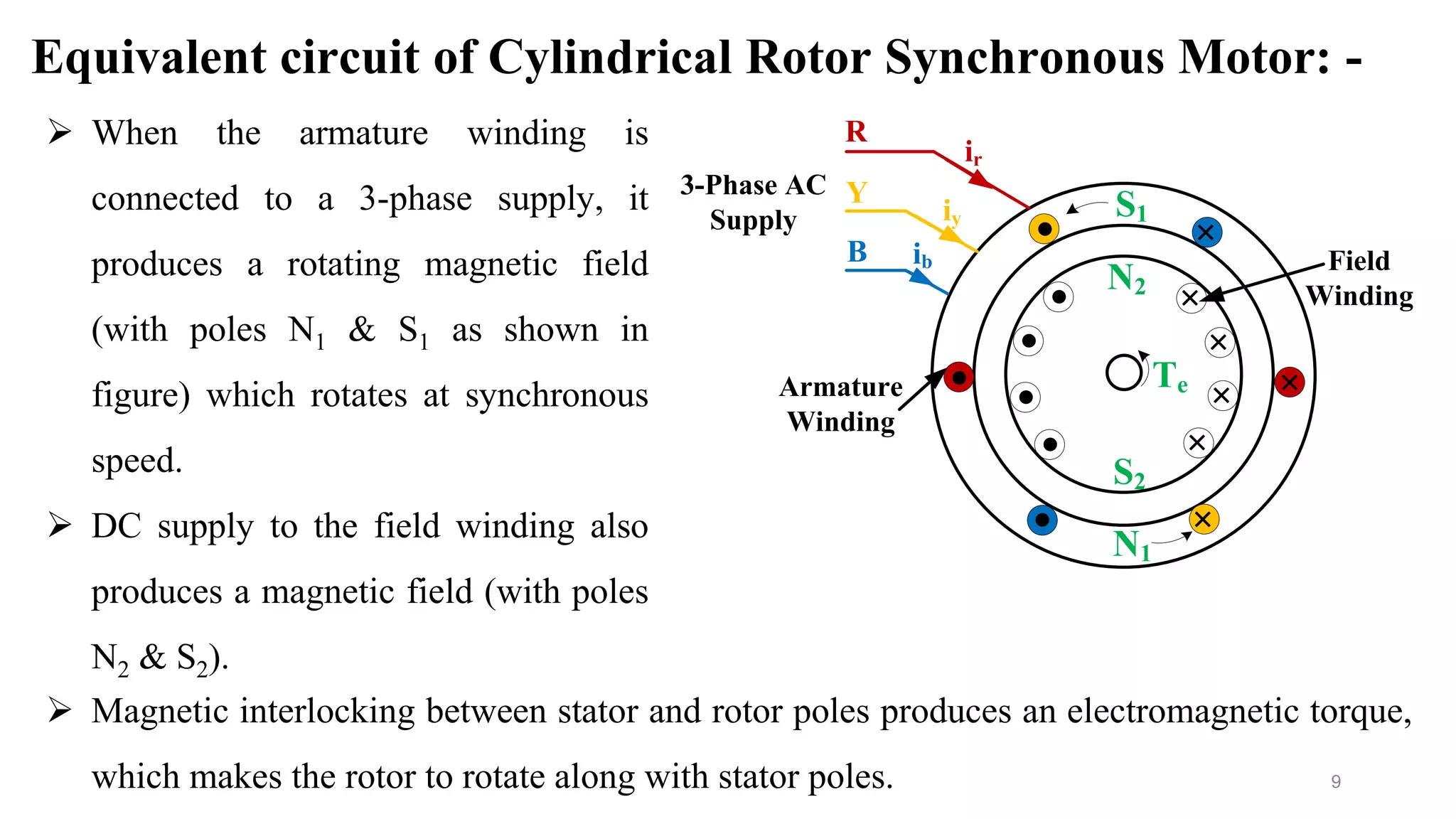
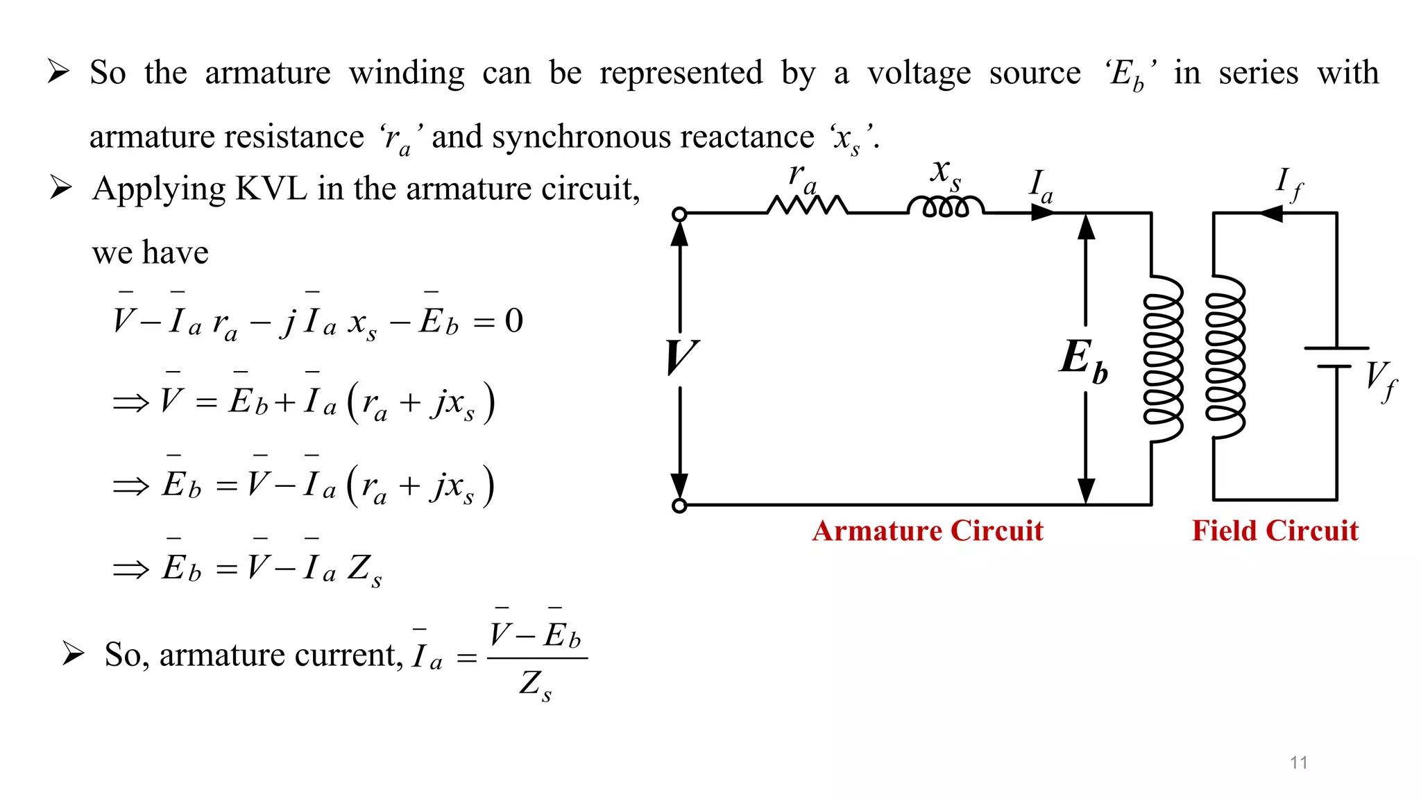
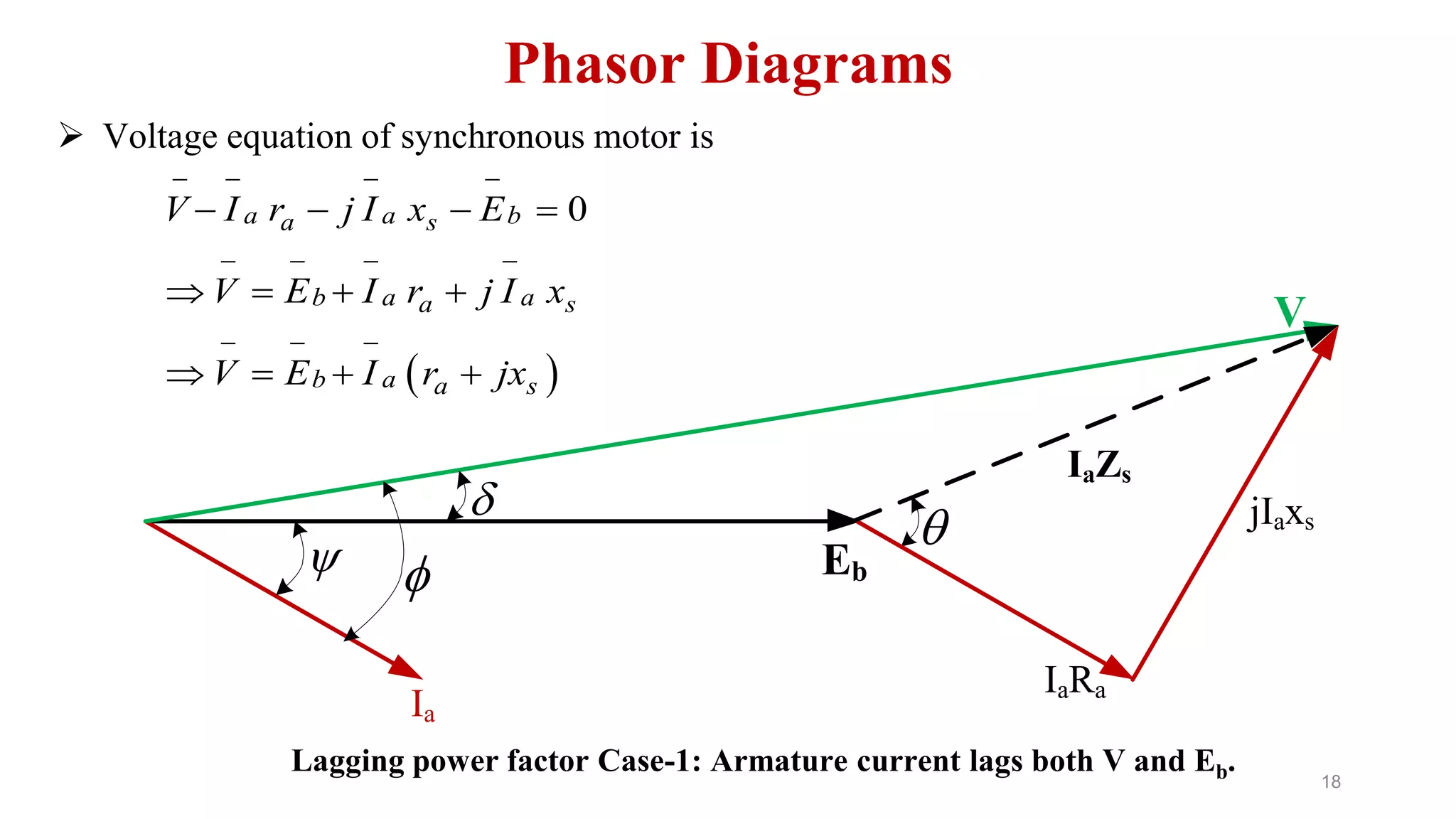
- The equivalent circuit model of a cylindrical rotor synchronous motor and voltage equation.
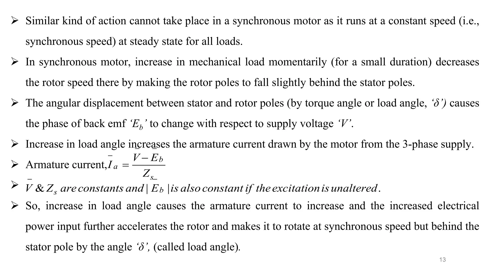
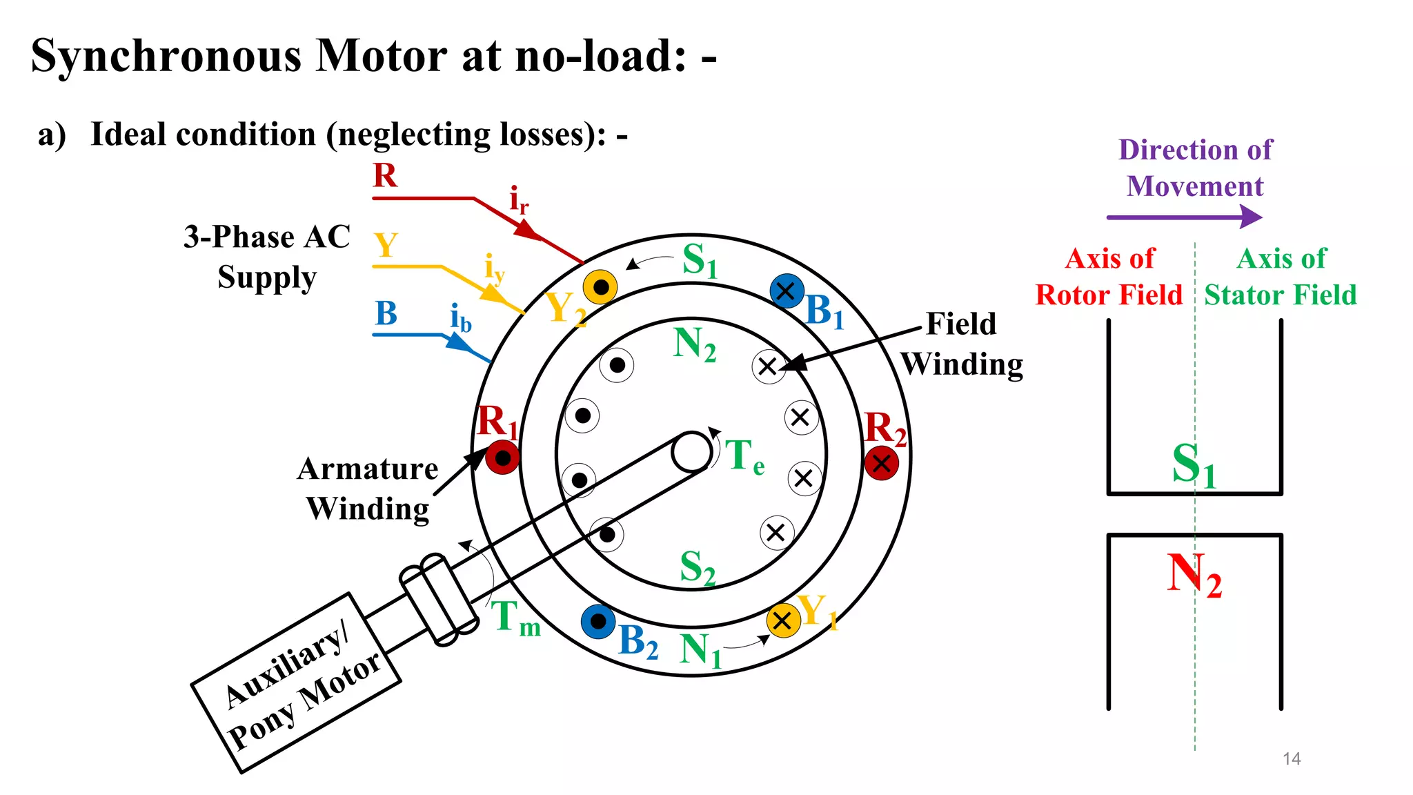
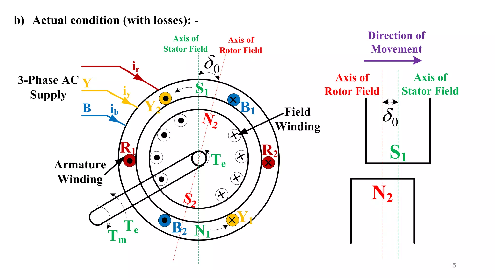
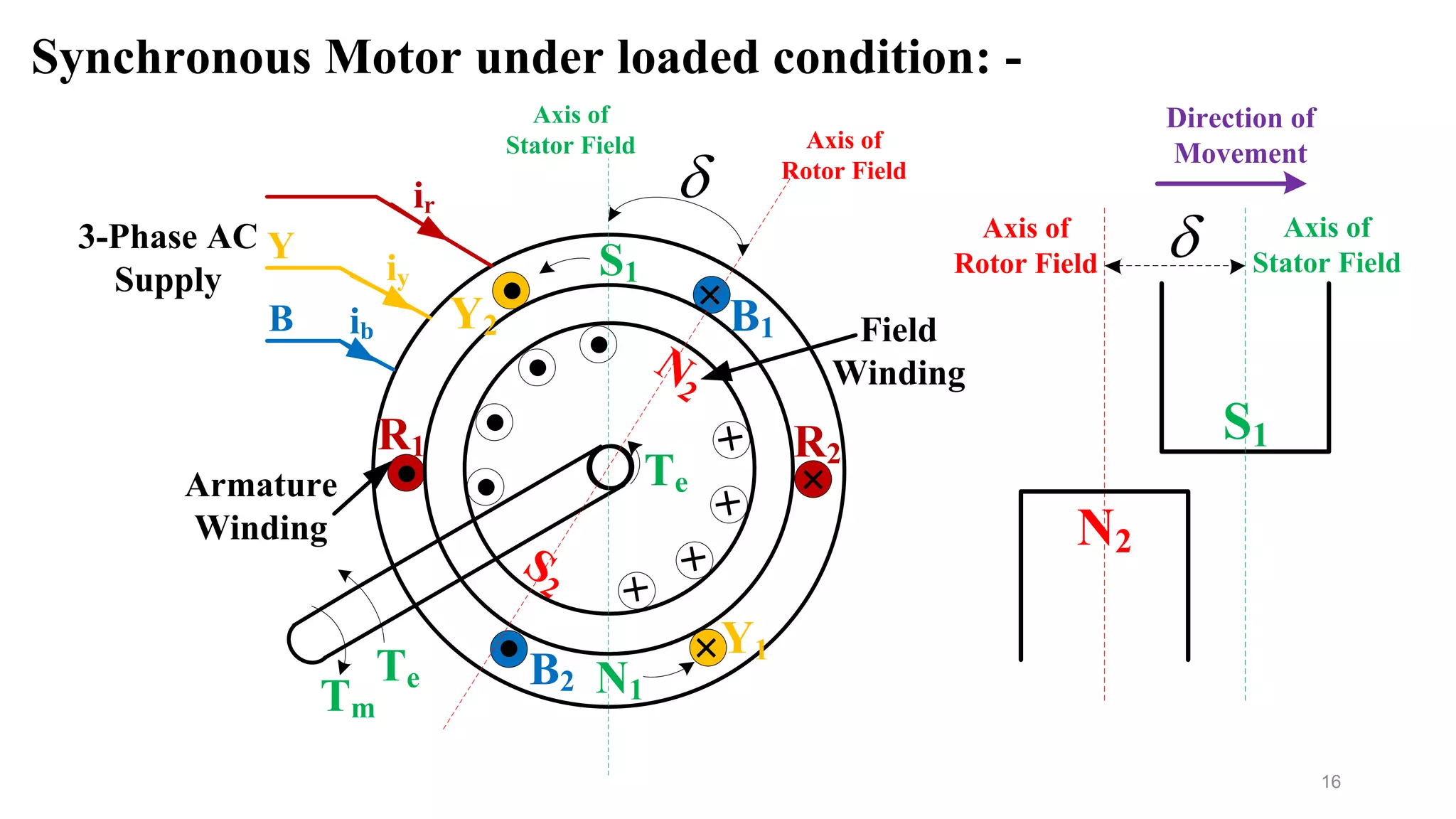
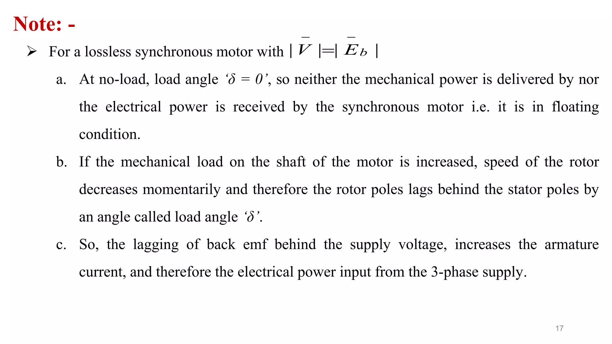
- The operation of a synchronous motor at no load and under loaded conditions, explaining how an increase in load causes the rotor to lag the stator by the load angle to draw more current.
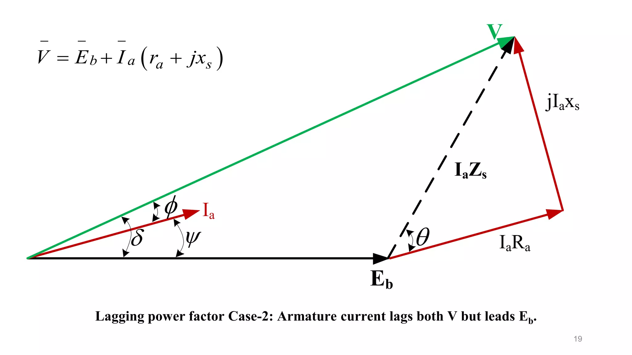
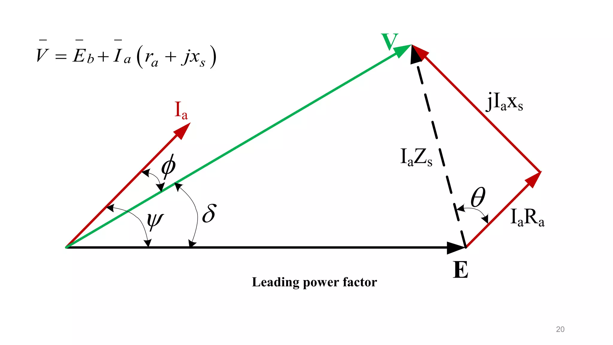
- Phasor diagrams showing the voltage and current relationships under lagging and leading power factor operation.
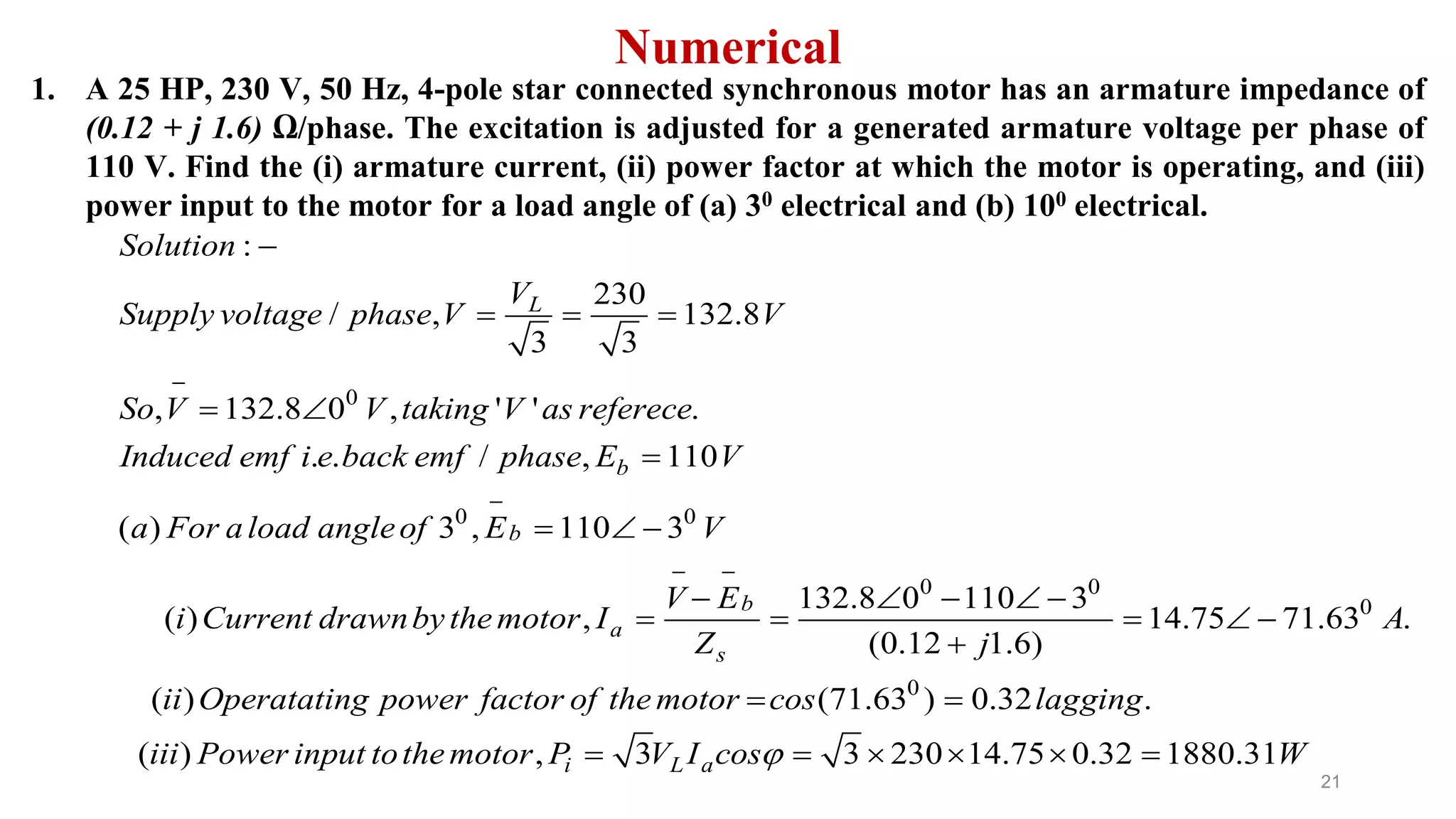
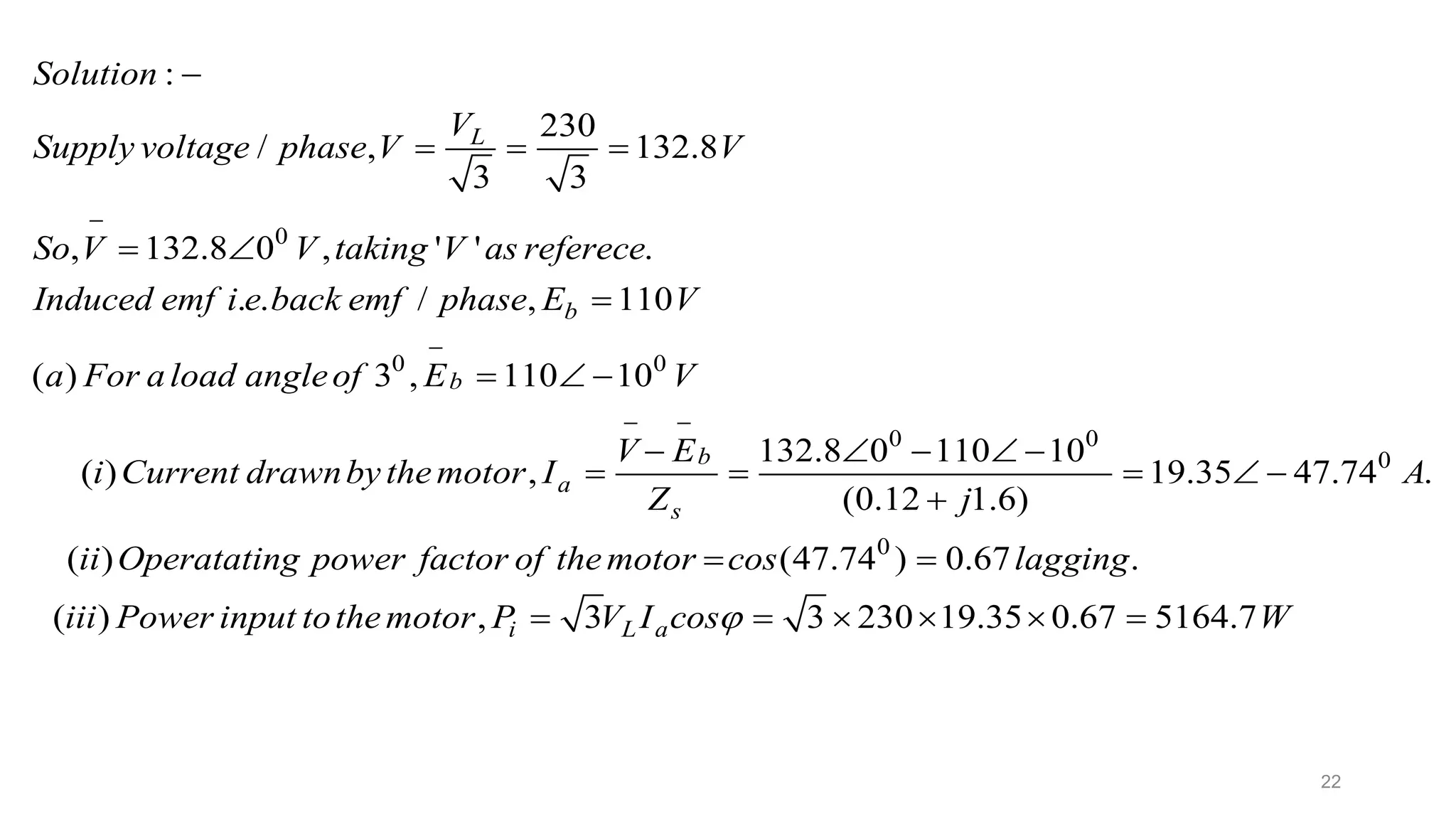
- An example numerical