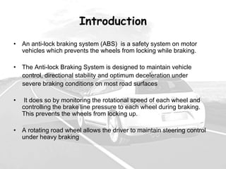
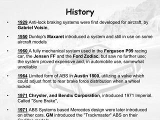
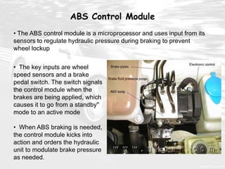
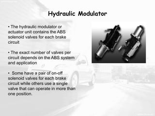
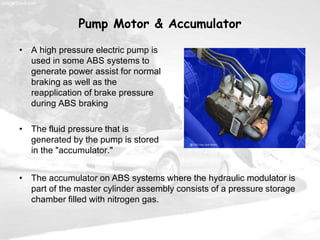
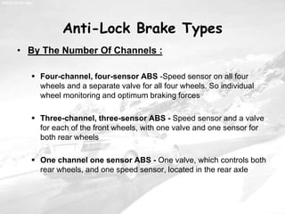
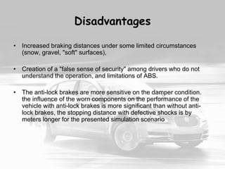
Seminar by ;-
Mr. SWAPNIL B. KUDACHE
Mr. SANKET A. PATIL
Mr. AVINASH S. PATIL
Mr. AVINASH A. SHENDE
Anti Locking Brakes
Introduction
• An anti-lock braking system (ABS) is a safety system on motor
vehicles which prevents the wheels from locking while braking.
• The Anti-lock Braking System is designed to maintain vehicle
control, directional stability and optimum deceleration under
severe braking conditions on most road surfaces
• It does so by monitoring the rotational speed of each wheel and
controlling the brake line pressure to each wheel during braking.
This prevents the wheels from locking up.
• A rotating road wheel allows the driver to maintain steering control
under heavy braking
History
• 1929 Anti-lock braking systems were first developed for aircraft, by
Gabriel Voisin,
• 1950 Dunlop's Maxaret introduced a system and still in use on some
aircraft models
• 1960 A fully mechanical system used in the Ferguson P99 racing
car, the Jensen FF and the Ford Zodiac, but saw no further use;
the system proved expensive and, in automobile use, somewhat
unreliable
• 1964 Limited form of ABS in Austin 1800, utilizing a valve which
could adjust front to rear brake force distribution when a wheel
locked
• 1971 Chrysler, and Bendix Corporation, introduced 1971 Imperial.
Called "Sure Brake",
• 1971 ABS Systems based Mercedes design were later introduced
on other cars. GM introduced the "Trackmaster" ABS on their
• 1975 Ford also introduced ABS on the Lincoln Continental Mark III
and the Ford LTD station wagon, called "Sure Trak
• 1978 Bosch and Mercedes-Benz introduced the first completely
electronic 4-wheel multi-channel ABS system in trucks and the
Mercedes-Benz S-Class
• 1988 BMW became the world's first motorcycle manufacturer to
introduce an electronic/hydraulic ABS system, this on their BMW
K100
• 1992 Honda launched its first ABS system, this on the ST1100 Pan
European
• 1997 Suzuki launched its GSF1200SA (Bandit) with ABS
• Today ABS has become a standard equipment even for small cars
Theory
• When the car brakes (normally ) wheels exert a forward
force on the street which less than maximum static sliding
friction
• If the driver brakes very hard it can occur that the maximum
static friction is surpassed and the wheels lose their grip and begin
sliding
• The amount of traction
which can be obtained for
an auto tire is determined
by the coefficient of static
friction between the tire
and the road. If the wheel
is locked and sliding, the
force of friction is
determined by the
coefficient of kinetic friction
• A tire that is just on the verge of slipping produces more friction
with respect to the road than one which is locked and skidding . So
locked wheels are less effective in stopping on a road
• When tire does not slip, it will
roll only in the direction it turns. But
once it skids, regardless of the
angle of the front wheels, the
vehicle continues to skid in
whatever direction its momentum
sends it until either the driver
releases the brakes
But in gravel, sand and deep
snow, locked wheels dig in and
stop the vehicle more quickly. A
locked tire allows a small wedge
of snow to build up ahead of it
which allows it to stop in a
somewhat shorter distance than
a rolling tire.
• The Anti-lock Braking System is designed to maintain vehicle
control, directional stability and optimum deceleration under
severe braking conditions on most road surfaces
Basic Operation
• It does so by
monitoring the
rotational speed
of each wheel
and controlling
the brake line
pressure to
each wheel
during braking.
This prevents
the wheels from
locking up.
• When a wheel is
about to lock up,
the control unit
signals the
hydraulic unit to
reduce hydraulic
pressure (or not
increase it further)
at that wheel’s
brake caliper.
Pressure
modulation is
handled by
electrically-
operated solenoid
valves
 The sensors - one at each wheel send a variable voltage signal
to the control unit, which monitors these signals, compares them to
its program information, and determines whether a wheel is about
to lock up
• Wheel Speed Sensors
• Abs Control Module
• Hydraulic
Modulator
• Pump Motor &
Accumulator
Components
Wheel Speed Sensors
• The wheel speed sensor pickup has a magnetic core surrounded by
coil consist of a magnetic pickup and a toothed sensor ring
•. As the wheel turns, teeth
on the sensor ring move
through the pickup magnetic
field.
•This reverses the polarity of
the magnetic field and
induces an alternating
current (AC) voltage in the
pickup windings
ABS Control Module
• The key inputs are wheel
speed sensors and a brake
pedal switch. The switch signals
the control module when the
brakes are being applied, which
causes it to go from a standby"
mode to an active mode
• When ABS braking is needed,
the control module kicks into
action and orders the hydraulic
unit to modulate brake pressure
as needed.
• The ABS control module is a microprocessor and uses input from its
sensors to regulate hydraulic pressure during braking to prevent
wheel lockup
Hydraulic Modulator
• The hydraulic modulator or
actuator unit contains the ABS
solenoid valves for each brake
circuit
• The exact number of valves per
circuit depends on the ABS system
and application
• Some have a pair of on-off
solenoid valves for each brake
circuit while others use a single
valve that can operate in more than
one position.
Pump Motor & Accumulator
• A high pressure electric pump is
used in some ABS systems to
generate power assist for normal
braking as well as the
reapplication of brake pressure
during ABS braking
• The fluid pressure that is
generated by the pump is stored
in the "accumulator."
• The accumulator on ABS systems where the hydraulic modulator is
part of the master cylinder assembly consists of a pressure storage
chamber filled with nitrogen gas.
Anti-Lock Brake Types
• By The Number Of Channels :
 Four-channel, four-sensor ABS -Speed sensor on all four
wheels and a separate valve for all four wheels. So individual
wheel monitoring and optimum braking forces
 Three-channel, three-sensor ABS - Speed sensor and a valve
for each of the front wheels, with one valve and one sensor for
both rear wheels
 One channel one sensor ABS - One valve, which controls both
rear wheels, and one speed sensor, located in the rear axle
Disadvantages
• Increased braking distances under some limited circumstances
(snow, gravel, "soft" surfaces),
• Creation of a "false sense of security" among drivers who do not
understand the operation, and limitations of ABS.
• The anti-lock brakes are more sensitive on the damper condition.
the influence of the worn components on the performance of the
vehicle with anti-lock brakes is more significant than without anti-
lock brakes, the stopping distance with defective shocks is by
meters longer for the presented simulation scenario
Queries ?

12012013164436-automatic-braking-system-control.ppt

  • 1.
    Seminar by ;- Mr.SWAPNIL B. KUDACHE Mr. SANKET A. PATIL Mr. AVINASH S. PATIL Mr. AVINASH A. SHENDE Anti Locking Brakes
  • 2.
    Introduction • An anti-lockbraking system (ABS) is a safety system on motor vehicles which prevents the wheels from locking while braking. • The Anti-lock Braking System is designed to maintain vehicle control, directional stability and optimum deceleration under severe braking conditions on most road surfaces • It does so by monitoring the rotational speed of each wheel and controlling the brake line pressure to each wheel during braking. This prevents the wheels from locking up. • A rotating road wheel allows the driver to maintain steering control under heavy braking
  • 3.
    History • 1929 Anti-lockbraking systems were first developed for aircraft, by Gabriel Voisin, • 1950 Dunlop's Maxaret introduced a system and still in use on some aircraft models • 1960 A fully mechanical system used in the Ferguson P99 racing car, the Jensen FF and the Ford Zodiac, but saw no further use; the system proved expensive and, in automobile use, somewhat unreliable • 1964 Limited form of ABS in Austin 1800, utilizing a valve which could adjust front to rear brake force distribution when a wheel locked • 1971 Chrysler, and Bendix Corporation, introduced 1971 Imperial. Called "Sure Brake", • 1971 ABS Systems based Mercedes design were later introduced on other cars. GM introduced the "Trackmaster" ABS on their
  • 4.
    • 1975 Fordalso introduced ABS on the Lincoln Continental Mark III and the Ford LTD station wagon, called "Sure Trak • 1978 Bosch and Mercedes-Benz introduced the first completely electronic 4-wheel multi-channel ABS system in trucks and the Mercedes-Benz S-Class • 1988 BMW became the world's first motorcycle manufacturer to introduce an electronic/hydraulic ABS system, this on their BMW K100 • 1992 Honda launched its first ABS system, this on the ST1100 Pan European • 1997 Suzuki launched its GSF1200SA (Bandit) with ABS • Today ABS has become a standard equipment even for small cars
  • 6.
    Theory • When thecar brakes (normally ) wheels exert a forward force on the street which less than maximum static sliding friction • If the driver brakes very hard it can occur that the maximum static friction is surpassed and the wheels lose their grip and begin sliding • The amount of traction which can be obtained for an auto tire is determined by the coefficient of static friction between the tire and the road. If the wheel is locked and sliding, the force of friction is determined by the coefficient of kinetic friction
  • 7.
    • A tirethat is just on the verge of slipping produces more friction with respect to the road than one which is locked and skidding . So locked wheels are less effective in stopping on a road • When tire does not slip, it will roll only in the direction it turns. But once it skids, regardless of the angle of the front wheels, the vehicle continues to skid in whatever direction its momentum sends it until either the driver releases the brakes But in gravel, sand and deep snow, locked wheels dig in and stop the vehicle more quickly. A locked tire allows a small wedge of snow to build up ahead of it which allows it to stop in a somewhat shorter distance than a rolling tire.
  • 8.
    • The Anti-lockBraking System is designed to maintain vehicle control, directional stability and optimum deceleration under severe braking conditions on most road surfaces Basic Operation • It does so by monitoring the rotational speed of each wheel and controlling the brake line pressure to each wheel during braking. This prevents the wheels from locking up.
  • 9.
    • When awheel is about to lock up, the control unit signals the hydraulic unit to reduce hydraulic pressure (or not increase it further) at that wheel’s brake caliper. Pressure modulation is handled by electrically- operated solenoid valves  The sensors - one at each wheel send a variable voltage signal to the control unit, which monitors these signals, compares them to its program information, and determines whether a wheel is about to lock up
  • 10.
    • Wheel SpeedSensors • Abs Control Module • Hydraulic Modulator • Pump Motor & Accumulator Components
  • 11.
    Wheel Speed Sensors •The wheel speed sensor pickup has a magnetic core surrounded by coil consist of a magnetic pickup and a toothed sensor ring •. As the wheel turns, teeth on the sensor ring move through the pickup magnetic field. •This reverses the polarity of the magnetic field and induces an alternating current (AC) voltage in the pickup windings
  • 12.
    ABS Control Module •The key inputs are wheel speed sensors and a brake pedal switch. The switch signals the control module when the brakes are being applied, which causes it to go from a standby" mode to an active mode • When ABS braking is needed, the control module kicks into action and orders the hydraulic unit to modulate brake pressure as needed. • The ABS control module is a microprocessor and uses input from its sensors to regulate hydraulic pressure during braking to prevent wheel lockup
  • 13.
    Hydraulic Modulator • Thehydraulic modulator or actuator unit contains the ABS solenoid valves for each brake circuit • The exact number of valves per circuit depends on the ABS system and application • Some have a pair of on-off solenoid valves for each brake circuit while others use a single valve that can operate in more than one position.
  • 14.
    Pump Motor &Accumulator • A high pressure electric pump is used in some ABS systems to generate power assist for normal braking as well as the reapplication of brake pressure during ABS braking • The fluid pressure that is generated by the pump is stored in the "accumulator." • The accumulator on ABS systems where the hydraulic modulator is part of the master cylinder assembly consists of a pressure storage chamber filled with nitrogen gas.
  • 15.
    Anti-Lock Brake Types •By The Number Of Channels :  Four-channel, four-sensor ABS -Speed sensor on all four wheels and a separate valve for all four wheels. So individual wheel monitoring and optimum braking forces  Three-channel, three-sensor ABS - Speed sensor and a valve for each of the front wheels, with one valve and one sensor for both rear wheels  One channel one sensor ABS - One valve, which controls both rear wheels, and one speed sensor, located in the rear axle
  • 16.
    Disadvantages • Increased brakingdistances under some limited circumstances (snow, gravel, "soft" surfaces), • Creation of a "false sense of security" among drivers who do not understand the operation, and limitations of ABS. • The anti-lock brakes are more sensitive on the damper condition. the influence of the worn components on the performance of the vehicle with anti-lock brakes is more significant than without anti- lock brakes, the stopping distance with defective shocks is by meters longer for the presented simulation scenario
  • 18.