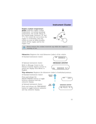
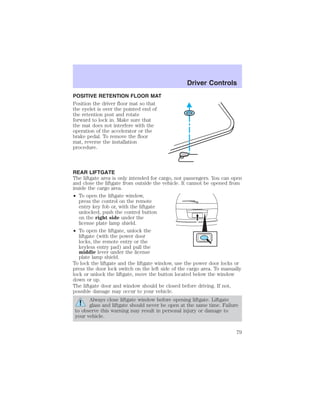
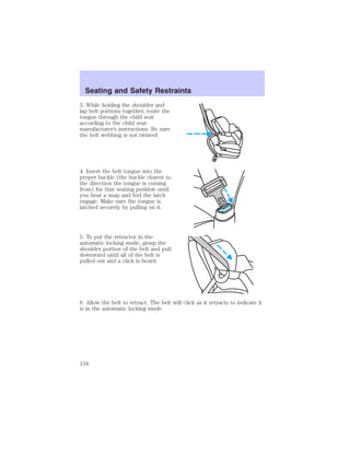
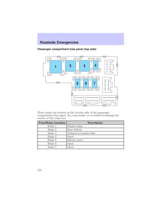
This document provides a table of contents for an owner's manual that describes various features and systems of a vehicle. The manual covers topics such as instrument clusters, entertainment systems, climate controls, lights, driver controls, locks and security, seating and safety restraints, driving, roadside emergencies, customer assistance, maintenance, and specifications. It includes warnings and instructions for proper use of the vehicle.


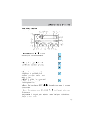


![Driver Controls
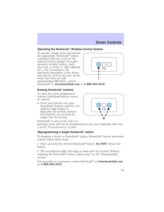
3. Locate compass sensor mounted
at base of mirror.
4. Press the button on the top of
the compass module until ZONE
appears in the instrument cluster
display.
5. Release pressure on the button and then slowly press it down again.
6. Continue to press until ZONE
appears in the instrument cluster
display, then release. The display
should show the current zone
number.
7. Press until the desired zone
number appears. The display will flash and then return to normal
operation. The zone is now updated.
Compass calibration adjustment
Perform this adjustment in an open area free from steel structures and
high voltage lines:
For optimum calibration, turn off all electrical accessories (heater/air
conditioning, wipers, etc.) and make sure all vehicle doors are shut.
1. Start the vehicle.
2. Locate compass sensor mounted at base of mirror.
3. Press the button on the top of
the compass module until ZONE
appears in the instrument cluster
display. Continue to hold down until
ZONE disappears and CAL is
displayed (approximately eight
seconds) and release.
4. Drive the vehicle slowly (less than 5 km/h [3 mph]) in circles until
CAL indicator turns off (4–5 complete circles).
5. The compass is now calibrated.
67](https://image.slidesharecdn.com/03mountaneer-140829050833-phpapp02/85/03-mountaneer-67-320.jpg)

![Driver Controls
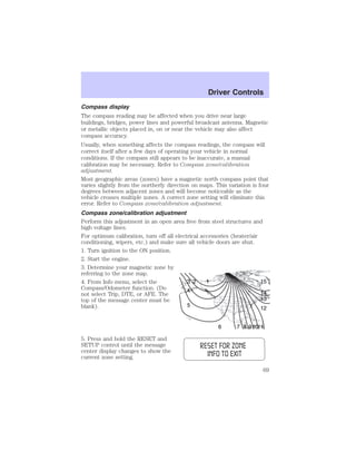
6. Release the RESET AND SETUP
control, then slowly press RESET
down again.
7. Press the SETUP control
repeatedly until the correct zone
setting for your geographic location is displayed on the message center.
To exit the zone setting mode press and release the RESET control.
8. Press the RESET control to start
the compass calibration function.
9. Slowly drive the vehicle in a
circle (less than 5 km/h [3 mph])
until the CIRCLE SLOWLY TO
CALIBRATE indicator changes to
CALIBRATION COMPLETED. This
will take up to three circles to complete calibration.
10. The compass is now calibrated.
Average fuel economy (AFE)
Select this function from the INFO
menu to display your average fuel
economy in liters/100 km or
miles/U.S. gallon.
If you calculate your average fuel
economy by dividing liters of fuel used by 100 kilometers traveled (miles
traveled by gallons used), your figure may be different than displayed for
the following reasons:
• Your vehicle was not perfectly level during fill-up
• Differences in the automatic shut-off points on the fuel pumps at
service stations
• Variations in top-off procedure from one fill-up to another
• Rounding of the displayed values to the nearest 0.1 liter (gallon)
1. Drive the vehicle at least 8 km (5 miles) with the speed control
system engaged to display a stabilized average.
2. Record the highway fuel economy for future reference.
It is important to press the RESET control after setting the speed
control to get accurate highway fuel economy readings.
70](https://image.slidesharecdn.com/03mountaneer-140829050833-phpapp02/85/03-mountaneer-70-320.jpg)


![LOW WASHER FLUID LEVEL. Indicates the washer fluid reservoir is
less than one quarter full. Check the washer fluid level. Refer to
Windshield washer fluid in the Maintenance and specifications
chapter.
DOOR AJAR. Displayed when a door or liftgate is not completely
closed.
CHANGE OIL SOON/OIL CHANGE REQUIRED. Displayed when the
engine oil life remaining is 5 percent or less. When oil life left is between
5% and 0%, the CHANGE OIL SOON message will be displayed. When oil
life left reaches 0%, the OIL CHANGE REQUIRED message will be
displayed.
An oil change is required whenever indicated by the message center.
USE ONLY RECOMMENDED ENGINE OILS.
To reset the oil monitoring system to 100% after each oil change
[approximately 8,000 km (5,000 miles) or 180 days] perform the
following:
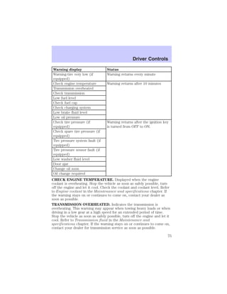
1. Press the SETUP control to
access the System Check function.
2. Press and release the RESET
control to display “OIL LIFE XX%
HOLD RESET NEW”.
3. Press and hold the RESET
control for 2 seconds to display “IF
NEW OIL HOLD RESET”.
4. Press and hold the RESET
control to display OIL LIFE SET TO
100%. Your oil life is now reset.
Driver Controls
77](https://image.slidesharecdn.com/03mountaneer-140829050833-phpapp02/85/03-mountaneer-77-320.jpg)


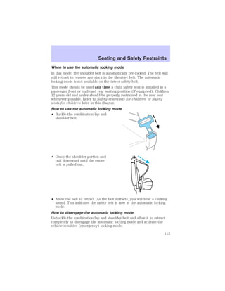


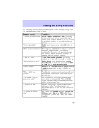


![Seating and Safety Restraints
A difficulty with the system is indicated by one or more of the following:
• The readiness light (same light as for front air bag system) will either
flash or stay lit.
• The readiness light will not illuminate immediately after ignition is
turned on.
• A series of five beeps will be heard. The tone pattern will repeat
periodically until the problem and light are repaired.
If any of these things happen, even intermittently, have the SRS serviced
at your dealership or by a qualified technician immediately. Unless
serviced, the system may not function properly in the event of a collision
or rollover event.
Disposal of air bags and air bag equipped vehicles (including
pretensioners)
See your local dealership or qualified technician. Air bags MUST BE
disposed of by qualified personnel.
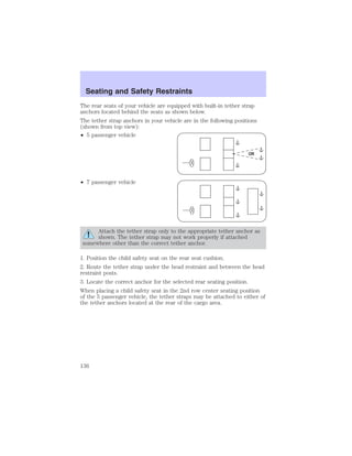
SAFETY RESTRAINTS FOR CHILDREN
See the following sections for directions on how to properly use safety
restraints for children. Also see Air bag supplemental restraint system
(SRS) in this chapter for special instructions about using air bags.
Important child restraint precautions
You are required by law to use safety restraints for children in the U.S.
and Canada. If small children (generally children who are four years old
or younger and who weigh 18 kg [40 lbs] or less) ride in your vehicle,
you must put them in safety seats made especially for children. Check
your local and state or provincial laws for specific requirements
regarding the safety of children in your vehicle. When possible, always
place children under age 12 in the rear seat of your vehicle. Accident
statistics suggest that children are safer when properly restrained in the
rear seating positions than in the front seating position.
Never let a passenger hold a child on his or her lap while the
vehicle is moving. The passenger cannot protect the child from
injury in a collision.
Always follow the instructions and warnings that come with any infant or
child restraint you might use.
128](https://image.slidesharecdn.com/03mountaneer-140829050833-phpapp02/85/03-mountaneer-128-320.jpg)


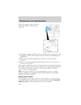

![Maintenance and Specifications
Coolant refill capacity
To find out how much fluid your vehicle’s cooling system can hold, refer
to Refill capacities in this chapter.
Fill your engine coolant reservoir as outlined in Adding engine coolant
in this chapter.
Severe climates
If you drive in extremely cold climates (less than –36° C [–34° F]), it
may be necessary to increase the coolant concentration above 50%.
Refer to the chart on the coolant container to ensure the coolant
concentration in your vehicle will provide adequate freeze protection.
Never increase the engine coolant concentration above 60%
(protection to –60°F). At a level over 60%, your engine could overheat
and become damaged.
If you drive in extremely hot climates, it is still necessary to maintain the
coolant concentration at 50/50 coolant and water. Do not allow the
coolant concentration to fall below 40% coolant. At a concentration
less than 40%, the corrosion protection to your engine and cooling
components may be compromised and permanent damage may result.
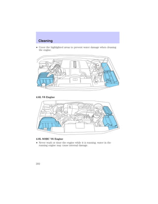
What you should know about fail-safe cooling (4.6L V8 engine only)
If the engine coolant supply is depleted, this feature allows the vehicle to
be driven temporarily before incremental component damage is incurred.
The “fail-safe” distance depends on ambient temperatures, vehicle load
and terrain.
How fail-safe cooling works
If the engine begins to overheat:
• The engine coolant temperature
gauge will move to the red (hot)
area.
• The and the symbol
will illuminate.
• The “Service Engine Soon”
indicator light will illuminate.
If the engine reaches a preset over-temperature condition, the engine
will automatically switch to alternating cylinder operation. Each disabled
cylinder acts as an air pump and cools the engine.
223](https://image.slidesharecdn.com/03mountaneer-140829050833-phpapp02/85/03-mountaneer-223-320.jpg)


![Maintenance and Specifications
3. After at least three to five tank fill-ups, fill the fuel tank and record
the current odometer reading.
4. Subtract your initial odometer reading from the current odometer
reading.
5. Follow one of the simple calculations in order to determine fuel
economy:
Calculation 1: Multiply liters used by 100, then divide by total
kilometers traveled.
Calculation 2: Divide total miles traveled by total gallons used.
Keep a record for at least one month and record the type of driving (city
or highway). This will provide an accurate estimate of the vehicle’s fuel
economy under current driving conditions. Additionally, keeping records
during summer and winter will show how temperature impacts fuel
economy. In general, lower temperatures give lower fuel economy.
Driving style — good driving and fuel economy habits
Give consideration to the lists that follow and you may be able to change
a number of variables and improve your fuel economy.
Habits
• Smooth, moderate operation can yield up to 10% savings in fuel.
• Steady speeds without stopping will usually give the best fuel
economy.
• Idling for long periods of time (greater than one minute) may waste
fuel.
• Anticipate stopping; slowing down may eliminate the need to stop.
• Sudden or hard accelerations may reduce fuel economy.
• Slow down gradually.
• Driving at reasonable speeds (traveling at 88 km/h [55 mph] uses 15%
less fuel than traveling at 105 km/h [65 mph]).
• Revving the engine before turning it off may reduce fuel economy.
• Using the air conditioner or defroster may reduce fuel economy.
• You may want to turn off the speed control in hilly terrain if
unnecessary shifting between third and fourth gear occurs.
Unnecessary shifting of this type could result in reduced fuel
economy.
• Warming up a vehicle on cold mornings is not required and may
reduce fuel economy.
232](https://image.slidesharecdn.com/03mountaneer-140829050833-phpapp02/85/03-mountaneer-232-320.jpg)
![Maintenance and Specifications
• Resting your foot on the brake pedal while driving may reduce fuel
economy.
• Combine errands and minimize stop-and-go driving.
Maintenance
• Keep tires properly inflated and use only recommended size.
• Operating a vehicle with the wheels out of alignment will reduce fuel
economy.
• Use recommended engine oil. Refer to Lubricant specifications in
this chapter.
• Perform all regularly scheduled maintenance items. Follow the
recommended maintenance schedule and owner maintenance checks
found in your vehicle scheduled maintenance guide.
Conditions
• Heavily loading a vehicle or towing a trailer may reduce fuel economy
at any speed.
• Carrying unnecessary weight may reduce fuel economy (approximately
0.4 km/L [1 mpg] is lost for every 180 kg [400 lb] of weight carried).
• Adding certain accessories to your vehicle (for example bug
deflectors, rollbars/light bars, running boards, ski/luggage racks) may
reduce fuel economy.
• Fuel economy may decrease with lower temperatures during the first
12–16 km (8–10 miles) of driving.
• Driving on flat terrain offers improved fuel economy as compared to
driving on hilly terrain.
• Transmissions give their best fuel economy when operated in the top
cruise gear and with steady pressure on the gas pedal.
• Four-wheel-drive operation (if equipped) is less fuel efficient than
two-wheel-drive operation.
• Close windows for high speed driving.
Flex fuel (E-85) cruising range
Because E-85 fuel contains less energy per gallon than gasoline, you will
experience an increase in fuel consumption. You can expect your Miles
Per Gallon (MPG) and your driving range to decrease by about 30%
compared to gasoline operation.
EPA window sticker
Every new vehicle should have the EPA window sticker. Contact your
dealer if the window sticker is not supplied with your vehicle. The EPA
window sticker should be your guide for the fuel economy comparisons
with other vehicles.
233](https://image.slidesharecdn.com/03mountaneer-140829050833-phpapp02/85/03-mountaneer-233-320.jpg)


![• The Federal Communications Commission (FCC) and Canadian Radio
Telecommunications Commission (CRTC) regulate the use of mobile
communications systems - such as two-way radios, telephones and
theft alarms - that are equipped with radio transmitters. Any such
equipment installed in your vehicle should comply with FCC or CRTC
regulations and should be installed only by a qualified service
technician.
• Mobile communications systems may harm the operation of your
vehicle, particularly if they are not properly designed for automotive
use or are not properly installed. When operated, such systems may
cause the engine to stumble or stall or cause the transmission to be
damaged or operate improperly. In addition, such systems may be
damaged or their performance may be affected by operating your
vehicle. (Citizens band [CB] transceivers, garage door openers and
other transmitters with outputs of five watts or less will not ordinarily
affect your vehicle’s operation.)
• Ford cannot assume responsibility for any adverse effects or damage
that may result from the use of such equipment.
Accessories
255](https://image.slidesharecdn.com/03mountaneer-140829050833-phpapp02/85/03-mountaneer-255-320.jpg)