This document is a table of contents for an owner's manual that covers various vehicle systems and components. The table of contents lists sections on instrument clusters, entertainment systems, climate controls, lights, driver controls, safety restraints, driving instructions, roadside emergencies, customer assistance, maintenance, and specifications. It also includes brief introductions to warnings, congratulations on the new vehicle, breaking-in procedures, special notices, and warning symbol glossaries.


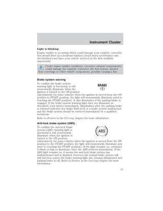


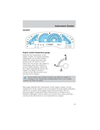


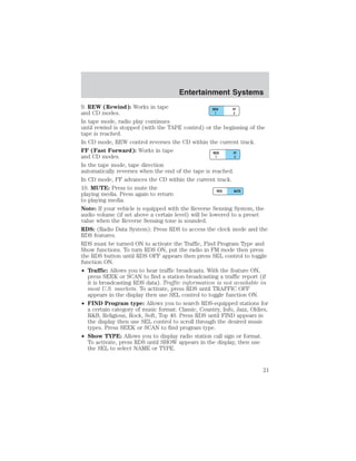


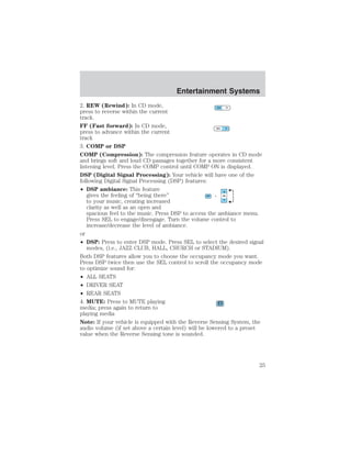


![Driver Controls
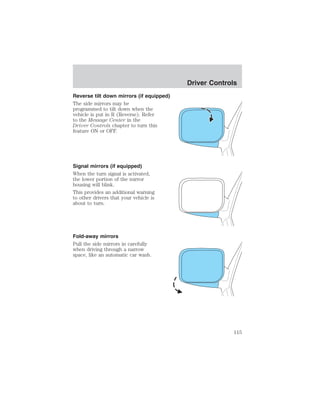
Compass calibration adjustment
Perform this adjustment in an open area free from steel structures and
high voltage lines. For optimum calibration, turn off all electrical
accessories (heater/air conditioning, wipers, etc.) and make sure all
vehicle doors are shut.
1. Start the vehicle.
2. To enter the compass calibration
mode, press and hold the
TRIP/RESET button for greater than
eight seconds. The display will then
show CAL in the display window.
3. Drive the vehicle slowly (less than 5 km/h [3 mph]) in circles until
CAL indicator turns off. As many as 5 complete circles may be required.
4. The compass is now calibrated.
MESSAGE CENTER (IF EQUIPPED)
With the ignition in the ON position,
the message center, located on your
instrument cluster, displays
important vehicle information
through a constant monitor of
vehicle systems. You may select
display features on the message center for a display of status preceded
by a brief indicator chime. The system will also notify you of potential
vehicle problems with a display of system warnings followed by a long
indicator chime.
Selectable features
Reset
Press this control to select and reset
functions shown in the INFO menu
and SETUP menu.
127](https://image.slidesharecdn.com/03expedition-140829050756-phpapp02/85/03-expedition-127-320.jpg)

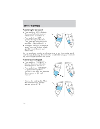
![Compass zone/calibration adjustment
1. Determine your magnetic zone by
referring to the zone map.
2. Turn ignition to the ON position.
3. Start the engine.
4. From Info menu, select the
Compass/Odometer function. (Do
not select Trip, DTE, or AFE. The
top of the message center must be
blank).
Driver Controls
3 2 1
4
5
15
14
13
12
6 7 8 91011
5. Press and hold the SETUP and
RESET controls until the message
center display changes to show the
current zone setting (XX).
6. Press the SETUP control
repeatedly until the correct zone setting for your geographic location is
displayed on the message center. The range of zone values are from 01
to 15 and “wraps” back to 01.
7. To exit the zone setting mode,
and to “lock in” your change, press
and release the RESET control.
Perform compass calibration in an open area free from steel structures
and high voltage lines. For optimum calibration, turn off all electrical
accessories (heater/air conditioning, wipers, etc.) and make sure all
vehicle doors are shut.
8. Press the RESET control to start
the compass calibration function.
9. Slowly drive the vehicle in a
circle (less than 5 km/h [3 mph])
until the CIRCLE SLOWLY TO
CALIBRATE display changes to CALIBRATION COMPLETED. It will take
up to five circles to complete calibration.
129](https://image.slidesharecdn.com/03expedition-140829050756-phpapp02/85/03-expedition-129-320.jpg)


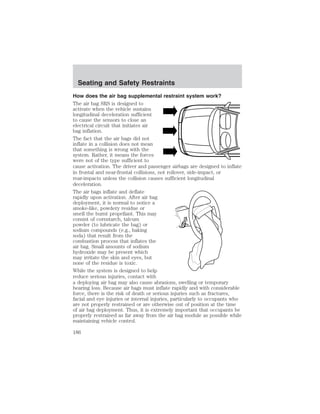

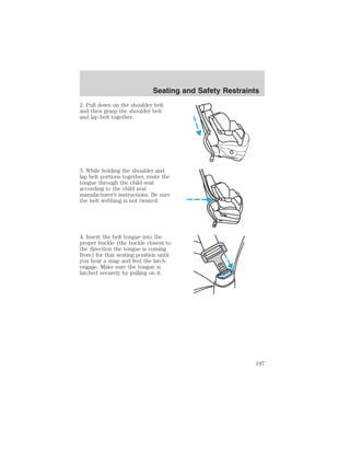
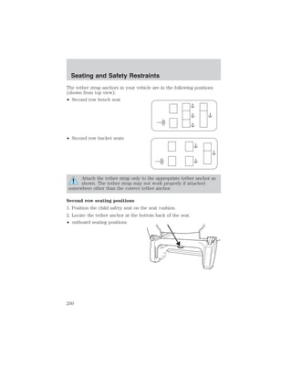
![Seating and Safety Restraints
Determining if the system is operational
The SRS uses a readiness light in the instrument cluster or a tone to
indicate the condition of the system. Refer to the Air bag readiness
section in the Instrument Cluster chapter. Routine maintenance of the
air bag is not required.
Any difficulty with the system is indicated by one or more of the
following:
• The readiness light (same light as for front air bag system) will either
flash or stay lit.
• The readiness light will not illuminate immediately after ignition is
turned on.
• A series of five beeps will be heard. The tone pattern will repeat
periodically until the problem and light are repaired.
If any of these things happen, even intermittently, have the SRS serviced
at your dealership or by a qualified technician immediately. Unless
serviced, the system may not function properly in the event of a collision
or rollover event.
Disposal of air bags and air bag equipped vehicles (including
pretensioners)
See your local dealership or qualified technician. Air bags MUST BE
disposed of by qualified personnel.
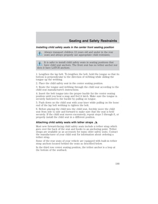
SAFETY RESTRAINTS FOR CHILDREN
See the following sections for directions on how to properly use safety
restraints for children. Also see Air bag supplemental restraint system
(SRS) in this chapter for special instructions about using air bags.
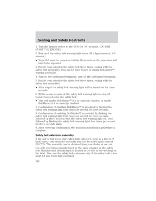
Important child restraint precautions
You are required by law to use safety restraints for children in the U.S.
and Canada. If small children (generally children who are four years old
or younger and who weigh 18 kg [40 lbs] or less) ride in your vehicle,
you must put them in safety seats made especially for children. Check
your local and state or provincial laws for specific requirements
regarding the safety of children in your vehicle. When possible, always
place children under age 12 in the rear seat of your vehicle. Accident
statistics suggest that children are safer when properly restrained in the
rear seating positions than in the front seating position.
191](https://image.slidesharecdn.com/03expedition-140829050756-phpapp02/85/03-expedition-191-320.jpg)


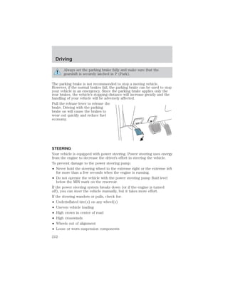
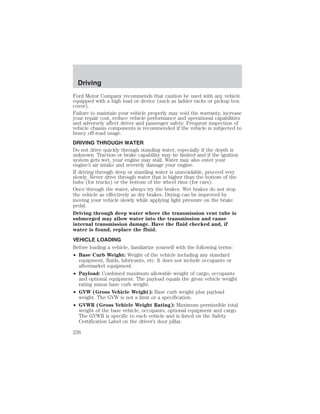
![Driving
Speed sensitive steering
Your vehicle is equipped with engine speed sensitive steering. At higher
engine speeds associated with high vehicle speed, the steering assist will
decrease to improve steering feel.
If the amount of effort required to steer your vehicle changes while
maintaining a constant engine speed, have the power steering system
checked by your dealer or a qualified service technician.
AIR SUSPENSION SYSTEM (IF EQUIPPED)
The air suspension system is designed to improve ride comfort, vehicle
handling and general vehicle performance by adjusting the vehicle’s ride
height according to vehicle speed, weight added to or removed from the
vehicle and four-wheel drive (if equipped) operation. Normal vehicle
operation does not require any action by the driver.
When you enter the vehicle and the ignition is off, the air suspension will
have automatically lowered the vehicle to its lowest height to provide
easier entry. When a door or the liftgate is opened, the system
memorizes and maintains that height until either all doors are closed or
the vehicle’s speed exceeds 24 km/h (15 mph). The air suspension
system will then raise the vehicle’s height to its normal position when the
ignition is turned on, all doors are closed and the transmission is shifted
from P (Park).
When the vehicle is in motion, the air suspension will adjust the vehicle
ride height to normal operating position to maximize your ride comfort.
If your vehicle is equipped with four-wheel drive and you shift into 4WD
LOW, the air suspension will not move to it’s lowest position; instead, the
ride height is raised above the normal ride height position (at speeds
below 40 km/h [25 mph]) to improve ground clearance.
If a load is added to, or removed from the vehicle, the load leveling
feature of the air suspension system will adjust the suspension to keep
the vehicle at a constant level.
When exiting the vehicle, the air suspension will automatically lower the
vehicle to its lowest height to provide easier exit. You may hear a buzz or
click from the air suspension system when the ignition is turned off. The
air suspension system will stay active for 40 minutes after the ignition is
turned off to accommodate any load changes. (The air compressor may
run when the vehicle is off; this is normal.)
213](https://image.slidesharecdn.com/03expedition-140829050756-phpapp02/85/03-expedition-213-320.jpg)


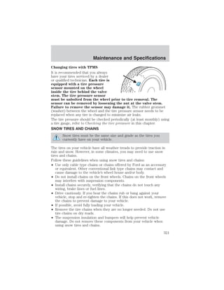
![Maintenance and Specifications
After any coolant has been added, check the coolant concentration, refer
to Checking Engine Coolant section. If the concentration is not 50/50
(protection to –34° F/–36° C), drain some coolant and adjust the
concentration. It may take several drains and additions to obtain a 50/50
coolant concentration.
Whenever coolant has been added, the coolant level in the coolant
reservoir should be checked the next few times you drive the vehicle. If
necessary, add enough 50/50 concentration of engine coolant and
distilled water to bring the liquid level to the proper level.
If you have to add more than 1.0 liter (1.0 quart) of engine coolant per
month, have your dealer check the engine cooling system. Your cooling
system may have a leak. Operating an engine with a low level of coolant
can result in engine overheating and possible engine damage.
Recycled engine coolant
Ford Motor Company does NOT recommend the use of recycled engine
coolant in vehicles originally equipped with Motorcraft Premium Gold
Engine Coolant since a Ford-approved recycling process is not yet
available.
Used engine coolant should be disposed of in an appropriate
manner. Follow your community’s regulations and standards for recycling
and disposing of automotive fluids.
Coolant refill capacity
To find out how much fluid your vehicle’s cooling system can hold, refer
to Refill capacities in this chapter.
Fill your engine coolant reservoir as outlined in Adding engine coolant
in this chapter.
Severe climates
If you drive in extremely cold climates (less than –36° C [–34° F]):
• It may be necessary to increase the coolant concentration
above 50%.
• NEVER increase the coolant concentration above 60%.
• Increased engine coolant concentrations above 60% will
decrease the overheat protection characteristics of the engine
coolant and may cause engine damage.
• Refer to the chart on the coolant container to ensure the
coolant concentration in your vehicle will provide adequate
freeze protection at the temperatures in which you drive in the
winter months.
300](https://image.slidesharecdn.com/03expedition-140829050756-phpapp02/85/03-expedition-300-320.jpg)


![Maintenance and Specifications
• Idling for long periods of time (greater than one minute) may waste
fuel.
• Anticipate stopping; slowing down may eliminate the need to stop.
• Sudden or hard accelerations may reduce fuel economy.
• Slow down gradually.
• Driving at reasonable speeds (traveling at 88 km/h [55 mph] uses 15%
less fuel than traveling at 105 km/h [65 mph]).
• Revving the engine before turning it off may reduce fuel economy.
• Using the air conditioner or defroster may reduce fuel economy.
• You may want to turn off the speed control in hilly terrain if
unnecessary shifting between third and fourth gear occurs.
Unnecessary shifting of this type could result in reduced fuel
economy.
• Warming up a vehicle on cold mornings is not required and may
reduce fuel economy.
• Resting your foot on the brake pedal while driving may reduce fuel
economy.
• Combine errands and minimize stop-and-go driving.
Maintenance
• Keep tires properly inflated and use only recommended size.
• Operating a vehicle with the wheels out of alignment will reduce fuel
economy.
• Use recommended engine oil. Refer to Lubricant specifications in
this chapter.
• Perform all regularly scheduled maintenance items. Follow the
recommended maintenance schedule and owner maintenance checks
found in your vehicle scheduled maintenance guide.
Conditions
• Heavily loading a vehicle or towing a trailer may reduce fuel economy
at any speed.
• Carrying unnecessary weight may reduce fuel economy (as much as
0.4 km/L [1 mpg] is lost for every 180 kg [400 lb] of weight carried).
• Adding certain accessories to your vehicle (for example bug
deflectors, rollbars/light bars, running boards, ski/luggage racks) may
reduce fuel economy.
309](https://image.slidesharecdn.com/03expedition-140829050756-phpapp02/85/03-expedition-309-320.jpg)


![Maintenance and Specifications
BRAKE FLUID RESERVOIR
The fluid level will drop slowly as
the brakes wear, and will rise when
the brake components are replaced.
Fluid levels between the “MIN” and
MAX
“MAX” lines are within the normal
operating range, there is no need to
MIN
add fluid. If the fluid levels are
outside of the normal operating range, the performance of your brake
system could be compromised, seek service from your dealer
immediately.
TRANSMISSION FLUID
Checking automatic transmission fluid
Refer to your scheduled maintenance guide for scheduled intervals for
fluid checks and changes. Your transmission does not consume fluid.
However, the fluid level should be checked if the transmission is not
working properly, i.e., if the transmission slips or shifts slowly or if you
notice some sign of fluid leakage.
Automatic transmission fluid expands when warmed. To obtain an
accurate fluid check, drive the vehicle until it is at normal operating
temperature (approximately 30 km [20 miles]). If your vehicle has been
operated for an extended period at high speeds, in city traffic during hot
weather or pulling a trailer, the vehicle should be turned off for about 30
minutes to allow fluid to cool before checking.
1. Drive the vehicle 30 km (20 miles) or until it reaches normal operating
temperature.
2. Park the vehicle on a level surface and engage the parking brake.
3. With the parking brake engaged and your foot on the brake pedal,
start the engine and move the gearshift lever through all of the gear
ranges. Allow sufficient time for each gear to engage.
4. Latch the gearshift lever in P (Park) and leave the engine running.
5. Remove the dipstick, wiping it clean with a clean, dry lint free rag. If
necessary, refer to Identifying components in the engine compartment
in this chapter for the location of the dipstick.
6. Install the dipstick making sure it is fully seated in the filler tube.
7. Remove the dipstick and inspect the fluid level. The fluid should be in
the designated area for normal operating temperature or ambient
temperature.
313](https://image.slidesharecdn.com/03expedition-140829050756-phpapp02/85/03-expedition-313-320.jpg)
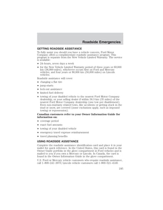
![Maintenance and Specifications
Low fluid level
Do not drive the vehicle if the fluid
level is at the bottom of the dipstick
and the ambient temperature is
ADD COLD HOT DO NOT ADD
above 10°C (50°F).
Correct fluid level
The transmission fluid should be checked at normal operating
temperature 66°C-77°C (150°F-170°F) on a level surface. The normal
operating temperature can be reached after approximately 30 km (20
miles) of driving.
You can check the fluid without driving if the ambient temperature is
above 10°C (50°F). However, if fluid is added at this time, an overfill
condition could result when the vehicle reaches normal operating
temperature.
The transmission fluid should be in
this range if at normal operating
temperature (66°C-77°C
ADD COLD HOT DO NOT ADD
[150°F-170°F]).
The transmission fluid should be in
this range if at ambient temperature
(10°C-35°C [50°F-95°F]).
ADD COLD HOT DO NOT ADD
High fluid level
Fluid levels above the safe range
may result in transmission failure.
An overfill condition of transmission
ADD COLD HOT DO NOT ADD
fluid may cause shift and/or
engagement concerns and/or possible damage.
High fluid levels can be caused by an overheating condition.
Adjusting automatic transmission fluid levels
Before adding any fluid, make sure the correct type is used. The type of
fluid used is normally indicated on the dipstick and also in the
Lubricant specifications section in this chapter.
Use of a non-approved automatic transmission fluid may cause
internal transmission component damage.
If necessary, add fluid in 250 mL (1/2 pint) increments through the filler
tube until the level is correct.
314](https://image.slidesharecdn.com/03expedition-140829050756-phpapp02/85/03-expedition-314-320.jpg)


![Accessories
• The Federal Communications Commission (FCC) and Canadian Radio
Telecommunications Commission (CRTC) regulate the use of mobile
communications systems - such as two-way radios, telephones and
theft alarms - that are equipped with radio transmitters. Any such
equipment installed in your vehicle should comply with FCC or CRTC
regulations and should be installed only by a qualified service
technician.
• Mobile communications systems may harm the operation of your
vehicle, particularly if they are not properly designed for automotive
use or are not properly installed. When operated, such systems may
cause the engine to stumble or stall or cause the transmission to be
damaged or operate improperly. In addition, such systems may be
damaged or their performance may be affected by operating your
vehicle. (Citizens band [CB] transceivers, garage door openers and
other transmitters with outputs of five watts or less will not ordinarily
affect your vehicle’s operation.)
• Ford cannot assume responsibility for any adverse effects or damage
that may result from the use of such equipment.
• Do not install equipment which modifies the vehicles suspension or
steering. Such modifications can cause adverse effects to the
AdvanceTrac system.
• Do not install a loudspeaker in the area of the front floor console or
under the front driver or passenger seats. The speaker vibrations can
adversely effect the AdvanceTrac sensors.
334](https://image.slidesharecdn.com/03expedition-140829050756-phpapp02/85/03-expedition-334-320.jpg)