
Recommended
More Related Content
What's hot
What's hot (7)
Similar to 293431 100002 eng
Similar to 293431 100002 eng (20)
Recently uploaded
Recently uploaded (20)
293431 100002 eng
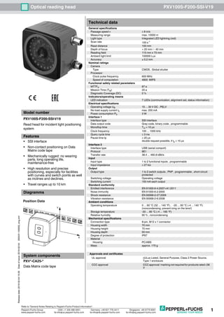
- 1. 1 Releasedate:2019-02-0415:39Dateofissue:2019-02-04293431-100002_eng.xml Optical reading head PXV100S-F200-SSI-V19 Germany: +49 621 776 4411Pepperl+Fuchs Group Refer to “General Notes Relating to Pepperl+Fuchs Product Information”. USA: +1 330 486 0001 Singapore: +65 6779 9091 www.pepperl-fuchs.com fa-info@us.pepperl-fuchs.com fa-info@sg.pepperl-fuchs.comfa-info@de.pepperl-fuchs.com Technical data General specifications Passage speed v ≤ 8 m/s Measuring range max. 10000 m Light type Integrated LED lightning (red) Scan rate 100 s-1 Read distance 100 mm Depth of focus + 20 mm / - 40 mm Reading field 115 mm x 73 mm Ambient light limit 100000 Lux Accuracy ± 0.2 mm Nominal ratings Camera Type CMOS , Global shutter Processor Clock pulse frequency 600 MHz Speed of computation 4800 MIPS Functional safety related parameters MTTFd 87 a Mission Time (TM) 20 a Diagnostic Coverage (DC) 0 % Indicators/operating means LED indication 7 LEDs (communication, alignment aid, status information) Electrical specifications Operating voltage UB 15 ... 30 V DC , PELV No-load supply current I0 max. 200 mA Power consumption P0 3 W Interface 1 Interface type SSI interface Data output code Gray code, binary code , programmable Monoflop time Tm = 10 µs Clock frequency 100 ... 1000 kHz Query cycle time ≥ 3 ms Pause time tp ≥ 20 µs double request possible, if tp ≤ 10 µs Interface 2 Interface type USB (serial comport) Protocol 8E1 Transfer rate 38.4 ... 460.8 kBit/s Input Input type 1 to 2 functional inputs , programmable Input impedance ≥ 27 kΩ Output Output type 1 to 2 switch outputs , PNP , programmable , short-circuit protected Switching voltage Operating voltage Switching current 150 mA each output Standard conformity Emitted interference EN 61000-6-4:2007+A1:2011 Noise immunity EN 61000-6-2:2005 Shock resistance EN 60068-2-27:2009 Vibration resistance EN 60068-2-6:2008 Ambient conditions Operating temperature 0 ... 60 °C (32 ... 140 °F) , -20 ... 60 °C (-4 ... 140 °F) (noncondensing; prevent icing on the lens!) Storage temperature -20 ... 85 °C (-4 ... 185 °F) Relative humidity 90 % , noncondensing Mechanical specifications Connection type 8-pin, M12 x 1 connector Housing width 70 mm Housing height 70 mm Housing depth 50 mm Degree of protection IP67 Material Housing PC/ABS Mass approx. 170 g Approvals and certificates UL approval cULus Listed, General Purpose, Class 2 Power Source, Type 1 enclosure CCC approval CCC approval / marking not required for products rated ≤36 V Model number PXV100S-F200-SSI-V19 Read head for incident light positioning system Features • SSI interface • Non-contact positioning on Data Matrix code tape • Mechanically rugged: no wearing parts, long operating life, maintenance-free • High resolution and precise positioning, especially for facilities with curves and switch points as well as inclines and declines. • Travel ranges up to 10 km Diagramms System components PXV*-CA25-* Data Matrix code tape 000 009.0 m PXV-AA25 www.pepperl-fuchs.com Y X Position Data
- 2. Releasedate:2019-02-0415:39Dateofissue:2019-02-04293431-100002_eng.xml 2 PXV100S-F200-SSI-V19Optical reading head Germany: +49 621 776 4411Pepperl+Fuchs Group Refer to “General Notes Relating to Pepperl+Fuchs Product Information”. USA: +1 330 486 0001 Singapore: +65 6779 9091 www.pepperl-fuchs.com fa-info@us.pepperl-fuchs.com fa-info@sg.pepperl-fuchs.comfa-info@de.pepperl-fuchs.com Additional information Accessories V19-G-ABG-PG9 Female connector, M12, 8-pin, shielded, field attachable V19-G-ABG-PG9-FE Female connector, M12, 8-pin, shielded, field attachable PCV-KBL-V19-STR-USB USB cable unit with power supply PCV-SC12 Grounding clip for PCV system PCV-LM25 Marker head for 25 mm code tape PCV-MB1 Mounting bracket for PCV* read head PCV-AG100 Alignment guide for PCV100-* read head Vision Configurator Operating software for camera-based sensors COMSERVICE SSIDATA/CONFIG OUT2/ADJY OUT3/ADJZ PWR/ADJ ERR/NOCODE INTERNAL DIAGNOSTIC ADJUST CONFIG 1 2 LED 1 2 3 4 5 6 7 General The reader forms part of the positioning system in the Pepperl+Fuchs incident light process. The reader's features include a camera module and an integrated illumination unit, enabling it to detect position markers printed onto an adhesive code tape in the form of Data Matrix codes. Generally speaking, the code tape is mounted stationary on a fixed part of the plant (e.g., elevator shaft, overhead conveyor mounting rails) and the reader is mounted parallel on the moving "vehicle" (e.g., elevator car, overhead conveyor chassis). Mounting and Commissioning Mount the reader such that the optical surface of the device captures the optimal reading distance to the code tape (see "Technical Data"). The stability of the mounting and the manner in which the vehicle is guided ensure that the Dimensions Electrical connection Pinout 712 3 45 68 7 1 2 3 45 6 8 70 80 38.5 70 14.5 1 2 22 51 ø25 12 M12x1 9 4xM640 1 2 3 4 5 6 7 8 OUT 2 / IN 2 + UB Data + Data - CLK+ CLK- GND OUT 3 / IN 3 1 4 6 7 8 53 2
- 3. 3 Releasedate:2019-02-0415:39Dateofissue:2019-02-04293431-100002_eng.xml Optical reading head PXV100S-F200-SSI-V19 Germany: +49 621 776 4411Pepperl+Fuchs Group Refer to “General Notes Relating to Pepperl+Fuchs Product Information”. USA: +1 330 486 0001 Singapore: +65 6779 9091 www.pepperl-fuchs.com fa-info@us.pepperl-fuchs.com fa-info@sg.pepperl-fuchs.comfa-info@de.pepperl-fuchs.com reader is not operated outside of its depth of focus range. All readers can be adapted to optimally meet specific requirements through parameterization. Indicators and Operating Elements The reader is equipped with seven indicator LEDs for carrying out visual function checks and quick diagnostics. The reader is equipped with two buttons at the back for activating the alignment aid and parameterization mode. LEDs Data Log Position data encoded in XP0 ... XP21 (MSB first) Meaning of status bits Error codes External Parameterization To parameterize the device externally, the parameterization code is required in the form of a Data Matrix contai- ning the desired reader parameters. Data Matrix code cards detailing the step-by-step process for externally pa- rameterizing the device are printed in the operating instructions for the reader. The reader can be parameterized only within ten minutes of being switched on. If a key is pressed after ten minutes of the device being switched on, a visual signal is given by the LEDs (LED1, yellow/LED2, red/LED3, yellow/LED4, yellow/LED5, yellow, flashing for two seconds). • The switchover from normal mode to parameterization mode is made by pressing button 2 on the back of the reader. To switch the device over, button 2 must be pressed and held for more than two seconds. LED3 then flashes. Note: Parameterization mode is exited automatically if the device is inactive for one minute. In this case, the reader reverts to normal mode and operates without the settings having been changed. • Place the parameterization code in the field of vision of the camera module. After the parameterization code is detected, the green LED2 lights up for one second. In the event of an invalid parameterization code, LED2 lights up red for two seconds. • Briefly pressing button 2 will end parameterization mode and the changed parameters are saved in the non- volatile memory of the reader. Alignment Aid for the Y and Z Coordinates The activation of the alignment aid is possible only within ten minutes of switching on the reader. The switchover from normal mode to "Alignment aid" mode is performed via button 1 on the back of the reader. • Press the button 1 for longer than two seconds. LED2 flashes green for a recognized code tape. LED2 flash- es red for an unrecognized code tape. • Z coordinate: If the distance of the camera to the code tape is too small, the yellow LED5 lights up. If the distance is too great, the yellow LED5 goes out. Within the target range, the yellow LED5 and the green LED2 flash synchronously. • Y coordinate: If the optical axis of the camera is too low relative to the middle of the code tape, the yellow LED4 lights up. If the optical axis is too high, the yellow LED4 goes out. Within the target range, the yellow LED4 and the green LED2 flash synchronously. • Briefly pressing button 1 ends the alignment aid, and the reader switches to normal mode. LED Color Label Meaning 1 Yellow COM Communication active to USB interface 2 Green/red PWR/ADJ ERR/NO CODE Code detected/not detected, error 3 Yellow SSI DATA/CONFIG Data flow to SSI interface/configuration 4 Yellow OUT2/ADJ Y Output 2, alignment aid Y 5 Yellow OUT3/ADJ Z Output 3, alignment aid Z 6, 7 Red/green/yel- low INTERNAL DIAGNOSTIC Internal diagnostics 1 2 3 4 5 6 7 8 9 10 11 12 13 14 15 16 Data XP21 XP20 XP19 XP18 XP17 XP16 XP15 XP14 XP13 XP12 XP11 XP10 XP9 XP8 XP7 XP6 MSB 17 18 19 20 21 22 23 24 25 Data XP5 XP4 XP3 XP2 XP1 XP0 Out Wrn Err MSB LSB Status bits Out Err Wrn Meaning X X 1 Reserved X 1 X Error, error code in XP0 ... XP21 1 X X No position codes in the reading window (XP0 ... XP21 = 0) Error code Meaning 1 Reader aligned incorrectly (rotated 180°) 2 Position error: Position codes in the reading window are not unique >1000 Internal fault