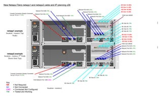
This document provides a network and cabling plan for two new NetApp filers named netapp1 and netapp2. It includes a logical view of how the filers will connect to each other and to network switches via Ethernet ports and virtual interfaces using links such as LACP. Physical locations and IP addressing information are also documented.
S-functions Paper Presentation: Switching Amplifier Design With S-functions
NetApp Design Example
1. New Netapp Filers netapp1 and netapp2 cable and IP planning v06 BE Disk 1D (NR))
BE Disk 1C (NR)
Network Port E4D (TW) BE Disk 1B (NR)
Network Port E0B (TW)
Network Port E4C (TW) BE Disk 1A (NR)
Console Connection Already Connected
Network Port E0A (TW) Network Port E4B (TW)
legcygd-106 port 17 (TW) PAM Card 256GB
RLM Network Port E0M (TW)
Network Port E4A (TW)
X2054A
A B C D
PORTS
PORT D PORT C PORT B PORT A BE Disk 0A (TW)
BE Disk 0B (TW)
BE Disk 0C (TW)
netapp1.example BE Disk 0D (TW)
location - roomxx Top
X1936A
X1006A
BE Disk 1D (NR)
Node)
e0a e0b
BE Disk 1C (NR)
0a 0b 0c 0d
BE Disk 1B (NR)
BE Disk 1A (NR)
PAM Card 256GB
Network Port E4D (TW)
X2054A
A B C D
PORTS
PORT D PORT C PORT B PORT A
Network Port E4C (TW)
Network Port E4B (TW)
netapp2.example Network Port E4A (TW)
location - roomxx 2nd Node
X1936A
Down from Top)
X1006A
e0a e0b
0a 0b 0c 0d
Console Connection Already Connected Network Port E0A (TW)
legcygd-106 port 19 (TW) BE Disk 0D (TW)
Network Port E0B (TW)
BE Disk 0C (TW)
RLM Network Port E0M (CNC)
BE Disk 0B (TW)
Key BE Disk 0A (TW)
NR = Not Required
NC = Not Connected
location - roomxx)
CNC = Connected Not Configured
TW = Tested and Working