
Recommended
More Related Content
Similar to Mixer Ingredient Feed
Similar to Mixer Ingredient Feed (20)
Recently uploaded
Recently uploaded (20)
Mixer Ingredient Feed
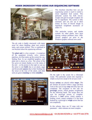
- 1. MIXER INGREDIENT FEED USING OUR SEQUENCING SOFTWARE This brochure describes how our plc sequencing system is used to control a mixer ingredient feed system. This particular system has both loss-in- weight and gain-in-weight weighers for the 12 ingredients. The system is fully automatic and can mix up to three tonnes an hour of biscuit dough to ingredient weighment accuracies of under 1%. This particular system, and similar systems for other plants, have been running without problems since 1984. (Screen graphics are prior to the Windows graphic software now used). The plc code is highly structured, with major areas for alarm handling, plant unit control, tasks, and system utilities. This is explained in our brochure about the sequencing software. The plant unit is a key concept – it comprises all the equipment (vessels, valve, motors, pipelines, etc) that makes up the system for, say, feeding flour. In our simplified graphics, each plant unit is shown as a box. The colour of the box gives an instant display as to the status of the unit – on the picture to the right we can see the mixer is red (hold) due to an alarm, sugar and fat are pink (pause) due to their feeding into the mixer at the time of the alarm, and other units are green (running) or white (standby). On the right is the screen for a (fictional) recipe. This particular system also required a simple acid premix recipe to be set up as well. Recipe actions are placed within stages. The plc initiates all actions within a stage and then waits at the end of stage step until they have all completed. The exception to this rule are preweigh actions, which prepare weighments for the following batch. The recipe does not wait for preweigh actions to complete. (However, a feed action, which empties a holding vessel, cannot complete if it has been booked by a preweigh or weigh action that has not completed). In this scheme, there are 32 steps with one parameter – other schemes are more complex. www.etprocessdesign.co.uk +44 (0)1404 823650 or +44 0775 444 2578
- 2. Once a recipe has been downloaded to the plc and started, the first scan of the recipe kicks off preweigh tasks only. The next scan then kicks off all tasks within the first stage. This is the point that the system status screen on the right shows, with active steps shown in green. Two of the three preweigh tasks have completed and are shown, with achieved weights, in white. The menus can be touch screen buttons or, in this case, function buttons. The first button at the top right allows any target weight to be altered in the current recipe. The bottom line shows the current alarm. The alarm screen shows which alarms are active and in hold (red), which are dead and awaiting reset (yellow) and dead, reset historic alarms (white). Alarms must be individually reset. Individually resetting alarms ensures that only selected plant units are restarted, and thus other, unexpected faults (such as transitory alarms – eg fat tank overfull) can be investigated before being restarted. Some faults on investigation will be seen to be due to switches going out of adjustment and causing an alarm, even though the plant is working correctly. In this instance, maintenance can decide to inhibit the alarm via a password protected screen. This will prevent the alarm from being triggered and give maintenance time to schedule the repair, whilst permitting the plant to continue to work normally. Alarm inhibits are automatically reset every day at a specific time. Safety alarms cannot be inhibited, of course. www.etprocessdesign.co.uk +44 (0)1404 823650 or +44 0775 444 2578
- 3. There are instances where the graphics terminal may be remote from the plc controlling the plant, or where the atmosphere restricts the opening of the cabinet. For these plants we provide an additional screen that shows the state of the plc’s inputs and outputs (I/O). I/O that operate for a very short time cannot be displayed, but the system is very useful for verifying that the program is actually driving an output, or that another section of plant is powering an input. The more advanced systems are fitted with simulation software. This permits the plant to be used for training purposes outside production periods. A supervisor keyswitch is used to put the plant into simulation mode when it has shutdown. Simple simulation consists of downloading a recipe and showing new staff how the plant operates in real life. The plc drives the plant as per normal, except that all outputs are masked off, thus preventing drives from operating. Inputs are simulated, including the weighment of ingredients and the discharge of vessels. More complex simulation involves downloading a list of simulated alarms. These will occur at the correct point in the operation and operators can be trained in the actions to take. An engineering version also creates alarms, but does not display the alarm message – the engineers must decide which alarm has occurred and inhibit it before the plant can continue to operate. Further enhancements include: - Calibration weighments - Proof of process reports - SMS texting of alarms and events - Trending graphs - On-screen maintenance diagrams - Faultfinding charts with photographs - Downtime analysis - Ingredient usage reports - Statistical process control www.etprocessdesign.co.uk +44 (0)1404 823650 or +44 0775 444 2578