
Recommended
More Related Content
Similar to ATM.pptx
Similar to ATM.pptx (20)
Recently uploaded
Recently uploaded (20)
ATM.pptx
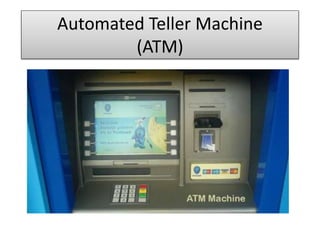
- 2. What is an ATM? • Automated teller machine (ATM) • Also called cash machines • Electronic computer terminals offering automated, computerized banking • Allows customers to perform transactions just as they would through a teller – Deposits, cash withdrawals, account transfers, check account balances
- 3. UML • The Unified Modeling Language (UML) is a very dominant modeling graphical language for specifying, constructing and documenting the artifacts of software system. • UML is simply another graphical representation of a common semantic model. • UML provides a comprehensive notation for the full lifecycle of object oriented development
- 4. Automated teller machine user interface.
- 6. Features of ATM Systems 1) A customer must be able to make a cash withdrawal from any suitable account linked to the card, in multiples of Rupees 100. Approval must be obtained from the bank before cash is dispensed. 2) A customer must be able to make a deposit to any account linked to the card, consisting of cash and/or checks in an envelope. 3) A customer must be able to make a transfer of money between any two accounts linked to the card. 4) A customer must be able to make a balance inquiry of any account linked to the card.
- 7. Object-Oriented Analysis • Object-oriented analysis looks at the problem domain, with the aim of producing a conceptual model of the information that exists in the area being analyzed. • Analysis models do not consider any implementation constraints or how the system is to be built. • The identified objects reflect entities and operations that are associated with the problem to be solved.
- 8. • UML static modeling for ATM systems This part describes the way that system should look. It analyses the structure and substructure of the modeled system based on objects, attributes, operations an relationships. • Use case modeling for ATM systems
- 9. Use Case Diagrams • We create a use case diagram to model the interactions between a system’s clients and its use cases. • Our requirements document supplies the actors—“ATM users should be able to view their account balance, withdraw cash and deposit funds.” • Therefore, the actor in each of the three use cases is the user who interacts with the ATM. An external entity—a real person—plays the part of the user to perform financial transactions.
- 10. Use case diagram for ATM system
- 11. Withdrawal Transaction Use Case • A withdrawal transaction asks the customer to choose a type of account to withdraw from : • Pre-conditions: The customer must have a valid ATM card and PIN. • Post-conditions: The customer receives the cash amount that he wanted to withdraw, with a receipt, if indicated. The customer’s account balance is updated in the system.
- 12. Specifications • Primary Actor: Customer • Stakeholders: - Customer: Wants quick, accurate withdrawal of cash - Bank: Wants to give fast, accurate and reliable service to the customer - Bank that owns ATM: (If not the same as the customer’s bank): Wants to charge the customer the correct amount of surcharge on the withdrawal. • ATM Administrator: Wants to ensure that the ATM always has sufficient cash for a predicted number of withdrawals per day.
- 13. Normal flow of events 1) The customer inserts ATM card into the ATM machine and enters PIN. 2) The system validates the ATM card and PIN . 3) The customer selects the ‘Cash Withdrawal’ option from the Options Menu. 4) The system prompts the customer to enter the amount of cash that he or she wants to withdraw. 5) The customer enters a cash amount and selects the ‘Submit’ option on the Cash Withdrawal Screen.
- 14. 6) The system validates the amount entered; checks account balance and that the machine has enough cash for the transaction, and asks the customer if he or she wants a receipt for the transaction. 7) The customer selects ‘Yes’ on the Receipts Screen. 8) The system ejects the ATM card, provides the cash, prints the receipt and updates the account balance of the customer in the system. Normal flow of events cont…..
- 15. Alternate flow of events: 1) The customer has entered invalid PIN The system prompts the customer to enter a valid PIN. 2) If ATM card is not compatible-The system rejects the ATM card and displays an error message. 3) The customer has entered an amount that exceeds the withdrawal limit. 4) The system rejects the transaction & displays an error message.
- 16. Deposit Transaction Use Case A deposit transaction asks the customer to choose a type of account to deposit to • Pre-conditions: The customer must have a valid ATM card and PIN. • Post-conditions: The customer receives the receipt of cash amount/ cheque that he has deposited. The customer’s account balance is updated in the system.
- 17. Specifications • Primary Actor: Customer • Stakeholders: – Customer: Wants quick, accurate withdrawal cash – Bank: Wants to give fast, accurate and reliable service to the customer – ATM Administrator: Wants to ensure that the ATM always has sufficient cash for a predicted number of withdrawals per day.
- 18. Class Diagram The basic structure of the class diagram arises from the responsibilities and relationships discovered when doing the CRC cards and Interaction Diagrams.
- 19. Class diagram for ATM system
- 21. Dynamic Modeling for ATM System It analyses the system behavior, including sequence and collaboration diagrams, activity diagram, and state diagram. State Diagrams : The transition between difference states is represented as an arrow between states, and a condition of that transition occurring may be added between square braced. This condition is called a guard
- 22. State diagram for ATM System
- 23. State diagram for transaction
- 24. Interaction Diagrams • UML defines two types of Interaction Diagram: the Sequence Diagram and the Collaboration Diagram. Interactions between objects are represented by interaction diagrams – both sequence and collaboration diagrams • Objects are drawn as rectangles and the lines between them indicate links – a link is an instance of an association. • Sequence diagram shows the relationship between classes arranged in a time sequence. Within a sequence diagram an object is shown in a box at the top.
- 25. Sequence diagram for PIN verification
- 26. UML modeling is a powerful language used to design for ATM system which is efficient & useful for the software developer to convert the above model through Object Oriented language. UML could be adopted for knowledge modeling as well. Conclusion