LEDSINO Digital LED Poster
•
0 likes•34 views

LED Poster using high-Quality LEDs, the brightness reaches ≥1000CD/㎡, which is 4 times of LCD Digital Poster and LED rear projection; higher color saturation, making the screen video image clearer, natural, delicate, visual impact stronger, will be better at publicizing your product.

Recommended
Recommended
More Related Content
Similar to LEDSINO Digital LED Poster
Similar to LEDSINO Digital LED Poster (20)
More from LEDSINO
Recently uploaded
Recently uploaded (20)
LEDSINO Digital LED Poster
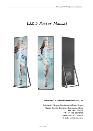
- 1. Shenzhen LEDSINO Optoelectronic Co.,Ltd. 第 1 / 21页 LA2.5 Poster Manual Shenzhen LEDSINO Optoelectronic Co.,Ltd. Building C, Tangtou First Industrial Zone, Shiyan Bao’an District, Shenzhen,Guangdong, China Zip code: 518108 Tel: +86-755-33075195 MOB:+86-13421345624 E-mail: leif@ledsino.com
- 2. Shenzhen LEDSINO Optoelectronic Co.,Ltd. 第 2 / 21页 Content Chapter 1 product introduction 1.1 Hardware 1.2 Product accessories 1.3 Operation environment 1.4 Principle and application 1.5 Installation Chapter 2 Parameter and structure 2.1 composition of machine 2.2 LED module 2.3 Power supply 2.4 Receiving card 2.5 Machine drawing Chapter 3 Change for disabled component 3.1 Change module 3.2 Change sending card and power supply 3.3 Change receiving card 3.4 Change HUB Chapter 4 Attention
- 3. Shenzhen LEDSINO Optoelectronic Co.,Ltd. 第 3 / 21页 Chapter 1 Product introduction §1.1 Hardware 1.1.1 A series advertising machine 1.1.2 Stand base/hanging structure 1.1.3 1PC(for synchronous control use, with software, with HDMI out port for graphic card) 1.1.4 mobile phone/ipad(asynchronous control use, download APP software) Remark: can switch between synchronous and asynchronous, can select synchronous or asynchronous §1.2component of product item A2.5 poster Spare part power cable Standard 1.5m power cable Stand base For stand use on the floor Hanging bar For hanging the machine technology Control system Nova Module design Led and ic driver all in one Panel design Patented design Calibration Brightness and color calibration §1.3 Operation environment 1.3.1 working temperature : 0 - +40℃ ; 1.3.2 Humidity: 0 - 70%RH,no freezing; §1.4 Principle and application environment 1.4.1 Principle: to control brightness and color of the LED lamp by sending card, receiving card and control software, realize different photos and video playing 1.4.2 Application environment: Supermarket, stage, entrance of the metro and airport, and so on.
- 4. Shenzhen LEDSINO Optoelectronic Co.,Ltd. 第 4 / 21页 §1.5 Installation 1.5.1 Hanging Use self-tapping or explosive bolt to fix the hanging bar to the structure or ceiling Use M10 nut to connect panel and hanging bar Vertical/horizontal hanging
- 5. Shenzhen LEDSINO Optoelectronic Co.,Ltd. 第 5 / 21页 1.5.2 Standing Adjust the length of the beam to control the standing angle 1.install the supporter of 2. install the bracket of the standbase
- 6. Shenzhen LEDSINO Optoelectronic Co.,Ltd. 第 6 / 21页 1.5.3 Mounting installation Hange r Based on the real environment to mount it on the wall, and then attach the panle with hanging screw on the hanger Hanging screw Creative installation mode
- 7. Shenzhen LEDSINO Optoelectronic Co.,Ltd. 第 7 / 21页 Chapter 2 Parameters and structure §2.1 A Panel and parameters Composition of panel: 18pcs LED modules, 3pcs receiving card, 2pcs 400W power supply, 1pc sending card, 3pcs HUB. Panel structure, plastic back cover, Aluminum back cover, acrylic front cover Composition of module: LED lamp, PCB board, ic driver, connectors, shell, HUB 2.1.1 Panel composition NO. Item QTY(PCS) 1 LED module 18 2 Receiving card 3 3 HUB 3 4 Power supply 2 5 Sending card 1 6 Power box 1 7 Panel back cover 1 8 Panel structure 1 9 Stand base 1 9 1 2 3 5 4 8 7 6
- 8. Shenzhen LEDSINO Optoelectronic Co.,Ltd. 第 8 / 21页 2.1.2 Parameter LED encapsulation SMD 2020 Pixel configuration 1R1G1B Pixel pitch 2.571mm Brightness 1000nits Density 151284pixels /㎡ Weight 35kg/pc(without stand) Panel size 614*1982*40 mm Panel material Brushed aluminum +metal plate Resolution 224*756 dots IP IP30(front/rear) LED module size 288*216mm Viewing angle H: 140°/V:140° Display area 1.12 ㎡ Contrast ratio 4000:1 Scan mode 1/28 scan Brightness control 256levels IC driver 2053 Storage temperature -20℃- +60℃/0- 80%RH Working temperature 0℃- +40℃/0-70%RH Frequency 50Hz/60Hz Refresh rate 2880 Processing 14bit Display size 576*1944 Gray scale 16384 levels per color Color 4.4trillion Life time 100,000 Hours Power consumption 350W/122W Input voltage 110~220V Installation mode hanging/stand Maintenance Front and back Control system Asynchronous/synchrono us Input power frequency 50-60Hz Control card Nova T3 Control mode Internet/WIFI/4G Stand angle 0~15°
- 9. Shenzhen LEDSINO Optoelectronic Co.,Ltd. 第 9 / 21页 §2.2 Module composition and parameter 2.2.1 Composition of module 1.data power port;2.magnet of module;3.structure of shell;4.positioning pole;5.direction 6. front maintenance iron;7.module code;8.LED lamp 2.2.2 Module parameter A2.57 module parameter NO. Item Parameter 1 Model A2.57 2 Pitch 2.571mm 3 Density 151284 4 Size 288*216mm 5 LED encapsulation SDM 2020 6 Horizontal viewing angle 140 7 Vertical viewing angle 140 8 Resolution 112*84 FrontBack 1 2 3 4 5 6 7 5
- 10. Shenzhen LEDSINO Optoelectronic Co.,Ltd. 第 10 / 21页 2.2.3 Module troubleshooting and repairing Analysis: all black, white, flicker, scratch and many leds failure appears, then need to repair the module. Steps: 1. Turn off power supply, take off front cover, 2. Take off the disabled module by tool, 3. Change the new module. Attention: wear anti-static glove when operation §2.3 Power supply Turn off power, then maintain it Attention: don’t mix the position of live line, neutral line and ground line Analysis: When judge whether there is power output or not, should use the AVO meter( or other test tool), same time should check whether there is flash or last lighting of the indicator of the power supply Internal VCC + DC VCC - DC AC 110- 220v VCC+ DC OUT PUT VCC - DC OUT PUT 5V 0V 220V AC IN PUT Live line(Brown) Neutral line(Blue) Ground line(Yellow) Earth line 黄
- 11. Shenzhen LEDSINO Optoelectronic Co.,Ltd. 第 11 / 21页 §2.4 Receiving card Analysis: When there is signal and working normally, the indicator of the receiving card will be flash normally, if there is disabling or no signal input, there will be abnormal flash, last lighting or not lighting of the indicator Attention: the power should be turned off when replace or maintain the receiving card. After changing the new receiving card, should upload the data of the machine(the machine is connected with the computer by internet cable, open the software to read the data of the module, then upload the data to the receiving card). Please keep clean of the slot of receiving card and HUB when install or tear down the receiving card. After installation, please check whether there is loosening or other problem, then fixed by screw.
- 12. Shenzhen LEDSINO Optoelectronic Co.,Ltd. 第 12 / 21页 §2.5 Panel diagram
- 13. Shenzhen LEDSINO Optoelectronic Co.,Ltd. 第 13 / 21页 Chapter 3. Change for disabled component §3.1 Change LED module 1. 1.Tear down the angle-pressing block from any corner of the machine 2. Tear down the aluminum bar
- 14. Shenzhen LEDSINO Optoelectronic Co.,Ltd. 第 14 / 21页 4. Take off the module by the magnetic tool “ON” “ON” 3. Take away the a front cover
- 15. Shenzhen LEDSINO Optoelectronic Co.,Ltd. 第 15 / 21页 §3.2 Change sending card and power supply 1.Use the cross type screw driver to loosen the screw of the power box cover Vertically 90°to take the handle
- 16. Shenzhen LEDSINO Optoelectronic Co.,Ltd. 第 16 / 21页 1. Power cable 2.output internet cable 3. WIFI cable 4. Synchronous/asynchronous switcher cable 5. indicator 2. Pull up the cables of the receiving card(remember the position and order of the cables 3. Tear down the screw and take off the old sending card, change the new sending card 4 1 2 5 3
- 17. Shenzhen LEDSINO Optoelectronic Co.,Ltd. 第 17 / 21页 5 Use M3 socket wrench to tear off the screw of the power supply and change the new power supply Cross type screw driver 4.Tear down the AC line and DC line of the power supply Quick plug in/off port
- 18. Shenzhen LEDSINO Optoelectronic Co.,Ltd. 第 18 / 21页 §3.3 Change receiving card 1.Tear down the back cover with same position the disabled receiving card 2. Change the new receiving card and put back the led module
- 19. Shenzhen LEDSINO Optoelectronic Co.,Ltd. 第 19 / 21页 §3.4 Change HUB 2. Tear down internet cable, power cable, tear down the 8pcs screws on the HUB and change the new one 1. Tear down the back cover with same position of the disabled HUB
- 20. Shenzhen LEDSINO Optoelectronic Co.,Ltd. 第 20 / 21页 Chapter 4. Attention 1.Attention for synchronous operation By the Synchronous/asynchronous system switcher to realize Synchronous/asynchronous switch When the indicator is on, it is the synchronous state, connect to the HDMI cable and it will display the content from the control computer. 1. Attention of asynchronous operation Make sure the indicator is off from the Synchronous/asynchronous system switcher, otherwise there will be no content display in the screen or display abnormally 2. After tear down or change the card, there will be no abnormal display for the machine, then need to send the diagram by computer and mobile phone, after sending the diagram, if the display is still abnormal, change to port 2 to send the diagram from the software is OK Synchronous/asy nchronous system switcher
- 21. Shenzhen LEDSINO Optoelectronic Co.,Ltd. 第 21 / 21页