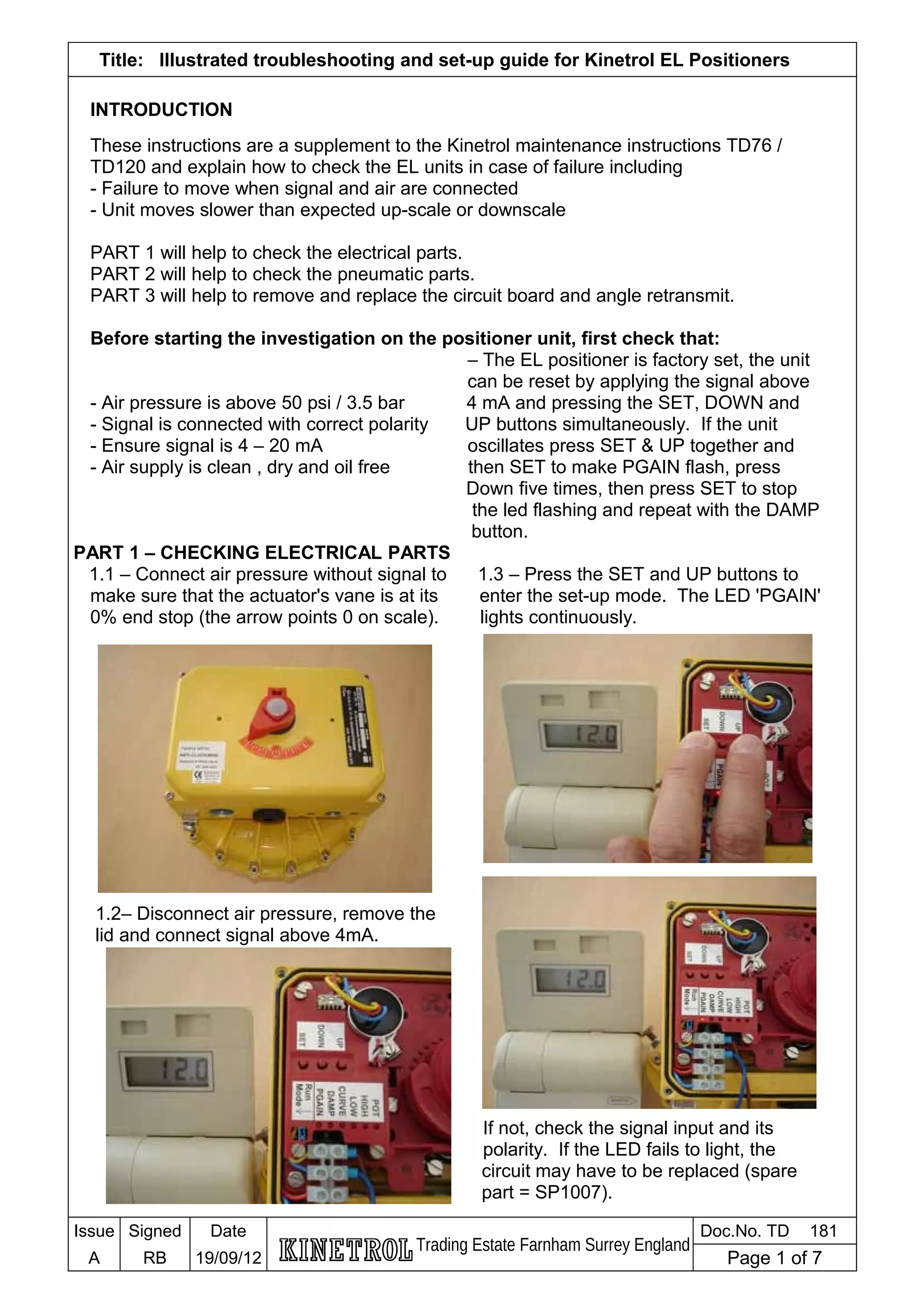
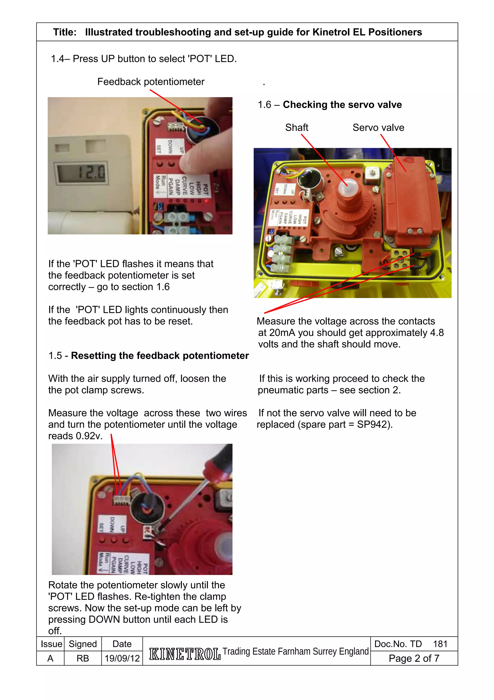
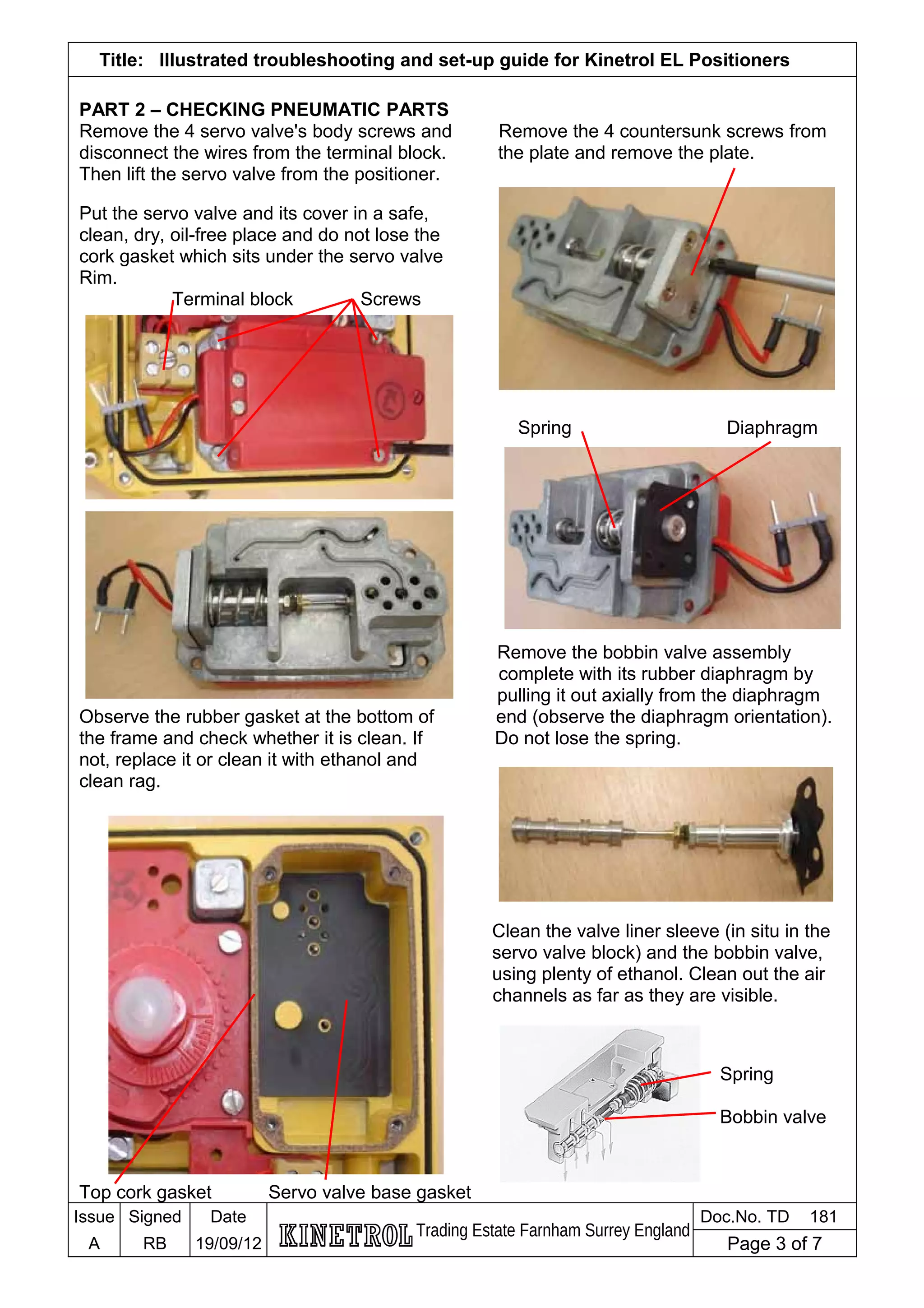
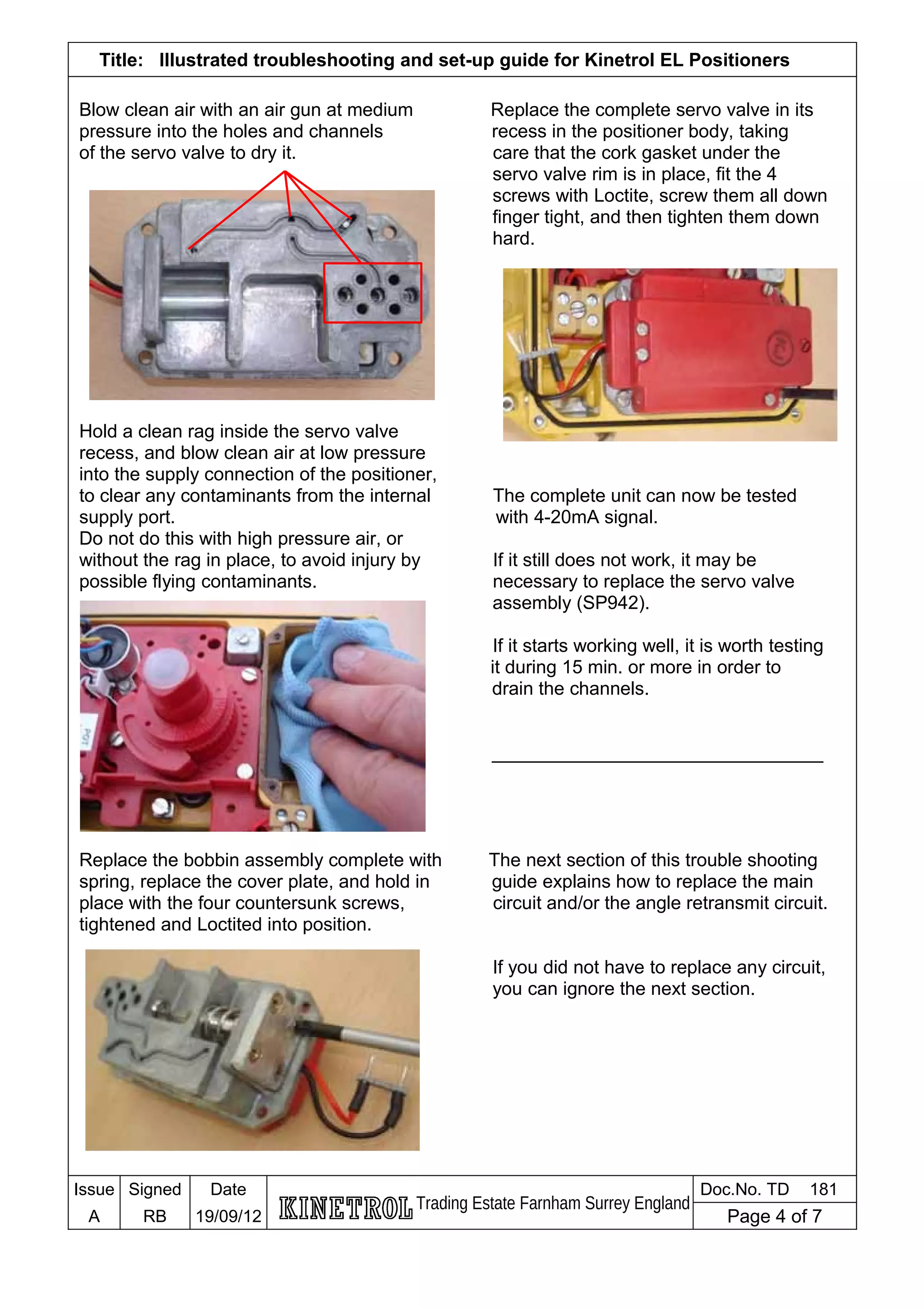
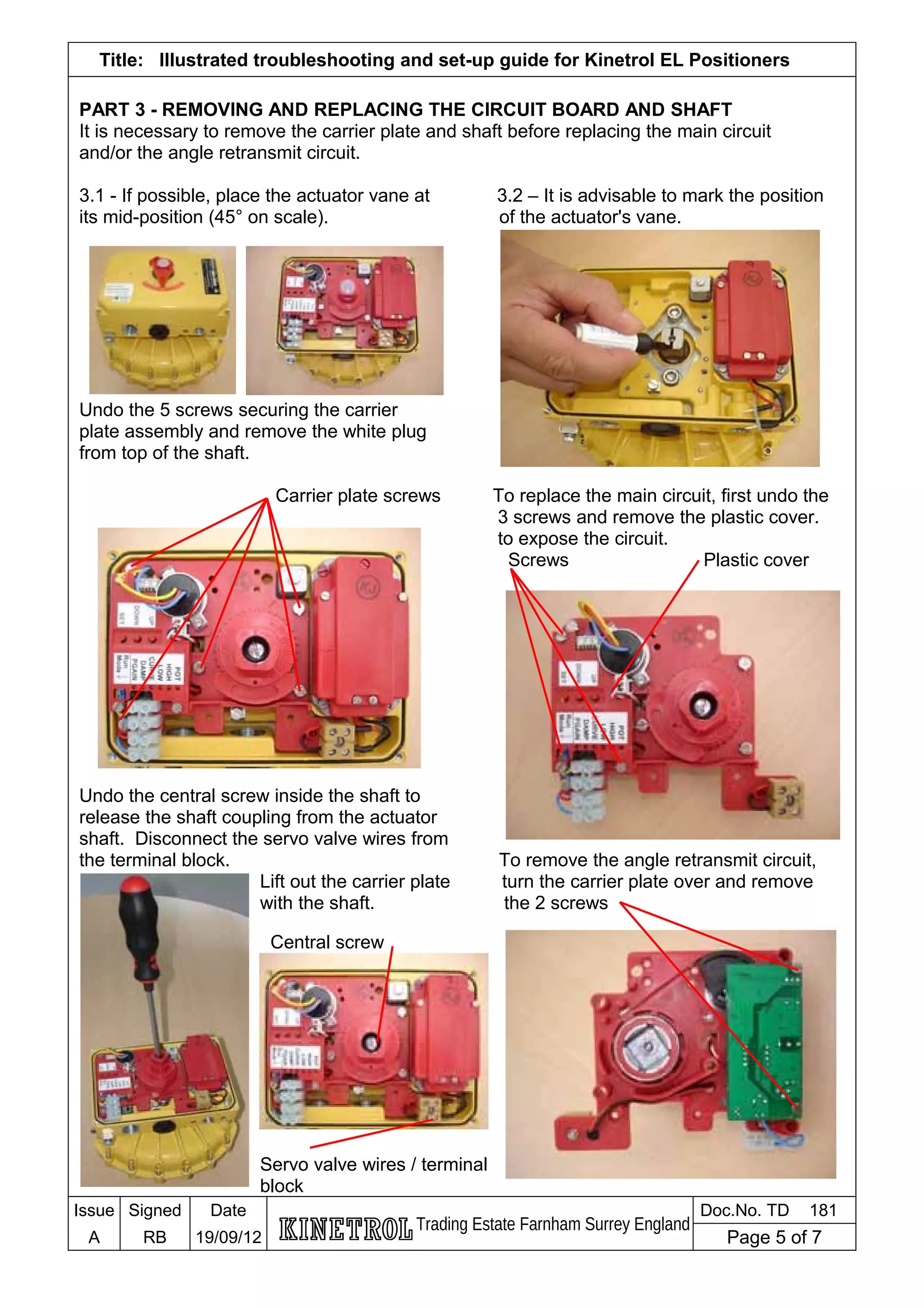
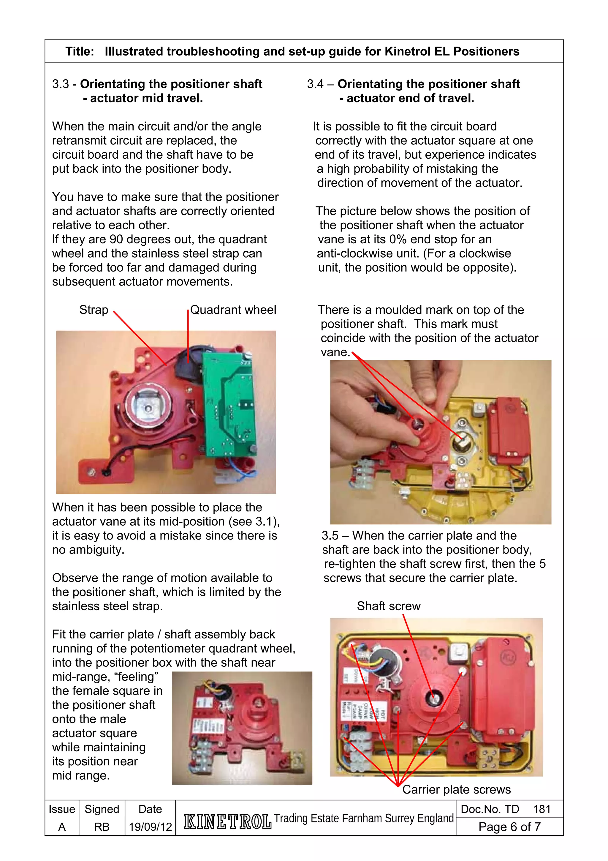
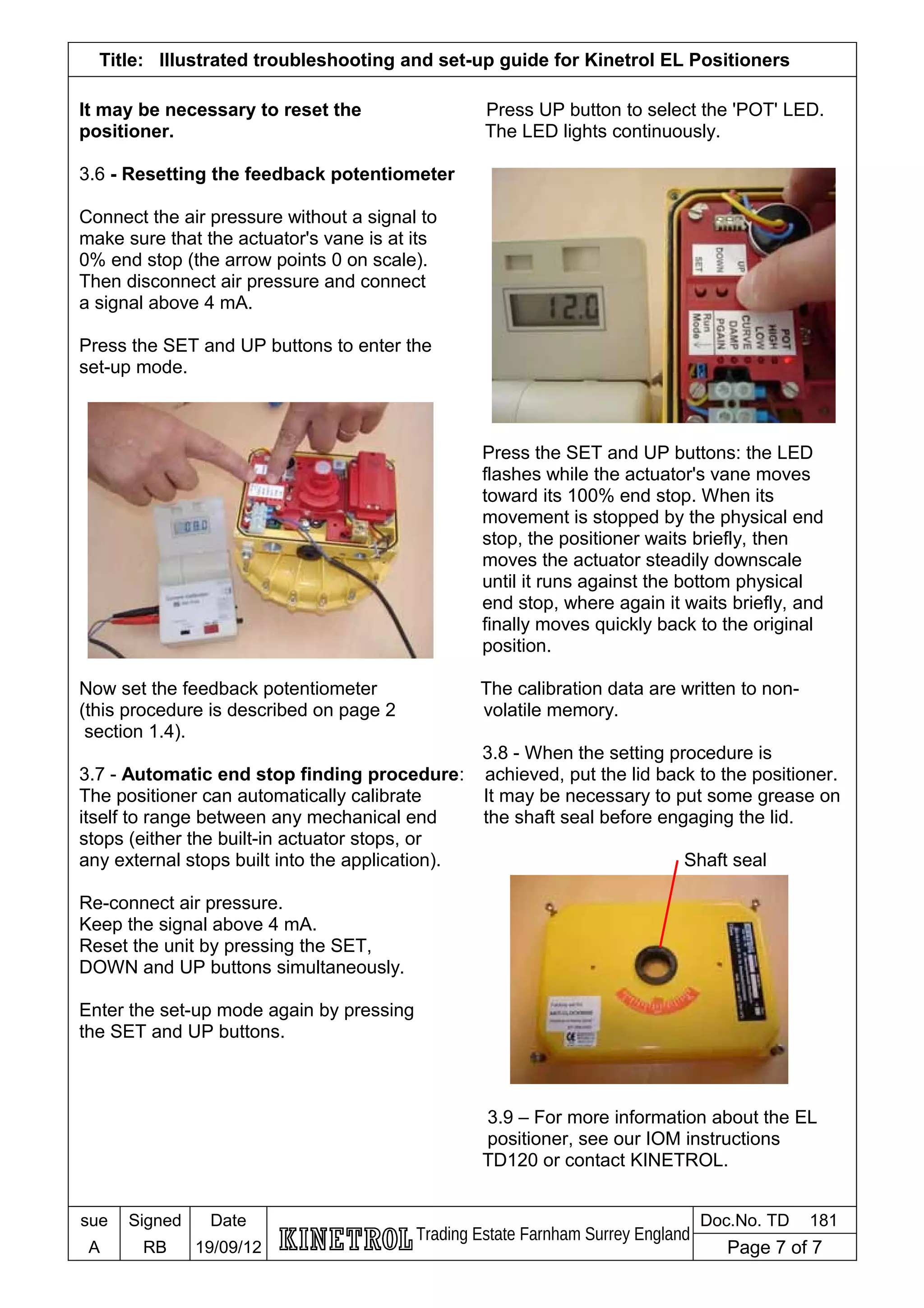
The Kinetrol EL Positioner operates by modulating the percent opening / closing of a valve or damper by converting an electrical signal to a pneumatic output, which in turn, regulates the position of a pneumatic actuator.
In terms of response and accuracy, the EL Positioner is arguably one of the best electro-pneumatic positioners in the world, particularly when used in tandem with a Kinetrol vane actuator.
This document provides an illustrated troubleshooting and set-up guide for the EL electro-pneumatic positioner and is available to support the all the units installed in chemical, petro-chemical, water treatment, power generation and other applications across the world.
Block diagram reduction techniques in control systems.ppt
Illustrated Troubleshooting & Set Up Guide for Kinetrol EL Positioners
1. Title: Illustrated troubleshooting and set-up guide for Kinetrol EL Positioners
INTRODUCTION
These instructions are a supplement to the Kinetrol maintenance instructions TD76 /
TD120 and explain how to check the EL units in case of failure including
- Failure to move when signal and air are connected
- Unit moves slower than expected up-scale or downscale
PART 1 will help to check the electrical parts.
PART 2 will help to check the pneumatic parts.
PART 3 will help to remove and replace the circuit board and angle retransmit.
Before starting the investigation on the positioner unit, first check that:
– The EL positioner is factory set, the unit
can be reset by applying the signal above
- Air pressure is above 50 psi / 3.5 bar 4 mA and pressing the SET, DOWN and
- Signal is connected with correct polarity UP buttons simultaneously. If the unit
- Ensure signal is 4 – 20 mA oscillates press SET & UP together and
- Air supply is clean , dry and oil free then SET to make PGAIN flash, press
Down five times, then press SET to stop
the led flashing and repeat with the DAMP
button.
PART 1 – CHECKING ELECTRICAL PARTS
1.1 – Connect air pressure without signal to 1.3 – Press the SET and UP buttons to
make sure that the actuator's vane is at its enter the set-up mode. The LED 'PGAIN'
0% end stop (the arrow points 0 on scale). lights continuously.
1.2– Disconnect air pressure, remove the
lid and connect signal above 4mA.
If not, check the signal input and its
polarity. If the LED fails to light, the
circuit may have to be replaced (spare
part = SP1007).
Issue Signed Date
Trading Estate Farnham Surrey England
Doc.No. TD 181
A RB 19/09/12 Page 1 of 7
2. Title: Illustrated troubleshooting and set-up guide for Kinetrol EL Positioners
1.4– Press UP button to select 'POT' LED.
Feedback potentiometer .
1.6 – Checking the servo valve
Shaft Servo valve
If the 'POT' LED flashes it means that
the feedback potentiometer is set
correctly – go to section 1.6
If the 'POT' LED lights continuously then
the feedback pot has to be reset. Measure the voltage across the contacts
at 20mA you should get approximately 4.8
volts and the shaft should move.
1.5 - Resetting the feedback potentiometer
With the air supply turned off, loosen the If this is working proceed to check the
the pot clamp screws. pneumatic parts – see section 2.
Measure the voltage across these two wires If not the servo valve will need to be
and turn the potentiometer until the voltage replaced (spare part = SP942).
reads 0.92v.
Rotate the potentiometer slowly until the
'POT' LED flashes. Re-tighten the clamp
screws. Now the set-up mode can be left by
pressing DOWN button until each LED is
off.
Issue Signed Date
Trading Estate Farnham Surrey England
Doc.No. TD 181
A RB 19/09/12 Page 2 of 7
3. Title: Illustrated troubleshooting and set-up guide for Kinetrol EL Positioners
PART 2 – CHECKING PNEUMATIC PARTS
Remove the 4 servo valve's body screws and Remove the 4 countersunk screws from
disconnect the wires from the terminal block. the plate and remove the plate.
Then lift the servo valve from the positioner.
Put the servo valve and its cover in a safe,
clean, dry, oil-free place and do not lose the
cork gasket which sits under the servo valve
Rim.
Terminal block Screws
Spring Diaphragm
Remove the bobbin valve assembly
complete with its rubber diaphragm by
pulling it out axially from the diaphragm
Observe the rubber gasket at the bottom of end (observe the diaphragm orientation).
the frame and check whether it is clean. If Do not lose the spring.
not, replace it or clean it with ethanol and
clean rag.
Clean the valve liner sleeve (in situ in the
servo valve block) and the bobbin valve,
using plenty of ethanol. Clean out the air
channels as far as they are visible.
Spring
Bobbin valve
Top cork gasket Servo valve base gasket
Issue Signed Date
Trading Estate Farnham Surrey England
Doc.No. TD 181
A RB 19/09/12 Page 3 of 7
4. Title: Illustrated troubleshooting and set-up guide for Kinetrol EL Positioners
Blow clean air with an air gun at medium Replace the complete servo valve in its
pressure into the holes and channels recess in the positioner body, taking
of the servo valve to dry it. care that the cork gasket under the
servo valve rim is in place, fit the 4
screws with Loctite, screw them all down
finger tight, and then tighten them down
hard.
Hold a clean rag inside the servo valve
recess, and blow clean air at low pressure
into the supply connection of the positioner,
to clear any contaminants from the internal The complete unit can now be tested
supply port. with 4-20mA signal.
Do not do this with high pressure air, or
without the rag in place, to avoid injury by If it still does not work, it may be
possible flying contaminants. necessary to replace the servo valve
assembly (SP942).
If it starts working well, it is worth testing
it during 15 min. or more in order to
drain the channels.
________________________________
Replace the bobbin assembly complete with The next section of this trouble shooting
spring, replace the cover plate, and hold in guide explains how to replace the main
place with the four countersunk screws, circuit and/or the angle retransmit circuit.
tightened and Loctited into position.
If you did not have to replace any circuit,
you can ignore the next section.
Issue Signed Date
Trading Estate Farnham Surrey England
Doc.No. TD 181
A RB 19/09/12 Page 4 of 7
5. Title: Illustrated troubleshooting and set-up guide for Kinetrol EL Positioners
PART 3 - REMOVING AND REPLACING THE CIRCUIT BOARD AND SHAFT
It is necessary to remove the carrier plate and shaft before replacing the main circuit
and/or the angle retransmit circuit.
3.1 - If possible, place the actuator vane at 3.2 – It is advisable to mark the position
its mid-position (45° on scale). of the actuator's vane.
Undo the 5 screws securing the carrier
plate assembly and remove the white plug
from top of the shaft.
Carrier plate screws To replace the main circuit, first undo the
3 screws and remove the plastic cover.
to expose the circuit.
Screws Plastic cover
Undo the central screw inside the shaft to
release the shaft coupling from the actuator
shaft. Disconnect the servo valve wires from
the terminal block. To remove the angle retransmit circuit,
Lift out the carrier plate turn the carrier plate over and remove
with the shaft. the 2 screws
Central screw
Servo valve wires / terminal
block
Issue Signed Date
Trading Estate Farnham Surrey England
Doc.No. TD 181
A RB 19/09/12 Page 5 of 7
6. Title: Illustrated troubleshooting and set-up guide for Kinetrol EL Positioners
3.3 - Orientating the positioner shaft 3.4 – Orientating the positioner shaft
- actuator mid travel. - actuator end of travel.
When the main circuit and/or the angle It is possible to fit the circuit board
retransmit circuit are replaced, the correctly with the actuator square at one
circuit board and the shaft have to be end of its travel, but experience indicates
put back into the positioner body. a high probability of mistaking the
direction of movement of the actuator.
You have to make sure that the positioner
and actuator shafts are correctly oriented The picture below shows the position of
relative to each other. the positioner shaft when the actuator
If they are 90 degrees out, the quadrant vane is at its 0% end stop for an
wheel and the stainless steel strap can anti-clockwise unit. (For a clockwise
be forced too far and damaged during unit, the position would be opposite).
subsequent actuator movements.
Strap Quadrant wheel There is a moulded mark on top of the
positioner shaft. This mark must
coincide with the position of the actuator
vane.
When it has been possible to place the
actuator vane at its mid-position (see 3.1),
it is easy to avoid a mistake since there is 3.5 – When the carrier plate and the
no ambiguity. shaft are back into the positioner body,
re-tighten the shaft screw first, then the 5
Observe the range of motion available to screws that secure the carrier plate.
the positioner shaft, which is limited by the
stainless steel strap. Shaft screw
Fit the carrier plate / shaft assembly back
running of the potentiometer quadrant wheel,
into the positioner box with the shaft near
mid-range, “feeling”
the female square in
the positioner shaft
onto the male
actuator square
while maintaining
its position near
mid range.
Carrier plate screws
Issue Signed Date
Trading Estate Farnham Surrey England
Doc.No. TD 181
A RB 19/09/12 Page 6 of 7
7. Title: Illustrated troubleshooting and set-up guide for Kinetrol EL Positioners
It may be necessary to reset the Press UP button to select the 'POT' LED.
positioner. The LED lights continuously.
3.6 - Resetting the feedback potentiometer
Connect the air pressure without a signal to
make sure that the actuator's vane is at its
0% end stop (the arrow points 0 on scale).
Then disconnect air pressure and connect
a signal above 4 mA.
Press the SET and UP buttons to enter the
set-up mode.
Press the SET and UP buttons: the LED
flashes while the actuator's vane moves
toward its 100% end stop. When its
movement is stopped by the physical end
stop, the positioner waits briefly, then
moves the actuator steadily downscale
until it runs against the bottom physical
end stop, where again it waits briefly, and
finally moves quickly back to the original
position.
Now set the feedback potentiometer The calibration data are written to non-
(this procedure is described on page 2 volatile memory.
section 1.4).
3.8 - When the setting procedure is
3.7 - Automatic end stop finding procedure: achieved, put the lid back to the positioner.
The positioner can automatically calibrate It may be necessary to put some grease on
itself to range between any mechanical end the shaft seal before engaging the lid.
stops (either the built-in actuator stops, or
any external stops built into the application). Shaft seal
Re-connect air pressure.
Keep the signal above 4 mA.
Reset the unit by pressing the SET,
DOWN and UP buttons simultaneously.
Enter the set-up mode again by pressing
the SET and UP buttons.
3.9 – For more information about the EL
positioner, see our IOM instructions
TD120 or contact KINETROL.
sue Signed Date
Trading Estate Farnham Surrey England
Doc.No. TD 181
A RB 19/09/12 Page 7 of 7