SlideShare a Scribd company logo
1 of 4
Download to read offline
© 2013 UTC Fire & Security. All rights reserved. 1 / 4 P/N 3101100 • REV 03 • REB 25JAN13
SA-ETH Ethernet Interface Card
Installation Sheet
EN FR
EN: Installation Sheet
Operation
The SA-ETH card provides a standard 10/100 Base-T Ethernet
network connection for connecting to a local network. The card
can be used for uploading and downloading panel
configuration, history, and current status to a PC running the
configuration utility or connect to a compatible central
monitoring station receiver over a network.
Installation
The Ethernet card is installed on the plastic assembly and
connects to the main circuit board via a ribbon cable.
Note: The Ethernet card must be configured through
programming for proper operation.
To install the Ethernet card:
1. Power down the panel and disconnect the batteries.
2. Locate the card slot on the plastic assembly behind the
main circuit board and connector J1 on the main circuit
board (at the top-right of the main board).
3. Slide the card into the slot on the plastic assembly as
show in the diagram.
4. Attach the card to the plastic assembly using two #6
plastite screws as show in the diagram.
5. Connect the ribbon cable (P/N 7140189) from the card to
connector J1 on the main circuit board. J1 is located on
the top-right of the main circuit board.
6. Connect the network cable. See “Wiring.”
7. Power up the panel and connect the batteries.
Figure 1: Slide the card into its slot
Ethernet card
Top-right of main
circuit board
Card slot on
plastic assembly
Figure 2: Screw the card in place and connect the ribbon cable
To connector J1 on
main circuit board
(top-right of board)
Ribbon cable
#6 plastite
screws
2 / 4 P/N 3101100 • REV 03 • REB 25JAN13
Wiring
Note: A crossover cable or a straight through cable can be
used.
Figure 3: SA-ETH wiring
Network cable
Ethernet card
To network
connection
(PC, router, switch, etc.)
SA-ETH LEDs
There are four LEDs on the card that indicate card and network
status.
Figure 4: LEDs
Ethernet card
LED 1 (DS1): Link
LED 2 (DS2): Speed
LED 3 (DS3): Duplex
LED 4 (DS4): Collision
SA-ETH compatibility
The SA-ETH is listed for use with the following DACRs.
Receiver Models Formats
Osborne-Hoffman OH2000 and OH2000E
(with a OH-TCP/IP-LC
card installed) (see note
below)
Contact ID
Note: If the line card firmware is V2.2 or later, use the default CMS
network settings. If the line card firmware is V2.2 or earlier, the
Timeout Seconds must be set to 60, the Hello Timer set to 75, and the
Line Cut timer in the line card itself set to 175 seconds. If you are
unsure of the firmware version in the receiver or there are
communication faults between the panel and the receiver, then these
settings are recommended.
Specifications
Ethernet 10/100 Base-T
Connection mode Auto negotiation
Operating voltage 24 VDC
Operating current Standby/Alarm: 34 mA
Max.: 41 mA
Max. wire runs 200 feet (60 m), Cat 5 cable (panel to
communication equipment)
Cat 5 cable connector RJ-45
IP address (default) 192.168.001.003
Subnet mask (default) 255.255.255.0
Gateway (default) 000.000.000.000
Operating environment
Temperature
Humidity
32 to 120°F (0 to 49°C)
0 to 93% RH, noncondensing at 90°F
(32°C)
FR: Fiche D'Installation
Fonctionnement
La carte SA-ETH procure une connexion à un réseau Ethernet
10/100 à paire torsadée (Base-T) standard pour un
branchement à un réseau local. La carte permet de télécharger
en amont ou en aval la configuration, l’historique et l’état actuel
du panneau de commande à un ordinateur exécutant l’utilitaire
de configuration ou à se brancher à un récepteur d’une
centrale de surveillance compatible au moyen d’un réseau.
Installation
La carte Ethernet est installée sur le montant en plastique et
est branchée à la carte de circuits imprimés principale à l’aide
d’un câble ruban.
Remarque : Pour assurer un bon fonctionnement, la carte
Ethernet doit être activée et configurée par programmation.
Installation de la carte Ethernet :
1. Coupez l’alimentation au panneau et débranchez les piles.
2. Localisez la coche de la carte sur le montant en plastique
derrière la carte de circuits imprimés et le connecteur J3
(coin supérieur droit de la carte de circuits imprimés
principale).
3. Glissez la carte dans la coche du montant en plastique
comme indiqué dans le diagramme.
4. Attachez la carte au montant en plastique à l’aide de deux
vis plastie no 6 comme indiqué dans le diagramme.
P/N 3101100 • REV 03 • REB 25JAN13 3 / 4
5. Branchez le câble ruban (P/N 7140189) de la carte au
connecteur J1 de la carte de circuits imprimés principale.
Le connecteur J1 est situé dans le coin supérieur droit de
la carte de circuits imprimés.
6. Branchez le câble de réseau. Voir la section « Filage ».
7. Rétablissez l’alimentation au panneau et rebranchez les
piles.
Figure 1 : Glissez la carte dans la fente
Carte Ethernet
Coin
droit de la carte de
circuits
supérieure
imprimés
Fentes de la carte
du montage plastique
Figure 2 : Vissez la carte en place et branchez le câble ruban
Vis plastie n 6
o
Au connecteur J1 sur
carte de circuits
oin supérieur droit)
imprimés
(c
Câble ruban
Filage
Remarque : On peut utiliser un câble en croisé ou
ininterrompu.
Figure 3 : Filage du SA-ETH
Câble de réseau
Carte Ethernet
À la connexion réseau
(PC, routeur, commutateur, etc.)
Voyants DEL de la SA-ETH
Il y a quatre voyants DEL sur la carte qui indiquent l’état de la
carte et du réseau.
Figure 4 : Voyants DEL
Carte Ethernet
DEL 1 (lien)
DEL 2 (vitesse)
DEL 3 (duplex)
DEL 4 (collision)
Compatibilité de la SA-ETH
Le SA-ETH est utilisable avec les DACR ci-dessous.
Récepteur Modèles Formats
Osborne-Hoffman OH2000 et OH2000E
(avec une carte OH-
TCP/IP-LC installée) (voir
la remarque ci-dessous)
Identification de
contact
Remarque : Si le micrologiciel de la carte de ligne est une version
V2,2 ou antérieure, utilisez le réglage de réseau CMS par défaut. Si le
micrologiciel de la carte de ligne est une version V2,2 ou plus récente,
les secondes des temps morts doivent être réglées à 60, la minuterie
Hello à 75 et la minuterie de coupure de ligne dans la carte elle-même
à 175 secondes. Si vous n’êtes pas certain de la version du
micrologiciel dans le récepteur ou qu’il y a des erreurs de
communication entre le panneau de commande et le récepteur, on
recommande des réglages.
4 / 4 P/N 3101100 • REV 03 • REB 25JAN13
Fiche technique
Ethernet 10/100 Base-T
Mode de connexion Négociation automatique
Tension de service 24 VDC
Courant opérationnel En attente et alarme : 34 mA
Maximum : 41 mA
Longueur maximale du
filage
60 mètres (200 pi), câble de catégorie 5
(du panneau à l’équipement de
communication)
Connecteur de câble de
catégorie 5
RJ-45
Adresse de protocole
Internet (par défaut)
192.168.001.003
Filtre d’adresse locale (par
défaut)
255.255.255.0
Passerelle (par défaut) 000.000.000.000
Environnement
opérationnel
Température
Humidité
0 à 49 °C (32 à 120 °F)
0 à 93 % RH, non-condensation à
32 °C (90 °F)

More Related Content

Similar to Edwards Signaling SA-ETH Installation Manual

Fpga handout
Fpga handoutFpga handout
Fpga handoutassnad
 
Edwards Signaling SA-DACT Installation Manual
Edwards Signaling SA-DACT Installation ManualEdwards Signaling SA-DACT Installation Manual
Edwards Signaling SA-DACT Installation ManualJMAC Supply
 
étapes de réalisation réseau local
étapes de réalisation réseau localétapes de réalisation réseau local
étapes de réalisation réseau localFAN COMPUTING
 
Rapport dridi sahar_tunisie_telecom
Rapport dridi sahar_tunisie_telecomRapport dridi sahar_tunisie_telecom
Rapport dridi sahar_tunisie_telecomsahar dridi
 
Ch3 tph
Ch3 tphCh3 tph
Ch3 tphsdamhk
 
SDH technology
SDH technologySDH technology
SDH technologymarwan23
 
API et Supervision industrielle
API et Supervision industrielle API et Supervision industrielle
API et Supervision industrielle sarah Benmerzouk
 
Cour installation electrique bedoui iset-ksar-hellal
Cour installation electrique bedoui iset-ksar-hellalCour installation electrique bedoui iset-ksar-hellal
Cour installation electrique bedoui iset-ksar-hellalhassen_be
 
204081791-Protocole-Frame-Relay.pptx
204081791-Protocole-Frame-Relay.pptx204081791-Protocole-Frame-Relay.pptx
204081791-Protocole-Frame-Relay.pptxFatimazogr
 
Manuel d'installation Sagem fast 2604
Manuel d'installation Sagem fast 2604Manuel d'installation Sagem fast 2604
Manuel d'installation Sagem fast 2604ventdest
 
Relais bluetooth - Balance connectée
Relais bluetooth - Balance connectéeRelais bluetooth - Balance connectée
Relais bluetooth - Balance connectéePeronnin Eric
 
Formation Bus de Terrain _Partie 3_ Ethernet Industriel pour Valve Terminals
Formation Bus de Terrain  _Partie 3_  Ethernet Industriel pour Valve TerminalsFormation Bus de Terrain  _Partie 3_  Ethernet Industriel pour Valve Terminals
Formation Bus de Terrain _Partie 3_ Ethernet Industriel pour Valve TerminalsWojciech GOMOLKA
 
Atelier Reseaux informatiques
Atelier Reseaux informatiquesAtelier Reseaux informatiques
Atelier Reseaux informatiquesfulgence
 

Similar to Edwards Signaling SA-ETH Installation Manual (20)

Fpga handout
Fpga handoutFpga handout
Fpga handout
 
Edwards Signaling SA-DACT Installation Manual
Edwards Signaling SA-DACT Installation ManualEdwards Signaling SA-DACT Installation Manual
Edwards Signaling SA-DACT Installation Manual
 
Le câble rj
Le câble rjLe câble rj
Le câble rj
 
étapes de réalisation réseau local
étapes de réalisation réseau localétapes de réalisation réseau local
étapes de réalisation réseau local
 
Rapport dridi sahar_tunisie_telecom
Rapport dridi sahar_tunisie_telecomRapport dridi sahar_tunisie_telecom
Rapport dridi sahar_tunisie_telecom
 
Chapitre 4 - Réseaux Ethernet
Chapitre 4 - Réseaux EthernetChapitre 4 - Réseaux Ethernet
Chapitre 4 - Réseaux Ethernet
 
Ch3 tph
Ch3 tphCh3 tph
Ch3 tph
 
SDH technology
SDH technologySDH technology
SDH technology
 
SDH
SDHSDH
SDH
 
API et Supervision industrielle
API et Supervision industrielle API et Supervision industrielle
API et Supervision industrielle
 
Cour installation electrique bedoui iset-ksar-hellal
Cour installation electrique bedoui iset-ksar-hellalCour installation electrique bedoui iset-ksar-hellal
Cour installation electrique bedoui iset-ksar-hellal
 
204081791-Protocole-Frame-Relay.pptx
204081791-Protocole-Frame-Relay.pptx204081791-Protocole-Frame-Relay.pptx
204081791-Protocole-Frame-Relay.pptx
 
Mini projet 3t2i se
Mini projet 3t2i seMini projet 3t2i se
Mini projet 3t2i se
 
Manuel d'installation Sagem fast 2604
Manuel d'installation Sagem fast 2604Manuel d'installation Sagem fast 2604
Manuel d'installation Sagem fast 2604
 
Relais bluetooth - Balance connectée
Relais bluetooth - Balance connectéeRelais bluetooth - Balance connectée
Relais bluetooth - Balance connectée
 
Ccna1
Ccna1Ccna1
Ccna1
 
Formation Bus de Terrain _Partie 3_ Ethernet Industriel pour Valve Terminals
Formation Bus de Terrain  _Partie 3_  Ethernet Industriel pour Valve TerminalsFormation Bus de Terrain  _Partie 3_  Ethernet Industriel pour Valve Terminals
Formation Bus de Terrain _Partie 3_ Ethernet Industriel pour Valve Terminals
 
Tevii
TeviiTevii
Tevii
 
Atelier Reseaux informatiques
Atelier Reseaux informatiquesAtelier Reseaux informatiques
Atelier Reseaux informatiques
 
Dvbshop
DvbshopDvbshop
Dvbshop
 

More from JMAC Supply

Bosch ALTV244UL Data Sheet
Bosch ALTV244UL Data SheetBosch ALTV244UL Data Sheet
Bosch ALTV244UL Data SheetJMAC Supply
 
Bosch AL1002WAL Data Sheet
Bosch AL1002WAL Data SheetBosch AL1002WAL Data Sheet
Bosch AL1002WAL Data SheetJMAC Supply
 
Bosch AIM-AEC21-CVT Data Sheet
Bosch AIM-AEC21-CVT Data SheetBosch AIM-AEC21-CVT Data Sheet
Bosch AIM-AEC21-CVT Data SheetJMAC Supply
 
Bosch AI1 Data Sheet
Bosch AI1 Data SheetBosch AI1 Data Sheet
Bosch AI1 Data SheetJMAC Supply
 
Bosch AH-24WP-R Data Sheet
Bosch AH-24WP-R Data SheetBosch AH-24WP-R Data Sheet
Bosch AH-24WP-R Data SheetJMAC Supply
 
Bosch AEC-8I8O-EXT Data Sheet
Bosch AEC-8I8O-EXT Data SheetBosch AEC-8I8O-EXT Data Sheet
Bosch AEC-8I8O-EXT Data SheetJMAC Supply
 
Bosch AE774 Data Sheet
Bosch AE774 Data SheetBosch AE774 Data Sheet
Bosch AE774 Data SheetJMAC Supply
 
Bosch AE203R Data Sheet
Bosch AE203R Data SheetBosch AE203R Data Sheet
Bosch AE203R Data SheetJMAC Supply
 
Bosch AE101 Data Sheet
Bosch AE101 Data SheetBosch AE101 Data Sheet
Bosch AE101 Data SheetJMAC Supply
 
Bosch AE4 Data Sheet
Bosch AE4 Data SheetBosch AE4 Data Sheet
Bosch AE4 Data SheetJMAC Supply
 
Bosch AE1 Data Sheet
Bosch AE1 Data SheetBosch AE1 Data Sheet
Bosch AE1 Data SheetJMAC Supply
 
Bosch ACD-IC16K37-50 Data Sheet
Bosch ACD-IC16K37-50 Data SheetBosch ACD-IC16K37-50 Data Sheet
Bosch ACD-IC16K37-50 Data SheetJMAC Supply
 
Bosch ACD-IC2K37-50 Data Sheet
Bosch ACD-IC2K37-50 Data SheetBosch ACD-IC2K37-50 Data Sheet
Bosch ACD-IC2K37-50 Data SheetJMAC Supply
 
Bosch ACA-IC2K26-10 Data Sheet
Bosch ACA-IC2K26-10 Data SheetBosch ACA-IC2K26-10 Data Sheet
Bosch ACA-IC2K26-10 Data SheetJMAC Supply
 
Bosch 9208B Data Sheet
Bosch 9208B Data SheetBosch 9208B Data Sheet
Bosch 9208B Data SheetJMAC Supply
 
Bosch 7110XC Data Sheet
Bosch 7110XC Data SheetBosch 7110XC Data Sheet
Bosch 7110XC Data SheetJMAC Supply
 
Samsung Techwin SNB-1000 Data Sheet
Samsung Techwin SNB-1000 Data SheetSamsung Techwin SNB-1000 Data Sheet
Samsung Techwin SNB-1000 Data SheetJMAC Supply
 
Samsung Techwin SMT-4031 Data Sheet
Samsung Techwin SMT-4031 Data SheetSamsung Techwin SMT-4031 Data Sheet
Samsung Techwin SMT-4031 Data SheetJMAC Supply
 
Samsung Techwin SMT-4023 Data Sheet
Samsung Techwin SMT-4023 Data SheetSamsung Techwin SMT-4023 Data Sheet
Samsung Techwin SMT-4023 Data SheetJMAC Supply
 
Samsung Techwin SMT-3232 Data Sheet
Samsung Techwin SMT-3232 Data SheetSamsung Techwin SMT-3232 Data Sheet
Samsung Techwin SMT-3232 Data SheetJMAC Supply
 

More from JMAC Supply (20)

Bosch ALTV244UL Data Sheet
Bosch ALTV244UL Data SheetBosch ALTV244UL Data Sheet
Bosch ALTV244UL Data Sheet
 
Bosch AL1002WAL Data Sheet
Bosch AL1002WAL Data SheetBosch AL1002WAL Data Sheet
Bosch AL1002WAL Data Sheet
 
Bosch AIM-AEC21-CVT Data Sheet
Bosch AIM-AEC21-CVT Data SheetBosch AIM-AEC21-CVT Data Sheet
Bosch AIM-AEC21-CVT Data Sheet
 
Bosch AI1 Data Sheet
Bosch AI1 Data SheetBosch AI1 Data Sheet
Bosch AI1 Data Sheet
 
Bosch AH-24WP-R Data Sheet
Bosch AH-24WP-R Data SheetBosch AH-24WP-R Data Sheet
Bosch AH-24WP-R Data Sheet
 
Bosch AEC-8I8O-EXT Data Sheet
Bosch AEC-8I8O-EXT Data SheetBosch AEC-8I8O-EXT Data Sheet
Bosch AEC-8I8O-EXT Data Sheet
 
Bosch AE774 Data Sheet
Bosch AE774 Data SheetBosch AE774 Data Sheet
Bosch AE774 Data Sheet
 
Bosch AE203R Data Sheet
Bosch AE203R Data SheetBosch AE203R Data Sheet
Bosch AE203R Data Sheet
 
Bosch AE101 Data Sheet
Bosch AE101 Data SheetBosch AE101 Data Sheet
Bosch AE101 Data Sheet
 
Bosch AE4 Data Sheet
Bosch AE4 Data SheetBosch AE4 Data Sheet
Bosch AE4 Data Sheet
 
Bosch AE1 Data Sheet
Bosch AE1 Data SheetBosch AE1 Data Sheet
Bosch AE1 Data Sheet
 
Bosch ACD-IC16K37-50 Data Sheet
Bosch ACD-IC16K37-50 Data SheetBosch ACD-IC16K37-50 Data Sheet
Bosch ACD-IC16K37-50 Data Sheet
 
Bosch ACD-IC2K37-50 Data Sheet
Bosch ACD-IC2K37-50 Data SheetBosch ACD-IC2K37-50 Data Sheet
Bosch ACD-IC2K37-50 Data Sheet
 
Bosch ACA-IC2K26-10 Data Sheet
Bosch ACA-IC2K26-10 Data SheetBosch ACA-IC2K26-10 Data Sheet
Bosch ACA-IC2K26-10 Data Sheet
 
Bosch 9208B Data Sheet
Bosch 9208B Data SheetBosch 9208B Data Sheet
Bosch 9208B Data Sheet
 
Bosch 7110XC Data Sheet
Bosch 7110XC Data SheetBosch 7110XC Data Sheet
Bosch 7110XC Data Sheet
 
Samsung Techwin SNB-1000 Data Sheet
Samsung Techwin SNB-1000 Data SheetSamsung Techwin SNB-1000 Data Sheet
Samsung Techwin SNB-1000 Data Sheet
 
Samsung Techwin SMT-4031 Data Sheet
Samsung Techwin SMT-4031 Data SheetSamsung Techwin SMT-4031 Data Sheet
Samsung Techwin SMT-4031 Data Sheet
 
Samsung Techwin SMT-4023 Data Sheet
Samsung Techwin SMT-4023 Data SheetSamsung Techwin SMT-4023 Data Sheet
Samsung Techwin SMT-4023 Data Sheet
 
Samsung Techwin SMT-3232 Data Sheet
Samsung Techwin SMT-3232 Data SheetSamsung Techwin SMT-3232 Data Sheet
Samsung Techwin SMT-3232 Data Sheet
 

Edwards Signaling SA-ETH Installation Manual

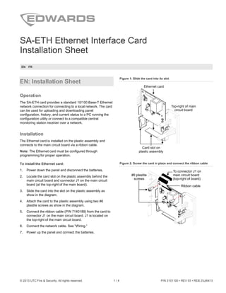
  • 1. © 2013 UTC Fire & Security. All rights reserved. 1 / 4 P/N 3101100 • REV 03 • REB 25JAN13 SA-ETH Ethernet Interface Card Installation Sheet EN FR EN: Installation Sheet Operation The SA-ETH card provides a standard 10/100 Base-T Ethernet network connection for connecting to a local network. The card can be used for uploading and downloading panel configuration, history, and current status to a PC running the configuration utility or connect to a compatible central monitoring station receiver over a network. Installation The Ethernet card is installed on the plastic assembly and connects to the main circuit board via a ribbon cable. Note: The Ethernet card must be configured through programming for proper operation. To install the Ethernet card: 1. Power down the panel and disconnect the batteries. 2. Locate the card slot on the plastic assembly behind the main circuit board and connector J1 on the main circuit board (at the top-right of the main board). 3. Slide the card into the slot on the plastic assembly as show in the diagram. 4. Attach the card to the plastic assembly using two #6 plastite screws as show in the diagram. 5. Connect the ribbon cable (P/N 7140189) from the card to connector J1 on the main circuit board. J1 is located on the top-right of the main circuit board. 6. Connect the network cable. See “Wiring.” 7. Power up the panel and connect the batteries. Figure 1: Slide the card into its slot Ethernet card Top-right of main circuit board Card slot on plastic assembly Figure 2: Screw the card in place and connect the ribbon cable To connector J1 on main circuit board (top-right of board) Ribbon cable #6 plastite screws
  • 2. 2 / 4 P/N 3101100 • REV 03 • REB 25JAN13 Wiring Note: A crossover cable or a straight through cable can be used. Figure 3: SA-ETH wiring Network cable Ethernet card To network connection (PC, router, switch, etc.) SA-ETH LEDs There are four LEDs on the card that indicate card and network status. Figure 4: LEDs Ethernet card LED 1 (DS1): Link LED 2 (DS2): Speed LED 3 (DS3): Duplex LED 4 (DS4): Collision SA-ETH compatibility The SA-ETH is listed for use with the following DACRs. Receiver Models Formats Osborne-Hoffman OH2000 and OH2000E (with a OH-TCP/IP-LC card installed) (see note below) Contact ID Note: If the line card firmware is V2.2 or later, use the default CMS network settings. If the line card firmware is V2.2 or earlier, the Timeout Seconds must be set to 60, the Hello Timer set to 75, and the Line Cut timer in the line card itself set to 175 seconds. If you are unsure of the firmware version in the receiver or there are communication faults between the panel and the receiver, then these settings are recommended. Specifications Ethernet 10/100 Base-T Connection mode Auto negotiation Operating voltage 24 VDC Operating current Standby/Alarm: 34 mA Max.: 41 mA Max. wire runs 200 feet (60 m), Cat 5 cable (panel to communication equipment) Cat 5 cable connector RJ-45 IP address (default) 192.168.001.003 Subnet mask (default) 255.255.255.0 Gateway (default) 000.000.000.000 Operating environment Temperature Humidity 32 to 120°F (0 to 49°C) 0 to 93% RH, noncondensing at 90°F (32°C) FR: Fiche D'Installation Fonctionnement La carte SA-ETH procure une connexion à un réseau Ethernet 10/100 à paire torsadée (Base-T) standard pour un branchement à un réseau local. La carte permet de télécharger en amont ou en aval la configuration, l’historique et l’état actuel du panneau de commande à un ordinateur exécutant l’utilitaire de configuration ou à se brancher à un récepteur d’une centrale de surveillance compatible au moyen d’un réseau. Installation La carte Ethernet est installée sur le montant en plastique et est branchée à la carte de circuits imprimés principale à l’aide d’un câble ruban. Remarque : Pour assurer un bon fonctionnement, la carte Ethernet doit être activée et configurée par programmation. Installation de la carte Ethernet : 1. Coupez l’alimentation au panneau et débranchez les piles. 2. Localisez la coche de la carte sur le montant en plastique derrière la carte de circuits imprimés et le connecteur J3 (coin supérieur droit de la carte de circuits imprimés principale). 3. Glissez la carte dans la coche du montant en plastique comme indiqué dans le diagramme. 4. Attachez la carte au montant en plastique à l’aide de deux vis plastie no 6 comme indiqué dans le diagramme.
  • 3. P/N 3101100 • REV 03 • REB 25JAN13 3 / 4 5. Branchez le câble ruban (P/N 7140189) de la carte au connecteur J1 de la carte de circuits imprimés principale. Le connecteur J1 est situé dans le coin supérieur droit de la carte de circuits imprimés. 6. Branchez le câble de réseau. Voir la section « Filage ». 7. Rétablissez l’alimentation au panneau et rebranchez les piles. Figure 1 : Glissez la carte dans la fente Carte Ethernet Coin droit de la carte de circuits supérieure imprimés Fentes de la carte du montage plastique Figure 2 : Vissez la carte en place et branchez le câble ruban Vis plastie n 6 o Au connecteur J1 sur carte de circuits oin supérieur droit) imprimés (c Câble ruban Filage Remarque : On peut utiliser un câble en croisé ou ininterrompu. Figure 3 : Filage du SA-ETH Câble de réseau Carte Ethernet À la connexion réseau (PC, routeur, commutateur, etc.) Voyants DEL de la SA-ETH Il y a quatre voyants DEL sur la carte qui indiquent l’état de la carte et du réseau. Figure 4 : Voyants DEL Carte Ethernet DEL 1 (lien) DEL 2 (vitesse) DEL 3 (duplex) DEL 4 (collision) Compatibilité de la SA-ETH Le SA-ETH est utilisable avec les DACR ci-dessous. Récepteur Modèles Formats Osborne-Hoffman OH2000 et OH2000E (avec une carte OH- TCP/IP-LC installée) (voir la remarque ci-dessous) Identification de contact Remarque : Si le micrologiciel de la carte de ligne est une version V2,2 ou antérieure, utilisez le réglage de réseau CMS par défaut. Si le micrologiciel de la carte de ligne est une version V2,2 ou plus récente, les secondes des temps morts doivent être réglées à 60, la minuterie Hello à 75 et la minuterie de coupure de ligne dans la carte elle-même à 175 secondes. Si vous n’êtes pas certain de la version du micrologiciel dans le récepteur ou qu’il y a des erreurs de communication entre le panneau de commande et le récepteur, on recommande des réglages.
  • 4. 4 / 4 P/N 3101100 • REV 03 • REB 25JAN13 Fiche technique Ethernet 10/100 Base-T Mode de connexion Négociation automatique Tension de service 24 VDC Courant opérationnel En attente et alarme : 34 mA Maximum : 41 mA Longueur maximale du filage 60 mètres (200 pi), câble de catégorie 5 (du panneau à l’équipement de communication) Connecteur de câble de catégorie 5 RJ-45 Adresse de protocole Internet (par défaut) 192.168.001.003 Filtre d’adresse locale (par défaut) 255.255.255.0 Passerelle (par défaut) 000.000.000.000 Environnement opérationnel Température Humidité 0 à 49 °C (32 à 120 °F) 0 à 93 % RH, non-condensation à 32 °C (90 °F)