
Recommended
Recommended
More Related Content
What's hot
What's hot (20)
Similar to Case M4K Forklift Truck Service Repair Manual
Similar to Case M4K Forklift Truck Service Repair Manual (12)
More from jksmemm ekmdm
More from jksmemm ekmdm (7)
Recently uploaded
Recently uploaded (20)
Case M4K Forklift Truck Service Repair Manual
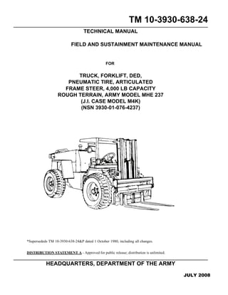
- 1. TM 10-3930-638-24 TECHNICAL MANUAL FIELD AND SUSTAINMENT MAINTENANCE MANUAL FOR TRUCK, FORKLIFT, DED, PNEUMATIC TIRE, ARTICULATED FRAME STEER, 4,000 LB CAPACITY ROUGH TERRAIN, ARMY MODEL MHE 237 (J.I. CASE MODEL M4K) (NSN 3930-01-076-4237) *Supersededs TM 10-3930-638-24&P dated 1 October 1980, including all changes. DISTRIBUTION STATEMENT A - Approved for public release; distribution is unlimited. HEADQUARTERS, DEPARTMENT OF THE ARMY JULY 2008
- 2. TM 10-3930-638-24 a WARNING SUMMARY This warning summary contains general safety warnings and hazardous materials warnings that must be understood and applied during operation and maintenance of this equipment. Failure to observe these warnings could result in serious injury or death to personnel. The following are explanations of safety and hazardous materials icons: BIOLOGICAL - abstract symbol bug shows that a material may contain bacteria or viruses that present a danger to life or health. CHEMICAL - drop of liquid on hand shows that the material will cause burns or irritation to human skin or tissue. EAR PROTECTION - headphones over ears show that noise level will harm ears. ELECTRICAL - electrical wire to arm with electricity symbol running through human body shows that shock hazard is present. EYE PROTECTION - person with goggles shows that the material will injure the eyes. FIRE - flame shows that a material may ignite and cause burns. FLYING PARTICLES - arrows bouncing off face with face shield shows that particles flying through the air will harm face. LIFTING HEAVY OBJECT - human figure stooping over heavy object shows physical injury potential from improper lifting technique.
- 3. TM 10-3930-638-24 b HEAVY PARTS - hand with heavy object on top shows that heavy parts can crush and harm. HEAVY PARTS - heavy object on human figure shows that heavy parts present a danger to life or limb. HEAVY PARTS - heavy object pinning human figure against wall shows that heavy, moving parts present a danger to life or limb. HOT AREA - hand over object radiating heat shows that part is hot and can burn. HYDRAULIC FLUID PRESSURE - hydraulic fluid spraying human hand shows that fluid escap- ing under great pressure can cause injury or death to personnel. RADIOACTIVE - identifies a material that emits radioactive energy and can injure human tissue or organs. SLICK FLOOR - wavy line on floor with legs prone shows that slick floor presents a danger from falling. VAPOR - human figure in a cloud shows that material vapors present a danger to life or health.
- 4. TM 10-3930-638-24 c FOR INFORMATION ON FIRST AID, REFER TO FM 4-25.11. • Carbon monoxide is a colorless, odorless, deadly poison which, when breathed, deprives the body of oxygen and causes suffocation. Exposure to air containing carbon monoxide produces symptoms of headache, dizzi- ness, loss of muscular control, apparent drowsiness, and coma. Permanent brain damage or death can result from severe exposure. • Carbon monoxide occurs in exhaust fumes of internal combustion engines. Carbon monoxide can become dan- gerously concentrated under conditions of inadequate ventilation. The following precautions must be observed to ensure safety of personnel when an internal combustion engine is operated. 1. DO NOT operate engine in enclosed areas. 2. DO NOT idle engine without adequate ventilation. 3. DO NOT operate engine with inspection plates or cover shields removed. 4. BE ALERT for exhaust poisoning symptoms. They are: • Headache • Dizziness • Sleepiness • Loss of muscular control 5. If you see another person with exhaust poisoning symptoms: • Remove person from area. • Expose to fresh air. • Keep person warm. • DO NOT permit physical exercise. • Administer Cardiopulmonary Resuscitation (CPR), if necessary. • Notify a medic. 6. BE AWARE. The field protective mask for Nuclear, Biological, and Chemical (NBC) protection will not protect you from carbon monoxide poisoning. The Best Defense Against Carbon Monoxide Poisoning Is Good Ventilation! WARNING CARBON MONOXIDE (EXHAUST GASES) CAN KILL!
- 5. TM 10-3930-638-24 d • To avoid injury, eye protection and acid-resistant gloves must be worn when working around batteries. DO NOT smoke, use open flame, make sparks, or create other ignition sources around batteries. If a battery is giv- ing off gases, it can explode and cause injury to personnel. Remove all jewelry such as rings, ID tags, watches, and bracelets. If jewelry or a tool contacts a battery terminal, a direct short will result in instant heating or elec- tric shock, damage to equipment, and injury to personnel. • Sulfuric acid contained in batteries can cause serious burns. If battery corrosion or electrolyte makes contact with skin, eyes or clothing, take immediate action to stop the corrosive burning effects. Failure to follow these procedures may result in death or serious injury to personnel. a. Eyes. Flush with cold water for no less than 15 minutes and seek medical attention immediately. b. Skin. Flush with large amounts of cold water until all acid is removed. Seek medical attention as required. c. Internal. If corrosion or electrolyte is ingested, drink large amounts of water or milk. Follow with milk of magnesia, beaten egg, or vegetable oil. Seek medical attention immediately. d. Clothing/Equipment. Wash area with large amounts of cold water. Neutralize acid with baking soda or household ammonia. Engine exhaust and some of its constituents, batteries and some of their constituents, and some dust created by power sanding, sawing, grinding, drilling, and other construction activities contain chemicals known to the State of California to cause cancer, birth defects, and other reproductive harm. Some examples of these chemicals are: • Lead from batteries, battery terminals, and posts. • Lead from lead-based paints. • Cement and other masonry products. • Arsenic and chromium from chemically treated lumber. Your risk from these exposures varies, depending on how often you do this type of work. To reduce expo- sure to these chemicals: • ALWAYS work in a well-ventilated area. • Work with approved safety equipment, such as gloves and dust masks that are specially designed to fil- ter out microscopic particles. WARNING BATTERIES WARNING CALIFORNIA - PROPOSITION 65
- 6. TM 10-3930-638-24 e Particles blown by compressed air are hazardous. DO NOT exceed 15 PSI (103 kPa) nozzle pressure when drying parts with compressed air. DO NOT exceed 30 PSI (207 kPa) nozzle pressure when cleaning parts with compressed air. DO NOT direct compressed air against human skin. Failure to follow this warning may result in injury to personnel. Make sure air stream is directed away from user and other personnel in the area. To prevent injury, user must wear protective goggles or face shield. Always disconnect battery ground cable before working on electrical components of this equipment. Failure to follow this warning may result in injury or death to personnel. NEVER crawl under equipment when performing maintenance unless equipment is blocked securely. Keep clear of equipment when it is raised or lowered. DO NOT allow heavy components to swing while sus- pended by lifting device. Exercise extreme caution when working near a cable or chain under tension. Fail- ure to follow this warning may result in injury or death to personnel. • DO NOT perform fuel system checks, inspections, or maintenance while smoking or near fire, flames, or sparks. Fuel may ignite, causing injury or death to personnel or damage to equipment. • Operating personnel must wear fuel-resistant gloves when handling fuels. If exposed to fuel, promptly wash exposed skin and change fuel-soaked clothing. Failure to follow this warning may result in injury to personnel. WARNING COMPRESSED AIR WARNING ELECTRICAL SHOCK HAZARD WARNING FALLING EQUIPMENT HAZARD WARNING FUEL HANDLING
- 7. TM 10-3930-638-24 f • When servicing this vehicle, performing maintenance, or disposing of materials such as engine coolant, hydraulic fluid, lubricants, battery acids or batteries, and CARC paint, consult your unit/local hazardous waste disposal center or safety office for local regulatory guidance. If further information is needed, please contact The Army Environmental Hotline at 1-800-872-3845. • Lubricating/hydraulic oils and engine coolant used in the performance of maintenance can be very slippery. Immediately wipe up any spills. Failure to follow this warning may result in injury to personnel. Your hearing can be PERMANENTLY DAMAGED if you are exposed to constant high noise levels of 85 dB or greater. Hearing protection is required when operating vehicle or when working on vehicle while it is operating. Failure to wear hearing protection may result in hearing loss. If NBC exposure is suspected, all air filter media should be handled by personnel wearing protective equip- ment. Consult your unit NBC Officer or NBC NCO for appropriate handling or disposal procedures. WARNING OPERATION OF VEHICLE • BE ALERT for personnel in the area while operating vehicle. Always check to ensure area is clear of personnel and obstructions before moving. Failure to follow this warning may result in injury or death to personnel. • Use of seat belt while operating vehicle is mandatory. Fasten belt BEFORE operating vehicle. Trying to fasten belt during operation creates a hazardous condition. Failure to follow this warning may result in injury or death to personnel. • DO NOT allow riders on vehicle. Failure to follow this warning may result in injury or death to personnel. • NEVER leave operator compartment without applying parking brake. Failure to follow this warning may result in injury or death to personnel. • DO NOT use parking/emergency brake to stop a moving vehicle under usual conditions. Only if service brakes fail, apply parking/emergency brake. Failure to follow this warning may result in injury to personnel or damage to equipment. WARNING HAZARDOUS WASTE DISPOSAL WARNING HEARING PROTECTION WARNING NBC EXPOSURE
- 8. TM 10-3930-638-24 g Use extreme caution when manually adjusting position of lifting forks. Avoid crushing fingers or hands by keeping hands away from pinch points. Failure to do so may result in serious injury. • DO NOT service cooling system unless engine has been allowed to cool down. This is a pressurized cooling system and escaping steam or hot coolant may result in serious burns. • DO NOT remove cooling system radiator cap when engine is hot. Allow engine to cool down. Loosen cap to first stop and let any pressure out of cooling system, then remove cap. Failure to follow this warning may result in serious burns. • Wear effective eye, hand, and skin protection when handling coolants. Failure to do so may result in injury to personnel. 2,500 PSI PRESSURE is used to operate this equipment. NEVER disconnect any hydraulic lines or fittings without checking manual to see how to drop the pressure to zero. Failure to follow this warning may result in injury or death to personnel. Solvent cleaning compound MIL-PRF-680 Type III is an environmentally compliant and low toxic material. However, it may be irritating to the eyes and skin. Use protective gloves and goggles. Use in well-ventilated areas. Keep away from open flames and other sources of ignition. Failure to do so may result in injury or death to personnel. WARNING PINCH POINTS WARNING PRESSURIZED COOLING SYSTEM WARNING PRESSURIZED HYDRAULIC SYSTEM WARNING SOLVENT CLEANING COMPOUND
- 9. TM 10-3930-638-24 h WARNING TIRES • Observe caution when inflating tires. Be sure tires are properly seated on rims before inflating. Failure to fol- low this warning may result in injury or death to personnel. Improperly seated tires can burst with explosive force sufficient to cause death. • Deflate tire completely before removing wheel from rim. Refer to manual to completely deflate tire. Failure to follow this warning may result in injury or death to personnel. • Lifting cables, chains, hooks, and slings used for lifting equipment must be in good condition and of suitable capacity. Failure to follow this warning may result in injury or death to personnel or damage to equipment. • Use extreme caution when handling heavy parts. Provide adequate support and use assistance during proce- dure. Ensure that any lifting device used is in good condition and of suitable load capacity. Keep clear of heavy parts supported only by lifting device. Failure to follow this warning may result in injury or death to personnel. • Hot oil or metal parts can cause severe burns. Wear insulated gloves, long sleeves, and eye protection when working with heated parts. WARNING WORK SAFETY
- 10. A TM 10-3930-638-24 LIST OF EFFECTIVE PAGES/WORK PACKAGES - NOTE: Zero in the “Change No.” column indicates and original page or work package. Date of issue for the original manual is: Original....15 July 2008 Total number of pages for front and rear matter is 38 and total number of work packages is 310, consisting of the following: Page/WP No. Change No. Page/WP No. Change No. Front Cover (2 pgs.) . . . . . . . . . . . . . . . . . . . 0 Warning Summary (8 pgs.). . . . . . . . . . . . . . 0 Table of Contents (12 pgs.). . . . . . . . . . . . . . 0 Chapter 1 title page WP 0001 (2 pgs.) . . . . . . . . . . . . . . . . . . . . . 0 WP 0002 (10 pgs.) . . . . . . . . . . . . . . . . . . . . 0 WP 0003 (8 pgs.) . . . . . . . . . . . . . . . . . . . . . 0 Chapter 2 title page WP 0004 (2 pgs.) . . . . . . . . . . . . . . . . . . . . . 0 WP 0005 (4 pgs.) . . . . . . . . . . . . . . . . . . . . . 0 WP 0006 (14 pgs.) . . . . . . . . . . . . . . . . . . . . 0 WP 0007 (4 pgs.) . . . . . . . . . . . . . . . . . . . . . 0 WP 0008 (2 pgs.) . . . . . . . . . . . . . . . . . . . . . 0 WP 0009 (2 pgs.) . . . . . . . . . . . . . . . . . . . . . 0 WP 0010 (2 pgs.) . . . . . . . . . . . . . . . . . . . . . 0 WP 0011 (2 pgs.) . . . . . . . . . . . . . . . . . . . . . 0 WP 0012 (4 pgs.) . . . . . . . . . . . . . . . . . . . . . 0 WP 0013 (2 pgs.) . . . . . . . . . . . . . . . . . . . . . 0 WP 0014 (2 pgs.) . . . . . . . . . . . . . . . . . . . . . 0 WP 0015 (2 pgs.) . . . . . . . . . . . . . . . . . . . . . 0 WP 0016 (2 pgs.) . . . . . . . . . . . . . . . . . . . . . 0 WP 0017 (8 pgs.) . . . . . . . . . . . . . . . . . . . . . 0 WP 0018 (2 pgs.) . . . . . . . . . . . . . . . . . . . . . 0 WP 0019 (4 pgs.) . . . . . . . . . . . . . . . . . . . . . 0 WP 0020 (2 pgs.) . . . . . . . . . . . . . . . . . . . . . 0 WP 0021 (10 pgs.) . . . . . . . . . . . . . . . . . . . . 0 WP 0022 (2 pgs.) . . . . . . . . . . . . . . . . . . . . . 0 WP 0023 (4 pgs.) . . . . . . . . . . . . . . . . . . . . . 0 WP 0024 (2 pgs.) . . . . . . . . . . . . . . . . . . . . . 0 WP 0025 (2 pgs.) . . . . . . . . . . . . . . . . . . . . . 0 WP 0026 (4 pgs.) . . . . . . . . . . . . . . . . . . . . . 0 WP 0027 (2 pgs.) . . . . . . . . . . . . . . . . . . . . . 0 Chapter 3 title page WP 0028 (2 pgs.) . . . . . . . . . . . . . . . . . . . . . 0 WP 0029 (4 pgs.) . . . . . . . . . . . . . . . . . . . . . 0 WP 0030 (6 pgs.) . . . . . . . . . . . . . . . . . . . . . 0 WP 0031 (6 pgs.) . . . . . . . . . . . . . . . . . . . . . 0 WP 0032 (16 pgs.) . . . . . . . . . . . . . . . . . . . . 0 WP 0033 (4 pgs.) . . . . . . . . . . . . . . . . . . . . . 0 WP 0034 (4 pgs.) . . . . . . . . . . . . . . . . . . . . . 0 WP 0035 (2 pgs.) . . . . . . . . . . . . . . . . . . . . . 0 WP 0036 (2 pgs.) . . . . . . . . . . . . . . . . . . . . . 0 WP 0037 (2 pgs.) . . . . . . . . . . . . . . . . . . . . . 0 WP 0038 (2 pgs.) . . . . . . . . . . . . . . . . . . . . . 0 WP 0039 (2 pgs.) . . . . . . . . . . . . . . . . . . . . . 0 WP 0040 (2 pgs.) . . . . . . . . . . . . . . . . . . . . . 0 WP 0041 (4 pgs.) . . . . . . . . . . . . . . . . . . . . . 0 WP 0042 (2 pgs.) . . . . . . . . . . . . . . . . . . . . . 0 WP 0043 (12 pgs.) . . . . . . . . . . . . . . . . . . . . 0 Chapter 4 title page WP 0044 (4 pgs.) . . . . . . . . . . . . . . . . . . . . . 0 WP 0045 (4 pgs.) . . . . . . . . . . . . . . . . . . . . . 0 WP 0046 (4 pgs.) . . . . . . . . . . . . . . . . . . . . . 0 WP 0047 (2 pgs.) . . . . . . . . . . . . . . . . . . . . . 0 WP 0048 (2 pgs.) . . . . . . . . . . . . . . . . . . . . . 0 WP 0049 (2 pgs.) . . . . . . . . . . . . . . . . . . . . . 0 WP 0050 (2 pgs.) . . . . . . . . . . . . . . . . . . . . . 0 WP 0051 (2 pgs.) . . . . . . . . . . . . . . . . . . . . . 0 WP 0052 (2 pgs.) . . . . . . . . . . . . . . . . . . . . . 0 WP 0053 (6 pgs.) . . . . . . . . . . . . . . . . . . . . . 0 WP 0054 (4 pgs.) . . . . . . . . . . . . . . . . . . . . . 0 WP 0055 (6 pgs.) . . . . . . . . . . . . . . . . . . . . . 0 WP 0056 (4 pgs.) . . . . . . . . . . . . . . . . . . . . . 0 WP 0057 (2 pgs.) . . . . . . . . . . . . . . . . . . . . . 0 WP 0058 (2 pgs.) . . . . . . . . . . . . . . . . . . . . . 0 WP 0059 (6 pgs.) . . . . . . . . . . . . . . . . . . . . . 0 WP 0060 (6 pgs.) . . . . . . . . . . . . . . . . . . . . . 0 WP 0061 (6 pgs.) . . . . . . . . . . . . . . . . . . . . . 0 WP 0062 (6 pgs.) . . . . . . . . . . . . . . . . . . . . . 0 WP 0063 (4 pgs.) . . . . . . . . . . . . . . . . . . . . . 0 WP 0064 (4 pgs.) . . . . . . . . . . . . . . . . . . . . . 0 WP 0065 (4 pgs.) . . . . . . . . . . . . . . . . . . . . . 0
- 11. B TM 10-3930-638-24 Page/WP No. Change No. Page/WP No. Change No. WP 0066 (4 pgs.) . . . . . . . . . . . . . . . . . . . . . 0 WP 0067 (2 pgs.) . . . . . . . . . . . . . . . . . . . . . 0 WP 0068 (2 pgs.) . . . . . . . . . . . . . . . . . . . . . 0 WP 0069 (6 pgs.) . . . . . . . . . . . . . . . . . . . . . 0 WP 0070 (4 pgs.) . . . . . . . . . . . . . . . . . . . . . 0 WP 0071 (4 pgs.) . . . . . . . . . . . . . . . . . . . . . 0 WP 0072 (4 pgs.) . . . . . . . . . . . . . . . . . . . . . 0 WP 0073 (4 pgs.) . . . . . . . . . . . . . . . . . . . . . 0 WP 0074 (6 pgs.) . . . . . . . . . . . . . . . . . . . . . 0 WP 0075 (8 pgs.) . . . . . . . . . . . . . . . . . . . . . 0 WP 0076 (8 pgs.) . . . . . . . . . . . . . . . . . . . . . 0 WP 0077 (6 pgs.) . . . . . . . . . . . . . . . . . . . . . 0 WP 0078 (4 pgs.) . . . . . . . . . . . . . . . . . . . . . 0 WP 0079 (4 pgs.) . . . . . . . . . . . . . . . . . . . . . 0 WP 0080 (2 pgs.) . . . . . . . . . . . . . . . . . . . . . 0 WP 0081 (4 pgs.) . . . . . . . . . . . . . . . . . . . . . 0 WP 0082 (8 pgs.) . . . . . . . . . . . . . . . . . . . . . 0 WP 0083 (6 pgs.) . . . . . . . . . . . . . . . . . . . . . 0 WP 0084 (4 pgs.) . . . . . . . . . . . . . . . . . . . . . 0 WP 0085 (4 pgs.) . . . . . . . . . . . . . . . . . . . . . 0 WP 0086 (4 pgs.) . . . . . . . . . . . . . . . . . . . . . 0 WP 0087 (2 pgs.) . . . . . . . . . . . . . . . . . . . . . 0 WP 0088 (4 pgs.) . . . . . . . . . . . . . . . . . . . . . 0 WP 0089 (4 pgs.) . . . . . . . . . . . . . . . . . . . . . 0 WP 0090 (2 pgs.) . . . . . . . . . . . . . . . . . . . . . 0 WP 0091 (4 pgs.) . . . . . . . . . . . . . . . . . . . . . 0 WP 0092 (4 pgs.) . . . . . . . . . . . . . . . . . . . . . 0 WP 0093 (6 pgs.) . . . . . . . . . . . . . . . . . . . . . 0 WP 0094 (6 pgs.) . . . . . . . . . . . . . . . . . . . . . 0 WP 0095 (6 pgs.) . . . . . . . . . . . . . . . . . . . . . 0 WP 0096 (4 pgs.) . . . . . . . . . . . . . . . . . . . . . 0 WP 0097 (4 pgs.) . . . . . . . . . . . . . . . . . . . . . 0 WP 0098 (6 pgs.) . . . . . . . . . . . . . . . . . . . . . 0 WP 0099 (2 pgs.) . . . . . . . . . . . . . . . . . . . . . 0 WP 0100 (4 pgs.) . . . . . . . . . . . . . . . . . . . . . 0 (4 pgs.) . . . . . . . . . . . . . . . . . . . . . . . . . . . . . 0 WP 0101 (4 pgs.) . . . . . . . . . . . . . . . . . . . . . 0 WP 0102 (4 pgs.) . . . . . . . . . . . . . . . . . . . . . 0 WP 0103 (4 pgs.) . . . . . . . . . . . . . . . . . . . . . 0 WP 0104 (4 pgs.) . . . . . . . . . . . . . . . . . . . . . 0 WP 0105 (4 pgs.) . . . . . . . . . . . . . . . . . . . . . 0 WP 0106 (4 pgs.) . . . . . . . . . . . . . . . . . . . . . .0 WP 0107 (4 pgs.) . . . . . . . . . . . . . . . . . . . . . .0 WP 0108 (4 pgs.) . . . . . . . . . . . . . . . . . . . . . .0 WP 0109 (4 pgs.) . . . . . . . . . . . . . . . . . . . . . .0 WP 0110 (4 pgs.) . . . . . . . . . . . . . . . . . . . . . .0 WP 0111 (6 pgs.) . . . . . . . . . . . . . . . . . . . . . .0 WP 0112 (4 pgs.) . . . . . . . . . . . . . . . . . . . . . .0 WP 0113 (6 pgs.) . . . . . . . . . . . . . . . . . . . . . .0 WP 0114 (6 pgs.) . . . . . . . . . . . . . . . . . . . . . .0 WP 0115 (4 pgs.) . . . . . . . . . . . . . . . . . . . . . .0 WP 0116 (4 pgs.) . . . . . . . . . . . . . . . . . . . . . .0 WP 0117 (4 pgs.) . . . . . . . . . . . . . . . . . . . . . .0 WP 0118 (4 pgs.) . . . . . . . . . . . . . . . . . . . . . .0 WP 0119 (4 pgs.) . . . . . . . . . . . . . . . . . . . . . .0 WP 0120 (4 pgs.) . . . . . . . . . . . . . . . . . . . . . .0 WP 0121 (4 pgs.) . . . . . . . . . . . . . . . . . . . . . .0 WP 0122 (6 pgs.) . . . . . . . . . . . . . . . . . . . . . .0 WP 0123 (4 pgs.) . . . . . . . . . . . . . . . . . . . . . .0 WP 0124 (4 pgs.) . . . . . . . . . . . . . . . . . . . . . .0 WP 0125 (4 pgs.) . . . . . . . . . . . . . . . . . . . . . .0 WP 0126 (2 pgs.) . . . . . . . . . . . . . . . . . . . . . .0 WP 0127 (4 pgs.) . . . . . . . . . . . . . . . . . . . . . .0 WP 0128 (4 pgs.) . . . . . . . . . . . . . . . . . . . . . .0 WP 0129 (4 pgs.) . . . . . . . . . . . . . . . . . . . . . .0 WP 0130 (4 pgs.) . . . . . . . . . . . . . . . . . . . . . .0 WP 0131 (4 pgs.) . . . . . . . . . . . . . . . . . . . . . .0 WP 0132 (4 pgs.) . . . . . . . . . . . . . . . . . . . . . .0 WP 0133 (6 pgs.) . . . . . . . . . . . . . . . . . . . . . .0 WP 0134 (6 pgs.) . . . . . . . . . . . . . . . . . . . . . .0 WP 0135 (4 pgs.) . . . . . . . . . . . . . . . . . . . . . .0 WP 0136 (4 pgs.) . . . . . . . . . . . . . . . . . . . . . .0 WP 0137 (4 pgs.) . . . . . . . . . . . . . . . . . . . . . .0 WP 0138 (4 pgs.) . . . . . . . . . . . . . . . . . . . . . .0 WP 0139 (4 pgs.) . . . . . . . . . . . . . . . . . . . . . .0 WP 0140 (4 pgs.) . . . . . . . . . . . . . . . . . . . . . .0 WP 0141 (4 pgs.) . . . . . . . . . . . . . . . . . . . . . .0 WP 0142 (4 pgs.) . . . . . . . . . . . . . . . . . . . . . .0 WP 0143 (4 pgs.) . . . . . . . . . . . . . . . . . . . . . .0 WP 0144 (4 pgs.) . . . . . . . . . . . . . . . . . . . . . .0 WP 0145 (4 pgs.) . . . . . . . . . . . . . . . . . . . . . .0 WP 0146 (2 pgs.) . . . . . . . . . . . . . . . . . . . . . .0 WP 0147 (6 pgs.) . . . . . . . . . . . . . . . . . . . . . .0 WP 0148 (16 pgs.) . . . . . . . . . . . . . . . . . . . . .0
- 12. C TM 10-3930-638-24 Page/WP No. Change No. Page/WP No. Change No. WP 0149 (6 pgs.). . . . . . . . . . . . . . . . . . . . . . 0 WP 0150 (4 pgs.). . . . . . . . . . . . . . . . . . . . . . 0 WP 0151 (2 pgs.). . . . . . . . . . . . . . . . . . . . . . 0 WP 0152 (6 pgs.). . . . . . . . . . . . . . . . . . . . . . 0 WP 0153 (2 pgs.). . . . . . . . . . . . . . . . . . . . . . 0 WP 0154 (6 pgs.). . . . . . . . . . . . . . . . . . . . . . 0 WP 0155 (6 pgs.). . . . . . . . . . . . . . . . . . . . . . 0 WP 0156 (6 pgs.). . . . . . . . . . . . . . . . . . . . . . 0 WP 0157 (4 pgs.). . . . . . . . . . . . . . . . . . . . . . 0 WP 0158 (2 pgs.). . . . . . . . . . . . . . . . . . . . . . 0 WP 0159 (2 pgs.). . . . . . . . . . . . . . . . . . . . . . 0 WP 0160 (8 pgs.). . . . . . . . . . . . . . . . . . . . . . 0 WP 0161 (6 pgs.). . . . . . . . . . . . . . . . . . . . . . 0 WP 0162 (8 pgs.). . . . . . . . . . . . . . . . . . . . . . 0 WP 0163 (8 pgs.). . . . . . . . . . . . . . . . . . . . . . 0 WP 0164 (6 pgs.). . . . . . . . . . . . . . . . . . . . . . 0 WP 0165 (6 pgs.). . . . . . . . . . . . . . . . . . . . . . 0 WP 0166 (10 pgs.). . . . . . . . . . . . . . . . . . . . . 0 WP 0167 (6 pgs.). . . . . . . . . . . . . . . . . . . . . . 0 WP 0168 (6 pgs.). . . . . . . . . . . . . . . . . . . . . . 0 WP 0169 (4 pgs.). . . . . . . . . . . . . . . . . . . . . . 0 WP 0170 (4 pgs.). . . . . . . . . . . . . . . . . . . . . . 0 WP 0171 (6 pgs.). . . . . . . . . . . . . . . . . . . . . . 0 WP 0172 (8 pgs.). . . . . . . . . . . . . . . . . . . . . . 0 WP 0173 (4 pgs.). . . . . . . . . . . . . . . . . . . . . . 0 WP 0174 (4 pgs.). . . . . . . . . . . . . . . . . . . . . . 0 WP 0175 (2 pgs.). . . . . . . . . . . . . . . . . . . . . . 0 WP 0176 (4 pgs.). . . . . . . . . . . . . . . . . . . . . . 0 WP 0177 (6 pgs.). . . . . . . . . . . . . . . . . . . . . . 0 WP 0178 (6 pgs.). . . . . . . . . . . . . . . . . . . . . . 0 WP 0179 (4 pgs.). . . . . . . . . . . . . . . . . . . . . . 0 WP 0180 (4 pgs.). . . . . . . . . . . . . . . . . . . . . . 0 WP 0181 (4 pgs.). . . . . . . . . . . . . . . . . . . . . . 0 WP 0182 (4 pgs.). . . . . . . . . . . . . . . . . . . . . . 0 WP 0183 (4 pgs.). . . . . . . . . . . . . . . . . . . . . . 0 WP 0184 (6 pgs.). . . . . . . . . . . . . . . . . . . . . . 0 WP 0185 (6 pgs.). . . . . . . . . . . . . . . . . . . . . . 0 WP 0186 (4 pgs.). . . . . . . . . . . . . . . . . . . . . . 0 WP 0187 (4 pgs.). . . . . . . . . . . . . . . . . . . . . . 0 WP 0188 (4 pgs.). . . . . . . . . . . . . . . . . . . . . . 0 WP 0189 (2 pgs.). . . . . . . . . . . . . . . . . . . . . . 0 WP 0190 (4 pgs.). . . . . . . . . . . . . . . . . . . . . . 0 WP 0191 (4 pgs.). . . . . . . . . . . . . . . . . . . . . . 0 WP 0192 (4 pgs.) . . . . . . . . . . . . . . . . . . . . . 0 WP 0193 (10 pgs.) . . . . . . . . . . . . . . . . . . . . 0 WP 0194 (8 pgs.) . . . . . . . . . . . . . . . . . . . . . 0 WP 0195 (10 pgs.) . . . . . . . . . . . . . . . . . . . . 0 WP 0196 (10 pgs.) . . . . . . . . . . . . . . . . . . . . 0 WP 0197 (12 pgs.) . . . . . . . . . . . . . . . . . . . . 0 WP 0198 (4 pgs.) . . . . . . . . . . . . . . . . . . . . . 0 WP 0199 (4 pgs.) . . . . . . . . . . . . . . . . . . . . . 0 WP 0200 (4 pgs.) . . . . . . . . . . . . . . . . . . . . . 0 WP 0201 (6 pgs.) . . . . . . . . . . . . . . . . . . . . . 0 WP 0202 (2 pgs.) . . . . . . . . . . . . . . . . . . . . . 0 WP 0203 (2 pgs.) . . . . . . . . . . . . . . . . . . . . . 0 Chapter 5 title page WP 0204 (6 pgs.) . . . . . . . . . . . . . . . . . . . . . 0 WP 0205 (2 pgs.) . . . . . . . . . . . . . . . . . . . . . 0 WP 0206 (4 pgs.) . . . . . . . . . . . . . . . . . . . . . 0 WP 0207 (2 pgs.) . . . . . . . . . . . . . . . . . . . . . 0 WP 0208 (6 pgs.) . . . . . . . . . . . . . . . . . . . . . 0 WP 0209 (6 pgs.) . . . . . . . . . . . . . . . . . . . . . 0 WP 0210 (4 pgs.) . . . . . . . . . . . . . . . . . . . . . 0 WP 0211 (6 pgs.) . . . . . . . . . . . . . . . . . . . . . 0 WP 0212 (2 pgs.) . . . . . . . . . . . . . . . . . . . . . 0 WP 0213 (4 pgs.) . . . . . . . . . . . . . . . . . . . . . 0 WP 0214 (6 pgs.) . . . . . . . . . . . . . . . . . . . . . 0 WP 0215 (2 pgs.) . . . . . . . . . . . . . . . . . . . . . 0 WP 0216 (2 pgs.) . . . . . . . . . . . . . . . . . . . . . 0 WP 0217 (4 pgs.) . . . . . . . . . . . . . . . . . . . . . 0 WP 0218 (6 pgs.) . . . . . . . . . . . . . . . . . . . . . 0 WP 0219 (4 pgs.) . . . . . . . . . . . . . . . . . . . . . 0 WP 0220 (2 pgs.) . . . . . . . . . . . . . . . . . . . . . 0 WP 0221 (2 pgs.) . . . . . . . . . . . . . . . . . . . . . 0 WP 0222 (4 pgs.) . . . . . . . . . . . . . . . . . . . . . 0 WP 0223 (4 pgs.) . . . . . . . . . . . . . . . . . . . . . 0 WP 0224 (8 pgs.) . . . . . . . . . . . . . . . . . . . . . 0 WP 0225 (6 pgs.) . . . . . . . . . . . . . . . . . . . . . 0 WP 0226 (4 pgs.) . . . . . . . . . . . . . . . . . . . . . 0 WP 0227 (6 pgs.) . . . . . . . . . . . . . . . . . . . . . 0 WP 0228 (4 pgs.) . . . . . . . . . . . . . . . . . . . . . 0 WP 0229 (6 pgs.) . . . . . . . . . . . . . . . . . . . . . 0 WP 0230 (6 pgs.) . . . . . . . . . . . . . . . . . . . . . 0 WP 0231 (4 pgs.) . . . . . . . . . . . . . . . . . . . . . 0 WP 0232 (4 pgs.) . . . . . . . . . . . . . . . . . . . . . 0 WP 0233 (10 pgs.) . . . . . . . . . . . . . . . . . . . . 0
- 13. D TM 10-3930-638-24 Page/WP No. Change No. Page/WP No. Change No. WP 0234 (8 pgs.) . . . . . . . . . . . . . . . . . . . . . 0 WP 0235 (2 pgs.) . . . . . . . . . . . . . . . . . . . . . 0 WP 0236 (2 pgs.) . . . . . . . . . . . . . . . . . . . . . 0 WP 0237 (12 pgs.) . . . . . . . . . . . . . . . . . . . . 0 WP 0238 (14 pgs.) . . . . . . . . . . . . . . . . . . . . 0 WP 0239 (4 pgs.) . . . . . . . . . . . . . . . . . . . . . 0 WP 0240 (4 pgs.) . . . . . . . . . . . . . . . . . . . . . 0 WP 0241 (4 pgs.) . . . . . . . . . . . . . . . . . . . . . 0 WP 0242 (4 pgs.) . . . . . . . . . . . . . . . . . . . . . 0 WP 0243 (4 pgs.) . . . . . . . . . . . . . . . . . . . . . 0 WP 0244 (2 pgs.) . . . . . . . . . . . . . . . . . . . . . 0 WP 0245 (2 pgs.) . . . . . . . . . . . . . . . . . . . . . 0 WP 0246 (2 pgs.) . . . . . . . . . . . . . . . . . . . . . 0 WP 0247 (2 pgs.) . . . . . . . . . . . . . . . . . . . . . 0 WP 0248 (4 pgs.) . . . . . . . . . . . . . . . . . . . . . 0 WP 0249 (4 pgs.) . . . . . . . . . . . . . . . . . . . . . 0 WP 0250 (4 pgs.) . . . . . . . . . . . . . . . . . . . . . 0 WP 0251 (4 pgs.) . . . . . . . . . . . . . . . . . . . . . 0 WP 0252 (2 pgs.) . . . . . . . . . . . . . . . . . . . . . 0 WP 0253 (2 pgs.) . . . . . . . . . . . . . . . . . . . . . 0 WP 0254 (2 pgs.) . . . . . . . . . . . . . . . . . . . . . 0 WP 0255 (6 pgs.) . . . . . . . . . . . . . . . . . . . . . 0 WP 0256 (6 pgs.) . . . . . . . . . . . . . . . . . . . . . 0 WP 0257 (6 pgs.) . . . . . . . . . . . . . . . . . . . . . 0 WP 0258 (22 pgs.) . . . . . . . . . . . . . . . . . . . . 0 WP 0259 (8 pgs.) . . . . . . . . . . . . . . . . . . . . . 0 WP 0260 (6 pgs.) . . . . . . . . . . . . . . . . . . . . . 0 WP 0261 (6 pgs.) . . . . . . . . . . . . . . . . . . . . . 0 WP 0262 (16 pgs.) . . . . . . . . . . . . . . . . . . . . 0 WP 0263 (10 pgs.) . . . . . . . . . . . . . . . . . . . . 0 WP 0264 (10 pgs.) . . . . . . . . . . . . . . . . . . . . 0 WP 0265 (10 pgs.) . . . . . . . . . . . . . . . . . . . . 0 WP 0266 (16 pgs.) . . . . . . . . . . . . . . . . . . . . 0 WP 0267 (4 pgs.) . . . . . . . . . . . . . . . . . . . . . 0 WP 0268 (10 pgs.) . . . . . . . . . . . . . . . . . . . . 0 WP 0269 (6 pgs.) . . . . . . . . . . . . . . . . . . . . . 0 Chapter 6 title page WP 0270 (8 pgs.) . . . . . . . . . . . . . . . . . . . . . 0 WP 0271 (8 pgs.) . . . . . . . . . . . . . . . . . . . . . 0 WP 0272 (14 pgs.) . . . . . . . . . . . . . . . . . . . . 0 WP 0273 (14 pgs.) . . . . . . . . . . . . . . . . . . . . .0 WP 0274 (4 pgs.) . . . . . . . . . . . . . . . . . . . . . .0 WP 0275 (4 pgs.) . . . . . . . . . . . . . . . . . . . . . .0 WP 0276 (12 pgs.) . . . . . . . . . . . . . . . . . . . . .0 WP 0277 (10 pgs.) . . . . . . . . . . . . . . . . . . . . .0 WP 0278 (6 pgs.) . . . . . . . . . . . . . . . . . . . . . .0 WP 0279 (6 pgs.) . . . . . . . . . . . . . . . . . . . . . .0 WP 0280 (10 pgs.) . . . . . . . . . . . . . . . . . . . . .0 WP 0281 (16 pgs.) . . . . . . . . . . . . . . . . . . . . .0 WP 0282 (10 pgs.) . . . . . . . . . . . . . . . . . . . . .0 WP 0283 (12 pgs.) . . . . . . . . . . . . . . . . . . . . .0 WP 0284 (10 pgs.) . . . . . . . . . . . . . . . . . . . . .0 WP 0285 (4 pgs.) . . . . . . . . . . . . . . . . . . . . . .0 WP 0286 (6 pgs.) . . . . . . . . . . . . . . . . . . . . . .0 WP 0287 (4 pgs.) . . . . . . . . . . . . . . . . . . . . . .0 WP 0288 (12 pgs.) . . . . . . . . . . . . . . . . . . . . .0 WP 0289 (50 pgs.) . . . . . . . . . . . . . . . . . . . . .0 WP 0290 (12 pgs.) . . . . . . . . . . . . . . . . . . . . .0 WP 0291 (6 pgs.) . . . . . . . . . . . . . . . . . . . . . .0 WP 0292 (6 pgs.) . . . . . . . . . . . . . . . . . . . . . .0 WP 0293 (12 pgs.) . . . . . . . . . . . . . . . . . . . . .0 WP 0294 (8 pgs.) . . . . . . . . . . . . . . . . . . . . . .0 WP 0295 (10 pgs.) . . . . . . . . . . . . . . . . . . . . .0 WP 0296 (6 pgs.) . . . . . . . . . . . . . . . . . . . . . .0 WP 0297 (6 pgs.) . . . . . . . . . . . . . . . . . . . . . .0 WP 0298 (4 pgs.) . . . . . . . . . . . . . . . . . . . . . .0 WP 0299 (6 pgs.) . . . . . . . . . . . . . . . . . . . . . .0 WP 0300 (8 pgs.) . . . . . . . . . . . . . . . . . . . . . .0 WP 0301 (4 pgs.) . . . . . . . . . . . . . . . . . . . . . .0 WP 0302 (4 pgs.) . . . . . . . . . . . . . . . . . . . . . .0 WP 0303 (4 pgs.) . . . . . . . . . . . . . . . . . . . . . .0 WP 0304 (2 pgs.) . . . . . . . . . . . . . . . . . . . . . .0 WP 0305 (2 pgs.) . . . . . . . . . . . . . . . . . . . . . .0 WP 0306 (18 pgs.) . . . . . . . . . . . . . . . . . . . . .0 Chapter 7 title page WP 0307 (2 pgs.) . . . . . . . . . . . . . . . . . . . . . .0 WP 0308 (4 pgs.) . . . . . . . . . . . . . . . . . . . . . .0 WP 0309 (16 pgs.) . . . . . . . . . . . . . . . . . . . . .0 WP 0310 (6 pgs.) . . . . . . . . . . . . . . . . . . . . . .0 Index (14 pgs.) . . . . . . . . . . . . . . . . . . . . . . . .0 Back Cover (2 pgs.) . . . . . . . . . . . . . . . . . . . .0
- 14. *TM 10-3930-638-24 i TECHNICAL MANUAL HEADQUARTERS TM 10-3930-638-24 DEPARTMENT OF THE ARMY Washington, D.C., 15 July 2008 TECHNICAL MANUAL FIELD MAINTENANCE MANUAL (Includes Unit and Direct Support Maintenance) FOR TRUCK, FORKLIFT, DED, PNEUMATIC TIRE, ARTICULATED FRAME STEER, 4,000 LB. CAPACITY ROUGH TERRAIN, ARMY MODEL MHE 237 (J.I. CASE MODEL M4K) (NSN 3930-01-076-4237)) *Supersedes TM 10-3930-638-24&P dated 1 October 1980, including all changes. DISTRIBUTION STATEMENT A - Approved for public release; distribution is unlimited. TABLE OF CONTENTS - - Warning Summary. . . . . . . . . . . . . . . . . . . . . . . . . . . . . . . . . . . . . . . . . . . . . . . . . . . . . . . . . . . . . . . . . . . . . . . a How to Use This Manual . . . . . . . . . . . . . . . . . . . . . . . . . . . . . . . . . . . . . . . . . . . . . . . . . . . . . . . . . . . . . . . . . . xi Chapter 1 - INTRODUCTORY INFORMATION, EQUIPMENT DESCRIPTION AND DATA, AND THEORY OF OPERATION Introductory Information. . . . . . . . . . . . . . . . . . . . . . . . . . . . . . . . . . . . . . . . . . . . . . . . . . . . . . . . . . . . .WP 0001 Equipment Description and Data. . . . . . . . . . . . . . . . . . . . . . . . . . . . . . . . . . . . . . . . . . . . . . . . . . . . . .WP 0002 Theory of Operation. . . . . . . . . . . . . . . . . . . . . . . . . . . . . . . . . . . . . . . . . . . . . . . . . . . . . . . . . . . . . . . .WP 0003 Chapter 2 - ORGANIZATIONAL TROUBLESHOOTING PROCEDURES Organizational Troubleshooting Procedures Introduction . . . . . . . . . . . . . . . . . . . . . . . . . . . . . . . . . . .WP 0004 Organizational Troubleshooting Symptom Index. . . . . . . . . . . . . . . . . . . . . . . . . . . . . . . . . . . . . . . . . .WP 0005 Engine Troubleshooting. . . . . . . . . . . . . . . . . . . . . . . . . . . . . . . . . . . . . . . . . . . . . . . . . . . . . . . . . . . . .WP 0006 REPORTING ERRORS AND RECOMMENDING IMPROVEMENTS
- 15. ii TM 10-3930-638-24 TABLE OF CONTENTS - CONTINUED - WP Sequence No.- Fuel System Troubleshooting . . . . . . . . . . . . . . . . . . . . . . . . . . . . . . . . . . . . . . . . . . . . . . . . . . . . . . . . WP 0007 Exhaust System Troubleshooting . . . . . . . . . . . . . . . . . . . . . . . . . . . . . . . . . . . . . . . . . . . . . . . . . . . . . WP 0008 Cooling System Troubleshooting . . . . . . . . . . . . . . . . . . . . . . . . . . . . . . . . . . . . . . . . . . . . . . . . . . . . . WP 0009 Battery System Troubleshooting (Model 207) . . . . . . . . . . . . . . . . . . . . . . . . . . . . . . . . . . . . . . . . . . . WP 0010 Battery System Troubleshooting (Model 4-390) . . . . . . . . . . . . . . . . . . . . . . . . . . . . . . . . . . . . . . . . . . WP 0011 Starting System Troubleshooting (Model 207) . . . . . . . . . . . . . . . . . . . . . . . . . . . . . . . . . . . . . . . . . . . WP 0012 Starting System Troubleshooting (Model 4-390) . . . . . . . . . . . . . . . . . . . . . . . . . . . . . . . . . . . . . . . . . WP 0013 Charging System Troubleshooting (Model 207) . . . . . . . . . . . . . . . . . . . . . . . . . . . . . . . . . . . . . . . . . . WP 0014 Charging System Troubleshooting (Model 4-390) . . . . . . . . . . . . . . . . . . . . . . . . . . . . . . . . . . . . . . . . WP 0015 Horn and Back-Up Alarm System Troubleshooting . . . . . . . . . . . . . . . . . . . . . . . . . . . . . . . . . . . . . . . WP 0016 Light Systems Troubleshooting . . . . . . . . . . . . . . . . . . . . . . . . . . . . . . . . . . . . . . . . . . . . . . . . . . . . . . WP 0017 Instrument Panel Troubleshooting . . . . . . . . . . . . . . . . . . . . . . . . . . . . . . . . . . . . . . . . . . . . . . . . . . . . WP 0018 Transmission Troubleshooting . . . . . . . . . . . . . . . . . . . . . . . . . . . . . . . . . . . . . . . . . . . . . . . . . . . . . . . WP 0019 Axles and Drive Shaft Assemblies Troubleshooting . . . . . . . . . . . . . . . . . . . . . . . . . . . . . . . . . . . . . . . WP 0020 Brake System Troubleshooting . . . . . . . . . . . . . . . . . . . . . . . . . . . . . . . . . . . . . . . . . . . . . . . . . . . . . . WP 0021 Wheels and Tires Troubleshooting . . . . . . . . . . . . . . . . . . . . . . . . . . . . . . . . . . . . . . . . . . . . . . . . . . . . WP 0022 Steering System Troubleshooting . . . . . . . . . . . . . . . . . . . . . . . . . . . . . . . . . . . . . . . . . . . . . . . . . . . . . WP 0023 Frame and Towing Attachments Troubleshooting. . . . . . . . . . . . . . . . . . . . . . . . . . . . . . . . . . . . . . . . . WP 0024 Body, Cab, and Hood Troubleshooting . . . . . . . . . . . . . . . . . . . . . . . . . . . . . . . . . . . . . . . . . . . . . . . . WP 0025 Hydraulic Lift System Troubleshooting . . . . . . . . . . . . . . . . . . . . . . . . . . . . . . . . . . . . . . . . . . . . . . . . . WP 0026 Gages Troubleshooting . . . . . . . . . . . . . . . . . . . . . . . . . . . . . . . . . . . . . . . . . . . . . . . . . . . . . . . . . . . . WP 0027 Chapter 3 - DIRECT SUPPORT TROUBLESHOOTING PROCEDURES Direct Support Troubleshooting Introduction. . . . . . . . . . . . . . . . . . . . . . . . . . . . . . . . . . . . . . . . . . . . . WP 0028 Direct Support Troubleshooting Symptom Index. . . . . . . . . . . . . . . . . . . . . . . . . . . . . . . . . . . . . . . . . . WP 0029 Engine Troubleshooting (Model 207) . . . . . . . . . . . . . . . . . . . . . . . . . . . . . . . . . . . . . . . . . . . . . . . . . . WP 0030 Engine Troubleshooting (Model 4-390) . . . . . . . . . . . . . . . . . . . . . . . . . . . . . . . . . . . . . . . . . . . . . . . . WP 0031 Fuel System Troubleshooting (Model 207) . . . . . . . . . . . . . . . . . . . . . . . . . . . . . . . . . . . . . . . . . . . . . . WP 0032 Fuel System Troubleshooting (Model 4-390) . . . . . . . . . . . . . . . . . . . . . . . . . . . . . . . . . . . . . . . . . . . . WP 0033 Alternator Troubleshooting (Model 207) . . . . . . . . . . . . . . . . . . . . . . . . . . . . . . . . . . . . . . . . . . . . . . . . WP 0034 Starter and Solenoid Troubleshooting (Model 207). . . . . . . . . . . . . . . . . . . . . . . . . . . . . . . . . . . . . . . . WP 0035 Wiring Harness Troubleshooting (Model 207). . . . . . . . . . . . . . . . . . . . . . . . . . . . . . . . . . . . . . . . . . . . WP 0036 Wiring Harness Troubleshooting (Model 4-390) . . . . . . . . . . . . . . . . . . . . . . . . . . . . . . . . . . . . . . . . . . WP 0037 Transmission Troubleshooting . . . . . . . . . . . . . . . . . . . . . . . . . . . . . . . . . . . . . . . . . . . . . . . . . . . . . . . WP 0038 Axles and Differential Carrier Assemblies Troubleshooting . . . . . . . . . . . . . . . . . . . . . . . . . . . . . . . . . WP 0039 Hydraulic Pump Troubleshooting . . . . . . . . . . . . . . . . . . . . . . . . . . . . . . . . . . . . . . . . . . . . . . . . . . . . . WP 0040 Steering Column And Cylinder Troubleshooting . . . . . . . . . . . . . . . . . . . . . . . . . . . . . . . . . . . . . . . . . WP 0041 Chassis Troubleshooting . . . . . . . . . . . . . . . . . . . . . . . . . . . . . . . . . . . . . . . . . . . . . . . . . . . . . . . . . . . WP 0042 Hydraulic Lift System Troubleshooting . . . . . . . . . . . . . . . . . . . . . . . . . . . . . . . . . . . . . . . . . . . . . . . . . WP 0043
- 16. iii TM 10-3930-638-24 TABLE OF CONTENTS - CONTINUED - WP Sequence No.- Chapter 4 - ORGANIZATIONAL MAINTENANCE INSTRUCTIONS Service Upon Receipt . . . . . . . . . . . . . . . . . . . . . . . . . . . . . . . . . . . . . . . . . . . . . . . . . . . . . . . . . . . . . . WP 0044 Preventive Maintenance Checks and Services (PMCS) Introduction . . . . . . . . . . . . . . . . . . . . . . . . . . WP 0045 Preventive Maintenance Checks and Services (PMCS) Procedures . . . . . . . . . . . . . . . . . . . . . . . . . . WP 0046 Flywheel Inspection (Model 207). . . . . . . . . . . . . . . . . . . . . . . . . . . . . . . . . . . . . . . . . . . . . . . . . . . . . . WP 0047 Flywheel Inspection (Model 4-390) . . . . . . . . . . . . . . . . . . . . . . . . . . . . . . . . . . . . . . . . . . . . . . . . . . . . WP 0048 Draining and Filling Engine Crankcase (Model 207). . . . . . . . . . . . . . . . . . . . . . . . . . . . . . . . . . . . . . . WP 0049 Draining and Filling Engine Crankcase (Model 4-390) . . . . . . . . . . . . . . . . . . . . . . . . . . . . . . . . . . . . . WP 0050 Oil Filter Replacement (Model 207). . . . . . . . . . . . . . . . . . . . . . . . . . . . . . . . . . . . . . . . . . . . . . . . . . . . WP 0051 Oil Filter Replacement (Model 4-390) . . . . . . . . . . . . . . . . . . . . . . . . . . . . . . . . . . . . . . . . . . . . . . . . . . WP 0052 Intake Manifold Replacement (Model 207) . . . . . . . . . . . . . . . . . . . . . . . . . . . . . . . . . . . . . . . . . . . . . . WP 0053 Intake Manifold Replacement (Model 4-390) . . . . . . . . . . . . . . . . . . . . . . . . . . . . . . . . . . . . . . . . . . . . WP 0054 Exhaust Manifold Maintenance (Model 207). . . . . . . . . . . . . . . . . . . . . . . . . . . . . . . . . . . . . . . . . . . . . WP 0055 Exhaust Manifold Replacement (Model 4-390) . . . . . . . . . . . . . . . . . . . . . . . . . . . . . . . . . . . . . . . . . . WP 0056 Fuel Injection Pump Testing (Model 207) . . . . . . . . . . . . . . . . . . . . . . . . . . . . . . . . . . . . . . . . . . . . . . . WP 0057 Fuel Injection Pump Testing (Model 4-390) . . . . . . . . . . . . . . . . . . . . . . . . . . . . . . . . . . . . . . . . . . . . . WP 0058 Electric Fuel Pump and Lines Maintenance (Model 207) . . . . . . . . . . . . . . . . . . . . . . . . . . . . . . . . . . . WP 0059 Fuel Pump and Lines Maintenance (Model 4-390) . . . . . . . . . . . . . . . . . . . . . . . . . . . . . . . . . . . . . . . . WP 0060 Air Cleaner Maintenance (Model 207). . . . . . . . . . . . . . . . . . . . . . . . . . . . . . . . . . . . . . . . . . . . . . . . . . WP 0061 AIr Cleaner Maintenance (Model 4-390) . . . . . . . . . . . . . . . . . . . . . . . . . . . . . . . . . . . . . . . . . . . . . . . . WP 0062 Fuel Tank Servicing (Model 207) . . . . . . . . . . . . . . . . . . . . . . . . . . . . . . . . . . . . . . . . . . . . . . . . . . . . . WP 0063 Fuel Tank Servicing (Model 4-390) . . . . . . . . . . . . . . . . . . . . . . . . . . . . . . . . . . . . . . . . . . . . . . . . . . . . WP 0064 Fuel Tank Lines and Fittings Replacement (Model 207). . . . . . . . . . . . . . . . . . . . . . . . . . . . . . . . . . . . WP 0065 Fuel Tank Lines and Fittings Replacement (Model 4-390) . . . . . . . . . . . . . . . . . . . . . . . . . . . . . . . . . . WP 0066 In-line Fuel Filter Replacement (Model 207) . . . . . . . . . . . . . . . . . . . . . . . . . . . . . . . . . . . . . . . . . . . . . WP 0067 In-line Fuel Filter Replacement (Model 4-390) . . . . . . . . . . . . . . . . . . . . . . . . . . . . . . . . . . . . . . . . . . . WP 0068 Fuel Filter Maintenance (Model 207). . . . . . . . . . . . . . . . . . . . . . . . . . . . . . . . . . . . . . . . . . . . . . . . . . . WP 0069 Fuel Tank Strainer Replacement (Model 207) . . . . . . . . . . . . . . . . . . . . . . . . . . . . . . . . . . . . . . . . . . . WP 0070 Fuel Tank Strainer Replacement (Model 4-390) . . . . . . . . . . . . . . . . . . . . . . . . . . . . . . . . . . . . . . . . . . WP 0071 Fuel Filter Servicing and Replacement (model 4-390) . . . . . . . . . . . . . . . . . . . . . . . . . . . . . . . . . . . . . WP 0072 Quick Start Kit Replacement . . . . . . . . . . . . . . . . . . . . . . . . . . . . . . . . . . . . . . . . . . . . . . . . . . . . . . . . . WP 0073 Accelerator and Throttle Control Maintenance (Model 207) . . . . . . . . . . . . . . . . . . . . . . . . . . . . . . . . . WP 0074 Accelerator and Throttle Control Maintenance (Model 4-390) . . . . . . . . . . . . . . . . . . . . . . . . . . . . . . . WP 0075 Spark Arresting Muffler and Exhaust Pipe Maintenance (Model 207). . . . . . . . . . . . . . . . . . . . . . . . . . WP 0076 Spark Arresting Muffler and Exhaust Pipe Maintenance (Model 4-390) . . . . . . . . . . . . . . . . . . . . . . . . WP 0077 Radiator Servicing (Model 207). . . . . . . . . . . . . . . . . . . . . . . . . . . . . . . . . . . . . . . . . . . . . . . . . . . . . . . WP 0078 Radiator Servicing (Model 4-390) . . . . . . . . . . . . . . . . . . . . . . . . . . . . . . . . . . . . . . . . . . . . . . . . . . . . . WP 0079 Radiator Hoses Replacement (Model 207) . . . . . . . . . . . . . . . . . . . . . . . . . . . . . . . . . . . . . . . . . . . . . . WP 0080 Radiator Hoses Replacement (Model 4-390) . . . . . . . . . . . . . . . . . . . . . . . . . . . . . . . . . . . . . . . . . . . . WP 0081
- 17. iv TM 10-3930-638-24 TABLE OF CONTENTS - CONTINUED - WP Sequence No.- Radiator and Shroud Maintenance (Model 207) . . . . . . . . . . . . . . . . . . . . . . . . . . . . . . . . . . . . . . . . . .WP 0082 Radiator and Shroud Maintenance (Model 4-390) . . . . . . . . . . . . . . . . . . . . . . . . . . . . . . . . . . . . . . . .WP 0083 Thermostat and Housing Maintenance (Model 207) . . . . . . . . . . . . . . . . . . . . . . . . . . . . . . . . . . . . . . .WP 0084 Thermostat and Housing Maintenance (Model 4-390) . . . . . . . . . . . . . . . . . . . . . . . . . . . . . . . . . . . . .WP 0085 Water Pump Replacement (Model 207) . . . . . . . . . . . . . . . . . . . . . . . . . . . . . . . . . . . . . . . . . . . . . . . .WP 0086 Water Pump Replacement (Model 4-390). . . . . . . . . . . . . . . . . . . . . . . . . . . . . . . . . . . . . . . . . . . . . . .WP 0087 Fan and Fan Belt Maintenance (Model 207) . . . . . . . . . . . . . . . . . . . . . . . . . . . . . . . . . . . . . . . . . . . . .WP 0088 Fan and Fan Belt Replacement (Model 4-390) . . . . . . . . . . . . . . . . . . . . . . . . . . . . . . . . . . . . . . . . . . .WP 0089 Fan Belt Tensioner Replacement (Model 4-390). . . . . . . . . . . . . . . . . . . . . . . . . . . . . . . . . . . . . . . . . .WP 0090 Fan Pulley Bracket Maintenance (Model 4-390) . . . . . . . . . . . . . . . . . . . . . . . . . . . . . . . . . . . . . . . . . .WP 0091 Coolant Inlet Manifold Replacement (Model 4-390) . . . . . . . . . . . . . . . . . . . . . . . . . . . . . . . . . . . . . . .WP 0092 Alternator Maintenance (Model 207) . . . . . . . . . . . . . . . . . . . . . . . . . . . . . . . . . . . . . . . . . . . . . . . . . . .WP 0093 Alternator Maintenance (Model 4-390) . . . . . . . . . . . . . . . . . . . . . . . . . . . . . . . . . . . . . . . . . . . . . . . . .WP 0094 Starter Maintenance (Model 207) . . . . . . . . . . . . . . . . . . . . . . . . . . . . . . . . . . . . . . . . . . . . . . . . . . . . .WP 0095 Starter Replacement (Model 4-390) . . . . . . . . . . . . . . . . . . . . . . . . . . . . . . . . . . . . . . . . . . . . . . . . . . .WP 0096 Starter Relay and 25 AMP Circuit Breaker Replacement (Model 207) . . . . . . . . . . . . . . . . . . . . . . . . .WP 0097 Relay Panel Cover and Capacitor Replacement (Model 4-390) . . . . . . . . . . . . . . . . . . . . . . . . . . . . . .WP 0098 Starter Lock-Out Relay Replacement (Model 4-390) . . . . . . . . . . . . . . . . . . . . . . . . . . . . . . . . . . . . . .WP 0099 25 AMP Breaker Replacement (Model 4-390). . . . . . . . . . . . . . . . . . . . . . . . . . . . . . . . . . . . . . . . . . . .WP 0100 Terminal Block Replacement (Model 4-390) . . . . . . . . . . . . . . . . . . . . . . . . . . . . . . . . . . . . . . . . . . . . .WP 0101 Starter Relay Replacement (Model 4-390) . . . . . . . . . . . . . . . . . . . . . . . . . . . . . . . . . . . . . . . . . . . . . .WP 0102 Resistor Replacement (Model 4-390) . . . . . . . . . . . . . . . . . . . . . . . . . . . . . . . . . . . . . . . . . . . . . . . . . .WP 0103 Floodlight Switches and Circuit Breakers Replacement . . . . . . . . . . . . . . . . . . . . . . . . . . . . . . . . . . . .WP 0104 Start Switch and Vehicle Lights Switch Replacement . . . . . . . . . . . . . . . . . . . . . . . . . . . . . . . . . . . . . .WP 0105 Ignition Switch and Circuit Breaker Replacement . . . . . . . . . . . . . . . . . . . . . . . . . . . . . . . . . . . . . . . . .WP 0106 Lock-Out Relay Replacement . . . . . . . . . . . . . . . . . . . . . . . . . . . . . . . . . . . . . . . . . . . . . . . . . . . . . . . .WP 0107 Warning Lights and Diodes Maintenance . . . . . . . . . . . . . . . . . . . . . . . . . . . . . . . . . . . . . . . . . . . . . . .WP 0108 Slave Receptacle Replacement . . . . . . . . . . . . . . . . . . . . . . . . . . . . . . . . . . . . . . . . . . . . . . . . . . . . . .WP 0109 Hourmeter Replacement . . . . . . . . . . . . . . . . . . . . . . . . . . . . . . . . . . . . . . . . . . . . . . . . . . . . . . . . . . . .WP 0110 Floodlights Maintenance (Model 207) . . . . . . . . . . . . . . . . . . . . . . . . . . . . . . . . . . . . . . . . . . . . . . . . . .WP 0111 Floodlights Maintenance (Model 4-390) . . . . . . . . . . . . . . . . . . . . . . . . . . . . . . . . . . . . . . . . . . . . . . . .WP 0112 Front Blackout Light Maintenance. . . . . . . . . . . . . . . . . . . . . . . . . . . . . . . . . . . . . . . . . . . . . . . . . . . . .WP 0113 Rear Blackout Lights Maintenance . . . . . . . . . . . . . . . . . . . . . . . . . . . . . . . . . . . . . . . . . . . . . . . . . . . .WP 0114 Stop and Taillights Maintenance (Model 207) . . . . . . . . . . . . . . . . . . . . . . . . . . . . . . . . . . . . . . . . . . . .WP 0115 Stop and Taillights Maintenance (Model 4-390) . . . . . . . . . . . . . . . . . . . . . . . . . . . . . . . . . . . . . . . . . .WP 0116 Fuel Gage Sending Unit Replacement . . . . . . . . . . . . . . . . . . . . . . . . . . . . . . . . . . . . . . . . . . . . . . . . .WP 0117 Neutral Start Switch and Back-Up Alarm Switch Replacement (Model 207) . . . . . . . . . . . . . . . . . . . . . . . . . . . . . . . . . . . . . . . . . . . . . . . . . . . . . . . . . . .WP 0118 Neutral Start Switch and Back-Up Alarm Switch
- 18. v TM 10-3930-638-24 TABLE OF CONTENTS - CONTINUED - WP Sequence No.- Replacement (Model 4-390) . . . . . . . . . . . . . . . . . . . . . . . . . . . . . . . . . . . . . . . . . . . . . . . . . . . . . . . . .WP 0119 Engine Temperature Switch Maintenance (Model 207) . . . . . . . . . . . . . . . . . . . . . . . . . . . . . . . . . . . .WP 0120 Transmission Temperature Switch Replacement (Model 207) . . . . . . . . . . . . . . . . . . . . . . . . . . . . . . .WP 0121 Engine and Transmission Temperature Switches Maintenance (Model 4-390). . . . . . . . . . . . . . . . . . . . . . . . . . . . . . . . . . . . . . . . . . . . . . . . . . . . . . . . . .WP 0122 Engine Oil Pressure Switch and Sending Unit Maintenance (Model 207) . . . . . . . . . . . . . . . . . . . . . . . . . . . . . . . . . . . . . . . . . . . . . . . . . . . . . . . . . . .WP 0123 Engine Oil Pressure Switch and Sending Unit Maintenance (Model 4-390). . . . . . . . . . . . . . . . . . . . . . . . . . . . . . . . . . . . . . . . . . . . . . . . . . . . . . . . . .WP 0124 Hydraulic Filter Restriction Switch Replacement. . . . . . . . . . . . . . . . . . . . . . . . . . . . . . . . . . . . . . . . . .WP 0125 Stop Light Switch Replacement. . . . . . . . . . . . . . . . . . . . . . . . . . . . . . . . . . . . . . . . . . . . . . . . . . . . . . .WP 0126 Horn Replacement (Model 207) . . . . . . . . . . . . . . . . . . . . . . . . . . . . . . . . . . . . . . . . . . . . . . . . . . . . . .WP 0127 Horn Replacement (Model 4-390) . . . . . . . . . . . . . . . . . . . . . . . . . . . . . . . . . . . . . . . . . . . . . . . . . . . . .WP 0128 Horn Switch Maintenance . . . . . . . . . . . . . . . . . . . . . . . . . . . . . . . . . . . . . . . . . . . . . . . . . . . . . . . . . . .WP 0129 Back-Up Alarm Replacement (Model 207) . . . . . . . . . . . . . . . . . . . . . . . . . . . . . . . . . . . . . . . . . . . . . .WP 0130 Back-Up Alarm Replacement (Model 4-390). . . . . . . . . . . . . . . . . . . . . . . . . . . . . . . . . . . . . . . . . . . . .WP 0131 Battery Cover Maintenance. . . . . . . . . . . . . . . . . . . . . . . . . . . . . . . . . . . . . . . . . . . . . . . . . . . . . . . . . .WP 0132 Batteries and Battery Cables Replacement (Model 207) . . . . . . . . . . . . . . . . . . . . . . . . . . . . . . . . . . .WP 0133 Batteries and Battery Cables Replacement (Model 4-390) . . . . . . . . . . . . . . . . . . . . . . . . . . . . . . . . . .WP 0134 Front Wiring Harness Maintenance (Model 207). . . . . . . . . . . . . . . . . . . . . . . . . . . . . . . . . . . . . . . . . .WP 0135 Front Wiring Harness Maintenance (Model 4-390) . . . . . . . . . . . . . . . . . . . . . . . . . . . . . . . . . . . . . . . .WP 0136 Rear Wiring Harness Maintenance (Model 207) . . . . . . . . . . . . . . . . . . . . . . . . . . . . . . . . . . . . . . . . . .WP 0137 Rear Wiring Harness Maintenance (Model 4-390) . . . . . . . . . . . . . . . . . . . . . . . . . . . . . . . . . . . . . . . .WP 0138 Adapter Wiring Harness Maintenance (Model 4-390) . . . . . . . . . . . . . . . . . . . . . . . . . . . . . . . . . . . . . .WP 0139 Relay Panel Wiring Harness Maintenance (Model 4-390). . . . . . . . . . . . . . . . . . . . . . . . . . . . . . . . . . .WP 0140 Fuel Injection Wiring Harness Maintenance (Model 4-390). . . . . . . . . . . . . . . . . . . . . . . . . . . . . . . . . .WP 0141 Cable Wiring Harness Maintenance (Model 4-390). . . . . . . . . . . . . . . . . . . . . . . . . . . . . . . . . . . . . . . .WP 0142 Draining and Filling Transmission . . . . . . . . . . . . . . . . . . . . . . . . . . . . . . . . . . . . . . . . . . . . . . . . . . . . .WP 0143 Transmission Screen Replacement. . . . . . . . . . . . . . . . . . . . . . . . . . . . . . . . . . . . . . . . . . . . . . . . . . . .WP 0144 Transmission Air Breather Replacement. . . . . . . . . . . . . . . . . . . . . . . . . . . . . . . . . . . . . . . . . . . . . . . .WP 0145 Transmission Oil Filter Replacement. . . . . . . . . . . . . . . . . . . . . . . . . . . . . . . . . . . . . . . . . . . . . . . . . . .WP 0146 Transmission Inspection . . . . . . . . . . . . . . . . . . . . . . . . . . . . . . . . . . . . . . . . . . . . . . . . . . . . . . . . . . . .WP 0147 Transmission Linkage Controls Maintenance . . . . . . . . . . . . . . . . . . . . . . . . . . . . . . . . . . . . . . . . . . . .WP 0148 Axle Disconnect Lever Replacement. . . . . . . . . . . . . . . . . . . . . . . . . . . . . . . . . . . . . . . . . . . . . . . . . . .WP 0149 Transmission Dipstick Tube Replacement . . . . . . . . . . . . . . . . . . . . . . . . . . . . . . . . . . . . . . . . . . . . . .WP 0150 Transmission Control Valve Inspection . . . . . . . . . . . . . . . . . . . . . . . . . . . . . . . . . . . . . . . . . . . . . . . . .WP 0151 Transmission Hoses, Lines, and Fittings Replacement. . . . . . . . . . . . . . . . . . . . . . . . . . . . . . . . . . . . .WP 0152 Transmission Oil Cooler Replacement . . . . . . . . . . . . . . . . . . . . . . . . . . . . . . . . . . . . . . . . . . . . . . . . .WP 0153 Front Drive Shaft and Support Bearing Maintenance . . . . . . . . . . . . . . . . . . . . . . . . . . . . . . . . . . . . . .WP 0154
- 19. vi TM 10-3930-638-24 TABLE OF CONTENTS - CONTINUED - WP Sequence No.- Center Drive Shaft Maintenance . . . . . . . . . . . . . . . . . . . . . . . . . . . . . . . . . . . . . . . . . . . . . . . . . . . . . . WP 0155 Rear Drive Shaft Maintenance . . . . . . . . . . . . . . . . . . . . . . . . . . . . . . . . . . . . . . . . . . . . . . . . . . . . . . . WP 0156 Front and Rear Axles Maintenance. . . . . . . . . . . . . . . . . . . . . . . . . . . . . . . . . . . . . . . . . . . . . . . . . . . . WP 0157 Front Axle Air Breather Replacement . . . . . . . . . . . . . . . . . . . . . . . . . . . . . . . . . . . . . . . . . . . . . . . . . . WP 0158 Rear Axle Air Breather Replacement . . . . . . . . . . . . . . . . . . . . . . . . . . . . . . . . . . . . . . . . . . . . . . . . . . WP 0159 Front and Rear Axle Shafts and Bearings Maintenance . . . . . . . . . . . . . . . . . . . . . . . . . . . . . . . . . . . . WP 0160 Parking Brake Linkage Maintenance. . . . . . . . . . . . . . . . . . . . . . . . . . . . . . . . . . . . . . . . . . . . . . . . . . . WP 0161 Parking Brake Maintenance . . . . . . . . . . . . . . . . . . . . . . . . . . . . . . . . . . . . . . . . . . . . . . . . . . . . . . . . . WP 0162 Service Brake Maintenance . . . . . . . . . . . . . . . . . . . . . . . . . . . . . . . . . . . . . . . . . . . . . . . . . . . . . . . . . WP 0163 Brake Hoses, Lines, and Fittings Replacement . . . . . . . . . . . . . . . . . . . . . . . . . . . . . . . . . . . . . . . . . . WP 0164 Brake Master Cylinder Replacement. . . . . . . . . . . . . . . . . . . . . . . . . . . . . . . . . . . . . . . . . . . . . . . . . . . WP 0165 Brake Power Assist Unit Maintenance . . . . . . . . . . . . . . . . . . . . . . . . . . . . . . . . . . . . . . . . . . . . . . . . . WP 0166 Declutch Valve Maintenance. . . . . . . . . . . . . . . . . . . . . . . . . . . . . . . . . . . . . . . . . . . . . . . . . . . . . . . . . WP 0167 Brake Pedal and Declutch Pedal Maintenance. . . . . . . . . . . . . . . . . . . . . . . . . . . . . . . . . . . . . . . . . . . WP 0168 Wheels and Tires Maintenance. . . . . . . . . . . . . . . . . . . . . . . . . . . . . . . . . . . . . . . . . . . . . . . . . . . . . . . WP 0169 Hydraulic Pump Replacement. . . . . . . . . . . . . . . . . . . . . . . . . . . . . . . . . . . . . . . . . . . . . . . . . . . . . . . . WP 0170 Steering Hoses, Lines, and Fittings Maintenance (Steering Gear to Steering Cylinder). . . . . . . . . . . . . . . . . . . . . . . . . . . . . . . . . . . . . . . . . . . . . . . . . . . WP 0171 Steering Hoses, Lines, and Fittings Maintenance (Hydraulic Pump To Steering Gear) . . . . . . . . . . . . . . . . . . . . . . . . . . . . . . . . . . . . . . . . . . . . . . . . . . . WP 0172 Steering Cylinder Replacement. . . . . . . . . . . . . . . . . . . . . . . . . . . . . . . . . . . . . . . . . . . . . . . . . . . . . . . WP 0173 Rollover Protective Structure Replacement . . . . . . . . . . . . . . . . . . . . . . . . . . . . . . . . . . . . . . . . . . . . . WP 0174 Chassis Stop Bumper Replacement . . . . . . . . . . . . . . . . . . . . . . . . . . . . . . . . . . . . . . . . . . . . . . . . . . . WP 0175 Tow Bar, Tow Chains, and Pintle Hook Replacement . . . . . . . . . . . . . . . . . . . . . . . . . . . . . . . . . . . . . WP 0176 Grille Maintenance . . . . . . . . . . . . . . . . . . . . . . . . . . . . . . . . . . . . . . . . . . . . . . . . . . . . . . . . . . . . . . . . WP 0177 Fenders Replacement. . . . . . . . . . . . . . . . . . . . . . . . . . . . . . . . . . . . . . . . . . . . . . . . . . . . . . . . . . . . . . WP 0178 Side Panels Maintenance . . . . . . . . . . . . . . . . . . . . . . . . . . . . . . . . . . . . . . . . . . . . . . . . . . . . . . . . . . . WP 0179 Top Hood Replacement (Model 207) . . . . . . . . . . . . . . . . . . . . . . . . . . . . . . . . . . . . . . . . . . . . . . . . . . WP 0180 Top Hood Replacement (Model 4-390). . . . . . . . . . . . . . . . . . . . . . . . . . . . . . . . . . . . . . . . . . . . . . . . . WP 0181 Hood Panels and Hood Support Plates Replacement (Model 207) . . . . . . . . . . . . . . . . . . . . . . . . . . . WP 0182 Hood Panels and Hood Support Plates Replacement (Model 4-390). . . . . . . . . . . . . . . . . . . . . . . . . . WP 0183 Front Cover Panel Replacement. . . . . . . . . . . . . . . . . . . . . . . . . . . . . . . . . . . . . . . . . . . . . . . . . . . . . . WP 0184 Operator’s Seat Maintenance (Model 207) . . . . . . . . . . . . . . . . . . . . . . . . . . . . . . . . . . . . . . . . . . . . . . WP 0185 Operator’s Seat Maintenance (Model 4-390) . . . . . . . . . . . . . . . . . . . . . . . . . . . . . . . . . . . . . . . . . . . . WP 0186 Noise Baffle Mat Replacement . . . . . . . . . . . . . . . . . . . . . . . . . . . . . . . . . . . . . . . . . . . . . . . . . . . . . . . WP 0187 Chassis Floor Plate and Guard Replacement. . . . . . . . . . . . . . . . . . . . . . . . . . . . . . . . . . . . . . . . . . . . WP 0188 Stowage Box Replacement (Model 4-390) . . . . . . . . . . . . . . . . . . . . . . . . . . . . . . . . . . . . . . . . . . . . . . WP 0189 Hydraulic Lift System Operational Test. . . . . . . . . . . . . . . . . . . . . . . . . . . . . . . . . . . . . . . . . . . . . . . . . WP 0190 Hydraulic Control Levers and Linkages Maintenance. . . . . . . . . . . . . . . . . . . . . . . . . . . . . . . . . . . . . . WP 0191 Lifting Forks Replacement. . . . . . . . . . . . . . . . . . . . . . . . . . . . . . . . . . . . . . . . . . . . . . . . . . . . . . . . . . . WP 0192
- 20. vii TM 10-3930-638-24 TABLE OF CONTENTS - CONTINUED - WP Sequence No.- Lift Chains and Pulleys Maintenance . . . . . . . . . . . . . . . . . . . . . . . . . . . . . . . . . . . . . . . . . . . . . . . . . .WP 0193 Sideshift Chains and Pulleys Maintenance . . . . . . . . . . . . . . . . . . . . . . . . . . . . . . . . . . . . . . . . . . . . . .WP 0194 Hydraulic Hoses, Lines, and Fittings Maintenance (Hydraulic Oil Filter to Control Valve to Mast) . . . . . . . . . . . . . . . . . . . . . . . . . . . . . . . . . . . . . . . . . . . .WP 0195 Hydraulic Hoses, Lines, and Fittings Replacement (Mast) Serial No. 9150572 and Below. . . . . . . . . . . . . . . . . . . . . . . . . . . . . . . . . . . . . . . . . . . . . . . . . .WP 0196 Hydraulic Hoses, Lines, and Fittings Replacement (Mast) Serial No. 9150573 and Above . . . . . . . . . . . . . . . . . . . . . . . . . . . . . . . . . . . . . . . . . . . . . . . . .WP 0197 Draining and Filling Hydraulic Reservoir . . . . . . . . . . . . . . . . . . . . . . . . . . . . . . . . . . . . . . . . . . . . . . . .WP 0198 Hydraulic Oil Filter and Filter Head Replacement . . . . . . . . . . . . . . . . . . . . . . . . . . . . . . . . . . . . . . . . .WP 0199 Hydraulic Oil Reservoir Strainer Replacement . . . . . . . . . . . . . . . . . . . . . . . . . . . . . . . . . . . . . . . . . . .WP 0200 Hydraulic Oil Reservoir and Air Breather Replacement . . . . . . . . . . . . . . . . . . . . . . . . . . . . . . . . . . . .WP 0201 Gage Bulb Replacement . . . . . . . . . . . . . . . . . . . . . . . . . . . . . . . . . . . . . . . . . . . . . . . . . . . . . . . . . . . .WP 0202 Gage Replacement . . . . . . . . . . . . . . . . . . . . . . . . . . . . . . . . . . . . . . . . . . . . . . . . . . . . . . . . . . . . . . . .WP 0203 Chapter 5 - DIRECT SUPPORT MAINTENANCE INSTRUCTIONS Locating Top Dead Center (Model 207) . . . . . . . . . . . . . . . . . . . . . . . . . . . . . . . . . . . . . . . . . . . . . . . .WP 0204 Locating Top Dead Center (Model 4-390). . . . . . . . . . . . . . . . . . . . . . . . . . . . . . . . . . . . . . . . . . . . . . .WP 0205 Valve Tappet Clearance Adjustment (Model 207). . . . . . . . . . . . . . . . . . . . . . . . . . . . . . . . . . . . . . . . .WP 0206 Valve Tappet Clearance Adjustment (Model 4-390) . . . . . . . . . . . . . . . . . . . . . . . . . . . . . . . . . . . . . . .WP 0207 Fuel Injection Pump Adjustments (Model 207) . . . . . . . . . . . . . . . . . . . . . . . . . . . . . . . . . . . . . . . . . . .WP 0208 Engine Mount Replacement (Model 207) . . . . . . . . . . . . . . . . . . . . . . . . . . . . . . . . . . . . . . . . . . . . . . .WP 0209 Engine Mount Replacement (Model 4-390). . . . . . . . . . . . . . . . . . . . . . . . . . . . . . . . . . . . . . . . . . . . . .WP 0210 Power Pack Replacement (Model 207). . . . . . . . . . . . . . . . . . . . . . . . . . . . . . . . . . . . . . . . . . . . . . . . .WP 0211 Power Pack Replacement (Model 4-390) . . . . . . . . . . . . . . . . . . . . . . . . . . . . . . . . . . . . . . . . . . . . . . .WP 0212 Separation of Engine and Transmission (Model 207) . . . . . . . . . . . . . . . . . . . . . . . . . . . . . . . . . . . . . .WP 0213 Separation of Engine and Transmission (Model 4-390) . . . . . . . . . . . . . . . . . . . . . . . . . . . . . . . . . . . .WP 0214 Cylinder Block Inspection (Model 207) . . . . . . . . . . . . . . . . . . . . . . . . . . . . . . . . . . . . . . . . . . . . . . . . .WP 0215 Cylinder Block Inspection (Model 4-390). . . . . . . . . . . . . . . . . . . . . . . . . . . . . . . . . . . . . . . . . . . . . . . .WP 0216 Tachometer Drive Replacement (Model 207) . . . . . . . . . . . . . . . . . . . . . . . . . . . . . . . . . . . . . . . . . . . .WP 0217 Cylinder Head Replacement (Model 207) . . . . . . . . . . . . . . . . . . . . . . . . . . . . . . . . . . . . . . . . . . . . . . .WP 0218 Cylinder Head Replacement (Model 4-390) . . . . . . . . . . . . . . . . . . . . . . . . . . . . . . . . . . . . . . . . . . . . .WP 0219 Flywheel Housing Inspection (Model 207). . . . . . . . . . . . . . . . . . . . . . . . . . . . . . . . . . . . . . . . . . . . . . .WP 0220 Flywheel Housing Inspection (Model 4-390) . . . . . . . . . . . . . . . . . . . . . . . . . . . . . . . . . . . . . . . . . . . . .WP 0221 Rocker Arm Cover Maintenance (Model 207) . . . . . . . . . . . . . . . . . . . . . . . . . . . . . . . . . . . . . . . . . . . .WP 0222 Rocker Arm Cover Replacement (Model 4-390) . . . . . . . . . . . . . . . . . . . . . . . . . . . . . . . . . . . . . . . . . .WP 0223 Rocker Arm Assembly Maintenance (Model 207) . . . . . . . . . . . . . . . . . . . . . . . . . . . . . . . . . . . . . . . . .WP 0224 Rocker Arm Assembly Maintenance (Model 4-390) . . . . . . . . . . . . . . . . . . . . . . . . . . . . . . . . . . . . . . .WP 0225 Engine Oil Pan Maintenance (Model 207). . . . . . . . . . . . . . . . . . . . . . . . . . . . . . . . . . . . . . . . . . . . . . .WP 0226 Engine Oil Pan Maintenance (Model 4-390) . . . . . . . . . . . . . . . . . . . . . . . . . . . . . . . . . . . . . . . . . . . . .WP 0227
- 21. viii TM 10-3930-638-24 TABLE OF CONTENTS - CONTINUED - WP Sequence No.- Engine Oil Cooler Maintenance (Model 4-390) . . . . . . . . . . . . . . . . . . . . . . . . . . . . . . . . . . . . . . . . . . . WP 0228 Fuel Injection Lines and Fittings Maintenance (Model 207) . . . . . . . . . . . . . . . . . . . . . . . . . . . . . . . . . WP 0229 Fuel Injection Lines and Fittings Maintenance (Model 4-390). . . . . . . . . . . . . . . . . . . . . . . . . . . . . . . . WP 0230 Fuel Injector Replacement (Model 207) . . . . . . . . . . . . . . . . . . . . . . . . . . . . . . . . . . . . . . . . . . . . . . . . WP 0231 Fuel Injector Maintenance (Model 4-390) . . . . . . . . . . . . . . . . . . . . . . . . . . . . . . . . . . . . . . . . . . . . . . . WP 0232 Fuel Injection Pump Replacement (Model 207) . . . . . . . . . . . . . . . . . . . . . . . . . . . . . . . . . . . . . . . . . . WP 0233 Fuel Injection Pump Replacement (Model 4-390). . . . . . . . . . . . . . . . . . . . . . . . . . . . . . . . . . . . . . . . . WP 0234 Radiator and Shroud Repair (Model 207) . . . . . . . . . . . . . . . . . . . . . . . . . . . . . . . . . . . . . . . . . . . . . . . WP 0235 Radiator and Shroud Repair (Model 4-390) . . . . . . . . . . . . . . . . . . . . . . . . . . . . . . . . . . . . . . . . . . . . . WP 0236 Alternator Repair (Model 207). . . . . . . . . . . . . . . . . . . . . . . . . . . . . . . . . . . . . . . . . . . . . . . . . . . . . . . . WP 0237 Starter and Solenoid Repair (Model 207) . . . . . . . . . . . . . . . . . . . . . . . . . . . . . . . . . . . . . . . . . . . . . . . WP 0238 Instrument Panel Replacement. . . . . . . . . . . . . . . . . . . . . . . . . . . . . . . . . . . . . . . . . . . . . . . . . . . . . . . WP 0239 Front Wiring Harness Replacement (Model 207) . . . . . . . . . . . . . . . . . . . . . . . . . . . . . . . . . . . . . . . . . WP 0240 Front Wiring Harness Replacement (Model 4-390). . . . . . . . . . . . . . . . . . . . . . . . . . . . . . . . . . . . . . . . WP 0241 Rear Wiring Harness Replacement (Model 207). . . . . . . . . . . . . . . . . . . . . . . . . . . . . . . . . . . . . . . . . . WP 0242 Rear Wiring Harness Replacement (Model 4-390) . . . . . . . . . . . . . . . . . . . . . . . . . . . . . . . . . . . . . . . . WP 0243 Adapter Wiring Harness Replacement (Model 4-390). . . . . . . . . . . . . . . . . . . . . . . . . . . . . . . . . . . . . . WP 0244 Relay Panel Wiring Harness Replacement (Model 4-390) . . . . . . . . . . . . . . . . . . . . . . . . . . . . . . . . . . WP 0245 Fuel Injection Wiring Harness Replacement (Model 4-390) . . . . . . . . . . . . . . . . . . . . . . . . . . . . . . . . . WP 0246 Cable Wiring Harness Replacement (Model 4-390) . . . . . . . . . . . . . . . . . . . . . . . . . . . . . . . . . . . . . . . WP 0247 Transmission Pressure Checks. . . . . . . . . . . . . . . . . . . . . . . . . . . . . . . . . . . . . . . . . . . . . . . . . . . . . . . WP 0248 Transmission Mounts Replacement . . . . . . . . . . . . . . . . . . . . . . . . . . . . . . . . . . . . . . . . . . . . . . . . . . . WP 0249 Transmission Control Valve and Modulation Valve Replacement. . . . . . . . . . . . . . . . . . . . . . . . . . . . . WP 0250 Transmission Charging Pump Replacement. . . . . . . . . . . . . . . . . . . . . . . . . . . . . . . . . . . . . . . . . . . . . WP 0251 Transmission Oil Cooler Repair . . . . . . . . . . . . . . . . . . . . . . . . . . . . . . . . . . . . . . . . . . . . . . . . . . . . . . WP 0252 Front Axle Replacement . . . . . . . . . . . . . . . . . . . . . . . . . . . . . . . . . . . . . . . . . . . . . . . . . . . . . . . . . . . . WP 0253 Rear Axle Replacement . . . . . . . . . . . . . . . . . . . . . . . . . . . . . . . . . . . . . . . . . . . . . . . . . . . . . . . . . . . . WP 0254 Front Axle Differential Carrier Replacement . . . . . . . . . . . . . . . . . . . . . . . . . . . . . . . . . . . . . . . . . . . . . WP 0255 Rear Axle Differential Carrier Replacement . . . . . . . . . . . . . . . . . . . . . . . . . . . . . . . . . . . . . . . . . . . . . WP 0256 Steering Wheel and Steering Column Maintenance . . . . . . . . . . . . . . . . . . . . . . . . . . . . . . . . . . . . . . . WP 0257 Steering Gear Maintenance . . . . . . . . . . . . . . . . . . . . . . . . . . . . . . . . . . . . . . . . . . . . . . . . . . . . . . . . . WP 0258 Hydraulic Pump Repair . . . . . . . . . . . . . . . . . . . . . . . . . . . . . . . . . . . . . . . . . . . . . . . . . . . . . . . . . . . . . WP 0259 Steering Cylinder Repair . . . . . . . . . . . . . . . . . . . . . . . . . . . . . . . . . . . . . . . . . . . . . . . . . . . . . . . . . . . . WP 0260 Separation of Front and Rear Chassis . . . . . . . . . . . . . . . . . . . . . . . . . . . . . . . . . . . . . . . . . . . . . . . . . WP 0261 Hydraulic Control Valve Maintenance . . . . . . . . . . . . . . . . . . . . . . . . . . . . . . . . . . . . . . . . . . . . . . . . . . WP 0262 Tilt Cylinders Maintenance . . . . . . . . . . . . . . . . . . . . . . . . . . . . . . . . . . . . . . . . . . . . . . . . . . . . . . . . . . WP 0263 Sideshift Cylinder Maintenance. . . . . . . . . . . . . . . . . . . . . . . . . . . . . . . . . . . . . . . . . . . . . . . . . . . . . . . WP 0264 Rotation Cylinder Maintenance . . . . . . . . . . . . . . . . . . . . . . . . . . . . . . . . . . . . . . . . . . . . . . . . . . . . . . . WP 0265 Lift Cylinder Maintenance . . . . . . . . . . . . . . . . . . . . . . . . . . . . . . . . . . . . . . . . . . . . . . . . . . . . . . . . . . . WP 0266
- 22. ix TM 10-3930-638-24 TABLE OF CONTENTS - CONTINUED - WP Sequence No.- Carriage Maintenance . . . . . . . . . . . . . . . . . . . . . . . . . . . . . . . . . . . . . . . . . . . . . . . . . . . . . . . . . . . . . .WP 0267 Side Shifter Frame and Rotation Bearing Maintenance . . . . . . . . . . . . . . . . . . . . . . . . . . . . . . . . . . . .WP 0268 Inner and Outer Mast Maintenance. . . . . . . . . . . . . . . . . . . . . . . . . . . . . . . . . . . . . . . . . . . . . . . . . . . .WP 0269 Chapter 6 - GENERAL SUPPORT MAINTENANCE INSTRUCTIONS Cylinder Block Repair (Model 207) . . . . . . . . . . . . . . . . . . . . . . . . . . . . . . . . . . . . . . . . . . . . . . . . . . . .WP 0270 Cylinder Block Repair (Model 4-390). . . . . . . . . . . . . . . . . . . . . . . . . . . . . . . . . . . . . . . . . . . . . . . . . . .WP 0271 Cylinder Head and Valves Repair (Model 207) . . . . . . . . . . . . . . . . . . . . . . . . . . . . . . . . . . . . . . . . . . .WP 0272 Cylinder Head and Valves Repair (Model 4-390) . . . . . . . . . . . . . . . . . . . . . . . . . . . . . . . . . . . . . . . . .WP 0273 Crankshaft Oil Seal Retainer Replacement (Model 207). . . . . . . . . . . . . . . . . . . . . . . . . . . . . . . . . . . .WP 0274 Crankshaft Oil Seal Retainer Replacement (Model 4-390) . . . . . . . . . . . . . . . . . . . . . . . . . . . . . . . . . .WP 0275 Crankshaft and Main Bearings Replacement (Model 207) . . . . . . . . . . . . . . . . . . . . . . . . . . . . . . . . . .WP 0276 Crankshaft and Main Bearings Replacement (Model 4-390). . . . . . . . . . . . . . . . . . . . . . . . . . . . . . . . .WP 0277 Flywheel and Flywheel Housing Replacement (Model 207) . . . . . . . . . . . . . . . . . . . . . . . . . . . . . . . . .WP 0278 Flywheel and Flywheel Housing Replacement (Model 4-390) . . . . . . . . . . . . . . . . . . . . . . . . . . . . . . .WP 0279 Pistons and Connecting Rods Maintenance (Model 207) . . . . . . . . . . . . . . . . . . . . . . . . . . . . . . . . . . .WP 0280 Pistons and Connecting Rods Maintenance (Model 4-390) . . . . . . . . . . . . . . . . . . . . . . . . . . . . . . . . .WP 0281 Camshaft and Bearings Maintenance (Model 207) . . . . . . . . . . . . . . . . . . . . . . . . . . . . . . . . . . . . . . . .WP 0282 Camshaft and Bearings Maintenance (Model 4-390) . . . . . . . . . . . . . . . . . . . . . . . . . . . . . . . . . . . . . .WP 0283 Timing Gear Cover Replacement (Model 207) . . . . . . . . . . . . . . . . . . . . . . . . . . . . . . . . . . . . . . . . . . .WP 0284 Timing Gear Cover Replacement (Model 4-390). . . . . . . . . . . . . . . . . . . . . . . . . . . . . . . . . . . . . . . . . .WP 0285 Oil Pump Maintenance (Model 207) . . . . . . . . . . . . . . . . . . . . . . . . . . . . . . . . . . . . . . . . . . . . . . . . . . .WP 0286 Oil Pump Replacement (Model 4-390) . . . . . . . . . . . . . . . . . . . . . . . . . . . . . . . . . . . . . . . . . . . . . . . . .WP 0287 Fuel Injector Repair (Model 207). . . . . . . . . . . . . . . . . . . . . . . . . . . . . . . . . . . . . . . . . . . . . . . . . . . . . .WP 0288 Fuel Injection Pump Repair (Model 207). . . . . . . . . . . . . . . . . . . . . . . . . . . . . . . . . . . . . . . . . . . . . . . .WP 0289 Torque Converter Repair. . . . . . . . . . . . . . . . . . . . . . . . . . . . . . . . . . . . . . . . . . . . . . . . . . . . . . . . . . . .WP 0290 Torque Converter Housing Repair. . . . . . . . . . . . . . . . . . . . . . . . . . . . . . . . . . . . . . . . . . . . . . . . . . . . .WP 0291 Transmission Rear Cover Replacement . . . . . . . . . . . . . . . . . . . . . . . . . . . . . . . . . . . . . . . . . . . . . . . .WP 0292 Transmission Gears and Clutches Repair. . . . . . . . . . . . . . . . . . . . . . . . . . . . . . . . . . . . . . . . . . . . . . .WP 0293 Transmission Housing Repair . . . . . . . . . . . . . . . . . . . . . . . . . . . . . . . . . . . . . . . . . . . . . . . . . . . . . . . .WP 0294 Reverse and Second Clutch Repair . . . . . . . . . . . . . . . . . . . . . . . . . . . . . . . . . . . . . . . . . . . . . . . . . . .WP 0295 Low Clutch Repair . . . . . . . . . . . . . . . . . . . . . . . . . . . . . . . . . . . . . . . . . . . . . . . . . . . . . . . . . . . . . . . . .WP 0296 Third Clutch Repair . . . . . . . . . . . . . . . . . . . . . . . . . . . . . . . . . . . . . . . . . . . . . . . . . . . . . . . . . . . . . . . .WP 0297 Forward Clutch Repair. . . . . . . . . . . . . . . . . . . . . . . . . . . . . . . . . . . . . . . . . . . . . . . . . . . . . . . . . . . . . .WP 0298 Control Valve Repair . . . . . . . . . . . . . . . . . . . . . . . . . . . . . . . . . . . . . . . . . . . . . . . . . . . . . . . . . . . . . . .WP 0299 Modulation Valve Repair . . . . . . . . . . . . . . . . . . . . . . . . . . . . . . . . . . . . . . . . . . . . . . . . . . . . . . . . . . . .WP 0300 Differential Carrier Repair . . . . . . . . . . . . . . . . . . . . . . . . . . . . . . . . . . . . . . . . . . . . . . . . . . . . . . . . . . .WP 0301 Differential Case and Gears Repair. . . . . . . . . . . . . . . . . . . . . . . . . . . . . . . . . . . . . . . . . . . . . . . . . . . .WP 0302 Rear Axle Trunnion Replacement . . . . . . . . . . . . . . . . . . . . . . . . . . . . . . . . . . . . . . . . . . . . . . . . . . . . .WP 0303 Torque Limits. . . . . . . . . . . . . . . . . . . . . . . . . . . . . . . . . . . . . . . . . . . . . . . . . . . . . . . . . . . . . . . . . . . . .WP 0304
- 23. x TM 10-3930-638-24 TABLE OF CONTENTS - CONTINUED - WP Sequence No.- Illustrated List Of Manufactured Items. . . . . . . . . . . . . . . . . . . . . . . . . . . . . . . . . . . . . . . . . . . . . . . . . . WP 0305 Electrical and Hydraulic Diagrams . . . . . . . . . . . . . . . . . . . . . . . . . . . . . . . . . . . . . . . . . . . . . . . . . . . . WP 0306 Chapter 7 SUPPORTING INFORMATION - References . . . . . . . . . . . . . . . . . . . . . . . . . . . . . . . . . . . . . . WP 0307 Maintenance Allocation Chart (MAC) Introduction . . . . . . . . . . . . . . . . . . . . . . . . . . . . . . . . . . . . . . . . WP 0308 Maintenance Allocation Chart (MAC) . . . . . . . . . . . . . . . . . . . . . . . . . . . . . . . . . . . . . . . . . . . . . . . . . . WP 0309 Expendable and Durable Items List . . . . . . . . . . . . . . . . . . . . . . . . . . . . . . . . . . . . . . . . . . . . . . . . . . . WP 0310 Index . . . . . . . . . . . . . . . . . . . . . . . . . . . . . . . . . . . . . . . . . . . . . . . . . . . . . . . . . . . . . . . . . . . . . . . . . . . . Index 1
- 24. xi TM 10-3930-638-24 HOW TO USE THIS MANUAL NOTE If at any time you are unsure how to use this manual or you cannot locate the information you need, notify your supervisor. INTRODUCTION 1. This manual is designed to help you perform troubleshooting and maintenance on the MHE 237 Forklift Truck. 2. This manual is written in work package format: a. Chapters divide the manual into major categories of information. b. Each chapter is divided into work packages, which are identified by a 4-digit number (e.g., 0001, 0002) located in the upper right-hand corner of each page. The work package page number (e.g., 0001-1, 0001-2) is located centered at the bottom of each page. c. In this manual are the terms “original vehicle” and “replacement vehicle”. The term “replacement vehicle” refers to a vehicle that has either the 4-390 engine installed, the new seat installed, or both the 4-390 engine and the new seat installed. The term “original vehicle” refers to a vehicle that has neither the new seat nor the 4-390 engine installed. The new seat is easily identified by having retractable seat belts. Besides looking at the engine date plate, a vehicle having the 4-390 engine installed is easily identified by looking at the exhaust - on vehicles with the 4-390 engine installed the exhaust will be on the left side of the vehicle. 3. Read through this manual to become familiar with its organization and contents before attempting to operate or maintain the equipment. CONTENTS OF THIS MANUAL 1. A Warning Summary is located at the beginning of this manual. Become familiar with these warnings before operating or performing troubleshooting or maintenance on the vehicle. 2. A Table of Contents, located in the front of the manual, lists all chapters and work packages in this manual. The Table of Contents also provides Reporting Errors and Recommending Improvements information and DA Form 2028 addresses, for the submittal of corrections to this manual. 3. Chapter 1, Introductory Information, Equipment Description and Data, and Theory of Operation, provides general infor- mation on the manual and the equipment. 4. Chapter 2 covers Organizational Troubleshooting Procedures. It contains a Troubleshooting Symptom Index. If the vehi- cle malfunctions, this index should always be consulted to locate the appropriate troubleshooting procedure. 5. Chapter 3 covers Direct Support Troubleshooting Procedures. It also contains a Troubleshooting Symptom Index. If the vehicle malfunctions, this index should always be consulted to locate the appropriate troubleshooting procedure. 6. Chapter 4 covers Organizational Maintenance Instructions. Areas covered are Preventive Maintenance Checks and Ser- vices (PMCS) including lubrication instructions and Organizational-level maintenance tasks. 7. Chapter 5 covers Direct Support Maintenance Instructions. Areas covered are Preventive Maintenance Checks and Ser- vices (PMCS) including lubrication instructions and DS-level maintenance tasks. 8. Chapter 6 covers General Support Maintenance Instructions. Covered are GS-level maintenance tasks. 9. Chapter 7 includes Supporting Information: References, Maintenance Allocation Chart (MAC), and Expendable and Durable Items List.
- 25. xii TM 10-3930-638-24 FEATURES OF THIS MANUAL 1. WARNINGs, CAUTIONs, NOTEs, subject headings, and other important information are titled in BOLD print as a visual aid. WARNING A WARNING indicates a hazard which may result in injury or death to personnel. CAUTION A CAUTION is a reminder of safety practices or directs attention to usage practices that may result in damage to equipment. NOTE A NOTE is a statement containing information that will make the procedures easier to perform. 2. Statements and words of particular interest may be printed in underlined or CAPITAL letters to create emphasis. 3. Within a procedural step, reference may be made to another work package in this manual or to another manual. These ref- erences indicate where you should look for more complete information. 4. Illustrations are placed after, and as close to, the procedural steps to which they apply. Callouts placed on the art are text or numbers. 5. Numbers located in the lower right corner of art (e.g., 444-0156; 444-0157) are art control numbers and are used for track- ing purposes only.
- 26. TM 10-3930-638-24 CHAPTER 1 INTRODUCTORY INFORMATION, EQUIPMENT DESCRIPTION AND DATA, AND THEORY OF OPERATION
- 27. TM 10-3930-638-24 0001-1 0001 INTRODUCTORY INFORMATION, EQUIPMENT DESCRIPTION AND DATA, AND THEORY OF OPERATION - 0 0 0 1 INTRODUCTORY INFORMATION SCOPE 0001 1. Type of Manual: Organizational, Direct Support, and General Support Maintenance Manual. 2. Model Number and Equipment Name: MHE 237 Rough Terrain 4,000-lb Capacity, Articulated Frame Steer, Pneumatic Tire, Diesel Engine Driven Forklift Truck. 3. Purpose of Equipment: Handle, transport, and stack materiel on various types of terrain. The MHE 237 Forklift Truck has a capacity of 4,000-lb at 24-in. load center and can lift the load to a maximum height of 100 in. MAINTENANCE FORMS, RECORDS AND REPORTS 0001 Department of the Army forms and procedures used for equipment maintenance will be those prescribed by DA PAM 738-750, The Army Maintenance Management System (TAMMS) User Manual. DESTRUCTION OF ARMY MATERIEL TO PREVENT ENEMY USE 0001 Refer to TM 750-244-6. ADMINISTRATIVE STORAGE 0001 Refer to TM 740-93-1. REPORTING OF ERRORS 0001 You can help improve this publication. If you find any mistakes or if you know of a way to improve the procedures, please let us know. Submit your DA Form 2028 (Recommended Changes to Equipment Technical Publications), through the Internet, on the Army Electronic Product Support (AEPS) website. The Internet address is: https://aeps.ria.army.mil. The DA Form 2028 is located under the Public Applications section in the AEPS Public Home Page. Fill out the form and click on SUBMIT. Using this form on the AEPS will enable us to respond quicker to your comments and better manage the DA Form 2028 pro- gram. You may also mail, fax or E-mail your letter or DA Form 2028 direct to: AMSTA-LC-LMPP/TECH PUBS, TACOM- RI, 1 Rock Island Arsenal, Rock Island, IL 61299-7630. The E-mail address is ROCK-TACOM-TECH- PUBS@conus.army.mil. The fax number is DSN 793-0726 or Commercial (309) 782-0726. WARRANTY INFORMATION 0001 Refer to TB 10-2300-295-15-18 for warranty information. ORIENTATION 0001 The lifting forks are mounted on the front of the vehicle and the engine faces the rear. Controls for operating the lifting forks (tilting, rotating, lowering, side shifting of the lifting forks) are located to the right when you are sitting in the operator’s seat. COMMON TOOLS AND EQUIPMENT 0001 For authorized common tools and equipment refer to the Modified Table of Organization and Equipment (MTOE) applicable to your unit. REPAIR PARTS 0001 Repair parts are listed/illustrated in TM 10-3930-638-24P. LIST OF ABBREVIATIONS 0001 Refer to the Glossary at the end of this manual (before the Index) for a list of abbreviations used in this publication. 2
- 28. TM 10-3930-638-24 0001-2 0001 DIFFERENT VEHICLE CONFIGURATIONS 0001 To support sustainment of the model MHE 237 Forklift Truck, some components have been replaced with a different design. The most obvious of these replacements are the driver’s seat and the engine. The vehicle may have any combination of these configurations, or none. The most obvious indication of which seat is installed is that the original seat did not have retractable seat belts. The replacement seat does have retractable seat belts. The most obvious indication of which engine is installed is that on vehicles with the original engine installed, the engine exhaust pipe is on the top RIGHT side of the vehicle. Vehicles that have the replacement engine installed have the engine exhaust pipe on the top LEFT side of the vehicle. The replacement engine required minor modification to the chassis and replacement of other supporting hardware/components. To replace the engine in a vehicle that has the original engine installed, you must order the NSN for the Engine Modification Kit. To replace the engine in a vehicle that has the replacement engine already installed, you must order the NSN for just the engine. For the engine, components will be identified by the engine model number. The original engine is model 207. The replacement engine is 4-390. Various other components that have been replaced will be identified as “original” or “replacement” in this manual. END OF WORK PACKAGE
- 29. TM 10-3930-638-24 0002-1 0002 INTRODUCTORY INFORMATION, EQUIPMENT DESCRIPTION AND DATA, AND THEORY OF OPERATION - 0 0 0 2 THEORY OF OPERATION FORKLIFT TRUCK 0002 1. Engine. The diesel engine is an internal combustion power unit in which the heat of diesel fuel is converted into work in the engine cylinders. The engine relies on the heat of compressed air to ignite the fuel. Fuel flow and engine speed are controlled by the fuel injection pump governor and fuel injectors. 2. Fuel System. In an original vehicle, fuel is drawn from fuel tank by electric fuel pump through an in-line fuel filter. Fuel is filtered again through a primary and final fuel filter and passes to fuel injection pump. Fuel, under pressure, is routed to four fuel injectors and injected into engine cylinders. In a replacement vehicle, fuel from the fuel tank passes through an in-line fuel filter to the mechanical fuel pump on the right side of the engine. Fuel then passes through another fuel filter to the fuel injection pump. Fuel, under pressure, is routed to four fuel injectors and injected into engine cylinders. 3. Exhaust System. Engine combustion by-products are channeled through the exhaust manifold, muffler, and exhaust pipe. The muffler aids in quieting engine noise. 4. Cooling System. Provides cooling water to engine. Water is circulated through engine by water pump which is belt driven by crankshaft pulley. Transmission oil cooler is located in front of radiator. Radiator is equipped with coolant recovery system. 5. Electrical System. 24V system with negative ground. Power provided by two batteries. Alternator is mounted on, and driven by, engine. Ignition switch controls application of power to main light switch and starter motor. 6. Transmission and Drive Shafts. Three speeds in both forward and reverse, has declutch feature which permits neutralizing transmission, equipped with axle disconnect. Three drive shafts used to transmit power to front and rear axles. 7. Axles and Wheels. Single reduction type axles; pneumatic tires. Front axle is rigidly mounted; rear axle is trunnion mounted. 8. Brakes. Service brakes consist of drum and shoe hydraulic wheel brakes on front and rear wheels for stopping the truck. A hydraulic brake valve is mounted under the front chassis and provides power assist for service brakes. Parking brake is mounted on output shaft of transmission. 9. Steering System. Consists of hydraulic steering gear, steering wheel, and two steering cylinders one mounted on each side of truck. Power assist provided by hydraulic pump mounted on, and driven by, transmission. 10. Body and Towing Attachments. Chassis is comprised of front chassis and rear chassis connected by pivot pins. This enables steering to be accomplished by pivoting of front and rear chassis on pins by means of a steering cylinder mounted on each side of chassis to front and rear chassis. Pintle hook and tow bar and chains, all located at rear, enable towing to be accomplished. 11. Hydraulic Lift System. Hydraulic power supplied by hydraulic pump mounted on, and driven by, transmission. Hydraulic oil routed through hoses to control valve which controls flow of oil to lift cylinder, and to and from tilt cylinders, side shift cylinder, and rotation cylinder. ENGINE 0002 The engine is a four cylinder, in-line, four-stroke-cycle, valve-in-head diesel engine. Air enters the intake manifold through a dry-type air cleaner. An ether injection arrangement is connected to the intake manifold for quick starting of the engine during cold weather. 10
- 30. TM 10-3930-638-24 0002-2 0002 FUEL SYSTEM 0002 1. FUEL INJECTORS. Four used; closed end, differential pressure, hydraulically operated, hole type injector. 2. ELECTRIC FUEL PUMP (Original vehicle). Operates on 24V; pumps fuel from fuel tank through in-line fuel filter, and to fuel injection pump through primary and final fuel filters. 3. MECHANICAL FUEL PUMP (Replacement vehicle). Fuel passes from fuel tank through in-line fuel filter to mechanical fuel pump. Fuel is then pumped through another filter to fuel injection pump. WARNING If NBC exposure is suspected, all air filter media should be handled by personnel wearing protective equipment. Consult your unit NBC Officer or NBC NCO for appropriate handling or disposal procedures. 4. AIR CLEANER. Dry type air cleaner. Filters air before air is applied to intake manifold. 5. FUEL TANK. 27 gal. capacity; part of rear chassis. 6. FUEL INJECTION PUMP. Fuel from fuel filters is routed to fuel injection pump where fuel is metered accurately and applied to each cylinder at high pressure through fuel injector nozzles at precisely timed intervals. Fuel metering is con- trolled by the throttle shaft lever, which is connected by cable to operator’s accelerator pedal. Speed regulating governor mounted at top of fuel injection pump. Equipped with electrical solenoid for positive fuel shut-off. 7. FUEL FILTER(S). Fuel filters remove fuel oil impurities which may damage fuel injection pump and/or fuel injectors. 8. FUEL STRAINER. Located in fuel tank. Blocks passage of sediment to fuel system. 9. IN-LINE FUEL FILTER. Provides additional fuel filtering capacity of fuel passing from fuel tank to other components of fuel system. 10. QUICK START SYSTEM. Injects volatile starting fuel into engine to provide easier starting in cold weather. Connected by tube to intake manifold. 444-0024 444-0025
- 31. 0002-3 TM 10-3930-638-24 0002 EXHAUST SYSTEM 0002 1. MUFFLER. Muffles engine noise. Mounted on top of engine. 2. EXHAUST PIPE. Channels engine exhaust smoke/combustion by-products from engine to rear of truck. COOLING SYSTEM 0002 1. RADIATOR. Mounted at rear of truck; cools engine coolant. Includes a coolant recovery system. 2. THERMOSTAT AND HOUSING. Mounted on front of engine at rear of truck. Thermostat opens at 180°F (82°C). 3. HOSES. Two hoses route coolant to and from engine and radiator. 4. WATER PUMP. Mounted to engine and belt driven. Circulates coolant between engine and radiator. 5. FAN. Mounted to engine and belt driven. Rotates to force air through radiator to reduce temperature of coolant. 6. DRIVE BELT. Driven by pulley at end of engine crankshaft. Transmits rotation to pulleys of alternator, water pump, and fan. TA126847 TA126848
- 32. TM 10-3930-638-24 0002-4 0002 ELECTRICAL SYSTEM 0002 1. ALTERNATOR. 40 ampere; charges batteries and supplies current for additional electrical power. 2. DRIVE BELT. Drives alternator through engine crankshaft pulley. 3. STARTER MOTOR. Electric motor with an over-running clutch. Solenoid is mounted on starter with an enclosed shifting mechanism. 4. INSTRUMENT PANEL. Refer to Instrument Panel Gages and Indicators and Instrument Panel Switches and Gage Lights in this work package for a description of gages, lights, and switches mounted on instrument panel. 5. LIGHTS. Mounted at rear of truck are two floodlights, two stop and taillights, and two blackout stop and taillights. Mounted at front of truck are four floodlights and one blackout light. Operation of all lights is controlled by VEHICLE LIGHTS switch mounted on instrument panel. Front and rear floodlights also have individual switches. 6. SENDING UNITS. Includes oil pressure sending unit mounted on side of engine and fuel level sending unit mounted in fuel tank. 7. HORN AND SWITCH. Electric horn operates from 24V and is mounted at front of truck; horn switch located in steering wheel horn button applies 24V to horn when depressed. 8. BATTERIES. Two 12V batteries connected in series giving a 24V electrical power supply. Instrument Panel Gages and Indicators 0002 1. OIL PRESSURE GAGE. Indicates engine oil pressure and is electrically connected to engine oil pressure sender located on right side of engine. 2. FUEL GAGE. Indicates quantity of fuel in fuel tank. Electrically connected to fuel level sender located on top of fuel tank. 3. ENGINE OIL PRESSURE INDICATOR. Illuminates indicating low oil pressure. Electrically connected to engine oil pressure switch located on right side of engine near fuel filters. Indicator illuminates when switch closes at decreasing pressure of 8 +/- 2.5 PSI (55 +/- 17 kPa). TA126849 TA126850
- 33. 0002-5 TM 10-3930-638-24 0002 ELECTRICAL SYSTEM - CONTINUED Instrument Panel Gages and Indicators - Continued 0002 4. ENGINE WATER TEMPERATURE INDICATOR. Illuminates indicating engine is overheated. Electrically connected to engine temperature switch located in cylinder head. Indicator illuminates when switch closes at 205°F (96°C). 5. ALTERNATOR INDICATOR. Illuminates indicating battery is not recharging. Connected to terminal 1 of alternator. 6. HYDRAULIC FILTER INDICATOR. Illuminates indicating hydraulic filter is clogged and requires replacement. Elec- trically connected to hydraulic filter switch located in filter head. Indicator illuminates when switch closes at 20+/-3 PSI (138 +/- 21 kPa). 7. TRANSMISSION TEMPERATURE INDICATOR. Illuminates indicating transmission is overheated. Electrically con- nected to transmission temperature switch located in right side of transmission. Indicator illuminates when switch closes at 265°F (129°C). NOTE Hydraulic filter, transmission temperature, and engine temperature indicators will illuminate when ignition switch is placed in LAMP TEST position. Instrument Panel Switches and Gage Lights 0002 1. GAGE LIGHTS. Provide illumination of oil pressure and fuel gages. Lamps are contained within these gages and are con- trolled by vehicle lights switch. 2. VEHICLE LIGHTS SWITCH. Consists of three separate sections: main switch, auxiliary switch, and mechanical lock. Main switch controls application of power to blackout tail and stop light, stop light switch, service taillight, and front and rear floodlight switches. Auxiliary switch controls application of power to gage lights and brightness of these lights, and power to service taillights. Mechanical lock prevents main and auxiliary switches from applying power to lights except blackout taillights. 3. FRONT FLOODLIGHTS SWITCH. Applies power to illuminate front floodlights. 4. REAR FLOODLIGHTS SWITCH. Applies power to illuminate rear floodlights. 5. IGNITION SWITCH. Four-position key switch. Unmarked position (key turned to left) applies power to vehicle lights switch enabling lights to be turned on. OFF position disconnects power from ignition and light system. ON position applies power to vehicle lights switch, gages, indicators (oil pressure and alternator lamps will illuminate), fuel pump, fuel injection pump, backup alarm switch, and start switch. Lamp test position applies power to illuminate hydraulic filter, transmission temperature, and engine temperature indicators. 6. START SWITCH. Applies power to energize starter relay by means of lockout relay and neutral start switch. With starter relay energized, starter solenoid energizes, in turn, cranking starter motor to start engine. TA126851
- 34. TM 10-3930-638-24 0002-6 0002 TRANSMISSION AND DRIVE SHAFTS 0002 1. FRONT DRIVE SHAFT. Connected between center drive shaft and front axle. Connected to front axle yoke by universal joint and to center drive shaft by a yoke with internal splines. Rear of front drive shaft is supported by a bearing. 2. CENTER DRIVE SHAFT. Connected between transmission output shaft and front drive shaft. 3. REAR DRIVE SHAFT. Connected between transmission output shaft and rear axle by universal joints. 4. TORQUE CONVERTER. Integral part of transmission. Multiplies engine power. 5. TRANSMISSION. Consists of torque converter, transmission, charging pump and filter, control valve assembly, modula- tion valve, and parking brake. Includes declutch feature that neutralizes transmission. This is accomplished by declutch valve spool in control valve assembly. Flow of hydraulic oil to declutch valve spool is controlled by declutch valve, which is mechanically linked to operator’s declutch pedal. 6. CHARGING PUMP AND FILTER. Draws oil from transmission sump through oil suction screen and directs the oil through pressure regulating valve and filter. Filter removes impurities from oil. 7. CONTROL VALVE ASSEMBLY. Directs oil under pressure to desired directional and speed clutch. Directional and speed control valves connected by push-pull type cables to operator’s transmission direction and speed selector levers. 8. AXLE DISCONNECT. Controls engagement and disengagement of transmission drive with front and rear axles. Pulling lever outward disconnects drive from front and rear axles; pushing lever inward engages drive. This is used only when truck is to be towed to a new location. 9. TRANSMISSION OIL COOLER. Mounted at rear of truck, in front of radiator. Cools transmission hydraulic oil. TA126852
- 35. 0002-7 TM 10-3930-638-24 0002 AXLES AND WHEELS 0002 1. FRONT AND REAR AXLES. Single reduction type driven by propeller shafts; front axle is rigidly mounted; rear axle is trunnion mounted. Axle includes differential carrier and drum type brakes on each wheel. 2. DIFFERENTIAL CARRIER. Integral part of axle; single reduction unit employs a heavy duty spiral bevel gear. 3. RIMS AND TIRES. Heavy duty steel rims; pneumatic tires, 15 by 19.5, 8-ply tubeless. Tires of replacement vehicle have a 14-ply rating. BRAKES 0002 1. PARKING BRAKE. Located on transmission output shaft; drum and shoe type brake. Actuated by lever located next to operator’s seat and connected by cable to parking brake actuating lever. 2. SERVICE BRAKES. Floating shoe and drum hydraulic brake located on each wheel. Actuation of the brakes permits brake shoes to center themselves in brake drum. 3. HYDRAULIC BRAKE VALVE. Consists of power section (provides power assist to service brakes) and master cylinder section. Power assist section connected by plunger to service brake pedal. TA126853 TA126854