SlideShare a Scribd company logo
1 of 40
Download to read offline
Alternator Overhaul
Exploded View
Special Tools Required
Handle driver ( 07749-0010000)
BEARING RETAINER
FRONT BEARING
DRIVE-END HOUSING
PULLEY
LOCKNUT
PULLEY
TERMINAL INSULATOR
REAR HOUSING
ASSEMBLY
REAR BEARING
ROTOR
1/12Alternator Overhaul
2017/11/18file:///F:/1-aservicemanualpdf.com/manual/ /A0540/2002-2005%20Hond...
Driver attachment, 52 x 55 mm ( 07746-0010400)
NOTE: Refer to the Exploded View as needed during this procedure.
1. Test the alternator and regulator before you remove them.
2. Remove the alternator.
3. Remove the four through bolts.
2/12Alternator Overhaul
2017/11/18file:///F:/1-aservicemanualpdf.com/manual/ /A0540/2002-2005%20Hond...
4. Heat the rear bearing seat with a 1,000 W hair drier for about 5 minutes (50-60°C, 129-140°F).
5.
3/12Alternator Overhaul
2017/11/18file:///F:/1-aservicemanualpdf.com/manual/ /A0540/2002-2005%20Hond...
Separate the rear housing from the drive-end housing by inserting a flat tip screwdriver into the
openings and prying them apart.
NOTE: Be careful not to damage the stator with the tip of the screwdriver.
6. Separate the rear housing (A) and drive-end housing (B) with the stator (C) attached to the rear
housing.
A
B
C
4/12Alternator Overhaul
2017/11/18file:///F:/1-aservicemanualpdf.com/manual/ /A0540/2002-2005%20Hond...
7. If you are not replacing the front bearing and/or rear bearing, go to 15. Clamp the rotor in a
soft-jawed vise, then remove the pulley locknut.
8. Remove the rotor using a puller as shown.
5/12Alternator Overhaul
2017/11/18file:///F:/1-aservicemanualpdf.com/manual/ /A0540/2002-2005%20Hond...
9. Inspect the rotor shaft for scoring, and inspect the bearing journal surface in the drive-end
housing for seizure marks.
• If either the rotor or drive-end housing is damaged, replace the alternator.
• If both the rotor and the drive-end housing are OK, go to 10.
10. Remove the rear bearing using the puller as shown.
11. Use a hand press to install the new rear bearing. Apply pressure only on the inner race to
avoid damaging the bearing.
6/12Alternator Overhaul
2017/11/18file:///F:/1-aservicemanualpdf.com/manual/ /A0540/2002-2005%20Hond...
12. Remove the front bearing retainer plate.
13. Support the drive-end housing in a vise, and drive out the front bearing with a brass drift (A)
and hammer.
A
7/12Alternator Overhaul
2017/11/18file:///F:/1-aservicemanualpdf.com/manual/ /A0540/2002-2005%20Hond...
14. With a hammer and the special tools, install a new front bearing in the drive-end housing.
07749-0010000
07746-0010400
8/12Alternator Overhaul
2017/11/18file:///F:/1-aservicemanualpdf.com/manual/ /A0540/2002-2005%20Hond...
Alternator Brush Inspection
15. Measure the length of both brushes with a vernier caliper.
• If either brush is shorter than the service limit, replace the rear housing assembly.
• If brush length is OK, go to 16.
Alternator Brush Length:
Standard (New): 19.0 mm (0.75 in.)
Service Limit: 5 mm (0.2 in.)
Rotor Slip Ring Test
16. Check that there is continuity between the slip rings (A).
• If there is continuity, go to 17.
• If there is no continuity, replace the rotor assembly.
B
9/12Alternator Overhaul
2017/11/18file:///F:/1-aservicemanualpdf.com/manual/ /A0540/2002-2005%20Hond...
17. Check that there is no continuity between each slip ring (A) and the rotor (B) and the rotor
shaft (C).
• If there is no continuity, replace the rear housing assembly, go to 18.
• If there is continuity, replace the rotor assembly.
Alternator Reassembly
18. If you removed the pulley, put the rotor in the drive-end housing, then tighten its locknut to
111 N·m (11.3 kgf·m, 81.7 lbf·ft).
19. Remove any grease or any oil from the slip rings.
20. Push the brushes (A) in, then insert a pin or drill bit (B) (about 1.8 mm (0.77 in.) diameter) to
hold them there.
A C
10/12Alternator Overhaul
2017/11/18file:///F:/1-aservicemanualpdf.com/manual/ /A0540/2002-2005%20Hond...
21. Heat the rear bearing seat with a 1,000 W hair drier for about 5 minutes (50-60°C, 129-140°
F).
22. Put the rear housing assembly (A) and drive-end housing/rotor assembly (B) together, tighten
the four through bolts (C) and pull out the pin (D).
AB
DA
B
C
11/12Alternator Overhaul
2017/11/18file:///F:/1-aservicemanualpdf.com/manual/ /A0540/2002-2005%20Hond...
23. After assembling the alternator, turn the pulley by hand to make sure the rotor rotates
smoothly and without noise.
24. Install the alternator, and adjust its belt tension.
12/12Alternator Overhaul
2017/11/18file:///F:/1-aservicemanualpdf.com/manual/ /A0540/2002-2005%20Hond...
Drive Belt Replacement
1. Loosen the lock bolt (A), mounting bolt (B) and adjusting bolt (C),then remove the drive belt
(D).
2. Install the drive belt in the reverse order of removal.
3. Adjust the drive belt tension
A B
C
D
1/1Drive Belt Replacement
2017/11/18file:///F:/1-aservicemanualpdf.com/manual/ /A0540/2002-2005%20Hond...
Drive Belt Inspection and Adjustment
Special Tools Required
Belt tension gauge ( 07JGG-0010100)
Belt Tension Gauge Method
Inspection
1. Attach the belt tension gauge to the belt and measure the tension. Follow the gauge
manufacturer's instructions. If the belt is worn or damaged, replace it. If the belt needs
adjustment, go to step 2.
Tension:
Used Belt: 440-590 N (45-60 kgf, 99-130 lbf)
New Belt: 981-1,130 N (100-115 kgf, 220-254 lbf)
With A/C compressor:
1/5Drive Belt Inspection and Adjustment
2017/11/18file:///F:/1-aservicemanualpdf.com/manual/ /A0540/2002-2005%20Hond...
Without A/C compressor:
Adjustment
2. Loosen the lock bolt (A) and mounting bolt (B).
07JGG-0010100
07JGG-0010100
2/5Drive Belt Inspection and Adjustment
2017/11/18file:///F:/1-aservicemanualpdf.com/manual/ /A0540/2002-2005%20Hond...
3. Turn the adjusting bolt (C) to obtain the proper belt tension, then retighten the lock bolt and
mounting bolt.
4. Recheck the belt tension.
5. If you installed a new belt, run the engine for 5 minutes, then readjust the belt to the used belt
specification.
Deflection Method
Inspection
1. Apply a force of 98 N (10 kgf, 22 lbf), and measure the deflection at the mid point (A) between
the A/C compressor (alternator for without A/C compressor) and crankshaft pulley. If the belt
is worn or damaged, replace it. If the belt needs adjustment, go to step 2.
Deflection:
With A/C compressor:
Used Belt: 5.5-8.5 mm (0.22-0.33 in.)
New Belt: 3.5-5.0 mm (0.14-0.20 in.)
A
8 x 1.25 mm
24 N·m (2.4 kgf·m,
17 lbf·ft)
B
10 x 1.25 mm
44 N·m (4.5kgf·m,
33 lbf·ft)C
3/5Drive Belt Inspection and Adjustment
2017/11/18file:///F:/1-aservicemanualpdf.com/manual/ /A0540/2002-2005%20Hond...
Without A/C compressor:
Used Belt: 7.5-10.5 mm (0.30-0.41 in.)
New Belt: 4.5-6.0 mm (0.18-0.24 in.)
With A/C compressor:
Without A/C compressor:
A
A
4/5Drive Belt Inspection and Adjustment
2017/11/18file:///F:/1-aservicemanualpdf.com/manual/ /A0540/2002-2005%20Hond...
Adjustment
2. Loosen the lock bolt (A) and mounting bolt (B).
3. Turn the adjusting bolt (C) to obtain the proper belt tension, then retighten the lock bolt and
mounting bolt.
4. Recheck the belt tension.
5. If you installed a new belt, run the engine for 5 minutes, then readjust the belt to the used belt
specification.
A
8 x 1.25 mm
24 N·m (2.4kgf·m,
17 lbf·ft)
B
10 x 1.25 mm
44 N·m (4.5 kgf·m,
33 lbf·ft)C
5/5Drive Belt Inspection and Adjustment
2017/11/18file:///F:/1-aservicemanualpdf.com/manual/ /A0540/2002-2005%20Hond...
Alternator Replacement
1. Disconnect the battery negative cable from the battery.
2. Remove the intake manifold.
3. Disconnect the alternator connector (A), WHT wire (B) and harness clamp (C) from the
alternator.
4. Remove the intake manifold
5. Remove the lock bolt (A) and mounting bolt (B), then remove the alternator.
6 x 1.0 mm
8 N·m
(0.8 kgf·m,
6 lbf·ft)
A
B
C
B
10 x 1.25 mm
44 N·m (4.5 kgf·m, 33 lbf·ft)
1/2Alternator Replacement (Without ETCS)
2017/11/18file:///F:/1-aservicemanualpdf.com/manual/ /A0540/2002-2005%20Hond...
6. Install the alternator in the reverse order of removal.
7. Adjust the drive belt tension.
A
8 x 1.25 mm
24 N·m (2.4 kgf·m, 17 lbf·ft)
2/2Alternator Replacement (Without ETCS)
2017/11/18file:///F:/1-aservicemanualpdf.com/manual/ /A0540/2002-2005%20Hond...
Charging System Circuit Diagram
WHT/BLU
YEL
CHARGING
SYSTEM
(1.4W)
LIGHT BULB
INDICATOR
BLK/YEL WHT/BLUWHT/GRN
YEL
BAT
IG1
YELGRN/RED
No.1 (80A)
SWITCH
IGNITION
FUSE/RELAY
WHT
UNDER-HOOD FUSE/RELAY BOX
G201
BLK
UNDER-DASH
FIELD WINDING
B C IG L
VOLTAGE REGULATOR
WHT/RED
BLK/YEL
ELD UNIT
BATTERY
ECM/PCM
(7.5A)
No.16
FR
RECTIFIER
ALTERNATOR
BOX
AVN UNIT
ECM/PCM
No.3 (50A)
WHT
1/1Charging System Circuit Diagram
2017/11/18file:///F:/1-aservicemanualpdf.com/manual/ /A0540/2002-2005%20Hond...
Charging System Component Location Index
CHARGING SYSTEM INDICATOR
(In the gauge assembly)
UNDER-HOOD FUSE/RELAY BOX
(Has built-in ELECTRICAL LOAD
DETECTOR (ELD) UNIT)
ELD Troubleshooting
(Circuit low voltage),
ELD Troubleshooting
(Circuit high voltage),
BATTERY
Test,
ALTERNATOR
Troubleshooting,
Replacement,
Overhaul,
DRIVE BELT
Inspection,
Replacement,
1/1Charging System Component Location Index (Without ETCS)
2017/11/18file:///F:/1-aservicemanualpdf.com/manual/ /A0540/2002-2005%20Hond...
Charging Circuit Troubleshooting
If the charging system indicator does not come on or does not go off, or the battery is dead or low,
test the following items in the order listed below:
Battery
Charging system indicator
Alternator / regulator circuit
Alternator control system
Charging System Indicator Test
1. Turn the ignition switch ON (II).
Does the charging system indicator come on?
YES - Go to 2.
NO - Go to 9.
2. Start the engine.
Does the charging system indicator go off?
YES - Charging system indicator circuit is OK.
NO - Go to 3.
3. Turn the ignition switch OFF.
4. Disconnect the alternator 4P connector from the alternator.
5.
1/8Charging Circuit Troubleshooting (Without ETCS)
2017/11/18file:///F:/1-aservicemanualpdf.com/manual/ /A0540/2002-2005%20Hond...
Turn the ignition switch ON (II).
Does the charging system indicator come on?
YES -
• Without navigation system: Turn the ignition switch OFF, and repair the short in the
WHT/BLU wire. If the WHT/BLU wire is shorted to ground, the voltage regulator in
the alternator may be damaged.
• With navigation system: Go to 6.
NO - Repair the alternator components.
6. Turn the ignition switch OFF.
7. Disconnect the 12P connector from the AVN unit.
8. Turn the ignition switch ON (II).
Does the charging system indicator come on?
YES - Turn the ignition switch OFF, and repair the short in the WHT/BLU wire. If the
WHT/BLU wire is shorted to ground, the voltage regulator in the alternator may be damaged.
NO - Check that the terminals are firmly seated at the connectors. If OK, substitute a known-
good AVN unit and recheck.
9. Connect the alternator 4P connector terminal No. 3 to body ground with a jumper wire. Turn
the ignition switch ON (II).
ALTERNATOR 4P CONNECTOR
2/8Charging Circuit Troubleshooting (Without ETCS)
2017/11/18file:///F:/1-aservicemanualpdf.com/manual/ /A0540/2002-2005%20Hond...
Does the charging system indicator come on?
YES - Go to 10.
NO - Turn the ignition switch OFF. Check for a blown No. 16 (7.5 A) fuse and a blown
charging system indicator bulb. If the fuse and bulb are OK, repair the open in the YEL or
BLK/YEL wire to the indicator bulb.
10. Measure the voltage at the No. 1 terminal of the alternator 4P connector with the ignition
switch ON (II).
L (WHT/BLU)
Wire side of
female terminals
ALTERNATOR 4P CONNECTOR
Wire side of
female terminals
IG (BLK/YEL)
3/8Charging Circuit Troubleshooting (Without ETCS)
2017/11/18file:///F:/1-aservicemanualpdf.com/manual/ /A0540/2002-2005%20Hond...
Is there battery voltage?
YES - Go to alternator and regulator circuit test.
NO - Repair open in the YEL or BLK/YEL wire between the alternator and the under-dash
fuse/relay box.
Alternator and Regulator Circuit Test
1. Be sure the battery is sufficiently charged and in good condition.
2. Hook up the following equipment:
• Ammeter, 0-400A
• Voltmeter, 0-20V (accurate within 0.1 V)
4/8Charging Circuit Troubleshooting (Without ETCS)
2017/11/18file:///F:/1-aservicemanualpdf.com/manual/ /A0540/2002-2005%20Hond...
3. Start the engine. Hold the engine at 3,000 rpm (min-1
) with no load shift lever in Park or
Neutral, until the radiator fan comes on then let it idle.
4. Raise the engine speed to 2,000 rpm (min-1
) and hold it there.
5. Turn the headlights (high beam) on, and measure voltage at the alternator terminal.
Is the voltage between 13.9 and 15.1V?
YES - Go to 6.
NO - Repair the alternator components.
6. Read the voltage at 13.5V.
NOTE: Adjust the voltage by turn the blower motor, rear window defogger, brake lights and
etc. on.
Is the voltage 60A or more?
5/8Charging Circuit Troubleshooting (Without ETCS)
2017/11/18file:///F:/1-aservicemanualpdf.com/manual/ /A0540/2002-2005%20Hond...
YES - Alternator/regulator operation is OK.
NO - Repair the alternator components.
Alternator Control System Test
1. Check for proper operation of the Electrical Load Detecter (ELD) by checking that the
Malfunction Indicator Lamp (MIL) is off and there is no Diagnostic Trouble Code (DTC) for
ELD failure.
2. Disconnect the alternator 4P connector from the alternator.
3. Start the engine, and turn the headlights (high beam) ON.
4. Measure voltage between the alternator 4P connector terminal No. 2 and the positive terminal
of the battery.
Is there 1 V or less?
YES - Go to 9.
BATTERY
ALTERNATOR
4P CONNECTOR
C (WHT/GRN)
Wire side of
female terminals
6/8Charging Circuit Troubleshooting (Without ETCS)
2017/11/18file:///F:/1-aservicemanualpdf.com/manual/ /A0540/2002-2005%20Hond...
NO - Go to 5.
5. Turn the headlight and ignition switch OFF.
6. Disconnect the negative cable from the battery.
7. Disconnect Engine Control Module (ECM) /Powertrain Control Module (PCM) connector B
(24P).
8. Check for continuity between ECM/PCM connector terminal B18 and body ground.
Is there continuity?
YES - Repair short to ground in the wire between the alternator and ECM/ PCM.
NO - Check that the terminals are firmly seated at the connectors. If OK, substitute a known-
good ECM/PCM, and recheck. If prescribed voltage is now available, replace the original
ECM/ PCM.
9. Turn the headlight and ignition switch OFF.
ECM/PCM CONNECTOR B (24P)
ACGC
(WHT/GRN)
Wire side of female terminals
7/8Charging Circuit Troubleshooting (Without ETCS)
2017/11/18file:///F:/1-aservicemanualpdf.com/manual/ /A0540/2002-2005%20Hond...
10. Disconnect the negative cable from the battery.
11. Disconnect ECM/PCM connector B (24P).
12. Check for continuity between ECM/PCM connector terminal B18 and alternator 4P connector
terminal No. 2.
Is there continuity?
YES - Repair the alternator.
NO - Repair open in the wire between the alternator and ECM/ PCM.
Wire side of female terminals
ECM/PCM CONNECTOR B (24P)
ALTERNATOR
4P CONNECTOR
ACGC
(WHT/GRN)
C
(WHT/GRN)
8/8Charging Circuit Troubleshooting (Without ETCS)
2017/11/18file:///F:/1-aservicemanualpdf.com/manual/ /A0540/2002-2005%20Hond...
Fan Controls Circuit Diagram
NOISE
G301
SUPPRESSOR
NOISE
SUPPRESSOR
MOTOR
RADIATOR
FAN
1
2
1
2
1
2
31
2 5
1 3
52
No.3 (50A)
(With A/C)
BLK/YEL
BLU/YEL
FAN
CONDENSER
G301
MOTOR
ECM/PCM
GRN
GRN
93°C (199°F)
YEL/BLKWHT
BAT
IG2
IGNITION SWITCH
No.22 (7.5A)
UNDER-DASH
FUSE/RELAY BOX
RELAY
FAN
CONDENSER
UNDER-HOOD FUSE/RELAY BOX
BATTERY
Closed : Above
G101
No.1 (80A)
RADIATOR
FAN
RELAY
BLU/BLK
RADIATOR
FAN SWITCH
BLK
No.10 (20A) No.11 (30A)
GRN
1/1Fan Controls Circuit Diagram
2017/11/18file:///F:/1-aservicemanualpdf.com/manual/ /A0540/2002-2005%20Hond...
Radiator Fan Circuit Troubleshooting
1. Check the No. 10 (20A) fuse in the under-hood fuse/relay box, and the No. 22 (15A) fuse in
the under-dash fuse/relay box.
Is the fuse (s) OK?
YES - Go to 2.
NO - Replace the fuse (s) and recheck.
2. Remove the radiator fan relay from the under-hood fuse/relay box, and test it.
Is the relay OK?
YES - Go to 3.
NO - Replace the radiator fan relay.
3. Measure the voltage between the No. 2 terminal of the radiator fan relay 5P socket and body
ground.
RADIATOR FAN RELAY 5P SOCKET
1/8Radiator Fan Circuit Troubleshooting
2017/11/18file:///F:/1-aservicemanualpdf.com/manual/ /A0540/2002-2005%20Hond...
Is there battery voltage?
YES - Go to 4.
NO - Replace the under-hood fuse/relay box.
4. Connect the No. 1 and No. 2 terminals of the radiator fan relay 5P socket with a jumper wire.
Terminal side of female terminals
JUMPER
WIRE
RADIATOR FAN RELAY 5P SOCKET
Terminal side of female terminals
2/8Radiator Fan Circuit Troubleshooting
2017/11/18file:///F:/1-aservicemanualpdf.com/manual/ /A0540/2002-2005%20Hond...
Does the radiator fan run?
YES - Go to 5.
NO - Go to 6.
5. Disconnect the jumper, and turn the ignition switch ON (II). Check for voltage between the
No. 5 terminal of the radiator fan relay 5P socket and body ground.
RADIATOR FAN RELAY 5P SOCKET
Terminal side of female terminals
3/8Radiator Fan Circuit Troubleshooting
2017/11/18file:///F:/1-aservicemanualpdf.com/manual/ /A0540/2002-2005%20Hond...
Is there battery voltage?
YES - Go to 9.
NO - Check for an open in the wire between the under-hood fuse/relay box and under-dash
fuse/relay box.
6. Disconnect the radiator fan motor 2P connector.
7. Check for continuity between the No. 1 terminal of the radiator fan relay 5P socket and the No.
2 terminal of the radiator fan motor 2P connector.
RADIATOR FAN RELAY 5P SOCKET
Terminal side of
female terminals
Wire side of
female terminals
BLU/BLK
4/8Radiator Fan Circuit Troubleshooting
2017/11/18file:///F:/1-aservicemanualpdf.com/manual/ /A0540/2002-2005%20Hond...
Is there continuity?
YES - Go to 8.
NO - Repair open in the wire between the under-hood fuse/relay box and the radiator fan
motor 2P connector terminal No. 2.
8. Check for continuity between the No. 1 terminal of the radiator fan motor 2P connector and
body ground.
RADIATOR FAN MOTOR 2P CONNECTOR
BLK
5/8Radiator Fan Circuit Troubleshooting
2017/11/18file:///F:/1-aservicemanualpdf.com/manual/ /A0540/2002-2005%20Hond...
Is there continuity?
YES - Replace the radiator fan motor.
NO - Check for an open in the wire between radiator fan motor 2P connector terminal No. 1
and body ground. If the wire is OK, check for a poor ground at G301.
9. Reinstall the radiator fan relay.
10. Disconnect the radiator fan switch 2P connector.
11. Connect the No. 1 and No. 2 terminals, of the radiater fan switch 2P connector with a jumper
wire.
Wire side of female terminals
JUMPER
WIRE
RADIATOR FAN SWITCH
2P CONNECTOR
6/8Radiator Fan Circuit Troubleshooting
2017/11/18file:///F:/1-aservicemanualpdf.com/manual/ /A0540/2002-2005%20Hond...
Does the radiator fan run?
YES - Replace the radiator fan switch.
NO - Go to 12.
12. Remove the jumper wire, and measure the voltage between the No. 2 terminal of the radiator
fan switch connector and body ground.
Wire side of female terminals
GRN
RADIATOR FAN SWITCH
2P CONNECTOR
Wire side of
female terminals
7/8Radiator Fan Circuit Troubleshooting
2017/11/18file:///F:/1-aservicemanualpdf.com/manual/ /A0540/2002-2005%20Hond...
Is there battery voltage?
YES - Check for an open in the wire between radiator fan switch 2P connector terminal No. 1
and body ground. If the wire is OK, check for a poor ground at G101.
NO - Repair open in the wire between the radiator fan switch terminal No. 2 and the under-
hood fuse/relay box.
8/8Radiator Fan Circuit Troubleshooting
2017/11/18file:///F:/1-aservicemanualpdf.com/manual/ /A0540/2002-2005%20Hond...
Thank you very much
for your reading.
Please Click Here
Then Get More
Information.

More Related Content

What's hot

Caterpillar cat 323 f l excavator (prefix plb) service repair manual (plb0000...
Caterpillar cat 323 f l excavator (prefix plb) service repair manual (plb0000...Caterpillar cat 323 f l excavator (prefix plb) service repair manual (plb0000...
Caterpillar cat 323 f l excavator (prefix plb) service repair manual (plb0000...fusjejkdkmse
 
Caterpillar cat 938 f wheel loader (prefix 7sn) service repair manual (7sn000...
Caterpillar cat 938 f wheel loader (prefix 7sn) service repair manual (7sn000...Caterpillar cat 938 f wheel loader (prefix 7sn) service repair manual (7sn000...
Caterpillar cat 938 f wheel loader (prefix 7sn) service repair manual (7sn000...hhfjksekmm
 
Caterpillar cat 962 h wheel loader (prefix j6j) service repair manual (j6j005...
Caterpillar cat 962 h wheel loader (prefix j6j) service repair manual (j6j005...Caterpillar cat 962 h wheel loader (prefix j6j) service repair manual (j6j005...
Caterpillar cat 962 h wheel loader (prefix j6j) service repair manual (j6j005...udjjjsjekkdm
 
Caterpillar cat c18 industrial engine (prefix bdn) service repair manual (bdn...
Caterpillar cat c18 industrial engine (prefix bdn) service repair manual (bdn...Caterpillar cat c18 industrial engine (prefix bdn) service repair manual (bdn...
Caterpillar cat c18 industrial engine (prefix bdn) service repair manual (bdn...cdfxsa
 
Komatsu pc210 lc 6 excavator service repair manual sn a80001 and up
Komatsu pc210 lc 6 excavator service repair manual sn a80001 and upKomatsu pc210 lc 6 excavator service repair manual sn a80001 and up
Komatsu pc210 lc 6 excavator service repair manual sn a80001 and upfjskekmdm
 
Kubota b20 tractor parts catalogue manual
Kubota b20 tractor parts catalogue manualKubota b20 tractor parts catalogue manual
Kubota b20 tractor parts catalogue manualsoeldksejdksem
 
Caterpillar cat 345 d l excavator (prefix mlk) service repair manual (mlk0000...
Caterpillar cat 345 d l excavator (prefix mlk) service repair manual (mlk0000...Caterpillar cat 345 d l excavator (prefix mlk) service repair manual (mlk0000...
Caterpillar cat 345 d l excavator (prefix mlk) service repair manual (mlk0000...hhfjksekmm
 
Caterpillar cat 938 f wheel loader (prefix 1km) service repair manual (1km000...
Caterpillar cat 938 f wheel loader (prefix 1km) service repair manual (1km000...Caterpillar cat 938 f wheel loader (prefix 1km) service repair manual (1km000...
Caterpillar cat 938 f wheel loader (prefix 1km) service repair manual (1km000...hhfjksekmm
 

What's hot (8)

Caterpillar cat 323 f l excavator (prefix plb) service repair manual (plb0000...
Caterpillar cat 323 f l excavator (prefix plb) service repair manual (plb0000...Caterpillar cat 323 f l excavator (prefix plb) service repair manual (plb0000...
Caterpillar cat 323 f l excavator (prefix plb) service repair manual (plb0000...
 
Caterpillar cat 938 f wheel loader (prefix 7sn) service repair manual (7sn000...
Caterpillar cat 938 f wheel loader (prefix 7sn) service repair manual (7sn000...Caterpillar cat 938 f wheel loader (prefix 7sn) service repair manual (7sn000...
Caterpillar cat 938 f wheel loader (prefix 7sn) service repair manual (7sn000...
 
Caterpillar cat 962 h wheel loader (prefix j6j) service repair manual (j6j005...
Caterpillar cat 962 h wheel loader (prefix j6j) service repair manual (j6j005...Caterpillar cat 962 h wheel loader (prefix j6j) service repair manual (j6j005...
Caterpillar cat 962 h wheel loader (prefix j6j) service repair manual (j6j005...
 
Caterpillar cat c18 industrial engine (prefix bdn) service repair manual (bdn...
Caterpillar cat c18 industrial engine (prefix bdn) service repair manual (bdn...Caterpillar cat c18 industrial engine (prefix bdn) service repair manual (bdn...
Caterpillar cat c18 industrial engine (prefix bdn) service repair manual (bdn...
 
Komatsu pc210 lc 6 excavator service repair manual sn a80001 and up
Komatsu pc210 lc 6 excavator service repair manual sn a80001 and upKomatsu pc210 lc 6 excavator service repair manual sn a80001 and up
Komatsu pc210 lc 6 excavator service repair manual sn a80001 and up
 
Kubota b20 tractor parts catalogue manual
Kubota b20 tractor parts catalogue manualKubota b20 tractor parts catalogue manual
Kubota b20 tractor parts catalogue manual
 
Caterpillar cat 345 d l excavator (prefix mlk) service repair manual (mlk0000...
Caterpillar cat 345 d l excavator (prefix mlk) service repair manual (mlk0000...Caterpillar cat 345 d l excavator (prefix mlk) service repair manual (mlk0000...
Caterpillar cat 345 d l excavator (prefix mlk) service repair manual (mlk0000...
 
Caterpillar cat 938 f wheel loader (prefix 1km) service repair manual (1km000...
Caterpillar cat 938 f wheel loader (prefix 1km) service repair manual (1km000...Caterpillar cat 938 f wheel loader (prefix 1km) service repair manual (1km000...
Caterpillar cat 938 f wheel loader (prefix 1km) service repair manual (1km000...
 

Recently uploaded

Delhi Call Girls Saket 9711199171 ☎✔👌✔ Whatsapp Hard And Sexy Vip Call
Delhi Call Girls Saket 9711199171 ☎✔👌✔ Whatsapp Hard And Sexy Vip CallDelhi Call Girls Saket 9711199171 ☎✔👌✔ Whatsapp Hard And Sexy Vip Call
Delhi Call Girls Saket 9711199171 ☎✔👌✔ Whatsapp Hard And Sexy Vip Callshivangimorya083
 
Russian Call Girls Delhi Indirapuram {9711199171} Aarvi Gupta ✌️Independent ...
Russian  Call Girls Delhi Indirapuram {9711199171} Aarvi Gupta ✌️Independent ...Russian  Call Girls Delhi Indirapuram {9711199171} Aarvi Gupta ✌️Independent ...
Russian Call Girls Delhi Indirapuram {9711199171} Aarvi Gupta ✌️Independent ...shivangimorya083
 
Lucknow 💋 (Genuine) Escort Service Lucknow | Service-oriented sexy call girls...
Lucknow 💋 (Genuine) Escort Service Lucknow | Service-oriented sexy call girls...Lucknow 💋 (Genuine) Escort Service Lucknow | Service-oriented sexy call girls...
Lucknow 💋 (Genuine) Escort Service Lucknow | Service-oriented sexy call girls...anilsa9823
 
Vip Hot Call Girls 🫤 Mahipalpur ➡️ 9711199171 ➡️ Delhi 🫦 Whatsapp Number
Vip Hot Call Girls 🫤 Mahipalpur ➡️ 9711199171 ➡️ Delhi 🫦 Whatsapp NumberVip Hot Call Girls 🫤 Mahipalpur ➡️ 9711199171 ➡️ Delhi 🫦 Whatsapp Number
Vip Hot Call Girls 🫤 Mahipalpur ➡️ 9711199171 ➡️ Delhi 🫦 Whatsapp Numberkumarajju5765
 
Hot And Sexy 🥵 Call Girls Delhi Daryaganj {9711199171} Ira Malik High class G...
Hot And Sexy 🥵 Call Girls Delhi Daryaganj {9711199171} Ira Malik High class G...Hot And Sexy 🥵 Call Girls Delhi Daryaganj {9711199171} Ira Malik High class G...
Hot And Sexy 🥵 Call Girls Delhi Daryaganj {9711199171} Ira Malik High class G...shivangimorya083
 
Vip Hot🥵 Call Girls Delhi Delhi {9711199012} Avni Thakur 🧡😘 High Profile Girls
Vip Hot🥵 Call Girls Delhi Delhi {9711199012} Avni Thakur 🧡😘 High Profile GirlsVip Hot🥵 Call Girls Delhi Delhi {9711199012} Avni Thakur 🧡😘 High Profile Girls
Vip Hot🥵 Call Girls Delhi Delhi {9711199012} Avni Thakur 🧡😘 High Profile Girlsshivangimorya083
 
Hauz Khas Call Girls ☎ 7042364481 independent Escorts Service in delhi
Hauz Khas Call Girls ☎ 7042364481 independent Escorts Service in delhiHauz Khas Call Girls ☎ 7042364481 independent Escorts Service in delhi
Hauz Khas Call Girls ☎ 7042364481 independent Escorts Service in delhiHot Call Girls In Sector 58 (Noida)
 
audience feedback draft 3.pptxxxxxxxxxxx
audience feedback draft 3.pptxxxxxxxxxxxaudience feedback draft 3.pptxxxxxxxxxxx
audience feedback draft 3.pptxxxxxxxxxxxMollyBrown86
 
如何办理美国西雅图大学毕业证(Seattle毕业证书)成绩单(学位证)原版一比一
如何办理美国西雅图大学毕业证(Seattle毕业证书)成绩单(学位证)原版一比一如何办理美国西雅图大学毕业证(Seattle毕业证书)成绩单(学位证)原版一比一
如何办理美国西雅图大学毕业证(Seattle毕业证书)成绩单(学位证)原版一比一meq5nzfnk
 
꧁ ୨⎯Call Girls In Ashok Vihar, New Delhi **✿❀7042364481❀✿**Escorts ServiCes C...
꧁ ୨⎯Call Girls In Ashok Vihar, New Delhi **✿❀7042364481❀✿**Escorts ServiCes C...꧁ ୨⎯Call Girls In Ashok Vihar, New Delhi **✿❀7042364481❀✿**Escorts ServiCes C...
꧁ ୨⎯Call Girls In Ashok Vihar, New Delhi **✿❀7042364481❀✿**Escorts ServiCes C...Hot Call Girls In Sector 58 (Noida)
 
Dubai Call Girls Size E6 (O525547819) Call Girls In Dubai
Dubai Call Girls  Size E6 (O525547819) Call Girls In DubaiDubai Call Girls  Size E6 (O525547819) Call Girls In Dubai
Dubai Call Girls Size E6 (O525547819) Call Girls In Dubaikojalkojal131
 
Delhi Call Girls Saket 9711199171 ☎✔👌✔ Full night Service for more than 1 person
Delhi Call Girls Saket 9711199171 ☎✔👌✔ Full night Service for more than 1 personDelhi Call Girls Saket 9711199171 ☎✔👌✔ Full night Service for more than 1 person
Delhi Call Girls Saket 9711199171 ☎✔👌✔ Full night Service for more than 1 personshivangimorya083
 
定制多伦多大学毕业证(UofT毕业证)成绩单(学位证)原版一比一
定制多伦多大学毕业证(UofT毕业证)成绩单(学位证)原版一比一定制多伦多大学毕业证(UofT毕业证)成绩单(学位证)原版一比一
定制多伦多大学毕业证(UofT毕业证)成绩单(学位证)原版一比一meq5nzfnk
 
9990611130 Find & Book Russian Call Girls In Vijay Nagar
9990611130 Find & Book Russian Call Girls In Vijay Nagar9990611130 Find & Book Russian Call Girls In Vijay Nagar
9990611130 Find & Book Russian Call Girls In Vijay NagarGenuineGirls
 
Alina 7042364481 Call Girls Service Pochanpur Colony - independent Pochanpur ...
Alina 7042364481 Call Girls Service Pochanpur Colony - independent Pochanpur ...Alina 7042364481 Call Girls Service Pochanpur Colony - independent Pochanpur ...
Alina 7042364481 Call Girls Service Pochanpur Colony - independent Pochanpur ...Hot Call Girls In Sector 58 (Noida)
 
83778-77756 ( HER.SELF ) Brings Call Girls In Laxmi Nagar
83778-77756 ( HER.SELF ) Brings Call Girls In Laxmi Nagar83778-77756 ( HER.SELF ) Brings Call Girls In Laxmi Nagar
83778-77756 ( HER.SELF ) Brings Call Girls In Laxmi Nagardollysharma2066
 
Greenery-Palette Pitch Deck by Slidesgo.pptx
Greenery-Palette Pitch Deck by Slidesgo.pptxGreenery-Palette Pitch Deck by Slidesgo.pptx
Greenery-Palette Pitch Deck by Slidesgo.pptxzohiiimughal286
 
Hot Modals Call Girls (Delhi) Dwarka9711199171✔️ High Class Service 100% Saf...
Hot Modals Call Girls (Delhi) Dwarka9711199171✔️ High Class  Service 100% Saf...Hot Modals Call Girls (Delhi) Dwarka9711199171✔️ High Class  Service 100% Saf...
Hot Modals Call Girls (Delhi) Dwarka9711199171✔️ High Class Service 100% Saf...shivangimorya083
 
Sales & Marketing Alignment_ How to Synergize for Success.pptx.pdf
Sales & Marketing Alignment_ How to Synergize for Success.pptx.pdfSales & Marketing Alignment_ How to Synergize for Success.pptx.pdf
Sales & Marketing Alignment_ How to Synergize for Success.pptx.pdfAggregage
 

Recently uploaded (20)

Delhi Call Girls Saket 9711199171 ☎✔👌✔ Whatsapp Hard And Sexy Vip Call
Delhi Call Girls Saket 9711199171 ☎✔👌✔ Whatsapp Hard And Sexy Vip CallDelhi Call Girls Saket 9711199171 ☎✔👌✔ Whatsapp Hard And Sexy Vip Call
Delhi Call Girls Saket 9711199171 ☎✔👌✔ Whatsapp Hard And Sexy Vip Call
 
Russian Call Girls Delhi Indirapuram {9711199171} Aarvi Gupta ✌️Independent ...
Russian  Call Girls Delhi Indirapuram {9711199171} Aarvi Gupta ✌️Independent ...Russian  Call Girls Delhi Indirapuram {9711199171} Aarvi Gupta ✌️Independent ...
Russian Call Girls Delhi Indirapuram {9711199171} Aarvi Gupta ✌️Independent ...
 
Lucknow 💋 (Genuine) Escort Service Lucknow | Service-oriented sexy call girls...
Lucknow 💋 (Genuine) Escort Service Lucknow | Service-oriented sexy call girls...Lucknow 💋 (Genuine) Escort Service Lucknow | Service-oriented sexy call girls...
Lucknow 💋 (Genuine) Escort Service Lucknow | Service-oriented sexy call girls...
 
Vip Hot Call Girls 🫤 Mahipalpur ➡️ 9711199171 ➡️ Delhi 🫦 Whatsapp Number
Vip Hot Call Girls 🫤 Mahipalpur ➡️ 9711199171 ➡️ Delhi 🫦 Whatsapp NumberVip Hot Call Girls 🫤 Mahipalpur ➡️ 9711199171 ➡️ Delhi 🫦 Whatsapp Number
Vip Hot Call Girls 🫤 Mahipalpur ➡️ 9711199171 ➡️ Delhi 🫦 Whatsapp Number
 
Hot And Sexy 🥵 Call Girls Delhi Daryaganj {9711199171} Ira Malik High class G...
Hot And Sexy 🥵 Call Girls Delhi Daryaganj {9711199171} Ira Malik High class G...Hot And Sexy 🥵 Call Girls Delhi Daryaganj {9711199171} Ira Malik High class G...
Hot And Sexy 🥵 Call Girls Delhi Daryaganj {9711199171} Ira Malik High class G...
 
Vip Hot🥵 Call Girls Delhi Delhi {9711199012} Avni Thakur 🧡😘 High Profile Girls
Vip Hot🥵 Call Girls Delhi Delhi {9711199012} Avni Thakur 🧡😘 High Profile GirlsVip Hot🥵 Call Girls Delhi Delhi {9711199012} Avni Thakur 🧡😘 High Profile Girls
Vip Hot🥵 Call Girls Delhi Delhi {9711199012} Avni Thakur 🧡😘 High Profile Girls
 
Hauz Khas Call Girls ☎ 7042364481 independent Escorts Service in delhi
Hauz Khas Call Girls ☎ 7042364481 independent Escorts Service in delhiHauz Khas Call Girls ☎ 7042364481 independent Escorts Service in delhi
Hauz Khas Call Girls ☎ 7042364481 independent Escorts Service in delhi
 
audience feedback draft 3.pptxxxxxxxxxxx
audience feedback draft 3.pptxxxxxxxxxxxaudience feedback draft 3.pptxxxxxxxxxxx
audience feedback draft 3.pptxxxxxxxxxxx
 
如何办理美国西雅图大学毕业证(Seattle毕业证书)成绩单(学位证)原版一比一
如何办理美国西雅图大学毕业证(Seattle毕业证书)成绩单(学位证)原版一比一如何办理美国西雅图大学毕业证(Seattle毕业证书)成绩单(学位证)原版一比一
如何办理美国西雅图大学毕业证(Seattle毕业证书)成绩单(学位证)原版一比一
 
Call Girls In Kirti Nagar 7042364481 Escort Service 24x7 Delhi
Call Girls In Kirti Nagar 7042364481 Escort Service 24x7 DelhiCall Girls In Kirti Nagar 7042364481 Escort Service 24x7 Delhi
Call Girls In Kirti Nagar 7042364481 Escort Service 24x7 Delhi
 
꧁ ୨⎯Call Girls In Ashok Vihar, New Delhi **✿❀7042364481❀✿**Escorts ServiCes C...
꧁ ୨⎯Call Girls In Ashok Vihar, New Delhi **✿❀7042364481❀✿**Escorts ServiCes C...꧁ ୨⎯Call Girls In Ashok Vihar, New Delhi **✿❀7042364481❀✿**Escorts ServiCes C...
꧁ ୨⎯Call Girls In Ashok Vihar, New Delhi **✿❀7042364481❀✿**Escorts ServiCes C...
 
Dubai Call Girls Size E6 (O525547819) Call Girls In Dubai
Dubai Call Girls  Size E6 (O525547819) Call Girls In DubaiDubai Call Girls  Size E6 (O525547819) Call Girls In Dubai
Dubai Call Girls Size E6 (O525547819) Call Girls In Dubai
 
Delhi Call Girls Saket 9711199171 ☎✔👌✔ Full night Service for more than 1 person
Delhi Call Girls Saket 9711199171 ☎✔👌✔ Full night Service for more than 1 personDelhi Call Girls Saket 9711199171 ☎✔👌✔ Full night Service for more than 1 person
Delhi Call Girls Saket 9711199171 ☎✔👌✔ Full night Service for more than 1 person
 
定制多伦多大学毕业证(UofT毕业证)成绩单(学位证)原版一比一
定制多伦多大学毕业证(UofT毕业证)成绩单(学位证)原版一比一定制多伦多大学毕业证(UofT毕业证)成绩单(学位证)原版一比一
定制多伦多大学毕业证(UofT毕业证)成绩单(学位证)原版一比一
 
9990611130 Find & Book Russian Call Girls In Vijay Nagar
9990611130 Find & Book Russian Call Girls In Vijay Nagar9990611130 Find & Book Russian Call Girls In Vijay Nagar
9990611130 Find & Book Russian Call Girls In Vijay Nagar
 
Alina 7042364481 Call Girls Service Pochanpur Colony - independent Pochanpur ...
Alina 7042364481 Call Girls Service Pochanpur Colony - independent Pochanpur ...Alina 7042364481 Call Girls Service Pochanpur Colony - independent Pochanpur ...
Alina 7042364481 Call Girls Service Pochanpur Colony - independent Pochanpur ...
 
83778-77756 ( HER.SELF ) Brings Call Girls In Laxmi Nagar
83778-77756 ( HER.SELF ) Brings Call Girls In Laxmi Nagar83778-77756 ( HER.SELF ) Brings Call Girls In Laxmi Nagar
83778-77756 ( HER.SELF ) Brings Call Girls In Laxmi Nagar
 
Greenery-Palette Pitch Deck by Slidesgo.pptx
Greenery-Palette Pitch Deck by Slidesgo.pptxGreenery-Palette Pitch Deck by Slidesgo.pptx
Greenery-Palette Pitch Deck by Slidesgo.pptx
 
Hot Modals Call Girls (Delhi) Dwarka9711199171✔️ High Class Service 100% Saf...
Hot Modals Call Girls (Delhi) Dwarka9711199171✔️ High Class  Service 100% Saf...Hot Modals Call Girls (Delhi) Dwarka9711199171✔️ High Class  Service 100% Saf...
Hot Modals Call Girls (Delhi) Dwarka9711199171✔️ High Class Service 100% Saf...
 
Sales & Marketing Alignment_ How to Synergize for Success.pptx.pdf
Sales & Marketing Alignment_ How to Synergize for Success.pptx.pdfSales & Marketing Alignment_ How to Synergize for Success.pptx.pdf
Sales & Marketing Alignment_ How to Synergize for Success.pptx.pdf
 

Alternator Overhaul Guide

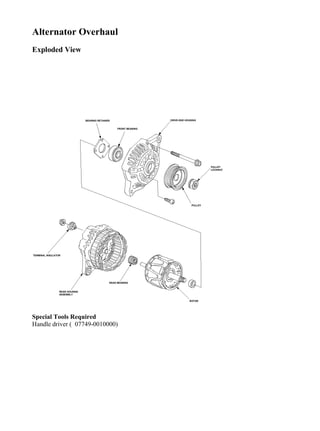
  • 1. Alternator Overhaul Exploded View Special Tools Required Handle driver ( 07749-0010000) BEARING RETAINER FRONT BEARING DRIVE-END HOUSING PULLEY LOCKNUT PULLEY TERMINAL INSULATOR REAR HOUSING ASSEMBLY REAR BEARING ROTOR 1/12Alternator Overhaul 2017/11/18file:///F:/1-aservicemanualpdf.com/manual/ /A0540/2002-2005%20Hond...
  • 2. Driver attachment, 52 x 55 mm ( 07746-0010400) NOTE: Refer to the Exploded View as needed during this procedure. 1. Test the alternator and regulator before you remove them. 2. Remove the alternator. 3. Remove the four through bolts. 2/12Alternator Overhaul 2017/11/18file:///F:/1-aservicemanualpdf.com/manual/ /A0540/2002-2005%20Hond...
  • 3. 4. Heat the rear bearing seat with a 1,000 W hair drier for about 5 minutes (50-60°C, 129-140°F). 5. 3/12Alternator Overhaul 2017/11/18file:///F:/1-aservicemanualpdf.com/manual/ /A0540/2002-2005%20Hond...
  • 4. Separate the rear housing from the drive-end housing by inserting a flat tip screwdriver into the openings and prying them apart. NOTE: Be careful not to damage the stator with the tip of the screwdriver. 6. Separate the rear housing (A) and drive-end housing (B) with the stator (C) attached to the rear housing. A B C 4/12Alternator Overhaul 2017/11/18file:///F:/1-aservicemanualpdf.com/manual/ /A0540/2002-2005%20Hond...
  • 5. 7. If you are not replacing the front bearing and/or rear bearing, go to 15. Clamp the rotor in a soft-jawed vise, then remove the pulley locknut. 8. Remove the rotor using a puller as shown. 5/12Alternator Overhaul 2017/11/18file:///F:/1-aservicemanualpdf.com/manual/ /A0540/2002-2005%20Hond...
  • 6. 9. Inspect the rotor shaft for scoring, and inspect the bearing journal surface in the drive-end housing for seizure marks. • If either the rotor or drive-end housing is damaged, replace the alternator. • If both the rotor and the drive-end housing are OK, go to 10. 10. Remove the rear bearing using the puller as shown. 11. Use a hand press to install the new rear bearing. Apply pressure only on the inner race to avoid damaging the bearing. 6/12Alternator Overhaul 2017/11/18file:///F:/1-aservicemanualpdf.com/manual/ /A0540/2002-2005%20Hond...
  • 7. 12. Remove the front bearing retainer plate. 13. Support the drive-end housing in a vise, and drive out the front bearing with a brass drift (A) and hammer. A 7/12Alternator Overhaul 2017/11/18file:///F:/1-aservicemanualpdf.com/manual/ /A0540/2002-2005%20Hond...
  • 8. 14. With a hammer and the special tools, install a new front bearing in the drive-end housing. 07749-0010000 07746-0010400 8/12Alternator Overhaul 2017/11/18file:///F:/1-aservicemanualpdf.com/manual/ /A0540/2002-2005%20Hond...
  • 9. Alternator Brush Inspection 15. Measure the length of both brushes with a vernier caliper. • If either brush is shorter than the service limit, replace the rear housing assembly. • If brush length is OK, go to 16. Alternator Brush Length: Standard (New): 19.0 mm (0.75 in.) Service Limit: 5 mm (0.2 in.) Rotor Slip Ring Test 16. Check that there is continuity between the slip rings (A). • If there is continuity, go to 17. • If there is no continuity, replace the rotor assembly. B 9/12Alternator Overhaul 2017/11/18file:///F:/1-aservicemanualpdf.com/manual/ /A0540/2002-2005%20Hond...
  • 10. 17. Check that there is no continuity between each slip ring (A) and the rotor (B) and the rotor shaft (C). • If there is no continuity, replace the rear housing assembly, go to 18. • If there is continuity, replace the rotor assembly. Alternator Reassembly 18. If you removed the pulley, put the rotor in the drive-end housing, then tighten its locknut to 111 N·m (11.3 kgf·m, 81.7 lbf·ft). 19. Remove any grease or any oil from the slip rings. 20. Push the brushes (A) in, then insert a pin or drill bit (B) (about 1.8 mm (0.77 in.) diameter) to hold them there. A C 10/12Alternator Overhaul 2017/11/18file:///F:/1-aservicemanualpdf.com/manual/ /A0540/2002-2005%20Hond...
  • 11. 21. Heat the rear bearing seat with a 1,000 W hair drier for about 5 minutes (50-60°C, 129-140° F). 22. Put the rear housing assembly (A) and drive-end housing/rotor assembly (B) together, tighten the four through bolts (C) and pull out the pin (D). AB DA B C 11/12Alternator Overhaul 2017/11/18file:///F:/1-aservicemanualpdf.com/manual/ /A0540/2002-2005%20Hond...
  • 12. 23. After assembling the alternator, turn the pulley by hand to make sure the rotor rotates smoothly and without noise. 24. Install the alternator, and adjust its belt tension. 12/12Alternator Overhaul 2017/11/18file:///F:/1-aservicemanualpdf.com/manual/ /A0540/2002-2005%20Hond...
  • 13. Drive Belt Replacement 1. Loosen the lock bolt (A), mounting bolt (B) and adjusting bolt (C),then remove the drive belt (D). 2. Install the drive belt in the reverse order of removal. 3. Adjust the drive belt tension A B C D 1/1Drive Belt Replacement 2017/11/18file:///F:/1-aservicemanualpdf.com/manual/ /A0540/2002-2005%20Hond...
  • 14. Drive Belt Inspection and Adjustment Special Tools Required Belt tension gauge ( 07JGG-0010100) Belt Tension Gauge Method Inspection 1. Attach the belt tension gauge to the belt and measure the tension. Follow the gauge manufacturer's instructions. If the belt is worn or damaged, replace it. If the belt needs adjustment, go to step 2. Tension: Used Belt: 440-590 N (45-60 kgf, 99-130 lbf) New Belt: 981-1,130 N (100-115 kgf, 220-254 lbf) With A/C compressor: 1/5Drive Belt Inspection and Adjustment 2017/11/18file:///F:/1-aservicemanualpdf.com/manual/ /A0540/2002-2005%20Hond...
  • 15. Without A/C compressor: Adjustment 2. Loosen the lock bolt (A) and mounting bolt (B). 07JGG-0010100 07JGG-0010100 2/5Drive Belt Inspection and Adjustment 2017/11/18file:///F:/1-aservicemanualpdf.com/manual/ /A0540/2002-2005%20Hond...
  • 16. 3. Turn the adjusting bolt (C) to obtain the proper belt tension, then retighten the lock bolt and mounting bolt. 4. Recheck the belt tension. 5. If you installed a new belt, run the engine for 5 minutes, then readjust the belt to the used belt specification. Deflection Method Inspection 1. Apply a force of 98 N (10 kgf, 22 lbf), and measure the deflection at the mid point (A) between the A/C compressor (alternator for without A/C compressor) and crankshaft pulley. If the belt is worn or damaged, replace it. If the belt needs adjustment, go to step 2. Deflection: With A/C compressor: Used Belt: 5.5-8.5 mm (0.22-0.33 in.) New Belt: 3.5-5.0 mm (0.14-0.20 in.) A 8 x 1.25 mm 24 N·m (2.4 kgf·m, 17 lbf·ft) B 10 x 1.25 mm 44 N·m (4.5kgf·m, 33 lbf·ft)C 3/5Drive Belt Inspection and Adjustment 2017/11/18file:///F:/1-aservicemanualpdf.com/manual/ /A0540/2002-2005%20Hond...
  • 17. Without A/C compressor: Used Belt: 7.5-10.5 mm (0.30-0.41 in.) New Belt: 4.5-6.0 mm (0.18-0.24 in.) With A/C compressor: Without A/C compressor: A A 4/5Drive Belt Inspection and Adjustment 2017/11/18file:///F:/1-aservicemanualpdf.com/manual/ /A0540/2002-2005%20Hond...
  • 18. Adjustment 2. Loosen the lock bolt (A) and mounting bolt (B). 3. Turn the adjusting bolt (C) to obtain the proper belt tension, then retighten the lock bolt and mounting bolt. 4. Recheck the belt tension. 5. If you installed a new belt, run the engine for 5 minutes, then readjust the belt to the used belt specification. A 8 x 1.25 mm 24 N·m (2.4kgf·m, 17 lbf·ft) B 10 x 1.25 mm 44 N·m (4.5 kgf·m, 33 lbf·ft)C 5/5Drive Belt Inspection and Adjustment 2017/11/18file:///F:/1-aservicemanualpdf.com/manual/ /A0540/2002-2005%20Hond...
  • 19. Alternator Replacement 1. Disconnect the battery negative cable from the battery. 2. Remove the intake manifold. 3. Disconnect the alternator connector (A), WHT wire (B) and harness clamp (C) from the alternator. 4. Remove the intake manifold 5. Remove the lock bolt (A) and mounting bolt (B), then remove the alternator. 6 x 1.0 mm 8 N·m (0.8 kgf·m, 6 lbf·ft) A B C B 10 x 1.25 mm 44 N·m (4.5 kgf·m, 33 lbf·ft) 1/2Alternator Replacement (Without ETCS) 2017/11/18file:///F:/1-aservicemanualpdf.com/manual/ /A0540/2002-2005%20Hond...
  • 20. 6. Install the alternator in the reverse order of removal. 7. Adjust the drive belt tension. A 8 x 1.25 mm 24 N·m (2.4 kgf·m, 17 lbf·ft) 2/2Alternator Replacement (Without ETCS) 2017/11/18file:///F:/1-aservicemanualpdf.com/manual/ /A0540/2002-2005%20Hond...
  • 21. Charging System Circuit Diagram WHT/BLU YEL CHARGING SYSTEM (1.4W) LIGHT BULB INDICATOR BLK/YEL WHT/BLUWHT/GRN YEL BAT IG1 YELGRN/RED No.1 (80A) SWITCH IGNITION FUSE/RELAY WHT UNDER-HOOD FUSE/RELAY BOX G201 BLK UNDER-DASH FIELD WINDING B C IG L VOLTAGE REGULATOR WHT/RED BLK/YEL ELD UNIT BATTERY ECM/PCM (7.5A) No.16 FR RECTIFIER ALTERNATOR BOX AVN UNIT ECM/PCM No.3 (50A) WHT 1/1Charging System Circuit Diagram 2017/11/18file:///F:/1-aservicemanualpdf.com/manual/ /A0540/2002-2005%20Hond...
  • 22. Charging System Component Location Index CHARGING SYSTEM INDICATOR (In the gauge assembly) UNDER-HOOD FUSE/RELAY BOX (Has built-in ELECTRICAL LOAD DETECTOR (ELD) UNIT) ELD Troubleshooting (Circuit low voltage), ELD Troubleshooting (Circuit high voltage), BATTERY Test, ALTERNATOR Troubleshooting, Replacement, Overhaul, DRIVE BELT Inspection, Replacement, 1/1Charging System Component Location Index (Without ETCS) 2017/11/18file:///F:/1-aservicemanualpdf.com/manual/ /A0540/2002-2005%20Hond...
  • 23. Charging Circuit Troubleshooting If the charging system indicator does not come on or does not go off, or the battery is dead or low, test the following items in the order listed below: Battery Charging system indicator Alternator / regulator circuit Alternator control system Charging System Indicator Test 1. Turn the ignition switch ON (II). Does the charging system indicator come on? YES - Go to 2. NO - Go to 9. 2. Start the engine. Does the charging system indicator go off? YES - Charging system indicator circuit is OK. NO - Go to 3. 3. Turn the ignition switch OFF. 4. Disconnect the alternator 4P connector from the alternator. 5. 1/8Charging Circuit Troubleshooting (Without ETCS) 2017/11/18file:///F:/1-aservicemanualpdf.com/manual/ /A0540/2002-2005%20Hond...
  • 24. Turn the ignition switch ON (II). Does the charging system indicator come on? YES - • Without navigation system: Turn the ignition switch OFF, and repair the short in the WHT/BLU wire. If the WHT/BLU wire is shorted to ground, the voltage regulator in the alternator may be damaged. • With navigation system: Go to 6. NO - Repair the alternator components. 6. Turn the ignition switch OFF. 7. Disconnect the 12P connector from the AVN unit. 8. Turn the ignition switch ON (II). Does the charging system indicator come on? YES - Turn the ignition switch OFF, and repair the short in the WHT/BLU wire. If the WHT/BLU wire is shorted to ground, the voltage regulator in the alternator may be damaged. NO - Check that the terminals are firmly seated at the connectors. If OK, substitute a known- good AVN unit and recheck. 9. Connect the alternator 4P connector terminal No. 3 to body ground with a jumper wire. Turn the ignition switch ON (II). ALTERNATOR 4P CONNECTOR 2/8Charging Circuit Troubleshooting (Without ETCS) 2017/11/18file:///F:/1-aservicemanualpdf.com/manual/ /A0540/2002-2005%20Hond...
  • 25. Does the charging system indicator come on? YES - Go to 10. NO - Turn the ignition switch OFF. Check for a blown No. 16 (7.5 A) fuse and a blown charging system indicator bulb. If the fuse and bulb are OK, repair the open in the YEL or BLK/YEL wire to the indicator bulb. 10. Measure the voltage at the No. 1 terminal of the alternator 4P connector with the ignition switch ON (II). L (WHT/BLU) Wire side of female terminals ALTERNATOR 4P CONNECTOR Wire side of female terminals IG (BLK/YEL) 3/8Charging Circuit Troubleshooting (Without ETCS) 2017/11/18file:///F:/1-aservicemanualpdf.com/manual/ /A0540/2002-2005%20Hond...
  • 26. Is there battery voltage? YES - Go to alternator and regulator circuit test. NO - Repair open in the YEL or BLK/YEL wire between the alternator and the under-dash fuse/relay box. Alternator and Regulator Circuit Test 1. Be sure the battery is sufficiently charged and in good condition. 2. Hook up the following equipment: • Ammeter, 0-400A • Voltmeter, 0-20V (accurate within 0.1 V) 4/8Charging Circuit Troubleshooting (Without ETCS) 2017/11/18file:///F:/1-aservicemanualpdf.com/manual/ /A0540/2002-2005%20Hond...
  • 27. 3. Start the engine. Hold the engine at 3,000 rpm (min-1 ) with no load shift lever in Park or Neutral, until the radiator fan comes on then let it idle. 4. Raise the engine speed to 2,000 rpm (min-1 ) and hold it there. 5. Turn the headlights (high beam) on, and measure voltage at the alternator terminal. Is the voltage between 13.9 and 15.1V? YES - Go to 6. NO - Repair the alternator components. 6. Read the voltage at 13.5V. NOTE: Adjust the voltage by turn the blower motor, rear window defogger, brake lights and etc. on. Is the voltage 60A or more? 5/8Charging Circuit Troubleshooting (Without ETCS) 2017/11/18file:///F:/1-aservicemanualpdf.com/manual/ /A0540/2002-2005%20Hond...
  • 28. YES - Alternator/regulator operation is OK. NO - Repair the alternator components. Alternator Control System Test 1. Check for proper operation of the Electrical Load Detecter (ELD) by checking that the Malfunction Indicator Lamp (MIL) is off and there is no Diagnostic Trouble Code (DTC) for ELD failure. 2. Disconnect the alternator 4P connector from the alternator. 3. Start the engine, and turn the headlights (high beam) ON. 4. Measure voltage between the alternator 4P connector terminal No. 2 and the positive terminal of the battery. Is there 1 V or less? YES - Go to 9. BATTERY ALTERNATOR 4P CONNECTOR C (WHT/GRN) Wire side of female terminals 6/8Charging Circuit Troubleshooting (Without ETCS) 2017/11/18file:///F:/1-aservicemanualpdf.com/manual/ /A0540/2002-2005%20Hond...
  • 29. NO - Go to 5. 5. Turn the headlight and ignition switch OFF. 6. Disconnect the negative cable from the battery. 7. Disconnect Engine Control Module (ECM) /Powertrain Control Module (PCM) connector B (24P). 8. Check for continuity between ECM/PCM connector terminal B18 and body ground. Is there continuity? YES - Repair short to ground in the wire between the alternator and ECM/ PCM. NO - Check that the terminals are firmly seated at the connectors. If OK, substitute a known- good ECM/PCM, and recheck. If prescribed voltage is now available, replace the original ECM/ PCM. 9. Turn the headlight and ignition switch OFF. ECM/PCM CONNECTOR B (24P) ACGC (WHT/GRN) Wire side of female terminals 7/8Charging Circuit Troubleshooting (Without ETCS) 2017/11/18file:///F:/1-aservicemanualpdf.com/manual/ /A0540/2002-2005%20Hond...
  • 30. 10. Disconnect the negative cable from the battery. 11. Disconnect ECM/PCM connector B (24P). 12. Check for continuity between ECM/PCM connector terminal B18 and alternator 4P connector terminal No. 2. Is there continuity? YES - Repair the alternator. NO - Repair open in the wire between the alternator and ECM/ PCM. Wire side of female terminals ECM/PCM CONNECTOR B (24P) ALTERNATOR 4P CONNECTOR ACGC (WHT/GRN) C (WHT/GRN) 8/8Charging Circuit Troubleshooting (Without ETCS) 2017/11/18file:///F:/1-aservicemanualpdf.com/manual/ /A0540/2002-2005%20Hond...
  • 31. Fan Controls Circuit Diagram NOISE G301 SUPPRESSOR NOISE SUPPRESSOR MOTOR RADIATOR FAN 1 2 1 2 1 2 31 2 5 1 3 52 No.3 (50A) (With A/C) BLK/YEL BLU/YEL FAN CONDENSER G301 MOTOR ECM/PCM GRN GRN 93°C (199°F) YEL/BLKWHT BAT IG2 IGNITION SWITCH No.22 (7.5A) UNDER-DASH FUSE/RELAY BOX RELAY FAN CONDENSER UNDER-HOOD FUSE/RELAY BOX BATTERY Closed : Above G101 No.1 (80A) RADIATOR FAN RELAY BLU/BLK RADIATOR FAN SWITCH BLK No.10 (20A) No.11 (30A) GRN 1/1Fan Controls Circuit Diagram 2017/11/18file:///F:/1-aservicemanualpdf.com/manual/ /A0540/2002-2005%20Hond...
  • 32. Radiator Fan Circuit Troubleshooting 1. Check the No. 10 (20A) fuse in the under-hood fuse/relay box, and the No. 22 (15A) fuse in the under-dash fuse/relay box. Is the fuse (s) OK? YES - Go to 2. NO - Replace the fuse (s) and recheck. 2. Remove the radiator fan relay from the under-hood fuse/relay box, and test it. Is the relay OK? YES - Go to 3. NO - Replace the radiator fan relay. 3. Measure the voltage between the No. 2 terminal of the radiator fan relay 5P socket and body ground. RADIATOR FAN RELAY 5P SOCKET 1/8Radiator Fan Circuit Troubleshooting 2017/11/18file:///F:/1-aservicemanualpdf.com/manual/ /A0540/2002-2005%20Hond...
  • 33. Is there battery voltage? YES - Go to 4. NO - Replace the under-hood fuse/relay box. 4. Connect the No. 1 and No. 2 terminals of the radiator fan relay 5P socket with a jumper wire. Terminal side of female terminals JUMPER WIRE RADIATOR FAN RELAY 5P SOCKET Terminal side of female terminals 2/8Radiator Fan Circuit Troubleshooting 2017/11/18file:///F:/1-aservicemanualpdf.com/manual/ /A0540/2002-2005%20Hond...
  • 34. Does the radiator fan run? YES - Go to 5. NO - Go to 6. 5. Disconnect the jumper, and turn the ignition switch ON (II). Check for voltage between the No. 5 terminal of the radiator fan relay 5P socket and body ground. RADIATOR FAN RELAY 5P SOCKET Terminal side of female terminals 3/8Radiator Fan Circuit Troubleshooting 2017/11/18file:///F:/1-aservicemanualpdf.com/manual/ /A0540/2002-2005%20Hond...
  • 35. Is there battery voltage? YES - Go to 9. NO - Check for an open in the wire between the under-hood fuse/relay box and under-dash fuse/relay box. 6. Disconnect the radiator fan motor 2P connector. 7. Check for continuity between the No. 1 terminal of the radiator fan relay 5P socket and the No. 2 terminal of the radiator fan motor 2P connector. RADIATOR FAN RELAY 5P SOCKET Terminal side of female terminals Wire side of female terminals BLU/BLK 4/8Radiator Fan Circuit Troubleshooting 2017/11/18file:///F:/1-aservicemanualpdf.com/manual/ /A0540/2002-2005%20Hond...
  • 36. Is there continuity? YES - Go to 8. NO - Repair open in the wire between the under-hood fuse/relay box and the radiator fan motor 2P connector terminal No. 2. 8. Check for continuity between the No. 1 terminal of the radiator fan motor 2P connector and body ground. RADIATOR FAN MOTOR 2P CONNECTOR RADIATOR FAN MOTOR 2P CONNECTOR BLK 5/8Radiator Fan Circuit Troubleshooting 2017/11/18file:///F:/1-aservicemanualpdf.com/manual/ /A0540/2002-2005%20Hond...
  • 37. Is there continuity? YES - Replace the radiator fan motor. NO - Check for an open in the wire between radiator fan motor 2P connector terminal No. 1 and body ground. If the wire is OK, check for a poor ground at G301. 9. Reinstall the radiator fan relay. 10. Disconnect the radiator fan switch 2P connector. 11. Connect the No. 1 and No. 2 terminals, of the radiater fan switch 2P connector with a jumper wire. Wire side of female terminals JUMPER WIRE RADIATOR FAN SWITCH 2P CONNECTOR 6/8Radiator Fan Circuit Troubleshooting 2017/11/18file:///F:/1-aservicemanualpdf.com/manual/ /A0540/2002-2005%20Hond...
  • 38. Does the radiator fan run? YES - Replace the radiator fan switch. NO - Go to 12. 12. Remove the jumper wire, and measure the voltage between the No. 2 terminal of the radiator fan switch connector and body ground. Wire side of female terminals GRN RADIATOR FAN SWITCH 2P CONNECTOR Wire side of female terminals 7/8Radiator Fan Circuit Troubleshooting 2017/11/18file:///F:/1-aservicemanualpdf.com/manual/ /A0540/2002-2005%20Hond...
  • 39. Is there battery voltage? YES - Check for an open in the wire between radiator fan switch 2P connector terminal No. 1 and body ground. If the wire is OK, check for a poor ground at G101. NO - Repair open in the wire between the radiator fan switch terminal No. 2 and the under- hood fuse/relay box. 8/8Radiator Fan Circuit Troubleshooting 2017/11/18file:///F:/1-aservicemanualpdf.com/manual/ /A0540/2002-2005%20Hond...
  • 40. Thank you very much for your reading. Please Click Here Then Get More Information.