SlideShare a Scribd company logo
1 of 60
Download to read offline
® @
ICHAsld' -------
®
ISPECI er I IOPT I0 I
@~@~
@~ ®~
1
m 1
B
1.
a@
__B*
OE031
ILLUSTRATED SYMBOLS
(Refer to the illustration)
Illustrated symbols CD to @> are designed as
thumb tabs to indicate the chapter's number and
content.
CD General information
<ID Periodic inspection and adjustment
@ Chassis
@ Power train
<ID Engine overhaul
® Cooling system
en Carburetion
® Electrical
® Specifications
@> Optional kit
Illustrated symbols ® to ® are used to identify
the specifications which appear.
® Filling fluid
@ Lubricant
@ Tightening
® Wear limit, clearance
@ Engine speed
@) Special tool
®n,V,A
Illustrated symbols @) to @ in the exploded dia-
gram indicate grade of lubricant and location of
lubrication point.
@) Apply locking agent (LOCTITE®)
@) Apply engine oil
@ Apply gear oil
@ Apply molybdenum disulfide oil
@ Apply wheel bearing grease
@ Apply low-temperature lithium-soap base grease
@ Apply molybdenum disulfide grease
@ Apply Yamabond No.5®
INDEX
GENERAL INFORMATION
PERIODIC INSPECTION AND
ADJUSTMENT
CHASSIS
POWER TRAIN
ENGINE OVERHAUL
COOLING SYSTEM
CARBURETION
ELECTRICAL
SPECIFICATIONS
OPTIONAL KIT
CHAS
SPEC
OPT
______________________________~~~IJieI
CHAPTER 1.
GENERAL INFORMATION
MACHINE IDENTIFICATION ............................. 1-1
FRAME SERIAL NUMBER .......................... 1-1
ENGINE SERIAL NUMBER ......................... 1-1
IMPORTANT INFORMATION ............................ 1-2
PREPARATION FOR REMOVAL AND DIS-
ASSEMBLY .................................................. 1-2
ALL REPLACEMENT PARTS ....................... 1-3
GASKETS, OIL SEALS, AND O-RINGS ...... 1-3
LOCK WASHERS/PLATES AND COTTER
PINS .............................................................1-3
BEARINGS AND OIL SEALS ....................... 1-3
CIRCLlPS ......................................................1-4
SPECIAL TOOLS ................................................ 1-4
FOR TUNE UP .............................................1-4
FOR ENGINE SERVICE ................................ 1-5
FOR POWER TRAIN SERVICE .................... 1-6
FOR ELECTRICAL SERVICE ........................ 1-7
MACHINE IDENTIFICATION II~~~l-:AsI
1-1
lEOOl
GENERAL
INFORMATION
MACHINE IDENTIFICATION
FRAME SERIAL NUMBER
The frame serial number CD is located on the·
right-hand side of the frame (just below the
front of the seat).
ENGINE SERIAL NUMBER
The engine serial number CD is located on the
right-hand side of the crankcase.
NOTE: _______________________
The first three digits of these numbers are for
model identification; the remaining digits are the
unit production number.
Starting Serial Number:
VX500U ......•. SAB-000101 ..
VX500EU ..•...SBp·000101..
VX500STU ....SBN·000101 ..
VX500DXU ... SBB·000101..
VX600U ........8CA·0001 01..
VX600EU ......SCF·000101..
VX600STU ....SCC·000101 ..
VX600DXU ...SCB·000101 ..
NOTE: _________________________
Designs and specifications are subject to change
without notice.
IMPORTANT INFORMATION 1~~~1......1
1-2
lEOll
IMPORTANT INFORMATION
PREPARATION FOR REMOVAL AND DIS-
ASSEMBLY
1. Remove all dirt, mud, dust, and foreign
material before removal and disassembly.
While cleaning, take care to protect the
electrical parts, such as relays, switches,
motor, resistors, controllers, etc., from high
pressure water splashes.
2. Use proper tools and cleaning equipment.
Refer to SPECIAL TOOLS .
3. When disassemblingthe machine, keep mated
parts together. This includes gears, cylinders,
pistons, and other parts that have been
mated through normal wear. Mated parts
must be reused as an assembly or replaced.
4. During disassembly ofthe machine, clean all
parts and place them in trays in the order of
disassembly. This will speed up assembly
time and help ensure that all parts are rein-
stalled correctly.
5. Keep away from fire.
6. Be sure to keep to tightening torque specifi-
cations. When tightening bolts, nuts, and
screws, start with larger-diameter pieces, and
proceed from an inner-positioned one to an
outer-positioned one in a criss-cross pattern.
IMPORTANT INFORMATION 1~~~1.1LI
300-000
300-002
300-003
'-3
ALL REPLACEMENT PARTS
1.We recommend use ofYamaha genuine parts
for all replacements. Use oil and/or grease
recommended by Yamaha for assembly and
adjustment.
GASKETS, OIL SEALS, AND O-RINGS
1. All gaskets, seals, and a-rings should be re-
placed when an engine is overhauled. All
gasket surfaces, oil seal lips, and a-rings must
be cleaned.
2. Properly oil all mating parts and bearings
during reassembly. Apply grease to the oil
seal lips.
LOCK WASHERS/PLATES AND COTTER
PINS
1. All lock washers/plates CD and cotter pins
must be replaced when they are removed.
Lock tab(s) should be bent along the bolt or
nut flat(s) after the bolt or nut has been prop-
erly tightened.
BEARINGS AND OIL SEALS
1.lnstall the bearing(s) CD and oil seal(s) ®
with their manufacturer's marks or numbers
facing outwards. (In other words, the
stamped letters must be on the side exposed
to view.) When installing oil.seal(s), apply a
light coating of lightweight lithium base
grease to the seal lip(s). Oil the bearings
liberally when installing.
Do not use compressed air to spin the bearings
dry. This causes damage to the surface of the
bearings.
IMPORTANT INFORMATION/SPECIAL TOOLS I~~~I~I
300·001
1-4
CIRCLlPS
1. All circlips should be inspected carefully be-
fore reassembly. Always replace piston pin
clips after one use. Replace misshapen
circlips. When installing acirclip D, make sure
that the sharp edged corner ® is positioned
opposite to the thrust ID it receives. See the
sectional view.
@ Shaft
lE021
SPECIAL TOOLS
Some special tools are necessary for completely
accurate tune-up and assembly. Using the correct
special tool will help prevent damage that can be
caused by the use ofimpropertools or improvised
techniques.
NOTE: _______________________
Be sure to use the correct part number when
ordering the tool, since the part number differs
according to the area as shown below. The first
part number is for Europe, and the second part is
for the U.S.A. and Canada.
e.g. 90890 - *****, YU- *****
FORTUNE UP
• Sheave Gauge
PIN YS-91047-3 D, YS-39506-5 ®
This gauge is used to measure sheave distance
and for offset adjustment.
lE041
• Dial Gauge
PIN 90890-03097, YU-03097
This gauge is used for run out measurement.
1-5
SPECIAL TOOLS I~~~I~IlE051
• Fuel Level Gauge
PIN 90890-01312, YM-01312-A
This gauge is used to measure the fuel level in the
float chamber.
lE061
• Vacuum Gauge
PIN -, YS-33275
This gauge is used for carburetor synchroniza-
tion.
1E071
FOR ENGINE SERVICE
• Piston Pin Puller
PIN 90890-01304, YU-01304
This tool is used to remove the piston pin.
lE081
• Rotor Puller
PIN 90890-01362, YU-33270
This tool is used to remove the magneto rotor.
lE091
• Cooling System Tester
PIN 90890-01325, YS-22460-01
This tester is used for checking cooling system.
'-6
SPECIAL TOOLS II~~~I~IlEl0l
FOR POWER TRAIN SERVICE
• Primary Sheave Holder
PIN 90890-01701, YS-01880
This tool is used to hold the primary sheave.
lElll
• Primary Sheave Puller (18 mm)
PIN YS-01881-1 CD, YS-38517 CV
Thistool is used for removing the primary sheave.
lE121
• Clutch Spider Separator
PIN 90890-01711, YS-28890-8
This tools are used when disassembling and as-
sembling the primary sheave.
lE131
• Clutch Separator Adapter
PIN 90890-01740, YS-34480
This tool is used when disassembling and assem-
bling the primary sheave.
lE171
• Clutch busing jig kit
PIN YS-39752
Thistool is used when removing and installing the
primary sheave busing.
1-7
SPECIAL TOOLS II~~~ISsI
1E141
• Track Clip Installer
PIN 90890-01721. YS-91045-A
This tool is used for installing the track clip.
1E151
FOR ELECTRICAL SERVICE
• Pocket Tester
PIN 90890-03112. YU-03112
This instrument is necessary for checking the
electrical components.
1E161
• Electra Tester
PIN 90890-03021. YU-33260-A
This instrument is invaluable for checking the
electrical system.
__________I':g!I-.1
CHAPTER 2.
PERIODIC INSPECTIONS
AND ADJUSTMENTS
INTRODUCTION ................................................2-1
PERIODIC MAINTENANCE TABLE ................... 2-1
ENGINE .....................................................•........2-3
SPARK PLUG ...............................................2-3
OIL PUMP ....................................................2-4
OIL FILTER INSPECTION ..........................•.2-6
FUEL LINE INSPECTION .............................2-6
FUEL FILTER INSPECTION ..............•..........2-6
COOLING SYSTEM ............................•.....•.•2-7
CARBURETOR SYNCHRONIZATION •••.... 2-12
ENGINE IDLE SPEED ADJUSTMENT •..... 2-13
THROTTLE CABLE ADJUSTMENT .......••• 2-13
THROTTLE OVERRIDE SYSTEM (T.O.R.S.)
CHECK ............................................•.•......2-14
STARTER (CHOKE) CABLE
ADJUSTMENT ........................................2-14
POWER TRAIN .................................................2-15
DRIVE V-BELT............................................2-15
ENGAGEMENT SPEED CHECK ................2-17
BRAKE ADJUSTMENT .................................... 2-18
BRAKE PAD INSPECTION ........................ 2-18
DRIVE CHAIN .............................................2-18
TRACK TENSION ADJUSTMENT ............ 2-20
SLIDE RUNNER INSPECTION .................. 2-21
CHASSIS ..........................................................2-22
SKI/SKI RUNNER .......................................2-22
STEERING SYSTEM ..................................2-22
HEADLIGHT BEAM ADJUSTMENT .........2-23
LUBRICATION ...........................................2-24
TUNING ............................................................2-25
CARBURETOR TUNING ............................2-25
CLUTCH TUNING ......................................2-36
GEARING SELECTION ..............................2-38
HIGH ALTITUDE TUNING ...............................2-41
INTRODUCTION/PERIODIC MAINTENANCE TABLE I':g~I_I2EOO5
PERIODIC INSPECTIONS AND ADJUSTMENTS
INTRODUCTION
This chapter includes all information necessary to perform recommended inspections and adjustments.
These preventive maintenance procedures, iffollowed, will ensure more reliable machine operation and
a longer service life. In addition, the need for costly overhaul work will be greatly reduced. This
information applies to machines already in service as well as new machines that are being prepared for
sale. All service technicians should be familiar with this entire chapter.
PERIODIC MAINTENANCE TABLE
First Every
Pre- Month Season
Item Remarks operation or or
check first 800 km 3,200 km
(Daily) (500 Mi) (2,000 Mi)
(40 hr) (160 hr)
Spark Plug:
Check condition adjust the gap and clean.
•Replace if necessary.
Check oil level.
•Engine Oil:
*Air bleed the oil pump if necessary.
•
*Oil Filter:
Check condition.
•Replace if necessary.
Fuel: Check fuel level.
•Check condition.
*Fuel Filter: Replace if necessary. •
*Fuel Line:
Check fuel hose for cracks or damage.
•Replace if necessary.
*Oil Line:
Check oil hose for cracks or damage.
•Replace if necessary.
Check coolant level.
•Engine Coolant
*Air bleed the cooling system if necessary.
•Check throttle lever operation.
•Carburetor Whenever operating condition
*Adjust the jets. (elevation!temperature) is changed.
Check wear and damage. Replace if necessary.
•*Water Pump Belt
Adjust water pump belt if necessary.
•
Manual Starter:
Check operation and rope damage.
•*Replace if necessary.
Engine Stop Switch:
Check operation
•*Repair if necessary.
Throttle 9verride System:
Check operation.
•*Repair if necessary.

Check operation.
Throttle Lever:
*Repair if necessary. •
*Exhaust System:
Check for leakage.
•Retighten or replace gasket if necessary.
*Decarbonization: More frequently if necessary.
•
Drive V-belt Guard:
Check cracks, bends or damage.
•*Replace if necessary.
Drive V-belt: Check wear and damage. Replace if necessary.
•
Drive Track/Idler Wheels:
Check deflection, wear and damage.
•*Adjust/replace if necessary.
Slide Runner
Check wear and damage.
•*Replace if necessary.
•*: It is recommended that these items be serviced by a Yamaha dealer or other qualified mechanic.
2-1
_ _ _ _ _~_ _ _ _ IIANDSJPllo)lPERIODIC MAINTENANCE TABLE _ _~ _
First Every
Pre- Month Season
Item Remarks operation or or
check first 800 km 3,200 km
(Daily) (500 Mi) (2,000 Mi)
(40 hr) (160 hr)
Check operation.
•Brake/
*Adjust free play and/or replace pads if neces-
Parking Brake
sary. •Check oil level.
•*Drive Chain Oil
Replace.
•
*Drive Chain:
Check deflection.
**.Adjust if necessary.
Ski/ Check wear and damage.
•Ski Runner *Replace if necessary.
•
Steering System
Check operation.
•*Adjust toe-out if necessary.
•
Lights:
Check operation.
•Replace bulbs if necessary.
Check fluid level.
•Battery *Check specific gravity and breather pipe opera-
tion.
•Charge/Correct if necessary.
Check engagement and shift speed.
•Adjust if necessary. Wheneveroperatingelevation ischanged.
*Primary Sheave Check wear and damage.
•Replace if necessary.
Lubricate with specified grease.
•Lubricate with specified grease.
•*Secondary Sheave
Adjust if necessary. Whenever operating elevation ischanged.
*Steering Column Bearing: Lubricate with specified grease.
•*Ski and Front Suspension: Lubricate with specified grease.
•*Suspension Component: Lubricate with specified grease.
•*Brake Cable End and Lubricate with specified grease.
•Lever End/ Throttle Check cable damage.
Cable End Replace if necessary. •
Shroud Latches: Make sure the shroud latches are hooked.
•
Fittings/Fasteners:
Check tightness.
•*Repair if necessary.
Service Tools/Spare Parts: Check proper placement.
•*: It is recommended that these items be serviced by a Yamaha dealer or other qualified mechanic.
**: Perform after 1 Month or 80 km (50 Mi) and every 1 Month or 800 km (500 Mi).
2-2
_________________________S_M_R_K_PL_U__G p:gSI~1
®*=::::::::;~I/)
377-000
(·~_J1-)CD..' fi...----~41
2-3
2EOll
ENGINE
SPARK PLUG
1. Remove:
• Spark plug
2. Inspect:
• Electrode CD
Wear/Damage~Replace.
• Insulator color ®
3. Measure:
• Plug gap@
Out of specification~Regap.
Use wire thickness gauge.
Spark plug gap:
0.7 - 0.8 mm (0.028 - 0.032 in)
Clean the plug with a spark plug cleaner if
necessary.
Standard spark plug:
BR9ES (NGK)
Before installing a spark plug, clean the
gasket surface and plug surface.
4. Tighten:
• Spark plug
Spark plug:
28 Nm (2.8 m • kg, 20 ft • Ib)
NOTE: ________________________
Finger-tighten CD the spark plug before torquing
® to specification.
_________________________O_I_LP_U_M_P II:g~ltill
2-4
2E021
OIL PUMP
Air Bleeding
The oil pump and delivery line must be bled on
the following occasions:
• When any portion of the oil system has been
disconnected.
• When the machine has been turned on its side.
• Whenever the oil tank has been run empty.
• During pre-delivery.
1. Remove:
• Reservoir tank ill
2. Fill:
• Oil tank ill
Oil tank capacity:
2.9 L (2.6 Imp qt, 3.1 US qt)
Recommended oil:
Vamalube 2-cycle oil
3. Loosen the oil tank bolt ®.
4. Place a rag under the oil pump assembly to
catch oil.
5. Disconnect:
• Oil hose ill
6. Keep the oil running out until air bubbles
disappear from the oil hose ill.
7. Connect:
• Oil hose ill
8. Disconnect:
• Oil delivery hoses ill
9. Feed the uYamalube 2-cycle oil into the oil
delivery hoses ill using an oil can ® for com-
plete air bleeding.
10. Connect:
• Oil delivery hoses ill
_________________________O_I_LP_U_M_P II:g!I~1
2-5
11. Remove:
• Bleed screw D
• Gasket (bleed screw)
12. Keep the oil running out until air bubbles
disappear from bleed hole.
13. Inspect:
• Gasket (bleed screw)
Wear/Damage ~ Replace.
14. Install:
• Gasket (bleed screw)
• Bleed screw
Cable Adjustment
NOTE: _________________________
Before adjusting the oil pump cable, the throttle
cable distcmce should be adjusted.
Adjustment steps:
• Loosen the locknut D.
• Turn the adjuster® in or out until the speci-
fied distance is obtained.
~
Distance® :
VX500(E)fSTfOX:
25 - 27 mm (0.98 - 1.06 in)
VX600(ElfSTfOX:
27 - 29 mm (1.06 -1.14 in)
Turning in Distance ® is increased.
Turning out Distance ® is decreased.
• Tighten the locknut and push in the adjuster
cover.
800-001
801·002
8OHl03
OIL FILTER INSPECTION II:g~ItAI
2-6
2E031
OIL FILTER INSPECTION
1. Remove:
• Oil filter CD
NOTE: _______________________
Plug the oil hoses so that the oil will not run outof
the oil tank and oil pump.
2. Inspect:
• Oil filter CD
Contamination ~ Replace.
Recommended replacement interval:
Every season
3. Reverse the removal procedure.
2E041
FUEL LINE INSPECTION
1. Inspect:
2E051
• Fuel hoses
• Fuel delivery hoses
Crack/Da mage~Replace.
FUEL FILTER INSPECTION
1. Remove:
• Seat
2. Disconnect:
• Tail/brake light coupler
3. Remove:
• Spring bands CD
• Cap®
• Fuel filter @
4. Inspect:
• Fuel filter CD
Contamination ~ Replace.
Recommended replacement interval:
Every season
5. Reverse the removal procedure.
COOLING SYSTEM ~
------------------------------------------------------
IlANOSJP Ito) I
2-7
2E061
COOLING SYSTEM
Coolant Replacement
NOTE: _______________________
The coolant should be changed at least
seasonally.
1. Place the machine on a level surface.
2. Remove:
• Side cowling (right)
• Seat
• Muffler CD
• Exhaust pipe ®
3. Remove:
• Coolant filler cap CD
A WARNING
Do not remove the coolant filler cap CD when the
engine is hot. Scalding hot fluid and steam may
be blown out under pressure, which could cause
serious injury. When the engine has cooled, place
thick rag like atowel overthe radiator cap, slowly
rotate the cap counterclockwise to the detent.
This procedure allows any residual pressure to
escape. When the hissing sound has stopped,
press down on the cap while turning
counterclockwise and remove it.
4. Place an open container under the drain bolts
CD·
S.Remove:
• Drain bolts
6. Drain the coolant.
NOTE: _________________________
Lift up the tail ofthe machine to drain the coolant.
o
2-8
COOLING SYSTEM 1':gS14rl1
7. Disconnect:
• Coolant hoses CD (rear)
8. Drain the coolant.
NOTE:____________
Liftupthe front ofthe machineto drainthe coolant
completely.
A WARNING
Coolant is poisonous. It is harmful or fatal if
swallowed.
• Ifcoolantisswallowed, induce vomiting imme-
diately. Get immediate medical attention.
• If coolant splashes in eyes, flush with water.
Call a physician.
• If coolant splashes on skin or clothes, wash
immediately with soap and water.
9. Remove the reservoir tank CD and drain the
coolant.
10. Install:
• Reservoir tank
11. Inspect:
• Gaskets (drain bolt)
Damage~Replace.
12. Install:
• Gaskets
• Drain bolts
• Exhaust pipe/gaskets
• Muffler
13. Fill:
Drain bolt:
23 Nm (2.3 m· kg, 17 ft· Ib)
Bolts (exhaust pipe):
23 Nm (2.3 m • kg, 17 ft· Ib)
• Cooling system
Recommended Coolant:
High quality ethylene glycol
anti-freeze containing
corrosion inhibitor
Coolant and water mixed ratio:
SO%: 400/0
Total amount:
VX500(E)/VXSOO(E)/VX500DX/
VXSOODX
4.2 L (3.70 Imp qt, 4.44 US qt)
VX500ST/VXSOOST
4.S L (4.05 Imp qt, 4.8S US qt)
Reservoir tank capacity:
0.2 L (0.18 Imp qt, 0.21 US qt)
_ _________ IIANDSJPI ..~ ICOOLING SYSTEM _ _~ _
2-9
• Hard water or salt water is harmful to the
engine parts; use boiled or distilled water.
• Do not use water containing impurities or oil.
14. Bleed air from the cooling system.
15. Inspect:
• Cooling system
Decrease of pressure (leaks)~Repair as re-
quired. (see page 6-4)
Inspection steps:
• Attach the Cooling System Tester D (90890-
01325, YU-22460-01) to the coolant fi lIer ®.
• Apply 100 kPa (1.0 kg/cm2, 14 psi).
• Measure the pressure with gauge.
2E071
Air bleeding
1. Bleed air from the cooling system.
Air bleeding steps:
• Lift up the tail of the machine.
• Connect plastic tubes D tightly to the bleed
screws ® on the heat exchanger.
• Loosen the bleed screws ® of Heat ex-
changer.
• Keep the coolant running out until air bub-
bles disappear, while adding coolant slowly
to the radiator.
• Tighten the bleed screws.
~ Bleed screw:
~ 6 Nm (0.6 m • kg, 4.3 ft • Ib)
• Add coolant to fill the specified level ®.
• Loosen the bleed bolt @ on the water pump
housing.
• Keep the coolant running out until air bub-
bles disappear.
• Tighten the bleed bolt.
Bleed bolt:
6 Nm (0.6 m • kg, 4.3 ft • Ib)
_ _ _ _ _ _ _ _ _ _ _ 1lANDSJP 1~ ICOOLING SYSTEM . . ~ .
2·10
• Install the radiator cap.
Apply and lock the parking brake. Start the
engine and run it at approximately 2500 ...
3000 rpm until the thermostat opens and the
coolant circulates (approximately 3 ... 5 min-
utes). The rear heat exchanger will be warm
to the touch.
A WARNING
To avoid severe injury or death:
• Makesurethe machineissecurely supported
with a suitable stand.
• Do not exceed 3000 rpm. The machine could
unexpectedly move forward if the clutch
engages, ordrive line damage and excessive
V-belt wear could occur.
• Operate the engine only in a well-ventilated
area.
• Remove the radiator cap and bleed air on the
cooling system again, as shown in the steps
above.
No air bubbles ~ OK.
• Add coolant up to the specified level.
• Pour coolant into the reservoir tank CD until
the coolant level reaches HFULLHlevel mark.
2E081
Water Pump Belt Deflection Adjustment
1. Remove:
• Muffler
2. Check:
• Drive belt deflection
Out of specification~Adjust.
Drive belt deflection
8 mm (0.31 in)/
8 kg (17.6Ib)
(NEW BELT)
8 mm (0.31 in)/
13 ... 20 kg (28.7 ... 44.1 Ib)
3. Adjust:
• Drive belt deflection
Adjustment steps:
• Remove the recoil starter CD.
• Attach the Primary Sheave Holder (90890-
01701, YS-01880)to hold the primarysheave.
2-11
COOLING SYSTEM II~g!Itll
• Remove the starter pulley 0.
• Remove the screws @ of the starter pulley.
• Adjust the drive belt deflection by adding or
removing a shim G).
Add shim Tension becomes lower.
Remove shim Tension becomes higher.
Shim size
Part number Thickness
8CA-15721-00 0.5 mm (0.02 in)
8CA-15722-00 1.0 mm (0.04 in)
• Install the starter pulley and drive belt.
• Recheck the drive belt deflection. If out of
specification, readjust the drive belt deflec-
tion.
4. Tighten:
Starter pulley bolt:
23 Nm (2.3 m· kg, 17 ft· Ib)
Recoil starter bolt:
10 Nm (1.0 m • kg, 7.2 ft· Ib)
_ _ _ _ _ _ _ _ _ _ liANOSJPlfO) ICARBURETOR SYNCHRONIZATION . . ~ .
2-12
2E094
CARBURETOR SYNCHRONIZATION
1. Remove:
• Carburetor assembly
(see page 7-2)
2. Adjust:
• Carburetor synchronization
Adjustment steps:
• First adjustthe throttle valve height@ at the
No.2 carburetor by turning the throttle stop
screw CD until the specified height is ob-
tained.
I~
Throttle valve height:
VX500 (E)/ST/DX:
1.5 mm (0.059 in)
VX600 (E)/ST/DX:
1.6 mm (0.063 in)
• Second adjust the throttle valve height@on
the No.1® carburetor with adjusting eccen-
tric nut@.
• Move the throttle lever 2 - 3 times.
• Make sure all the carburetor throttle valves
are on the same height.
• Install the carburetor.
• Remove the air chamber and then plug the
hole in the carburetor joint with plug and
connect the Vacuum Gauge (YS-33275) to
the fitting.
• Start the engine and let it warm up.
• If vacuum reading are not same, turn the
adjusting eccentric nut@inoroutsothatthe
vacuum reading are the same.
NOTE: ______________________
When read the vacuum gauge, make sure
carburetor covers G) are installed.
ENGINE IDLE SPEED ADJUSTMENT/ IINSPI(0) ITHROTTLE CABLE ADJUSTMENT ADJ ~
L...:.':'::;';:;......_';;;:'=..I
2-13
2El0l
ENGINE IDLE SPEED ADJUSTMENT
1.Adjust:
• Engine idle speed
Adjustment steps:
• Start the engine and let it warm up.
• Turn the throttle stop screws CD in or out
to adjust the engine idle speed.
Turning in Idle speed becomes higher.
Turning out Idle speed becomes lower.
Cl Engine idle speed:
1,450 - 1,650 r/min
NOTE:
After adjusting the engine idle speed, the
throttle cable free play should be adjusted.
2E131
THROTTLE CABLE ADJUSTMENT
NOTE: _______________________
Before adjusting the throttle cable free play, the
engine idle speed should be adjusted.
1. Measure:
• Throttle cable free play ®
Out of specification~Adjust.
Throttle cable free play:
1.0 - 2.0 mm (0.04 - 0.08 in)
2. Adjust:
• Throttle cable free play
Adjustment steps:
• Loosen the locknut CD.
• Turn the adjuster ® in or out until the speci-
fied free play is obtained.
Turning in Free play is increased.
Turning out Free play is decreased.
• Tighten the locknut.
THROTTLE OVERRIDE SYSTEM (T.O.R.S.) CHECKI IINSPI(0) ISTARTER (CHOKE) CABLE ADJUSTMENT ADJ ~
a...:....;;.::;;..;::;~_-=-.=..I
®
2·14
2El22
THROTTLE OVERRIDE SYSTEM (T.O.R.S.)
CHECK
A WARNING
When checking T.O.R.S.:
• Be sure the parking brake is applied.
• Be sure the throttle lever moves smoothly.
• Do not run the engine upto clutch engagement
rpm. Otherwise. the machine could start
moving forward unexpectedly. which could
cause and accident.
1. Start the engine.
NOTE: _______________________
Refer to STARTING THE ENGINE.
2. Hold the pivot point ofthe throttle lever away
from the throttle switch CD.
3. Press CV the throttle lever gradually.
The T.O.R.S warning light should turn on and
off and the engine should run between 2800
and 3000 rpm.
A WARNING
Ifthe engine does not run between 2800 and 3000
rpm. stop the engine by turning the main switch
to OFF position and consult a Yamaha dealer.
2E131
STARTER (CHOKE) CABLE ADJUSTMENT
1. Pull the outer tube of starter cable CD upward.
2. Measure:
• Starter cable free play ®
Out of specification -7 Adjust.
Freeplay@:
0.5 .. 1.5 mm (0.02 .. 0.06 in)
3. Adjust:
• Starter cable free play
Adjustment steps:
• Loosen the locknut CD.
• Turn the adjuster CV in or out until the speci-
fied free play is obtained.
Turning in Free play is increased.
Turning out Free play is decreased.
• Tighten the locknut and push in the adjuster
cover.
________________________D_R_IV_E_V_-B_El__T p:gSI~1
2E141
POWER TRAIN
DRIVE V-BELT
A WARNING
• Be sure there are shims (2 pes) CD between
secondary fixed and sliding sheaves when·
installing the NEW belt.
805030 • Ifthere is no gap, the clutch engagement speed
L-_ _ _ _ _ _....;;;~;;..-._ _ _ _ _ _..... will be reduced. The machine may move
805-029
805-020
2-15
unexpectedly when the engine is started.
• The spacer of the secondary sheave should be
adjusted.
To ensure proper clutch performance, the
spacers in the secondary clutch must be
repositioned as the V-belt wears.
 V-belt width CD
Number
of spacers
~ 31.6 mm (1.24 in) or more 2 spacers
00.l 30.6 mm (1.20 in) 1 spacer
[9 29.6 mm (1.17 in) No spacer
28 mm (1.1 in) or less
Replace the
V-belt
1. Remove:
• Drive V-belt guard CD
________________________D_R_IV_E_V_-B_El___• P:g!I~1
805-009
2-16
2. Remove:
• Drive V-belt CD
Removal steps:
• Rotate the secondary sliding sheave clock-
wise ® and push it @ so that it separates
from the fixed sheave.
• Pull @ the belt up over the secondary fixed
sheave.
• Remove the belt from the secondary sheave
and primary sheave.
3. Inspect:
• Drive V-belt
CrackJWear/Damage ~ Replace.
Oil orgrease adhering tothe V-belt ~ Check
the primary and secondary sheaves.
4. Inspect:
• Primary sheave
• Secondary sheave
Oil or grease adhering to the primary and
secondary sheaves ~ Remove the oil or
grease using a rag soaked in lacquerthinner
or solvent. Check the primary and secon-
dary sheaves.
5. Measure:
• Drive V-belt length ®
Out of specification ~ Replace.
Drive V-belt length:
1,130 - 1,118 mm (44.5 - 44.0 in)
ENGAGEMENT SPEED CHECK I':gsI_I
2-17
2E201
ENGAGEMENT SPEED CHECK
1. Place the machine on a level area of hard
packed snow.
2. Check:
• Clutch engagement speed
Checking steps:
• Start the engine, and open the throttle lever
gradually.
• Check the engine speed when the machine
starts moving forward.
Out of specification ~ Adjust the primary
sheave. (see page 2-36)
C) Engagement speed:
VX500(E)fSTfDX
Approx. 3,700 rfmin
VX600(E)fSTfDX
Approx. 3,600 rfmin
®
~I
I
I
I
I
I
I
I
I
_J
BRAKE PAD INSPECTION/DRIVE CHAIN II~gjI_I
2-18
2E161
BRAKE ADJUSTMENT
BRAKE PAD INSPECTION
1. Apply the brake lever.
2. Measure:
• Brake pad thickness ®
Out of specification ~ Replace brake pads
as a set. (see page 4-27)
I~ Wear limit:
v ~ 5.2 mm (0.2 in)
NOTE: _________________________
Adjust brake every 40 hours of operation, or
whenever the brake lever becomes loose during
operation.
3. Measure:
• Distance L
Out of specification --) Adjust.
Distance ULU
69.0 ~ 71.0 mm (2.72 ~ 2.8 in)
4. Adjust:
• Distance L
Adjustment steps:
• Loosen the locknut CD.
• Turn the adjuster CV in or out until the speci-
fied distance is obtained.
Turning in Distance uLu is increased.
Turning out DistanceuLU is decreased.
• Tighten the locknut CD.
2E171
DRIVE CHAIN
Oil Level Inspection
1. Place the machine on a level surface.
2. Remove:
• Muffler
3. Place a rag under the checking hole CD (oil
level).
4. Remove:
• Checking bolt CV
• Gasket (checking bolt)
_____________D_RI_VE_C_H_A_IN p:gjI_I
2-19
5. Inspect:
• Oil level (drive chain housing)
Oil flows out ~ Oil level is correct.
Oil does not flow out ~ Oil level is low.
Add oil until oil flows out.
Recommended oil:
Gear oil API GL-3 SAE #75 or #80
6. Inspect:
• Gasket (checking bolt)
Damage ~ Replace.
7. Tighten:
Checking bolt:
10 Nm (1.0 m· kg, 7.2 ft· Ib)
Oil Replacement
Oil replacement step:
• Warm up the engine for several minutes.
• Remove the Muffler.
• Place some rags under the chain housing
and place a small gutter to channel the oil
into the hole.
• Lift up the front of the machine.
• Remove the drain plug CD.
Be sure to remove any oil from the heat protec-
tor.
2E182
Recommended oil:
Gear oil API GL-3 SAE #75 or #80
Oil capacity:
VX500 (E)/500ST/600(E)/600ST:
250 cm3 (8.8 Imp OZ, 8.5 US OZ)
VX500DX/600DX:
300 cm3 (10.6 Imp OZ, 10.1 US OZ)
Chain Slack Adjustment
1. Adjust:
• Drive chain slack
Adjustment steps:
• Loosen the locknut CD and unthread sealing
washer CV slightly.
• Turn the adjuster @ in until it is finger tight.
• Tighten the locknut.
CD ...®
TRACK TENSION ADJUSTMENT I':gsI_I
820003
820-004
2-20
2E151
TRACK TENSION ADJUSTMENT
A WARNING
A broken track, track fittings, or debris thrown
by the track could be dangerous to an operator
or bystanders. Observe the following
precautions.
• Do not allow anyone to stand behind the
machine when the engine is running.
• When the rear of the machine is raised to allow
the track to spin, a suitable stand must be used
to support the rear ofthe machine. Never allow
anyone to hold the rear of the machine off the
ground to allow the track to spin. Never allow
anyone near a rotating track.
• Inspect track condition frequently. Replace the
track if it is damaged to the depth where fabric
reinforcement material is visible.
• Never install studs (cleats) closer than three
inches to the edge of the track.
1. Place the machine with the right side facing
down.
2. Measure:
• Track deflection CD
Pull at the track center window exerting a
force of 10 kg (22 Ib) using a spring scale 0.
Out of specification ~ Adjust.
Track deflection:
25 .. 30 mm (0.98 .. 1.18 in)
3. Adjust:
• Track deflection
Adjustment steps:
• Lift the rear of the machine onto a suitable
stand to raise the track off the ground.
• Loosen the rear axle nut CD.
NOTE: ____________
It is not necessary to remove the cotter pin 0.
TRACK TENSION ADJUSTMENT! IINSPIto) ISLIDE RUNNER INSPECTION ADJ ~
L...:.,':'=;':.L--=.=...I
820-008
820-005
@+
820009
~ ~
~..... _ _ _ _ _ _ _ .J
820-001
a. Starttheengine and rotate the track one or
two turns. Stop the engine.
b. Check the track alignment with the slide
runner CID.
If the alignment is incorrect. turn the left
and right adjusters to adjust.
Track alignment
@ Shifted (j) Shifted
to right to left
@ Left adjuster Turn out Turn in
CID Right adjuster Turn in Turn out
® Slide runner ® Track
@ Track metal ® Gap @ Forward
c. Adjust track deflection to the specified
amount.
Track deflection
More than Less than
specified specified
@ Left adjuster Turn in Turn out
CID Right adjuster Turn in Turn out
The adjusters should be turned an equal
amount.
• Recheck alignment and deflection. If neces-
sary, repeat steps a to c until proper adjust-
ment is achieved.
• Tighten the rear axle nut.
Rear axle nut:
75 Nm (7.5 m • kg, 54 ft· Ib)
SLIDE RUNNER INSPECTION
1. Inspect:
• Slide runner CD
Cracks/DamageMlear~Replace.
2. Measure:
• Slide runner thickness CV
Out of specification~Replace.
(see page 4-33)
~ W~~!:~:03::,_n_)______--J
IlANDSJP Ito) ISKI/SKI RUNNER/STEERING SYSTEM ~
------------------------------------------------------
2·22
2E212
CHASSIS
SKI/SKI RUNNER
1. Check:
• Ski
• Ski runner
• Ski cover
Wear/Damage ~ Replace.
Ski runner wear limit G):
8 mm (0.31 in)
Do not operate the machine without the ski cover
to prevent ski wear and damage.
2E221
STEERING SYSTEM
Free Play check
1. Check:
• Steering system free play
Push the handlebar up and down and back
and forth.
Turn the handlebar slightly to the right and
left.
Excessive free play ~ check to be sure the
handlebar, tie rod ends and relay rod ends
are installed securely in position.lffree play
still exists, check the steering bearing front
suspension links and ski mounting area for
wear, and replace if necessary.
(see page 3-9)
IlANDSJP. I(0) ISTEERING SYSTEM/HEADLIGHT BEAM ADJUSTMENT ~
------------------------------------------------------
2-23
2E232
Toe-Out Adjustment
1. Place the machine on a level surface.
2. Check:
• Ski toe-out
Direct the skis straight forward.
Out of specification~Adjust.
Ski toe - out (@ - @):
0.0 .. 15.0 mm (0.0 .. 0.6 in)
Ski stance (6) (center to center):
1,010 mm (39.8 in)
3. Adjust:
• Ski toe-out
Adjustment steps:
• Loosen the locknuts CD (tie-rod).
• Turn the relay rod ® in or out until the
specified toe-out is obtained.
• Tighten the locknuts CD (tie-rod).
Locknut (rod end):
X 25 Nm (2.5 m· kg, 18 ft· Ib)
LOCTITE®
~ Left side
[§] Right side
2E241
HEADLIGHT BEAM ADJUSTMENT
1. Place the machine on a level surface.
2. Inspect:
• Headlight beam direction
L
H
The high beam should be directed down-
wards at an angle of 1/20
to the horizontal.
If not, adjust the direction.
3.0 m (10 ft) 7.6 m (25 ft)
26 mm (1.0 in) 66 mm (2.6 in)
3. Adjust:
• Headlight beam direction
Adjust the headlight beam by tightening or
loosening the adjusters CD.
LUBRICATION ~
------------------------------------------------------
IlANOSJP Ito) I
A
2-24
2E251
LUBRICATION
Brake Lever, Brake Cable End and
Throttle Lever
1. Lubricate the brake lever pivot. brake cable
end and throttle lever.
I_IESSO Beacon 325 Grease
A WARNING
Apply a dab of grease to the cable end only.
Do not grease the brake/throttle cables
themselves because they could become frozen,
which could cause loss of control.
2E261
Front and Rear ~uspension
1.lnjectgreasethrough nipplesG) using agrease
gun.
--.. Esso Beacon 325 Grease or
Aeroshell Grease #7A.
g] Front
[ID Rear
IlANDSJP I~ ICARBURETOR TUNI~G ~
-----------------------------------------------
2·25
2E271
TUNING
CARBURETOR TUNING
The carburetor is set at the factory to run at
temperatures of O°C .. -20°C (32°F .. -4°F) at
sea level. If the machine has to be operated
underconditions otherthanthosespecified above, .
the carburetor must be reset as required. Special
care should be taken in carburetor setting so
that the piston will not be damaged or seized.
In this model, the engine oil is mixed with the
fuel just before the fuel enters the carburetors.
During initial fuel flow to the carburetor it is not
always possible to supply the optimum fuel/oil
mixture depending on the throttle opening.
Therefore, afterthe carburetors have been tuned
or maintained, or after the float chamber is
removed for cleaning or jet replacement, be sure
to idle the engine for about three minutes in
order to avoid engine trouble.
Before performing the carburetor tuning, make
sure that the following items are set to
specification.
• Engine idle speed adjustment
• Throttle cable free play adjustment
• Carburetor synchronization
• Starter cable adjustment
• Oil pump cable free play adjustment
Carburetor Tuning Data
1. Standard specifications
MODEL VX5OO(E)/ST/DX VX600(EIIST/DX
Type TM36-B2S TM3S-B103
Manufacturer MIKUNI ~
1.0. Mark SAB-OO aeA-OO
Main jet (M.J.) #151.3 #156.3
Pilot jet (P.J.) #45 #52.5
Pilot air jet
02.5 ~
(P.A.J.)
Pilot screw 1-1/S ~
(P.S.) turns out
Float height
20.3 .. 24.3 mm
(0.799..0.957 in)
~
Idle speed 1,450..1,60rIm +-
.-
CARBURETOR TUNING II:gsI_I
2-26
2E281
Middle-Range and High Speed Tuning
No adjustment is normally required, but adjust-
ments may sometimes be necessary, depending
on temperatures and/or altitude.
Middle-range speed and high speed tuning (from
1/4 to full-throttle) can be done by adjusting the
main jet.
The engine should never be run without the air
intake silencer and air chamber installed; severe
engine damage may result.
1. Start the engine and operate the machine
under normal conditions to make sure the
engine operates smoothly. Then stop the en-
gine.
2. Remove:
• Spark plugs
3. Check:
• Spark plug insulator CD color
A medium to light tan color indicates nor-
mal conditions.
Distinctly different color ~ Replace main
jet.
4. The main jet should be adjusted on the basis
of the following HMain jet selection chart.
NOTE: ________________________
By checking the condition of the spark plugs
currently being used, itiseasyto get some idea of
the engine condition and catch potential
problems before they are too far advanced.
IlANDSJP Ito) ICARBURETOR TUNING ~
-----------------------------------------------
FOR VX500 (E)/ST/DX
~[ID
Altitude
0- 100 m
(0 - 300 ft)
100 - 600 m
(300 - 2,000 ft)
600 - 1,200 m
(2,000 - 4,000 ft)
1,200 - 1,800 m
(4,000 - 6,000 ft)
1,800 - 2,400 m
(6,000 - 8,000 ft)
2,400 - 3,000 m
(8,000 - 10,000 ft)
-30oe
(-22°F)
I
MJ #156.3
MJ #153.8
MJ #151.3
-20oe
(-4°F)
I
..~
2E291
2. High altitude tuning
Use the following guide to select main jets
according to variations in elevation and tem-
perature.
-10oe ooe 100 e 200 e
(14°F) (32°F) (50°F) (68°F)
I I I I
MJ #153.8 ~
... MJ #151.3
....-..MJ #151.3 (STO)----..
~ ... MJ #148.8 IN:2
.....- MJ #148.8 IN:2 ---.
~ .. MJ #146.3 IN:2
....-.. MJ #146.3 IN:2 ----.
r--MJ #148.8JN:2--. .. MJ #143.8 IN:2
.... MJ #143.8 IN:2 ....
f---MJ #146.3 IN:2--' ..
...-MJ #140 IN:2----..
PJ #50 AS:3/4
r----MJ #143.8 IN:2--. ..
2-27
MJ #140 IN:2
MJ #137.5 IN:2
PJ #50 AS:3/4
[9 # : Main jet number
[Q] IN: Jet needle clip position
WAS: Air screw turns out
[£] PJ : Pilot jet number
FOR VX600 (E)/ST/DX
~[ID
Altitude
0- 100 m
(0 - 300 ft)
100 - 600 m
(300 - 2,000 ft)
600 - 1,200 m
(2,000 - 4,000 ft)
1,200 - 1,800 m
(4,000 - 6,000 ft)
1,800 - 2,400 m
(6,000 - 8,000 ft)
2,400 - 3,000 m
(8,000 - 10,000 ft)
CARBURETOR TUNING I':gj1-.1
-30°C -20°C -10°C O°C 10°C 20°C
(-22°F) (-4°F) (14°F) (32°F) (50°F) (68°F)
1 I
... MJ #160 ..MJ #162.5 .. ... MJ #157.5
...--MJ #156.3 (STD)----.
MJ #158.8 .. ... MJ #153.8 IN:2
...-- MJ #153.8 IN:2----'
MJ #156.3 .. ... MJ #151.3 IN:2
...-- MJ #151.3 IN:2----.
-MJ #153.8 IN:2---. ... MJ #148.8 IN:2
...-- MJ #148.8 IN:2----.
- MJ #151.3 IN:2--'
...--
-MJ #147.5 IN:2--'
MJ #145 IN:2
... MJ #145 IN:2
----.
... MJ #142.5 AS:7/8
IN:2
[g # : Main jet number
[QJ IN: Jet needle clip position
[[] AS: Air screw turns out
[.EJ PJ : Pilot jet number
NOTE: ________________________
These jetting specifications are subjectto change.
Consult the latest technical information from
Yamaha to be sure you have the most up-to-date
jetting specifications.
CD Clip
® Jet needle
@ Air screw
G) Main jet
2-28
CARBURETOR TUNING I':g~I_I2E302
Guide for carburetion
(A] Throttle valve opening
[ID Mid-range speed tuning
® ®
CD
[EJ Low speed tuning
CID
®
@
CID
1...
:E....
[El Closed 1/8 1/4 1/2 3/4 [QJ Full open
(A] Throttle valve opening
2-29
_ _ _ _ _ _ _ _ _ _ 1lANOSJP 1**1CARBURETOR TUNING _ _~ _
1/8
A: Standard main jet
B: Main jet whose diameter is 10010 smaller than standard
C: Main jet whose diameter is 10010 larger than standard
1/2 3/4 © Full open
[ID Throttle opning
A: No_ 3 position
B: No. 2 position
C: No. 4 position
ir]Clip
[El Jet needle
1/2 3/4 ©Full open
[ID Throttle opening
2-30
If the Air Silencer Box is removed from the
carburetors, the change in pressure in the intake
will create a LEAN MIXTURE that may well cause
severe engine damage. The Air Silencer Box has
no effect on performance characteristics and
must be secured to the carburetor during
carburetor tuning and adjustment. Also, it must
always be in place when the engine is operated.
Examine the Silencer regularly for cleanliness
and freedom from obstruction.
IlANOSJP I(0) ICARBURETOR TUNING ~
--------------------------------------~--------------
2·31
2E391
Low Speed Tuning
The carburetor is built so that low speed tuning
can bedone byadjustingtheairscrewandthrottle
stop screw CD.
The engine should never be run without the air
intake silencer and air chamber installed; severe
engine damage may result.
1. Tighten the air screw lightly, and back it out
from its lightly seated position.
Standard tuning out:
1-1/8
2. Start the engine, and allow it to warm up for a
few minutes. The warm-up is complete when
the engine responds normally to the throttle
opening.
A WARNING
Do not move the throttle enough to reach the
following engagement speed. The snowmobile
could accidentally start to move forward.
Engine revolutions: 2,600 r/min
3. Adjustthethrottle stop screws evenly untilthe
engine speed is at 2,000 - 2,500 r/min.
4. Slowly loosen the pilot screws evenly. As the
pilot screw is loosened, the mixture will be
come leaner, and engine speed will increase.
Adjust the pilot screws to attain the highest
possible engine speed.
CARBURETOR TUNING II:g!.I_1
2-32
5. Finally, setthe engine idle speed bytuning the
throttle stop screws in (to increase engine
speed) or out (to decrease engine speed).
Standard idle speed:
1,450 .. 1,650 rfmin
6. If the engine low speed performance is still
poor in high elevation under extreme condi-
tions, the standard pilot jets may need to be
replaced to obtain proper pilot air/fuel mix-
ture.
NOTE: ________________________
In this case, set the carburetor on the richer side;
use a larger number pilot jet with a highes
number.
Standard pilot jet:
VX500(E)fSTfOX: #45
VX600(E)fSTfOX: #52.5
7. By repeating steps 1to 5above, adjustthe idle
speed.
IlANDSJP I'~ ICARBURETOR TUNING ~
------------------------------------------------------2E311
Main jet selection chart
Spark plug color Check up Remedy
Light tan or gray. Carburetor is tuned properly.
Dry black or fluffy
Mixture is too rich. Replace main jet with the next smaller size.deposits.
White or light gray. Mixture is too lean. Replace main jet with the next larger size.
White or gray insulator
with small black or gray
Due to too lean a mixture, the
Replace the piston and spark plug.
brown spots and Tune the carburetor again, starting with low-
electrodes having a piston is damaged or seized.
speed tuning.
bluish-burnt appearance.
Melted electrodes and Check the piston for holes or seizure.
possibly blistered Check the cooling system, gasoline octane rating
insulator. Due to too lean a mixture, the and ignition timing. After replacing the spark plug
Metallic deposits on spark plug melts. with a colder type, tune the carburetor again
insulator. starting with low-speed tuning.
2-33
__________IIANOSJPI·ollCARBURETOR TUNING . . ~ .
2E321
Troubleshooting
Trouble
Hard starting
Poor idling
(Related troubles)
• Poor performance
at low speeds
• Poor acceleration
• Slow response to
throttle
• Engine tends to
stall
Poor performance at
mid-range speeds
(Related troubles)
• Momentary slow
response to throttle
• Poor acceleration
Poor performance at
normal speeds
(Related troubles)
• Excess fuel con-
sumption
• Poor acceleration
Check point
Insufficient fuel
Excessive use of starter
(Excessively opened
choke)
Fuel passage is clogged
or frozen
Overflow
Improper idling speed
adjustment
• Pilot screw
• Throttle stop screw
Damaged pilot screw
Clogged bypass hole
Clogged or loose pilot
jet
Air leaking into carbu-
retor joint
Defective starter valve
seat
Overflow
Clogged or loose pilot
jet
Lean mixtures
Clogged air vent
Clogged or loose main
jet
Overflow
Remedy Adjustment
Add gasoline
Clean spark plug Return starter level to its
seated position.
Clean Parts otherthan aircarburetor.
• Clogged fuel tank air vent,
clogged fuel filter, or
clogged fuel passage.
Carburetor
• Clogged or frozen air vent,
or clogged valve.
• If water collects in float
chamber, clean.
(Also check for ice)
Correct
Bottom the pilot screw lightly,
and back it outto specification.
Adjust idling speed Start the engine and turn pilot
screw in and out 1/4 turn each
time. When the engine runs
faster, back out throttle stop
screw so the engine idles at
specified speed.
Tightened too much - Engine
speed is higher.
Adjust Backed out too much - Engine
does not idle.
Replace pilot screw
Clean
Clean and retighten Remove pilot jet, and blow it
out with compressed air.
Retighten bend
screw
Clean or replace
Correct
Clean and retighten Remove pilot jet, and blow it
out with compressed air.
Overhaul carburetor
Clean Remove the air vent pipe, and
clean.
Clean and retighten Remove main jet, and blow it
out with compressed air.
Check float and float
valve and clean
2·34
CARBURETOR TUNING I':gs1_I
Trouble Check point Remedy Adjustment
Poor performance at Starter valve is left Fully close valve Return starter lever to its
high speeds open home position.
(Related troubles) Clogged air vent Remove and clean
• Power loss
• Poor acceleration
Clogged or loose main Clean and retighten Remove main jet and clean
jet with compressed air, then
install.
Clogged fuel pipe Clean or replace
Dirty fuel tank Clean fuel tank
Air leaking into fuel Check joint and re-
line tighten
Low fuel pump per- Repair pump or re-
formance place
Clogged fuel filter Replace
Clogged intake Check for and
remove ice
Abnormal combus- Lean mixtures Clean carburetor
tion and adjust
(Mainly backfire) Dirty carburetor Clean carburetor
Dirty or clogged fuel Clean or replace fuel
pipe pipe
Overflow Clogged air vent Clean
(Related troubles) Clogged float valve Disassemble and Clean while taking care not to
• Power idling clean scratch valve seat.
• Poor performance
Scratched or unevenly Clean Valve seat is press'fitted toat low, mid-range, or replace
and high speeds worn float valve or float valve and valve body.
• Excessive fuel valve seat seat The body must be replaced if
consumption seat is damaged.
• Hard starting Broken float Replace float
• Power loss Incorrect float level If not within the
• Poor acceleration
specified range,
check the following
parts and replace
any defective part.
• Worn float tang • Replace float Replace float assembly.
• Worn pin • Replace arm pin
• Deformed float arm • Replace float
2-35
_ _ _ _ _ _ _ _ _ _ 1lANDSJP 1(0) ICLUTCH TUNING _ _~ _
Clutch Setting Data (VX500(E)fSTfOX)
@ltem
0-1,000 m
3,500 ft
(STD)
rnJ Idle speed: Approx. 1,550rpm
[g Clutch engagement: Approx. 3,700rpm
[Q] Shift speed: Approx. 7,S50rpm
~ Geering: 20139
[f] Primary spring:
[Q] Color W-P-W
[BJ Length 78.7mm
0] Pre-Ioad rate 30.0kg-2.25 kg/mm
Q] Wiredia. 05.5mm
00 Outside dia. 0S0mm
[jJ Weight: 8AV-17605-10
IMI Weight rivet: Steel 13.3mm
[ID Weight bush: Duralon
IQ] Roller bush: Duralon
(f] Pri. clutch shim: None
IQ] Secondary spring:
[Q] Color P
[BJ Length 85mm
0] Pre-Ioad rate 600(B-2)
Q] Wiredia. 05.0mm
00 Outer dia. 0S5mm
[B] Sec. torque cam: 390
[§] Sec. clutch shim: None
CLUTCH TUNING
High Altitude Tuning
900 - 1,500 m 1,400 - 2,100 m
3,000 - 5,000 ft 4,500 - 7,000 ft
(MA) (MA)
+- +-
+- +-
+- +-
+- 19139
+- +-
+- +-
+- +-
+- +-
+- +-
+- +-
Aluminum 10.3mm None
+- +-
+- +-
+- +-
+- +-
+- +-
+- +-
+- +-
+- +-
+- +-
+- +-
2-36
2,000 m-
S,500 ft-
(HA)
+-
+-
+-
18/39
+-
+-
+-
+-
+-
+-
Aluminum 10.3mm
+-
+-
+-
+-
+-
500 (A-2)
+-
+-
360
+-
W ...............White
P ................... Pink
Clutch Setting Data (VX600(E)/DX)
~Item
o~ 1,000 m
3,500 ft
(STD)
lID Idle speed: Approx. 1,550rpm
[g Clutch engagement: Approx. 3,600rpm
rnl Shift speed: Approx. 7,650rpm
[g] Geering: 20/37
!El Primary spring:
IQ] Color L·Y·L
IBl Length 78.0mm
ill Pre-Ioad rate 25.0kg·2.Okgfmm
III Wiredia. 8S.5mm
00 Outside dia. 860mm
~Weight: 8AY-17605-10
IMI Weight rivet: Steel 17.2mm
1Nl Weight bush: Duralon
[Q] Roller bush: Duralon
If] Pri. clutch shim: 1.0 mm x 2pcs.
IQJ Secondary spring:
IQ] Color P
IBl Length 85mm
ill Pre-Ioad rate 500 (A-2)
III Wiredia. fl5.0mm
00 Outer dia. fl65mm
lID Sec. torque cam: 390
rru Sec. clutch shim: None
(VX600ST)
o~ 1,000 m
~Item 3,500 ft
(STD)
lID Idle speed: Approx. 1,550rpm
[g Clutch engagement: Approx. 3,600rpm
rnl Shift speed: Approx. 7,650rpm
[g] Geering: 20/39
!El Primary spring:
[g] Color L·Y· L
IBl Length 78.Omm
ill Pre-Ioad rate 25.0kg·2.0kglmm
III Wiredia. 8S.5mm
00 Outside dia. 860mm
~Weight: 8AY-17605-10
IMI Weight rivet: Steel 17.2mm
1Nl Weight bush: Duralon
[Q] Roller bush: Duralon
If] Pri. clutch shim: 1.0 mm x 2pcs.
IQJ Secondary spring:
IQ] Color P
IBl Length 85mm
ill Pre-Ioad rate 600 (B·2)
III Wiredia. fl5.0mm
00 Outer dia. fl65mm
lID Sec. torque cam: 390
rru Sec. clutch shim: None
900 ~ 1,500 m
3,000 ~ 5,000 ft
(MA)
+-
+-
+-
+-
+-
+-
+-
+-
+-
+-
Steel 13.3mm
+-
+-
+-
+-
+-
+-
+-
+-
+-
+-
900 ~ 1,500 m
3,000 ~ 5,000 ft
(MA)
+-
+-
+-
+-
+-
+-
+-
+-
+-
+-
Steel 13.3mm
+-
+-
+-
+-
+-
+-
+-
+-
+-
+-
2-37
CLUTCH TUNING II:g~I_I
1,400 ~ 2,100 m
4,500 ~ 7,000 ft
(MA)
+-
+-
+-
20/39
+-
+-
+-
+-
+-
+-
Aluminum 10.3mm
+-
+-
+-
+-
+-
+-
+-
+-
+-
+-
1,400 ~ 2,100 m
4,500 ~ 7,000 ft
(MA)
+-
+-
+-
19/39
+-
+-
+-
+-
+-
+-
Aluminum 10.3mm
+-
+-
+-
+-
+-
+-
+-
+-
+-
+-
2,000 m ~
6,500 ft ~
(HA)
+-
+-
+-
19/39
+-
+-
+-
+-
+-
+-
None
+-
+-
+-
+-
+-
+-
+-
+-
+-
+-
2,000 m ~
6,500 ft ~
(HA)
+-
+-
+-
18/39
W-Y-W
76.5 mm
25.0 kg-2.25 kg/mm
None
500 (A-2)
+-
+-
+-
+-
+-
+-
+-
+-
+-
+-
+-
+-
L ..•.•...Blue
Y .•..•• Yellow
CLUTCH TUNING/GEARING SELECTION II:gsI_I
[A] Engine speed
t [ID Good condition
2E331
The clutch may require tuning depending upon
the area of operation and desired handling char-
acteristics. The clutch can be tuned by changing
engagement and shifting speed. Clutch engage-
ment speed is defined as the engine speed where
the machine first begins to move from acomplete
stop.
Shifting speed is the engine speed when the
machine passes a point 200 - 300 m (650 - 1,000
ft) from the starting position afterthe machine has
been started at full-throttle from a dead stop.
Normally, when a machine reaches shift speed,
the vehicle speed increases but the engine speed
remains nearly constant. Under unfavorable con-
ditions (wet snow, icy snow, hills, or rough ter-
rain), however, engine speed may decrease after
the shift speed has been reached.
[A] Engine speed
t
~ Bad condition
[QJClutch [QJ Clutch
shifting speed
[El Clutch
engagement
speed
shifting speed
[El Clutch
engagement
speed
[ill
- [ill Travelled distance. Travelled
- distance
[[) Starting position
200 - 300 mm (650 - 1,000 ft)
GEARING SELECTION
The reduction ratio of driven gear to drive gear
must be set according to the snow condition. If
there are many rough surfaces or unfavorable
snow conditions, the drive/driven gear ratio
should be made larger. If there are few rough
surfaces or better snow condition; the ratio
should be made smaller.
2-38
[[) Starting position
200 - 300 mm (650 - 1.000 ft)
Gear Ratio Chart
The following drive and driven gears and chains
are available as options. The figures in upper
lines represent the driven and drive gear ratios,
while those in lower lines represent the number
of chain links. (see page 2-39)
NOTE: _______________________
Do not set the gearing to any of the indicated
(x) settings.
CD Chain and sprocket parts No.
~ Parts name [ID TeethLinks
17T
18T
[Q] Drive sprocket 19T
20T(STD)
21T
33T
(f) Driven sprocket
35T
37T*2
39T*1
68l
[f] Chain (links) 70l
72l(STD)
® Gear ratio
~ 17T 18T
[BJ Driven gear
33T
1.941 1.833
68l 68l
35T
2.059 1.944
68l 70l
37T
2.176 2.056
70l 70l
39T
2.294 2.167
70l 72l
@ Socondary spring
GEARING SELECTION I'~gjI_I
VX500(E)/ST
89J-17682-70
89J-17682-80
89J-17682-90
89J-17682-00
89J-17682-10
89J-47587-30
89J-47587-50
89J-47587-70
89J-47587-90
94860-02068
94860-02070
94860-02072
19T 20T
1.737 1.650
68l 70l
1.842 1.750
70l 70l
1.947 1.850
70l 72l*2
2.053 1.950
72l 72l*l
[g Parts No.
VX500DX/600DX VX600(E)/ST
8BB-17682-70 8AY-17682-70
8BB-17682-80 8AY-17682-80
8BB-17682-90 8AY-17682-90
8BB-17682-00 8AY-17682-00
8BB-17682-10 8AY-17682-10
8BB-47587-30 89A-47587-30
8BB-47587-50 89A-47587-50
8BB-47587-70 89A-47587-70
8BB-47587-90 89A-47587-90
94880-03068 ~
94880-03070 ~
94880-03072 ~
*1: VX500(E)/ST/DXNX600ST/STD
*2: VX600(E)/DX/STD
21T
1.571
70l
1.667
70l
1.762
72l
1.857
72l
rn Parts No.
QJ Spring rate
[KJ No. of coils [IJ Color
!Ml Wire gauge [ffi Free length
(kgmm/rad) (mm) (mm)
90508-50793 571 6.0 G-Y 5.0 86
90508-50654 641 5.3 Sb-Y 5.0 85
90508-50571 (STD) 721 4.7 P 5.0 85
90508-50746 721 4.7 W 5.0 93.5
G..................Green
G) Torque cam (secondary spring seat) Y .................. Yellow
IQ] Parts No. II] Cam angle
8AB-17684-70 370
Sb ................ Sky blue
P .................. Pink
W .................White
8AB-18784-00 (STD) 390
8AB-17684-20 420
2-39
GEARING SELECTION ~
----------------------------------------------------
IlANDSJP Ito) I
ill Secondary spring twist angle
90508-50571 (P)/90508-50746 (W)
~at
mlSheav8 1 2 3
A 20· 50· *2 80·
B 30· 60· *1 90·
C 10· 40· 70·
90508-50793 (Sb-Y)
~at
IIID Sheave 1 2 3
A 45· 75· 105·
B 55· 85· 115·
C 35· 65· 95·
ID Primary spring
[Q) Spring
III Preload
[g Parts No. rate
(kg)
(kg/mm)
90501-481J 1 1.0 20.0
90501-487G 8 1.5 15.0
90501-507G 2 1.5 20.0
90501-524G 5 1.5 25.0
90501-501G 7 1.5 25.0
90501-521J 6 1.5 30.0
90501-507G 7 1.75 15.0
90501-527G 1 1.75 20.0
90501-524G 4 1.75 25.0
90501-526G 4 2.0 15.0
90501-556G 6 2.0 20.0
90501-553G 0 2.0 25.0
90501-557G 6 2.25 15.0
90501-556G 5 2.25 20.0
90501-553G 6 2.25 25.0
90501-550J 8 2.25 30.0
90501-557G 5 2.5 15.0
90501-556G 7 2.5 20.0
90501-584G 2 2.5 24.0
90501-555G 8 2.46 24.0
90501-581J 7 2.5 25.0
90501-582J 1 2.5 30.0
90501-607G 4 2.75 15.0
90501-607G 0 2.75 20.0
90501-584G 1 2.75 24.0
90501-605G 7 2.75 25.0
90501-607G 3 3.0 15.0
90501-606G 9 3.0 20.0
90501-604G 0 3.0 24.0
90501-602J 0 3.0 30.0
4
110·
120·
lOO·
4
15·
25·
5·
[EJ Calor
SoloS
Go
Go-L-Go
Go-Y-Go
Go-Y-Go
Go-P-Go
R-Go-R
R-L-R
R-Y-R
L-Go-L
L
L-Y-L
W-Go-W
W-L-W
W-Y-W
W-P-W
Y-Go-Y
Y-L-Y
Y
Y
Y
Y-P-Y
G-Go-G
G-L-G
G-Y-G
G-Y-G
P-Go-P
P-L-P
P-Y-P
P
90508-50793 (G-Y)
~at
ml Sheave 1 2 3 4
A 50· 80· 110· 20·
B 60· 90· 120· 30·
C 40· 70· lOO· 10·
*1: VX500(E)/ST/DXNX600ST
*2: VX600(E)/DX
S .............. Silver
L.............. Blue
Go ........... Gold
Y..............Yellow
P .............. Pink
[ill Wire [8J Outside
gauge diameter
(mm) (mm)
4.8 60.0
4.8 60.0
5.0 60.0
5.2 60.0
5.0 59.0
5.2 60.0
5.0 60.0
5.2 60.0
5.2 60.0
5.2 60.0
5.5 60.0
5.5 60.0
5.5 60.0
5.5 60.0
5.5 60.0
5.5 60.0
5.5 60.0
5.5 60.0
5.8 60.0
5.8 60.0
5.8 60.0
5.8 60.0
6.0 60.0
6.0 60.0
5.8 60.0
6.0 60.0
6.0 60.0
6.0 60.0
6.0 60.0
6.0 60.0
R.............. Red
W ............White
G ............. Green
Sb ............ Sky blue
DJ No. of
coils
5.16
4.19
4.61
5.08
4.65
5.09
4.24
4.65
4.64
4.32
4.95
5.10
4.62
4.62
4.61
4.62
4.36
4.36
4.95
4.43
4.96
4.96
5.12
5.12
4.70
5.00
4.86
4.86
4.80
4.74
*3: VX600(E)/ST/DX
*4: VX500(E)/ST/DX
QJ Free
length 00 Remarks
(mm)
85.4
75.4
78.7
82.1
81.7
85.4
74.0
76.8
79.7
72.9
75.4
78.0 *3
72.1
74.3
76.5
78.7 *4
71.4
73.4
75.0
75.2
75.4
75.4
70.9
72.7
74.1
74.1
70.4
72.1
73.3
75.4
2-40
HIGH ALl11lJDE TUNING II:g~14fl12E341
HIGH ALTITUDE TUNING
To attain the best performance in high altitude conditions, carefully tune the snowmobile as outlined
below.
I Test main jet size
(performance  plug color)
I
OK
Not OK
!
Decide if problem is pilot jet
and adjust accordingly
f-Not OK--
Not OK
Confirm STD settings
• Carburetor (page 2-25)
• Spark plug (page 2-3)
l
Adjust main jet size according to the
chart (page 2-27)
Adjust main jet size I+-
J.
OK Not OK
OK
Check engagement speed and
shift performance
Adjust primary clutch as re-
quired (page 2-36)
Not OK
Adjust secondary clutch as required
(page 2-36)
High altitude
tuning OK
OK
OK
2-41
IlANDSJP Ito) IHIGH ALTITUDE TUNING ~
-----------------------------------------------A
2-42
2E361
Rear Suspension
Stopper band setting
1. Adjust:
• Stopper band length
NOTE: _________________________
This adjustment affects the handling
characteristics of the machine.
Adjustment steps:
• Remove the stopper band securing bolt CV
and washers.
• Adjust the length of the stopper band CD.
~ VX500(E)NX600(E)
VXSOOST/VX600ST/
VXSOODX/VX6OODX
Front [Ki No. 1 No.2
Rear [ID No.1 No.1
• Tighten the bolt (stopper band)
~
Nut (stopper band):
4 Nm (0.4 m • kg, 2.9 ft • Ib)
Choosing other settings:
NOTE:
The standard settings work well under most
general riding conditions. The suspension can
be adjusted to work better in one set of
conditions, but only at the expense of
performance in another. Keep this in mind
when you adjust the suspension.
Front [Ki;
No. 5 hole No. 1 hole
(Shortest) (Longest)
More weight on skis: Less weight on skis:
• Heavy steering/ • Light steering/
oversteer understeer
• More maneuverability • Better acceleration and
Favors: hardpack snow, speed
ice, smooth trails, tight Favors: deep snow,
turns straight line
acceleration, top speed
Rear [ID;
No.l hole No. 5 hole
(Longest) (Shortest)
Less weight on track: More weight on track:
• More suspension • Better acceleration and
travel speed
• Greater riding comfort • Firmer handling
Favors: Rougher trails Favors: deep snow,
smooth surfaces
_ __________ liANOSJPI U* IHIGH ALTITUDE TUNING . . ~ .
--
2·43
2E371
Spring Preload
1.Adjust:
• Spring preload
Adjustment steps:
• Turn the spring seat CD in or out.
Spring seat
distance
Standard
Longer H Shorter
Preload Harder H Softer
VX500(EINX600(ElI
Max. Min.
VXSOODXNX600DX/
® Length
85.5 mm 77.5 mm 70.5 mm
(Front)
(3.37 in) (3.05 in) (2.78 in)
VX500STNX600ST Max. Min.
® Length 85.5 mm 72.5 mm 70.5 mm
(Front) (3.37 in) (2.85 in) (2.78 in)
Cb) Length
Max. Min.
85 mm 77 mm 69 mm
(Rear)
(3.35 in) (3.03 in) (2.72 in)
~ Front [ID Rear
A WARNING
This shock absorbercontainshighlypressurized
nitrogen gas.
Do not tamper with or attempt to open the
shock absorber assembly.
Do not subject the shock absorber assemblyto
open flame or high temperature, as this could
cause it to explode.
2. Adjust:
• Pivot arm setting
A-Frontl Performance
Position
of starting
Maneuverability
acceleration *1
® (STD) Fair Better
@ Better Less
B-Rear I
Position Riding comfort
© (STD) Soft
@*2 Hard
*1: This is due to change of weighttransfer on the
track.
*2: When the @ positon is selected, the stopper
bands should be at No.1 position in order to
maintain R/R suspenssion at standard height.
~~~~~~~~~~~~~~ICHA~~ ICHAPTER 3.
CHASSIS
STEERING ..........................................................3-1
REMOVAL ...........................................•........3-2
INSPECTION ................................................3-4
INSTALLATION ...........................................3-5·
SKI ...............................................~......................3-8
REMOVAL ....................................................3-9
INSPECTION ................................................3-9
INSTALLATION ...........................................3-9
FRONT SUSPENSION .....................................3-11
REMOVAL ..................................................3-12
INSPECTION ..............................................3-14
INSTALLATION .........................................3-15
______________________________~S~TE~E~R~IN~G~lcHASI~ I
CHASSIS
27 Nm (2.7 m • kg, 20 ft ·Ib)
3-1
STEERING
ill Handlebar
® Steering column
@ Bearing
@ Bearing holder
ID Lock washer
® Relay rod
(j) Tie-rod
15 Nm (1.5 m' kg, 11 ft ·Ib)
A USE NEW ONE
_________________________________S_T_E_ER~I_N_G_lcHASI~
3-2
REMOVAL
1. Remove:
• Handlebar cover CD
2. Disconnect:
• Handlebar switch coupler (right)
• Brake light switch coupler
• Headlight beam switch coupler
• Grip warmer leads
3. Remove:
• Holder CD (throttle cable)
4. Disconnect:
• Throttle cable ®
• Oil pump cable ®
(from throttle lever)
5. Remove:
• Brake cable
Removal steps:
• Loosen the locknut CD.
• Turn in the adjuster fully ®.
• Disconnect the brake cable end ® from the
brake lever.
6. Remove:
• Band
• Handlebar holders CD (upper)
• Handlebar ®
_______________________________S_TE_E_R_IN_G_lcHASI~ I
3-3
7. Remove:
• Seat
• Center cover ill
NOTE: _______________________
Remove the holding nuts (main switch,
STARTER lever, and disconnect the grip
warmerswitch couplerwhen removing the center
cover.
8. Remove:
• Intake silencer (see page 7-9)
• Carburetors (see page 7-2)
• Engine assembly (see page 5-1)
9. Remove:
• Cotter pin ill
• Nut (relay rod)
NOTE: _______________________
When removing the relay rod from the steering
column, the relay rod end needs to be held fixed
in order to facilitate the locknut removal.
10. Straighten:
• Lock washer tabs (upper and lower)
•
11.Remove:
• Nuts ill
• Bolts®
• Lock washers
• Bearing holders ID
• Bearings @ (upper)
• Collars
• Steering column ID
• Bearings ® (lower)
__________________________________S_T_E_ER_I_N__G ICHASI~
~R
)D
tItS=
:; =
f :=
3-4
12. Remove:
• Cotter pins CD
• Bolts®
• Washers @ (suspension arm side)
13. Remove:
• Cotter pin CD
• Bolt
• Relay rod ®
• Tie rods@
• Cotter pin G)
• Nut@
• Washer
• Relay arm ®
INSPECTION
1. Inspect:
• Handlebar CD
• Steering column ®
Bends/Cracks/Damage ~ Replace.
A WARNING
Do not attempt to straighten a bent column.
This may dangerously weaken the column.
2. Inspect:
• Bearings CD (steering column)
• Collars ®
Wear/Damage ~ Replace.
• Steering column @ (bearing contact
surfaces)
Scratches/Wear/Damage ~ Replace.
3. Inspect:
• Relay rod CD
• Tie-rods ®
Bends/Cracks/Damage ~ Replace.
A WARNING
Do not attempt to straighten a bent rod.
This may dangerously weaken the rod.
Thank you very much
for your reading.
Please Click Here
Then Get More
Information.

More Related Content

What's hot

Manual de reparação nxr150 bros ks es-esd 2009-2011
Manual de reparação  nxr150 bros ks es-esd 2009-2011Manual de reparação  nxr150 bros ks es-esd 2009-2011
Manual de reparação nxr150 bros ks es-esd 2009-2011Janderson Fernandes
 
78791852 sistema-de-combustivel-volvo-fh12-d12 a-1
78791852 sistema-de-combustivel-volvo-fh12-d12 a-178791852 sistema-de-combustivel-volvo-fh12-d12 a-1
78791852 sistema-de-combustivel-volvo-fh12-d12 a-1Luis Xavier de Oliveira
 
50777360 basic-manual-workshop-repair-manuals-325-and-337
50777360 basic-manual-workshop-repair-manuals-325-and-33750777360 basic-manual-workshop-repair-manuals-325-and-337
50777360 basic-manual-workshop-repair-manuals-325-and-337Walter Mazibuko
 
Manual de manutenção de caminhões eletrônicos
Manual de manutenção de caminhões eletrônicosManual de manutenção de caminhões eletrônicos
Manual de manutenção de caminhões eletrônicosMarcelo Auler
 
Trsm0932pt br ea 11109la
Trsm0932pt br ea 11109laTrsm0932pt br ea 11109la
Trsm0932pt br ea 11109laSergio Berrocal
 
Eges 216 manual de diagnósticos y localización de fallas - familia de moto...
Eges 216   manual de diagnósticos y localización de fallas -  familia de moto...Eges 216   manual de diagnósticos y localización de fallas -  familia de moto...
Eges 216 manual de diagnósticos y localización de fallas - familia de moto...Otorongosabroso
 
1996 YAMAHA VENTURE VT480 SNOWMOBILE Service Repair Manual
1996 YAMAHA VENTURE VT480 SNOWMOBILE Service Repair Manual1996 YAMAHA VENTURE VT480 SNOWMOBILE Service Repair Manual
1996 YAMAHA VENTURE VT480 SNOWMOBILE Service Repair Manualjkksejkdm
 
Toyota 1KD-FTV Common Rail Diesel Injector Installation Manual
Toyota 1KD-FTV Common Rail Diesel Injector Installation Manual Toyota 1KD-FTV Common Rail Diesel Injector Installation Manual
Toyota 1KD-FTV Common Rail Diesel Injector Installation Manual BaileysDieselGroup
 
1997 2004 yamaha venture vt700 snowmobile service repair manual
1997 2004 yamaha venture vt700 snowmobile service repair manual1997 2004 yamaha venture vt700 snowmobile service repair manual
1997 2004 yamaha venture vt700 snowmobile service repair manualjksmenmd
 
MANUAL ENGINE 1/2KD-FTV TOYOTA SISTEMA COMNON RAIL
MANUAL ENGINE 1/2KD-FTV TOYOTA SISTEMA COMNON RAILMANUAL ENGINE 1/2KD-FTV TOYOTA SISTEMA COMNON RAIL
MANUAL ENGINE 1/2KD-FTV TOYOTA SISTEMA COMNON RAILInês Krug
 
Plano de teste yanmar 729457-51380
Plano de teste yanmar 729457-51380Plano de teste yanmar 729457-51380
Plano de teste yanmar 729457-51380Junior Iung
 
Caterpillar cat 3054 c industrial engine (prefix 334) service repair manual (...
Caterpillar cat 3054 c industrial engine (prefix 334) service repair manual (...Caterpillar cat 3054 c industrial engine (prefix 334) service repair manual (...
Caterpillar cat 3054 c industrial engine (prefix 334) service repair manual (...fujsefkskekmm
 
Ybr125 manual completo
Ybr125 manual completoYbr125 manual completo
Ybr125 manual completoLuiz Carlos
 
Ybr125 manualcompleto-110626165020-phpapp02
Ybr125 manualcompleto-110626165020-phpapp02Ybr125 manualcompleto-110626165020-phpapp02
Ybr125 manualcompleto-110626165020-phpapp02nielson araujo
 

What's hot (20)

Manual de reparação nxr150 bros ks es-esd 2009-2011
Manual de reparação  nxr150 bros ks es-esd 2009-2011Manual de reparação  nxr150 bros ks es-esd 2009-2011
Manual de reparação nxr150 bros ks es-esd 2009-2011
 
78791852 sistema-de-combustivel-volvo-fh12-d12 a-1
78791852 sistema-de-combustivel-volvo-fh12-d12 a-178791852 sistema-de-combustivel-volvo-fh12-d12 a-1
78791852 sistema-de-combustivel-volvo-fh12-d12 a-1
 
50777360 basic-manual-workshop-repair-manuals-325-and-337
50777360 basic-manual-workshop-repair-manuals-325-and-33750777360 basic-manual-workshop-repair-manuals-325-and-337
50777360 basic-manual-workshop-repair-manuals-325-and-337
 
Manual de manutenção de caminhões eletrônicos
Manual de manutenção de caminhões eletrônicosManual de manutenção de caminhões eletrônicos
Manual de manutenção de caminhões eletrônicos
 
Trsm0932pt br ea 11109la
Trsm0932pt br ea 11109laTrsm0932pt br ea 11109la
Trsm0932pt br ea 11109la
 
Eges 216 manual de diagnósticos y localización de fallas - familia de moto...
Eges 216   manual de diagnósticos y localización de fallas -  familia de moto...Eges 216   manual de diagnósticos y localización de fallas -  familia de moto...
Eges 216 manual de diagnósticos y localización de fallas - familia de moto...
 
1996 YAMAHA VENTURE VT480 SNOWMOBILE Service Repair Manual
1996 YAMAHA VENTURE VT480 SNOWMOBILE Service Repair Manual1996 YAMAHA VENTURE VT480 SNOWMOBILE Service Repair Manual
1996 YAMAHA VENTURE VT480 SNOWMOBILE Service Repair Manual
 
Zf error codes (1)
Zf error codes (1)Zf error codes (1)
Zf error codes (1)
 
Manual volvo
Manual volvoManual volvo
Manual volvo
 
CAJA DE CAMBIOS GRS 801 SCANIA
CAJA DE CAMBIOS GRS 801 SCANIACAJA DE CAMBIOS GRS 801 SCANIA
CAJA DE CAMBIOS GRS 801 SCANIA
 
Torques y controles serie 10 mwm
Torques y controles serie 10   mwmTorques y controles serie 10   mwm
Torques y controles serie 10 mwm
 
Toyota 1KD-FTV Common Rail Diesel Injector Installation Manual
Toyota 1KD-FTV Common Rail Diesel Injector Installation Manual Toyota 1KD-FTV Common Rail Diesel Injector Installation Manual
Toyota 1KD-FTV Common Rail Diesel Injector Installation Manual
 
1997 2004 yamaha venture vt700 snowmobile service repair manual
1997 2004 yamaha venture vt700 snowmobile service repair manual1997 2004 yamaha venture vt700 snowmobile service repair manual
1997 2004 yamaha venture vt700 snowmobile service repair manual
 
MANUAL ENGINE 1/2KD-FTV TOYOTA SISTEMA COMNON RAIL
MANUAL ENGINE 1/2KD-FTV TOYOTA SISTEMA COMNON RAILMANUAL ENGINE 1/2KD-FTV TOYOTA SISTEMA COMNON RAIL
MANUAL ENGINE 1/2KD-FTV TOYOTA SISTEMA COMNON RAIL
 
Plano de teste yanmar 729457-51380
Plano de teste yanmar 729457-51380Plano de teste yanmar 729457-51380
Plano de teste yanmar 729457-51380
 
Caterpillar cat 3054 c industrial engine (prefix 334) service repair manual (...
Caterpillar cat 3054 c industrial engine (prefix 334) service repair manual (...Caterpillar cat 3054 c industrial engine (prefix 334) service repair manual (...
Caterpillar cat 3054 c industrial engine (prefix 334) service repair manual (...
 
Motor Scania Dc 12
Motor Scania Dc 12 Motor Scania Dc 12
Motor Scania Dc 12
 
Anexos ii Merceds PLD
Anexos ii Merceds PLDAnexos ii Merceds PLD
Anexos ii Merceds PLD
 
Ybr125 manual completo
Ybr125 manual completoYbr125 manual completo
Ybr125 manual completo
 
Ybr125 manualcompleto-110626165020-phpapp02
Ybr125 manualcompleto-110626165020-phpapp02Ybr125 manualcompleto-110626165020-phpapp02
Ybr125 manualcompleto-110626165020-phpapp02
 

Similar to 1997 1998 1999 Yamaha VMAX 500/600/700 Service Repair Manual

1997 2004 yamaha vt700 dx deluxe snowmobile service repair manual
1997 2004 yamaha vt700 dx deluxe snowmobile service repair manual1997 2004 yamaha vt700 dx deluxe snowmobile service repair manual
1997 2004 yamaha vt700 dx deluxe snowmobile service repair manualfhsejkdkme
 
1997 2004 yamaha vt700 st long track snowmobile service repair manual
1997 2004 yamaha vt700 st long track snowmobile service repair manual1997 2004 yamaha vt700 st long track snowmobile service repair manual
1997 2004 yamaha vt700 st long track snowmobile service repair manualfjsjjdkemmde
 
1997 2004 yamaha vx700 st long track snowmobile service repair manual
1997 2004 yamaha vx700 st long track snowmobile service repair manual1997 2004 yamaha vx700 st long track snowmobile service repair manual
1997 2004 yamaha vx700 st long track snowmobile service repair manualfhjskemme
 
1997 2004 yamaha v-max vx700 snowmobile service repair manual
1997 2004 yamaha v-max vx700 snowmobile service repair manual1997 2004 yamaha v-max vx700 snowmobile service repair manual
1997 2004 yamaha v-max vx700 snowmobile service repair manualfhsejkdkmem
 
1997 2004 yamaha vx700 st long track snowmobile service repair manual
1997 2004 yamaha vx700 st long track snowmobile service repair manual1997 2004 yamaha vx700 st long track snowmobile service repair manual
1997 2004 yamaha vx700 st long track snowmobile service repair manualjkmsme ekdmm
 
1994 Yamaha Viking VK 540 Series Snowmobile Service Repair Manual
1994 Yamaha Viking VK 540 Series Snowmobile Service Repair Manual1994 Yamaha Viking VK 540 Series Snowmobile Service Repair Manual
1994 Yamaha Viking VK 540 Series Snowmobile Service Repair Manualjkksemd yeuyhd
 
1998 yamaha viking vk 540 series snowmobile service repair manual
1998 yamaha viking vk 540 series snowmobile service repair manual1998 yamaha viking vk 540 series snowmobile service repair manual
1998 yamaha viking vk 540 series snowmobile service repair manualjksejkmds
 
1991 Yamaha Viking VK 540 Series Snowmobile Service Repair Manual
1991 Yamaha Viking VK 540 Series Snowmobile Service Repair Manual1991 Yamaha Viking VK 540 Series Snowmobile Service Repair Manual
1991 Yamaha Viking VK 540 Series Snowmobile Service Repair Manualhjskejdm
 
2003 yamaha viking vk 540 series snowmobile service repair manual
2003 yamaha viking vk 540 series snowmobile service repair manual2003 yamaha viking vk 540 series snowmobile service repair manual
2003 yamaha viking vk 540 series snowmobile service repair manualjksmermd
 
2000 yamaha viking vk 540 series snowmobile service repair manual
2000 yamaha viking vk 540 series snowmobile service repair manual2000 yamaha viking vk 540 series snowmobile service repair manual
2000 yamaha viking vk 540 series snowmobile service repair manualjkjsekmd
 
2002 yamaha viking vk 540 series snowmobile service repair manual
2002 yamaha viking vk 540 series snowmobile service repair manual2002 yamaha viking vk 540 series snowmobile service repair manual
2002 yamaha viking vk 540 series snowmobile service repair manualjksmenmd
 
2001 yamaha viking vk 540 series snowmobile service repair manual
2001 yamaha viking vk 540 series snowmobile service repair manual2001 yamaha viking vk 540 series snowmobile service repair manual
2001 yamaha viking vk 540 series snowmobile service repair manualhjsmemm
 
1997 yamaha viking vk 540 series snowmobile service repair manual
1997 yamaha viking vk 540 series snowmobile service repair manual1997 yamaha viking vk 540 series snowmobile service repair manual
1997 yamaha viking vk 540 series snowmobile service repair manualhjsemmmd
 
1997 2004 yamaha venture vt700 snowmobile service repair manual
1997 2004 yamaha venture vt700 snowmobile service repair manual1997 2004 yamaha venture vt700 snowmobile service repair manual
1997 2004 yamaha venture vt700 snowmobile service repair manualfjjsekdmme
 
1997 2004 yamaha vx700 e (le) electric start snowmobile service repair manual
1997 2004 yamaha vx700 e (le) electric start snowmobile service repair manual1997 2004 yamaha vx700 e (le) electric start snowmobile service repair manual
1997 2004 yamaha vx700 e (le) electric start snowmobile service repair manualfhjsjkdmemm
 
1997 2004 yamaha vt700 e (le) electric start snowmobile service repair manual
1997 2004 yamaha vt700 e (le) electric start snowmobile service repair manual1997 2004 yamaha vt700 e (le) electric start snowmobile service repair manual
1997 2004 yamaha vt700 e (le) electric start snowmobile service repair manualfjsekkxszdmmem
 
1999 yamaha viking vk 540 series snowmobile service repair manual
1999 yamaha viking vk 540 series snowmobile service repair manual1999 yamaha viking vk 540 series snowmobile service repair manual
1999 yamaha viking vk 540 series snowmobile service repair manualfhsejkdkme
 
2005 yamaha viking vk 540 series snowmobile service repair manual
2005 yamaha viking vk 540 series snowmobile service repair manual2005 yamaha viking vk 540 series snowmobile service repair manual
2005 yamaha viking vk 540 series snowmobile service repair manualfjjskdmnenemm
 
2000 yamaha viking vk 540 series snowmobile service repair manual
2000 yamaha viking vk 540 series snowmobile service repair manual2000 yamaha viking vk 540 series snowmobile service repair manual
2000 yamaha viking vk 540 series snowmobile service repair manualfhsejkdkmem
 
1998 yamaha viking vk 540 series snowmobile service repair manual
1998 yamaha viking vk 540 series snowmobile service repair manual1998 yamaha viking vk 540 series snowmobile service repair manual
1998 yamaha viking vk 540 series snowmobile service repair manualfjsekkxszdmmem
 

Similar to 1997 1998 1999 Yamaha VMAX 500/600/700 Service Repair Manual (20)

1997 2004 yamaha vt700 dx deluxe snowmobile service repair manual
1997 2004 yamaha vt700 dx deluxe snowmobile service repair manual1997 2004 yamaha vt700 dx deluxe snowmobile service repair manual
1997 2004 yamaha vt700 dx deluxe snowmobile service repair manual
 
1997 2004 yamaha vt700 st long track snowmobile service repair manual
1997 2004 yamaha vt700 st long track snowmobile service repair manual1997 2004 yamaha vt700 st long track snowmobile service repair manual
1997 2004 yamaha vt700 st long track snowmobile service repair manual
 
1997 2004 yamaha vx700 st long track snowmobile service repair manual
1997 2004 yamaha vx700 st long track snowmobile service repair manual1997 2004 yamaha vx700 st long track snowmobile service repair manual
1997 2004 yamaha vx700 st long track snowmobile service repair manual
 
1997 2004 yamaha v-max vx700 snowmobile service repair manual
1997 2004 yamaha v-max vx700 snowmobile service repair manual1997 2004 yamaha v-max vx700 snowmobile service repair manual
1997 2004 yamaha v-max vx700 snowmobile service repair manual
 
1997 2004 yamaha vx700 st long track snowmobile service repair manual
1997 2004 yamaha vx700 st long track snowmobile service repair manual1997 2004 yamaha vx700 st long track snowmobile service repair manual
1997 2004 yamaha vx700 st long track snowmobile service repair manual
 
1994 Yamaha Viking VK 540 Series Snowmobile Service Repair Manual
1994 Yamaha Viking VK 540 Series Snowmobile Service Repair Manual1994 Yamaha Viking VK 540 Series Snowmobile Service Repair Manual
1994 Yamaha Viking VK 540 Series Snowmobile Service Repair Manual
 
1998 yamaha viking vk 540 series snowmobile service repair manual
1998 yamaha viking vk 540 series snowmobile service repair manual1998 yamaha viking vk 540 series snowmobile service repair manual
1998 yamaha viking vk 540 series snowmobile service repair manual
 
1991 Yamaha Viking VK 540 Series Snowmobile Service Repair Manual
1991 Yamaha Viking VK 540 Series Snowmobile Service Repair Manual1991 Yamaha Viking VK 540 Series Snowmobile Service Repair Manual
1991 Yamaha Viking VK 540 Series Snowmobile Service Repair Manual
 
2003 yamaha viking vk 540 series snowmobile service repair manual
2003 yamaha viking vk 540 series snowmobile service repair manual2003 yamaha viking vk 540 series snowmobile service repair manual
2003 yamaha viking vk 540 series snowmobile service repair manual
 
2000 yamaha viking vk 540 series snowmobile service repair manual
2000 yamaha viking vk 540 series snowmobile service repair manual2000 yamaha viking vk 540 series snowmobile service repair manual
2000 yamaha viking vk 540 series snowmobile service repair manual
 
2002 yamaha viking vk 540 series snowmobile service repair manual
2002 yamaha viking vk 540 series snowmobile service repair manual2002 yamaha viking vk 540 series snowmobile service repair manual
2002 yamaha viking vk 540 series snowmobile service repair manual
 
2001 yamaha viking vk 540 series snowmobile service repair manual
2001 yamaha viking vk 540 series snowmobile service repair manual2001 yamaha viking vk 540 series snowmobile service repair manual
2001 yamaha viking vk 540 series snowmobile service repair manual
 
1997 yamaha viking vk 540 series snowmobile service repair manual
1997 yamaha viking vk 540 series snowmobile service repair manual1997 yamaha viking vk 540 series snowmobile service repair manual
1997 yamaha viking vk 540 series snowmobile service repair manual
 
1997 2004 yamaha venture vt700 snowmobile service repair manual
1997 2004 yamaha venture vt700 snowmobile service repair manual1997 2004 yamaha venture vt700 snowmobile service repair manual
1997 2004 yamaha venture vt700 snowmobile service repair manual
 
1997 2004 yamaha vx700 e (le) electric start snowmobile service repair manual
1997 2004 yamaha vx700 e (le) electric start snowmobile service repair manual1997 2004 yamaha vx700 e (le) electric start snowmobile service repair manual
1997 2004 yamaha vx700 e (le) electric start snowmobile service repair manual
 
1997 2004 yamaha vt700 e (le) electric start snowmobile service repair manual
1997 2004 yamaha vt700 e (le) electric start snowmobile service repair manual1997 2004 yamaha vt700 e (le) electric start snowmobile service repair manual
1997 2004 yamaha vt700 e (le) electric start snowmobile service repair manual
 
1999 yamaha viking vk 540 series snowmobile service repair manual
1999 yamaha viking vk 540 series snowmobile service repair manual1999 yamaha viking vk 540 series snowmobile service repair manual
1999 yamaha viking vk 540 series snowmobile service repair manual
 
2005 yamaha viking vk 540 series snowmobile service repair manual
2005 yamaha viking vk 540 series snowmobile service repair manual2005 yamaha viking vk 540 series snowmobile service repair manual
2005 yamaha viking vk 540 series snowmobile service repair manual
 
2000 yamaha viking vk 540 series snowmobile service repair manual
2000 yamaha viking vk 540 series snowmobile service repair manual2000 yamaha viking vk 540 series snowmobile service repair manual
2000 yamaha viking vk 540 series snowmobile service repair manual
 
1998 yamaha viking vk 540 series snowmobile service repair manual
1998 yamaha viking vk 540 series snowmobile service repair manual1998 yamaha viking vk 540 series snowmobile service repair manual
1998 yamaha viking vk 540 series snowmobile service repair manual
 

Recently uploaded

Bandra Escorts, (*Pooja 09892124323), Bandra Call Girls Services
Bandra Escorts, (*Pooja 09892124323), Bandra Call Girls ServicesBandra Escorts, (*Pooja 09892124323), Bandra Call Girls Services
Bandra Escorts, (*Pooja 09892124323), Bandra Call Girls ServicesPooja Nehwal
 
FULL ENJOY - 9953040155 Call Girls in Sector 61 | Noida
FULL ENJOY - 9953040155 Call Girls in Sector 61 | NoidaFULL ENJOY - 9953040155 Call Girls in Sector 61 | Noida
FULL ENJOY - 9953040155 Call Girls in Sector 61 | NoidaMalviyaNagarCallGirl
 
Hot And Sexy 🥵 Call Girls Delhi Daryaganj {9711199171} Ira Malik High class G...
Hot And Sexy 🥵 Call Girls Delhi Daryaganj {9711199171} Ira Malik High class G...Hot And Sexy 🥵 Call Girls Delhi Daryaganj {9711199171} Ira Malik High class G...
Hot And Sexy 🥵 Call Girls Delhi Daryaganj {9711199171} Ira Malik High class G...shivangimorya083
 
Vip Hot Call Girls 🫤 Mahipalpur ➡️ 9711199171 ➡️ Delhi 🫦 Whatsapp Number
Vip Hot Call Girls 🫤 Mahipalpur ➡️ 9711199171 ➡️ Delhi 🫦 Whatsapp NumberVip Hot Call Girls 🫤 Mahipalpur ➡️ 9711199171 ➡️ Delhi 🫦 Whatsapp Number
Vip Hot Call Girls 🫤 Mahipalpur ➡️ 9711199171 ➡️ Delhi 🫦 Whatsapp Numberkumarajju5765
 
What Could Cause Your Subaru's Touch Screen To Stop Working
What Could Cause Your Subaru's Touch Screen To Stop WorkingWhat Could Cause Your Subaru's Touch Screen To Stop Working
What Could Cause Your Subaru's Touch Screen To Stop WorkingBruce Cox Imports
 
Call me @ 9892124323 Call Girl in Andheri East With Free Home Delivery
Call me @ 9892124323 Call Girl in Andheri East With Free Home DeliveryCall me @ 9892124323 Call Girl in Andheri East With Free Home Delivery
Call me @ 9892124323 Call Girl in Andheri East With Free Home DeliveryPooja Nehwal
 
Dubai Call Girls Size E6 (O525547819) Call Girls In Dubai
Dubai Call Girls  Size E6 (O525547819) Call Girls In DubaiDubai Call Girls  Size E6 (O525547819) Call Girls In Dubai
Dubai Call Girls Size E6 (O525547819) Call Girls In Dubaikojalkojal131
 
ENJOY Call Girls In Okhla Vihar Delhi Call 9654467111
ENJOY Call Girls In Okhla Vihar Delhi Call 9654467111ENJOY Call Girls In Okhla Vihar Delhi Call 9654467111
ENJOY Call Girls In Okhla Vihar Delhi Call 9654467111Sapana Sha
 
John Deere 7430 7530 Tractors Diagnostic Service Manual W.pdf
John Deere 7430 7530 Tractors Diagnostic Service Manual W.pdfJohn Deere 7430 7530 Tractors Diagnostic Service Manual W.pdf
John Deere 7430 7530 Tractors Diagnostic Service Manual W.pdfExcavator
 
Hyundai World Rally Team in action at 2024 WRC
Hyundai World Rally Team in action at 2024 WRCHyundai World Rally Team in action at 2024 WRC
Hyundai World Rally Team in action at 2024 WRCHyundai Motor Group
 
Delhi Call Girls Vikaspuri 9711199171 ☎✔👌✔ Whatsapp Hard And Sexy Vip Call
Delhi Call Girls Vikaspuri 9711199171 ☎✔👌✔ Whatsapp Hard And Sexy Vip CallDelhi Call Girls Vikaspuri 9711199171 ☎✔👌✔ Whatsapp Hard And Sexy Vip Call
Delhi Call Girls Vikaspuri 9711199171 ☎✔👌✔ Whatsapp Hard And Sexy Vip Callshivangimorya083
 
꧁ ୨ Call Girls In Radisson Blu Plaza Delhi Airport, New Delhi ❀7042364481❀ Es...
꧁ ୨ Call Girls In Radisson Blu Plaza Delhi Airport, New Delhi ❀7042364481❀ Es...꧁ ୨ Call Girls In Radisson Blu Plaza Delhi Airport, New Delhi ❀7042364481❀ Es...
꧁ ୨ Call Girls In Radisson Blu Plaza Delhi Airport, New Delhi ❀7042364481❀ Es...Hot Call Girls In Sector 58 (Noida)
 
Innovating Manufacturing with CNC Technology
Innovating Manufacturing with CNC TechnologyInnovating Manufacturing with CNC Technology
Innovating Manufacturing with CNC Technologyquickpartslimitlessm
 
What Causes BMW Chassis Stabilization Malfunction Warning To Appear
What Causes BMW Chassis Stabilization Malfunction Warning To AppearWhat Causes BMW Chassis Stabilization Malfunction Warning To Appear
What Causes BMW Chassis Stabilization Malfunction Warning To AppearJCL Automotive
 
Call Girls in Malviya Nagar Delhi 💯 Call Us 🔝9205541914 🔝( Delhi) Escorts Ser...
Call Girls in Malviya Nagar Delhi 💯 Call Us 🔝9205541914 🔝( Delhi) Escorts Ser...Call Girls in Malviya Nagar Delhi 💯 Call Us 🔝9205541914 🔝( Delhi) Escorts Ser...
Call Girls in Malviya Nagar Delhi 💯 Call Us 🔝9205541914 🔝( Delhi) Escorts Ser...Delhi Call girls
 
꧁ ୨⎯Call Girls In Ashok Vihar, New Delhi **✿❀7042364481❀✿**Escorts ServiCes C...
꧁ ୨⎯Call Girls In Ashok Vihar, New Delhi **✿❀7042364481❀✿**Escorts ServiCes C...꧁ ୨⎯Call Girls In Ashok Vihar, New Delhi **✿❀7042364481❀✿**Escorts ServiCes C...
꧁ ୨⎯Call Girls In Ashok Vihar, New Delhi **✿❀7042364481❀✿**Escorts ServiCes C...Hot Call Girls In Sector 58 (Noida)
 

Recently uploaded (20)

Stay Cool and Compliant: Know Your Window Tint Laws Before You Tint
Stay Cool and Compliant: Know Your Window Tint Laws Before You TintStay Cool and Compliant: Know Your Window Tint Laws Before You Tint
Stay Cool and Compliant: Know Your Window Tint Laws Before You Tint
 
Bandra Escorts, (*Pooja 09892124323), Bandra Call Girls Services
Bandra Escorts, (*Pooja 09892124323), Bandra Call Girls ServicesBandra Escorts, (*Pooja 09892124323), Bandra Call Girls Services
Bandra Escorts, (*Pooja 09892124323), Bandra Call Girls Services
 
FULL ENJOY - 9953040155 Call Girls in Sector 61 | Noida
FULL ENJOY - 9953040155 Call Girls in Sector 61 | NoidaFULL ENJOY - 9953040155 Call Girls in Sector 61 | Noida
FULL ENJOY - 9953040155 Call Girls in Sector 61 | Noida
 
Hot And Sexy 🥵 Call Girls Delhi Daryaganj {9711199171} Ira Malik High class G...
Hot And Sexy 🥵 Call Girls Delhi Daryaganj {9711199171} Ira Malik High class G...Hot And Sexy 🥵 Call Girls Delhi Daryaganj {9711199171} Ira Malik High class G...
Hot And Sexy 🥵 Call Girls Delhi Daryaganj {9711199171} Ira Malik High class G...
 
Vip Hot Call Girls 🫤 Mahipalpur ➡️ 9711199171 ➡️ Delhi 🫦 Whatsapp Number
Vip Hot Call Girls 🫤 Mahipalpur ➡️ 9711199171 ➡️ Delhi 🫦 Whatsapp NumberVip Hot Call Girls 🫤 Mahipalpur ➡️ 9711199171 ➡️ Delhi 🫦 Whatsapp Number
Vip Hot Call Girls 🫤 Mahipalpur ➡️ 9711199171 ➡️ Delhi 🫦 Whatsapp Number
 
Call Girls In Kirti Nagar 7042364481 Escort Service 24x7 Delhi
Call Girls In Kirti Nagar 7042364481 Escort Service 24x7 DelhiCall Girls In Kirti Nagar 7042364481 Escort Service 24x7 Delhi
Call Girls In Kirti Nagar 7042364481 Escort Service 24x7 Delhi
 
What Could Cause Your Subaru's Touch Screen To Stop Working
What Could Cause Your Subaru's Touch Screen To Stop WorkingWhat Could Cause Your Subaru's Touch Screen To Stop Working
What Could Cause Your Subaru's Touch Screen To Stop Working
 
Call me @ 9892124323 Call Girl in Andheri East With Free Home Delivery
Call me @ 9892124323 Call Girl in Andheri East With Free Home DeliveryCall me @ 9892124323 Call Girl in Andheri East With Free Home Delivery
Call me @ 9892124323 Call Girl in Andheri East With Free Home Delivery
 
Dubai Call Girls Size E6 (O525547819) Call Girls In Dubai
Dubai Call Girls  Size E6 (O525547819) Call Girls In DubaiDubai Call Girls  Size E6 (O525547819) Call Girls In Dubai
Dubai Call Girls Size E6 (O525547819) Call Girls In Dubai
 
ENJOY Call Girls In Okhla Vihar Delhi Call 9654467111
ENJOY Call Girls In Okhla Vihar Delhi Call 9654467111ENJOY Call Girls In Okhla Vihar Delhi Call 9654467111
ENJOY Call Girls In Okhla Vihar Delhi Call 9654467111
 
John Deere 7430 7530 Tractors Diagnostic Service Manual W.pdf
John Deere 7430 7530 Tractors Diagnostic Service Manual W.pdfJohn Deere 7430 7530 Tractors Diagnostic Service Manual W.pdf
John Deere 7430 7530 Tractors Diagnostic Service Manual W.pdf
 
Hyundai World Rally Team in action at 2024 WRC
Hyundai World Rally Team in action at 2024 WRCHyundai World Rally Team in action at 2024 WRC
Hyundai World Rally Team in action at 2024 WRC
 
Delhi Call Girls Vikaspuri 9711199171 ☎✔👌✔ Whatsapp Hard And Sexy Vip Call
Delhi Call Girls Vikaspuri 9711199171 ☎✔👌✔ Whatsapp Hard And Sexy Vip CallDelhi Call Girls Vikaspuri 9711199171 ☎✔👌✔ Whatsapp Hard And Sexy Vip Call
Delhi Call Girls Vikaspuri 9711199171 ☎✔👌✔ Whatsapp Hard And Sexy Vip Call
 
꧁ ୨ Call Girls In Radisson Blu Plaza Delhi Airport, New Delhi ❀7042364481❀ Es...
꧁ ୨ Call Girls In Radisson Blu Plaza Delhi Airport, New Delhi ❀7042364481❀ Es...꧁ ୨ Call Girls In Radisson Blu Plaza Delhi Airport, New Delhi ❀7042364481❀ Es...
꧁ ୨ Call Girls In Radisson Blu Plaza Delhi Airport, New Delhi ❀7042364481❀ Es...
 
Call Girls in Shri Niwas Puri Delhi 💯Call Us 🔝9953056974🔝
Call Girls in  Shri Niwas Puri  Delhi 💯Call Us 🔝9953056974🔝Call Girls in  Shri Niwas Puri  Delhi 💯Call Us 🔝9953056974🔝
Call Girls in Shri Niwas Puri Delhi 💯Call Us 🔝9953056974🔝
 
Innovating Manufacturing with CNC Technology
Innovating Manufacturing with CNC TechnologyInnovating Manufacturing with CNC Technology
Innovating Manufacturing with CNC Technology
 
What Causes BMW Chassis Stabilization Malfunction Warning To Appear
What Causes BMW Chassis Stabilization Malfunction Warning To AppearWhat Causes BMW Chassis Stabilization Malfunction Warning To Appear
What Causes BMW Chassis Stabilization Malfunction Warning To Appear
 
Call Girls in Malviya Nagar Delhi 💯 Call Us 🔝9205541914 🔝( Delhi) Escorts Ser...
Call Girls in Malviya Nagar Delhi 💯 Call Us 🔝9205541914 🔝( Delhi) Escorts Ser...Call Girls in Malviya Nagar Delhi 💯 Call Us 🔝9205541914 🔝( Delhi) Escorts Ser...
Call Girls in Malviya Nagar Delhi 💯 Call Us 🔝9205541914 🔝( Delhi) Escorts Ser...
 
Call Girls in Malviya Nagar Delhi 💯 Call Us 🔝9205541914 🔝( Delhi) Escorts Ser...
Call Girls in Malviya Nagar Delhi 💯 Call Us 🔝9205541914 🔝( Delhi) Escorts Ser...Call Girls in Malviya Nagar Delhi 💯 Call Us 🔝9205541914 🔝( Delhi) Escorts Ser...
Call Girls in Malviya Nagar Delhi 💯 Call Us 🔝9205541914 🔝( Delhi) Escorts Ser...
 
꧁ ୨⎯Call Girls In Ashok Vihar, New Delhi **✿❀7042364481❀✿**Escorts ServiCes C...
꧁ ୨⎯Call Girls In Ashok Vihar, New Delhi **✿❀7042364481❀✿**Escorts ServiCes C...꧁ ୨⎯Call Girls In Ashok Vihar, New Delhi **✿❀7042364481❀✿**Escorts ServiCes C...
꧁ ୨⎯Call Girls In Ashok Vihar, New Delhi **✿❀7042364481❀✿**Escorts ServiCes C...
 

1997 1998 1999 Yamaha VMAX 500/600/700 Service Repair Manual

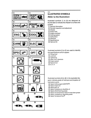
  • 1. ® @ ICHAsld' ------- ® ISPECI er I IOPT I0 I @~@~ @~ ®~ 1 m 1 B 1. a@ __B* OE031 ILLUSTRATED SYMBOLS (Refer to the illustration) Illustrated symbols CD to @> are designed as thumb tabs to indicate the chapter's number and content. CD General information <ID Periodic inspection and adjustment @ Chassis @ Power train <ID Engine overhaul ® Cooling system en Carburetion ® Electrical ® Specifications @> Optional kit Illustrated symbols ® to ® are used to identify the specifications which appear. ® Filling fluid @ Lubricant @ Tightening ® Wear limit, clearance @ Engine speed @) Special tool ®n,V,A Illustrated symbols @) to @ in the exploded dia- gram indicate grade of lubricant and location of lubrication point. @) Apply locking agent (LOCTITE®) @) Apply engine oil @ Apply gear oil @ Apply molybdenum disulfide oil @ Apply wheel bearing grease @ Apply low-temperature lithium-soap base grease @ Apply molybdenum disulfide grease @ Apply Yamabond No.5®
  • 2. INDEX GENERAL INFORMATION PERIODIC INSPECTION AND ADJUSTMENT CHASSIS POWER TRAIN ENGINE OVERHAUL COOLING SYSTEM CARBURETION ELECTRICAL SPECIFICATIONS OPTIONAL KIT CHAS SPEC OPT
  • 3. ______________________________~~~IJieI CHAPTER 1. GENERAL INFORMATION MACHINE IDENTIFICATION ............................. 1-1 FRAME SERIAL NUMBER .......................... 1-1 ENGINE SERIAL NUMBER ......................... 1-1 IMPORTANT INFORMATION ............................ 1-2 PREPARATION FOR REMOVAL AND DIS- ASSEMBLY .................................................. 1-2 ALL REPLACEMENT PARTS ....................... 1-3 GASKETS, OIL SEALS, AND O-RINGS ...... 1-3 LOCK WASHERS/PLATES AND COTTER PINS .............................................................1-3 BEARINGS AND OIL SEALS ....................... 1-3 CIRCLlPS ......................................................1-4 SPECIAL TOOLS ................................................ 1-4 FOR TUNE UP .............................................1-4 FOR ENGINE SERVICE ................................ 1-5 FOR POWER TRAIN SERVICE .................... 1-6 FOR ELECTRICAL SERVICE ........................ 1-7
  • 4. MACHINE IDENTIFICATION II~~~l-:AsI 1-1 lEOOl GENERAL INFORMATION MACHINE IDENTIFICATION FRAME SERIAL NUMBER The frame serial number CD is located on the· right-hand side of the frame (just below the front of the seat). ENGINE SERIAL NUMBER The engine serial number CD is located on the right-hand side of the crankcase. NOTE: _______________________ The first three digits of these numbers are for model identification; the remaining digits are the unit production number. Starting Serial Number: VX500U ......•. SAB-000101 .. VX500EU ..•...SBp·000101.. VX500STU ....SBN·000101 .. VX500DXU ... SBB·000101.. VX600U ........8CA·0001 01.. VX600EU ......SCF·000101.. VX600STU ....SCC·000101 .. VX600DXU ...SCB·000101 .. NOTE: _________________________ Designs and specifications are subject to change without notice.
  • 5. IMPORTANT INFORMATION 1~~~1......1 1-2 lEOll IMPORTANT INFORMATION PREPARATION FOR REMOVAL AND DIS- ASSEMBLY 1. Remove all dirt, mud, dust, and foreign material before removal and disassembly. While cleaning, take care to protect the electrical parts, such as relays, switches, motor, resistors, controllers, etc., from high pressure water splashes. 2. Use proper tools and cleaning equipment. Refer to SPECIAL TOOLS . 3. When disassemblingthe machine, keep mated parts together. This includes gears, cylinders, pistons, and other parts that have been mated through normal wear. Mated parts must be reused as an assembly or replaced. 4. During disassembly ofthe machine, clean all parts and place them in trays in the order of disassembly. This will speed up assembly time and help ensure that all parts are rein- stalled correctly. 5. Keep away from fire. 6. Be sure to keep to tightening torque specifi- cations. When tightening bolts, nuts, and screws, start with larger-diameter pieces, and proceed from an inner-positioned one to an outer-positioned one in a criss-cross pattern.
  • 6. IMPORTANT INFORMATION 1~~~1.1LI 300-000 300-002 300-003 '-3 ALL REPLACEMENT PARTS 1.We recommend use ofYamaha genuine parts for all replacements. Use oil and/or grease recommended by Yamaha for assembly and adjustment. GASKETS, OIL SEALS, AND O-RINGS 1. All gaskets, seals, and a-rings should be re- placed when an engine is overhauled. All gasket surfaces, oil seal lips, and a-rings must be cleaned. 2. Properly oil all mating parts and bearings during reassembly. Apply grease to the oil seal lips. LOCK WASHERS/PLATES AND COTTER PINS 1. All lock washers/plates CD and cotter pins must be replaced when they are removed. Lock tab(s) should be bent along the bolt or nut flat(s) after the bolt or nut has been prop- erly tightened. BEARINGS AND OIL SEALS 1.lnstall the bearing(s) CD and oil seal(s) ® with their manufacturer's marks or numbers facing outwards. (In other words, the stamped letters must be on the side exposed to view.) When installing oil.seal(s), apply a light coating of lightweight lithium base grease to the seal lip(s). Oil the bearings liberally when installing. Do not use compressed air to spin the bearings dry. This causes damage to the surface of the bearings.
  • 7. IMPORTANT INFORMATION/SPECIAL TOOLS I~~~I~I 300·001 1-4 CIRCLlPS 1. All circlips should be inspected carefully be- fore reassembly. Always replace piston pin clips after one use. Replace misshapen circlips. When installing acirclip D, make sure that the sharp edged corner ® is positioned opposite to the thrust ID it receives. See the sectional view. @ Shaft lE021 SPECIAL TOOLS Some special tools are necessary for completely accurate tune-up and assembly. Using the correct special tool will help prevent damage that can be caused by the use ofimpropertools or improvised techniques. NOTE: _______________________ Be sure to use the correct part number when ordering the tool, since the part number differs according to the area as shown below. The first part number is for Europe, and the second part is for the U.S.A. and Canada. e.g. 90890 - *****, YU- ***** FORTUNE UP • Sheave Gauge PIN YS-91047-3 D, YS-39506-5 ® This gauge is used to measure sheave distance and for offset adjustment. lE041 • Dial Gauge PIN 90890-03097, YU-03097 This gauge is used for run out measurement.
  • 8. 1-5 SPECIAL TOOLS I~~~I~IlE051 • Fuel Level Gauge PIN 90890-01312, YM-01312-A This gauge is used to measure the fuel level in the float chamber. lE061 • Vacuum Gauge PIN -, YS-33275 This gauge is used for carburetor synchroniza- tion. 1E071 FOR ENGINE SERVICE • Piston Pin Puller PIN 90890-01304, YU-01304 This tool is used to remove the piston pin. lE081 • Rotor Puller PIN 90890-01362, YU-33270 This tool is used to remove the magneto rotor. lE091 • Cooling System Tester PIN 90890-01325, YS-22460-01 This tester is used for checking cooling system.
  • 9. '-6 SPECIAL TOOLS II~~~I~IlEl0l FOR POWER TRAIN SERVICE • Primary Sheave Holder PIN 90890-01701, YS-01880 This tool is used to hold the primary sheave. lElll • Primary Sheave Puller (18 mm) PIN YS-01881-1 CD, YS-38517 CV Thistool is used for removing the primary sheave. lE121 • Clutch Spider Separator PIN 90890-01711, YS-28890-8 This tools are used when disassembling and as- sembling the primary sheave. lE131 • Clutch Separator Adapter PIN 90890-01740, YS-34480 This tool is used when disassembling and assem- bling the primary sheave. lE171 • Clutch busing jig kit PIN YS-39752 Thistool is used when removing and installing the primary sheave busing.
  • 10. 1-7 SPECIAL TOOLS II~~~ISsI 1E141 • Track Clip Installer PIN 90890-01721. YS-91045-A This tool is used for installing the track clip. 1E151 FOR ELECTRICAL SERVICE • Pocket Tester PIN 90890-03112. YU-03112 This instrument is necessary for checking the electrical components. 1E161 • Electra Tester PIN 90890-03021. YU-33260-A This instrument is invaluable for checking the electrical system.
  • 11. __________I':g!I-.1 CHAPTER 2. PERIODIC INSPECTIONS AND ADJUSTMENTS INTRODUCTION ................................................2-1 PERIODIC MAINTENANCE TABLE ................... 2-1 ENGINE .....................................................•........2-3 SPARK PLUG ...............................................2-3 OIL PUMP ....................................................2-4 OIL FILTER INSPECTION ..........................•.2-6 FUEL LINE INSPECTION .............................2-6 FUEL FILTER INSPECTION ..............•..........2-6 COOLING SYSTEM ............................•.....•.•2-7 CARBURETOR SYNCHRONIZATION •••.... 2-12 ENGINE IDLE SPEED ADJUSTMENT •..... 2-13 THROTTLE CABLE ADJUSTMENT .......••• 2-13 THROTTLE OVERRIDE SYSTEM (T.O.R.S.) CHECK ............................................•.•......2-14 STARTER (CHOKE) CABLE ADJUSTMENT ........................................2-14 POWER TRAIN .................................................2-15 DRIVE V-BELT............................................2-15 ENGAGEMENT SPEED CHECK ................2-17 BRAKE ADJUSTMENT .................................... 2-18 BRAKE PAD INSPECTION ........................ 2-18 DRIVE CHAIN .............................................2-18 TRACK TENSION ADJUSTMENT ............ 2-20 SLIDE RUNNER INSPECTION .................. 2-21 CHASSIS ..........................................................2-22 SKI/SKI RUNNER .......................................2-22 STEERING SYSTEM ..................................2-22 HEADLIGHT BEAM ADJUSTMENT .........2-23 LUBRICATION ...........................................2-24 TUNING ............................................................2-25 CARBURETOR TUNING ............................2-25 CLUTCH TUNING ......................................2-36 GEARING SELECTION ..............................2-38 HIGH ALTITUDE TUNING ...............................2-41
  • 12. INTRODUCTION/PERIODIC MAINTENANCE TABLE I':g~I_I2EOO5 PERIODIC INSPECTIONS AND ADJUSTMENTS INTRODUCTION This chapter includes all information necessary to perform recommended inspections and adjustments. These preventive maintenance procedures, iffollowed, will ensure more reliable machine operation and a longer service life. In addition, the need for costly overhaul work will be greatly reduced. This information applies to machines already in service as well as new machines that are being prepared for sale. All service technicians should be familiar with this entire chapter. PERIODIC MAINTENANCE TABLE First Every Pre- Month Season Item Remarks operation or or check first 800 km 3,200 km (Daily) (500 Mi) (2,000 Mi) (40 hr) (160 hr) Spark Plug: Check condition adjust the gap and clean. •Replace if necessary. Check oil level. •Engine Oil: *Air bleed the oil pump if necessary. • *Oil Filter: Check condition. •Replace if necessary. Fuel: Check fuel level. •Check condition. *Fuel Filter: Replace if necessary. • *Fuel Line: Check fuel hose for cracks or damage. •Replace if necessary. *Oil Line: Check oil hose for cracks or damage. •Replace if necessary. Check coolant level. •Engine Coolant *Air bleed the cooling system if necessary. •Check throttle lever operation. •Carburetor Whenever operating condition *Adjust the jets. (elevation!temperature) is changed. Check wear and damage. Replace if necessary. •*Water Pump Belt Adjust water pump belt if necessary. • Manual Starter: Check operation and rope damage. •*Replace if necessary. Engine Stop Switch: Check operation •*Repair if necessary. Throttle 9verride System: Check operation. •*Repair if necessary. Check operation. Throttle Lever: *Repair if necessary. • *Exhaust System: Check for leakage. •Retighten or replace gasket if necessary. *Decarbonization: More frequently if necessary. • Drive V-belt Guard: Check cracks, bends or damage. •*Replace if necessary. Drive V-belt: Check wear and damage. Replace if necessary. • Drive Track/Idler Wheels: Check deflection, wear and damage. •*Adjust/replace if necessary. Slide Runner Check wear and damage. •*Replace if necessary. •*: It is recommended that these items be serviced by a Yamaha dealer or other qualified mechanic. 2-1
  • 13. _ _ _ _ _~_ _ _ _ IIANDSJPllo)lPERIODIC MAINTENANCE TABLE _ _~ _ First Every Pre- Month Season Item Remarks operation or or check first 800 km 3,200 km (Daily) (500 Mi) (2,000 Mi) (40 hr) (160 hr) Check operation. •Brake/ *Adjust free play and/or replace pads if neces- Parking Brake sary. •Check oil level. •*Drive Chain Oil Replace. • *Drive Chain: Check deflection. **.Adjust if necessary. Ski/ Check wear and damage. •Ski Runner *Replace if necessary. • Steering System Check operation. •*Adjust toe-out if necessary. • Lights: Check operation. •Replace bulbs if necessary. Check fluid level. •Battery *Check specific gravity and breather pipe opera- tion. •Charge/Correct if necessary. Check engagement and shift speed. •Adjust if necessary. Wheneveroperatingelevation ischanged. *Primary Sheave Check wear and damage. •Replace if necessary. Lubricate with specified grease. •Lubricate with specified grease. •*Secondary Sheave Adjust if necessary. Whenever operating elevation ischanged. *Steering Column Bearing: Lubricate with specified grease. •*Ski and Front Suspension: Lubricate with specified grease. •*Suspension Component: Lubricate with specified grease. •*Brake Cable End and Lubricate with specified grease. •Lever End/ Throttle Check cable damage. Cable End Replace if necessary. • Shroud Latches: Make sure the shroud latches are hooked. • Fittings/Fasteners: Check tightness. •*Repair if necessary. Service Tools/Spare Parts: Check proper placement. •*: It is recommended that these items be serviced by a Yamaha dealer or other qualified mechanic. **: Perform after 1 Month or 80 km (50 Mi) and every 1 Month or 800 km (500 Mi). 2-2
  • 14. _________________________S_M_R_K_PL_U__G p:gSI~1 ®*=::::::::;~I/) 377-000 (·~_J1-)CD..' fi...----~41 2-3 2EOll ENGINE SPARK PLUG 1. Remove: • Spark plug 2. Inspect: • Electrode CD Wear/Damage~Replace. • Insulator color ® 3. Measure: • Plug gap@ Out of specification~Regap. Use wire thickness gauge. Spark plug gap: 0.7 - 0.8 mm (0.028 - 0.032 in) Clean the plug with a spark plug cleaner if necessary. Standard spark plug: BR9ES (NGK) Before installing a spark plug, clean the gasket surface and plug surface. 4. Tighten: • Spark plug Spark plug: 28 Nm (2.8 m • kg, 20 ft • Ib) NOTE: ________________________ Finger-tighten CD the spark plug before torquing ® to specification.
  • 15. _________________________O_I_LP_U_M_P II:g~ltill 2-4 2E021 OIL PUMP Air Bleeding The oil pump and delivery line must be bled on the following occasions: • When any portion of the oil system has been disconnected. • When the machine has been turned on its side. • Whenever the oil tank has been run empty. • During pre-delivery. 1. Remove: • Reservoir tank ill 2. Fill: • Oil tank ill Oil tank capacity: 2.9 L (2.6 Imp qt, 3.1 US qt) Recommended oil: Vamalube 2-cycle oil 3. Loosen the oil tank bolt ®. 4. Place a rag under the oil pump assembly to catch oil. 5. Disconnect: • Oil hose ill 6. Keep the oil running out until air bubbles disappear from the oil hose ill. 7. Connect: • Oil hose ill 8. Disconnect: • Oil delivery hoses ill 9. Feed the uYamalube 2-cycle oil into the oil delivery hoses ill using an oil can ® for com- plete air bleeding. 10. Connect: • Oil delivery hoses ill
  • 16. _________________________O_I_LP_U_M_P II:g!I~1 2-5 11. Remove: • Bleed screw D • Gasket (bleed screw) 12. Keep the oil running out until air bubbles disappear from bleed hole. 13. Inspect: • Gasket (bleed screw) Wear/Damage ~ Replace. 14. Install: • Gasket (bleed screw) • Bleed screw Cable Adjustment NOTE: _________________________ Before adjusting the oil pump cable, the throttle cable distcmce should be adjusted. Adjustment steps: • Loosen the locknut D. • Turn the adjuster® in or out until the speci- fied distance is obtained. ~ Distance® : VX500(E)fSTfOX: 25 - 27 mm (0.98 - 1.06 in) VX600(ElfSTfOX: 27 - 29 mm (1.06 -1.14 in) Turning in Distance ® is increased. Turning out Distance ® is decreased. • Tighten the locknut and push in the adjuster cover.
  • 17. 800-001 801·002 8OHl03 OIL FILTER INSPECTION II:g~ItAI 2-6 2E031 OIL FILTER INSPECTION 1. Remove: • Oil filter CD NOTE: _______________________ Plug the oil hoses so that the oil will not run outof the oil tank and oil pump. 2. Inspect: • Oil filter CD Contamination ~ Replace. Recommended replacement interval: Every season 3. Reverse the removal procedure. 2E041 FUEL LINE INSPECTION 1. Inspect: 2E051 • Fuel hoses • Fuel delivery hoses Crack/Da mage~Replace. FUEL FILTER INSPECTION 1. Remove: • Seat 2. Disconnect: • Tail/brake light coupler 3. Remove: • Spring bands CD • Cap® • Fuel filter @ 4. Inspect: • Fuel filter CD Contamination ~ Replace. Recommended replacement interval: Every season 5. Reverse the removal procedure.
  • 18. COOLING SYSTEM ~ ------------------------------------------------------ IlANOSJP Ito) I 2-7 2E061 COOLING SYSTEM Coolant Replacement NOTE: _______________________ The coolant should be changed at least seasonally. 1. Place the machine on a level surface. 2. Remove: • Side cowling (right) • Seat • Muffler CD • Exhaust pipe ® 3. Remove: • Coolant filler cap CD A WARNING Do not remove the coolant filler cap CD when the engine is hot. Scalding hot fluid and steam may be blown out under pressure, which could cause serious injury. When the engine has cooled, place thick rag like atowel overthe radiator cap, slowly rotate the cap counterclockwise to the detent. This procedure allows any residual pressure to escape. When the hissing sound has stopped, press down on the cap while turning counterclockwise and remove it. 4. Place an open container under the drain bolts CD· S.Remove: • Drain bolts 6. Drain the coolant. NOTE: _________________________ Lift up the tail ofthe machine to drain the coolant.
  • 19. o 2-8 COOLING SYSTEM 1':gS14rl1 7. Disconnect: • Coolant hoses CD (rear) 8. Drain the coolant. NOTE:____________ Liftupthe front ofthe machineto drainthe coolant completely. A WARNING Coolant is poisonous. It is harmful or fatal if swallowed. • Ifcoolantisswallowed, induce vomiting imme- diately. Get immediate medical attention. • If coolant splashes in eyes, flush with water. Call a physician. • If coolant splashes on skin or clothes, wash immediately with soap and water. 9. Remove the reservoir tank CD and drain the coolant. 10. Install: • Reservoir tank 11. Inspect: • Gaskets (drain bolt) Damage~Replace. 12. Install: • Gaskets • Drain bolts • Exhaust pipe/gaskets • Muffler 13. Fill: Drain bolt: 23 Nm (2.3 m· kg, 17 ft· Ib) Bolts (exhaust pipe): 23 Nm (2.3 m • kg, 17 ft· Ib) • Cooling system Recommended Coolant: High quality ethylene glycol anti-freeze containing corrosion inhibitor Coolant and water mixed ratio: SO%: 400/0 Total amount: VX500(E)/VXSOO(E)/VX500DX/ VXSOODX 4.2 L (3.70 Imp qt, 4.44 US qt) VX500ST/VXSOOST 4.S L (4.05 Imp qt, 4.8S US qt) Reservoir tank capacity: 0.2 L (0.18 Imp qt, 0.21 US qt)
  • 20. _ _________ IIANDSJPI ..~ ICOOLING SYSTEM _ _~ _ 2-9 • Hard water or salt water is harmful to the engine parts; use boiled or distilled water. • Do not use water containing impurities or oil. 14. Bleed air from the cooling system. 15. Inspect: • Cooling system Decrease of pressure (leaks)~Repair as re- quired. (see page 6-4) Inspection steps: • Attach the Cooling System Tester D (90890- 01325, YU-22460-01) to the coolant fi lIer ®. • Apply 100 kPa (1.0 kg/cm2, 14 psi). • Measure the pressure with gauge. 2E071 Air bleeding 1. Bleed air from the cooling system. Air bleeding steps: • Lift up the tail of the machine. • Connect plastic tubes D tightly to the bleed screws ® on the heat exchanger. • Loosen the bleed screws ® of Heat ex- changer. • Keep the coolant running out until air bub- bles disappear, while adding coolant slowly to the radiator. • Tighten the bleed screws. ~ Bleed screw: ~ 6 Nm (0.6 m • kg, 4.3 ft • Ib) • Add coolant to fill the specified level ®. • Loosen the bleed bolt @ on the water pump housing. • Keep the coolant running out until air bub- bles disappear. • Tighten the bleed bolt. Bleed bolt: 6 Nm (0.6 m • kg, 4.3 ft • Ib)
  • 21. _ _ _ _ _ _ _ _ _ _ _ 1lANDSJP 1~ ICOOLING SYSTEM . . ~ . 2·10 • Install the radiator cap. Apply and lock the parking brake. Start the engine and run it at approximately 2500 ... 3000 rpm until the thermostat opens and the coolant circulates (approximately 3 ... 5 min- utes). The rear heat exchanger will be warm to the touch. A WARNING To avoid severe injury or death: • Makesurethe machineissecurely supported with a suitable stand. • Do not exceed 3000 rpm. The machine could unexpectedly move forward if the clutch engages, ordrive line damage and excessive V-belt wear could occur. • Operate the engine only in a well-ventilated area. • Remove the radiator cap and bleed air on the cooling system again, as shown in the steps above. No air bubbles ~ OK. • Add coolant up to the specified level. • Pour coolant into the reservoir tank CD until the coolant level reaches HFULLHlevel mark. 2E081 Water Pump Belt Deflection Adjustment 1. Remove: • Muffler 2. Check: • Drive belt deflection Out of specification~Adjust. Drive belt deflection 8 mm (0.31 in)/ 8 kg (17.6Ib) (NEW BELT) 8 mm (0.31 in)/ 13 ... 20 kg (28.7 ... 44.1 Ib) 3. Adjust: • Drive belt deflection Adjustment steps: • Remove the recoil starter CD. • Attach the Primary Sheave Holder (90890- 01701, YS-01880)to hold the primarysheave.
  • 22. 2-11 COOLING SYSTEM II~g!Itll • Remove the starter pulley 0. • Remove the screws @ of the starter pulley. • Adjust the drive belt deflection by adding or removing a shim G). Add shim Tension becomes lower. Remove shim Tension becomes higher. Shim size Part number Thickness 8CA-15721-00 0.5 mm (0.02 in) 8CA-15722-00 1.0 mm (0.04 in) • Install the starter pulley and drive belt. • Recheck the drive belt deflection. If out of specification, readjust the drive belt deflec- tion. 4. Tighten: Starter pulley bolt: 23 Nm (2.3 m· kg, 17 ft· Ib) Recoil starter bolt: 10 Nm (1.0 m • kg, 7.2 ft· Ib)
  • 23. _ _ _ _ _ _ _ _ _ _ liANOSJPlfO) ICARBURETOR SYNCHRONIZATION . . ~ . 2-12 2E094 CARBURETOR SYNCHRONIZATION 1. Remove: • Carburetor assembly (see page 7-2) 2. Adjust: • Carburetor synchronization Adjustment steps: • First adjustthe throttle valve height@ at the No.2 carburetor by turning the throttle stop screw CD until the specified height is ob- tained. I~ Throttle valve height: VX500 (E)/ST/DX: 1.5 mm (0.059 in) VX600 (E)/ST/DX: 1.6 mm (0.063 in) • Second adjust the throttle valve height@on the No.1® carburetor with adjusting eccen- tric nut@. • Move the throttle lever 2 - 3 times. • Make sure all the carburetor throttle valves are on the same height. • Install the carburetor. • Remove the air chamber and then plug the hole in the carburetor joint with plug and connect the Vacuum Gauge (YS-33275) to the fitting. • Start the engine and let it warm up. • If vacuum reading are not same, turn the adjusting eccentric nut@inoroutsothatthe vacuum reading are the same. NOTE: ______________________ When read the vacuum gauge, make sure carburetor covers G) are installed.
  • 24. ENGINE IDLE SPEED ADJUSTMENT/ IINSPI(0) ITHROTTLE CABLE ADJUSTMENT ADJ ~ L...:.':'::;';:;......_';;;:'=..I 2-13 2El0l ENGINE IDLE SPEED ADJUSTMENT 1.Adjust: • Engine idle speed Adjustment steps: • Start the engine and let it warm up. • Turn the throttle stop screws CD in or out to adjust the engine idle speed. Turning in Idle speed becomes higher. Turning out Idle speed becomes lower. Cl Engine idle speed: 1,450 - 1,650 r/min NOTE: After adjusting the engine idle speed, the throttle cable free play should be adjusted. 2E131 THROTTLE CABLE ADJUSTMENT NOTE: _______________________ Before adjusting the throttle cable free play, the engine idle speed should be adjusted. 1. Measure: • Throttle cable free play ® Out of specification~Adjust. Throttle cable free play: 1.0 - 2.0 mm (0.04 - 0.08 in) 2. Adjust: • Throttle cable free play Adjustment steps: • Loosen the locknut CD. • Turn the adjuster ® in or out until the speci- fied free play is obtained. Turning in Free play is increased. Turning out Free play is decreased. • Tighten the locknut.
  • 25. THROTTLE OVERRIDE SYSTEM (T.O.R.S.) CHECKI IINSPI(0) ISTARTER (CHOKE) CABLE ADJUSTMENT ADJ ~ a...:....;;.::;;..;::;~_-=-.=..I ® 2·14 2El22 THROTTLE OVERRIDE SYSTEM (T.O.R.S.) CHECK A WARNING When checking T.O.R.S.: • Be sure the parking brake is applied. • Be sure the throttle lever moves smoothly. • Do not run the engine upto clutch engagement rpm. Otherwise. the machine could start moving forward unexpectedly. which could cause and accident. 1. Start the engine. NOTE: _______________________ Refer to STARTING THE ENGINE. 2. Hold the pivot point ofthe throttle lever away from the throttle switch CD. 3. Press CV the throttle lever gradually. The T.O.R.S warning light should turn on and off and the engine should run between 2800 and 3000 rpm. A WARNING Ifthe engine does not run between 2800 and 3000 rpm. stop the engine by turning the main switch to OFF position and consult a Yamaha dealer. 2E131 STARTER (CHOKE) CABLE ADJUSTMENT 1. Pull the outer tube of starter cable CD upward. 2. Measure: • Starter cable free play ® Out of specification -7 Adjust. Freeplay@: 0.5 .. 1.5 mm (0.02 .. 0.06 in) 3. Adjust: • Starter cable free play Adjustment steps: • Loosen the locknut CD. • Turn the adjuster CV in or out until the speci- fied free play is obtained. Turning in Free play is increased. Turning out Free play is decreased. • Tighten the locknut and push in the adjuster cover.
  • 26. ________________________D_R_IV_E_V_-B_El__T p:gSI~1 2E141 POWER TRAIN DRIVE V-BELT A WARNING • Be sure there are shims (2 pes) CD between secondary fixed and sliding sheaves when· installing the NEW belt. 805030 • Ifthere is no gap, the clutch engagement speed L-_ _ _ _ _ _....;;;~;;..-._ _ _ _ _ _..... will be reduced. The machine may move 805-029 805-020 2-15 unexpectedly when the engine is started. • The spacer of the secondary sheave should be adjusted. To ensure proper clutch performance, the spacers in the secondary clutch must be repositioned as the V-belt wears. V-belt width CD Number of spacers ~ 31.6 mm (1.24 in) or more 2 spacers 00.l 30.6 mm (1.20 in) 1 spacer [9 29.6 mm (1.17 in) No spacer 28 mm (1.1 in) or less Replace the V-belt 1. Remove: • Drive V-belt guard CD
  • 27. ________________________D_R_IV_E_V_-B_El___• P:g!I~1 805-009 2-16 2. Remove: • Drive V-belt CD Removal steps: • Rotate the secondary sliding sheave clock- wise ® and push it @ so that it separates from the fixed sheave. • Pull @ the belt up over the secondary fixed sheave. • Remove the belt from the secondary sheave and primary sheave. 3. Inspect: • Drive V-belt CrackJWear/Damage ~ Replace. Oil orgrease adhering tothe V-belt ~ Check the primary and secondary sheaves. 4. Inspect: • Primary sheave • Secondary sheave Oil or grease adhering to the primary and secondary sheaves ~ Remove the oil or grease using a rag soaked in lacquerthinner or solvent. Check the primary and secon- dary sheaves. 5. Measure: • Drive V-belt length ® Out of specification ~ Replace. Drive V-belt length: 1,130 - 1,118 mm (44.5 - 44.0 in)
  • 28. ENGAGEMENT SPEED CHECK I':gsI_I 2-17 2E201 ENGAGEMENT SPEED CHECK 1. Place the machine on a level area of hard packed snow. 2. Check: • Clutch engagement speed Checking steps: • Start the engine, and open the throttle lever gradually. • Check the engine speed when the machine starts moving forward. Out of specification ~ Adjust the primary sheave. (see page 2-36) C) Engagement speed: VX500(E)fSTfDX Approx. 3,700 rfmin VX600(E)fSTfDX Approx. 3,600 rfmin
  • 29. ® ~I I I I I I I I I _J BRAKE PAD INSPECTION/DRIVE CHAIN II~gjI_I 2-18 2E161 BRAKE ADJUSTMENT BRAKE PAD INSPECTION 1. Apply the brake lever. 2. Measure: • Brake pad thickness ® Out of specification ~ Replace brake pads as a set. (see page 4-27) I~ Wear limit: v ~ 5.2 mm (0.2 in) NOTE: _________________________ Adjust brake every 40 hours of operation, or whenever the brake lever becomes loose during operation. 3. Measure: • Distance L Out of specification --) Adjust. Distance ULU 69.0 ~ 71.0 mm (2.72 ~ 2.8 in) 4. Adjust: • Distance L Adjustment steps: • Loosen the locknut CD. • Turn the adjuster CV in or out until the speci- fied distance is obtained. Turning in Distance uLu is increased. Turning out DistanceuLU is decreased. • Tighten the locknut CD. 2E171 DRIVE CHAIN Oil Level Inspection 1. Place the machine on a level surface. 2. Remove: • Muffler 3. Place a rag under the checking hole CD (oil level). 4. Remove: • Checking bolt CV • Gasket (checking bolt)
  • 30. _____________D_RI_VE_C_H_A_IN p:gjI_I 2-19 5. Inspect: • Oil level (drive chain housing) Oil flows out ~ Oil level is correct. Oil does not flow out ~ Oil level is low. Add oil until oil flows out. Recommended oil: Gear oil API GL-3 SAE #75 or #80 6. Inspect: • Gasket (checking bolt) Damage ~ Replace. 7. Tighten: Checking bolt: 10 Nm (1.0 m· kg, 7.2 ft· Ib) Oil Replacement Oil replacement step: • Warm up the engine for several minutes. • Remove the Muffler. • Place some rags under the chain housing and place a small gutter to channel the oil into the hole. • Lift up the front of the machine. • Remove the drain plug CD. Be sure to remove any oil from the heat protec- tor. 2E182 Recommended oil: Gear oil API GL-3 SAE #75 or #80 Oil capacity: VX500 (E)/500ST/600(E)/600ST: 250 cm3 (8.8 Imp OZ, 8.5 US OZ) VX500DX/600DX: 300 cm3 (10.6 Imp OZ, 10.1 US OZ) Chain Slack Adjustment 1. Adjust: • Drive chain slack Adjustment steps: • Loosen the locknut CD and unthread sealing washer CV slightly. • Turn the adjuster @ in until it is finger tight. • Tighten the locknut.
  • 31. CD ...® TRACK TENSION ADJUSTMENT I':gsI_I 820003 820-004 2-20 2E151 TRACK TENSION ADJUSTMENT A WARNING A broken track, track fittings, or debris thrown by the track could be dangerous to an operator or bystanders. Observe the following precautions. • Do not allow anyone to stand behind the machine when the engine is running. • When the rear of the machine is raised to allow the track to spin, a suitable stand must be used to support the rear ofthe machine. Never allow anyone to hold the rear of the machine off the ground to allow the track to spin. Never allow anyone near a rotating track. • Inspect track condition frequently. Replace the track if it is damaged to the depth where fabric reinforcement material is visible. • Never install studs (cleats) closer than three inches to the edge of the track. 1. Place the machine with the right side facing down. 2. Measure: • Track deflection CD Pull at the track center window exerting a force of 10 kg (22 Ib) using a spring scale 0. Out of specification ~ Adjust. Track deflection: 25 .. 30 mm (0.98 .. 1.18 in) 3. Adjust: • Track deflection Adjustment steps: • Lift the rear of the machine onto a suitable stand to raise the track off the ground. • Loosen the rear axle nut CD. NOTE: ____________ It is not necessary to remove the cotter pin 0.
  • 32. TRACK TENSION ADJUSTMENT! IINSPIto) ISLIDE RUNNER INSPECTION ADJ ~ L...:.,':'=;':.L--=.=...I 820-008 820-005 @+ 820009 ~ ~ ~..... _ _ _ _ _ _ _ .J 820-001 a. Starttheengine and rotate the track one or two turns. Stop the engine. b. Check the track alignment with the slide runner CID. If the alignment is incorrect. turn the left and right adjusters to adjust. Track alignment @ Shifted (j) Shifted to right to left @ Left adjuster Turn out Turn in CID Right adjuster Turn in Turn out ® Slide runner ® Track @ Track metal ® Gap @ Forward c. Adjust track deflection to the specified amount. Track deflection More than Less than specified specified @ Left adjuster Turn in Turn out CID Right adjuster Turn in Turn out The adjusters should be turned an equal amount. • Recheck alignment and deflection. If neces- sary, repeat steps a to c until proper adjust- ment is achieved. • Tighten the rear axle nut. Rear axle nut: 75 Nm (7.5 m • kg, 54 ft· Ib) SLIDE RUNNER INSPECTION 1. Inspect: • Slide runner CD Cracks/DamageMlear~Replace. 2. Measure: • Slide runner thickness CV Out of specification~Replace. (see page 4-33) ~ W~~!:~:03::,_n_)______--J
  • 33. IlANDSJP Ito) ISKI/SKI RUNNER/STEERING SYSTEM ~ ------------------------------------------------------ 2·22 2E212 CHASSIS SKI/SKI RUNNER 1. Check: • Ski • Ski runner • Ski cover Wear/Damage ~ Replace. Ski runner wear limit G): 8 mm (0.31 in) Do not operate the machine without the ski cover to prevent ski wear and damage. 2E221 STEERING SYSTEM Free Play check 1. Check: • Steering system free play Push the handlebar up and down and back and forth. Turn the handlebar slightly to the right and left. Excessive free play ~ check to be sure the handlebar, tie rod ends and relay rod ends are installed securely in position.lffree play still exists, check the steering bearing front suspension links and ski mounting area for wear, and replace if necessary. (see page 3-9)
  • 34. IlANDSJP. I(0) ISTEERING SYSTEM/HEADLIGHT BEAM ADJUSTMENT ~ ------------------------------------------------------ 2-23 2E232 Toe-Out Adjustment 1. Place the machine on a level surface. 2. Check: • Ski toe-out Direct the skis straight forward. Out of specification~Adjust. Ski toe - out (@ - @): 0.0 .. 15.0 mm (0.0 .. 0.6 in) Ski stance (6) (center to center): 1,010 mm (39.8 in) 3. Adjust: • Ski toe-out Adjustment steps: • Loosen the locknuts CD (tie-rod). • Turn the relay rod ® in or out until the specified toe-out is obtained. • Tighten the locknuts CD (tie-rod). Locknut (rod end): X 25 Nm (2.5 m· kg, 18 ft· Ib) LOCTITE® ~ Left side [§] Right side 2E241 HEADLIGHT BEAM ADJUSTMENT 1. Place the machine on a level surface. 2. Inspect: • Headlight beam direction L H The high beam should be directed down- wards at an angle of 1/20 to the horizontal. If not, adjust the direction. 3.0 m (10 ft) 7.6 m (25 ft) 26 mm (1.0 in) 66 mm (2.6 in) 3. Adjust: • Headlight beam direction Adjust the headlight beam by tightening or loosening the adjusters CD.
  • 35. LUBRICATION ~ ------------------------------------------------------ IlANOSJP Ito) I A 2-24 2E251 LUBRICATION Brake Lever, Brake Cable End and Throttle Lever 1. Lubricate the brake lever pivot. brake cable end and throttle lever. I_IESSO Beacon 325 Grease A WARNING Apply a dab of grease to the cable end only. Do not grease the brake/throttle cables themselves because they could become frozen, which could cause loss of control. 2E261 Front and Rear ~uspension 1.lnjectgreasethrough nipplesG) using agrease gun. --.. Esso Beacon 325 Grease or Aeroshell Grease #7A. g] Front [ID Rear
  • 36. IlANDSJP I~ ICARBURETOR TUNI~G ~ ----------------------------------------------- 2·25 2E271 TUNING CARBURETOR TUNING The carburetor is set at the factory to run at temperatures of O°C .. -20°C (32°F .. -4°F) at sea level. If the machine has to be operated underconditions otherthanthosespecified above, . the carburetor must be reset as required. Special care should be taken in carburetor setting so that the piston will not be damaged or seized. In this model, the engine oil is mixed with the fuel just before the fuel enters the carburetors. During initial fuel flow to the carburetor it is not always possible to supply the optimum fuel/oil mixture depending on the throttle opening. Therefore, afterthe carburetors have been tuned or maintained, or after the float chamber is removed for cleaning or jet replacement, be sure to idle the engine for about three minutes in order to avoid engine trouble. Before performing the carburetor tuning, make sure that the following items are set to specification. • Engine idle speed adjustment • Throttle cable free play adjustment • Carburetor synchronization • Starter cable adjustment • Oil pump cable free play adjustment Carburetor Tuning Data 1. Standard specifications MODEL VX5OO(E)/ST/DX VX600(EIIST/DX Type TM36-B2S TM3S-B103 Manufacturer MIKUNI ~ 1.0. Mark SAB-OO aeA-OO Main jet (M.J.) #151.3 #156.3 Pilot jet (P.J.) #45 #52.5 Pilot air jet 02.5 ~ (P.A.J.) Pilot screw 1-1/S ~ (P.S.) turns out Float height 20.3 .. 24.3 mm (0.799..0.957 in) ~ Idle speed 1,450..1,60rIm +-
  • 37. .- CARBURETOR TUNING II:gsI_I 2-26 2E281 Middle-Range and High Speed Tuning No adjustment is normally required, but adjust- ments may sometimes be necessary, depending on temperatures and/or altitude. Middle-range speed and high speed tuning (from 1/4 to full-throttle) can be done by adjusting the main jet. The engine should never be run without the air intake silencer and air chamber installed; severe engine damage may result. 1. Start the engine and operate the machine under normal conditions to make sure the engine operates smoothly. Then stop the en- gine. 2. Remove: • Spark plugs 3. Check: • Spark plug insulator CD color A medium to light tan color indicates nor- mal conditions. Distinctly different color ~ Replace main jet. 4. The main jet should be adjusted on the basis of the following HMain jet selection chart. NOTE: ________________________ By checking the condition of the spark plugs currently being used, itiseasyto get some idea of the engine condition and catch potential problems before they are too far advanced.
  • 38. IlANDSJP Ito) ICARBURETOR TUNING ~ ----------------------------------------------- FOR VX500 (E)/ST/DX ~[ID Altitude 0- 100 m (0 - 300 ft) 100 - 600 m (300 - 2,000 ft) 600 - 1,200 m (2,000 - 4,000 ft) 1,200 - 1,800 m (4,000 - 6,000 ft) 1,800 - 2,400 m (6,000 - 8,000 ft) 2,400 - 3,000 m (8,000 - 10,000 ft) -30oe (-22°F) I MJ #156.3 MJ #153.8 MJ #151.3 -20oe (-4°F) I ..~ 2E291 2. High altitude tuning Use the following guide to select main jets according to variations in elevation and tem- perature. -10oe ooe 100 e 200 e (14°F) (32°F) (50°F) (68°F) I I I I MJ #153.8 ~ ... MJ #151.3 ....-..MJ #151.3 (STO)----.. ~ ... MJ #148.8 IN:2 .....- MJ #148.8 IN:2 ---. ~ .. MJ #146.3 IN:2 ....-.. MJ #146.3 IN:2 ----. r--MJ #148.8JN:2--. .. MJ #143.8 IN:2 .... MJ #143.8 IN:2 .... f---MJ #146.3 IN:2--' .. ...-MJ #140 IN:2----.. PJ #50 AS:3/4 r----MJ #143.8 IN:2--. .. 2-27 MJ #140 IN:2 MJ #137.5 IN:2 PJ #50 AS:3/4 [9 # : Main jet number [Q] IN: Jet needle clip position WAS: Air screw turns out [£] PJ : Pilot jet number
  • 39. FOR VX600 (E)/ST/DX ~[ID Altitude 0- 100 m (0 - 300 ft) 100 - 600 m (300 - 2,000 ft) 600 - 1,200 m (2,000 - 4,000 ft) 1,200 - 1,800 m (4,000 - 6,000 ft) 1,800 - 2,400 m (6,000 - 8,000 ft) 2,400 - 3,000 m (8,000 - 10,000 ft) CARBURETOR TUNING I':gj1-.1 -30°C -20°C -10°C O°C 10°C 20°C (-22°F) (-4°F) (14°F) (32°F) (50°F) (68°F) 1 I ... MJ #160 ..MJ #162.5 .. ... MJ #157.5 ...--MJ #156.3 (STD)----. MJ #158.8 .. ... MJ #153.8 IN:2 ...-- MJ #153.8 IN:2----' MJ #156.3 .. ... MJ #151.3 IN:2 ...-- MJ #151.3 IN:2----. -MJ #153.8 IN:2---. ... MJ #148.8 IN:2 ...-- MJ #148.8 IN:2----. - MJ #151.3 IN:2--' ...-- -MJ #147.5 IN:2--' MJ #145 IN:2 ... MJ #145 IN:2 ----. ... MJ #142.5 AS:7/8 IN:2 [g # : Main jet number [QJ IN: Jet needle clip position [[] AS: Air screw turns out [.EJ PJ : Pilot jet number NOTE: ________________________ These jetting specifications are subjectto change. Consult the latest technical information from Yamaha to be sure you have the most up-to-date jetting specifications. CD Clip ® Jet needle @ Air screw G) Main jet 2-28
  • 40. CARBURETOR TUNING I':g~I_I2E302 Guide for carburetion (A] Throttle valve opening [ID Mid-range speed tuning ® ® CD [EJ Low speed tuning CID ® @ CID 1... :E.... [El Closed 1/8 1/4 1/2 3/4 [QJ Full open (A] Throttle valve opening 2-29
  • 41. _ _ _ _ _ _ _ _ _ _ 1lANOSJP 1**1CARBURETOR TUNING _ _~ _ 1/8 A: Standard main jet B: Main jet whose diameter is 10010 smaller than standard C: Main jet whose diameter is 10010 larger than standard 1/2 3/4 © Full open [ID Throttle opning A: No_ 3 position B: No. 2 position C: No. 4 position ir]Clip [El Jet needle 1/2 3/4 ©Full open [ID Throttle opening 2-30 If the Air Silencer Box is removed from the carburetors, the change in pressure in the intake will create a LEAN MIXTURE that may well cause severe engine damage. The Air Silencer Box has no effect on performance characteristics and must be secured to the carburetor during carburetor tuning and adjustment. Also, it must always be in place when the engine is operated. Examine the Silencer regularly for cleanliness and freedom from obstruction.
  • 42. IlANOSJP I(0) ICARBURETOR TUNING ~ --------------------------------------~-------------- 2·31 2E391 Low Speed Tuning The carburetor is built so that low speed tuning can bedone byadjustingtheairscrewandthrottle stop screw CD. The engine should never be run without the air intake silencer and air chamber installed; severe engine damage may result. 1. Tighten the air screw lightly, and back it out from its lightly seated position. Standard tuning out: 1-1/8 2. Start the engine, and allow it to warm up for a few minutes. The warm-up is complete when the engine responds normally to the throttle opening. A WARNING Do not move the throttle enough to reach the following engagement speed. The snowmobile could accidentally start to move forward. Engine revolutions: 2,600 r/min 3. Adjustthethrottle stop screws evenly untilthe engine speed is at 2,000 - 2,500 r/min. 4. Slowly loosen the pilot screws evenly. As the pilot screw is loosened, the mixture will be come leaner, and engine speed will increase. Adjust the pilot screws to attain the highest possible engine speed.
  • 43. CARBURETOR TUNING II:g!.I_1 2-32 5. Finally, setthe engine idle speed bytuning the throttle stop screws in (to increase engine speed) or out (to decrease engine speed). Standard idle speed: 1,450 .. 1,650 rfmin 6. If the engine low speed performance is still poor in high elevation under extreme condi- tions, the standard pilot jets may need to be replaced to obtain proper pilot air/fuel mix- ture. NOTE: ________________________ In this case, set the carburetor on the richer side; use a larger number pilot jet with a highes number. Standard pilot jet: VX500(E)fSTfOX: #45 VX600(E)fSTfOX: #52.5 7. By repeating steps 1to 5above, adjustthe idle speed.
  • 44. IlANDSJP I'~ ICARBURETOR TUNING ~ ------------------------------------------------------2E311 Main jet selection chart Spark plug color Check up Remedy Light tan or gray. Carburetor is tuned properly. Dry black or fluffy Mixture is too rich. Replace main jet with the next smaller size.deposits. White or light gray. Mixture is too lean. Replace main jet with the next larger size. White or gray insulator with small black or gray Due to too lean a mixture, the Replace the piston and spark plug. brown spots and Tune the carburetor again, starting with low- electrodes having a piston is damaged or seized. speed tuning. bluish-burnt appearance. Melted electrodes and Check the piston for holes or seizure. possibly blistered Check the cooling system, gasoline octane rating insulator. Due to too lean a mixture, the and ignition timing. After replacing the spark plug Metallic deposits on spark plug melts. with a colder type, tune the carburetor again insulator. starting with low-speed tuning. 2-33
  • 45. __________IIANOSJPI·ollCARBURETOR TUNING . . ~ . 2E321 Troubleshooting Trouble Hard starting Poor idling (Related troubles) • Poor performance at low speeds • Poor acceleration • Slow response to throttle • Engine tends to stall Poor performance at mid-range speeds (Related troubles) • Momentary slow response to throttle • Poor acceleration Poor performance at normal speeds (Related troubles) • Excess fuel con- sumption • Poor acceleration Check point Insufficient fuel Excessive use of starter (Excessively opened choke) Fuel passage is clogged or frozen Overflow Improper idling speed adjustment • Pilot screw • Throttle stop screw Damaged pilot screw Clogged bypass hole Clogged or loose pilot jet Air leaking into carbu- retor joint Defective starter valve seat Overflow Clogged or loose pilot jet Lean mixtures Clogged air vent Clogged or loose main jet Overflow Remedy Adjustment Add gasoline Clean spark plug Return starter level to its seated position. Clean Parts otherthan aircarburetor. • Clogged fuel tank air vent, clogged fuel filter, or clogged fuel passage. Carburetor • Clogged or frozen air vent, or clogged valve. • If water collects in float chamber, clean. (Also check for ice) Correct Bottom the pilot screw lightly, and back it outto specification. Adjust idling speed Start the engine and turn pilot screw in and out 1/4 turn each time. When the engine runs faster, back out throttle stop screw so the engine idles at specified speed. Tightened too much - Engine speed is higher. Adjust Backed out too much - Engine does not idle. Replace pilot screw Clean Clean and retighten Remove pilot jet, and blow it out with compressed air. Retighten bend screw Clean or replace Correct Clean and retighten Remove pilot jet, and blow it out with compressed air. Overhaul carburetor Clean Remove the air vent pipe, and clean. Clean and retighten Remove main jet, and blow it out with compressed air. Check float and float valve and clean 2·34
  • 46. CARBURETOR TUNING I':gs1_I Trouble Check point Remedy Adjustment Poor performance at Starter valve is left Fully close valve Return starter lever to its high speeds open home position. (Related troubles) Clogged air vent Remove and clean • Power loss • Poor acceleration Clogged or loose main Clean and retighten Remove main jet and clean jet with compressed air, then install. Clogged fuel pipe Clean or replace Dirty fuel tank Clean fuel tank Air leaking into fuel Check joint and re- line tighten Low fuel pump per- Repair pump or re- formance place Clogged fuel filter Replace Clogged intake Check for and remove ice Abnormal combus- Lean mixtures Clean carburetor tion and adjust (Mainly backfire) Dirty carburetor Clean carburetor Dirty or clogged fuel Clean or replace fuel pipe pipe Overflow Clogged air vent Clean (Related troubles) Clogged float valve Disassemble and Clean while taking care not to • Power idling clean scratch valve seat. • Poor performance Scratched or unevenly Clean Valve seat is press'fitted toat low, mid-range, or replace and high speeds worn float valve or float valve and valve body. • Excessive fuel valve seat seat The body must be replaced if consumption seat is damaged. • Hard starting Broken float Replace float • Power loss Incorrect float level If not within the • Poor acceleration specified range, check the following parts and replace any defective part. • Worn float tang • Replace float Replace float assembly. • Worn pin • Replace arm pin • Deformed float arm • Replace float 2-35
  • 47. _ _ _ _ _ _ _ _ _ _ 1lANDSJP 1(0) ICLUTCH TUNING _ _~ _ Clutch Setting Data (VX500(E)fSTfOX) @ltem 0-1,000 m 3,500 ft (STD) rnJ Idle speed: Approx. 1,550rpm [g Clutch engagement: Approx. 3,700rpm [Q] Shift speed: Approx. 7,S50rpm ~ Geering: 20139 [f] Primary spring: [Q] Color W-P-W [BJ Length 78.7mm 0] Pre-Ioad rate 30.0kg-2.25 kg/mm Q] Wiredia. 05.5mm 00 Outside dia. 0S0mm [jJ Weight: 8AV-17605-10 IMI Weight rivet: Steel 13.3mm [ID Weight bush: Duralon IQ] Roller bush: Duralon (f] Pri. clutch shim: None IQ] Secondary spring: [Q] Color P [BJ Length 85mm 0] Pre-Ioad rate 600(B-2) Q] Wiredia. 05.0mm 00 Outer dia. 0S5mm [B] Sec. torque cam: 390 [§] Sec. clutch shim: None CLUTCH TUNING High Altitude Tuning 900 - 1,500 m 1,400 - 2,100 m 3,000 - 5,000 ft 4,500 - 7,000 ft (MA) (MA) +- +- +- +- +- +- +- 19139 +- +- +- +- +- +- +- +- +- +- +- +- Aluminum 10.3mm None +- +- +- +- +- +- +- +- +- +- +- +- +- +- +- +- +- +- +- +- 2-36 2,000 m- S,500 ft- (HA) +- +- +- 18/39 +- +- +- +- +- +- Aluminum 10.3mm +- +- +- +- +- 500 (A-2) +- +- 360 +- W ...............White P ................... Pink
  • 48. Clutch Setting Data (VX600(E)/DX) ~Item o~ 1,000 m 3,500 ft (STD) lID Idle speed: Approx. 1,550rpm [g Clutch engagement: Approx. 3,600rpm rnl Shift speed: Approx. 7,650rpm [g] Geering: 20/37 !El Primary spring: IQ] Color L·Y·L IBl Length 78.0mm ill Pre-Ioad rate 25.0kg·2.Okgfmm III Wiredia. 8S.5mm 00 Outside dia. 860mm ~Weight: 8AY-17605-10 IMI Weight rivet: Steel 17.2mm 1Nl Weight bush: Duralon [Q] Roller bush: Duralon If] Pri. clutch shim: 1.0 mm x 2pcs. IQJ Secondary spring: IQ] Color P IBl Length 85mm ill Pre-Ioad rate 500 (A-2) III Wiredia. fl5.0mm 00 Outer dia. fl65mm lID Sec. torque cam: 390 rru Sec. clutch shim: None (VX600ST) o~ 1,000 m ~Item 3,500 ft (STD) lID Idle speed: Approx. 1,550rpm [g Clutch engagement: Approx. 3,600rpm rnl Shift speed: Approx. 7,650rpm [g] Geering: 20/39 !El Primary spring: [g] Color L·Y· L IBl Length 78.Omm ill Pre-Ioad rate 25.0kg·2.0kglmm III Wiredia. 8S.5mm 00 Outside dia. 860mm ~Weight: 8AY-17605-10 IMI Weight rivet: Steel 17.2mm 1Nl Weight bush: Duralon [Q] Roller bush: Duralon If] Pri. clutch shim: 1.0 mm x 2pcs. IQJ Secondary spring: IQ] Color P IBl Length 85mm ill Pre-Ioad rate 600 (B·2) III Wiredia. fl5.0mm 00 Outer dia. fl65mm lID Sec. torque cam: 390 rru Sec. clutch shim: None 900 ~ 1,500 m 3,000 ~ 5,000 ft (MA) +- +- +- +- +- +- +- +- +- +- Steel 13.3mm +- +- +- +- +- +- +- +- +- +- 900 ~ 1,500 m 3,000 ~ 5,000 ft (MA) +- +- +- +- +- +- +- +- +- +- Steel 13.3mm +- +- +- +- +- +- +- +- +- +- 2-37 CLUTCH TUNING II:g~I_I 1,400 ~ 2,100 m 4,500 ~ 7,000 ft (MA) +- +- +- 20/39 +- +- +- +- +- +- Aluminum 10.3mm +- +- +- +- +- +- +- +- +- +- 1,400 ~ 2,100 m 4,500 ~ 7,000 ft (MA) +- +- +- 19/39 +- +- +- +- +- +- Aluminum 10.3mm +- +- +- +- +- +- +- +- +- +- 2,000 m ~ 6,500 ft ~ (HA) +- +- +- 19/39 +- +- +- +- +- +- None +- +- +- +- +- +- +- +- +- +- 2,000 m ~ 6,500 ft ~ (HA) +- +- +- 18/39 W-Y-W 76.5 mm 25.0 kg-2.25 kg/mm None 500 (A-2) +- +- +- +- +- +- +- +- +- +- +- +- L ..•.•...Blue Y .•..•• Yellow
  • 49. CLUTCH TUNING/GEARING SELECTION II:gsI_I [A] Engine speed t [ID Good condition 2E331 The clutch may require tuning depending upon the area of operation and desired handling char- acteristics. The clutch can be tuned by changing engagement and shifting speed. Clutch engage- ment speed is defined as the engine speed where the machine first begins to move from acomplete stop. Shifting speed is the engine speed when the machine passes a point 200 - 300 m (650 - 1,000 ft) from the starting position afterthe machine has been started at full-throttle from a dead stop. Normally, when a machine reaches shift speed, the vehicle speed increases but the engine speed remains nearly constant. Under unfavorable con- ditions (wet snow, icy snow, hills, or rough ter- rain), however, engine speed may decrease after the shift speed has been reached. [A] Engine speed t ~ Bad condition [QJClutch [QJ Clutch shifting speed [El Clutch engagement speed shifting speed [El Clutch engagement speed [ill - [ill Travelled distance. Travelled - distance [[) Starting position 200 - 300 mm (650 - 1,000 ft) GEARING SELECTION The reduction ratio of driven gear to drive gear must be set according to the snow condition. If there are many rough surfaces or unfavorable snow conditions, the drive/driven gear ratio should be made larger. If there are few rough surfaces or better snow condition; the ratio should be made smaller. 2-38 [[) Starting position 200 - 300 mm (650 - 1.000 ft) Gear Ratio Chart The following drive and driven gears and chains are available as options. The figures in upper lines represent the driven and drive gear ratios, while those in lower lines represent the number of chain links. (see page 2-39) NOTE: _______________________ Do not set the gearing to any of the indicated (x) settings.
  • 50. CD Chain and sprocket parts No. ~ Parts name [ID TeethLinks 17T 18T [Q] Drive sprocket 19T 20T(STD) 21T 33T (f) Driven sprocket 35T 37T*2 39T*1 68l [f] Chain (links) 70l 72l(STD) ® Gear ratio ~ 17T 18T [BJ Driven gear 33T 1.941 1.833 68l 68l 35T 2.059 1.944 68l 70l 37T 2.176 2.056 70l 70l 39T 2.294 2.167 70l 72l @ Socondary spring GEARING SELECTION I'~gjI_I VX500(E)/ST 89J-17682-70 89J-17682-80 89J-17682-90 89J-17682-00 89J-17682-10 89J-47587-30 89J-47587-50 89J-47587-70 89J-47587-90 94860-02068 94860-02070 94860-02072 19T 20T 1.737 1.650 68l 70l 1.842 1.750 70l 70l 1.947 1.850 70l 72l*2 2.053 1.950 72l 72l*l [g Parts No. VX500DX/600DX VX600(E)/ST 8BB-17682-70 8AY-17682-70 8BB-17682-80 8AY-17682-80 8BB-17682-90 8AY-17682-90 8BB-17682-00 8AY-17682-00 8BB-17682-10 8AY-17682-10 8BB-47587-30 89A-47587-30 8BB-47587-50 89A-47587-50 8BB-47587-70 89A-47587-70 8BB-47587-90 89A-47587-90 94880-03068 ~ 94880-03070 ~ 94880-03072 ~ *1: VX500(E)/ST/DXNX600ST/STD *2: VX600(E)/DX/STD 21T 1.571 70l 1.667 70l 1.762 72l 1.857 72l rn Parts No. QJ Spring rate [KJ No. of coils [IJ Color !Ml Wire gauge [ffi Free length (kgmm/rad) (mm) (mm) 90508-50793 571 6.0 G-Y 5.0 86 90508-50654 641 5.3 Sb-Y 5.0 85 90508-50571 (STD) 721 4.7 P 5.0 85 90508-50746 721 4.7 W 5.0 93.5 G..................Green G) Torque cam (secondary spring seat) Y .................. Yellow IQ] Parts No. II] Cam angle 8AB-17684-70 370 Sb ................ Sky blue P .................. Pink W .................White 8AB-18784-00 (STD) 390 8AB-17684-20 420 2-39
  • 51. GEARING SELECTION ~ ---------------------------------------------------- IlANDSJP Ito) I ill Secondary spring twist angle 90508-50571 (P)/90508-50746 (W) ~at mlSheav8 1 2 3 A 20· 50· *2 80· B 30· 60· *1 90· C 10· 40· 70· 90508-50793 (Sb-Y) ~at IIID Sheave 1 2 3 A 45· 75· 105· B 55· 85· 115· C 35· 65· 95· ID Primary spring [Q) Spring III Preload [g Parts No. rate (kg) (kg/mm) 90501-481J 1 1.0 20.0 90501-487G 8 1.5 15.0 90501-507G 2 1.5 20.0 90501-524G 5 1.5 25.0 90501-501G 7 1.5 25.0 90501-521J 6 1.5 30.0 90501-507G 7 1.75 15.0 90501-527G 1 1.75 20.0 90501-524G 4 1.75 25.0 90501-526G 4 2.0 15.0 90501-556G 6 2.0 20.0 90501-553G 0 2.0 25.0 90501-557G 6 2.25 15.0 90501-556G 5 2.25 20.0 90501-553G 6 2.25 25.0 90501-550J 8 2.25 30.0 90501-557G 5 2.5 15.0 90501-556G 7 2.5 20.0 90501-584G 2 2.5 24.0 90501-555G 8 2.46 24.0 90501-581J 7 2.5 25.0 90501-582J 1 2.5 30.0 90501-607G 4 2.75 15.0 90501-607G 0 2.75 20.0 90501-584G 1 2.75 24.0 90501-605G 7 2.75 25.0 90501-607G 3 3.0 15.0 90501-606G 9 3.0 20.0 90501-604G 0 3.0 24.0 90501-602J 0 3.0 30.0 4 110· 120· lOO· 4 15· 25· 5· [EJ Calor SoloS Go Go-L-Go Go-Y-Go Go-Y-Go Go-P-Go R-Go-R R-L-R R-Y-R L-Go-L L L-Y-L W-Go-W W-L-W W-Y-W W-P-W Y-Go-Y Y-L-Y Y Y Y Y-P-Y G-Go-G G-L-G G-Y-G G-Y-G P-Go-P P-L-P P-Y-P P 90508-50793 (G-Y) ~at ml Sheave 1 2 3 4 A 50· 80· 110· 20· B 60· 90· 120· 30· C 40· 70· lOO· 10· *1: VX500(E)/ST/DXNX600ST *2: VX600(E)/DX S .............. Silver L.............. Blue Go ........... Gold Y..............Yellow P .............. Pink [ill Wire [8J Outside gauge diameter (mm) (mm) 4.8 60.0 4.8 60.0 5.0 60.0 5.2 60.0 5.0 59.0 5.2 60.0 5.0 60.0 5.2 60.0 5.2 60.0 5.2 60.0 5.5 60.0 5.5 60.0 5.5 60.0 5.5 60.0 5.5 60.0 5.5 60.0 5.5 60.0 5.5 60.0 5.8 60.0 5.8 60.0 5.8 60.0 5.8 60.0 6.0 60.0 6.0 60.0 5.8 60.0 6.0 60.0 6.0 60.0 6.0 60.0 6.0 60.0 6.0 60.0 R.............. Red W ............White G ............. Green Sb ............ Sky blue DJ No. of coils 5.16 4.19 4.61 5.08 4.65 5.09 4.24 4.65 4.64 4.32 4.95 5.10 4.62 4.62 4.61 4.62 4.36 4.36 4.95 4.43 4.96 4.96 5.12 5.12 4.70 5.00 4.86 4.86 4.80 4.74 *3: VX600(E)/ST/DX *4: VX500(E)/ST/DX QJ Free length 00 Remarks (mm) 85.4 75.4 78.7 82.1 81.7 85.4 74.0 76.8 79.7 72.9 75.4 78.0 *3 72.1 74.3 76.5 78.7 *4 71.4 73.4 75.0 75.2 75.4 75.4 70.9 72.7 74.1 74.1 70.4 72.1 73.3 75.4 2-40
  • 52. HIGH ALl11lJDE TUNING II:g~14fl12E341 HIGH ALTITUDE TUNING To attain the best performance in high altitude conditions, carefully tune the snowmobile as outlined below. I Test main jet size (performance plug color) I OK Not OK ! Decide if problem is pilot jet and adjust accordingly f-Not OK-- Not OK Confirm STD settings • Carburetor (page 2-25) • Spark plug (page 2-3) l Adjust main jet size according to the chart (page 2-27) Adjust main jet size I+- J. OK Not OK OK Check engagement speed and shift performance Adjust primary clutch as re- quired (page 2-36) Not OK Adjust secondary clutch as required (page 2-36) High altitude tuning OK OK OK 2-41
  • 53. IlANDSJP Ito) IHIGH ALTITUDE TUNING ~ -----------------------------------------------A 2-42 2E361 Rear Suspension Stopper band setting 1. Adjust: • Stopper band length NOTE: _________________________ This adjustment affects the handling characteristics of the machine. Adjustment steps: • Remove the stopper band securing bolt CV and washers. • Adjust the length of the stopper band CD. ~ VX500(E)NX600(E) VXSOOST/VX600ST/ VXSOODX/VX6OODX Front [Ki No. 1 No.2 Rear [ID No.1 No.1 • Tighten the bolt (stopper band) ~ Nut (stopper band): 4 Nm (0.4 m • kg, 2.9 ft • Ib) Choosing other settings: NOTE: The standard settings work well under most general riding conditions. The suspension can be adjusted to work better in one set of conditions, but only at the expense of performance in another. Keep this in mind when you adjust the suspension. Front [Ki; No. 5 hole No. 1 hole (Shortest) (Longest) More weight on skis: Less weight on skis: • Heavy steering/ • Light steering/ oversteer understeer • More maneuverability • Better acceleration and Favors: hardpack snow, speed ice, smooth trails, tight Favors: deep snow, turns straight line acceleration, top speed Rear [ID; No.l hole No. 5 hole (Longest) (Shortest) Less weight on track: More weight on track: • More suspension • Better acceleration and travel speed • Greater riding comfort • Firmer handling Favors: Rougher trails Favors: deep snow, smooth surfaces
  • 54. _ __________ liANOSJPI U* IHIGH ALTITUDE TUNING . . ~ . -- 2·43 2E371 Spring Preload 1.Adjust: • Spring preload Adjustment steps: • Turn the spring seat CD in or out. Spring seat distance Standard Longer H Shorter Preload Harder H Softer VX500(EINX600(ElI Max. Min. VXSOODXNX600DX/ ® Length 85.5 mm 77.5 mm 70.5 mm (Front) (3.37 in) (3.05 in) (2.78 in) VX500STNX600ST Max. Min. ® Length 85.5 mm 72.5 mm 70.5 mm (Front) (3.37 in) (2.85 in) (2.78 in) Cb) Length Max. Min. 85 mm 77 mm 69 mm (Rear) (3.35 in) (3.03 in) (2.72 in) ~ Front [ID Rear A WARNING This shock absorbercontainshighlypressurized nitrogen gas. Do not tamper with or attempt to open the shock absorber assembly. Do not subject the shock absorber assemblyto open flame or high temperature, as this could cause it to explode. 2. Adjust: • Pivot arm setting A-Frontl Performance Position of starting Maneuverability acceleration *1 ® (STD) Fair Better @ Better Less B-Rear I Position Riding comfort © (STD) Soft @*2 Hard *1: This is due to change of weighttransfer on the track. *2: When the @ positon is selected, the stopper bands should be at No.1 position in order to maintain R/R suspenssion at standard height.
  • 55. ~~~~~~~~~~~~~~ICHA~~ ICHAPTER 3. CHASSIS STEERING ..........................................................3-1 REMOVAL ...........................................•........3-2 INSPECTION ................................................3-4 INSTALLATION ...........................................3-5· SKI ...............................................~......................3-8 REMOVAL ....................................................3-9 INSPECTION ................................................3-9 INSTALLATION ...........................................3-9 FRONT SUSPENSION .....................................3-11 REMOVAL ..................................................3-12 INSPECTION ..............................................3-14 INSTALLATION .........................................3-15
  • 56. ______________________________~S~TE~E~R~IN~G~lcHASI~ I CHASSIS 27 Nm (2.7 m • kg, 20 ft ·Ib) 3-1 STEERING ill Handlebar ® Steering column @ Bearing @ Bearing holder ID Lock washer ® Relay rod (j) Tie-rod 15 Nm (1.5 m' kg, 11 ft ·Ib) A USE NEW ONE
  • 57. _________________________________S_T_E_ER~I_N_G_lcHASI~ 3-2 REMOVAL 1. Remove: • Handlebar cover CD 2. Disconnect: • Handlebar switch coupler (right) • Brake light switch coupler • Headlight beam switch coupler • Grip warmer leads 3. Remove: • Holder CD (throttle cable) 4. Disconnect: • Throttle cable ® • Oil pump cable ® (from throttle lever) 5. Remove: • Brake cable Removal steps: • Loosen the locknut CD. • Turn in the adjuster fully ®. • Disconnect the brake cable end ® from the brake lever. 6. Remove: • Band • Handlebar holders CD (upper) • Handlebar ®
  • 58. _______________________________S_TE_E_R_IN_G_lcHASI~ I 3-3 7. Remove: • Seat • Center cover ill NOTE: _______________________ Remove the holding nuts (main switch, STARTER lever, and disconnect the grip warmerswitch couplerwhen removing the center cover. 8. Remove: • Intake silencer (see page 7-9) • Carburetors (see page 7-2) • Engine assembly (see page 5-1) 9. Remove: • Cotter pin ill • Nut (relay rod) NOTE: _______________________ When removing the relay rod from the steering column, the relay rod end needs to be held fixed in order to facilitate the locknut removal. 10. Straighten: • Lock washer tabs (upper and lower) • 11.Remove: • Nuts ill • Bolts® • Lock washers • Bearing holders ID • Bearings @ (upper) • Collars • Steering column ID • Bearings ® (lower)
  • 59. __________________________________S_T_E_ER_I_N__G ICHASI~ ~R )D tItS= :; = f := 3-4 12. Remove: • Cotter pins CD • Bolts® • Washers @ (suspension arm side) 13. Remove: • Cotter pin CD • Bolt • Relay rod ® • Tie rods@ • Cotter pin G) • Nut@ • Washer • Relay arm ® INSPECTION 1. Inspect: • Handlebar CD • Steering column ® Bends/Cracks/Damage ~ Replace. A WARNING Do not attempt to straighten a bent column. This may dangerously weaken the column. 2. Inspect: • Bearings CD (steering column) • Collars ® Wear/Damage ~ Replace. • Steering column @ (bearing contact surfaces) Scratches/Wear/Damage ~ Replace. 3. Inspect: • Relay rod CD • Tie-rods ® Bends/Cracks/Damage ~ Replace. A WARNING Do not attempt to straighten a bent rod. This may dangerously weaken the rod.
  • 60. Thank you very much for your reading. Please Click Here Then Get More Information.