SlideShare a Scribd company logo
1 of 73
Download to read offline
ERP040-060DH (E216)
SERVICE MANUAL CONTENTS
SECTION
PART
NUMBER
YRM
NUMBER
REV
DATE
FRAME............................................................................................................................ 524256685 0100 YRM 1222 05/06
DC MOTOR MAINTENANCE.......................................................................................... 524158039 0620 YRM 0294 03/08
AC MOTOR MAINTENANCE.......................................................................................... 524183080 0620 YRM 1053 03/10
DRIVE AXLE WET BRAKE............................................................................................ 524256686 1400 YRM 1223 03/09
STEERING AXLE............................................................................................................ 524158752 1600 YRM 0316 08/06
STEERING CONTROL UNIT.......................................................................................... 524158753 1600 YRM 0720 11/06
STEERING SYSTEM...................................................................................................... 524183081 1600 YRM 1054 11/06
BRAKE PEDAL AND LINKAGE..................................................................................... 524264587 1800 YRM 1253 09/06
HYDRAULIC SYSTEM.................................................................................................... 524179945 1900 YRM 0559 04/09
MAIN CONTROL VALVE................................................................................................ 524179946 2000 YRM 0562 02/09
MAIN CONTROL VALVE E-CONTROLS....................................................................... 524256687 2000 YRM 1224 04/08
CYLINDER REPAIR (MAST S/N A551, A555, A559, A661, A662, A663, A66, B507,
B508, B509, B551, B555, B559, B562, B563, B564, B661, B662, B663, C515,
C551, C555, C559, D507, D508, D509, D515, D562, D563, D564, E509, AND
E564).......................................................................................................................... 524223768 2100 YRM 1139 02/14
ELECTRICAL SYSTEM.................................................................................................. 524183082 2200 YRM 1055 10/09
AC MOTOR CONTROLLER DESC/CHKS/ADJ/TRBSHT/REP&THEORY OF
OPERATION/DISPLAY PANEL................................................................................. 524183083 2200 YRM 1056 03/09
TROUBLESHOOTING AND ADJUSTMENTS USING THE AC CONTROLS
PROGRAM................................................................................................................. 524183085 2200 YRM 1058 04/11
INDUSTRIAL BATTERY................................................................................................. 524158040 2240 YRM 0001 09/14
MAST - DESCRIPTION................................................................................................... 524158890 4000 YRM 0521 03/06
MAST REPAIRS (S/N A551, A555, A559, A661, A662, A663, A664, B507, B508,
B509, B551, B555, B559, B562, B563, B564, B661, B662, B663, C515, C551,
C555, C559, D507, D508, D509, D515, D562, D563, D564, E509, AND E564)........ 524223776 4000 YRM 1148 02/14
METRIC AND INCH (SAE) FASTENERS....................................................................... 524150797 8000 YRM 0231 10/13
DIAGRAMS..................................................................................................................... 524256688 8000 YRM 1225 05/06
PERIODIC MAINTENANCE............................................................................................ 524256689 8000 YRM 1226 08/08
CAPACITIES AND SPECIFICATIONS........................................................................... 524256690 8000 YRM 1227 05/06
PART NO. 524256684 (09/14)
SAFETY PRECAUTIONS
MAINTENANCE AND REPAIR
• When lifting parts or assemblies, make sure all slings, chains, or cables are correctly fastened, and
that the load being lifted is balanced. Make sure the crane, cables, and chains have the capacity to
support the weight of the load.
• Do not lift heavy parts by hand, use a lifting mechanism.
• Wear safety glasses.
• DISCONNECT THE BATTERY CONNECTOR before doing any maintenance or repair on electric lift
trucks. Disconnect the battery ground cable on internal combustion lift trucks.
• Always use correct blocks to prevent the unit from rolling or falling. See HOW TO PUT THE LIFT
TRUCK ON BLOCKS in the Operating Manual or the Periodic Maintenance section.
• Keep the unit clean and the working area clean and orderly.
• Use the correct tools for the job.
• Keep the tools clean and in good condition.
• Always use YALE APPROVED parts when making repairs. Replacement parts must meet or exceed
the specifications of the original equipment manufacturer.
• Make sure all nuts, bolts, snap rings, and other fastening devices are removed before using force to
remove parts.
• Always fasten a DO NOT OPERATE tag to the controls of the unit when making repairs, or if the unit
needs repairs.
• Be sure to follow the WARNING and CAUTION notes in the instructions.
• Gasoline, Liquid Petroleum Gas (LPG), Compressed Natural Gas (CNG), and Diesel fuel are
flammable. Be sure to follow the necessary safety precautions when handling these fuels and when
working on these fuel systems.
• Batteries generate flammable gas when they are being charged. Keep fire and sparks away from the
area. Make sure the area is well ventilated.
NOTE: The following symbols and words indicate safety information in this manual:
WARNING
Indicates a hazardous situation which, if not avoided, could result in death or
serious injury.
CAUTION
Indicates a hazardous situation which, if not avoided, could result in minor
or moderate injury and property damage.
On the lift truck, the WARNING symbol and word are on orange background.
The CAUTION symbol and word are on yellow background.
Drive Unit Assembly Table of Contents
TABLE OF CONTENTS
General................................................................................................................................................................ 1
Description .......................................................................................................................................................... 1
Wet Disc Brake Repair ........................................................................................................................................ 5
Wet Disc Brakes.............................................................................................................................................. 5
Remove....................................................................................................................................................... 5
Inspect ........................................................................................................................................................ 9
Install .......................................................................................................................................................... 9
Gearbox Replacement......................................................................................................................................... 14
Remove........................................................................................................................................................... 14
Gearbox Removal ....................................................................................................................................... 14
Intermediate Flange Removal..................................................................................................................... 15
Disassemble.................................................................................................................................................... 17
Intermediate Flange.................................................................................................................................... 17
Assemble ........................................................................................................................................................ 25
Intermediate Flange.................................................................................................................................... 25
Install............................................................................................................................................................... 38
Intermediate Flange Installation.................................................................................................................. 38
Gearbox Installation.................................................................................................................................... 40
Drive Unit Removal.............................................................................................................................................. 42
Main Housing Repair........................................................................................................................................... 46
Main Housing, Right-Hand Side...................................................................................................................... 46
Remove....................................................................................................................................................... 46
Disassemble ............................................................................................................................................... 47
Clean and Inspect....................................................................................................................................... 48
Assemble .................................................................................................................................................... 49
Install .......................................................................................................................................................... 49
Main Housing, Left-Hand Side ........................................................................................................................ 50
Remove....................................................................................................................................................... 50
Disassemble ............................................................................................................................................... 51
Clean and Inspect....................................................................................................................................... 52
Assemble .................................................................................................................................................... 52
Install .......................................................................................................................................................... 52
Differential Assembly Replacement..................................................................................................................... 53
Remove........................................................................................................................................................... 53
Install............................................................................................................................................................... 53
Traction Motor Repair .......................................................................................................................................... 54
Remove........................................................................................................................................................... 54
Disassemble.................................................................................................................................................... 54
Assemble ........................................................................................................................................................ 57
Install............................................................................................................................................................... 57
Drive Unit Installation........................................................................................................................................... 58
Torque Specifications .......................................................................................................................................... 59
Troubleshooting ................................................................................................................................................... 60
This section is for the following models:
ERP20-30ALF (ERP040-060DH) [E216]
©2009 Yale Materials Handling Corp. i
1400 YRM 1223 Description
General
This section has the description and repair procedures for the differential, drive axle, traction motor, and the wet disc
brakes.
Description
The drive unit consists of following main components
(see Figure 1):
• The traction motor with hollow shaft.
• Mechanical differential assembly (located on
left-hand side of traction motor shaft).
• The gearbox with intermediate flange, containing the
wet disc brakes.
• Main housings, containing the pistons for the wet disc
brakes and the parking brake levers.
• Speed sensor and reluctor wheel (located on traction
motor shaft, see Figure 8).
1. WHEEL HUB
2. GEARBOX (LH)
3. INTERMEDIATE FLANGE (LH)
4. MAIN HOUSING (LH)
5. PARKING BRAKE LEVER
6. TRACTION MOTOR
7. MAIN HOUSING (RH)
8. INTERMEDIATE FLANGE (RH)
9. GEARBOX (RH)
10. SPEED SENSOR
11. DIFFERENTIAL ASSEMBLY
Figure 1. Drive Unit
1
Description 1400 YRM 1223
The drive unit assembly is fastened to the frame of the
lift truck by the frame mounts of the main housings. See
Figure 2.
The mast is mounted on the J-hook mountings of the
main housings of the drive unit. See Figure 3.
The traction motor is mounted in between the two main
housings. The traction motor generates the power to
the differential assembly. See Figure 4.
1. FRAME MOUNTS
Figure 2. Drive Unit Frame Mounts
2
1400 YRM 1223 Description
1. J-HOOK MOUNTINGS
Figure 3. Mast Mounting Hooks
1. WHEEL HUB
2. PLANETARY GEAR
3. INPUT SHAFT (RH)
4. DRIVE GEAR
5. AXLE SHAFT
6. TRACTION MOTOR SHAFT
7. DIFFERENTIAL ASSEMBLY
8. DRIVE GEAR
9. INPUT SHAFT (LH)
10. SUN PINION
11. DRIVEN GEAR
12. BRAKE DISC PACK
13. DISC PUSHER
14. PISTON
15. PARK BRAKE LEVER
Figure 4. Drive Unit
3
Description 1400 YRM 1223
The differential then transfers the power through the
axle shaft to the input shafts located in the intermediate
flange assemblies. The input shaft drive gears transfer
the power to the driven gears. The driven gears then
transfer the power to the sun pinion. See Figure 5.
1. DRIVE GEAR
2. INTERMEDIATE FLANGE
3. INPUT SHAFT
4. AXLE SHAFT
5. DRIVEN GEAR
6. SUN PINION
Figure 5. Drive Gear, Driven Gear, and Sun Pinion
The sun pinion then transfers the power to the plane-
tary gears and planetary carrier which then engages the
wheel hubs. See Figure 6.
The wet brake discs are mounted on the intermediate
flanges. The piston, which is located in the main hous-
ing (one in each main housing), is activated when the
brake pedal is applied. The piston presses against the
disc pusher which compresses the brake friction discs
and steel discs which causes the braking. See Figure 7.
1. PLANETARY CARRIER
2. PLANETARY GEARS
3. RING GEAR
4. WHEEL HUB
Figure 6. Planetary Gears
1. INTERMEDIATE FLANGE
2. DISC PUSHER
3. BRAKE DISC PACK
Figure 7. Brake Disc Pack
4
1400 YRM 1223 Wet Disc Brake Repair
The parking brake levers press against the back of the
piston which forces the piston to press against the disc
pusher to compress the brakes friction discs and steel
discs to mechanically apply the parking brake.
The speed sensor is mounted on the main housing on
the right-hand side of the drive unit. The reluctor wheel
is mounted on the traction motor shaft on the right-hand
side of the traction motor. The speed sensor is a hall
effect sensor which reads the variation in its magnetic
field when a tooth of the reluctor wheel passes the sen-
sor. See Figure 8.
1. SPEED SENSOR
2. RELUCTOR WHEEL
Figure 8. Speed Sensor and Reluctor Wheel
Wet Disc Brake Repair
WET DISC BRAKES
For replacement of the pistons and piston seals, refer
to the section Main Housing Repair.
Remove
STEP 1.
Remove the gearbox. Refer to the section Gearbox Replacement.
STEP 2.
Press down on the disc pusher device and remove the
retaining rings from the studs.
5
Wet Disc Brake Repair 1400 YRM 1223
STEP 3.
Remove the disc pusher device from the studs.
1. DISC PUSHER DEVICE
2. STUDS
STEP 4.
Remove the springs from the studs.
If necessary, remove the studs.
6
1400 YRM 1223 Wet Disc Brake Repair
1. STUDS
2. SPRINGS
STEP 5.
Note the position of the notches on the steel discs for
correct positioning during assembly.
Remove one steel disc.
1. STEEL DISC
2. NOTCH
7
Wet Disc Brake Repair 1400 YRM 1223
STEP 6.
Remove the one friction disc.
1. FRICTION DISC
STEP 7.
Remove four springs/spacers.
1. SPRINGS/SPACERS
8
1400 YRM 1223 Wet Disc Brake Repair
STEP 8.
Repeat STEP 5 through STEP 7 until the last steel disc is removed.
STEP 9.
Remove the aluminum reaction disc.
Inspect
1. Inspect the brake friction discs and brake steel
discs. The discs must be measured as a pack
(6 steel discs and 5 friction discs) to determine if
the discs need replaced. Replace discs as a pack
when the thickness is less than 23 mm (0.91 in.).
A new disc pack will have a thickness of 23.95 to
24.45 mm (0.94 to 0.96 in.). When replacing the
disc pack, all springs must also be replaced.
2. Inspect the aluminum reaction disc. Replace the
aluminum reaction disc when the thickness is equal
or less than 4.5 mm (0.18 in.). A new aluminum re-
action disc will have a thickness of 4.95 to 5.05 mm
(0.195 to 0.199 in.).
Install
STEP 1.
If removed, install the four pins.
9
Wet Disc Brake Repair 1400 YRM 1223
STEP 2.
If removed, apply Loctite®
242 to the studs and install
the studs. Tighten the studs to 2 N•m (17.7 lbf in).
STEP 3.
Install the aluminum reaction disc.
NOTE: The first and last disc installed must be a smooth steel disc.
STEP 4.
Align the notch of the steel disc as noted during disas-
sembly.
Install one steel disc.
1. NOTCH
10
1400 YRM 1223 Wet Disc Brake Repair
STEP 5.
Install one friction disc.
STEP 6.
Install four springs/spacers.
STEP 7.
Repeat STEP 4 through STEP 6 until six steel discs and five frictions discs have been installed.
11
Wet Disc Brake Repair 1400 YRM 1223
STEP 8.
Install the springs onto the studs.
1. STUDS
2. SPRINGS
STEP 9.
Install the disc pusher device onto the studs.
12
1400 YRM 1223 Wet Disc Brake Repair
1. DISC PUSHER DEVICE
2. STUDS
STEP 10.
Press down on the disc pusher device and install the
retaining rings into the seats on the studs.
STEP 11.
Install the gearbox. Refer to the section Gearbox Re-
placement.
13
Gearbox Replacement 1400 YRM 1223
Gearbox Replacement
REMOVE
Gearbox Removal
WARNING
When putting the lift truck on blocks, make sure the
surface is solid, even, and level. Any blocks used to
support the lift truck must be solid, one-piece units.
1. Put blocks on each side (front and back) of the
steering tires to prevent movement of the lift truck.
2. Raise the lift truck and put blocks under the frame
so that the drive wheels do not touch the floor. Put
blocks under the counterweight for stability.
3. Remove the mast assembly as described in the
section Mast Repairs, 2, 3, and 4-Stage Masts
4000 YRM 1148.
4. Disconnect the battery connector.
5. Remove the wheel from the wheel hub of the gear-
box being replaced.
6. Remove the gearbox oil fill plug. See Figure 9.
7. Remove the gearbox magnetic drain plug to drain
the oil from the gearbox into a suitable container.
See Figure 9.
8. Remove the brake oil fill/breather plug from main
housing. See Figure 9.
9. Remove the brake oil drain plug to drain the oil from
the main housing into a suitable container. See
Figure 9.
10. Place a sling connected to an overhead lift around
the gearbox and wheel hub assembly and apply
light tension to the sling.
11. Remove the socket-head screws retaining the gear-
box to the main housing. Note the positions of the
short and long socket-head screws for when the
gearbox is installed. See Figure 10.
12. Remove the gearbox and wheel hub assembly.
1. BRAKE OIL FILL/BREATHER PLUG
2. GEARBOX OIL FILL PLUG
3. GEARBOX OIL DRAIN PLUG (MAGNETIC)
4. BRAKE OIL DRAIN PLUG
Figure 9. Oil Refill and Drain Plugs
14
1400 YRM 1223 Gearbox Replacement
Figure 10. Gearbox Removal/Installation
Legend for Figure 10
1. M8 SOCKET-HEAD SCREWS, 3 EACH
2. M12 X 1.75 X 70 MM LONG SOCKET-HEAD
SCREWS, 11 EACH
3. M12 X 1.75 X 40 MM SHORT SOCKET-HEAD
SCREWS, 2 EACH
Intermediate Flange Removal
STEP 1.
Remove the brake discs and friction plates. Refer to the section Wet Disc Brake Repair.
STEP 2.
For the left-hand side gearbox only, remove the spacer
from the input shaft.
15
Gearbox Replacement 1400 YRM 1223
STEP 3.
Remove the socket-head screws used to retain the in-
termediate flange to the gearbox housing.
Insert a prybar into the pry slots between the interme-
diate flange and the gearbox housing and pry upwards
to break the seal between the flange and housing.
1. SOCKET-HEAD SCREWS
2. PRY SLOTS
16
1400 YRM 1223 Gearbox Replacement
STEP 4.
Remove the intermediate flange assembly from the
gearbox housing.
DISASSEMBLE
Due to the requirement of specialized tools and
equipment (which most service departments do not
possess) to properly service this gearbox, it is highly
recommended to replace rather than rebuild this as-
sembly.
Intermediate Flange
NOTE: If the inner ring for the needle bearing is being replaced, the needle bearing in the gearbox housing must be
replaced.
STEP 1.
Using an appropriate puller, remove the needle bearing
from the gearbox housing.
1. GEARBOX
2. NEEDLE BEARING
17
Gearbox Replacement 1400 YRM 1223
STEP 2.
Remove the snap ring retaining the input shaft into the
intermediate flange.
1. SNAP RING
2. INPUT SHAFT
18
1400 YRM 1223 Gearbox Replacement
STEP 3.
Using plastic or hard rubber hammer, tap the input shaft,
on the gear side, with drive gear and bearing out of the
intermediate flange.
1. INTERMEDIATE FLANGE
2. INPUT SHAFT ASSEMBLY
STEP 4.
Remove the retaining ring from the input shaft.
19
Gearbox Replacement 1400 YRM 1223
STEP 5.
Place a cylinder on the press workbench as shown.
Cylinder dimensions:
• Inside diameter - 41 mm (1.61 in.)
• Outside diameter - 62 mm (2.44 in.)
• Height - minimum 130 mm (5.12 in.)
STEP 6.
Place the input shaft assembly with drive gear side up
on the cylinder.
Place a cylinder (solid shaft) on top of the input shaft
and use a press to press the input shaft out of the nee-
dle bearing inner ring, the drive gear, and the bearing.
Cylinder dimensions:
• Diameter - maximum 18.5 mm (0.73 in.)
• Height - minimum 45 mm (1.77 in.)
1. CYLINDER
2. NEEDLE BEARING INNER RING
3. DRIVE GEAR
4. BEARING
5. CYLINDER
6. WORKBENCH
20
1400 YRM 1223 Gearbox Replacement
STEP 7.
Remove the square key from the input shaft.
1. NEEDLE BEARING INNER RING
2. DRIVE GEAR
3. BEARING
4. SQUARE KEY
5. INPUT SHAFT
21
Gearbox Replacement 1400 YRM 1223
STEP 8.
Remove the snap ring from the sun pinion.
1. DRIVEN GEAR
2. SNAP RING
3. SUN PINON
22
1400 YRM 1223 Gearbox Replacement
STEP 9.
Place the intermediate flange on a cylinder with the gear
side up and the sun pinion inserted into the cylinder.
Using a press, carefully press the sun pinion out of the
intermediate flange.
Cylinder Dimensions:
• Inside diameter - 92 mm (3.62 in.)
• Outside diameter - 130 mm (5.12 in.)
1. DRIVEN GEAR
2. INTERMEDIATE FLANGE
3. SUN PINION
STEP 10.
Remove the square key from the sun pinion.
1. SQUARE KEY
2. SUN PINION
23
Gearbox Replacement 1400 YRM 1223
STEP 11.
Remove the snap ring retaining the bearing in the inter-
mediate flange.
1. SNAP RING
2. INTERMEDIATE FLANGE
3. BEARING
STEP 12.
Using a press, remove the bearing from the intermedi-
ate flange.
1. INTERMEDIATE FLANGE
2. BEARING
24
1400 YRM 1223 Gearbox Replacement
ASSEMBLE
Intermediate Flange
STEP 1.
Place a cylinder on the press workbench.
Cylinder Dimensions:
• Inside diameter - 39.5 mm (1.56 in.)
• Outside diameter - 95 mm (3.74 in.)
• Height - 55 mm (2.17 in.)
STEP 2.
Place the intermediate flange on the cylinder as shown.
25
Gearbox Replacement 1400 YRM 1223
STEP 3.
Place the bearing in position in the flange.
STEP 4.
Position a flanged sleeve on the bearing.
Flanged sleeve dimensions:
• Outside diameter - 79 mm (3.11 in.)
STEP 5.
Using a press, press the bearing into the intermediate
flange.
26
1400 YRM 1223 Gearbox Replacement
STEP 6.
Install the snap ring to retain the bearing.
STEP 7.
Position the sun pinion on the cylinder.
Cylinder Dimensions:
• Inside diameter - 39.5 mm (1.56 in.)
• Outside diameter - 95 mm (3.74 in.)
• Height - 55 mm (2.17 in.)
STEP 8.
Position a cylinder on the inner ring of the bearing as
shown.
Cylinder Dimensions:
• Inside diameter - 42.5 mm (1.67 in.)
• Outside diameter - 61 mm (2.4 in.)
• Height - minimum 85 mm (3.35 in.)
27
Gearbox Replacement 1400 YRM 1223
STEP 9.
Using a press, press on the inner ring of the bearing
until the sun pinion is fully seated in the intermediate
flange and bearing.
STEP 10.
Install the square key in the slot of the sun pinion.
WARNING
Hot parts. Wear protective clothing and gloves to prevent burns.
STEP 11.
Heat the driven gear to approximately 100 to 120 C (212
to 248 F).
Position the driven gear on the sun pinion and align the
slot in the driven gear with the square key on the sun
pinion.
28
1400 YRM 1223 Gearbox Replacement
STEP 12.
Place a cylinder over the sun pinion onto the driven gear
as shown.
Cylinder Dimensions:
• Inside diameter - 42.5 mm (1.67 in.)
• Outside diameter - 61 mm (2.4 in.)
• Height - minimum 85 mm (3.35 in.)
STEP 13.
Using a press, press the driven gear onto the sun pinon
until the driven gear is fully seated.
29
Gearbox Replacement 1400 YRM 1223
STEP 14.
Install the snap ring onto the sun pinion to retain the
driven gear.
1. DRIVEN GEAR
2. SNAP RING
3. SUN PINON
30
1400 YRM 1223 Gearbox Replacement
STEP 15.
Place a cylinder on the press workbench as shown.
Cylinder dimensions:
• Inside diameter - 25.5 mm (1.004 in.)
• Outside diameter - 34 mm (1.34 in.)
• Height - minimum 50 mm (1.97 in.)
STEP 16.
Place the input shaft bearing on the cylinder.
STEP 17.
Install the square key into the slot on the input shaft.
31
Gearbox Replacement 1400 YRM 1223
STEP 18.
Insert the input shaft into the bearing.
NOTE: Right-hand side input shaft shown.
NOTE: Left-hand side input shaft shown.
STEP 19.
Using a press, press the input shaft into the bearing.
32
1400 YRM 1223 Gearbox Replacement
STEP 20.
Apply a coat of oil, use gear lube 80W or gear oil SAE
80W-90 or equivalent, to the end of the input shaft as
shown.
STEP 21.
Place the drive gear on the cylinder as shown.
Cylinder dimensions:
• Inside diameter - 25.5 mm (1.004 in.)
• Outside diameter - 34 mm (1.34 in.)
• Height - 150 mm (5.9 in.)
STEP 22.
Insert the input shaft into the drive gear while aligning
the slot in the drive gear with the square key on the input
shaft.
33
Gearbox Replacement 1400 YRM 1223
STEP 23.
Using a press, press the input shaft into the drive gear
until the input shaft is fully seated against the drive gear.
STEP 24.
Place the inner ring of the needle bearing in position on
the input shaft.
STEP 25.
Place a cylinder in position on the inner ring for the nee-
dle bearing.
Using a press, press the inner ring onto the input shaft
until the inner ring is fully seated against the drive gear.
Cylinder dimensions:
• Inside diameter - 20.3 mm (0.80 in.)
• Outside diameter - 25 mm (0.98 in.)
• Height for inside diameter end - minimum 20 mm
(0.79 in.)
34
1400 YRM 1223 Gearbox Replacement
STEP 26.
Install the retaining ring.
STEP 27.
Verify the retaining ring is fully seated.
STEP 28.
Place the input shaft assembly in position in the inter-
mediate flange.
35
Gearbox Replacement 1400 YRM 1223
STEP 29.
Place a cylinder over the input shaft assembly as
shown.
Cylinder dimensions:
• Inside diameter - 42 mm (1.65 in.)
• Outside diameter - 60 mm (2.36 in.)
• Height for inside diameter end - 120 mm (4.72 in.)
STEP 30.
Using a hard plastic or rubber hammer, tap the input
shaft assembly into the intermediate flange.
STEP 31.
Install the snap ring to retain the input shaft assembly
into the intermediate flange.
36
1400 YRM 1223 Gearbox Replacement
STEP 32.
Apply a coat of oil, use gear lube 80W or gear oil SAE
80W-90 or equivalent, to the housing of the input shaft
needle bearing.
STEP 33.
Insert the needle bearing into the housing. Using a hard
plastic or rubber hammer, tap the needle bearing into
the housing until it is fully seated.
37
Gearbox Replacement 1400 YRM 1223
INSTALL
Intermediate Flange Installation
STEP 1.
Apply sealant (Yale Part Number 580074175) to the
mating surface of the gearbox housing.
STEP 2.
Place the intermediate flange assembly in position on
the gearbox housing.
Using a hard plastic or rubber hammer, tap the inter-
mediate flange assembly down to the gearbox housing
until it is fully seated against the gearbox housing mat-
ing surface.
38
1400 YRM 1223 Gearbox Replacement
STEP 3.
If removed, install the alignment pins into the intermedi-
ate flange and gearbox housing.
STEP 4.
Apply Loctite®
242 to the threads of the socket-head
screws used to retain the intermediate flange to the
gearbox housing.
Install the socket-head screws and tighten to 40 N•m
(29.5 lbf ft).
39
Gearbox Replacement 1400 YRM 1223
STEP 5.
For the left-hand side gearbox only, install the spacer on
the input shaft.
STEP 6.
Install the brake discs and friction plates. Refer to the section Wet Disc Brake Repair.
Gearbox Installation
1. Apply sealant (Yale Part Number 580074175) to the
mating surface of the intermediate flange and drive
unit main housing as shown in Figure 11.
1. SEALANT (YALE PART NUMBER 580074175)
Figure 11. Intermediate Flange and Main Housing Sealing Surfaces
40
1400 YRM 1223 Gearbox Replacement
2. Place a sling connected to an overhead lift around
the new gearbox and wheel hub assembly and
place the assembly in position onto the main hous-
ing.
3. On the RH side gearbox only, apply multipurpose
grease to the splined socket.
4. Apply Loctite®
242 to the socket-head screws used
to retain the gearbox to the main housing.
5. Install the socket-head screws in the positions
noted in Remove, Step 11.
6. Tighten the three M8 socket-head screws (item 1,
Figure 10) to 40 N•m (29.5 lbf ft).
7. Tighten the M12 socket-head screws (items 2 and
3, Figure 10) to 80 N•m (59 lbf ft).
8. Install the brake oil drain plug and tighten to 18 to
23 N•m (13.3 to 16.96 lbf ft). See Figure 9.
9. Clean and install the gearbox magnetic drain plug
and tighten to 18 to 23 N•m (13.3 to 16.96 lbf ft).
See Figure 9.
10. Remove the oil level/check plugs for the brake
chamber and the gearbox. See Figure 12.
NOTE: Wait 5 to 10 minutes after fill to allow oil to lu-
bricate parts within the brake chambers and top off the
brake oil.
11. Add oil, use John Deere JDM J20C, to the brake
chamber until the oil level check port has over-
flowed.
NOTE: Wait 5 to 10 minutes after fill to allow oil to lu-
bricate parts within the gearbox chambers and top off
gearbox.
12. Add oil, use gear lube 80W or gear oil SAE 80W-90
or equivalent, to the gearbox chamber until the oil
check port has overflowed.
A. AXLE TOP VIEW B. AXLE BOTTOM VIEW
1. BRAKE OIL FILL PLUG (BREATHER)
2. BRAKE OIL DRAIN PLUG
3. BRAKE OIL LEVEL/CHECK PLUG
4. GEARBOX OIL FILL PLUG
5. GEARBOX OIL DRAIN PLUG
6. GEARBOX OIL LEVEL/CHECK PLUG
Figure 12. Gearbox Oil and Brake Oil Replacement
41
Drive Unit Removal 1400 YRM 1223
13. Install the brake oil fill plug/breather and tighten to
15 N•m (11 lbf ft).
14. Install the brake oil level/check plug and tighten to
18 to 23 N•m (13.3 to 16.96 lbf ft).
15. Install the gearbox oil fill plug and tighten to 7 N•m
(62 lbf in).
16. Install the gearbox oil level/check plug and tighten
to 18 to 23 N•m (13.3 to 16.96 lbf ft).
17. Install the wheel on the wheel hub of the gearbox
replaced. Tighten wheel nuts to 155 to 175 N•m
(114 to 166 lbf ft).
18. Connect the battery connector.
19. Install the mast assembly as described in the sec-
tion Mast Repairs, 2, 3, and 4-Stage Masts 4000
YRM 1148.
20. Raise the lift truck and remove blocks from under
frame and from under the counterweight. Lower the
lift truck.
21. Remove the blocks on each side (front and back) of
the steering tires.
22. Operate the lift truck and check for proper operation
and leaks.
Drive Unit Removal
WARNING
When putting the lift truck on blocks, make sure the
surface is solid, even, and level. Any blocks used to
support the lift truck must be solid, one-piece units.
1. Put blocks on each side (front and back) of the
steering tires to prevent movement of the lift truck.
2. Raise the lift truck and put blocks under the frame
so that the drive wheels do not touch the floor. Put
blocks under the counterweight for stability.
3. Remove the mast assembly as described in the
section Mast Repairs, 2, 3, and 4-Stage Masts
4000 YRM 1148.
4. Disconnect the battery connector.
5. Remove the wheels.
6. Remove the parking brake cables. Refer to the sec-
tion Brake Pedal and Linkage 1800 YRM 1253.
7. Remove the gearbox oil fill plug. See Figure 13.
8. Remove the gearbox magnetic drain plug to drain
the oil from the gearbox into a suitable container.
See Figure 13.
9. Remove the brake oil fill/breather plug from main
housing. See Figure 13.
10. Remove the brake oil drain plug to drain the oil from
the main housing into a suitable container. See
Figure 13.
1. BRAKE OIL FILL/BREATHER PLUG
2. GEARBOX OIL FILL PLUG
3. GEARBOX OIL DRAIN PLUG (MAGNETIC)
4. BRAKE OIL DRAIN PLUG
Figure 13. Oil Refill and Drain Plugs
42
1400 YRM 1223 Drive Unit Removal
11. Repeat Step 7 through Step 10 on the other side of
the drive unit.
12. Disconnect the brake lines from the drive unit. See
Figure 14.
13. Disconnect the electrical connector from the speed
sensor. See Figure 15.
14. Disconnect the electrical connector from the trac-
tion motor.
15. Tag the electrical cables connecting to the traction
motor. Remove the nuts retaining the cables to the
terminal block and disconnect the electrical cables.
See Figure 15.
16. Place blocks under the drive unit and connect slings
and lifting device.
17. Remove the bolts, washers, and nuts retaining the
drive unit to the frame. See Figure 16.
18. Remove blocks and lower the drive unit. Pull drive
unit forward and away from frame.
19. Place blocks under the drive unit.
1. BRAKE LINE (RH) 2. BRAKE LINE (LH)
Figure 14. Drive Unit Brake Lines
43
Drive Unit Removal 1400 YRM 1223
1. ELECTRICAL CABLE
2. NUT
3. TRACTION MOTOR ELECTRICAL CONNECTOR
4. SPEED SENSOR ELECTRICAL CONNECTOR
Figure 15. Speed Sensor and Traction Motor Electrical Connectors
44
1400 YRM 1223 Drive Unit Removal
1. NUT 2. WASHER 3. BOLT
Figure 16. Drive Unit Mounting Bolts and Nuts
45
Main Housing Repair 1400 YRM 1223
Main Housing Repair
MAIN HOUSING, RIGHT-HAND SIDE
Remove
1. Remove the gearbox. See Gearbox Replacement.
2. Slide the axle shaft out of the drive unit from the
right-hand side of the drive unit. See Figure 17.
3. Place a sling connected to an overhead lift around
the main housing (RH) and apply light tension to the
sling.
4. Remove the socket-head screws retaining the main
housing (RH) to the traction motor and remove the
main housing (RH). See Figure 18.
1. MAIN HOUSING (LH)
2. TRACTION MOTOR
3. SOCKET-HEAD SCREW
4. MAIN HOUSING (RH)
5. AXLE SHAFT
Figure 17. Axle Shaft Removal
46
1400 YRM 1223 Main Housing Repair
1. TRACTION MOTOR
2. RELUCTOR WHEEL
3. MAIN HOUSING (RH)
4. SOCKET-HEAD SCREW (14 EACH)
Figure 18. Main Housing (RH) Removal/Installation
Disassemble
1. Pulling the parking brake lever, push the piston out
of the brake disc side of the main housing. See
Figure 19.
2. Remove the gaskets and O-rings (items 4, 5, 6, and
7 in Figure 19) from the piston housing.
3. Remove the seal from the main housing (RH). See
Figure 19.
4. Remove the socket-head screw retaining the speed
sensor and remove the speed sensor. See Fig-
ure 19.
5. Remove the socket-head screw retaining the park-
ing brake lever in the main housing (RH) and re-
move the parking brake lever. See Figure 20.
47
Main Housing Repair 1400 YRM 1223
1. SOCKET-HEAD SCREW
2. SPEED SENSOR
3. MAIN HOUSING (RH)
4. O-RING
5. GASKET
6. O-RINGS
7. GASKET
8. PISTON
9. SEAL
Figure 19. Main Housing (RH)
Clean and Inspect
WARNING
Cleaning solvents can be flammable and toxic and
can cause skin irritation. When using cleaning sol-
vents, always follow the recommendations of the
manufacturer.
WARNING
Compressed air can move particles so that they
cause injury to the user or to other personnel.
Make sure that the path of the compressed air is
away from all personnel. Wear protective goggles
or a face shield to prevent injury to the eyes.
Clean the parts of the main housing with solvent and dry
with compressed air. Inspect all machined surfaces of
the main housing and the piston for wear and damage.
Parts that are damaged must be replaced.
48
1400 YRM 1223 Main Housing Repair
1. PARKING BRAKE LEVER
2. MAIN HOUSING (RH)
3. SOCKET-HEAD SCREW
Figure 20. Parking Brake Lever Removal/
Installation
Assemble
NOTE: Always use new O-rings, gaskets, and seals
when assembling the main housing.
1. Insert the first small O-ring in the back groove of the
piston housing. Verify the O-ring is seated properly.
See Figure 19.
NOTE: The lip on the internal side of the gasket faces
the disc brakes side.
2. Bend and insert the first small gasket over the
O-ring in the back groove. Verify that the gasket
completely covers the O-ring. See Figure 19.
3. Insert the second small O-ring in the next groove
of the piston housing. Verify the O-ring is seated
properly. See Figure 19.
NOTE: The lip on the internal side of the gasket faces
the disc brakes side.
4. Bend and insert the second small gasket over the
O-ring in the groove. Verify that the gasket com-
pletely covers the O-ring. See Figure 19.
5. Insert the two large O-rings in the first groove. Ver-
ify the O-rings are seated properly. See Figure 19.
NOTE: The lip on the internal side of the gasket faces
the traction motor side.
6. Bend and insert the large gasket over the O-rings in
the groove. Verify that the gasket completely covers
both O-rings. See Figure 19.
7. Lubricate the piston with John Deere JDM J20C.
8. Insert the piston into the housing from the brake
disc side of the main housing until it is fully inserted.
See Figure 19.
9. Place the parking brake lever in position in the
main housing (RH) and install the socket-head
screw to retain the parking brake lever in the hous-
ing. Tighten the socket-head screw to 40 N•m
(29.5 lbf ft). See Figure 20.
10. Place the seal in position in the main housing (RH).
Using a seal driver, drive the seal into the housing
until the seal is fully seated. See Figure 19.
11. Install the speed sensor into the main housing (RH).
Install the socket-head screw to retain the speed
sensor and tighten the socket-head screw to 5 N•m
(44 lbf in). See Figure 19.
Install
1. Place a sling connected to an overhead lift around
the main housing and place the main housing in
position onto the traction motor.
2. Install the socket-head screws to secure the main
housing to the traction motor. Tighten the socket-
head screws to 40 N•m (29.5 lbf ft). See Figure 18.
3. Slide the axle shaft into the drive unit from the right-
hand side of the drive unit. See Figure 17.
4. Install the gearbox. See Gearbox Replacement.
49
Main Housing Repair 1400 YRM 1223
MAIN HOUSING, LEFT-HAND SIDE
Remove
1. Remove the gearbox. See Gearbox Replacement.
2. Place a sling connected to an overhead lift around
the main housing (LH) and apply light tension to the
sling.
3. Remove the socket-head screws retaining the main
housing (LH) to the traction motor and remove the
main housing (LH). See Figure 21.
4. Remove and discard the two O-rings from the main
housing (LH). See Figure 22.
1. TRACTION MOTOR
2. DIFFERENTIAL
3. MAIN HOUSING (RH)
4. SOCKET-HEAD SCREW (14 EACH)
Figure 21. Main Housing (LH) Removal/Installation
50
1400 YRM 1223 Main Housing Repair
Figure 22. Main Housing (LH) O-rings
Legend for Figure 22
1. O-RING
2. O-RING
3. MAIN HOUSING (LH)
Disassemble
1. Pulling the parking brake lever, push the piston out
of the brake disc side of the main housing (LH). See
Figure 23.
2. Remove the gaskets and O-rings (items 2, 3, 4, and
5 in Figure 23) from the piston housing.
1. MAIN HOUSING (LH)
2. O-RING
3. GASKET
4. O-RINGS
5. GASKET
6. PISTON
Figure 23. Main Housing (LH)
51
Main Housing Repair 1400 YRM 1223
3. Remove the socket-head screw retaining the park-
ing brake lever in the main housing (LH) and re-
move the parking brake lever. See Figure 24.
1. MAIN HOUSING (LH)
2. PARKING BRAKE LEVER
3. SOCKET-HEAD SCREW
Figure 24. Parking Brake Lever (LH)
Removal/Installation
Clean and Inspect
WARNING
Cleaning solvents can be flammable and toxic and
can cause skin irritation. When using cleaning sol-
vents, always follow the recommendations of the
manufacturer.
WARNING
Compressed air can move particles so that they
cause injury to the user or to other personnel.
Make sure that the path of the compressed air is
away from all personnel. Wear protective goggles
or a face shield to prevent injury to the eyes.
Clean the parts of the main housing with solvent and dry
with compressed air. Inspect all machined surfaces of
the main housing and the piston for wear and damage.
Parts that are damaged must be replaced.
Assemble
NOTE: Always use new O-rings, gaskets, and seals
when assembling the main housing.
1. Insert the first small O-ring in the back groove of the
piston housing. Verify the O-ring is seated properly.
See Figure 23.
NOTE: The lip on the internal side of the gasket faces
the disc brakes side.
2. Bend and insert the first small gasket over the
O-ring in the back groove. Verify that the gasket
completely covers the O-ring. See Figure 23.
3. Insert the second small O-ring in the next groove
of the piston housing. Verify the O-ring is seated
properly. See Figure 23.
NOTE: The lip on the internal side of the gasket faces
the disc brakes side.
4. Bend and insert the second small gasket over the
O-ring in the groove. Verify that the gasket com-
pletely covers the O-ring. See Figure 23.
5. Insert the two large O-rings in the first groove. Ver-
ify the O-rings are seated properly. See Figure 23.
NOTE: The lip on the internal side of the gasket faces
the traction motor side.
6. Bend and insert the large gasket over the O-rings in
the groove. Verify that the gasket completely covers
both O-rings. See Figure 23.
7. Lubricate the piston with John Deere JDM J20C.
8. Insert the piston into the housing from the brake
disc side of the main housing until it is fully inserted.
See Figure 23.
9. Place the parking brake lever in position in the
main housing (LH) and install the socket-head
screw to retain the parking brake lever in the hous-
ing. Tighten the socket-head screw to 40 N•m
(29.5 lbf ft). See Figure 24.
Install
1. Place new O-rings in proper grooves on the main
housing (LH). See Figure 22.
2. Place a sling connected to an overhead lift around
the main housing and place the main housing in
position onto the traction motor.
52
1400 YRM 1223 Differential Assembly Replacement
3. Install the socket-head screws to secure the main
housing to the traction motor. Tighten the socket-
head screws to 40 N•m (29.5 lbf ft). See Figure 21.
4. Install the gearbox. See Gearbox Replacement.
Differential Assembly Replacement
REMOVE
NOTE: Do not disassemble the differential assembly.
The differential assembly cannot be repaired and must
be replaced as an assembly.
1. Remove the gearbox from the left-hand side of the
drive unit. See Gearbox Replacement.
2. Remove the main housing from the left-hand side
of the traction motor. See Main Housing, Left-Hand
Side, Remove.
3. Slide the differential assembly off the splines of the
traction motor shaft and the axle shaft. See Fig-
ure 25.
INSTALL
1. Slide the differential assembly onto the splines of
the traction motor shaft and the axle shaft. See
Figure 25.
2. Install the main housing onto the left-hand side of
the traction motor. See Main Housing, Left-Hand
Side, Install.
3. Install the gearbox onto the left-hand side of the
drive unit. See Gearbox Replacement.
1. TRACTION MOTOR
2. TRACTION MOTOR SHAFT
3. DIFFERENTIAL ASSEMBLY
4. AXLE SHAFT
Figure 25. Differential Removal
53
Traction Motor Repair 1400 YRM 1223
Traction Motor Repair
REMOVE
1. Remove the gearbox from the right-hand side of the
drive unit. See Gearbox Replacement.
2. Remove the main housing from the right-hand side
of the traction motor. See Main Housing, Right-
Hand Side, Remove.
3. Remove the gearbox from the left-hand side of the
drive unit. See Gearbox Replacement.
4. Remove the main housing from the left-hand side
of the traction motor. See Main Housing, Left-Hand
Side, Remove.
5. Remove the differential assembly. See Differential
Assembly Replacement.
DISASSEMBLE
1. Remove the seal from inside the hollow end of the
left-hand side traction motor shaft. See Figure 26.
1. TRACTION MOTOR SHAFT
2. SNAP RING
3. SEAL
Figure 26. Seal and Snap Ring
2. Remove the nuts retaining the electrical cables to
the terminal block and disconnect the electrical ca-
bles. See Figure 27.
3. Remove the torx-head screws retaining the terminal
block to the traction motor and remove the terminal
block. See Figure 27.
1. TORX-HEAD SCREWS
2. TERMINAL BLOCK
3. NUT
4. ELECTRICAL CABLE
5. SEAL
Figure 27. Terminal Block
4. Remove the snap ring from the left-hand side trac-
tion motor shaft. See Figure 26.
5. Remove the socket-head screws retaining the left-
hand side traction motor end plate and remove the
end plate with seal. See Figure 28.
1. SOCKET-HEAD SCREW
2. END PLATE
3. TRACTION MOTOR
Figure 28. Left-Hand Side End Plate
54
1400 YRM 1223 Traction Motor Repair
6. If necessary, remove the seal for the electrical ca-
bles. See Figure 29.
1. SEAL
2. TRACTION MOTOR
Figure 29. Electrical Cable Seal
7. Remove the seal from the end plate. See Figure 30.
1. SEAL
2. END PLATE
Figure 30. Left-Hand Side End Plate Seal
CAUTION
Do not damage the sealing surface of the traction
motor shaft when removing the bearing.
8. Using an appropriate bearing puller, remove the
bearing from the left-hand side traction motor shaft.
See Figure 31.
1. BEARING
2. TRACTION MOTOR SHAFT
3. TRACTION MOTOR
4. SEALING SURFACE
Figure 31. Left-Hand Side Bearing
9. Loosen the setscrew in the reluctor wheel located
on the right-hand side of the traction motor shaft.
See Figure 32.
10. Using a puller, remove the reluctor wheel. See Fig-
ure 32.
11. Remove the socket-head screws retaining the right-
hand side traction motor end plate and remove the
end plate with spring. See Figure 33.
12. Remove and discard spring. See Figure 34.
13. Using an appropriate bearing puller, remove the
bearing from the right-hand side traction motor
shaft. See Figure 35.
55
Traction Motor Repair 1400 YRM 1223
1. FLAT SPOT ON TRACTION MOTOR SHAFT
2. SETSCREW
3. RELUCTOR WHEEL
Figure 32. Reluctor Wheel
1. TRACTION MOTOR
2. END PLATE
3. SOCKET-HEAD SCREW
Figure 33. Right-Hand Side End Plate
1. SPRING
2. END PLATE
Figure 34. End Plate Spring
1. TRACTION MOTOR
2. TRACTION MOTOR SHAFT
3. BEARING
Figure 35. Right-Hand Side Bearing
56
1400 YRM 1223 Traction Motor Repair
ASSEMBLE
1. Install the new bearing onto the right-hand side
traction motor shaft. See Figure 35.
2. Place a new spring in the right-hand side traction
motor end plate. See Figure 34.
3. Apply Loctite 243 to the threads of socket-head
screws used to retain the end plate.
4. Place the right-hand side traction motor end
plate in position on the traction motor and install
the socket-head screws to retain the end plate.
Tighten the socket head screws to 45 to 58 N•m
(33.2 to 42.8 lbf ft). See Figure 33.
5. Align the hole for the setscrew in the reluctor wheel
with the flat spot on the traction motor shaft and
press the reluctor wheel onto the traction motor
shaft. See Figure 32.
6. Tighten the setscrew to 4.7 to 5.3 N•m (41.6 to
46.9 lbf in). See Figure 32.
7. Install the new bearing onto the left-hand side trac-
tion motor shaft. See Figure 31.
8. Install a new seal into the left-hand side end plate.
See Figure 30.
9. If removed, install the seal for the electrical cables.
See Figure 29.
10. Apply Loctite 243 to the threads of socket-head
screws used to retain the end plate.
CAUTION
Do not damage the seal when assembling the trac-
tion motor end plate on the traction motor shaft.
11. Apply a thin coat of multipurpose grease to the seal-
ing surface of the left-hand side traction motor shaft.
See Figure 31. Place the left-hand side traction mo-
tor end plate in position on the traction motor and in-
stall the socket-head screws to retain the end plate.
Tighten the socket head screws to 45 to 58 N•m
(33.2 to 42.8 lbf ft). See Figure 28.
12. Install the snap ring onto the left-hand side traction
motor shaft. See Figure 26.
13. Place the terminal block in position on the traction
motor and install the torx-head screws to retain the
terminal block. Tighten the torx-head screws to
0.73 to 1.02 N•m (6.50 to 9.03 lbf in). See Fig-
ure 27.
14. Connect the electrical cables to the terminal block
and install nuts to retain cables. See Figure 27.
15. Apply a thin coat of multipurpose grease to the inner
lip of the seal and install the seal into the hollow
end of the left-hand side traction motor shaft. See
Figure 26.
INSTALL
1. Install the differential assembly. See Differential As-
sembly Replacement.
2. Install the main housing onto the left-hand side of
the traction motor. See Main Housing, Left-Hand
Side, Install.
3. Install the gearbox onto the left-hand side of the
drive unit. See Gearbox Replacement.
4. Install the main housing onto the right-hand side of
the traction motor. See Main Housing, Right-Hand
Side, Install.
5. Install the gearbox onto the right-hand side of the
drive unit. See Gearbox Replacement.
57
Drive Unit Installation 1400 YRM 1223
Drive Unit Installation
1. Connect slings and lifting device to drive unit.
NOTE: When installing the drive unit, ensure the drive
unit is held with the upper surface of the drive unit
against the frame. This will prevent any gap between
the frame and the drive unit mount, and will ensure
even weight distribution. See Figure 36.
2. Position the drive unit in the lift truck.
A. THE TOP SURFACE OF THE DRIVE UNIT
SHOULD BE IN CONTACT WITH THE
HANGER WHEN THE MOUNTING BOLTS ARE
TIGHTENED.
Figure 36. Drive Unit Mounting
NOTE: It is recommended to use a torque multiplier to
achieve the torque specification in Step 3.
3. Install the four mounting bolts, washers, and nuts.
Tighten the bolts and nuts to 820 to 902 N•m (605
to 665 lbf ft). See Figure 16.
4. Connect the electrical cables to the traction motor
terminal block. Install the nuts to retain the cables
to the terminal block and tighten to 21 to 25 N•m
(15.5 to 18.4 lbf in). See Figure 15.
5. Connect the electrical connector to the traction mo-
tor. See Figure 15.
6. Connect the electrical connector to the speed sen-
sor. See Figure 15.
7. Connect the brake lines to the drive unit. See Fig-
ure 14.
8. Install the brake oil drain plug and tighten to 18 to
23 N•m (13.3 to 16.96 lbf ft). See Figure 9.
9. Clean and install the gearbox magnetic drain plug
and tighten to 18 to 23 N•m (13.3 to 16.96 lbf ft).
See Figure 9.
10. Remove the oil level/check plugs for the brake
chamber and the gearbox. See Figure 12.
NOTE: Wait 5 to 10 minutes after fill to allow oil to lubri-
cate parts within the brake chambers and top off brake
oil.
11. Add oil, use John Deere JDM J20C, to the brake
chamber until the oil level check port has over-
flowed.
NOTE: Wait 5 to 10 minutes after fill to allow oil to lu-
bricate parts within the gearbox chambers and top off
gearbox.
12. Add oil, use gear lube 80W or gear oil SAE 80W-90
or equivalent, to the gearbox chamber until the oil
check port has overflowed.
13. Install the brake oil fill plug/breather and tighten to
15 N•m (11 lbf ft).
14. Install the brake oil level/check plug and tighten to
18 to 23 N•m (13.3 to 16.96 lbf ft).
15. Install the gearbox oil fill plug and tighten to 7 N•m
(62 lbf in).
16. Install the gearbox oil level/check plug and tighten
to 18 to 23 N•m (13.3 to 16.96 lbf ft).
17. Repeat Step 8 through Step 16 on the opposite
side.
18. Install the parking brake cables. Refer to the sec-
tion Brake Pedal and Linkage 1800 YRM 1253.
19. Install the wheels. Tighten wheel nuts to 155 to
175 N•m (114 to 166 lbf ft).
20. Connect the battery connector.
21. Remove the air from the brake system as described
in the section Brake Pedal and Linkage 1800 YRM
1253.
58
1400 YRM 1223 Torque Specifications
22. Install the mast assembly as described in the sec-
tion Mast Repairs, 2, 3, and 4-Stage Masts 4000
YRM 1148.
23. Raise the lift truck and remove blocks from under
frame and from under the counterweight. Lower the
lift truck.
24. Remove the blocks on each side (front and back) of
the steering tires.
25. Operate the lift truck and check for proper operation
and leaks.
Torque Specifications
Brake Oil Drain Plug
18 to 23 N•m (13.3 to 16.96 lbf ft)
Brake Oil Fill Plug/Breather
15 N•m (11 lbf ft)
Brake Oil Level/Check Plug
18 to 23 N•m (13.3 to 16.96 lbf ft)
Disc Pusher Studs
2 N•m (17.7 lbf in)
Drive Unit Mounting Bolts and Nuts
820 to 902 N•m (605 to 665 lbf ft)
Gearbox to Main Housing Socket-head Screws
M8 40 N•m (29.5 lbf ft)
M12 80 N•m (59 lbf ft)
Gearbox Magnetic Drain Plug
18 to 23 N•m (13.3 to 16.96 lbf ft)
Gearbox Oil Fill Plug
7 N•m (62 lbf in)
Gearbox Oil Level/Check Plug
18 to 23 N•m (13.3 to 16.96 lbf ft)
Intermediate Flange to Gearbox Socket-head
Screws
40 N•m (29.5 lbf ft)
Main Housing to Traction Motor Socket-head
Screws
40 N•m (29.5 lbf ft)
Parking Brake Lever Socket-head Screw
40 N•m (29.5 lbf ft)
Reluctor Wheel Setscrew
4.7 to 5.3 N•m (41.6 to 46.9 lbf in)
Speed Sensor Socket-head Screw
5 N•m (44 lbf in)
Terminal Block Electrical Cable Retaining Nuts
21 to 25 N•m (15.5 to 18.4 lbf in)
Terminal Block Torx-head Screws
0.73 to 1.02 N•m (6.50 to 9.03 lbf in)
Traction Motor End Plate Socket-head Screws
45 to 58 N•m (33.2 to 42.8 lbf ft)
Wheel Nuts
155 to 175 N•m (114 to 166 lbf ft)
59
Troubleshooting 1400 YRM 1223
Troubleshooting
PROBLEM POSSIBLE CAUSE PROCEDURE OR ACTION
Truck moves slow or in a jerky
motion.
Speed sensor detects no pulses. Replace speed sensor.
Traction motor fails to operate. There is an inter-turn short circuit (be-
tween different phases) or there is a
bad crimp of the bundle of wires to the
terminal block or a circuit interruption.
Measure the resistance between two
terminals (U-V, V-W or W-U). The re-
sistance should be 5.2 milliohm with a
measuring current of 1.00 A and accu-
rately measure 5.2 mV.
The lift truck will not move. An axle shaft is broken. Install new axle shaft.
An input shaft is damaged or broken. Install new input shaft.
The differential is damaged. Replace differential.
Sun pinion is damaged. Install a new sun pinion.
Reduction gears are damaged. Install new gearbox assembly.
The drive axle has leaks. The drain or fill plug has damaged
threads or the copper washer is dam-
aged, is loose, or is missing.
Repair threads. Replace copper
washer. Tighten plug. Install miss-
ing part.
The O-rings or seals have damage. Install new O-rings and seals.
Main housing is cracked. Install a new main housing.
The drive axle makes noise. The bearings have damage. Install new parts.
The brake assembly is damaged. Repair brake assembly.
The oil level is low. Fill as required. Check for leaks.
The drive unit mounting capscrews are
loose.
Tighten capscrews to specified torque.
Reducer gears are damaged. Install new gearbox assembly.
60
1600 YRM 316 Description
General
This section has the description and repair procedures for the steering axle. See the following sections for additional
information on the parts of the steering system: Steering Housing and Control Unit and Hydraulic System.
Description
The steering axle assembly includes an axle frame,
steering cylinder, and two spindle and hub assemblies.
See Figure 1. The steering axle is connected to the
frame with center pivot mounts. The center pivot
mounts on the axle frame are fastened to the lift truck
frame with rubber mounts. The steering axle can make
an articulated motion and gives the lift truck a smoother
travel over rough surfaces.
The end caps of the steering cylinder are also the
mounts for the cylinder and are held to the shell by the
mount capscrews. O-rings, seals, and wipers in the
end caps are used to keep the oil inside the steering
cylinder. The ends of the piston rod extend from both
ends of the cylinder. A single piston and the seal are at
the center of the rod. Oil pressure on one side of the
piston moves the piston in the bore. When the piston
moves in the bore, it pushes an equal amount of oil
from the opposite end of the cylinder. This oil returns
to the steering control unit.
When the piston reaches the end of the stroke, a relief
valve controls the oil pressure so the components are
not damaged. Tie rods connect the spindle arms to the
cylinder.
1. SPINDLE AND HUB ASSEMBLY
2. AXLE FRAME
3. BRACKET
4. RUBBER MOUNT
5. STEERING CYLINDER
6. NUT AND BOLT
Figure 1. Steering Axle
1
Steering Axle Assembly Repair 1600 YRM 316
Each spindle turns on two tapered roller bearings. The
spindle and bearings are held in the axle frame by a
kingpin. The preload on the bearings is controlled by a
threaded nut on the bottom of the kingpin.
The wheel or hub rotates on two tapered roller bearings
and is held on the spindle by a castle nut. The preload
on the bearings in the hub is adjusted by the castle nut.
A grease seal in the inner hub and a hub cap protect
the bearings from dirt and water. A wear sleeve in the
inner hub protects the hub from wear by the seal.
Steering Axle Assembly Repair
REMOVE
WARNING
PUTTING THE LIFT TRUCK ON BLOCKS
The lift truck must be put on blocks for some types
of maintenance and repair. The removal of the fol-
lowing assemblies will cause large changes in the
center of gravity: drive axle, battery, or counter-
weight. When the lift truck is put on blocks, put ad-
ditional blocks in the following positions:
1. If the mast and drive axle are removed, put
blocks under the counterweight so the lift truck
cannot fall backward.
2. If the battery (electric lift trucks) or counter-
weight is removed, put blocks under the mast
so the lift truck cannot fall forward.
Put the lift truck on blocks on a solid, even, and
level surface. Make sure the blocks of stands have
enough capacity to hold the lift truck. Use addi-
tional blocks next to the tires as necessary to pre-
vent movement of the lift truck. Make sure the lift-
ing devices used during repairs can lift the weight
of the parts and assemblies.
NOTE: The steering axle assembly without the wheels
weighs approximately 115 kg (250 lb).
The steering axle can be removed without removing the
counterweight. If necessary, remove counterweight as
described in the Frame section.
1. Make sure wheels are set for straight travel. Put lift
truck on blocks so steering axle can be removed.
The top of the axle frame must have clearance un-
der the counterweight so the steering axle can be
removed. See Figure 1.
2. Disconnect hydraulic lines at steering cylinder. In-
stall caps on cylinder and put plugs in hydraulic
lines. The caps will prevent spindles from turning
when axle is removed from under lift truck.
3. Slide a floor jack or forks of another lift truck un-
der steering axle. Raise lifting device until it holds
the weight of the axle assembly. Remove four cap-
screws and nuts that fasten two brackets under rub-
ber mounts. Remove brackets and slowly lower
axle assembly onto wheels. Carefully roll axle as-
sembly from under lift truck.
INSTALL
1. Install rubber mounts on axle. Make sure the PART
NO. on the mounts is right side up and facing away
from axle frame.
2. Apply a lubricant that is approved for use with rub-
ber to rubber mount. The lubricant is used where
the rubber mount fits into the frame brackets.
3. Use a floor jack or another lift truck to put steer-
ing axle into position in frame. Make sure rubber
mounts fit inside frame brackets for mounts.
4. Install bottom brackets. Tighten four bracket cap-
screws and nuts to 88 N•m (65 lbf ft).
5. Remove plugs and caps and connect hydraulic
lines to steering cylinder.
6. Operate steering system to remove air from sys-
tem. Turn steering wheel several times from one
stop to the other stop. Check for hydraulic leaks.
2
1600 YRM 316 Wheels and Hubs Repair
Wheels and Hubs Repair
REMOVE AND DISASSEMBLE
WARNING
PUTTING THE LIFT TRUCK ON BLOCKS
The lift truck must be put on blocks for some types
of maintenance and repair. The removal of the fol-
lowing assemblies will cause large changes in the
center of gravity: drive axle, battery, or counter-
weight. When the lift truck is put on blocks, put ad-
ditional blocks in the following positions:
1. If the mast and drive axle are removed, put
blocks under the counterweight so the lift truck
cannot fall backward.
2. If the battery (electric lift trucks) or counter-
weight is removed, put blocks under the mast
so that the lift truck cannot fall forward.
Put the lift truck on blocks on a solid, even, and
level surface. Make sure the blocks of stands have
enough capacity to hold the lift truck. Use addi-
tional blocks next to the tires as necessary to pre-
vent movement of the lift truck. Make sure the lift-
ing devices used during repairs can lift the weight
of the parts and assemblies.
WARNING
Completely deflate the tires before removing them
from the lift truck. Air pressure in the tires can
cause the tire and rim parts to explode, causing se-
rious injury or death.
Never loosen the nuts that hold the inner and outer
wheel halves together when there is air pressure in
the tire.
1. Put axle on blocks so tires are raised from floor.
Remove grease cap. Remove cotter pin and castle
nut. Remove outer bearing cone. Slide wheel from
spindle. Remove inner bearing cone and seal from
spindle. See Figure 2.
2. If the wheel bearings must be replaced, use a brass
drift to remove bearing cups and wear sleeve.
3. Repeat procedure for other wheel.
CLEAN
WARNING
Cleaning solvents can be flammable and toxic and
can cause skin irritation. When using cleaning
solvents, always follow the solvent manufacturer’s
recommended safety procedures.
Clean all parts with solvent. Make sure bearings are
clean.
ASSEMBLE AND INSTALL
CAUTION
Do not damage the seals during installation.
1. If wheel bearings must be replaced, use a press
to install new bearing cups in wheel or hub. See
Figure 2. Install new wear sleeve in wheel or hub.
Install grease seal on spindle. Lubricate bearing
cones with grease. Make sure bearings are filled
with grease. Install bearing cone on spindle.
2. Carefully slide wheel or hub onto spindle. Install
outer bearing cone.
3. Install castle nut. Tighten castle nut to 200 N•m
(150 lbf ft) while wheel is rotated. Loosen nut to
less than 27 N•m (20 lbf ft). Tighten nut to 34 N•m
(25 lbf ft). If cotter pin cannot be installed with nut
tightened to 34 N•m (25 lbf ft), tighten castle nut
until cotter pin can be installed. Install cotter pin.
4. Repeat procedure for other wheel.
3
Wheels and Hubs Repair 1600 YRM 316
NOTE: GP2.00-3.00RF/TF (GP040-060RG/TG/ZG) SHOWN, OTHERS SIMILAR.
1. AXLE FRAME
2. WASHER
3. BOLT
4. BELLEVILLE WASHER
5. RUBBER MOUNT
6. BRACKET
7. NUT
8. STEERING CYLINDER
9. PIN
10. SNAP RING
11. BUSHING
12. TIE ROD
13. GREASE FITTING
14. CASTLE NUT
15. SLEEVE
16. SEAL
17. BEARING CONE
18. BEARING CUP
19. SPINDLE
20. SPACER
21. O-RING
22. KINGPIN
23. GROOVE PIN
24. WEAR SLEEVE
25. HUB*
26. STUD*
27. WHEEL NUT*
28. COTTER PIN
29. GREASE CAP
*PNEUMATIC TIRES ONLY
Figure 2. Steering Axle
4
1600 YRM 316 Spindles, Bearings, and Tie Rods Repair
Spindles, Bearings, and Tie Rods Repair
REMOVE
WARNING
PUTTING THE LIFT TRUCK ON BLOCKS
The lift truck must be put on blocks for some types
of maintenance and repair. The removal of the fol-
lowing assemblies will cause large changes in the
center of gravity: drive axle, battery, or counter-
weight. When the lift truck is put on blocks, put ad-
ditional blocks in the following positions:
1. If the mast and drive axle are removed, put
blocks under the counterweight so the lift truck
cannot fall backward.
2. If the battery (electric lift trucks) or counter-
weight is removed, put blocks under the mast
so the lift truck cannot fall forward.
Put the lift truck on blocks on a solid, even, and level
surface. Verify the blocks of stands have enough
capacity to hold the lift truck. Use additional blocks
next to the tires as necessary to prevent movement
of the lift truck. Verify the lifting devices used dur-
ing repairs can lift the weight of the parts and as-
semblies.
NOTE: Dirt and corrosion can make the spacer difficult
to remove from the steering axle frame. A machined
space is made in the top of the spacer so that the spacer
can be removed with a bearing puller.
Remove wheel or hub from steering axle spindle. See
Figure 3. Remove pin to disconnect tie rod from spindle.
Remove cotter pin and castle nut from bottom of king-
pin. Use a driver to remove kingpin. Remove sleeve
and then spindle from axle. Use a driver to remove
bearings and seals from spindle.
INSTALL
1. Use new bearings and seals. See Figure 2 and
Figure 3. Apply grease to bearings and kingpin as
they are installed in axle. Install bearings in spin-
dle. Install seals in correct position. Align spindle
in axle and install kingpin. Make sure new O-ring
is installed at top of kingpin. Install sleeve on bot-
tom of kingpin. Install castle nut and tighten it to
90 N•m (66 lbf ft). Loosen castle nut to less than
34 N•m (25 lbf ft). Tighten nut to 34 N•m (25 lbf ft).
If cotter pin cannot be installed with nut tightened to
34 N•m (25 lbf ft), tighten castle nut until cotter pin
can be installed. Install cotter pin.
1. O-RING
2. KINGPIN
3. GROOVE PIN
4. SPACER
5. SEAL
6. BEARING CONE
7. BEARING CUP
8. SPINDLE
9. SEAL
10. WEAR SLEEVE
11. CASTLE NUT
12. COTTER PIN
13. GREASE CAP
14. SLEEVE
Figure 3. Spindle Assembly
2. Connect tie rods. Verify belleville washers are in-
stalled on both sides of bushings.
3. Install wheels or hubs. See the section Wheels
and Hubs Repair for proper installation procedure.
Tighten wheel nuts to 237 to 305 N•m (175 to
225 lbf ft).
5
Steering Cylinder Repair 1600 YRM 316
Steering Cylinder Repair
REMOVE AND DISASSEMBLE
WARNING
PUTTING THE LIFT TRUCK ON BLOCKS
The lift truck must be put on blocks for some types
of maintenance and repair. The removal of the fol-
lowing assemblies will cause large changes in the
center of gravity: drive axle, battery, or counter-
weight. When the lift truck is put on blocks, put ad-
ditional blocks in the following positions:
1. If the mast and drive axle are removed, put
blocks under the counterweight so the lift truck
cannot fall backward.
2. If the battery (electric lift trucks) or counter-
weight is removed, put blocks under the mast
so the lift truck cannot fall forward.
Put the lift truck on blocks on a solid, even, and
level surface. Make sure the blocks of stands have
enough capacity to hold the lift truck. Use addi-
tional blocks next to the tires as necessary to pre-
vent movement of the lift truck. Make sure the lift-
ing devices used during repairs can lift the weight
of the parts and assemblies.
NOTE: The end caps of the steering cylinder are held in
the shell by the cylinder mount capscrews. To prevent
oil leaks at the caps, hold caps on shell during removal.
1. Disconnect hydraulic lines at steering cylinder. See
Figure 4. Install caps in fittings on cylinders and put
caps on hydraulic lines.
2. Remove snap rings from pins in tie rods. Remove
pins.
3. Remove capscrews or nuts and bolts that fasten
cylinder to axle frame. Hold end caps on shell and
remove steering cylinder.
1. ROD
2. WIPER
3. END CAP
4. O-RING
5. BACKUP RING
6. SHELL
7. PISTON SEAL
8. ROD SEAL
9. QUADRANT RING
Figure 4. Steering Cylinder
6
1600 YRM 316 Torque Specifications
4. Hold end of steering cylinder over drain pan. Re-
move cap for hydraulic fitting from each end cap.
Push rod toward end of shell that is over drain pan.
Oil will drain from cylinder. Repeat procedure for
other end.
5. Carefully slide one end cap from shell. Carefully
pull cylinder rod and piston from shell. Keep cylin-
der rod aligned in center of shell during removal
so parts are not damaged. Remove end cap from
rod. Remove other end cap from shell. Remove all
seals, wipers, and O-rings.
CLEAN AND INSPECT
WARNING
Cleaning solvents can be flammable and toxic and
can cause skin irritation. When using cleaning
solvents, always follow the solvent manufacturer’s
recommended safety procedures.
1. Clean all parts in solvent.
2. Inspect piston rod for grooves or damage. Remove
small scratches with fine emery cloth. Inspect cylin-
der bore for damage. Inspect mounts for cracks.
ASSEMBLE AND INSTALL
1. Put seals and wipers in warm hydraulic oil. Install
quadrant ring and piston seal as shown in Figure 4.
CAUTION
Do not damage the O-rings, seals, or wipers during
installation.
2. Lubricate O-rings, seals, and wipers with O-ring lu-
bricant and install them in end caps. Install one end
cap on cylinder rod.
3. Carefully slide cylinder rod and piston into shell.
Keep cylinder rod aligned in center of shell during
installation so parts are not damaged. Carefully
slide end cap into shell. Carefully install other end
cap on rod and shell. Put caps on hydraulic fittings
of end caps.
4. Hold end caps and install cylinder on axle frame
using capscrews or nuts and capscrews. Tighten
capscrews to 225 N•m (166 lbf ft).
5. Install tie rods between cylinder and spindles.
Make sure belleville washers are on each side of
the bushings in the tie rods. Install pins and snap
rings.
6. Remove caps and connect hydraulic lines to steer-
ing cylinder. Operate steering system to remove air
from cylinder and hydraulic system. Turn steering
wheel several times from one stop to the other.
Torque Specifications
Steer Axle Mount Bracket Hardware
88 N•m (65 lbf ft)
Wheel/Hub Nut
Initial Torque 200 N•m (150 lbf ft)
Final Torque 34 N•m (25 lbf ft)
Kingpin Nut
Initial Torque 90 N•m (66 lbf ft)
Final Torque 34 N•m (25 lbf ft)
Wheel Nuts
237 to 305 N•m (175 to 225 lbf ft)
Steer Cylinder Mount Hardware
225 N•m (166 lbf ft)
7
Troubleshooting 1600 YRM 316
Troubleshooting
PROBLEM POSSIBLE CAUSE PROCEDURE OR ACTION
There is no action when the
steering wheel is turned.
There is no oil or not enough oil in the
hydraulic tank.
Fill tank to correct level.
The lines are loose at the control unit
or manifold block.
Tighten fittings.
The sleeve and spool in the control unit
will not move.
Repair steering control unit.
Steering cylinder leaks. Repair steering cylinder.
Spacer for center pin is not installed. Assemble steering control unit cor-
rectly.
The lift truck steers slowly.
The steering wheel is hard to
turn.
The oil level is low. There is no oil in
the tank.
Fill tank to correct level.
The lines to the control unit are dam-
aged.
Repair oil lines.
The sleeve and spool in the control unit
are worn.
Repair steering control unit.
The parts of the metering section are
worn.
Repair steering control unit.
The check valve in the control unit
does not open.
Clean or repair steering control unit.
The check valve or relief valve in the
manifold block is damaged or is not ad-
justed correctly.
Clean or replace manifold block.
Priority valve is not operating correctly. Clean or repair priority valve.
Steering relief pressure is too low. Adjust relief pressure.
Engine idle speed is too low. Adjust idle speed to specifications.
The steering wheel turns the
tires in the wrong direction.
The lines at the control unit are not cor-
rectly connected.
Connect lines correctly.
8
1600 YRM 316 Troubleshooting
PROBLEM POSSIBLE CAUSE PROCEDURE OR ACTION
The tires continue to turn after
the steering wheel stops.
The neutral position springs are bro-
ken.
Repair steering control unit.
The sleeve or spool has damage. Repair steering control unit.
Steering wheel kicks back in
both directions.
Center shaft is not correctly aligned
with metering section.
Correctly assemble steering control
unit.
9
Thank you very much
for your reading.
Please Click Here
Then Get More
Information.

More Related Content

Similar to YALE E216 ERP060DH LIFT TRUCK Service Repair Manual

Yale e216 erp25 alf lift truck (europe) service repair manual
Yale e216 erp25 alf lift truck (europe) service repair manualYale e216 erp25 alf lift truck (europe) service repair manual
Yale e216 erp25 alf lift truck (europe) service repair manual
fjsekdemmd
 
YALE E216 ERP20ALF LIFT TRUCK (EUROPE) Service Repair Manual
YALE E216 ERP20ALF LIFT TRUCK (EUROPE) Service Repair ManualYALE E216 ERP20ALF LIFT TRUCK (EUROPE) Service Repair Manual
YALE E216 ERP20ALF LIFT TRUCK (EUROPE) Service Repair Manual
jdksemmmde
 
Yale e216 erp20 alf lift truck (europe) service repair manual
Yale e216 erp20 alf lift truck (europe) service repair manualYale e216 erp20 alf lift truck (europe) service repair manual
Yale e216 erp20 alf lift truck (europe) service repair manual
fjjskekdmem
 
YALE E216 ERP30ALF LIFT TRUCK (EUROPE) Service Repair Manual
YALE E216 ERP30ALF LIFT TRUCK (EUROPE) Service Repair ManualYALE E216 ERP30ALF LIFT TRUCK (EUROPE) Service Repair Manual
YALE E216 ERP30ALF LIFT TRUCK (EUROPE) Service Repair Manual
jkmjskem
 
YALE F879 GLC70VX LIFT TRUCK (EUROPE) Service Repair Manual
YALE F879 GLC70VX LIFT TRUCK (EUROPE) Service Repair ManualYALE F879 GLC70VX LIFT TRUCK (EUROPE) Service Repair Manual
YALE F879 GLC70VX LIFT TRUCK (EUROPE) Service Repair Manual
jkmemm jkjsekmd
 
YALE F879 GLC70VX LIFT TRUCK (EUROPE) Service Repair Manual
YALE F879 GLC70VX LIFT TRUCK (EUROPE) Service Repair ManualYALE F879 GLC70VX LIFT TRUCK (EUROPE) Service Repair Manual
YALE F879 GLC70VX LIFT TRUCK (EUROPE) Service Repair Manual
jkskemeedmm
 
YALE F879 GLC60VX LIFT TRUCK (EUROPE) Service Repair Manual
YALE F879 GLC60VX LIFT TRUCK (EUROPE) Service Repair ManualYALE F879 GLC60VX LIFT TRUCK (EUROPE) Service Repair Manual
YALE F879 GLC60VX LIFT TRUCK (EUROPE) Service Repair Manual
yejdhn retrft
 
YALE F879 GLC70VX LIFT TRUCK (EUROPE) Service Repair Manual
YALE F879 GLC70VX LIFT TRUCK (EUROPE) Service Repair ManualYALE F879 GLC70VX LIFT TRUCK (EUROPE) Service Repair Manual
YALE F879 GLC70VX LIFT TRUCK (EUROPE) Service Repair Manual
ryurtt rftgy
 
YALE F879 GDC70VX LIFT TRUCK (EUROPE) Service Repair Manual
YALE F879 GDC70VX LIFT TRUCK (EUROPE) Service Repair ManualYALE F879 GDC70VX LIFT TRUCK (EUROPE) Service Repair Manual
YALE F879 GDC70VX LIFT TRUCK (EUROPE) Service Repair Manual
yjekmmd jksmefjmm
 
YALE F879 GDC70VX LIFT TRUCK (EUROPE) Service Repair Manual
YALE F879 GDC70VX LIFT TRUCK (EUROPE) Service Repair ManualYALE F879 GDC70VX LIFT TRUCK (EUROPE) Service Repair Manual
YALE F879 GDC70VX LIFT TRUCK (EUROPE) Service Repair Manual
jkskmdkemde
 
YALE F879 GDC60VX LIFT TRUCK (EUROPE) Service Repair Manual
YALE F879 GDC60VX LIFT TRUCK (EUROPE) Service Repair ManualYALE F879 GDC60VX LIFT TRUCK (EUROPE) Service Repair Manual
YALE F879 GDC60VX LIFT TRUCK (EUROPE) Service Repair Manual
jkseodlpled
 
YALE F879 GLC60VX LIFT TRUCK (EUROPE) Service Repair Manual
YALE F879 GLC60VX LIFT TRUCK (EUROPE) Service Repair ManualYALE F879 GLC60VX LIFT TRUCK (EUROPE) Service Repair Manual
YALE F879 GLC60VX LIFT TRUCK (EUROPE) Service Repair Manual
kjekndmms
 
YALE F879 GLC60VX LIFT TRUCK (EUROPE) Service Repair Manual
YALE F879 GLC60VX LIFT TRUCK (EUROPE) Service Repair ManualYALE F879 GLC60VX LIFT TRUCK (EUROPE) Service Repair Manual
YALE F879 GLC60VX LIFT TRUCK (EUROPE) Service Repair Manual
yehnmdm jnkmem
 
Yale (e826) os030 bf lift truck service repair manual
Yale (e826) os030 bf lift truck service repair manualYale (e826) os030 bf lift truck service repair manual
Yale (e826) os030 bf lift truck service repair manual
jjmsnenm eiodlk
 
YALE E818 GLC55SVX LIFT TRUCK (EUROPE) Service Repair Manual
YALE E818 GLC55SVX LIFT TRUCK (EUROPE) Service Repair ManualYALE E818 GLC55SVX LIFT TRUCK (EUROPE) Service Repair Manual
YALE E818 GLC55SVX LIFT TRUCK (EUROPE) Service Repair Manual
hjsekmmd
 
Yale e818 glc55 vx lift truck (europe) service repair manual
Yale e818 glc55 vx lift truck (europe) service repair manualYale e818 glc55 vx lift truck (europe) service repair manual
Yale e818 glc55 vx lift truck (europe) service repair manual
fjjsekkmdmes
 
YALE E818 GLC40VX LIFT TRUCK (EUROPE) Service Repair Manual
YALE E818 GLC40VX LIFT TRUCK (EUROPE) Service Repair ManualYALE E818 GLC40VX LIFT TRUCK (EUROPE) Service Repair Manual
YALE E818 GLC40VX LIFT TRUCK (EUROPE) Service Repair Manual
jkmjskem
 

Similar to YALE E216 ERP060DH LIFT TRUCK Service Repair Manual (20)

Yale e216 erp25 alf lift truck (europe) service repair manual
Yale e216 erp25 alf lift truck (europe) service repair manualYale e216 erp25 alf lift truck (europe) service repair manual
Yale e216 erp25 alf lift truck (europe) service repair manual
 
Yale e216 erp30 alf lift truck (europe) service repair manual
Yale e216 erp30 alf lift truck (europe) service repair manualYale e216 erp30 alf lift truck (europe) service repair manual
Yale e216 erp30 alf lift truck (europe) service repair manual
 
YALE E216 ERP20ALF LIFT TRUCK (EUROPE) Service Repair Manual
YALE E216 ERP20ALF LIFT TRUCK (EUROPE) Service Repair ManualYALE E216 ERP20ALF LIFT TRUCK (EUROPE) Service Repair Manual
YALE E216 ERP20ALF LIFT TRUCK (EUROPE) Service Repair Manual
 
Yale e216 erp20 alf lift truck (europe) service repair manual
Yale e216 erp20 alf lift truck (europe) service repair manualYale e216 erp20 alf lift truck (europe) service repair manual
Yale e216 erp20 alf lift truck (europe) service repair manual
 
YALE E216 ERP30ALF LIFT TRUCK (EUROPE) Service Repair Manual
YALE E216 ERP30ALF LIFT TRUCK (EUROPE) Service Repair ManualYALE E216 ERP30ALF LIFT TRUCK (EUROPE) Service Repair Manual
YALE E216 ERP30ALF LIFT TRUCK (EUROPE) Service Repair Manual
 
YALE F879 GLC70VX LIFT TRUCK (EUROPE) Service Repair Manual
YALE F879 GLC70VX LIFT TRUCK (EUROPE) Service Repair ManualYALE F879 GLC70VX LIFT TRUCK (EUROPE) Service Repair Manual
YALE F879 GLC70VX LIFT TRUCK (EUROPE) Service Repair Manual
 
YALE F879 GLC70VX LIFT TRUCK (EUROPE) Service Repair Manual
YALE F879 GLC70VX LIFT TRUCK (EUROPE) Service Repair ManualYALE F879 GLC70VX LIFT TRUCK (EUROPE) Service Repair Manual
YALE F879 GLC70VX LIFT TRUCK (EUROPE) Service Repair Manual
 
YALE F879 GLC60VX LIFT TRUCK (EUROPE) Service Repair Manual
YALE F879 GLC60VX LIFT TRUCK (EUROPE) Service Repair ManualYALE F879 GLC60VX LIFT TRUCK (EUROPE) Service Repair Manual
YALE F879 GLC60VX LIFT TRUCK (EUROPE) Service Repair Manual
 
YALE F879 GLC70VX LIFT TRUCK (EUROPE) Service Repair Manual
YALE F879 GLC70VX LIFT TRUCK (EUROPE) Service Repair ManualYALE F879 GLC70VX LIFT TRUCK (EUROPE) Service Repair Manual
YALE F879 GLC70VX LIFT TRUCK (EUROPE) Service Repair Manual
 
YALE F879 GDC70VX LIFT TRUCK (EUROPE) Service Repair Manual
YALE F879 GDC70VX LIFT TRUCK (EUROPE) Service Repair ManualYALE F879 GDC70VX LIFT TRUCK (EUROPE) Service Repair Manual
YALE F879 GDC70VX LIFT TRUCK (EUROPE) Service Repair Manual
 
YALE F879 GDC70VX LIFT TRUCK (EUROPE) Service Repair Manual
YALE F879 GDC70VX LIFT TRUCK (EUROPE) Service Repair ManualYALE F879 GDC70VX LIFT TRUCK (EUROPE) Service Repair Manual
YALE F879 GDC70VX LIFT TRUCK (EUROPE) Service Repair Manual
 
YALE F879 GDC60VX LIFT TRUCK (EUROPE) Service Repair Manual
YALE F879 GDC60VX LIFT TRUCK (EUROPE) Service Repair ManualYALE F879 GDC60VX LIFT TRUCK (EUROPE) Service Repair Manual
YALE F879 GDC60VX LIFT TRUCK (EUROPE) Service Repair Manual
 
YALE F879 GLC60VX LIFT TRUCK (EUROPE) Service Repair Manual
YALE F879 GLC60VX LIFT TRUCK (EUROPE) Service Repair ManualYALE F879 GLC60VX LIFT TRUCK (EUROPE) Service Repair Manual
YALE F879 GLC60VX LIFT TRUCK (EUROPE) Service Repair Manual
 
YALE F879 GLC60VX LIFT TRUCK (EUROPE) Service Repair Manual
YALE F879 GLC60VX LIFT TRUCK (EUROPE) Service Repair ManualYALE F879 GLC60VX LIFT TRUCK (EUROPE) Service Repair Manual
YALE F879 GLC60VX LIFT TRUCK (EUROPE) Service Repair Manual
 
Yale (e826) os030 bf lift truck service repair manual
Yale (e826) os030 bf lift truck service repair manualYale (e826) os030 bf lift truck service repair manual
Yale (e826) os030 bf lift truck service repair manual
 
Yale e818 gdc45 vx lift truck (europe) service repair manual
Yale e818 gdc45 vx lift truck (europe) service repair manualYale e818 gdc45 vx lift truck (europe) service repair manual
Yale e818 gdc45 vx lift truck (europe) service repair manual
 
YALE E818 GLC55SVX LIFT TRUCK (EUROPE) Service Repair Manual
YALE E818 GLC55SVX LIFT TRUCK (EUROPE) Service Repair ManualYALE E818 GLC55SVX LIFT TRUCK (EUROPE) Service Repair Manual
YALE E818 GLC55SVX LIFT TRUCK (EUROPE) Service Repair Manual
 
Yale e818 glc55 vx lift truck (europe) service repair manual
Yale e818 glc55 vx lift truck (europe) service repair manualYale e818 glc55 vx lift truck (europe) service repair manual
Yale e818 glc55 vx lift truck (europe) service repair manual
 
YALE E818 GLC40VX LIFT TRUCK (EUROPE) Service Repair Manual
YALE E818 GLC40VX LIFT TRUCK (EUROPE) Service Repair ManualYALE E818 GLC40VX LIFT TRUCK (EUROPE) Service Repair Manual
YALE E818 GLC40VX LIFT TRUCK (EUROPE) Service Repair Manual
 
Yale e818 glc55 svx lift truck (europe) service repair manual
Yale e818 glc55 svx lift truck (europe) service repair manualYale e818 glc55 svx lift truck (europe) service repair manual
Yale e818 glc55 svx lift truck (europe) service repair manual
 

More from jkmjskem

YALE D879 GLC70VX LIFT TRUCK (EUROPE) Service Repair Manual
YALE D879 GLC70VX LIFT TRUCK (EUROPE) Service Repair ManualYALE D879 GLC70VX LIFT TRUCK (EUROPE) Service Repair Manual
YALE D879 GLC70VX LIFT TRUCK (EUROPE) Service Repair Manual
jkmjskem
 
MITSUBISHI FD15N FORKLIFT TRUCKS Service Repair Manual SN:F16D-50001/60001-UP
MITSUBISHI FD15N FORKLIFT TRUCKS Service Repair Manual SN:F16D-50001/60001-UPMITSUBISHI FD15N FORKLIFT TRUCKS Service Repair Manual SN:F16D-50001/60001-UP
MITSUBISHI FD15N FORKLIFT TRUCKS Service Repair Manual SN:F16D-50001/60001-UP
jkmjskem
 
DAEWOO DOOSAN SOLAR 55-V PLUS EXCAVATOR Service Repair Manual
DAEWOO DOOSAN SOLAR 55-V PLUS EXCAVATOR Service Repair ManualDAEWOO DOOSAN SOLAR 55-V PLUS EXCAVATOR Service Repair Manual
DAEWOO DOOSAN SOLAR 55-V PLUS EXCAVATOR Service Repair Manual
jkmjskem
 
2007 POLARIS 600 HO IQ Cleanfire TWO STROKE SNOWMOBILE Service Repair Manual
2007 POLARIS 600 HO IQ Cleanfire TWO STROKE SNOWMOBILE Service Repair Manual2007 POLARIS 600 HO IQ Cleanfire TWO STROKE SNOWMOBILE Service Repair Manual
2007 POLARIS 600 HO IQ Cleanfire TWO STROKE SNOWMOBILE Service Repair Manual
jkmjskem
 
2005 Polaris Trail RMK 136 SNOWMOBILE Service Repair Manual
2005 Polaris Trail RMK 136 SNOWMOBILE Service Repair Manual2005 Polaris Trail RMK 136 SNOWMOBILE Service Repair Manual
2005 Polaris Trail RMK 136 SNOWMOBILE Service Repair Manual
jkmjskem
 
2002 Arctic Cat 400 4x4 ATV Service Repair Manual
2002 Arctic Cat 400 4x4 ATV Service Repair Manual2002 Arctic Cat 400 4x4 ATV Service Repair Manual
2002 Arctic Cat 400 4x4 ATV Service Repair Manual
jkmjskem
 
2001 Arctic Cat Pantera 1000 SNOWMOBILE Service Repair Manual
2001 Arctic Cat Pantera 1000 SNOWMOBILE Service Repair Manual2001 Arctic Cat Pantera 1000 SNOWMOBILE Service Repair Manual
2001 Arctic Cat Pantera 1000 SNOWMOBILE Service Repair Manual
jkmjskem
 

More from jkmjskem (7)

YALE D879 GLC70VX LIFT TRUCK (EUROPE) Service Repair Manual
YALE D879 GLC70VX LIFT TRUCK (EUROPE) Service Repair ManualYALE D879 GLC70VX LIFT TRUCK (EUROPE) Service Repair Manual
YALE D879 GLC70VX LIFT TRUCK (EUROPE) Service Repair Manual
 
MITSUBISHI FD15N FORKLIFT TRUCKS Service Repair Manual SN:F16D-50001/60001-UP
MITSUBISHI FD15N FORKLIFT TRUCKS Service Repair Manual SN:F16D-50001/60001-UPMITSUBISHI FD15N FORKLIFT TRUCKS Service Repair Manual SN:F16D-50001/60001-UP
MITSUBISHI FD15N FORKLIFT TRUCKS Service Repair Manual SN:F16D-50001/60001-UP
 
DAEWOO DOOSAN SOLAR 55-V PLUS EXCAVATOR Service Repair Manual
DAEWOO DOOSAN SOLAR 55-V PLUS EXCAVATOR Service Repair ManualDAEWOO DOOSAN SOLAR 55-V PLUS EXCAVATOR Service Repair Manual
DAEWOO DOOSAN SOLAR 55-V PLUS EXCAVATOR Service Repair Manual
 
2007 POLARIS 600 HO IQ Cleanfire TWO STROKE SNOWMOBILE Service Repair Manual
2007 POLARIS 600 HO IQ Cleanfire TWO STROKE SNOWMOBILE Service Repair Manual2007 POLARIS 600 HO IQ Cleanfire TWO STROKE SNOWMOBILE Service Repair Manual
2007 POLARIS 600 HO IQ Cleanfire TWO STROKE SNOWMOBILE Service Repair Manual
 
2005 Polaris Trail RMK 136 SNOWMOBILE Service Repair Manual
2005 Polaris Trail RMK 136 SNOWMOBILE Service Repair Manual2005 Polaris Trail RMK 136 SNOWMOBILE Service Repair Manual
2005 Polaris Trail RMK 136 SNOWMOBILE Service Repair Manual
 
2002 Arctic Cat 400 4x4 ATV Service Repair Manual
2002 Arctic Cat 400 4x4 ATV Service Repair Manual2002 Arctic Cat 400 4x4 ATV Service Repair Manual
2002 Arctic Cat 400 4x4 ATV Service Repair Manual
 
2001 Arctic Cat Pantera 1000 SNOWMOBILE Service Repair Manual
2001 Arctic Cat Pantera 1000 SNOWMOBILE Service Repair Manual2001 Arctic Cat Pantera 1000 SNOWMOBILE Service Repair Manual
2001 Arctic Cat Pantera 1000 SNOWMOBILE Service Repair Manual
 

Recently uploaded

原版制作麦考瑞大学毕业证成绩单原件一模一样
原版制作麦考瑞大学毕业证成绩单原件一模一样原版制作麦考瑞大学毕业证成绩单原件一模一样
原版制作麦考瑞大学毕业证成绩单原件一模一样
hbgfewda
 
一比一原版英国哈珀亚当斯大学毕业证如何办理
一比一原版英国哈珀亚当斯大学毕业证如何办理一比一原版英国哈珀亚当斯大学毕业证如何办理
一比一原版英国哈珀亚当斯大学毕业证如何办理
AS
 
一比一原版(CCA毕业证书)加利福尼亚艺术学院毕业证成绩单原件一模一样
一比一原版(CCA毕业证书)加利福尼亚艺术学院毕业证成绩单原件一模一样一比一原版(CCA毕业证书)加利福尼亚艺术学院毕业证成绩单原件一模一样
一比一原版(CCA毕业证书)加利福尼亚艺术学院毕业证成绩单原件一模一样
zovambe
 
一比一原版(Auburn毕业证书)奥本大学毕业证原件一模一样
一比一原版(Auburn毕业证书)奥本大学毕业证原件一模一样一比一原版(Auburn毕业证书)奥本大学毕业证原件一模一样
一比一原版(Auburn毕业证书)奥本大学毕业证原件一模一样
AS
 
一比一定制加拿大安大略理工大学毕业证(UOIT毕业证书)学位证书
一比一定制加拿大安大略理工大学毕业证(UOIT毕业证书)学位证书一比一定制加拿大安大略理工大学毕业证(UOIT毕业证书)学位证书
一比一定制加拿大安大略理工大学毕业证(UOIT毕业证书)学位证书
egfdgfd
 
原版定制英国格鲁斯特大学毕业证原件一模一样
原版定制英国格鲁斯特大学毕业证原件一模一样原版定制英国格鲁斯特大学毕业证原件一模一样
原版定制英国格鲁斯特大学毕业证原件一模一样
AS
 
Catalogue Yamaha Nouvo 115 S / Nouvo .pdf
Catalogue Yamaha Nouvo 115 S / Nouvo .pdfCatalogue Yamaha Nouvo 115 S / Nouvo .pdf
Catalogue Yamaha Nouvo 115 S / Nouvo .pdf
HafizLaziz
 
Vina Score and Vin Min for almost all the models 2024
Vina Score and Vin Min for almost all the models 2024Vina Score and Vin Min for almost all the models 2024
Vina Score and Vin Min for almost all the models 2024
jipohal318
 
一比一原版(Temple毕业证书)美国天普大学毕业证成绩单原件一模一样
一比一原版(Temple毕业证书)美国天普大学毕业证成绩单原件一模一样一比一原版(Temple毕业证书)美国天普大学毕业证成绩单原件一模一样
一比一原版(Temple毕业证书)美国天普大学毕业证成绩单原件一模一样
fsdfdsgf
 
原版制作(NUA毕业证书)英国诺里奇艺术大学毕业证成绩单原件一模一样
原版制作(NUA毕业证书)英国诺里奇艺术大学毕业证成绩单原件一模一样原版制作(NUA毕业证书)英国诺里奇艺术大学毕业证成绩单原件一模一样
原版制作(NUA毕业证书)英国诺里奇艺术大学毕业证成绩单原件一模一样
trthhgf
 
一比一定制加拿大新喀里多尼亚学院毕业证(UofL毕业证书)学位证书
一比一定制加拿大新喀里多尼亚学院毕业证(UofL毕业证书)学位证书一比一定制加拿大新喀里多尼亚学院毕业证(UofL毕业证书)学位证书
一比一定制加拿大新喀里多尼亚学院毕业证(UofL毕业证书)学位证书
egfdgfd
 

Recently uploaded (20)

原版制作麦考瑞大学毕业证成绩单原件一模一样
原版制作麦考瑞大学毕业证成绩单原件一模一样原版制作麦考瑞大学毕业证成绩单原件一模一样
原版制作麦考瑞大学毕业证成绩单原件一模一样
 
一比一原版英国哈珀亚当斯大学毕业证如何办理
一比一原版英国哈珀亚当斯大学毕业证如何办理一比一原版英国哈珀亚当斯大学毕业证如何办理
一比一原版英国哈珀亚当斯大学毕业证如何办理
 
Benefits of Load Planning in Fleet Management
Benefits of Load Planning in Fleet ManagementBenefits of Load Planning in Fleet Management
Benefits of Load Planning in Fleet Management
 
一比一原版(CCA毕业证书)加利福尼亚艺术学院毕业证成绩单原件一模一样
一比一原版(CCA毕业证书)加利福尼亚艺术学院毕业证成绩单原件一模一样一比一原版(CCA毕业证书)加利福尼亚艺术学院毕业证成绩单原件一模一样
一比一原版(CCA毕业证书)加利福尼亚艺术学院毕业证成绩单原件一模一样
 
一比一原版(Auburn毕业证书)奥本大学毕业证原件一模一样
一比一原版(Auburn毕业证书)奥本大学毕业证原件一模一样一比一原版(Auburn毕业证书)奥本大学毕业证原件一模一样
一比一原版(Auburn毕业证书)奥本大学毕业证原件一模一样
 
一比一定制加拿大安大略理工大学毕业证(UOIT毕业证书)学位证书
一比一定制加拿大安大略理工大学毕业证(UOIT毕业证书)学位证书一比一定制加拿大安大略理工大学毕业证(UOIT毕业证书)学位证书
一比一定制加拿大安大略理工大学毕业证(UOIT毕业证书)学位证书
 
原版定制英国格鲁斯特大学毕业证原件一模一样
原版定制英国格鲁斯特大学毕业证原件一模一样原版定制英国格鲁斯特大学毕业证原件一模一样
原版定制英国格鲁斯特大学毕业证原件一模一样
 
Catalogue Yamaha Nouvo 115 S / Nouvo .pdf
Catalogue Yamaha Nouvo 115 S / Nouvo .pdfCatalogue Yamaha Nouvo 115 S / Nouvo .pdf
Catalogue Yamaha Nouvo 115 S / Nouvo .pdf
 
Access to Rural Charging by David Skakel
Access to Rural Charging by David SkakelAccess to Rural Charging by David Skakel
Access to Rural Charging by David Skakel
 
How Do I Know If My Volvo Has Throttle Position Sensor Problems
How Do I Know If My Volvo Has Throttle Position Sensor ProblemsHow Do I Know If My Volvo Has Throttle Position Sensor Problems
How Do I Know If My Volvo Has Throttle Position Sensor Problems
 
Auto Glass Repair in Redwood City What to Do When Disaster Strikes.pdf
Auto Glass Repair in Redwood City What to Do When Disaster Strikes.pdfAuto Glass Repair in Redwood City What to Do When Disaster Strikes.pdf
Auto Glass Repair in Redwood City What to Do When Disaster Strikes.pdf
 
Vina Score and Vin Min for almost all the models 2024
Vina Score and Vin Min for almost all the models 2024Vina Score and Vin Min for almost all the models 2024
Vina Score and Vin Min for almost all the models 2024
 
一比一原版(Temple毕业证书)美国天普大学毕业证成绩单原件一模一样
一比一原版(Temple毕业证书)美国天普大学毕业证成绩单原件一模一样一比一原版(Temple毕业证书)美国天普大学毕业证成绩单原件一模一样
一比一原版(Temple毕业证书)美国天普大学毕业证成绩单原件一模一样
 
原版制作(NUA毕业证书)英国诺里奇艺术大学毕业证成绩单原件一模一样
原版制作(NUA毕业证书)英国诺里奇艺术大学毕业证成绩单原件一模一样原版制作(NUA毕业证书)英国诺里奇艺术大学毕业证成绩单原件一模一样
原版制作(NUA毕业证书)英国诺里奇艺术大学毕业证成绩单原件一模一样
 
一比一定制加拿大新喀里多尼亚学院毕业证(UofL毕业证书)学位证书
一比一定制加拿大新喀里多尼亚学院毕业证(UofL毕业证书)学位证书一比一定制加拿大新喀里多尼亚学院毕业证(UofL毕业证书)学位证书
一比一定制加拿大新喀里多尼亚学院毕业证(UofL毕业证书)学位证书
 
Toyota Yaris service manual Free.pdf Toyota Yaris Service manual
Toyota Yaris service manual Free.pdf  Toyota Yaris Service manualToyota Yaris service manual Free.pdf  Toyota Yaris Service manual
Toyota Yaris service manual Free.pdf Toyota Yaris Service manual
 
What Could Cause The Airbag Light To Stay On In Your Volvo XC90
What Could Cause The Airbag Light To Stay On In Your Volvo XC90What Could Cause The Airbag Light To Stay On In Your Volvo XC90
What Could Cause The Airbag Light To Stay On In Your Volvo XC90
 
Preparing for Transportation Electrification: The Electric Coop Perspective
Preparing for Transportation Electrification: The Electric Coop PerspectivePreparing for Transportation Electrification: The Electric Coop Perspective
Preparing for Transportation Electrification: The Electric Coop Perspective
 
How to Reset BMW Brake Pad Warning Light A Step-by-Step Guide
How to Reset BMW Brake Pad Warning Light A Step-by-Step GuideHow to Reset BMW Brake Pad Warning Light A Step-by-Step Guide
How to Reset BMW Brake Pad Warning Light A Step-by-Step Guide
 
What Might Be Behind Your Mercedes' Inoperative Cruise Control
What Might Be Behind Your Mercedes' Inoperative Cruise ControlWhat Might Be Behind Your Mercedes' Inoperative Cruise Control
What Might Be Behind Your Mercedes' Inoperative Cruise Control
 

YALE E216 ERP060DH LIFT TRUCK Service Repair Manual

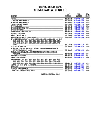
  • 1. ERP040-060DH (E216) SERVICE MANUAL CONTENTS SECTION PART NUMBER YRM NUMBER REV DATE FRAME............................................................................................................................ 524256685 0100 YRM 1222 05/06 DC MOTOR MAINTENANCE.......................................................................................... 524158039 0620 YRM 0294 03/08 AC MOTOR MAINTENANCE.......................................................................................... 524183080 0620 YRM 1053 03/10 DRIVE AXLE WET BRAKE............................................................................................ 524256686 1400 YRM 1223 03/09 STEERING AXLE............................................................................................................ 524158752 1600 YRM 0316 08/06 STEERING CONTROL UNIT.......................................................................................... 524158753 1600 YRM 0720 11/06 STEERING SYSTEM...................................................................................................... 524183081 1600 YRM 1054 11/06 BRAKE PEDAL AND LINKAGE..................................................................................... 524264587 1800 YRM 1253 09/06 HYDRAULIC SYSTEM.................................................................................................... 524179945 1900 YRM 0559 04/09 MAIN CONTROL VALVE................................................................................................ 524179946 2000 YRM 0562 02/09 MAIN CONTROL VALVE E-CONTROLS....................................................................... 524256687 2000 YRM 1224 04/08 CYLINDER REPAIR (MAST S/N A551, A555, A559, A661, A662, A663, A66, B507, B508, B509, B551, B555, B559, B562, B563, B564, B661, B662, B663, C515, C551, C555, C559, D507, D508, D509, D515, D562, D563, D564, E509, AND E564).......................................................................................................................... 524223768 2100 YRM 1139 02/14 ELECTRICAL SYSTEM.................................................................................................. 524183082 2200 YRM 1055 10/09 AC MOTOR CONTROLLER DESC/CHKS/ADJ/TRBSHT/REP&THEORY OF OPERATION/DISPLAY PANEL................................................................................. 524183083 2200 YRM 1056 03/09 TROUBLESHOOTING AND ADJUSTMENTS USING THE AC CONTROLS PROGRAM................................................................................................................. 524183085 2200 YRM 1058 04/11 INDUSTRIAL BATTERY................................................................................................. 524158040 2240 YRM 0001 09/14 MAST - DESCRIPTION................................................................................................... 524158890 4000 YRM 0521 03/06 MAST REPAIRS (S/N A551, A555, A559, A661, A662, A663, A664, B507, B508, B509, B551, B555, B559, B562, B563, B564, B661, B662, B663, C515, C551, C555, C559, D507, D508, D509, D515, D562, D563, D564, E509, AND E564)........ 524223776 4000 YRM 1148 02/14 METRIC AND INCH (SAE) FASTENERS....................................................................... 524150797 8000 YRM 0231 10/13 DIAGRAMS..................................................................................................................... 524256688 8000 YRM 1225 05/06 PERIODIC MAINTENANCE............................................................................................ 524256689 8000 YRM 1226 08/08 CAPACITIES AND SPECIFICATIONS........................................................................... 524256690 8000 YRM 1227 05/06 PART NO. 524256684 (09/14)
  • 2. SAFETY PRECAUTIONS MAINTENANCE AND REPAIR • When lifting parts or assemblies, make sure all slings, chains, or cables are correctly fastened, and that the load being lifted is balanced. Make sure the crane, cables, and chains have the capacity to support the weight of the load. • Do not lift heavy parts by hand, use a lifting mechanism. • Wear safety glasses. • DISCONNECT THE BATTERY CONNECTOR before doing any maintenance or repair on electric lift trucks. Disconnect the battery ground cable on internal combustion lift trucks. • Always use correct blocks to prevent the unit from rolling or falling. See HOW TO PUT THE LIFT TRUCK ON BLOCKS in the Operating Manual or the Periodic Maintenance section. • Keep the unit clean and the working area clean and orderly. • Use the correct tools for the job. • Keep the tools clean and in good condition. • Always use YALE APPROVED parts when making repairs. Replacement parts must meet or exceed the specifications of the original equipment manufacturer. • Make sure all nuts, bolts, snap rings, and other fastening devices are removed before using force to remove parts. • Always fasten a DO NOT OPERATE tag to the controls of the unit when making repairs, or if the unit needs repairs. • Be sure to follow the WARNING and CAUTION notes in the instructions. • Gasoline, Liquid Petroleum Gas (LPG), Compressed Natural Gas (CNG), and Diesel fuel are flammable. Be sure to follow the necessary safety precautions when handling these fuels and when working on these fuel systems. • Batteries generate flammable gas when they are being charged. Keep fire and sparks away from the area. Make sure the area is well ventilated. NOTE: The following symbols and words indicate safety information in this manual: WARNING Indicates a hazardous situation which, if not avoided, could result in death or serious injury. CAUTION Indicates a hazardous situation which, if not avoided, could result in minor or moderate injury and property damage. On the lift truck, the WARNING symbol and word are on orange background. The CAUTION symbol and word are on yellow background.
  • 3. Drive Unit Assembly Table of Contents TABLE OF CONTENTS General................................................................................................................................................................ 1 Description .......................................................................................................................................................... 1 Wet Disc Brake Repair ........................................................................................................................................ 5 Wet Disc Brakes.............................................................................................................................................. 5 Remove....................................................................................................................................................... 5 Inspect ........................................................................................................................................................ 9 Install .......................................................................................................................................................... 9 Gearbox Replacement......................................................................................................................................... 14 Remove........................................................................................................................................................... 14 Gearbox Removal ....................................................................................................................................... 14 Intermediate Flange Removal..................................................................................................................... 15 Disassemble.................................................................................................................................................... 17 Intermediate Flange.................................................................................................................................... 17 Assemble ........................................................................................................................................................ 25 Intermediate Flange.................................................................................................................................... 25 Install............................................................................................................................................................... 38 Intermediate Flange Installation.................................................................................................................. 38 Gearbox Installation.................................................................................................................................... 40 Drive Unit Removal.............................................................................................................................................. 42 Main Housing Repair........................................................................................................................................... 46 Main Housing, Right-Hand Side...................................................................................................................... 46 Remove....................................................................................................................................................... 46 Disassemble ............................................................................................................................................... 47 Clean and Inspect....................................................................................................................................... 48 Assemble .................................................................................................................................................... 49 Install .......................................................................................................................................................... 49 Main Housing, Left-Hand Side ........................................................................................................................ 50 Remove....................................................................................................................................................... 50 Disassemble ............................................................................................................................................... 51 Clean and Inspect....................................................................................................................................... 52 Assemble .................................................................................................................................................... 52 Install .......................................................................................................................................................... 52 Differential Assembly Replacement..................................................................................................................... 53 Remove........................................................................................................................................................... 53 Install............................................................................................................................................................... 53 Traction Motor Repair .......................................................................................................................................... 54 Remove........................................................................................................................................................... 54 Disassemble.................................................................................................................................................... 54 Assemble ........................................................................................................................................................ 57 Install............................................................................................................................................................... 57 Drive Unit Installation........................................................................................................................................... 58 Torque Specifications .......................................................................................................................................... 59 Troubleshooting ................................................................................................................................................... 60 This section is for the following models: ERP20-30ALF (ERP040-060DH) [E216] ©2009 Yale Materials Handling Corp. i
  • 4. 1400 YRM 1223 Description General This section has the description and repair procedures for the differential, drive axle, traction motor, and the wet disc brakes. Description The drive unit consists of following main components (see Figure 1): • The traction motor with hollow shaft. • Mechanical differential assembly (located on left-hand side of traction motor shaft). • The gearbox with intermediate flange, containing the wet disc brakes. • Main housings, containing the pistons for the wet disc brakes and the parking brake levers. • Speed sensor and reluctor wheel (located on traction motor shaft, see Figure 8). 1. WHEEL HUB 2. GEARBOX (LH) 3. INTERMEDIATE FLANGE (LH) 4. MAIN HOUSING (LH) 5. PARKING BRAKE LEVER 6. TRACTION MOTOR 7. MAIN HOUSING (RH) 8. INTERMEDIATE FLANGE (RH) 9. GEARBOX (RH) 10. SPEED SENSOR 11. DIFFERENTIAL ASSEMBLY Figure 1. Drive Unit 1
  • 5. Description 1400 YRM 1223 The drive unit assembly is fastened to the frame of the lift truck by the frame mounts of the main housings. See Figure 2. The mast is mounted on the J-hook mountings of the main housings of the drive unit. See Figure 3. The traction motor is mounted in between the two main housings. The traction motor generates the power to the differential assembly. See Figure 4. 1. FRAME MOUNTS Figure 2. Drive Unit Frame Mounts 2
  • 6. 1400 YRM 1223 Description 1. J-HOOK MOUNTINGS Figure 3. Mast Mounting Hooks 1. WHEEL HUB 2. PLANETARY GEAR 3. INPUT SHAFT (RH) 4. DRIVE GEAR 5. AXLE SHAFT 6. TRACTION MOTOR SHAFT 7. DIFFERENTIAL ASSEMBLY 8. DRIVE GEAR 9. INPUT SHAFT (LH) 10. SUN PINION 11. DRIVEN GEAR 12. BRAKE DISC PACK 13. DISC PUSHER 14. PISTON 15. PARK BRAKE LEVER Figure 4. Drive Unit 3
  • 7. Description 1400 YRM 1223 The differential then transfers the power through the axle shaft to the input shafts located in the intermediate flange assemblies. The input shaft drive gears transfer the power to the driven gears. The driven gears then transfer the power to the sun pinion. See Figure 5. 1. DRIVE GEAR 2. INTERMEDIATE FLANGE 3. INPUT SHAFT 4. AXLE SHAFT 5. DRIVEN GEAR 6. SUN PINION Figure 5. Drive Gear, Driven Gear, and Sun Pinion The sun pinion then transfers the power to the plane- tary gears and planetary carrier which then engages the wheel hubs. See Figure 6. The wet brake discs are mounted on the intermediate flanges. The piston, which is located in the main hous- ing (one in each main housing), is activated when the brake pedal is applied. The piston presses against the disc pusher which compresses the brake friction discs and steel discs which causes the braking. See Figure 7. 1. PLANETARY CARRIER 2. PLANETARY GEARS 3. RING GEAR 4. WHEEL HUB Figure 6. Planetary Gears 1. INTERMEDIATE FLANGE 2. DISC PUSHER 3. BRAKE DISC PACK Figure 7. Brake Disc Pack 4
  • 8. 1400 YRM 1223 Wet Disc Brake Repair The parking brake levers press against the back of the piston which forces the piston to press against the disc pusher to compress the brakes friction discs and steel discs to mechanically apply the parking brake. The speed sensor is mounted on the main housing on the right-hand side of the drive unit. The reluctor wheel is mounted on the traction motor shaft on the right-hand side of the traction motor. The speed sensor is a hall effect sensor which reads the variation in its magnetic field when a tooth of the reluctor wheel passes the sen- sor. See Figure 8. 1. SPEED SENSOR 2. RELUCTOR WHEEL Figure 8. Speed Sensor and Reluctor Wheel Wet Disc Brake Repair WET DISC BRAKES For replacement of the pistons and piston seals, refer to the section Main Housing Repair. Remove STEP 1. Remove the gearbox. Refer to the section Gearbox Replacement. STEP 2. Press down on the disc pusher device and remove the retaining rings from the studs. 5
  • 9. Wet Disc Brake Repair 1400 YRM 1223 STEP 3. Remove the disc pusher device from the studs. 1. DISC PUSHER DEVICE 2. STUDS STEP 4. Remove the springs from the studs. If necessary, remove the studs. 6
  • 10. 1400 YRM 1223 Wet Disc Brake Repair 1. STUDS 2. SPRINGS STEP 5. Note the position of the notches on the steel discs for correct positioning during assembly. Remove one steel disc. 1. STEEL DISC 2. NOTCH 7
  • 11. Wet Disc Brake Repair 1400 YRM 1223 STEP 6. Remove the one friction disc. 1. FRICTION DISC STEP 7. Remove four springs/spacers. 1. SPRINGS/SPACERS 8
  • 12. 1400 YRM 1223 Wet Disc Brake Repair STEP 8. Repeat STEP 5 through STEP 7 until the last steel disc is removed. STEP 9. Remove the aluminum reaction disc. Inspect 1. Inspect the brake friction discs and brake steel discs. The discs must be measured as a pack (6 steel discs and 5 friction discs) to determine if the discs need replaced. Replace discs as a pack when the thickness is less than 23 mm (0.91 in.). A new disc pack will have a thickness of 23.95 to 24.45 mm (0.94 to 0.96 in.). When replacing the disc pack, all springs must also be replaced. 2. Inspect the aluminum reaction disc. Replace the aluminum reaction disc when the thickness is equal or less than 4.5 mm (0.18 in.). A new aluminum re- action disc will have a thickness of 4.95 to 5.05 mm (0.195 to 0.199 in.). Install STEP 1. If removed, install the four pins. 9
  • 13. Wet Disc Brake Repair 1400 YRM 1223 STEP 2. If removed, apply Loctite® 242 to the studs and install the studs. Tighten the studs to 2 N•m (17.7 lbf in). STEP 3. Install the aluminum reaction disc. NOTE: The first and last disc installed must be a smooth steel disc. STEP 4. Align the notch of the steel disc as noted during disas- sembly. Install one steel disc. 1. NOTCH 10
  • 14. 1400 YRM 1223 Wet Disc Brake Repair STEP 5. Install one friction disc. STEP 6. Install four springs/spacers. STEP 7. Repeat STEP 4 through STEP 6 until six steel discs and five frictions discs have been installed. 11
  • 15. Wet Disc Brake Repair 1400 YRM 1223 STEP 8. Install the springs onto the studs. 1. STUDS 2. SPRINGS STEP 9. Install the disc pusher device onto the studs. 12
  • 16. 1400 YRM 1223 Wet Disc Brake Repair 1. DISC PUSHER DEVICE 2. STUDS STEP 10. Press down on the disc pusher device and install the retaining rings into the seats on the studs. STEP 11. Install the gearbox. Refer to the section Gearbox Re- placement. 13
  • 17. Gearbox Replacement 1400 YRM 1223 Gearbox Replacement REMOVE Gearbox Removal WARNING When putting the lift truck on blocks, make sure the surface is solid, even, and level. Any blocks used to support the lift truck must be solid, one-piece units. 1. Put blocks on each side (front and back) of the steering tires to prevent movement of the lift truck. 2. Raise the lift truck and put blocks under the frame so that the drive wheels do not touch the floor. Put blocks under the counterweight for stability. 3. Remove the mast assembly as described in the section Mast Repairs, 2, 3, and 4-Stage Masts 4000 YRM 1148. 4. Disconnect the battery connector. 5. Remove the wheel from the wheel hub of the gear- box being replaced. 6. Remove the gearbox oil fill plug. See Figure 9. 7. Remove the gearbox magnetic drain plug to drain the oil from the gearbox into a suitable container. See Figure 9. 8. Remove the brake oil fill/breather plug from main housing. See Figure 9. 9. Remove the brake oil drain plug to drain the oil from the main housing into a suitable container. See Figure 9. 10. Place a sling connected to an overhead lift around the gearbox and wheel hub assembly and apply light tension to the sling. 11. Remove the socket-head screws retaining the gear- box to the main housing. Note the positions of the short and long socket-head screws for when the gearbox is installed. See Figure 10. 12. Remove the gearbox and wheel hub assembly. 1. BRAKE OIL FILL/BREATHER PLUG 2. GEARBOX OIL FILL PLUG 3. GEARBOX OIL DRAIN PLUG (MAGNETIC) 4. BRAKE OIL DRAIN PLUG Figure 9. Oil Refill and Drain Plugs 14
  • 18. 1400 YRM 1223 Gearbox Replacement Figure 10. Gearbox Removal/Installation Legend for Figure 10 1. M8 SOCKET-HEAD SCREWS, 3 EACH 2. M12 X 1.75 X 70 MM LONG SOCKET-HEAD SCREWS, 11 EACH 3. M12 X 1.75 X 40 MM SHORT SOCKET-HEAD SCREWS, 2 EACH Intermediate Flange Removal STEP 1. Remove the brake discs and friction plates. Refer to the section Wet Disc Brake Repair. STEP 2. For the left-hand side gearbox only, remove the spacer from the input shaft. 15
  • 19. Gearbox Replacement 1400 YRM 1223 STEP 3. Remove the socket-head screws used to retain the in- termediate flange to the gearbox housing. Insert a prybar into the pry slots between the interme- diate flange and the gearbox housing and pry upwards to break the seal between the flange and housing. 1. SOCKET-HEAD SCREWS 2. PRY SLOTS 16
  • 20. 1400 YRM 1223 Gearbox Replacement STEP 4. Remove the intermediate flange assembly from the gearbox housing. DISASSEMBLE Due to the requirement of specialized tools and equipment (which most service departments do not possess) to properly service this gearbox, it is highly recommended to replace rather than rebuild this as- sembly. Intermediate Flange NOTE: If the inner ring for the needle bearing is being replaced, the needle bearing in the gearbox housing must be replaced. STEP 1. Using an appropriate puller, remove the needle bearing from the gearbox housing. 1. GEARBOX 2. NEEDLE BEARING 17
  • 21. Gearbox Replacement 1400 YRM 1223 STEP 2. Remove the snap ring retaining the input shaft into the intermediate flange. 1. SNAP RING 2. INPUT SHAFT 18
  • 22. 1400 YRM 1223 Gearbox Replacement STEP 3. Using plastic or hard rubber hammer, tap the input shaft, on the gear side, with drive gear and bearing out of the intermediate flange. 1. INTERMEDIATE FLANGE 2. INPUT SHAFT ASSEMBLY STEP 4. Remove the retaining ring from the input shaft. 19
  • 23. Gearbox Replacement 1400 YRM 1223 STEP 5. Place a cylinder on the press workbench as shown. Cylinder dimensions: • Inside diameter - 41 mm (1.61 in.) • Outside diameter - 62 mm (2.44 in.) • Height - minimum 130 mm (5.12 in.) STEP 6. Place the input shaft assembly with drive gear side up on the cylinder. Place a cylinder (solid shaft) on top of the input shaft and use a press to press the input shaft out of the nee- dle bearing inner ring, the drive gear, and the bearing. Cylinder dimensions: • Diameter - maximum 18.5 mm (0.73 in.) • Height - minimum 45 mm (1.77 in.) 1. CYLINDER 2. NEEDLE BEARING INNER RING 3. DRIVE GEAR 4. BEARING 5. CYLINDER 6. WORKBENCH 20
  • 24. 1400 YRM 1223 Gearbox Replacement STEP 7. Remove the square key from the input shaft. 1. NEEDLE BEARING INNER RING 2. DRIVE GEAR 3. BEARING 4. SQUARE KEY 5. INPUT SHAFT 21
  • 25. Gearbox Replacement 1400 YRM 1223 STEP 8. Remove the snap ring from the sun pinion. 1. DRIVEN GEAR 2. SNAP RING 3. SUN PINON 22
  • 26. 1400 YRM 1223 Gearbox Replacement STEP 9. Place the intermediate flange on a cylinder with the gear side up and the sun pinion inserted into the cylinder. Using a press, carefully press the sun pinion out of the intermediate flange. Cylinder Dimensions: • Inside diameter - 92 mm (3.62 in.) • Outside diameter - 130 mm (5.12 in.) 1. DRIVEN GEAR 2. INTERMEDIATE FLANGE 3. SUN PINION STEP 10. Remove the square key from the sun pinion. 1. SQUARE KEY 2. SUN PINION 23
  • 27. Gearbox Replacement 1400 YRM 1223 STEP 11. Remove the snap ring retaining the bearing in the inter- mediate flange. 1. SNAP RING 2. INTERMEDIATE FLANGE 3. BEARING STEP 12. Using a press, remove the bearing from the intermedi- ate flange. 1. INTERMEDIATE FLANGE 2. BEARING 24
  • 28. 1400 YRM 1223 Gearbox Replacement ASSEMBLE Intermediate Flange STEP 1. Place a cylinder on the press workbench. Cylinder Dimensions: • Inside diameter - 39.5 mm (1.56 in.) • Outside diameter - 95 mm (3.74 in.) • Height - 55 mm (2.17 in.) STEP 2. Place the intermediate flange on the cylinder as shown. 25
  • 29. Gearbox Replacement 1400 YRM 1223 STEP 3. Place the bearing in position in the flange. STEP 4. Position a flanged sleeve on the bearing. Flanged sleeve dimensions: • Outside diameter - 79 mm (3.11 in.) STEP 5. Using a press, press the bearing into the intermediate flange. 26
  • 30. 1400 YRM 1223 Gearbox Replacement STEP 6. Install the snap ring to retain the bearing. STEP 7. Position the sun pinion on the cylinder. Cylinder Dimensions: • Inside diameter - 39.5 mm (1.56 in.) • Outside diameter - 95 mm (3.74 in.) • Height - 55 mm (2.17 in.) STEP 8. Position a cylinder on the inner ring of the bearing as shown. Cylinder Dimensions: • Inside diameter - 42.5 mm (1.67 in.) • Outside diameter - 61 mm (2.4 in.) • Height - minimum 85 mm (3.35 in.) 27
  • 31. Gearbox Replacement 1400 YRM 1223 STEP 9. Using a press, press on the inner ring of the bearing until the sun pinion is fully seated in the intermediate flange and bearing. STEP 10. Install the square key in the slot of the sun pinion. WARNING Hot parts. Wear protective clothing and gloves to prevent burns. STEP 11. Heat the driven gear to approximately 100 to 120 C (212 to 248 F). Position the driven gear on the sun pinion and align the slot in the driven gear with the square key on the sun pinion. 28
  • 32. 1400 YRM 1223 Gearbox Replacement STEP 12. Place a cylinder over the sun pinion onto the driven gear as shown. Cylinder Dimensions: • Inside diameter - 42.5 mm (1.67 in.) • Outside diameter - 61 mm (2.4 in.) • Height - minimum 85 mm (3.35 in.) STEP 13. Using a press, press the driven gear onto the sun pinon until the driven gear is fully seated. 29
  • 33. Gearbox Replacement 1400 YRM 1223 STEP 14. Install the snap ring onto the sun pinion to retain the driven gear. 1. DRIVEN GEAR 2. SNAP RING 3. SUN PINON 30
  • 34. 1400 YRM 1223 Gearbox Replacement STEP 15. Place a cylinder on the press workbench as shown. Cylinder dimensions: • Inside diameter - 25.5 mm (1.004 in.) • Outside diameter - 34 mm (1.34 in.) • Height - minimum 50 mm (1.97 in.) STEP 16. Place the input shaft bearing on the cylinder. STEP 17. Install the square key into the slot on the input shaft. 31
  • 35. Gearbox Replacement 1400 YRM 1223 STEP 18. Insert the input shaft into the bearing. NOTE: Right-hand side input shaft shown. NOTE: Left-hand side input shaft shown. STEP 19. Using a press, press the input shaft into the bearing. 32
  • 36. 1400 YRM 1223 Gearbox Replacement STEP 20. Apply a coat of oil, use gear lube 80W or gear oil SAE 80W-90 or equivalent, to the end of the input shaft as shown. STEP 21. Place the drive gear on the cylinder as shown. Cylinder dimensions: • Inside diameter - 25.5 mm (1.004 in.) • Outside diameter - 34 mm (1.34 in.) • Height - 150 mm (5.9 in.) STEP 22. Insert the input shaft into the drive gear while aligning the slot in the drive gear with the square key on the input shaft. 33
  • 37. Gearbox Replacement 1400 YRM 1223 STEP 23. Using a press, press the input shaft into the drive gear until the input shaft is fully seated against the drive gear. STEP 24. Place the inner ring of the needle bearing in position on the input shaft. STEP 25. Place a cylinder in position on the inner ring for the nee- dle bearing. Using a press, press the inner ring onto the input shaft until the inner ring is fully seated against the drive gear. Cylinder dimensions: • Inside diameter - 20.3 mm (0.80 in.) • Outside diameter - 25 mm (0.98 in.) • Height for inside diameter end - minimum 20 mm (0.79 in.) 34
  • 38. 1400 YRM 1223 Gearbox Replacement STEP 26. Install the retaining ring. STEP 27. Verify the retaining ring is fully seated. STEP 28. Place the input shaft assembly in position in the inter- mediate flange. 35
  • 39. Gearbox Replacement 1400 YRM 1223 STEP 29. Place a cylinder over the input shaft assembly as shown. Cylinder dimensions: • Inside diameter - 42 mm (1.65 in.) • Outside diameter - 60 mm (2.36 in.) • Height for inside diameter end - 120 mm (4.72 in.) STEP 30. Using a hard plastic or rubber hammer, tap the input shaft assembly into the intermediate flange. STEP 31. Install the snap ring to retain the input shaft assembly into the intermediate flange. 36
  • 40. 1400 YRM 1223 Gearbox Replacement STEP 32. Apply a coat of oil, use gear lube 80W or gear oil SAE 80W-90 or equivalent, to the housing of the input shaft needle bearing. STEP 33. Insert the needle bearing into the housing. Using a hard plastic or rubber hammer, tap the needle bearing into the housing until it is fully seated. 37
  • 41. Gearbox Replacement 1400 YRM 1223 INSTALL Intermediate Flange Installation STEP 1. Apply sealant (Yale Part Number 580074175) to the mating surface of the gearbox housing. STEP 2. Place the intermediate flange assembly in position on the gearbox housing. Using a hard plastic or rubber hammer, tap the inter- mediate flange assembly down to the gearbox housing until it is fully seated against the gearbox housing mat- ing surface. 38
  • 42. 1400 YRM 1223 Gearbox Replacement STEP 3. If removed, install the alignment pins into the intermedi- ate flange and gearbox housing. STEP 4. Apply Loctite® 242 to the threads of the socket-head screws used to retain the intermediate flange to the gearbox housing. Install the socket-head screws and tighten to 40 N•m (29.5 lbf ft). 39
  • 43. Gearbox Replacement 1400 YRM 1223 STEP 5. For the left-hand side gearbox only, install the spacer on the input shaft. STEP 6. Install the brake discs and friction plates. Refer to the section Wet Disc Brake Repair. Gearbox Installation 1. Apply sealant (Yale Part Number 580074175) to the mating surface of the intermediate flange and drive unit main housing as shown in Figure 11. 1. SEALANT (YALE PART NUMBER 580074175) Figure 11. Intermediate Flange and Main Housing Sealing Surfaces 40
  • 44. 1400 YRM 1223 Gearbox Replacement 2. Place a sling connected to an overhead lift around the new gearbox and wheel hub assembly and place the assembly in position onto the main hous- ing. 3. On the RH side gearbox only, apply multipurpose grease to the splined socket. 4. Apply Loctite® 242 to the socket-head screws used to retain the gearbox to the main housing. 5. Install the socket-head screws in the positions noted in Remove, Step 11. 6. Tighten the three M8 socket-head screws (item 1, Figure 10) to 40 N•m (29.5 lbf ft). 7. Tighten the M12 socket-head screws (items 2 and 3, Figure 10) to 80 N•m (59 lbf ft). 8. Install the brake oil drain plug and tighten to 18 to 23 N•m (13.3 to 16.96 lbf ft). See Figure 9. 9. Clean and install the gearbox magnetic drain plug and tighten to 18 to 23 N•m (13.3 to 16.96 lbf ft). See Figure 9. 10. Remove the oil level/check plugs for the brake chamber and the gearbox. See Figure 12. NOTE: Wait 5 to 10 minutes after fill to allow oil to lu- bricate parts within the brake chambers and top off the brake oil. 11. Add oil, use John Deere JDM J20C, to the brake chamber until the oil level check port has over- flowed. NOTE: Wait 5 to 10 minutes after fill to allow oil to lu- bricate parts within the gearbox chambers and top off gearbox. 12. Add oil, use gear lube 80W or gear oil SAE 80W-90 or equivalent, to the gearbox chamber until the oil check port has overflowed. A. AXLE TOP VIEW B. AXLE BOTTOM VIEW 1. BRAKE OIL FILL PLUG (BREATHER) 2. BRAKE OIL DRAIN PLUG 3. BRAKE OIL LEVEL/CHECK PLUG 4. GEARBOX OIL FILL PLUG 5. GEARBOX OIL DRAIN PLUG 6. GEARBOX OIL LEVEL/CHECK PLUG Figure 12. Gearbox Oil and Brake Oil Replacement 41
  • 45. Drive Unit Removal 1400 YRM 1223 13. Install the brake oil fill plug/breather and tighten to 15 N•m (11 lbf ft). 14. Install the brake oil level/check plug and tighten to 18 to 23 N•m (13.3 to 16.96 lbf ft). 15. Install the gearbox oil fill plug and tighten to 7 N•m (62 lbf in). 16. Install the gearbox oil level/check plug and tighten to 18 to 23 N•m (13.3 to 16.96 lbf ft). 17. Install the wheel on the wheel hub of the gearbox replaced. Tighten wheel nuts to 155 to 175 N•m (114 to 166 lbf ft). 18. Connect the battery connector. 19. Install the mast assembly as described in the sec- tion Mast Repairs, 2, 3, and 4-Stage Masts 4000 YRM 1148. 20. Raise the lift truck and remove blocks from under frame and from under the counterweight. Lower the lift truck. 21. Remove the blocks on each side (front and back) of the steering tires. 22. Operate the lift truck and check for proper operation and leaks. Drive Unit Removal WARNING When putting the lift truck on blocks, make sure the surface is solid, even, and level. Any blocks used to support the lift truck must be solid, one-piece units. 1. Put blocks on each side (front and back) of the steering tires to prevent movement of the lift truck. 2. Raise the lift truck and put blocks under the frame so that the drive wheels do not touch the floor. Put blocks under the counterweight for stability. 3. Remove the mast assembly as described in the section Mast Repairs, 2, 3, and 4-Stage Masts 4000 YRM 1148. 4. Disconnect the battery connector. 5. Remove the wheels. 6. Remove the parking brake cables. Refer to the sec- tion Brake Pedal and Linkage 1800 YRM 1253. 7. Remove the gearbox oil fill plug. See Figure 13. 8. Remove the gearbox magnetic drain plug to drain the oil from the gearbox into a suitable container. See Figure 13. 9. Remove the brake oil fill/breather plug from main housing. See Figure 13. 10. Remove the brake oil drain plug to drain the oil from the main housing into a suitable container. See Figure 13. 1. BRAKE OIL FILL/BREATHER PLUG 2. GEARBOX OIL FILL PLUG 3. GEARBOX OIL DRAIN PLUG (MAGNETIC) 4. BRAKE OIL DRAIN PLUG Figure 13. Oil Refill and Drain Plugs 42
  • 46. 1400 YRM 1223 Drive Unit Removal 11. Repeat Step 7 through Step 10 on the other side of the drive unit. 12. Disconnect the brake lines from the drive unit. See Figure 14. 13. Disconnect the electrical connector from the speed sensor. See Figure 15. 14. Disconnect the electrical connector from the trac- tion motor. 15. Tag the electrical cables connecting to the traction motor. Remove the nuts retaining the cables to the terminal block and disconnect the electrical cables. See Figure 15. 16. Place blocks under the drive unit and connect slings and lifting device. 17. Remove the bolts, washers, and nuts retaining the drive unit to the frame. See Figure 16. 18. Remove blocks and lower the drive unit. Pull drive unit forward and away from frame. 19. Place blocks under the drive unit. 1. BRAKE LINE (RH) 2. BRAKE LINE (LH) Figure 14. Drive Unit Brake Lines 43
  • 47. Drive Unit Removal 1400 YRM 1223 1. ELECTRICAL CABLE 2. NUT 3. TRACTION MOTOR ELECTRICAL CONNECTOR 4. SPEED SENSOR ELECTRICAL CONNECTOR Figure 15. Speed Sensor and Traction Motor Electrical Connectors 44
  • 48. 1400 YRM 1223 Drive Unit Removal 1. NUT 2. WASHER 3. BOLT Figure 16. Drive Unit Mounting Bolts and Nuts 45
  • 49. Main Housing Repair 1400 YRM 1223 Main Housing Repair MAIN HOUSING, RIGHT-HAND SIDE Remove 1. Remove the gearbox. See Gearbox Replacement. 2. Slide the axle shaft out of the drive unit from the right-hand side of the drive unit. See Figure 17. 3. Place a sling connected to an overhead lift around the main housing (RH) and apply light tension to the sling. 4. Remove the socket-head screws retaining the main housing (RH) to the traction motor and remove the main housing (RH). See Figure 18. 1. MAIN HOUSING (LH) 2. TRACTION MOTOR 3. SOCKET-HEAD SCREW 4. MAIN HOUSING (RH) 5. AXLE SHAFT Figure 17. Axle Shaft Removal 46
  • 50. 1400 YRM 1223 Main Housing Repair 1. TRACTION MOTOR 2. RELUCTOR WHEEL 3. MAIN HOUSING (RH) 4. SOCKET-HEAD SCREW (14 EACH) Figure 18. Main Housing (RH) Removal/Installation Disassemble 1. Pulling the parking brake lever, push the piston out of the brake disc side of the main housing. See Figure 19. 2. Remove the gaskets and O-rings (items 4, 5, 6, and 7 in Figure 19) from the piston housing. 3. Remove the seal from the main housing (RH). See Figure 19. 4. Remove the socket-head screw retaining the speed sensor and remove the speed sensor. See Fig- ure 19. 5. Remove the socket-head screw retaining the park- ing brake lever in the main housing (RH) and re- move the parking brake lever. See Figure 20. 47
  • 51. Main Housing Repair 1400 YRM 1223 1. SOCKET-HEAD SCREW 2. SPEED SENSOR 3. MAIN HOUSING (RH) 4. O-RING 5. GASKET 6. O-RINGS 7. GASKET 8. PISTON 9. SEAL Figure 19. Main Housing (RH) Clean and Inspect WARNING Cleaning solvents can be flammable and toxic and can cause skin irritation. When using cleaning sol- vents, always follow the recommendations of the manufacturer. WARNING Compressed air can move particles so that they cause injury to the user or to other personnel. Make sure that the path of the compressed air is away from all personnel. Wear protective goggles or a face shield to prevent injury to the eyes. Clean the parts of the main housing with solvent and dry with compressed air. Inspect all machined surfaces of the main housing and the piston for wear and damage. Parts that are damaged must be replaced. 48
  • 52. 1400 YRM 1223 Main Housing Repair 1. PARKING BRAKE LEVER 2. MAIN HOUSING (RH) 3. SOCKET-HEAD SCREW Figure 20. Parking Brake Lever Removal/ Installation Assemble NOTE: Always use new O-rings, gaskets, and seals when assembling the main housing. 1. Insert the first small O-ring in the back groove of the piston housing. Verify the O-ring is seated properly. See Figure 19. NOTE: The lip on the internal side of the gasket faces the disc brakes side. 2. Bend and insert the first small gasket over the O-ring in the back groove. Verify that the gasket completely covers the O-ring. See Figure 19. 3. Insert the second small O-ring in the next groove of the piston housing. Verify the O-ring is seated properly. See Figure 19. NOTE: The lip on the internal side of the gasket faces the disc brakes side. 4. Bend and insert the second small gasket over the O-ring in the groove. Verify that the gasket com- pletely covers the O-ring. See Figure 19. 5. Insert the two large O-rings in the first groove. Ver- ify the O-rings are seated properly. See Figure 19. NOTE: The lip on the internal side of the gasket faces the traction motor side. 6. Bend and insert the large gasket over the O-rings in the groove. Verify that the gasket completely covers both O-rings. See Figure 19. 7. Lubricate the piston with John Deere JDM J20C. 8. Insert the piston into the housing from the brake disc side of the main housing until it is fully inserted. See Figure 19. 9. Place the parking brake lever in position in the main housing (RH) and install the socket-head screw to retain the parking brake lever in the hous- ing. Tighten the socket-head screw to 40 N•m (29.5 lbf ft). See Figure 20. 10. Place the seal in position in the main housing (RH). Using a seal driver, drive the seal into the housing until the seal is fully seated. See Figure 19. 11. Install the speed sensor into the main housing (RH). Install the socket-head screw to retain the speed sensor and tighten the socket-head screw to 5 N•m (44 lbf in). See Figure 19. Install 1. Place a sling connected to an overhead lift around the main housing and place the main housing in position onto the traction motor. 2. Install the socket-head screws to secure the main housing to the traction motor. Tighten the socket- head screws to 40 N•m (29.5 lbf ft). See Figure 18. 3. Slide the axle shaft into the drive unit from the right- hand side of the drive unit. See Figure 17. 4. Install the gearbox. See Gearbox Replacement. 49
  • 53. Main Housing Repair 1400 YRM 1223 MAIN HOUSING, LEFT-HAND SIDE Remove 1. Remove the gearbox. See Gearbox Replacement. 2. Place a sling connected to an overhead lift around the main housing (LH) and apply light tension to the sling. 3. Remove the socket-head screws retaining the main housing (LH) to the traction motor and remove the main housing (LH). See Figure 21. 4. Remove and discard the two O-rings from the main housing (LH). See Figure 22. 1. TRACTION MOTOR 2. DIFFERENTIAL 3. MAIN HOUSING (RH) 4. SOCKET-HEAD SCREW (14 EACH) Figure 21. Main Housing (LH) Removal/Installation 50
  • 54. 1400 YRM 1223 Main Housing Repair Figure 22. Main Housing (LH) O-rings Legend for Figure 22 1. O-RING 2. O-RING 3. MAIN HOUSING (LH) Disassemble 1. Pulling the parking brake lever, push the piston out of the brake disc side of the main housing (LH). See Figure 23. 2. Remove the gaskets and O-rings (items 2, 3, 4, and 5 in Figure 23) from the piston housing. 1. MAIN HOUSING (LH) 2. O-RING 3. GASKET 4. O-RINGS 5. GASKET 6. PISTON Figure 23. Main Housing (LH) 51
  • 55. Main Housing Repair 1400 YRM 1223 3. Remove the socket-head screw retaining the park- ing brake lever in the main housing (LH) and re- move the parking brake lever. See Figure 24. 1. MAIN HOUSING (LH) 2. PARKING BRAKE LEVER 3. SOCKET-HEAD SCREW Figure 24. Parking Brake Lever (LH) Removal/Installation Clean and Inspect WARNING Cleaning solvents can be flammable and toxic and can cause skin irritation. When using cleaning sol- vents, always follow the recommendations of the manufacturer. WARNING Compressed air can move particles so that they cause injury to the user or to other personnel. Make sure that the path of the compressed air is away from all personnel. Wear protective goggles or a face shield to prevent injury to the eyes. Clean the parts of the main housing with solvent and dry with compressed air. Inspect all machined surfaces of the main housing and the piston for wear and damage. Parts that are damaged must be replaced. Assemble NOTE: Always use new O-rings, gaskets, and seals when assembling the main housing. 1. Insert the first small O-ring in the back groove of the piston housing. Verify the O-ring is seated properly. See Figure 23. NOTE: The lip on the internal side of the gasket faces the disc brakes side. 2. Bend and insert the first small gasket over the O-ring in the back groove. Verify that the gasket completely covers the O-ring. See Figure 23. 3. Insert the second small O-ring in the next groove of the piston housing. Verify the O-ring is seated properly. See Figure 23. NOTE: The lip on the internal side of the gasket faces the disc brakes side. 4. Bend and insert the second small gasket over the O-ring in the groove. Verify that the gasket com- pletely covers the O-ring. See Figure 23. 5. Insert the two large O-rings in the first groove. Ver- ify the O-rings are seated properly. See Figure 23. NOTE: The lip on the internal side of the gasket faces the traction motor side. 6. Bend and insert the large gasket over the O-rings in the groove. Verify that the gasket completely covers both O-rings. See Figure 23. 7. Lubricate the piston with John Deere JDM J20C. 8. Insert the piston into the housing from the brake disc side of the main housing until it is fully inserted. See Figure 23. 9. Place the parking brake lever in position in the main housing (LH) and install the socket-head screw to retain the parking brake lever in the hous- ing. Tighten the socket-head screw to 40 N•m (29.5 lbf ft). See Figure 24. Install 1. Place new O-rings in proper grooves on the main housing (LH). See Figure 22. 2. Place a sling connected to an overhead lift around the main housing and place the main housing in position onto the traction motor. 52
  • 56. 1400 YRM 1223 Differential Assembly Replacement 3. Install the socket-head screws to secure the main housing to the traction motor. Tighten the socket- head screws to 40 N•m (29.5 lbf ft). See Figure 21. 4. Install the gearbox. See Gearbox Replacement. Differential Assembly Replacement REMOVE NOTE: Do not disassemble the differential assembly. The differential assembly cannot be repaired and must be replaced as an assembly. 1. Remove the gearbox from the left-hand side of the drive unit. See Gearbox Replacement. 2. Remove the main housing from the left-hand side of the traction motor. See Main Housing, Left-Hand Side, Remove. 3. Slide the differential assembly off the splines of the traction motor shaft and the axle shaft. See Fig- ure 25. INSTALL 1. Slide the differential assembly onto the splines of the traction motor shaft and the axle shaft. See Figure 25. 2. Install the main housing onto the left-hand side of the traction motor. See Main Housing, Left-Hand Side, Install. 3. Install the gearbox onto the left-hand side of the drive unit. See Gearbox Replacement. 1. TRACTION MOTOR 2. TRACTION MOTOR SHAFT 3. DIFFERENTIAL ASSEMBLY 4. AXLE SHAFT Figure 25. Differential Removal 53
  • 57. Traction Motor Repair 1400 YRM 1223 Traction Motor Repair REMOVE 1. Remove the gearbox from the right-hand side of the drive unit. See Gearbox Replacement. 2. Remove the main housing from the right-hand side of the traction motor. See Main Housing, Right- Hand Side, Remove. 3. Remove the gearbox from the left-hand side of the drive unit. See Gearbox Replacement. 4. Remove the main housing from the left-hand side of the traction motor. See Main Housing, Left-Hand Side, Remove. 5. Remove the differential assembly. See Differential Assembly Replacement. DISASSEMBLE 1. Remove the seal from inside the hollow end of the left-hand side traction motor shaft. See Figure 26. 1. TRACTION MOTOR SHAFT 2. SNAP RING 3. SEAL Figure 26. Seal and Snap Ring 2. Remove the nuts retaining the electrical cables to the terminal block and disconnect the electrical ca- bles. See Figure 27. 3. Remove the torx-head screws retaining the terminal block to the traction motor and remove the terminal block. See Figure 27. 1. TORX-HEAD SCREWS 2. TERMINAL BLOCK 3. NUT 4. ELECTRICAL CABLE 5. SEAL Figure 27. Terminal Block 4. Remove the snap ring from the left-hand side trac- tion motor shaft. See Figure 26. 5. Remove the socket-head screws retaining the left- hand side traction motor end plate and remove the end plate with seal. See Figure 28. 1. SOCKET-HEAD SCREW 2. END PLATE 3. TRACTION MOTOR Figure 28. Left-Hand Side End Plate 54
  • 58. 1400 YRM 1223 Traction Motor Repair 6. If necessary, remove the seal for the electrical ca- bles. See Figure 29. 1. SEAL 2. TRACTION MOTOR Figure 29. Electrical Cable Seal 7. Remove the seal from the end plate. See Figure 30. 1. SEAL 2. END PLATE Figure 30. Left-Hand Side End Plate Seal CAUTION Do not damage the sealing surface of the traction motor shaft when removing the bearing. 8. Using an appropriate bearing puller, remove the bearing from the left-hand side traction motor shaft. See Figure 31. 1. BEARING 2. TRACTION MOTOR SHAFT 3. TRACTION MOTOR 4. SEALING SURFACE Figure 31. Left-Hand Side Bearing 9. Loosen the setscrew in the reluctor wheel located on the right-hand side of the traction motor shaft. See Figure 32. 10. Using a puller, remove the reluctor wheel. See Fig- ure 32. 11. Remove the socket-head screws retaining the right- hand side traction motor end plate and remove the end plate with spring. See Figure 33. 12. Remove and discard spring. See Figure 34. 13. Using an appropriate bearing puller, remove the bearing from the right-hand side traction motor shaft. See Figure 35. 55
  • 59. Traction Motor Repair 1400 YRM 1223 1. FLAT SPOT ON TRACTION MOTOR SHAFT 2. SETSCREW 3. RELUCTOR WHEEL Figure 32. Reluctor Wheel 1. TRACTION MOTOR 2. END PLATE 3. SOCKET-HEAD SCREW Figure 33. Right-Hand Side End Plate 1. SPRING 2. END PLATE Figure 34. End Plate Spring 1. TRACTION MOTOR 2. TRACTION MOTOR SHAFT 3. BEARING Figure 35. Right-Hand Side Bearing 56
  • 60. 1400 YRM 1223 Traction Motor Repair ASSEMBLE 1. Install the new bearing onto the right-hand side traction motor shaft. See Figure 35. 2. Place a new spring in the right-hand side traction motor end plate. See Figure 34. 3. Apply Loctite 243 to the threads of socket-head screws used to retain the end plate. 4. Place the right-hand side traction motor end plate in position on the traction motor and install the socket-head screws to retain the end plate. Tighten the socket head screws to 45 to 58 N•m (33.2 to 42.8 lbf ft). See Figure 33. 5. Align the hole for the setscrew in the reluctor wheel with the flat spot on the traction motor shaft and press the reluctor wheel onto the traction motor shaft. See Figure 32. 6. Tighten the setscrew to 4.7 to 5.3 N•m (41.6 to 46.9 lbf in). See Figure 32. 7. Install the new bearing onto the left-hand side trac- tion motor shaft. See Figure 31. 8. Install a new seal into the left-hand side end plate. See Figure 30. 9. If removed, install the seal for the electrical cables. See Figure 29. 10. Apply Loctite 243 to the threads of socket-head screws used to retain the end plate. CAUTION Do not damage the seal when assembling the trac- tion motor end plate on the traction motor shaft. 11. Apply a thin coat of multipurpose grease to the seal- ing surface of the left-hand side traction motor shaft. See Figure 31. Place the left-hand side traction mo- tor end plate in position on the traction motor and in- stall the socket-head screws to retain the end plate. Tighten the socket head screws to 45 to 58 N•m (33.2 to 42.8 lbf ft). See Figure 28. 12. Install the snap ring onto the left-hand side traction motor shaft. See Figure 26. 13. Place the terminal block in position on the traction motor and install the torx-head screws to retain the terminal block. Tighten the torx-head screws to 0.73 to 1.02 N•m (6.50 to 9.03 lbf in). See Fig- ure 27. 14. Connect the electrical cables to the terminal block and install nuts to retain cables. See Figure 27. 15. Apply a thin coat of multipurpose grease to the inner lip of the seal and install the seal into the hollow end of the left-hand side traction motor shaft. See Figure 26. INSTALL 1. Install the differential assembly. See Differential As- sembly Replacement. 2. Install the main housing onto the left-hand side of the traction motor. See Main Housing, Left-Hand Side, Install. 3. Install the gearbox onto the left-hand side of the drive unit. See Gearbox Replacement. 4. Install the main housing onto the right-hand side of the traction motor. See Main Housing, Right-Hand Side, Install. 5. Install the gearbox onto the right-hand side of the drive unit. See Gearbox Replacement. 57
  • 61. Drive Unit Installation 1400 YRM 1223 Drive Unit Installation 1. Connect slings and lifting device to drive unit. NOTE: When installing the drive unit, ensure the drive unit is held with the upper surface of the drive unit against the frame. This will prevent any gap between the frame and the drive unit mount, and will ensure even weight distribution. See Figure 36. 2. Position the drive unit in the lift truck. A. THE TOP SURFACE OF THE DRIVE UNIT SHOULD BE IN CONTACT WITH THE HANGER WHEN THE MOUNTING BOLTS ARE TIGHTENED. Figure 36. Drive Unit Mounting NOTE: It is recommended to use a torque multiplier to achieve the torque specification in Step 3. 3. Install the four mounting bolts, washers, and nuts. Tighten the bolts and nuts to 820 to 902 N•m (605 to 665 lbf ft). See Figure 16. 4. Connect the electrical cables to the traction motor terminal block. Install the nuts to retain the cables to the terminal block and tighten to 21 to 25 N•m (15.5 to 18.4 lbf in). See Figure 15. 5. Connect the electrical connector to the traction mo- tor. See Figure 15. 6. Connect the electrical connector to the speed sen- sor. See Figure 15. 7. Connect the brake lines to the drive unit. See Fig- ure 14. 8. Install the brake oil drain plug and tighten to 18 to 23 N•m (13.3 to 16.96 lbf ft). See Figure 9. 9. Clean and install the gearbox magnetic drain plug and tighten to 18 to 23 N•m (13.3 to 16.96 lbf ft). See Figure 9. 10. Remove the oil level/check plugs for the brake chamber and the gearbox. See Figure 12. NOTE: Wait 5 to 10 minutes after fill to allow oil to lubri- cate parts within the brake chambers and top off brake oil. 11. Add oil, use John Deere JDM J20C, to the brake chamber until the oil level check port has over- flowed. NOTE: Wait 5 to 10 minutes after fill to allow oil to lu- bricate parts within the gearbox chambers and top off gearbox. 12. Add oil, use gear lube 80W or gear oil SAE 80W-90 or equivalent, to the gearbox chamber until the oil check port has overflowed. 13. Install the brake oil fill plug/breather and tighten to 15 N•m (11 lbf ft). 14. Install the brake oil level/check plug and tighten to 18 to 23 N•m (13.3 to 16.96 lbf ft). 15. Install the gearbox oil fill plug and tighten to 7 N•m (62 lbf in). 16. Install the gearbox oil level/check plug and tighten to 18 to 23 N•m (13.3 to 16.96 lbf ft). 17. Repeat Step 8 through Step 16 on the opposite side. 18. Install the parking brake cables. Refer to the sec- tion Brake Pedal and Linkage 1800 YRM 1253. 19. Install the wheels. Tighten wheel nuts to 155 to 175 N•m (114 to 166 lbf ft). 20. Connect the battery connector. 21. Remove the air from the brake system as described in the section Brake Pedal and Linkage 1800 YRM 1253. 58
  • 62. 1400 YRM 1223 Torque Specifications 22. Install the mast assembly as described in the sec- tion Mast Repairs, 2, 3, and 4-Stage Masts 4000 YRM 1148. 23. Raise the lift truck and remove blocks from under frame and from under the counterweight. Lower the lift truck. 24. Remove the blocks on each side (front and back) of the steering tires. 25. Operate the lift truck and check for proper operation and leaks. Torque Specifications Brake Oil Drain Plug 18 to 23 N•m (13.3 to 16.96 lbf ft) Brake Oil Fill Plug/Breather 15 N•m (11 lbf ft) Brake Oil Level/Check Plug 18 to 23 N•m (13.3 to 16.96 lbf ft) Disc Pusher Studs 2 N•m (17.7 lbf in) Drive Unit Mounting Bolts and Nuts 820 to 902 N•m (605 to 665 lbf ft) Gearbox to Main Housing Socket-head Screws M8 40 N•m (29.5 lbf ft) M12 80 N•m (59 lbf ft) Gearbox Magnetic Drain Plug 18 to 23 N•m (13.3 to 16.96 lbf ft) Gearbox Oil Fill Plug 7 N•m (62 lbf in) Gearbox Oil Level/Check Plug 18 to 23 N•m (13.3 to 16.96 lbf ft) Intermediate Flange to Gearbox Socket-head Screws 40 N•m (29.5 lbf ft) Main Housing to Traction Motor Socket-head Screws 40 N•m (29.5 lbf ft) Parking Brake Lever Socket-head Screw 40 N•m (29.5 lbf ft) Reluctor Wheel Setscrew 4.7 to 5.3 N•m (41.6 to 46.9 lbf in) Speed Sensor Socket-head Screw 5 N•m (44 lbf in) Terminal Block Electrical Cable Retaining Nuts 21 to 25 N•m (15.5 to 18.4 lbf in) Terminal Block Torx-head Screws 0.73 to 1.02 N•m (6.50 to 9.03 lbf in) Traction Motor End Plate Socket-head Screws 45 to 58 N•m (33.2 to 42.8 lbf ft) Wheel Nuts 155 to 175 N•m (114 to 166 lbf ft) 59
  • 63. Troubleshooting 1400 YRM 1223 Troubleshooting PROBLEM POSSIBLE CAUSE PROCEDURE OR ACTION Truck moves slow or in a jerky motion. Speed sensor detects no pulses. Replace speed sensor. Traction motor fails to operate. There is an inter-turn short circuit (be- tween different phases) or there is a bad crimp of the bundle of wires to the terminal block or a circuit interruption. Measure the resistance between two terminals (U-V, V-W or W-U). The re- sistance should be 5.2 milliohm with a measuring current of 1.00 A and accu- rately measure 5.2 mV. The lift truck will not move. An axle shaft is broken. Install new axle shaft. An input shaft is damaged or broken. Install new input shaft. The differential is damaged. Replace differential. Sun pinion is damaged. Install a new sun pinion. Reduction gears are damaged. Install new gearbox assembly. The drive axle has leaks. The drain or fill plug has damaged threads or the copper washer is dam- aged, is loose, or is missing. Repair threads. Replace copper washer. Tighten plug. Install miss- ing part. The O-rings or seals have damage. Install new O-rings and seals. Main housing is cracked. Install a new main housing. The drive axle makes noise. The bearings have damage. Install new parts. The brake assembly is damaged. Repair brake assembly. The oil level is low. Fill as required. Check for leaks. The drive unit mounting capscrews are loose. Tighten capscrews to specified torque. Reducer gears are damaged. Install new gearbox assembly. 60
  • 64. 1600 YRM 316 Description General This section has the description and repair procedures for the steering axle. See the following sections for additional information on the parts of the steering system: Steering Housing and Control Unit and Hydraulic System. Description The steering axle assembly includes an axle frame, steering cylinder, and two spindle and hub assemblies. See Figure 1. The steering axle is connected to the frame with center pivot mounts. The center pivot mounts on the axle frame are fastened to the lift truck frame with rubber mounts. The steering axle can make an articulated motion and gives the lift truck a smoother travel over rough surfaces. The end caps of the steering cylinder are also the mounts for the cylinder and are held to the shell by the mount capscrews. O-rings, seals, and wipers in the end caps are used to keep the oil inside the steering cylinder. The ends of the piston rod extend from both ends of the cylinder. A single piston and the seal are at the center of the rod. Oil pressure on one side of the piston moves the piston in the bore. When the piston moves in the bore, it pushes an equal amount of oil from the opposite end of the cylinder. This oil returns to the steering control unit. When the piston reaches the end of the stroke, a relief valve controls the oil pressure so the components are not damaged. Tie rods connect the spindle arms to the cylinder. 1. SPINDLE AND HUB ASSEMBLY 2. AXLE FRAME 3. BRACKET 4. RUBBER MOUNT 5. STEERING CYLINDER 6. NUT AND BOLT Figure 1. Steering Axle 1
  • 65. Steering Axle Assembly Repair 1600 YRM 316 Each spindle turns on two tapered roller bearings. The spindle and bearings are held in the axle frame by a kingpin. The preload on the bearings is controlled by a threaded nut on the bottom of the kingpin. The wheel or hub rotates on two tapered roller bearings and is held on the spindle by a castle nut. The preload on the bearings in the hub is adjusted by the castle nut. A grease seal in the inner hub and a hub cap protect the bearings from dirt and water. A wear sleeve in the inner hub protects the hub from wear by the seal. Steering Axle Assembly Repair REMOVE WARNING PUTTING THE LIFT TRUCK ON BLOCKS The lift truck must be put on blocks for some types of maintenance and repair. The removal of the fol- lowing assemblies will cause large changes in the center of gravity: drive axle, battery, or counter- weight. When the lift truck is put on blocks, put ad- ditional blocks in the following positions: 1. If the mast and drive axle are removed, put blocks under the counterweight so the lift truck cannot fall backward. 2. If the battery (electric lift trucks) or counter- weight is removed, put blocks under the mast so the lift truck cannot fall forward. Put the lift truck on blocks on a solid, even, and level surface. Make sure the blocks of stands have enough capacity to hold the lift truck. Use addi- tional blocks next to the tires as necessary to pre- vent movement of the lift truck. Make sure the lift- ing devices used during repairs can lift the weight of the parts and assemblies. NOTE: The steering axle assembly without the wheels weighs approximately 115 kg (250 lb). The steering axle can be removed without removing the counterweight. If necessary, remove counterweight as described in the Frame section. 1. Make sure wheels are set for straight travel. Put lift truck on blocks so steering axle can be removed. The top of the axle frame must have clearance un- der the counterweight so the steering axle can be removed. See Figure 1. 2. Disconnect hydraulic lines at steering cylinder. In- stall caps on cylinder and put plugs in hydraulic lines. The caps will prevent spindles from turning when axle is removed from under lift truck. 3. Slide a floor jack or forks of another lift truck un- der steering axle. Raise lifting device until it holds the weight of the axle assembly. Remove four cap- screws and nuts that fasten two brackets under rub- ber mounts. Remove brackets and slowly lower axle assembly onto wheels. Carefully roll axle as- sembly from under lift truck. INSTALL 1. Install rubber mounts on axle. Make sure the PART NO. on the mounts is right side up and facing away from axle frame. 2. Apply a lubricant that is approved for use with rub- ber to rubber mount. The lubricant is used where the rubber mount fits into the frame brackets. 3. Use a floor jack or another lift truck to put steer- ing axle into position in frame. Make sure rubber mounts fit inside frame brackets for mounts. 4. Install bottom brackets. Tighten four bracket cap- screws and nuts to 88 N•m (65 lbf ft). 5. Remove plugs and caps and connect hydraulic lines to steering cylinder. 6. Operate steering system to remove air from sys- tem. Turn steering wheel several times from one stop to the other stop. Check for hydraulic leaks. 2
  • 66. 1600 YRM 316 Wheels and Hubs Repair Wheels and Hubs Repair REMOVE AND DISASSEMBLE WARNING PUTTING THE LIFT TRUCK ON BLOCKS The lift truck must be put on blocks for some types of maintenance and repair. The removal of the fol- lowing assemblies will cause large changes in the center of gravity: drive axle, battery, or counter- weight. When the lift truck is put on blocks, put ad- ditional blocks in the following positions: 1. If the mast and drive axle are removed, put blocks under the counterweight so the lift truck cannot fall backward. 2. If the battery (electric lift trucks) or counter- weight is removed, put blocks under the mast so that the lift truck cannot fall forward. Put the lift truck on blocks on a solid, even, and level surface. Make sure the blocks of stands have enough capacity to hold the lift truck. Use addi- tional blocks next to the tires as necessary to pre- vent movement of the lift truck. Make sure the lift- ing devices used during repairs can lift the weight of the parts and assemblies. WARNING Completely deflate the tires before removing them from the lift truck. Air pressure in the tires can cause the tire and rim parts to explode, causing se- rious injury or death. Never loosen the nuts that hold the inner and outer wheel halves together when there is air pressure in the tire. 1. Put axle on blocks so tires are raised from floor. Remove grease cap. Remove cotter pin and castle nut. Remove outer bearing cone. Slide wheel from spindle. Remove inner bearing cone and seal from spindle. See Figure 2. 2. If the wheel bearings must be replaced, use a brass drift to remove bearing cups and wear sleeve. 3. Repeat procedure for other wheel. CLEAN WARNING Cleaning solvents can be flammable and toxic and can cause skin irritation. When using cleaning solvents, always follow the solvent manufacturer’s recommended safety procedures. Clean all parts with solvent. Make sure bearings are clean. ASSEMBLE AND INSTALL CAUTION Do not damage the seals during installation. 1. If wheel bearings must be replaced, use a press to install new bearing cups in wheel or hub. See Figure 2. Install new wear sleeve in wheel or hub. Install grease seal on spindle. Lubricate bearing cones with grease. Make sure bearings are filled with grease. Install bearing cone on spindle. 2. Carefully slide wheel or hub onto spindle. Install outer bearing cone. 3. Install castle nut. Tighten castle nut to 200 N•m (150 lbf ft) while wheel is rotated. Loosen nut to less than 27 N•m (20 lbf ft). Tighten nut to 34 N•m (25 lbf ft). If cotter pin cannot be installed with nut tightened to 34 N•m (25 lbf ft), tighten castle nut until cotter pin can be installed. Install cotter pin. 4. Repeat procedure for other wheel. 3
  • 67. Wheels and Hubs Repair 1600 YRM 316 NOTE: GP2.00-3.00RF/TF (GP040-060RG/TG/ZG) SHOWN, OTHERS SIMILAR. 1. AXLE FRAME 2. WASHER 3. BOLT 4. BELLEVILLE WASHER 5. RUBBER MOUNT 6. BRACKET 7. NUT 8. STEERING CYLINDER 9. PIN 10. SNAP RING 11. BUSHING 12. TIE ROD 13. GREASE FITTING 14. CASTLE NUT 15. SLEEVE 16. SEAL 17. BEARING CONE 18. BEARING CUP 19. SPINDLE 20. SPACER 21. O-RING 22. KINGPIN 23. GROOVE PIN 24. WEAR SLEEVE 25. HUB* 26. STUD* 27. WHEEL NUT* 28. COTTER PIN 29. GREASE CAP *PNEUMATIC TIRES ONLY Figure 2. Steering Axle 4
  • 68. 1600 YRM 316 Spindles, Bearings, and Tie Rods Repair Spindles, Bearings, and Tie Rods Repair REMOVE WARNING PUTTING THE LIFT TRUCK ON BLOCKS The lift truck must be put on blocks for some types of maintenance and repair. The removal of the fol- lowing assemblies will cause large changes in the center of gravity: drive axle, battery, or counter- weight. When the lift truck is put on blocks, put ad- ditional blocks in the following positions: 1. If the mast and drive axle are removed, put blocks under the counterweight so the lift truck cannot fall backward. 2. If the battery (electric lift trucks) or counter- weight is removed, put blocks under the mast so the lift truck cannot fall forward. Put the lift truck on blocks on a solid, even, and level surface. Verify the blocks of stands have enough capacity to hold the lift truck. Use additional blocks next to the tires as necessary to prevent movement of the lift truck. Verify the lifting devices used dur- ing repairs can lift the weight of the parts and as- semblies. NOTE: Dirt and corrosion can make the spacer difficult to remove from the steering axle frame. A machined space is made in the top of the spacer so that the spacer can be removed with a bearing puller. Remove wheel or hub from steering axle spindle. See Figure 3. Remove pin to disconnect tie rod from spindle. Remove cotter pin and castle nut from bottom of king- pin. Use a driver to remove kingpin. Remove sleeve and then spindle from axle. Use a driver to remove bearings and seals from spindle. INSTALL 1. Use new bearings and seals. See Figure 2 and Figure 3. Apply grease to bearings and kingpin as they are installed in axle. Install bearings in spin- dle. Install seals in correct position. Align spindle in axle and install kingpin. Make sure new O-ring is installed at top of kingpin. Install sleeve on bot- tom of kingpin. Install castle nut and tighten it to 90 N•m (66 lbf ft). Loosen castle nut to less than 34 N•m (25 lbf ft). Tighten nut to 34 N•m (25 lbf ft). If cotter pin cannot be installed with nut tightened to 34 N•m (25 lbf ft), tighten castle nut until cotter pin can be installed. Install cotter pin. 1. O-RING 2. KINGPIN 3. GROOVE PIN 4. SPACER 5. SEAL 6. BEARING CONE 7. BEARING CUP 8. SPINDLE 9. SEAL 10. WEAR SLEEVE 11. CASTLE NUT 12. COTTER PIN 13. GREASE CAP 14. SLEEVE Figure 3. Spindle Assembly 2. Connect tie rods. Verify belleville washers are in- stalled on both sides of bushings. 3. Install wheels or hubs. See the section Wheels and Hubs Repair for proper installation procedure. Tighten wheel nuts to 237 to 305 N•m (175 to 225 lbf ft). 5
  • 69. Steering Cylinder Repair 1600 YRM 316 Steering Cylinder Repair REMOVE AND DISASSEMBLE WARNING PUTTING THE LIFT TRUCK ON BLOCKS The lift truck must be put on blocks for some types of maintenance and repair. The removal of the fol- lowing assemblies will cause large changes in the center of gravity: drive axle, battery, or counter- weight. When the lift truck is put on blocks, put ad- ditional blocks in the following positions: 1. If the mast and drive axle are removed, put blocks under the counterweight so the lift truck cannot fall backward. 2. If the battery (electric lift trucks) or counter- weight is removed, put blocks under the mast so the lift truck cannot fall forward. Put the lift truck on blocks on a solid, even, and level surface. Make sure the blocks of stands have enough capacity to hold the lift truck. Use addi- tional blocks next to the tires as necessary to pre- vent movement of the lift truck. Make sure the lift- ing devices used during repairs can lift the weight of the parts and assemblies. NOTE: The end caps of the steering cylinder are held in the shell by the cylinder mount capscrews. To prevent oil leaks at the caps, hold caps on shell during removal. 1. Disconnect hydraulic lines at steering cylinder. See Figure 4. Install caps in fittings on cylinders and put caps on hydraulic lines. 2. Remove snap rings from pins in tie rods. Remove pins. 3. Remove capscrews or nuts and bolts that fasten cylinder to axle frame. Hold end caps on shell and remove steering cylinder. 1. ROD 2. WIPER 3. END CAP 4. O-RING 5. BACKUP RING 6. SHELL 7. PISTON SEAL 8. ROD SEAL 9. QUADRANT RING Figure 4. Steering Cylinder 6
  • 70. 1600 YRM 316 Torque Specifications 4. Hold end of steering cylinder over drain pan. Re- move cap for hydraulic fitting from each end cap. Push rod toward end of shell that is over drain pan. Oil will drain from cylinder. Repeat procedure for other end. 5. Carefully slide one end cap from shell. Carefully pull cylinder rod and piston from shell. Keep cylin- der rod aligned in center of shell during removal so parts are not damaged. Remove end cap from rod. Remove other end cap from shell. Remove all seals, wipers, and O-rings. CLEAN AND INSPECT WARNING Cleaning solvents can be flammable and toxic and can cause skin irritation. When using cleaning solvents, always follow the solvent manufacturer’s recommended safety procedures. 1. Clean all parts in solvent. 2. Inspect piston rod for grooves or damage. Remove small scratches with fine emery cloth. Inspect cylin- der bore for damage. Inspect mounts for cracks. ASSEMBLE AND INSTALL 1. Put seals and wipers in warm hydraulic oil. Install quadrant ring and piston seal as shown in Figure 4. CAUTION Do not damage the O-rings, seals, or wipers during installation. 2. Lubricate O-rings, seals, and wipers with O-ring lu- bricant and install them in end caps. Install one end cap on cylinder rod. 3. Carefully slide cylinder rod and piston into shell. Keep cylinder rod aligned in center of shell during installation so parts are not damaged. Carefully slide end cap into shell. Carefully install other end cap on rod and shell. Put caps on hydraulic fittings of end caps. 4. Hold end caps and install cylinder on axle frame using capscrews or nuts and capscrews. Tighten capscrews to 225 N•m (166 lbf ft). 5. Install tie rods between cylinder and spindles. Make sure belleville washers are on each side of the bushings in the tie rods. Install pins and snap rings. 6. Remove caps and connect hydraulic lines to steer- ing cylinder. Operate steering system to remove air from cylinder and hydraulic system. Turn steering wheel several times from one stop to the other. Torque Specifications Steer Axle Mount Bracket Hardware 88 N•m (65 lbf ft) Wheel/Hub Nut Initial Torque 200 N•m (150 lbf ft) Final Torque 34 N•m (25 lbf ft) Kingpin Nut Initial Torque 90 N•m (66 lbf ft) Final Torque 34 N•m (25 lbf ft) Wheel Nuts 237 to 305 N•m (175 to 225 lbf ft) Steer Cylinder Mount Hardware 225 N•m (166 lbf ft) 7
  • 71. Troubleshooting 1600 YRM 316 Troubleshooting PROBLEM POSSIBLE CAUSE PROCEDURE OR ACTION There is no action when the steering wheel is turned. There is no oil or not enough oil in the hydraulic tank. Fill tank to correct level. The lines are loose at the control unit or manifold block. Tighten fittings. The sleeve and spool in the control unit will not move. Repair steering control unit. Steering cylinder leaks. Repair steering cylinder. Spacer for center pin is not installed. Assemble steering control unit cor- rectly. The lift truck steers slowly. The steering wheel is hard to turn. The oil level is low. There is no oil in the tank. Fill tank to correct level. The lines to the control unit are dam- aged. Repair oil lines. The sleeve and spool in the control unit are worn. Repair steering control unit. The parts of the metering section are worn. Repair steering control unit. The check valve in the control unit does not open. Clean or repair steering control unit. The check valve or relief valve in the manifold block is damaged or is not ad- justed correctly. Clean or replace manifold block. Priority valve is not operating correctly. Clean or repair priority valve. Steering relief pressure is too low. Adjust relief pressure. Engine idle speed is too low. Adjust idle speed to specifications. The steering wheel turns the tires in the wrong direction. The lines at the control unit are not cor- rectly connected. Connect lines correctly. 8
  • 72. 1600 YRM 316 Troubleshooting PROBLEM POSSIBLE CAUSE PROCEDURE OR ACTION The tires continue to turn after the steering wheel stops. The neutral position springs are bro- ken. Repair steering control unit. The sleeve or spool has damage. Repair steering control unit. Steering wheel kicks back in both directions. Center shaft is not correctly aligned with metering section. Correctly assemble steering control unit. 9
  • 73. Thank you very much for your reading. Please Click Here Then Get More Information.