Top Rated Call Girls Mumbai Central : 9920725232 We offer Beautiful and sexy ...
2010 Nissan 370Z Service Repair Manual.pdf
1. A
B
D
E
F
G
H
I
J
K
L
M
N
P
O
C
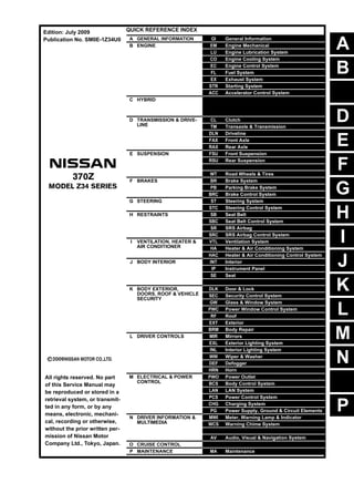
QUICK REFERENCE INDEX
A GENERAL INFORMATION GI General Information
B ENGINE EM Engine Mechanical
LU Engine Lubrication System
CO Engine Cooling System
EC Engine Control System
FL Fuel System
EX Exhaust System
STR Starting System
ACC Accelerator Control System
C HYBRID HBB Hybrid Battery System
HBR Hybrid Brake System
D TRANSMISSION & DRIVE-
LINE
CL Clutch
TM Transaxle & Transmission
DLN Driveline
FAX Front Axle
RAX Rear Axle
E SUSPENSION FSU Front Suspension
RSU Rear Suspension
SCS Suspension Control System
WT Road Wheels & Tires
F BRAKES BR Brake System
PB Parking Brake System
BRC Brake Control System
G STEERING ST Steering System
STC Steering Control System
H RESTRAINTS SB Seat Belt
SBC Seat Belt Control System
SR SRS Airbag
SRC SRS Airbag Control System
I VENTILATION, HEATER &
AIR CONDITIONER
VTL Ventilation System
HA Heater & Air Conditioning System
HAC Heater & Air Conditioning Control System
J BODY INTERIOR INT Interior
IP Instrument Panel
SE Seat
ADP Automatic Drive Positioner
K BODY EXTERIOR,
DOORS, ROOF & VEHICLE
SECURITY
DLK Door & Lock
SEC Security Control System
GW Glass & Window System
PWC Power Window Control System
RF Roof
EXT Exterior
BRM Body Repair
L DRIVER CONTROLS MIR Mirrors
EXL Exterior Lighting System
INL Interior Lighting System
WW Wiper & Washer
DEF Defogger
HRN Horn
M ELECTRICAL & POWER
CONTROL
PWO Power Outlet
BCS Body Control System
LAN LAN System
PCS Power Control System
CHG Charging System
PG Power Supply, Ground & Circuit Elements
N DRIVER INFORMATION &
MULTIMEDIA
MWI Meter, Warning Lamp & Indicator
WCS Warning Chime System
SN Sonar System
AV Audio, Visual & Navigation System
O CRUISE CONTROL CCS Cruise Control System
P MAINTENANCE MA Maintenance
All rights reserved. No part
of this Service Manual may
be reproduced or stored in a
retrieval system, or transmit-
ted in any form, or by any
means, electronic, mechani-
cal, recording or otherwise,
without the prior written per-
mission of Nissan Motor
Company Ltd., Tokyo, Japan.
Edition: July 2009
Publication No. SM0E-1Z34U0
2. FOREWORD
This manual contains maintenance and repair procedure for the 2010
NISSAN 370Z.
In order to assure your safety and the efficient functioning of the vehicle,
this manual should be read thoroughly. It is especially important that the
PRECAUTIONS in the GI section be completely understood before starting
any repair task.
All information in this manual is based on the latest product information
at the time of publication. The right is reserved to make changes in specifi-
cations and methods at any time without notice.
IMPORTANT SAFETY NOTICE
The proper performance of service is essential for both the safety of
the technician and the efficient functioning of the vehicle.
The service methods in this Service Manual are described in such a
manner that the service may be performed safely and accurately.
Service varies with the procedures used, the skills of the technician
and the tools and parts available. Accordingly, anyone using service
procedures, tools or parts which are not specifically recommended
by NISSAN must first be completely satisfied that neither personal
safety nor the vehicle’s safety will be jeopardized by the service
method selected.
3. QUICK REFERENCE CHART 370Z
QUICK REFERENCE CHART 370Z PFP:00000
ENGINE TUNE-UP DATA (VQ37VHR) ELS0003W
Engine model VQ37VHR
Firing order 1-2-3-4-5-6
Idle speed
A/T (In “P or N” position)
M/T (In Neutral position)
rpm
650 ± 50
Ignition timing
(BTDC at idle speed)
10° ± 5°
CO% at idle 0.7 - 9.9 % and engine runs smoothly
Tensions of drive belts Auto adjustment by auto tensioner
Radiater cap relief pressure kPa (kg/cm2
, psi)
Standard 122.3 - 151.7 (1.2 - 1.5, 18 - 22)
Limit 107 (1.1, 16)
Cooling system leakage testing pressure kPa (kg/cm2, psi)
157 (1.6, 23)
Compression pressure kPa (kg/cm2
, psi)/200 rpm
Standard 1,667 - 2,354 (17 - 24, 242 - 341)
Minimum 1,226 (12.5, 178)
Differential limit between cylinders 98 (1.0, 14)
Spark plug
(Iridium-tipped type)
Make DENSO
Standard type FXE24HR11
Gap (Nominal) mm (in) 1.1 (0.043)
2010
4. QUICK REFERENCE CHART 370Z
FRONT WHEEL ALIGNMENT ELS0003X
Measure value under unladen* conditions.
*: Fuel, engine coolant and lubricant are full. Spare tire, jack, hand tools and mats are in designated positions.
REAR WHEEL ALIGNMENT ELS0003Y
Measure value under unladen* conditions.
*: Fuel, engine coolant and lubricant are full. Spare tire, jack, hand tools and mats are in designated positions.
BRAKE PEDAL
Unit : mm (in.)
Camber
Degree minute (Decimal degree)
Minimum –1° 25′ (–1.41°)
Nominal –0° 40′ (–0.67°)
Maximum 0° 05′ (0.08°)
Left and right difference 0° 33′ (0.55°) or less
Caster
Degree minute (Decimal degree)
Minimum 4° 25′ (4.42°)
Nominal 5° 10′ (5.17°)
Maximum 5° 55′ (5.91°)
Left and right difference 0° 39′ (0.65°) or less
Kingpin inclination
Degree minute (Decimal degree)
Minimum 6° 55′ (6.92°)
Nominal 7° 40′ (7.67°)
Maximum 8° 25′ (8.41°)
Toe-in
Total toe-in
Distance
Minimum In 1 mm (0.04 in)
Nominal In 2 mm (0.08 in)
Maximum In 3 mm (0.11 in)
Toe angle (Left wheel or right wheel)
Degree minute (Decimal degree)
Minimum In 0° 03′ (0.05°)
Nominal In 0° 05′ (0.08°)
Maximum In 0° 07′ (0.11°)
Wheel size 18 inch 19 inch
Camber
Degree minute (Decimal degree)
Minimum –2° 10′ (–2.16°)
Nominal –1° 40′ (–1.67°)
Maximum –1° 10′ (–1.17°)
Toe-in
Total toe-in
Distance
Minimum In 2.0 mm (0.079 in) In 2.0 mm (0.079 in)
Nominal In 3.8 mm (0.150 in) In 3.7 mm (0.146 in)
Maximum In 5.6 mm (0.221 in) In 5.4 mm (0.213 in)
Toe angle (Left wheel or right wheel)
Degree minute (Decimal degree)
Minimum In 0° 05′ (0.09°)
Nominal In 0° 09′ (0.15°)
Maximum In 0° 13′ (0.21°)
Depressed brake pedal height (H1) 171.5 - 181.5 (6.75 - 7.15)
Brake pedal reserve height (H2)
[Depressing 490 N (50 kg, 110 lb) while turning the engine ON]
124.0 (4.88) or more
2010
5. QUICK REFERENCE CHART 370Z
FRONT DISK BRAKE
2 Piston Type
Unit : mm (in.)
4 Piston Type
Unit : mm (in.)
REAR DISK BRAKE
1 Piston Type
Unit : mm (in.)
2 Piston Type
Unit : mm (in.)
REFILL CAPACITIES ELS00040
Brake pad Wear limit thickness 2.0 (0.079)
Disc rotor Wear limit thickness 26.0 (1.024)
Brake pad Wear limit thickness 2.0 (0.079)
Disc rotor Wear limit thickness 30.0 (1.181)
Brake pad Wear limit thickness 2.0 (0.079)
Disc rotor Wear limit thickness 14.0 (0.551)
Brake pad Wear limit thickness 2.0 (0.079)
Disc rotor Wear limit thickness 18.0 (0.709)
UNIT Liter US measure Imp measure
Fuel tank 71.9 19 gal 15-7/8 gal
Engine Coolant (With reservoir
tank) at MAX level
A/T models 8.5 9 qt 7-1/2 qt
M/T models 8.6 9-1/8 qt 7-5/8 qt
Engine oil
Drain and refill
With oil filter change 4.9 5-1/8 qt 4-1/4 qt
Without oil filter change 4.6 4-7/8 qt 4 qt
Dry engine (Overhaul) 5.7 6 qt 5 qt
Transmission
A/T 9.2 9-3/4 qt 8-1/8 qt
M/T 2.83 6 pt 5 pt
Final drive Rear 1.4 3 pt 2-1/2 pt
Power steering system 1.0 1-1/8 qt 7/8 qt
Air conditioning system
Compressor oil 0.15 5.07 fl oz 5.3 fl oz
Refrigerant 0.5 kg 1.1 lb 1.1 lb
2010
6. GI-1
GENERAL INFORMATION
C
D
E
F
G
H
I
J
K
L
M
B
GI
SECTION GI
N
O
P
CONTENTS
GENERAL INFORMATION
REGULAR GRADE
HOW TO USE THIS MANUAL ..................
.... 3
HOW TO USE THIS MANUAL .......................
..... 3
Description ..........................................................
......3
Terms ..................................................................
......3
Units ....................................................................
......3
Contents ..............................................................
......3
Relation between Illustrations and Descriptions .
......4
Components ........................................................
......4
HOW TO FOLLOW TROUBLE DIAGNOSES..... 6
Description ..........................................................
......6
How to Follow Test Groups in Trouble Diagnosis......6
Key to Symbols Signifying Measurements or Pro-
cedures ...............................................................
......7
HOW TO READ WIRING DIAGRAMS ...........
..... 9
Connector Symbols .............................................
......9
Sample/Wiring Diagram -Example- .....................
....10
Connector Information .........................................
....12
ABBREVIATIONS ..........................................
....14
Abbreviation List ..................................................
....14
TIGHTENING TORQUE OF STANDARD
BOLTS ............................................................
....15
Description ..........................................................
....15
Tightening Torque Table (New Standard Includ-
ed) .......................................................................
....15
RECOMMENDED CHEMICAL PRODUCTS
AND SEALANTS ............................................
....18
Recommended Chemical Products and Sealants
....18
VEHICLE INFORMATION .........................
...19
IDENTIFICATION INFORMATION .................
....19
Model Variation ...................................................
....19
Information About Identification or Model Code ..
....20
Dimensions .........................................................
....22
Wheels & Tires ....................................................
....22
PRECAUTION ...........................................
...23
PRECAUTIONS .................................................23
Description ...........................................................
....23
FOR USA AND CANADA ......................................
....23
FOR USA AND CANADA : Precaution for Supple-
mental Restraint System (SRS) "AIR BAG" and
"SEAT BELT PRE-TENSIONER" ........................
....23
FOR USA AND CANADA : Precautions For Xenon
Headlamp Service ...............................................
....23
FOR USA AND CANADA : Precaution Necessary
for Steering Wheel Rotation after Battery Discon-
nect ......................................................................
....24
FOR USA AND CANADA : Precaution for Battery
Service .................................................................
....24
FOR USA AND CANADA : Precaution for Proce-
dure without Cowl Top Cover ..............................
....24
FOR USA AND CANADA : Service notice or Pre-
cautions for Rear Propeller Shaft ........................
....24
FOR MEXICO .........................................................
....24
FOR MEXICO : Precaution for Supplemental Re-
straint System (SRS) "AIR BAG" and "SEAT BELT
PRE-TENSIONER" ..............................................
....25
FOR MEXICO : Precautions For Xenon Headlamp
Service .................................................................
....25
FOR MEXICO : Precaution Necessary for Steer-
ing Wheel Rotation after Battery Disconnect .......
....25
FOR MEXICO : Precaution for Battery Service ...
....26
FOR MEXICO : Precaution for Procedure without
Cowl Top Cover ...................................................
....26
FOR MEXICO : Service notice or Precautions for
Rear Propeller Shaft ............................................
....26
General Precautions ............................................
....26
Three Way Catalyst .............................................
....28
Multiport Fuel Injection System or Engine Control
System .................................................................
....28
Hoses ..................................................................
....28
Revision: 2009 July 2010 370Z
7. GI-2
Engine Oils ..........................................................
... 29
Air Conditioning ...................................................
... 30
Service notice or Precautions for Rear Propeller
Shaft ....................................................................
... 30
Fuel ......................................................................
... 30
LIFTING POINT ..............................................
... 31
Commercial Service Tools ...................................
... 31
Garage Jack and Safety Stand and 2-Pole Lift ...
... 31
Board-On Lift .......................................................
... 32
TOW TRUCK TOWING ...................................
... 33
Tow Truck Towing ...............................................
... 33
Vehicle Recovery (Freeing a Stuck Vehicle) .......
... 33
BASIC INSPECTION ................................
... 35
SERVICE INFORMATION FOR ELECTRICAL
INCIDENT .......................................................
... 35
Work Flow ............................................................
... 35
Control Units and Electrical Parts ........................
... 35
How to Check Terminal .......................................
... 36
Intermittent Incident .............................................
... 39
Circuit Inspection .................................................
... 42
CONSULT-III/GST CHECKING SYSTEM ......
... 47
Description ...........................................................
... 47
CONSULT-III Function and System Application*1... 47
CONSULT-III/GST Data Link Connector (DLC)
Circuit ..................................................................
... 47
Wiring Diagram - CONSULT-III/GST CHECKING
SYSTEM - ............................................................
... 49
INSPECTION AND ADJUSTMENT ................
... 53
ADDITIONAL SERVICE WHEN REMOVING BAT-
TERY NEGATIVE TERMINAL ...............................
... 53
ADDITIONAL SERVICE WHEN REMOVING
BATTERY NEGATIVE TERMINAL : Required
Procedure After Battery Disconnection ................
... 53
Nismo 370Z
SPEC CHANGE INFORMATION ............... 54
IDENTIFICATION INFORMATION .................
... 54
Model Variation ....................................................
... 54
DIMENSIONS AND WEIGHTS .......................
... 55
Dimensions and Weights .....................................
... 55
PRECAUTION ............................................ 56
LIFTING POINT ..............................................
... 56
Lifting Point ..........................................................
... 56
TOW TRUCK TOWING ..................................
... 57
Tow Truck Towing ................................................
... 57
Vehicle Recovery (Freeing a Stuck Vehicle) ........
... 57
BACK DOOR ..................................................
... 59
Opening and Closing Back Door ..........................
... 59
Revision: 2009 July 2010 370Z
8. HOW TO USE THIS MANUAL
GI-3
< HOW TO USE THIS MANUAL > [REGULAR GRADE]
C
D
E
F
G
H
I
J
K
L
M
B
GI
N
O
P
HOW TO USE THIS MANUAL
HOW TO USE THIS MANUAL
Description INFOID:0000000005238416
This volume explains “Removal, Disassembly, Installation, Inspection and Adjustment” and “Trouble Diag-
noses”.
Terms INFOID:0000000005238417
• The captions WARNING and CAUTION warn you of steps that must be followed to prevent personal injury
and/or damage to some part of the vehicle.
WARNING indicates the possibility of personal injury if instructions are not followed.
CAUTION indicates the possibility of component damage if instructions are not followed.
BOLD TYPED STATEMENTS except WARNING and CAUTION give you helpful information.
Standard value: Tolerance at inspection and adjustment.
Limit value: The maximum or minimum limit value that should not be exceeded at inspection and adjust-
ment.
Units INFOID:0000000005238418
• The UNITS given in this manual are primarily expressed as the SI UNIT (International System of Unit), and
alternatively expressed in the metric system and in the yard/pound system.
Also with regard to tightening torque of bolts and nuts, there are descriptions both about range and about the
standard tightening torque.
“Example”
Range
Standard
Contents INFOID:0000000005238419
• A QUICK REFERENCE INDEX, a black tab (e.g. ) is provided on the first page. You can quickly find the
first page of each section by matching it to the section's black tab.
• THE CONTENTS are listed on the first page of each section.
• THE TITLE is indicated on the upper portion of each page and shows the part or system.
• THE PAGE NUMBER of each section consists of two or three letters which designate the particular section
and a number (e.g. “BR-5”).
• THE SMALL ILLUSTRATIONS show the important steps such as inspection, use of special tools, knacks of
work and hidden or tricky steps which are not shown in the previous large illustrations.
Assembly, inspection and adjustment procedures for the complicated units such as the automatic transaxle
or transmission, etc. are presented in a step-by-step format where necessary.
Outer Socket Lock Nut : 59 - 78 N·m (6.0 - 8.0 kg-m, 43 - 58 ft-lb)
Drive Shaft Installation Bolt : 44.3 N·m (4.5 kg-m, 33 ft-lb)
Revision: 2009 July 2010 370Z
9. GI-4
< HOW TO USE THIS MANUAL > [REGULAR GRADE]
HOW TO USE THIS MANUAL
Relation between Illustrations and Descriptions INFOID:0000000005238420
The following sample explains the relationship between the part description in an illustration, the part name in
the text and the service procedures.
Components INFOID:0000000005238421
• THE LARGE ILLUSTRATIONS are exploded views (see the following) and contain tightening torques, lubri-
cation points, section number of the PARTS CATALOG (e.g. SEC. 440) and other information necessary to
perform repairs.
The illustrations should be used in reference to service matters only. When ordering parts, refer to the appro-
priate PARTS CATALOG.
Components shown in an illustration may be identified by a circled number. When this style of illustration is
used, the text description of the components will follow the illustration.
SAIA0519E
Revision: 2009 July 2010 370Z
10. HOW TO USE THIS MANUAL
GI-5
< HOW TO USE THIS MANUAL > [REGULAR GRADE]
C
D
E
F
G
H
I
J
K
L
M
B
GI
N
O
P
SYMBOLS
1. Union bolt 2. Copper washer 3. Brake hose
4. Cap 5. Bleed valve 6. Sliding pin bolt
7. Piston seal 8. Piston 9. Piston boot
10. Cylinder body 11. Sliding pin 12. Torque member mounting bolt
13. Washer 14. Sliding pin boot 15. Bushing
16. Torque member 17. Inner shim cover 18. Inner shim
19. Inner pad 20. Pad retainer 21. Pad wear sensor
22. Outer pad 23. Outer shim 24. Outer shim cover
1: PBC (Poly Butyl Cuprysil) grease
or silicone-based grease
2: Rubber grease : Brake fluid
Refer to GI section for additional symbol definitions.
SFIA2959E
SAIA0749E
Revision: 2009 July 2010 370Z
11. GI-6
< HOW TO USE THIS MANUAL > [REGULAR GRADE]
HOW TO FOLLOW TROUBLE DIAGNOSES
HOW TO FOLLOW TROUBLE DIAGNOSES
Description INFOID:0000000005238422
NOTICE:
Trouble diagnoses indicate work procedures required to diagnose problems effectively. Observe the following
instructions before diagnosing.
• Before performing trouble diagnoses, read the “Work Flow” in each section.
• After repairs, re-check that the problem has been completely eliminated.
• Refer to Component Parts and Harness Connector Location for the Systems described in each section for
identification/location of components and harness connectors.
• When checking circuit continuity, ignition switch should be OFF.
• Refer to the Circuit Diagram for quick pinpoint check.
If you need to check circuit continuity between harness connectors in more detail, such as when a sub-har-
ness is used, refer to Wiring Diagram in each individual section and Harness Layout in PG section for identi-
fication of harness connectors.
• Before checking voltage at connectors, check battery voltage.
• After accomplishing the Diagnosis Procedures and Electrical Components Inspection, check that all harness
connectors are reconnected as they were.
How to Follow Test Groups in Trouble Diagnosis INFOID:0000000005238423
1. Test group number and test group title
• Test group number and test group title are shown in the upper portion of each test group.
2. Work and diagnosis procedure
• Start to diagnose a problem using procedures indicated in enclosed test groups.
3. Questions and results
• Questions and required results are indicated in test group.
4. Action
• Next action for each test group is indicated based on result of each question.
JPAIA0021GB
Revision: 2009 July 2010 370Z
12. HOW TO FOLLOW TROUBLE DIAGNOSES
GI-7
< HOW TO USE THIS MANUAL > [REGULAR GRADE]
C
D
E
F
G
H
I
J
K
L
M
B
GI
N
O
P
Key to Symbols Signifying Measurements or Procedures INFOID:0000000005238424
JPAIA0397GB
Revision: 2009 July 2010 370Z
13. GI-8
< HOW TO USE THIS MANUAL > [REGULAR GRADE]
HOW TO FOLLOW TROUBLE DIAGNOSES
JPAIA0398GB
Revision: 2009 July 2010 370Z
14. HOW TO READ WIRING DIAGRAMS
GI-9
< HOW TO USE THIS MANUAL > [REGULAR GRADE]
C
D
E
F
G
H
I
J
K
L
M
B
GI
N
O
P
HOW TO READ WIRING DIAGRAMS
Connector Symbols INFOID:0000000005570614
Most of connector symbols in wiring diagrams are shown from the terminal side.
• Connector symbols shown from the terminal side are enclosed by
a single line and followed by the direction mark.
• Connector symbols shown from the harness side are enclosed by
a double line and followed by the direction mark.
• Certain systems and components, especially those related to
OBD, may use a new style slide-locking type harness connector.
For description and how to disconnect, refer to PG section,
“Description”, “HARNESS CONNECTOR”.
• Male and female terminals
Connector guides for male terminals are shown in black and
female terminals in white in wiring diagrams.
SAIA0257E
SGI363
Revision: 2009 July 2010 370Z
15. GI-10
< HOW TO USE THIS MANUAL > [REGULAR GRADE]
HOW TO READ WIRING DIAGRAMS
Sample/Wiring Diagram -Example- INFOID:0000000005570615
Each section includes wiring diagrams.
Description
JCAWA0150GB
Number Item Description
1 Power supply • This means the power supply of fusible link or fuse.
2 Fuse • “/” means the fuse.
3
Current rating of fus-
ible link/fuse
• This means the current rating of the fusible link or fuse.
4
Number of fusible link/
fuse
• This means the number of fusible link or fuse location.
5 Fusible link • “X” means the fusible link.
6 Connector number
• Alphabetic characters show to which harness the connector is placed.
• Numeric characters show the identification number of connectors.
7 Switch
• This shows that continuity exists between terminals 1 and 2 when the switch is in the A
position. Continuity exists between terminals 1 and 3 when the switch is in the B position.
8 Circuit (Wiring) • This means the wiring.
Revision: 2009 July 2010 370Z
16. HOW TO READ WIRING DIAGRAMS
GI-11
< HOW TO USE THIS MANUAL > [REGULAR GRADE]
C
D
E
F
G
H
I
J
K
L
M
B
GI
N
O
P
SWITCH POSITIONS
Switches are shown in wiring diagrams as if the vehicle is in the “normal” condition.
A vehicle is in the “normal” condition when:
• ignition switch is “OFF”,
• doors, hood and trunk lid/back door are closed,
• pedals are not depressed, and
• parking brake is released.
MULTIPLE SWITCH
The continuity of multiple switch is described in two ways as shown below.
• The switch chart is used in schematic diagrams.
9 Shielded line • The line enclosed by broken line circle shows shield wire.
10 Connectors • This means that a transmission line bypasses two connectors or more.
11 Option abbreviation • This means the vehicle specifications which layouts the circuit between “ ”.
12 Relay • This shows an internal representation of the relay.
13 Optional splice • The open circle shows that the splice is optional depending on vehicle application.
14 Splice • The shaded circle “ ” means the splice.
15 System branch • This shows that the circuit is branched to other systems.
16 Page crossing • This circuit continues to an adjacent page.
17 Component name • This shows the name of a component.
18 Terminal number • This means the terminal number of a connector.
19 Ground (GND) • This shows the ground connection.
20
Explation of option
description
• This shows a explanation of the option abbreviation used on the same page.
Number Item Description
SGI860
Revision: 2009 July 2010 370Z
17. GI-12
< HOW TO USE THIS MANUAL > [REGULAR GRADE]
HOW TO READ WIRING DIAGRAMS
• The switch diagram is used in wiring diagrams.
Connector Information INFOID:0000000005570616
Description
JSAIA0017GB
Number Item Description
1 Connector number
• Alphabetic characters show to which harness the connector is placed.
• Numeric characters show the identification number of connectors.
2 Connector type • This means the connector number. Refer to PG-88, "How To Read Harness Layout".
3 Terminal number • This means the terminal number of a connector.
JCAWA0152GB
Revision: 2009 July 2010 370Z
18. HOW TO READ WIRING DIAGRAMS
GI-13
< HOW TO USE THIS MANUAL > [REGULAR GRADE]
C
D
E
F
G
H
I
J
K
L
M
B
GI
N
O
P
4 Wire color
• This shows a code for the color of the wire.
B = Black
W = White
R = Red
G = Green
L = Blue
Y = Yellow
LG = Light Green
BG = Beige
BR = Brown
OR or O = Orange
P = Pink
PU or V (Violet) = Purple
GY or GR = Gray
SB = Sky Blue
CH = Dark Brown
DG = Dark Green
• When the wire color is striped, the base color is given first, followed by the stripe color as
shown below:
Example: L/W = Blue with White Stripe
5 Connector
• This means the connector information.
• This unit-side is described by the connector symbols.
Number Item Description
Revision: 2009 July 2010 370Z
19. GI-14
< HOW TO USE THIS MANUAL > [REGULAR GRADE]
ABBREVIATIONS
ABBREVIATIONS
Abbreviation List INFOID:0000000005238428
The following ABBREVIATIONS are used:
ABBREVIATION DESCRIPTION
A/C Air Conditioner
A/T Automatic Transaxle/Transmission
ATF Automatic Transmission Fluid
D1 Drive range first gear
D2 Drive range second gear
D3 Drive range third gear
D4 Drive range fourth gear
FR, RR Front, Rear
LH, RH Left-Hand, Right-Hand
M/T Manual Transaxle/Transmission
OD Overdrive
P/S Power Steering
SAE Society of Automotive Engineers, Inc.
SDS Service Data and Specifications
SST Special Service Tools
2WD 2-Wheel Drive
22 2nd range second gear
21 2nd range first gear
12 1st range second gear
11 1st range first gear
Revision: 2009 July 2010 370Z
20. TIGHTENING TORQUE OF STANDARD BOLTS
GI-15
< HOW TO USE THIS MANUAL > [REGULAR GRADE]
C
D
E
F
G
H
I
J
K
L
M
B
GI
N
O
P
TIGHTENING TORQUE OF STANDARD BOLTS
Description INFOID:0000000005238429
This vehicle has both new standard based on ISO* and previous standard bolts/nuts. There are some differ-
ences between these two types of bolts/nuts: shape of the head, grade of strength, hexagonal width across
flats and the standard tightening torque.
• For guidance in discriminating, refer to GI-15, "Tightening Torque Table (New Standard Included)".
• The new standard machine screws and tapping screws have a head of ISO standard torx recess.
• If the tightening torque is not described in the description or figure, refer to GI-15, "Tightening Torque Table
(New Standard Included)".
*ISO: International Organization for Standardization
Tightening Torque Table (New Standard Included) INFOID:0000000005238430
CAUTION:
• The special parts are excluded.
• The bolts/nuts in these tables have a strength (discrimination) number/symbol assigned to the head
or the like. As to the relation between the strength grade in these tables and the strength (discrimi-
nation) number/symbol, refer to “DISCRIMINATION OF BOLTS AND NUTS”.
PREVIOUS STANDARD
CAUTION:
Grade
(Strength
grade)
Bolt
size
Bolt di-
ameter
mm
Hexagonal
width
across flats
mm
Pitch
mm
Tightening torque (Without lubricant)
Hexagon head bolt Hexagon flange bolt
N·m kg-m ft-lb in-lb N·m kg-m ft-lb in-lb
4T
M6 6.0 10 1.0 5.5 0.56 4 49 7 0.71 5 62
M8 8.0 12
1.25 13.5 1.4 10 — 17 1.7 13 —
1.0 13.5 1.4 10 — 17 1.7 13 —
M10 10.0 14
1.5 28 2.9 21 — 35 3.6 26 —
1.25 28 2.9 21 — 35 3.6 26 —
M12 12.0 17
1.75 45 4.6 33 — 55 5.6 41 —
1.25 45 4.6 33 — 65 6.6 48 —
M14 14.0 19 1.5 80 8.2 59 — 100 10 74 —
7T
M6 6.0 10 1.0 9 0.92 7 80 11 1.1 8 97
M8 8.0 12
1.25 22 2.2 16 — 28 2.9 21 —
1.0 22 2.2 16 — 28 2.9 21 —
M10 10.0 14
1.5 45 4.6 33 — 55 5.6 41 —
1.25 45 4.6 33 — 55 5.6 41 —
M12 12.0 17
1.75 80 8.2 59 — 100 10 74 —
1.25 80 8.2 59 — 100 10 74 —
M14 14.0 19 1.5 130 13 96 — 170 17 125 —
9T
M6 6.0 10 1.0 11 1.1 8 — 13.5 1.4 10 —
M8 8.0 12
1.25 28 2.9 21 — 35 3.6 26 —
1.0 28 2.9 21 — 35 3.6 26 —
M10 10.0 14
1.5 55 5.6 41 — 80 8.2 59 —
1.25 55 5.6 41 — 80 8.2 59 —
M12 12.0 17
1.75 100 10 74 — 130 13 96 —
1.25 100 10 74 — 130 13 96 —
M14 14.0 19 1.5 170 17 125 — 210 21 155 —
Revision: 2009 July 2010 370Z
21. GI-16
< HOW TO USE THIS MANUAL > [REGULAR GRADE]
TIGHTENING TORQUE OF STANDARD BOLTS
The parts with aluminum or the cast iron washer surface/thread surface are excluded.
NEW STANDARD BASED ON ISO
CAUTION:
1. Use tightening torque with lubricant for the new standard bolts/nuts in principle. Friction coeffi-
cient stabilizer is applied to the new standard bolts/nuts.
2. However, use tightening torque without lubricant for the following cases. Friction coefficient stabi-
lizer is not applied to the following bolts/nuts.
- Grade 4.8, M6 size bolt, Conical spring washer installed
- Paint removing nut (Size M6 and M8) for fixing with weld bolt
Grade
(Strength
grade)
Bolt
size
Bolt di-
ameter
mm
Hexagonal
width
across flats
mm
Pitch
mm
Tightening torque
Hexagon head bolt Hexagon flange bolt
N·m kg-m ft-lb in-lb N·m kg-m ft-lb in-lb
4.8
(Without
lubricant)
M6 6.0 10 1.0 5.5 0.56 4 49 7 0.71 5 62
M8 8.0 13
1.25 13.5 1.4 10 — 17 1.7 13 —
1.0 13.5 1.4 10 — 17 1.7 13 —
M10 10.0 16
1.5 28 2.9 21 — 35 3.6 26 —
1.25 28 2.9 21 — 35 3.6 26 —
M12 12.0 18
1.75 45 4.6 33 — 55 5.6 41 —
1.25 45 4.6 33 — 65 6.6 48 —
M14 14.0 21 1.5 80 8.2 59 — 100 10 74 —
4.8
(With lu-
bricant)
M6 6.0 10 1.0 4 0.41 3 35 5.5 0.56 4 49
M8 8.0 13
1.25 11 1.1 8 — 13.5 1.4 10 —
1.0 11 1.1 8 — 13.5 1.4 10 —
M10 10.0 16
1.5 22 2.2 16 — 28 2.9 21 —
1.25 22 2.2 16 — 28 2.9 21 —
M12 12.0 18
1.75 35 3.6 26 — 45 4.6 33 —
1.25 35 3.6 26 — 45 4.6 33 —
M14 14.0 21 1.5 65 6.6 48 — 80 8.2 59 —
8.8
(With lu-
bricant)
M6 6.0 10 1.0 8 0.82 6 71 10 1.0 7 89
M8 8.0 13
1.25 21 2.1 15 — 25 2.6 18 —
1.0 21 2.1 15 — 25 2.6 18 —
M10 10.0 16
1.5 40 4.1 30 — 50 5.1 37 —
1.25 40 4.1 30 — 50 5.1 37 —
M12 12.0 18
1.75 70 7.1 52 — 85 8.7 63 —
1.25 70 7.1 52 — 85 8.7 63 —
M14 14.0 21 1.5 120 12 89 — 140 14 103 —
10.9
(With lu-
bricant)
M6 6.0 10 1.0 10 1.0 7 89 12 1.2 9 106
M8 8.0 13
1.25 27 2.8 20 — 32 3.3 24 —
1.0 27 2.8 20 — 32 3.3 24 —
M10 10.0 16
1.5 55 5.6 41 — 65 6.6 48 —
1.25 55 5.6 41 — 65 6.6 48 —
M12 12.0 18
1.75 95 9.7 70 — 110 11 81 —
1.25 95 9.7 70 — 110 11 81 —
M14 14.0 21 1.5 160 16 118 — 180 18 133 —
Revision: 2009 July 2010 370Z
22. TIGHTENING TORQUE OF STANDARD BOLTS
GI-17
< HOW TO USE THIS MANUAL > [REGULAR GRADE]
C
D
E
F
G
H
I
J
K
L
M
B
GI
N
O
P
DISCRIMINATION OF BOLTS AND NUTS
SAIA0453E
Revision: 2009 July 2010 370Z
23. GI-18
< HOW TO USE THIS MANUAL > [REGULAR GRADE]
RECOMMENDED CHEMICAL PRODUCTS AND SEALANTS
RECOMMENDED CHEMICAL PRODUCTS AND SEALANTS
Recommended Chemical Products and Sealants INFOID:0000000005238431
Refer to the following chart for help in selecting the appropriate chemical product or sealant.
Product Description Purpose
Nissan North America
Part No. (USA)
Nissan Canada Part
No. (Canada)
Aftermarket Cross-
reference Part Nos.
1
Rear View Mirror Adhe-
sive
Used to permanently re-
mount rear view mirrors to
windows.
999MP-AM000P 99998-50505 Permatex 81844
2
Anaerobic Liquid Gas-
ket
For metal-to-metal flange
sealing.
Can fill a 0.38 mm (0.015
inch) gap and provide in-
stant sealing for most pow-
ertrain applications.
999MP-AM001P 99998-50503
Permatex 51813 and
51817
3
High Performance
Thread Sealant
Provides instant sealing on
any threaded straight or
parallel threaded fitting.
(Thread sealant only, no
locking ability.)
• Do not use on plastic.
999MP-AM002P 999MP-AM002P Permatex 56521
4 Silicone RTV
Gasket Maker
999MP-AM003P
(Ultra Grey)
99998-50506
(Ultra Grey)
Permatex Ultra Grey
82194:
Three Bond
1207,1215, 1216,
1217F, 1217G and
1217H
Nissan RTV Part No.
999MP-A7007
Gasket Maker for Maxima/
Quest 5-speed automatic
transmission
(RE5F22A)
– –
Three Bond 1281B
or exact equivalent in
its quality
5
High Temperature,
High Strength Thread
Locking Sealant (Red)
Threadlocker 999MP-AM004P 999MP-AM004P
Permatex 27200:
Three Bond 1360,
1360N, 1305 N&P,
1307N, 1335,
1335B, 1363B,
1377C, 1386B, D&E
and 1388
Loctite 648
6
Medium Strength
Thread Locking Seal-
ant (Blue)
Threadlocker (service tool
removable)
999MP-AM005P 999MP-AM005P
Permatex 24200,
24206, 24240,
24283 and 09178:
Three Bond 1322,
1322N, 1324 D&N,
1333D, 1361C,
1364D, 1370C and
1374
Revision: 2009 July 2010 370Z
24. IDENTIFICATION INFORMATION
GI-19
< VEHICLE INFORMATION > [REGULAR GRADE]
C
D
E
F
G
H
I
J
K
L
M
B
GI
N
O
P
VEHICLE INFORMATION
IDENTIFICATION INFORMATION
Model Variation INFOID:0000000005238433
Destination Body Engine Transmission Axle Grade Model
USA
Coupe
VQ37VHR
6M/T
2WD
Base
GLSALQY-EUA
7A/T GLSALQL-EUA
6M/T
Base + Sport
GLSALTY-EUA
7A/T GLSALTL-EUA
6M/T
Touring
GLSALVY-EUA
7A/T GLSALVL-EUA
6M/T
Touring + Sport
GLSALWY-EUA
7A/T GLSALWL-EUA
6M/T
40th Anniversary
GLSALYY-EUA
7A/T GLSALYL-EUA
Roadster
6M/T
Base
2LSALQY-EUA
7A/T 2LSALQL-EUA
6M/T
Touring
2LSALVY-EUA
7A/T 2LSALVL-EUA
6M/T
Touring + Sport
2LSALWY-EUA
7A/T 2LSALWL-EUA
Canada
Coupe
6M/T
Track GLSALTY-ENA
Touring
GLSALVY-ENA
7A/T GLSALVL-ENA
6M/T
Grand Touring
GLSALWY-ENA
7A/T GLSALWL-ENA
6M/T
40th Anniversary
GLSALYY-ENA
7A/T GLSALYL-ENA
Roadster
6M/T
Touring
2LSALVY-ENA
7A/T 2LSALVL-ENA
6M/T
Grand Touring
2LSALWY-ENA
7A/T 2LSALWL-ENA
Mexico Coupe
6M/T
Touring
GLSALVY-EJA
7A/T GLSALVL-EJA
Revision: 2009 July 2010 370Z
25. GI-20
< VEHICLE INFORMATION > [REGULAR GRADE]
IDENTIFICATION INFORMATION
Model variation code (Prefix and suffix designations)
Information About Identification or Model Code INFOID:0000000005238434
IDENTIFICATION NUMBER
JPAIA0629GB
JPAIA0477ZZ
1. Emission control information label 2.
Vehicle identification number (Chas-
sis number)
3. Vehicle identification number plate
4. Air conditioner specification label 5. Tire and loading information label 6. FMVSS certification label
Revision: 2009 July 2010 370Z
26. IDENTIFICATION INFORMATION
GI-21
< VEHICLE INFORMATION > [REGULAR GRADE]
C
D
E
F
G
H
I
J
K
L
M
B
GI
N
O
P
VEHICLE IDENTIFICATION NUMBER ARRANGEMENT
ENGINE SERIAL NUMBER
AUTOMATIC TRANSMISSION NUMBER
JPAIA0630GB
: Vehicle front
JPAIA0005ZZ
: Vehicle front
JPAIA0334ZZ
Revision: 2009 July 2010 370Z
28. PRECAUTIONS
GI-23
< PRECAUTION > [REGULAR GRADE]
C
D
E
F
G
H
I
J
K
L
M
B
GI
N
O
P
PRECAUTION
PRECAUTIONS
Description INFOID:0000000005238437
Observe the following precautions to ensure safe and proper servicing. These precautions are not
described in each individual section.
FOR USA AND CANADA
FOR USA AND CANADA : Precaution for Supplemental Restraint System (SRS) "AIR
BAG" and "SEAT BELT PRE-TENSIONER" INFOID:0000000005619476
The Supplemental Restraint System such as “AIR BAG” and “SEAT BELT PRE-TENSIONER”, used along
with a front seat belt, helps to reduce the risk or severity of injury to the driver and front passenger for certain
types of collision. This system includes seat belt switch inputs and dual stage front air bag modules. The SRS
system uses the seat belt switches to determine the front air bag deployment, and may only deploy one front
air bag, depending on the severity of a collision and whether the front occupants are belted or unbelted.
Information necessary to service the system safely is included in the “SRS AIR BAG” and “SEAT BELT” of this
Service Manual.
WARNING:
• To avoid rendering the SRS inoperative, which could increase the risk of personal injury or death in
the event of a collision which would result in air bag inflation, all maintenance must be performed by
an authorized NISSAN/INFINITI dealer.
• Improper maintenance, including incorrect removal and installation of the SRS, can lead to personal
injury caused by unintentional activation of the system. For removal of Spiral Cable and Air Bag
Module, see the “SRS AIR BAG”.
• Do not use electrical test equipment on any circuit related to the SRS unless instructed to in this
Service Manual. SRS wiring harnesses can be identified by yellow and/or orange harnesses or har-
ness connectors.
PRECAUTIONS WHEN USING POWER TOOLS (AIR OR ELECTRIC) AND HAMMERS
WARNING:
• When working near the Air Bag Diagnosis Sensor Unit or other Air Bag System sensors with the
ignition ON or engine running, DO NOT use air or electric power tools or strike near the sensor(s)
with a hammer. Heavy vibration could activate the sensor(s) and deploy the air bag(s), possibly
causing serious injury.
• When using air or electric power tools or hammers, always switch the ignition OFF, disconnect the
battery, and wait at least 3 minutes before performing any service.
FOR USA AND CANADA : Precautions For Xenon Headlamp Service INFOID:0000000005619477
WARNING:
Comply with the following warnings to prevent any serious accident.
• Disconnect the battery cable (negative terminal) or the power supply fuse before installing, remov-
ing, or touching the xenon headlamp (bulb included). The xenon headlamp contains high-voltage
generated parts.
• Never work with wet hands.
• Check the xenon headlamp ON-OFF status after assembling it to the vehicle. Never turn the xenon
headlamp ON in other conditions. Connect the power supply to the vehicle-side connector.
(Turning it ON outside the lamp case may cause fire or visual impairments.)
• Never touch the bulb glass immediately after turning it OFF. It is extremely hot.
CAUTION:
Comply with the following cautions to prevent any error and malfunction.
• Install the xenon bulb securely. (Insufficient bulb socket installation may melt the bulb, the connec-
tor, the housing, etc. by high-voltage leakage or corona discharge.)
• Never perform HID circuit inspection with a tester.
• Never touch the xenon bulb glass with hands. Never put oil and grease on it.
• Dispose of the used xenon bulb after packing it in thick vinyl without breaking it.
• Never wipe out dirt and contamination with organic solvent (thinner, gasoline, etc.).
Revision: 2009 July 2010 370Z
29. GI-24
< PRECAUTION > [REGULAR GRADE]
PRECAUTIONS
FOR USA AND CANADA : Precaution Necessary for Steering Wheel Rotation after
Battery Disconnect INFOID:0000000005620051
NOTE:
• Before removing and installing any control units, first turn the push-button ignition switch to the LOCK posi-
tion, then disconnect both battery cables.
• After finishing work, confirm that all control unit connectors are connected properly, then re-connect both
battery cables.
• Always use CONSULT-III to perform self-diagnosis as a part of each function inspection after finishing work.
If a DTC is detected, perform trouble diagnosis according to self-diagnosis results.
For vehicle with steering lock unit, if the battery is disconnected or discharged, the steering wheel will lock and
cannot be turned.
If turning the steering wheel is required with the battery disconnected or discharged, follow the operation pro-
cedure below before starting the repair operation.
OPERATION PROCEDURE
1. Connect both battery cables.
NOTE:
Supply power using jumper cables if battery is discharged.
2. Turn the push-button ignition switch to ACC position.
(At this time, the steering lock will be released.)
3. Disconnect both battery cables. The steering lock will remain released with both battery cables discon-
nected and the steering wheel can be turned.
4. Perform the necessary repair operation.
5. When the repair work is completed, re-connect both battery cables. With the brake pedal released, turn
the push-button ignition switch from ACC position to ON position, then to LOCK position. (The steering
wheel will lock when the push-button ignition switch is turned to LOCK position.)
6. Perform self-diagnosis check of all control units using CONSULT-III.
FOR USA AND CANADA : Precaution for Battery Service INFOID:0000000005620053
Before disconnecting the battery, lower both the driver and passenger windows. This will prevent any interfer-
ence between the window edge and the vehicle when the door is opened/closed. During normal operation, the
window slightly raises and lowers automatically to prevent any window to vehicle interference. The automatic
window function will not work with the battery disconnected.
FOR USA AND CANADA : Precaution for Procedure without Cowl Top Cover
INFOID:0000000005620054
When performing the procedure after removing cowl top cover, cover
the lower end of windshield with urethane, etc.
FOR USA AND CANADA : Service notice or Precautions for Rear Propeller Shaft
INFOID:0000000005631705
• If the propeller shaft is dropped, replace the propeller shaft assembly.
• Never tap the tube. Avoid impacts and scratching.
• Replace the propeller shaft assembly if there are cracks or deflection on the tube.
• Protect the propeller shaft tube from damage with a tube protector during repair service.
FOR MEXICO
PIIB3706J
Revision: 2009 July 2010 370Z
30. PRECAUTIONS
GI-25
< PRECAUTION > [REGULAR GRADE]
C
D
E
F
G
H
I
J
K
L
M
B
GI
N
O
P
FOR MEXICO : Precaution for Supplemental Restraint System (SRS) "AIR BAG" and
"SEAT BELT PRE-TENSIONER" INFOID:0000000005620060
The Supplemental Restraint System such as “AIR BAG” and “SEAT BELT PRE-TENSIONER”, used along
with a front seat belt, helps to reduce the risk or severity of injury to the driver and front passenger for certain
types of collision. Information necessary to service the system safely is included in the “SRS AIR BAG” and
“SEAT BELT” of this Service Manual.
WARNING:
• To avoid rendering the SRS inoperative, which could increase the risk of personal injury or death in
the event of a collision which would result in air bag inflation, all maintenance must be performed by
an authorized NISSAN/INFINITI dealer.
• Improper maintenance, including incorrect removal and installation of the SRS, can lead to personal
injury caused by unintentional activation of the system. For removal of Spiral Cable and Air Bag
Module, see the “SRS AIR BAG”.
• Do not use electrical test equipment on any circuit related to the SRS unless instructed to in this
Service Manual. SRS wiring harnesses can be identified by yellow and/or orange harnesses or har-
ness connectors.
PRECAUTIONS WHEN USING POWER TOOLS (AIR OR ELECTRIC) AND HAMMERS
WARNING:
• When working near the Air Bag Diagnosis Sensor Unit or other Air Bag System sensors with the
ignition ON or engine running, DO NOT use air or electric power tools or strike near the sensor(s)
with a hammer. Heavy vibration could activate the sensor(s) and deploy the air bag(s), possibly
causing serious injury.
• When using air or electric power tools or hammers, always switch the ignition OFF, disconnect the
battery, and wait at least 3 minutes before performing any service.
FOR MEXICO : Precautions For Xenon Headlamp Service INFOID:0000000005238439
WARNING:
Comply with the following warnings to prevent any serious accident.
• Disconnect the battery cable (negative terminal) or the power supply fuse before installing, remov-
ing, or touching the xenon headlamp (bulb included). The xenon headlamp contains high-voltage
generated parts.
• Never work with wet hands.
• Check the xenon headlamp ON-OFF status after assembling it to the vehicle. Never turn the xenon
headlamp ON in other conditions. Connect the power supply to the vehicle-side connector.
(Turning it ON outside the lamp case may cause fire or visual impairments.)
• Never touch the bulb glass immediately after turning it OFF. It is extremely hot.
CAUTION:
Comply with the following cautions to prevent any error and malfunction.
• Install the xenon bulb securely. (Insufficient bulb socket installation may melt the bulb, the connec-
tor, the housing, etc. by high-voltage leakage or corona discharge.)
• Never perform HID circuit inspection with a tester.
• Never touch the xenon bulb glass with hands. Never put oil and grease on it.
• Dispose of the used xenon bulb after packing it in thick vinyl without breaking it.
• Never wipe out dirt and contamination with organic solvent (thinner, gasoline, etc.).
FOR MEXICO : Precaution Necessary for Steering Wheel Rotation after Battery Dis-
connect INFOID:0000000005238440
NOTE:
• Before removing and installing any control units, first turn the push-button ignition switch to the LOCK posi-
tion, then disconnect both battery cables.
• After finishing work, confirm that all control unit connectors are connected properly, then re-connect both
battery cables.
• Always use CONSULT-III to perform self-diagnosis as a part of each function inspection after finishing work.
If a DTC is detected, perform trouble diagnosis according to self-diagnosis results.
For vehicle with steering lock unit, if the battery is disconnected or discharged, the steering wheel will lock and
cannot be turned.
Revision: 2009 July 2010 370Z
31. GI-26
< PRECAUTION > [REGULAR GRADE]
PRECAUTIONS
If turning the steering wheel is required with the battery disconnected or discharged, follow the operation pro-
cedure below before starting the repair operation.
OPERATION PROCEDURE
1. Connect both battery cables.
NOTE:
Supply power using jumper cables if battery is discharged.
2. Turn the push-button ignition switch to ACC position.
(At this time, the steering lock will be released.)
3. Disconnect both battery cables. The steering lock will remain released with both battery cables discon-
nected and the steering wheel can be turned.
4. Perform the necessary repair operation.
5. When the repair work is completed, re-connect both battery cables. With the brake pedal released, turn
the push-button ignition switch from ACC position to ON position, then to LOCK position. (The steering
wheel will lock when the push-button ignition switch is turned to LOCK position.)
6. Perform self-diagnosis check of all control units using CONSULT-III.
FOR MEXICO : Precaution for Battery Service INFOID:0000000005238441
Before disconnecting the battery, lower both the driver and passenger windows. This will prevent any interfer-
ence between the window edge and the vehicle when the door is opened/closed. During normal operation, the
window slightly raises and lowers automatically to prevent any window to vehicle interference. The automatic
window function will not work with the battery disconnected.
FOR MEXICO : Precaution for Procedure without Cowl Top Cover INFOID:0000000005238442
When performing the procedure after removing cowl top cover, cover
the lower end of windshield with urethane, etc.
FOR MEXICO : Service notice or Precautions for Rear Propeller Shaft INFOID:0000000005631706
• If the propeller shaft is dropped, replace the propeller shaft assembly.
• Never tap the tube. Avoid impacts and scratching.
• Replace the propeller shaft assembly if there are cracks or deflection on the tube.
• Protect the propeller shaft tube from damage with a tube protector during repair service.
General Precautions INFOID:0000000005238443
• Do not operate the engine for an extended period of time without
proper exhaust ventilation.
Keep the work area well ventilated and free of any inflammable
materials. Special care should be taken when handling any inflam-
mable or poisonous materials, such as gasoline, refrigerant gas,
etc. When working in a pit or other enclosed area, be sure to prop-
erly ventilate the area before working with hazardous materials.
Do not smoke while working on the vehicle.
PIIB3706J
SGI285
Revision: 2009 July 2010 370Z
32. PRECAUTIONS
GI-27
< PRECAUTION > [REGULAR GRADE]
C
D
E
F
G
H
I
J
K
L
M
B
GI
N
O
P
• Before jacking up the vehicle, apply wheel chocks or other tire
blocks to the wheels to prevent the vehicle from moving. After jack-
ing up the vehicle, support the vehicle weight with safety stands at
the points designated for proper lifting before working on the vehi-
cle.
These operations should be done on a level surface.
• When removing a heavy component such as the engine or tran-
saxle/transmission, be careful not to lose your balance and drop
them. Also, do not allow them to strike adjacent parts, especially
the brake tubes and master cylinder.
• Before starting repairs which do not require battery power:
Turn off ignition switch.
Disconnect the negative battery terminal.
• If the battery terminals are disconnected, recorded memory of
radio and each control unit is erased.
• To prevent serious burns:
Avoid contact with hot metal parts.
Do not remove the radiator cap when the engine is hot.
• Dispose of drained oil or the solvent used for cleaning parts in an
appropriate manner.
• Do not attempt to top off the fuel tank after the fuel pump nozzle
shuts off automatically.
Continued refueling may cause fuel overflow, resulting in fuel spray
and possibly a fire.
• Clean all disassembled parts in the designated liquid or solvent
prior to inspection or assembly.
• Replace oil seals, gaskets, packings, O-rings, locking washers,
cotter pins, self-locking nuts, etc. with new ones.
• Replace inner and outer races of tapered roller bearings and needle bearings as a set.
• Arrange the disassembled parts in accordance with their assembled locations and sequence.
• Do not touch the terminals of electrical components which use microcomputers (such as ECM).
Static electricity may damage internal electronic components.
• After disconnecting vacuum or air hoses, attach a tag to indicate the proper connection.
• Use only the fluids and lubricants specified in this manual.
• Use approved bonding agent, sealants or their equivalents when required.
• Use hand tools, power tools (disassembly only) and recommended
special tools where specified for safe and efficient service repairs.
• When repairing the fuel, oil, water, vacuum or exhaust systems,
check all affected lines for leakage.
SGI231
SEF289H
SGI233
JPAIA0335ZZ
Revision: 2009 July 2010 370Z
33. GI-28
< PRECAUTION > [REGULAR GRADE]
PRECAUTIONS
• Before servicing the vehicle:
Protect fenders, upholstery and carpeting with appropriate covers.
Take caution that keys, buckles or buttons do not scratch paint.
WARNING:
To prevent ECM from storing the diagnostic trouble codes, never carelessly disconnect the harness
connectors which are related to the engine control system and TCM (transmission control module)
system. The connectors should be disconnected only when working according to the WORK FLOW of
TROUBLE DIAGNOSES in EC and TM sections.
Three Way Catalyst INFOID:0000000005238444
If a large amount of unburned fuel flows into the catalyst, the catalyst temperature will be excessively high. To
prevent this, follow the instructions.
• Use unleaded gasoline only. Leaded gasoline will seriously damage the three way catalyst.
• When checking for ignition spark or measuring engine compression, make tests quickly and only when nec-
essary.
• Do not run engine when the fuel tank level is low, otherwise the engine may misfire, causing damage to the
catalyst.
Do not place the vehicle on flammable material. Keep flammable material off the exhaust pipe and the three
way catalyst.
Multiport Fuel Injection System or Engine Control System INFOID:0000000005238445
• Before connecting or disconnecting any harness connector for the
multiport fuel injection system or ECM:
Turn ignition switch to “OFF” position.
Disconnect negative battery terminal.
Otherwise, there may be damage to ECM.
• Before disconnecting pressurized fuel line from fuel pump to injec-
tors, be sure to release fuel pressure.
• Be careful not to jar components such as ECM and mass air flow
sensor.
Hoses INFOID:0000000005238446
HOSE REMOVAL AND INSTALLATION
• To prevent damage to rubber hose, do not pry off rubber hose with
tapered tool or screwdriver.
SGI234
SGI787
SMA019D
Revision: 2009 July 2010 370Z
34. PRECAUTIONS
GI-29
< PRECAUTION > [REGULAR GRADE]
C
D
E
F
G
H
I
J
K
L
M
B
GI
N
O
P
• To reinstall the rubber hose securely, check that hose insertion
length and orientation is correct. (If tube is equipped with hose
stopper, insert rubber hose into tube until it butts up against hose
stopper.)
HOSE CLAMPING
• If old rubber hose is re-used, install hose clamp in its original posi-
tion (at the indentation where the old clamp was). If there is a trace
of tube bulging left on the old rubber hose, align rubber hose at
that position.
• Discard old clamps: replace with new ones.
• After installing plate clamps, apply force to them in the direction of
the arrow, tightening rubber hose equally all around.
Engine Oils INFOID:0000000005238447
Prolonged and repeated contact with used engine oil may cause skin cancer. Try to avoid direct skin contact
with used oil.
If skin contact is made, wash thoroughly with soap or hand cleaner as soon as possible.
HEALTH PROTECTION PRECAUTIONS
• Avoid prolonged and repeated contact with oils, particularly used engine oils.
• Wear protective clothing, including impervious gloves where practicable.
• Do not put oily rags in pockets.
• Avoid contaminating clothes, particularly underpants, with oil.
• Heavily soiled clothing and oil-impregnated footwear should not be worn. Overalls must be cleaned regu-
larly.
• First aid treatment should be obtained immediately for open cuts and wounds.
• Use barrier creams, applying them before each work period, to help the removal of oil from the skin.
• Wash with soap and water to ensure all oil is removed (skin cleansers and nail brushes will help). Prepara-
tions containing lanolin replace the natural skin oils which have been removed.
• Do not use gasoline, kerosene, diesel fuel, gas oil, thinners or solvents for cleaning skin.
• If skin disorders develop, obtain medical advice without delay.
• Where practical, degrease components prior to handling.
• Where there is a risk of eye contact, eye protection should be worn, for example, chemical goggles or face
shields: in addition an eye wash facility should be provided.
ENVIRONMENTAL PROTECTION PRECAUTIONS
SMA020D
SMA021D
SMA022D
Revision: 2009 July 2010 370Z
35. GI-30
< PRECAUTION > [REGULAR GRADE]
PRECAUTIONS
Dispose of used oil and used oil filters through authorized waste disposal contractors to licensed waste dis-
posal sites, or to the waste oil reclamation trade. If in doubt, contact the local authority for advice on disposal
facilities.
It is illegal to pour used oil on to the ground, down sewers or drains, or into water sources.
The regulations concerning pollution vary between regions.
Air Conditioning INFOID:0000000005238448
Use an approved refrigerant recovery unit any time the air conditioning system must be discharged. Refer to
HA section “REFRIGERANT” for specific instructions.
Service notice or Precautions for Rear Propeller Shaft INFOID:0000000005238449
• If the propeller shaft is dropped, replace the propeller shaft assembly.
• Never tap the tube. Avoid impacts and scratching.
• Replace the propeller shaft assembly if there are cracks or deflection on the tube.
• Protect the propeller shaft tube from damage with a tube protector during repair service.
Fuel INFOID:0000000005238450
Use unleaded premium gasoline with an octane rating of at least 91 AKI (Anti-Knock Index) number (Research
octane number 96).
If premium gasoline is not available, unleaded regular gasoline with an octane rating of 87 AKI number
(Research octane number 91), may be temporarily used, but only under the following precautions:
• Have the fuel tank filled only partially with unleaded regular gasoline, and fill up with unleaded premium gas-
oline as soon as possible.
• Avoid full throttle driving and abrupt acceleration.
However, for maximum vehicle performance, the use of unleaded premium gasoline is recommended.
CAUTION:
• Using a fuel other than that specified could adversely affect the emission control system, and may
also affect warranty coverage.
• Under no circumstances should a leaded gasoline be used, because this will damage the three-way
catalyst.
• Never use E-85 fuel in the vehicle. The vehicle is not designed to run on E-85 fuel. Using E-85 fuel
can damage the fuel system components and is not covered by the NISSAN vehicle limited warranty.
Revision: 2009 July 2010 370Z
36. LIFTING POINT
GI-31
< PRECAUTION > [REGULAR GRADE]
C
D
E
F
G
H
I
J
K
L
M
B
GI
N
O
P
LIFTING POINT
Commercial Service Tools INFOID:0000000005238451
CAUTION:
• Every time the vehicle is lifted up, maintain the complete vehicle curb condition.
• Since the vehicle's center of gravity changes when removing main parts on the front side (engine,
transmission, suspension etc.), support a jack up point on the rear side garage jack with a mission
jack or equivalent.
• Since the vehicle's center of gravity changes when removing main parts on the rear side (rear axle,
suspension, etc.), support a jack up point on the front side garage jack with a mission jack or equiv-
alent.
• Be careful not to smash or never do anything that would affect piping parts.
Garage Jack and Safety Stand and 2-Pole Lift INFOID:0000000005238452
WARNING:
• Park the vehicle on a level surface when using the jack. Check to avoid damaging pipes, tubes, etc.
under the vehicle.
• Never get under the vehicle while it is supported only by the jack. Always use safety stands when
you have to get under the vehicle.
• Place wheel chocks at both front and back of the wheels on the ground.
• When lifting the vehicle, open the lift arms as wide as possible and ensure that the front and rear of
the vehicle are well balanced.
• When setting the lift arm, never allow the arm to contact the brake tubes, brake cable, fuel lines and
sill spoiler.
Tool name Description
Board on attachment
Safety stand attachment
S-NT001
S-NT002
Revision: 2009 July 2010 370Z
37. GI-32
< PRECAUTION > [REGULAR GRADE]
LIFTING POINT
CAUTION:
There is canister just behind Garage jack point rear. Jack up carefully.
Board-On Lift INFOID:0000000005238453
CAUTION:
Check vehicle is empty when lifting.
• The board-on lift attachment (A) set at front end of vehicle
should be set on the front of the sill under the front door
opening.
• Position attachments at front and rear ends of board-on lift.
1. Safety stand point and lift up point (front) 2. Safety stand point and lift up point
(rear)
3. Garage jack point (front)
4. Garage jack point (rear)
JMAIA0125ZZ
: Vehicle front
JMAIA0004ZZ
Revision: 2009 July 2010 370Z
38. Thank you very much
for your reading.
Please Click Here
Then Get More
Information.