SlideShare a Scribd company logo
1 of 16
Download to read offline
GLC/GDC40, 45, 55VX; GLC/GDC55SVX (E818)
SERVICE MANUAL CONTENTS
SECTION
PART
NUMBER
YRM
NUMBER
REV
DATE
FRAME............................................................................................................................ 524262274 0100 YRM 1243 05/14
YANMAR DIESEL ENGINES.......................................................................................... 524240453 0600 YRM 1205 12/14
GM 4.3L V-6 ENGINES................................................................................................... 524265337 0600 YRM 1251 05/14
COOLING SYSTEM........................................................................................................ 524223757 0700 YRM 1123 03/13
LPG FUEL SYSTEM (GM 4.3L)...................................................................................... 524262275 0900 YRM 1242 08/12
LPG FUEL SYSTEM GM 4.3L ENGINE WITH PSI........................................................ 550043871 0900 YRM 1556 04/14
1 AND 2-SPEED POWERSHIFT TRANSMISSION REPAIR......................................... 524223762 1300 YRM 1129 09/09
POWERSHIFT TRANSMISSION REPAIR...................................................................... 550043436 1300 YRM 1529 08/13
DRIVE AXLE - DRY BRAKE........................................................................................... 524262277 1400 YRM 1245 01/12
DRIVE AXLE AND DIFFERENTIAL ASSEMBLY REPAIR............................................ 524262278 1400 YRM 1246 12/13
STEERING AXLE............................................................................................................ 524223764 1600 YRM 1133 07/13
BRAKE SYSTEM............................................................................................................ 524262279 1800 YRM 1247 03/13
HYDRAULIC GEAR PUMP............................................................................................. 524223766 1900 YRM 1136 04/14
HYDRAULIC CLEANLINESS PROCEDURES............................................................... 550073240 1900 YRM 1620 12/14
MAIN CONTROL VALVE................................................................................................ 524223767 2000 YRM 1137 04/14
CYLINDER REPAIR (MAST S/N A551, A555, A559, A661, A662, A663, A66, B507,
B508, B509, B551, B555, B559, B562, B563, B564, B661, B662, B663, C515,
C551, C555, C559, D507, D508, D509, D515, D562, D563, D564, E509, AND
E564).......................................................................................................................... 524223768 2100 YRM 1139 02/14
HIGH VOLTAGE SWITCH (HVS) IGNITION.................................................................. 524208014 2200 YRM 1097 05/14
WIRE HARNESS REPAIR.............................................................................................. 524223769 2200 YRM 1128 12/14
USER INTERFACE......................................................................................................... 524223770 2200 YRM 1130 12/14
USER INTERFACE......................................................................................................... 524223771 2200 YRM 1131 12/14
ELECTRICAL SYSTEM.................................................................................................. 524223772 2200 YRM 1142 04/14
MAST REPAIRS (S/N A513, A514, A613, A614, A702, A703, A704, A705, A706,
A707, A751, A752, B513, B514, B586, B587, B588, B589, B590, B591, B749,
B750, B751, B752, B753, B754)................................................................................ 524265342 4000 YRM 1250 02/14
METRIC AND INCH (SAE) FASTENERS....................................................................... 524150797 8000 YRM 0231 10/13
CALIBRATION PROCEDURES...................................................................................... 524223780 8000 YRM 1134 12/14
DIAGRAMS..................................................................................................................... 524223779 8000 YRM 1152 04/14
PERIODIC MAINTENANCE............................................................................................ 524262298 8000 YRM 1248 04/13
CAPACITIES AND SPECIFICATIONS........................................................................... 524262281 8000 YRM 1249 08/11
DIAGRAMS AND SCHEMATICS.................................................................................... 524329117 8000 YRM 1387 04/14
DIAGRAMS AND SCHEMATICS.................................................................................... 550001092 8000 YRM 1409 04/14
DIAGRAMS AND SCHEMATICS.................................................................................... 550055283 8000 YRM 1585 04/14
DIAGNOSTIC TROUBLESHOOTING MANUAL............................................................ 524221866 9000 YRM 1112 12/14
Service information for Cummins diesel engines can be ordered through the Hyster Literature Distribution Center.
9000 YRM 1112 ON CD
PART NO. 524262292 (12/14)
SAFETY PRECAUTIONS
MAINTENANCE AND REPAIR
• The Service Manuals are updated on a regular basis, but may not reflect recent design changes to the
product. Updated technical service information may be available from your local authorized Yale®
dealer.
Service Manuals provide general guidelines for maintenance and service and are intended for use by
trained and experienced technicians. Failure to properly maintain equipment or to follow instructions con-
tained in the Service Manual could result in damage to the products, personal injury, property damage or
death.
• When lifting parts or assemblies, make sure all slings, chains, or cables are correctly fastened, and that the
load being lifted is balanced. Make sure the crane, cables, and chains have the capacity to support the
weight of the load.
• Do not lift heavy parts by hand, use a lifting mechanism.
• Wear safety glasses.
• DISCONNECT THE BATTERY CONNECTOR before doing any maintenance or repair on electric lift
trucks. Disconnect the battery ground cable on internal combustion lift trucks.
• Always use correct blocks to prevent the unit from rolling or falling. See HOW TO PUT THE LIFT TRUCK
ON BLOCKS in the Operating Manual or the Periodic Maintenance section.
• Keep the unit clean and the working area clean and orderly.
• Use the correct tools for the job.
• Keep the tools clean and in good condition.
• Always use YALE APPROVED parts when making repairs. Replacement parts must meet or exceed the
specifications of the original equipment manufacturer.
• Make sure all nuts, bolts, snap rings, and other fastening devices are removed before using force to re-
move parts.
• Always fasten a DO NOT OPERATE tag to the controls of the unit when making repairs, or if the unit
needs repairs.
• Be sure to follow the WARNING and CAUTION notes in the instructions.
• Gasoline, Liquid Petroleum Gas (LPG), Compressed Natural Gas (CNG), and Diesel fuel are flammable.
Be sure to follow the necessary safety precautions when handling these fuels and when working on these
fuel systems.
• Batteries generate flammable gas when they are being charged. Keep fire and sparks away from the area.
Make sure the area is well ventilated.
NOTE: The following symbols and words indicate safety information in this man-
ual:
WARNING
Indicates a hazardous situation which, if not avoided, could result in death
or serious injury.
CAUTION
Indicates a hazardous situation which, if not avoided, could result in minor
or moderate injury and property damage.
On the lift truck, the WARNING symbol and word are on orange back-
ground. The CAUTION symbol and word are on yellow background.
©2014 Yale Materials Handling Corp.
TABLE OF CONTENTS
General .....................................................................................................................................................................1
Description ................................................................................................................................................................2
Hood, Seat, and Side Covers Replacement .............................................................................................................4
Remove ................................................................................................................................................................ 4
Install .................................................................................................................................................................... 4
Steering Column .....................................................................................................................................................12
Description ..........................................................................................................................................................12
Steering Column Repair ..................................................................................................................................... 12
Remove ..........................................................................................................................................................12
Disassemble ...................................................................................................................................................13
Clean ..............................................................................................................................................................16
Inspect ............................................................................................................................................................16
Assemble ....................................................................................................................................................... 16
Install ..............................................................................................................................................................16
LPG Tank and Bracket Replacement ..................................................................................................................... 17
Counterweight Replacement .................................................................................................................................. 17
Remove .............................................................................................................................................................. 17
Install .................................................................................................................................................................. 20
Tow Pin ...............................................................................................................................................................24
Remove and Install For Lift Truck Models GLP/GDP40VX5/VX6; GLP/GDP45SVX5, GLP/
GDP45VX6; GLP/GDP50-55VX (GP/GLP/GDP080, 090, 100, 110, 120VX) (F813, G813, H813)................ 24
Remove and Install For Lift Truck Models GLC55SVX (GC/GLC80XVBCS, GC/
GLC100VXBCS; GC/GLC120SVX; and GC/GLC120VXPRS) (E818, F818) and GLP/
GDP40VX5/VX6; GLP/GDP45SVX5, GLP/GDP45VX6; GLP/GDP50-55VX (GP/GLP/
GDP080, 090, 100, 110, 120VX) (J813)......................................................................................................... 24
Overhead Guard Replacement ...............................................................................................................................25
Remove .............................................................................................................................................................. 25
Install .................................................................................................................................................................. 25
LED Tail, Backup, and Brake Lights, Replace ....................................................................................................26
Operator Restraint System Replacement ...............................................................................................................26
Description ..........................................................................................................................................................26
Engine Replacement .............................................................................................................................................. 28
Remove Engine Only ..........................................................................................................................................28
Install Engine only .............................................................................................................................................. 56
Remove Engine and Transmission .....................................................................................................................60
Install Engine and Transmission .........................................................................................................................65
Electronic Throttle Replacement .............................................................................................................................69
Cummins 4.5L Diesel Engine With Electronic Throttle .......................................................................................69
Remove ..........................................................................................................................................................69
Install ..............................................................................................................................................................69
Pull Actuator Linkage Adjustment .................................................................................................................. 74
Low Idle Adjustment .......................................................................................................................................75
Throttle Pedal and Cable Adjustment .....................................................................................................................75
Cummins 4.5L Diesel Engine with Basic Power Shift Transmission .................................................................. 75
Kubota 3.6L Diesel Engine .................................................................................................................................75
Exhaust System Repair .......................................................................................................................................... 78
GM 4.3L Engine for Lift Truck Models and GLC40, 45, 55VX; GLC55SVX; (GC/GLC080, 100,
120VX; GC/GLC080, 100VXBCS; GC/GLC120SVX; GC/GLC120VXPRS) (E818, F818)..................................78
Cummins 4.5L Diesel Engine for Lift Truck Models GLP/GDP40VX5/VX6; GLP/GDP45SVX5,
GLP/GDP45VX6; GLP/GDP50-55VX (GP/GLP/GDP080, 090, 100, 110, 120VX) (F813)..................................78
Table of Contents
i
TABLE OF CONTENTS (Continued)
Remove ..........................................................................................................................................................78
Inspect ............................................................................................................................................................78
Install ..............................................................................................................................................................78
Cummins QSB 3.3L Engine for Lift Truck Models GLP/GDP40VX5/VX6; GLP/GDP45SVX5,
GLP/GDP45VX6; GLP/GDP50-55VX (GP/GLP/GDP080, 090, 100, 110, 120VX) (G813)................................. 80
Remove ..........................................................................................................................................................80
Inspect ............................................................................................................................................................82
Install ..............................................................................................................................................................82
Kubota Diesel Engine for Lift Truck Models and Equipped with Kubota 3.6L Diesel Engine
GLP/GDP40VX5/VX6; GLP/GDP45SVX5, GLP/GDP45VX6; GLP/GDP50-55VX (GP/GLP/
GDP080, 090, 100, 110, 120VX) (H813).............................................................................................................82
Remove ..........................................................................................................................................................82
Inspect ............................................................................................................................................................84
Install ..............................................................................................................................................................84
Kubota Diesel Engine for Lift Truck Models GLP/GDP40VX5/VX6; GLP/GDP45SVX5, GLP/
GDP45VX6; GLP/GDP50-55VX (GP/GLP/GDP080, 090, 100, 110, 120VX) (J813).......................................... 84
Remove ..........................................................................................................................................................84
Inspect ............................................................................................................................................................87
Diesel Particulate Filter .................................................................................................................................. 89
Disassemble .............................................................................................................................................. 89
CLEAN AND INSPECT ..............................................................................................................................90
Assembly ................................................................................................................................................... 91
Install ..............................................................................................................................................................91
Cooling System .......................................................................................................................................................92
Description ..........................................................................................................................................................92
Hydraulic Filter Assembly Repair ............................................................................................................................93
Remove .............................................................................................................................................................. 93
Disassemble .......................................................................................................................................................93
Clean .................................................................................................................................................................. 94
Inspect ................................................................................................................................................................94
Assemble ............................................................................................................................................................94
Install .................................................................................................................................................................. 94
Fuel and Hydraulic Tanks Repair ........................................................................................................................... 94
Inspect ................................................................................................................................................................94
Clean .................................................................................................................................................................. 95
Steam Method of Cleaning .............................................................................................................................95
Chemical Solution Method of Cleaning ..........................................................................................................96
Additional Preparations for Repair ......................................................................................................................96
Small Leaks, Repair ........................................................................................................................................... 96
Large Leaks, Repair ........................................................................................................................................... 96
Preparations for Use After Repair ...................................................................................................................... 96
Safety Labels ..........................................................................................................................................................97
This section is for the following models:
GLC40, 45, 55VX; GLC55SVX (GC/GLC080, 100, 120VX; GC/GLC080,
100VXBCS; GC/GLC120SVX; GC/GLC120VXPRS) [E818, F818];
GLP/GDP40VX5/VX6; GLP/GDP45SVX5, GLP/GDP45VX6; GLP/GDP50-55VX
(GP/GLP/GDP080, 090, 100, 110, 120VX) [F813, G813, H813, J813]
Table of Contents
ii
General
WARNING
The lift truck must be put on blocks for some
types of maintenance and repairs. The removal of
the following assemblies will cause large changes
in the center of gravity: mast, drive axle, engine
and transmission, and counterweight. When the
lift truck is put on blocks, put additional blocks in
the following positions to maintain stability:
• Before removing the mast and drive axle,
put blocks under the counterweight so the
lift truck cannot fall backward.
• Before removing the counterweight, put
blocks under the mast assembly so the lift
truck cannot fall forward.
The surface must be solid, even, and level when
the lift truck is put on blocks. Make sure any
blocks used to support the lift truck are solid,
one-piece units. See the procedure How to Put Lift
Truck on Blocks in the Operating Manual or the
Periodic Maintenance section for your lift truck.
If additional engine repairs are necessary for lift trucks
covered in this manual see:
• GM 4.3L V-6 Engines 0600YRM1251
• Kubota Diesel 3.8L Engines 0600YRM1557
• Kubota Diesel 3.6L Engine 0600YRM1579
If additional transmission repairs are necessary for lift
trucks covered in this manual see:
• Powershift Transmission 1300YRM1129
• Powershift Transmission 1300YRM1529
• One and Two Speed Transmissions
1300YRM1569
This section contains the description of the frame (see
Figure 1 or Figure 2) and connected parts.
Procedures for removing and installing the
counterweight, hood, overhead guard, engine and
transmission, and exhaust system are found in this
section. Checks for the operator restraint system and
procedures for the repair of tanks and installation of
safety labels are also included.
0100 YRM 1243 General
1
Description
The frame is one weldment and includes the hydraulic
tank and fuel tank for gasoline or diesel fuel. See Fig-
ure 1 or Figure 2.
There is a counterweight for each capacity of lift truck.
The counterweights are similar in appearance, but are
different weights. See Table 2.
The muffler is fastened to the frame inside the coun-
terweight.
The overhead guard, cowl, and hood are installed on
the frame. The hood is connected to the frame with
hinges. Two gas-controlled springs provide assis-
tance when raising the hood and hold the hood in the
open position. The floor plate and side covers can be
removed for access to the engine, transmission, and
other components.
1. COWL PLATE
2. FENDERS
3. HOOD MOUNTS
4. COUNTERWEIGHT MOUNTS
5. HYDRAULIC TANK
6. FUEL TANK (GAS OR DIESEL)
Figure 1. Frame for Lift Trucks with Single Hydraulic Tank
Description 0100 YRM 1243
2
1. COWL PLATE
2. FENDERS
3. HOOD MOUNTS
4. COUNTERWEIGHT MOUNTS
5. HYDRAULIC TANKS
Figure 2. Frame for Lift Trucks with Dual Hydraulic Tanks
0100 YRM 1243 Description
3
Hood, Seat, and Side Covers Replacement
REMOVE
1. Slide seat to the closest position to steering col-
umn.
2. Fully tilt steering column forward.
3. If your truck is equipped with an LPG tank, swing
tank off to the side.
4. Raise latch on the left, front corner of hood to un-
latch and lift up hood. See Figure 3.
5. Remove floor mat and floor plate. See Figure 4.
6. Remove two capscrews holding left and right rear
side covers to the frame. Remove rear side cov-
ers from frame. See Figure 4.
7. Remove two capscrews holding left and right
fender covers to front overhead guard leg. Re-
move covers. See Figure 4.
8. Remove four capscrews holding left and right
front side covers to frame. Remove covers.
9. Fully lower the steering column.
10. Remove upper steering column cover by pulling
up on upper steering column cover to release
latches (one on either side), and pulling cover
away from steering column. See Figure 5.
11. Remove five fasteners (see Figure 5) securing
dash to the top of cowl. Remove four clips, loca-
ted underneath dash, that attach dash to the kick
panel. Lift to remove dash.
12. Lift kick panel to remove it from truck. See Fig-
ure 4.
13. Remove three capscrews holding the seal plate.
Remove seal plate. See Figure 6.
14. Disconnect seat wire harness connector. See Fig-
ure 3.
CAUTION
When removing the seat from the hood, DO NOT
use an impact wrench to remove the capscrews.
Damage can be caused to the threads on the
screws and in the holes.
15. If seat is to be removed, and truck is equipped
with a non-swivel seat, remove seat wire harness
from seat wire harness brackets that are attached
to the underside of hood. Remove the cable clips
from the seat wire harness. If truck is equipped
with a swivel seat, remove seat wire harness from
seat wire harness bracket attached to underside
of hood and behind the seat. See Figure 3.
16. Remove four capscrews and washers holding
seat to the hood. Lift seat off the hood. Pull seat
wire harness through hood. See Figure 3.
17. Remove capscrews and washers at top of the gas
springs. Remove gas springs from hood.
18. Remove hinge screws, located in the rear of the
hood.
19. Lift hood from the truck. See Figure 3.
INSTALL
1. Place hood onto the lift truck frame.
2. Install hinge screws, located in the rear of the
hood, and tighten to 38 N•m (28 lbf ft). See Fig-
ure 3.
3. Align top holes in the gas springs with holes in
hood. There are two sets of holes used to install
the gas springs to hood, based on the type of seat
installed on lift truck. One set is for installing the
cylinder end of the gas springs and the other set
is for attaching the rod end of the gas springs. In-
stall capscrews and washers to attach gas
springs to the hood. Refer to Figure 7 and Table 1
for correct holes used to connect the rod end of
the cylinder, depending on the type of seat instal-
led on the lift truck. Tighten capscrews to
19.2 N•m (170 lbf in).
Hood, Seat, and Side Covers Replacement 0100 YRM 1243
4
Thank you very much for
your reading. Please Click
Here. Then Get COMPLETE
MANUAL. NO WAITING
NOTE:
If there is no response to
click on the link above,
please download the PDF
document first and then
click on it.
NOTE: SWIVEL SEAT AND VENTED HOOD ARE OPTIONAL FEATURES.
A. SIDE VIEW OF HOOD AND SEAT
B. SIDE VIEW OF HOOD
C. BOTTOM VIEW OF HOOD
D. SIDE VIEW OF VENTED HOOD WITH SWIVEL
SEAT
1. SEAT
2. HOOD
3. FRAME
4. SEAT WIRE HARNESS
5. SEAT WIRE HARNESS CONNECTOR
6. CABLE CLIPS
7. HINGE SCREWS
8. GAS SPRING
9. ATTACHMENT HOLES ATTACHING HOOD TO
SEAT (SEMI-SUSPENSION)
10. SEAT WIRE HARNESS BRACKETS
11. SEAT LINER
12. HOOD LATCH
13. ATTACHMENT HOLES ATTACHING HOOD TO
SEAT (NON-SUSPENSION)
14. ATTACHMENT HOLES ATTACHING HOOD TO
SEAT (FULL SUSPENSION)
15. SPACER
16. FLANGE NUT
Figure 3. Hood and Seat Arrangement
0100 YRM 1243 Hood, Seat, and Side Covers Replacement
5
1. UPPER STEERING COLUMN COVER
2. LOWER STEERING COLUMN COVER
3. CAPSCREW
4. DASH ASSEMBLY
5. INSERT
6. SCREW
7. CLIP
8. SEAL
9. GROMMET
10. KICK PANEL
11. LEFT REAR SIDE COVER
12. SEAL PLATE ASSEMBLY
13. FLOOR MAT
14. FLOOR PLATE
15. CLIP NUT
16. FOLDOVER NUT
17. LEFT FENDER COVER
18. LEFT FRONT SIDE COVER
19. LEFT PANEL
20. LEFT STEP PLATE
21. LOCK NUT
22. RIGHT FRONT SIDE COVER
23. RIGHT FENDER COVER
24. RIGHT STEP PLATE
25. RIGHT PANEL
26. RIGHT REAR SIDE COVER
27. SPLASH SHIELD
28. RADIATOR COVER GLC40, 45, 55VX;
GLC55SVX; (GC/GLC080, 100, 120VX; GC/
GLC080, 100VXBCS; GC/GLC120SVX; GC/
GLC120VXPRS) (E818, F818)
29. RADIATOR COVER (GLP/GDP40VX5/VX6; GLP/
GDP45SVX5, GLP/GDP45VX6; GLP/
GDP50-55VX (GP/GLP/GDP080, 090, 100, 110,
120VX) (F813, G813, H813, J813)
Figure 4. Side Covers, Floor Plate, and Cowl Components
Hood, Seat, and Side Covers Replacement 0100 YRM 1243
6
NOTE: TOP VIEW OF DASH SHOWN.
A. INDICATES TO PULL UP TO UNLATCH
1. ALLEN SCREWS
2. COWL
3. UPPER STEERING COLUMN COVER
4. LOWER STEERING COLUMN COVER
Figure 5. Remove Dash From Cowl
0100 YRM 1243 Hood, Seat, and Side Covers Replacement
7
1. CAPSCREWS 2. SEAL PLATE
Figure 6. Remove Seal Plate From Dash
Hood, Seat, and Side Covers Replacement 0100 YRM 1243
8
Figure 7. Gas Spring Installation
0100 YRM 1243 Hood, Seat, and Side Covers Replacement
9
Legend for Figure 7
NOTE: SEE TABLE 1 FOR HOLES TO USE TO ATTACH ROD END OF GAS SPRING.
A. GLC40, 45, 55VX; GLC55SVX; (GC/GLC080,
100, 120VX; GC/GLC080, 100VXBCS; GC/
GLC120SVX; GC/GLC120VXPRS) (E818, F818)
B. GLP/GDP40VX5/VX6; GLP/GDP45SVX5, GLP/
GDP45VX6; GLP/GDP50-55VX (GP/GLP/
GDP080, 090, 100, 110, 120VX) (F813, G813,
H813, J813)
C. LEFT SIDE
D. RIGHT SIDE
1. MOUNTING LOCATION FOR CYLINDER END OF GAS SPRING FOR NON-SUSPENSION SEAT
2. MOUNTING LOCATION FOR CYLINDER END OF GAS SPRING FOR SEMI OR FULL SUSPENSION SEAT
Table 1. Gas Spring Installation, Holes for Installing Rod Ends (See Figure 7)
Counterweight
Type
Full or Semi Suspension Seat Non-Suspension Seat
Left Side Right Side Left Side Right Side
Standard
Counterweight
GLC40, 45, 50, 55VX
(GC/GLC080, 100,
120VX) (E818, F818)
3 3 1 1
Standard
Counterweight GLP/
GDP40VX5/VX6;
GLP/GDP45SVX5,
GLP/GDP45VX6;
GLP/GDP50-55VX
(GP/GLP/GDP080,
090, 100, 110,
120VX) (F813, G813,
H813, J813)
2 2 1 1
BCS and PRS
Counterweights
GLC55SVX (GC/
GLC080,
100VXBCS, GC/
GLC120SVX; GC/
GLC120VXPRS)
(E818, F818)
2 4 2 4
Hood, Seat, and Side Covers Replacement 0100 YRM 1243
10
4. Install latch striker in highest slot position. Check
that latch striker is in center of jaws of hood latch
when hood closes. Open and close hood to en-
sure that center pin strikes hood latch properly
and that the stop screw contacts the frame. A
properly closed hood MUST click twice on the
hood latch. If the hood latch does not close prop-
erly, loosen capscrews on the back of center pin
and adjust center pin up or down as required for
correct alignment. See Figure 8.
5. Push down until hood just touches rubber
bumper. Make sure latch striker is still in center of
hood latch. Open hood and tighten capscrews for
latch.
1. HOOD
2. HOOD LATCH
3. CENTER PIN
4. CAPSCREW
Figure 8. Hood Latch Adjustment
6. Check operation of hood latch. Have an operator
sit in seat. Make sure hood is fully closed (two
clicks). Also check that hood touches rubber
bumper. If necessary, repeat Step 5.
CAUTION
When installing the seat to the hood, DO NOT use
an impact wrench to install the capscrews. Dam-
age can be caused to the threads on the screws
and in the holes.
7. Place seat on the hood and thread seat wire har-
ness through the hole in the hood. See Figure 3.
8. Align holes in the seat with the holes in hood. In-
sert washers and capscrews. Tighten capscrews
to 18 N•m (159 lbf in).
9. If truck is equipped with a non-swivel seat, tie ca-
ble clips to seat wire harness and insert harness
into seat wire harness brackets under hood. If
truck is equipped with a swivel seat, secure seat
harness to bracket. See Figure 3.
10. Install seal plate using three capscrews. See Fig-
ure 6.
11. Install kick panel onto truck. See Figure 4.
12. Install dash to top of cowl. See Figure 5. Install
four clips to attach dash to kick panel.
13. Install upper steering column cover to dash.
14. Using four capscrews, install left and right front
side covers to frame. See Figure 4.
15. Using two capscrews, install left and right fender
covers to front of overhead guard legs.
16. Using two capscrews, install left and right rear
side covers to frame. See Figure 4.
17. Install floor mat and floor plate.
18. If truck is equipped with an LPG tank, swing LPG
tank into position on back of counterweight.
19. Adjust the steering column and seat positions.
0100 YRM 1243 Steering Column
11

More Related Content

Similar to Yale e818 glc45 vx lift truck (europe) service repair manual

YALE G813 GLP55VX LIFT TRUCK (EUROPE) Service Repair Manual
YALE G813 GLP55VX LIFT TRUCK (EUROPE) Service Repair ManualYALE G813 GLP55VX LIFT TRUCK (EUROPE) Service Repair Manual
YALE G813 GLP55VX LIFT TRUCK (EUROPE) Service Repair Manualjkmdmd yksejkdmm
 
YALE G813 GLP40VX5 LIFT TRUCK (EUROPE) Service Repair Manual
YALE G813 GLP40VX5 LIFT TRUCK (EUROPE) Service Repair ManualYALE G813 GLP40VX5 LIFT TRUCK (EUROPE) Service Repair Manual
YALE G813 GLP40VX5 LIFT TRUCK (EUROPE) Service Repair Manualukjemm kjskmfm
 
YALE G813 GDP50VX LIFT TRUCK (EUROPE) Service Repair Manual
YALE G813 GDP50VX LIFT TRUCK (EUROPE) Service Repair ManualYALE G813 GDP50VX LIFT TRUCK (EUROPE) Service Repair Manual
YALE G813 GDP50VX LIFT TRUCK (EUROPE) Service Repair Manualhksemd ukejkfm
 
YALE G813 GLP50VX LIFT TRUCK (EUROPE) Service Repair Manual
YALE G813 GLP50VX LIFT TRUCK (EUROPE) Service Repair ManualYALE G813 GLP50VX LIFT TRUCK (EUROPE) Service Repair Manual
YALE G813 GLP50VX LIFT TRUCK (EUROPE) Service Repair Manualuhjekm ioelpoe
 
YALE G813 GDP40VX6 LIFT TRUCK (EUROPE) Service Repair Manual
YALE G813 GDP40VX6 LIFT TRUCK (EUROPE) Service Repair ManualYALE G813 GDP40VX6 LIFT TRUCK (EUROPE) Service Repair Manual
YALE G813 GDP40VX6 LIFT TRUCK (EUROPE) Service Repair Manualukjkme kjdmfkm
 
YALE G813 GLP55VX LIFT TRUCK (EUROPE) Service Repair Manual
YALE G813 GLP55VX LIFT TRUCK (EUROPE) Service Repair ManualYALE G813 GLP55VX LIFT TRUCK (EUROPE) Service Repair Manual
YALE G813 GLP55VX LIFT TRUCK (EUROPE) Service Repair Manualyjksmemd
 
YALE F818 GC-GLC120SVX LIFT TRUCK Service Repair Manual
YALE F818 GC-GLC120SVX LIFT TRUCK Service Repair ManualYALE F818 GC-GLC120SVX LIFT TRUCK Service Repair Manual
YALE F818 GC-GLC120SVX LIFT TRUCK Service Repair Manualuksjemm
 
YALE F818 GC-GLC120PRS LIFT TRUCK Service Repair Manual
YALE F818 GC-GLC120PRS LIFT TRUCK Service Repair ManualYALE F818 GC-GLC120PRS LIFT TRUCK Service Repair Manual
YALE F818 GC-GLC120PRS LIFT TRUCK Service Repair Manualyjksmemd
 
YALE F818 GC-GLC080VX-BCS LIFT TRUCK Service Repair Manual
YALE F818 GC-GLC080VX-BCS LIFT TRUCK Service Repair ManualYALE F818 GC-GLC080VX-BCS LIFT TRUCK Service Repair Manual
YALE F818 GC-GLC080VX-BCS LIFT TRUCK Service Repair Manualjkskemeedmm
 
YALE F818 GC-GLC120PRS LIFT TRUCK Service Repair Manual
YALE F818 GC-GLC120PRS LIFT TRUCK Service Repair ManualYALE F818 GC-GLC120PRS LIFT TRUCK Service Repair Manual
YALE F818 GC-GLC120PRS LIFT TRUCK Service Repair Manualjkmdmd yksejkdmm
 
YALE F818 GC-GLC100VX-BCS LIFT TRUCK Service Repair Manual
YALE F818 GC-GLC100VX-BCS LIFT TRUCK Service Repair ManualYALE F818 GC-GLC100VX-BCS LIFT TRUCK Service Repair Manual
YALE F818 GC-GLC100VX-BCS LIFT TRUCK Service Repair Manualjkmmmmse
 
YALE F818 GC-GLC100VX LIFT TRUCK Service Repair Manual
YALE F818 GC-GLC100VX LIFT TRUCK Service Repair ManualYALE F818 GC-GLC100VX LIFT TRUCK Service Repair Manual
YALE F818 GC-GLC100VX LIFT TRUCK Service Repair Manualjkskekmmd
 
YALE F818 GC-GLC120VX LIFT TRUCK Service Repair Manual
YALE F818 GC-GLC120VX LIFT TRUCK Service Repair ManualYALE F818 GC-GLC120VX LIFT TRUCK Service Repair Manual
YALE F818 GC-GLC120VX LIFT TRUCK Service Repair Manualujekmmd rteew
 
YALE J813 GP-GLP-GDP 80VX LIFT TRUCK Service Repair Manual
YALE J813 GP-GLP-GDP 80VX LIFT TRUCK Service Repair ManualYALE J813 GP-GLP-GDP 80VX LIFT TRUCK Service Repair Manual
YALE J813 GP-GLP-GDP 80VX LIFT TRUCK Service Repair Manualujkjmd kjskemd
 
YALE J813 GP-GLP-GDP 120VX LIFT TRUCK Service Repair Manual
YALE J813 GP-GLP-GDP 120VX LIFT TRUCK Service Repair ManualYALE J813 GP-GLP-GDP 120VX LIFT TRUCK Service Repair Manual
YALE J813 GP-GLP-GDP 120VX LIFT TRUCK Service Repair Manualjksemmdm
 
YALE J813 GP-GLP-GDP 100VX LIFT TRUCK Service Repair Manual
YALE J813 GP-GLP-GDP 100VX LIFT TRUCK Service Repair ManualYALE J813 GP-GLP-GDP 100VX LIFT TRUCK Service Repair Manual
YALE J813 GP-GLP-GDP 100VX LIFT TRUCK Service Repair Manualkjkemjd
 
YALE J813 GP-GLP-GDP 110VX LIFT TRUCK Service Repair Manual
YALE J813 GP-GLP-GDP 110VX LIFT TRUCK Service Repair ManualYALE J813 GP-GLP-GDP 110VX LIFT TRUCK Service Repair Manual
YALE J813 GP-GLP-GDP 110VX LIFT TRUCK Service Repair Manualjkmsemmdmew
 
YALE J813 GP-GLP-GDP 100VX LIFT TRUCK Service Repair Manual
YALE J813 GP-GLP-GDP 100VX LIFT TRUCK Service Repair ManualYALE J813 GP-GLP-GDP 100VX LIFT TRUCK Service Repair Manual
YALE J813 GP-GLP-GDP 100VX LIFT TRUCK Service Repair Manualhksmemmd
 
YALE J813 GP-GLP-GDP 100VX LIFT TRUCK Service Repair Manual
YALE J813 GP-GLP-GDP 100VX LIFT TRUCK Service Repair ManualYALE J813 GP-GLP-GDP 100VX LIFT TRUCK Service Repair Manual
YALE J813 GP-GLP-GDP 100VX LIFT TRUCK Service Repair Manualuekjkdm kmjnm
 
YALE J813 GP-GLP-GDP 90VX LIFT TRUCK Service Repair Manual
YALE J813 GP-GLP-GDP 90VX LIFT TRUCK Service Repair ManualYALE J813 GP-GLP-GDP 90VX LIFT TRUCK Service Repair Manual
YALE J813 GP-GLP-GDP 90VX LIFT TRUCK Service Repair Manualuekjmd kmwsed
 

Similar to Yale e818 glc45 vx lift truck (europe) service repair manual (20)

YALE G813 GLP55VX LIFT TRUCK (EUROPE) Service Repair Manual
YALE G813 GLP55VX LIFT TRUCK (EUROPE) Service Repair ManualYALE G813 GLP55VX LIFT TRUCK (EUROPE) Service Repair Manual
YALE G813 GLP55VX LIFT TRUCK (EUROPE) Service Repair Manual
 
YALE G813 GLP40VX5 LIFT TRUCK (EUROPE) Service Repair Manual
YALE G813 GLP40VX5 LIFT TRUCK (EUROPE) Service Repair ManualYALE G813 GLP40VX5 LIFT TRUCK (EUROPE) Service Repair Manual
YALE G813 GLP40VX5 LIFT TRUCK (EUROPE) Service Repair Manual
 
YALE G813 GDP50VX LIFT TRUCK (EUROPE) Service Repair Manual
YALE G813 GDP50VX LIFT TRUCK (EUROPE) Service Repair ManualYALE G813 GDP50VX LIFT TRUCK (EUROPE) Service Repair Manual
YALE G813 GDP50VX LIFT TRUCK (EUROPE) Service Repair Manual
 
YALE G813 GLP50VX LIFT TRUCK (EUROPE) Service Repair Manual
YALE G813 GLP50VX LIFT TRUCK (EUROPE) Service Repair ManualYALE G813 GLP50VX LIFT TRUCK (EUROPE) Service Repair Manual
YALE G813 GLP50VX LIFT TRUCK (EUROPE) Service Repair Manual
 
YALE G813 GDP40VX6 LIFT TRUCK (EUROPE) Service Repair Manual
YALE G813 GDP40VX6 LIFT TRUCK (EUROPE) Service Repair ManualYALE G813 GDP40VX6 LIFT TRUCK (EUROPE) Service Repair Manual
YALE G813 GDP40VX6 LIFT TRUCK (EUROPE) Service Repair Manual
 
YALE G813 GLP55VX LIFT TRUCK (EUROPE) Service Repair Manual
YALE G813 GLP55VX LIFT TRUCK (EUROPE) Service Repair ManualYALE G813 GLP55VX LIFT TRUCK (EUROPE) Service Repair Manual
YALE G813 GLP55VX LIFT TRUCK (EUROPE) Service Repair Manual
 
YALE F818 GC-GLC120SVX LIFT TRUCK Service Repair Manual
YALE F818 GC-GLC120SVX LIFT TRUCK Service Repair ManualYALE F818 GC-GLC120SVX LIFT TRUCK Service Repair Manual
YALE F818 GC-GLC120SVX LIFT TRUCK Service Repair Manual
 
YALE F818 GC-GLC120PRS LIFT TRUCK Service Repair Manual
YALE F818 GC-GLC120PRS LIFT TRUCK Service Repair ManualYALE F818 GC-GLC120PRS LIFT TRUCK Service Repair Manual
YALE F818 GC-GLC120PRS LIFT TRUCK Service Repair Manual
 
YALE F818 GC-GLC080VX-BCS LIFT TRUCK Service Repair Manual
YALE F818 GC-GLC080VX-BCS LIFT TRUCK Service Repair ManualYALE F818 GC-GLC080VX-BCS LIFT TRUCK Service Repair Manual
YALE F818 GC-GLC080VX-BCS LIFT TRUCK Service Repair Manual
 
YALE F818 GC-GLC120PRS LIFT TRUCK Service Repair Manual
YALE F818 GC-GLC120PRS LIFT TRUCK Service Repair ManualYALE F818 GC-GLC120PRS LIFT TRUCK Service Repair Manual
YALE F818 GC-GLC120PRS LIFT TRUCK Service Repair Manual
 
YALE F818 GC-GLC100VX-BCS LIFT TRUCK Service Repair Manual
YALE F818 GC-GLC100VX-BCS LIFT TRUCK Service Repair ManualYALE F818 GC-GLC100VX-BCS LIFT TRUCK Service Repair Manual
YALE F818 GC-GLC100VX-BCS LIFT TRUCK Service Repair Manual
 
YALE F818 GC-GLC100VX LIFT TRUCK Service Repair Manual
YALE F818 GC-GLC100VX LIFT TRUCK Service Repair ManualYALE F818 GC-GLC100VX LIFT TRUCK Service Repair Manual
YALE F818 GC-GLC100VX LIFT TRUCK Service Repair Manual
 
YALE F818 GC-GLC120VX LIFT TRUCK Service Repair Manual
YALE F818 GC-GLC120VX LIFT TRUCK Service Repair ManualYALE F818 GC-GLC120VX LIFT TRUCK Service Repair Manual
YALE F818 GC-GLC120VX LIFT TRUCK Service Repair Manual
 
YALE J813 GP-GLP-GDP 80VX LIFT TRUCK Service Repair Manual
YALE J813 GP-GLP-GDP 80VX LIFT TRUCK Service Repair ManualYALE J813 GP-GLP-GDP 80VX LIFT TRUCK Service Repair Manual
YALE J813 GP-GLP-GDP 80VX LIFT TRUCK Service Repair Manual
 
YALE J813 GP-GLP-GDP 120VX LIFT TRUCK Service Repair Manual
YALE J813 GP-GLP-GDP 120VX LIFT TRUCK Service Repair ManualYALE J813 GP-GLP-GDP 120VX LIFT TRUCK Service Repair Manual
YALE J813 GP-GLP-GDP 120VX LIFT TRUCK Service Repair Manual
 
YALE J813 GP-GLP-GDP 100VX LIFT TRUCK Service Repair Manual
YALE J813 GP-GLP-GDP 100VX LIFT TRUCK Service Repair ManualYALE J813 GP-GLP-GDP 100VX LIFT TRUCK Service Repair Manual
YALE J813 GP-GLP-GDP 100VX LIFT TRUCK Service Repair Manual
 
YALE J813 GP-GLP-GDP 110VX LIFT TRUCK Service Repair Manual
YALE J813 GP-GLP-GDP 110VX LIFT TRUCK Service Repair ManualYALE J813 GP-GLP-GDP 110VX LIFT TRUCK Service Repair Manual
YALE J813 GP-GLP-GDP 110VX LIFT TRUCK Service Repair Manual
 
YALE J813 GP-GLP-GDP 100VX LIFT TRUCK Service Repair Manual
YALE J813 GP-GLP-GDP 100VX LIFT TRUCK Service Repair ManualYALE J813 GP-GLP-GDP 100VX LIFT TRUCK Service Repair Manual
YALE J813 GP-GLP-GDP 100VX LIFT TRUCK Service Repair Manual
 
YALE J813 GP-GLP-GDP 100VX LIFT TRUCK Service Repair Manual
YALE J813 GP-GLP-GDP 100VX LIFT TRUCK Service Repair ManualYALE J813 GP-GLP-GDP 100VX LIFT TRUCK Service Repair Manual
YALE J813 GP-GLP-GDP 100VX LIFT TRUCK Service Repair Manual
 
YALE J813 GP-GLP-GDP 90VX LIFT TRUCK Service Repair Manual
YALE J813 GP-GLP-GDP 90VX LIFT TRUCK Service Repair ManualYALE J813 GP-GLP-GDP 90VX LIFT TRUCK Service Repair Manual
YALE J813 GP-GLP-GDP 90VX LIFT TRUCK Service Repair Manual
 

More from jfskemsemm

Toyota bt reflex rre140 h high performance reach truck service repair manual
Toyota bt reflex rre140 h high performance reach truck service repair manualToyota bt reflex rre140 h high performance reach truck service repair manual
Toyota bt reflex rre140 h high performance reach truck service repair manualjfskemsemm
 
Toyota bt lpe250 electric pallet truck service repair manual
Toyota bt lpe250 electric pallet truck service repair manualToyota bt lpe250 electric pallet truck service repair manual
Toyota bt lpe250 electric pallet truck service repair manualjfskemsemm
 
Toyota bt lpe220 electric pallet truck service repair manual
Toyota bt lpe220 electric pallet truck service repair manualToyota bt lpe220 electric pallet truck service repair manual
Toyota bt lpe220 electric pallet truck service repair manualjfskemsemm
 
Toyota bt lpe200 electric pallet truck service repair manual
Toyota bt lpe200 electric pallet truck service repair manualToyota bt lpe200 electric pallet truck service repair manual
Toyota bt lpe200 electric pallet truck service repair manualjfskemsemm
 
Toyota bt lep340 be electric pallet truck service repair manual
Toyota bt lep340 be electric pallet truck service repair manualToyota bt lep340 be electric pallet truck service repair manual
Toyota bt lep340 be electric pallet truck service repair manualjfskemsemm
 
Toyota bt c3 e150r forklift service repair manual
Toyota bt c3 e150r forklift service repair manualToyota bt c3 e150r forklift service repair manual
Toyota bt c3 e150r forklift service repair manualjfskemsemm
 
Toyota bt c3 e130r forklift service repair manual
Toyota bt c3 e130r forklift service repair manualToyota bt c3 e130r forklift service repair manual
Toyota bt c3 e130r forklift service repair manualjfskemsemm
 
Toyota bt c3 e100r forklift service repair manual
Toyota bt c3 e100r forklift service repair manualToyota bt c3 e100r forklift service repair manual
Toyota bt c3 e100r forklift service repair manualjfskemsemm
 
Toyota 62 7 fdf30 forklift service repair manual (german)
Toyota 62 7 fdf30 forklift service repair manual (german)Toyota 62 7 fdf30 forklift service repair manual (german)
Toyota 62 7 fdf30 forklift service repair manual (german)jfskemsemm
 
Toyota 62 7 fdf30 forklift service repair manual
Toyota 62 7 fdf30 forklift service repair manualToyota 62 7 fdf30 forklift service repair manual
Toyota 62 7 fdf30 forklift service repair manualjfskemsemm
 
Toyota 62 7 fdf25 forklift service repair manual (german)
Toyota 62 7 fdf25 forklift service repair manual (german)Toyota 62 7 fdf25 forklift service repair manual (german)
Toyota 62 7 fdf25 forklift service repair manual (german)jfskemsemm
 
Toyota 62 7 fdf25 forklift service repair manual
Toyota 62 7 fdf25 forklift service repair manualToyota 62 7 fdf25 forklift service repair manual
Toyota 62 7 fdf25 forklift service repair manualjfskemsemm
 
Toyota 62 7 fdf20 forklift service repair manual
Toyota 62 7 fdf20 forklift service repair manualToyota 62 7 fdf20 forklift service repair manual
Toyota 62 7 fdf20 forklift service repair manualjfskemsemm
 
Massey ferguson mf7490 tractors parts catalogue manual
Massey ferguson mf7490 tractors parts catalogue manualMassey ferguson mf7490 tractors parts catalogue manual
Massey ferguson mf7490 tractors parts catalogue manualjfskemsemm
 
Massey ferguson mf7485 tractors parts catalogue manual
Massey ferguson mf7485 tractors parts catalogue manualMassey ferguson mf7485 tractors parts catalogue manual
Massey ferguson mf7485 tractors parts catalogue manualjfskemsemm
 
Massey ferguson mf7480 tractor (tier 3 sisu engine) parts catalogue manual
Massey ferguson mf7480 tractor (tier 3 sisu engine) parts catalogue manualMassey ferguson mf7480 tractor (tier 3 sisu engine) parts catalogue manual
Massey ferguson mf7480 tractor (tier 3 sisu engine) parts catalogue manualjfskemsemm
 
Massey ferguson mf6711 r tractor (eco4 tier 2 3; br) parts catalogue manual
Massey ferguson mf6711 r tractor (eco4  tier 2  3; br) parts catalogue manualMassey ferguson mf6711 r tractor (eco4  tier 2  3; br) parts catalogue manual
Massey ferguson mf6711 r tractor (eco4 tier 2 3; br) parts catalogue manualjfskemsemm
 
Massey ferguson mf5710 tractor (eco4 tier2 3-4 f; eame-na-mex-ame-anz-apac-t...
Massey ferguson mf5710 tractor (eco4  tier2 3-4 f; eame-na-mex-ame-anz-apac-t...Massey ferguson mf5710 tractor (eco4  tier2 3-4 f; eame-na-mex-ame-anz-apac-t...
Massey ferguson mf5710 tractor (eco4 tier2 3-4 f; eame-na-mex-ame-anz-apac-t...jfskemsemm
 
Massey ferguson mf5710 tractor (eco3 tier3; br) parts catalogue manual
Massey ferguson mf5710 tractor (eco3  tier3; br) parts catalogue manualMassey ferguson mf5710 tractor (eco3  tier3; br) parts catalogue manual
Massey ferguson mf5710 tractor (eco3 tier3; br) parts catalogue manualjfskemsemm
 
Massey ferguson mf5709 dyna 4 tractor (eco3 tier 4 f) parts catalogue manual
Massey ferguson mf5709 dyna 4 tractor (eco3  tier 4 f) parts catalogue manualMassey ferguson mf5709 dyna 4 tractor (eco3  tier 4 f) parts catalogue manual
Massey ferguson mf5709 dyna 4 tractor (eco3 tier 4 f) parts catalogue manualjfskemsemm
 

More from jfskemsemm (20)

Toyota bt reflex rre140 h high performance reach truck service repair manual
Toyota bt reflex rre140 h high performance reach truck service repair manualToyota bt reflex rre140 h high performance reach truck service repair manual
Toyota bt reflex rre140 h high performance reach truck service repair manual
 
Toyota bt lpe250 electric pallet truck service repair manual
Toyota bt lpe250 electric pallet truck service repair manualToyota bt lpe250 electric pallet truck service repair manual
Toyota bt lpe250 electric pallet truck service repair manual
 
Toyota bt lpe220 electric pallet truck service repair manual
Toyota bt lpe220 electric pallet truck service repair manualToyota bt lpe220 electric pallet truck service repair manual
Toyota bt lpe220 electric pallet truck service repair manual
 
Toyota bt lpe200 electric pallet truck service repair manual
Toyota bt lpe200 electric pallet truck service repair manualToyota bt lpe200 electric pallet truck service repair manual
Toyota bt lpe200 electric pallet truck service repair manual
 
Toyota bt lep340 be electric pallet truck service repair manual
Toyota bt lep340 be electric pallet truck service repair manualToyota bt lep340 be electric pallet truck service repair manual
Toyota bt lep340 be electric pallet truck service repair manual
 
Toyota bt c3 e150r forklift service repair manual
Toyota bt c3 e150r forklift service repair manualToyota bt c3 e150r forklift service repair manual
Toyota bt c3 e150r forklift service repair manual
 
Toyota bt c3 e130r forklift service repair manual
Toyota bt c3 e130r forklift service repair manualToyota bt c3 e130r forklift service repair manual
Toyota bt c3 e130r forklift service repair manual
 
Toyota bt c3 e100r forklift service repair manual
Toyota bt c3 e100r forklift service repair manualToyota bt c3 e100r forklift service repair manual
Toyota bt c3 e100r forklift service repair manual
 
Toyota 62 7 fdf30 forklift service repair manual (german)
Toyota 62 7 fdf30 forklift service repair manual (german)Toyota 62 7 fdf30 forklift service repair manual (german)
Toyota 62 7 fdf30 forklift service repair manual (german)
 
Toyota 62 7 fdf30 forklift service repair manual
Toyota 62 7 fdf30 forklift service repair manualToyota 62 7 fdf30 forklift service repair manual
Toyota 62 7 fdf30 forklift service repair manual
 
Toyota 62 7 fdf25 forklift service repair manual (german)
Toyota 62 7 fdf25 forklift service repair manual (german)Toyota 62 7 fdf25 forklift service repair manual (german)
Toyota 62 7 fdf25 forklift service repair manual (german)
 
Toyota 62 7 fdf25 forklift service repair manual
Toyota 62 7 fdf25 forklift service repair manualToyota 62 7 fdf25 forklift service repair manual
Toyota 62 7 fdf25 forklift service repair manual
 
Toyota 62 7 fdf20 forklift service repair manual
Toyota 62 7 fdf20 forklift service repair manualToyota 62 7 fdf20 forklift service repair manual
Toyota 62 7 fdf20 forklift service repair manual
 
Massey ferguson mf7490 tractors parts catalogue manual
Massey ferguson mf7490 tractors parts catalogue manualMassey ferguson mf7490 tractors parts catalogue manual
Massey ferguson mf7490 tractors parts catalogue manual
 
Massey ferguson mf7485 tractors parts catalogue manual
Massey ferguson mf7485 tractors parts catalogue manualMassey ferguson mf7485 tractors parts catalogue manual
Massey ferguson mf7485 tractors parts catalogue manual
 
Massey ferguson mf7480 tractor (tier 3 sisu engine) parts catalogue manual
Massey ferguson mf7480 tractor (tier 3 sisu engine) parts catalogue manualMassey ferguson mf7480 tractor (tier 3 sisu engine) parts catalogue manual
Massey ferguson mf7480 tractor (tier 3 sisu engine) parts catalogue manual
 
Massey ferguson mf6711 r tractor (eco4 tier 2 3; br) parts catalogue manual
Massey ferguson mf6711 r tractor (eco4  tier 2  3; br) parts catalogue manualMassey ferguson mf6711 r tractor (eco4  tier 2  3; br) parts catalogue manual
Massey ferguson mf6711 r tractor (eco4 tier 2 3; br) parts catalogue manual
 
Massey ferguson mf5710 tractor (eco4 tier2 3-4 f; eame-na-mex-ame-anz-apac-t...
Massey ferguson mf5710 tractor (eco4  tier2 3-4 f; eame-na-mex-ame-anz-apac-t...Massey ferguson mf5710 tractor (eco4  tier2 3-4 f; eame-na-mex-ame-anz-apac-t...
Massey ferguson mf5710 tractor (eco4 tier2 3-4 f; eame-na-mex-ame-anz-apac-t...
 
Massey ferguson mf5710 tractor (eco3 tier3; br) parts catalogue manual
Massey ferguson mf5710 tractor (eco3  tier3; br) parts catalogue manualMassey ferguson mf5710 tractor (eco3  tier3; br) parts catalogue manual
Massey ferguson mf5710 tractor (eco3 tier3; br) parts catalogue manual
 
Massey ferguson mf5709 dyna 4 tractor (eco3 tier 4 f) parts catalogue manual
Massey ferguson mf5709 dyna 4 tractor (eco3  tier 4 f) parts catalogue manualMassey ferguson mf5709 dyna 4 tractor (eco3  tier 4 f) parts catalogue manual
Massey ferguson mf5709 dyna 4 tractor (eco3 tier 4 f) parts catalogue manual
 

Recently uploaded

Hot Modals Call Girls (Delhi) Dwarka9711199171✔️ High Class Service 100% Saf...
Hot Modals Call Girls (Delhi) Dwarka9711199171✔️ High Class  Service 100% Saf...Hot Modals Call Girls (Delhi) Dwarka9711199171✔️ High Class  Service 100% Saf...
Hot Modals Call Girls (Delhi) Dwarka9711199171✔️ High Class Service 100% Saf...shivangimorya083
 
How To Troubleshoot Mercedes Blind Spot Assist Inoperative Error
How To Troubleshoot Mercedes Blind Spot Assist Inoperative ErrorHow To Troubleshoot Mercedes Blind Spot Assist Inoperative Error
How To Troubleshoot Mercedes Blind Spot Assist Inoperative ErrorAndres Auto Service
 
design a four cylinder internal combustion engine
design a four cylinder internal combustion enginedesign a four cylinder internal combustion engine
design a four cylinder internal combustion enginepiyushsingh943161
 
John deere 425 445 455 Maitenance Manual
John deere 425 445 455 Maitenance ManualJohn deere 425 445 455 Maitenance Manual
John deere 425 445 455 Maitenance ManualExcavator
 
Vip Mumbai Call Girls Mira Road Call On 9920725232 With Body to body massage ...
Vip Mumbai Call Girls Mira Road Call On 9920725232 With Body to body massage ...Vip Mumbai Call Girls Mira Road Call On 9920725232 With Body to body massage ...
Vip Mumbai Call Girls Mira Road Call On 9920725232 With Body to body massage ...amitlee9823
 
Business Bay Escorts $#$ O56521286O $#$ Escort Service In Business Bay Dubai
Business Bay Escorts $#$ O56521286O $#$ Escort Service In Business Bay DubaiBusiness Bay Escorts $#$ O56521286O $#$ Escort Service In Business Bay Dubai
Business Bay Escorts $#$ O56521286O $#$ Escort Service In Business Bay DubaiAroojKhan71
 
What Causes BMW Chassis Stabilization Malfunction Warning To Appear
What Causes BMW Chassis Stabilization Malfunction Warning To AppearWhat Causes BMW Chassis Stabilization Malfunction Warning To Appear
What Causes BMW Chassis Stabilization Malfunction Warning To AppearJCL Automotive
 
Top Rated Call Girls Mumbai Central : 9920725232 We offer Beautiful and sexy ...
Top Rated Call Girls Mumbai Central : 9920725232 We offer Beautiful and sexy ...Top Rated Call Girls Mumbai Central : 9920725232 We offer Beautiful and sexy ...
Top Rated Call Girls Mumbai Central : 9920725232 We offer Beautiful and sexy ...amitlee9823
 
John Deere Tractors 6130M 6140M Diagnostic Manual
John Deere Tractors  6130M 6140M Diagnostic ManualJohn Deere Tractors  6130M 6140M Diagnostic Manual
John Deere Tractors 6130M 6140M Diagnostic ManualExcavator
 
John Deere 7430 7530 Tractors Diagnostic Service Manual W.pdf
John Deere 7430 7530 Tractors Diagnostic Service Manual W.pdfJohn Deere 7430 7530 Tractors Diagnostic Service Manual W.pdf
John Deere 7430 7530 Tractors Diagnostic Service Manual W.pdfExcavator
 
ENJOY Call Girls In Okhla Vihar Delhi Call 9654467111
ENJOY Call Girls In Okhla Vihar Delhi Call 9654467111ENJOY Call Girls In Okhla Vihar Delhi Call 9654467111
ENJOY Call Girls In Okhla Vihar Delhi Call 9654467111Sapana Sha
 
How To Fix Mercedes Benz Anti-Theft Protection Activation Issue
How To Fix Mercedes Benz Anti-Theft Protection Activation IssueHow To Fix Mercedes Benz Anti-Theft Protection Activation Issue
How To Fix Mercedes Benz Anti-Theft Protection Activation IssueTerry Sayther Automotive
 
What Could Cause Your Subaru's Touch Screen To Stop Working
What Could Cause Your Subaru's Touch Screen To Stop WorkingWhat Could Cause Your Subaru's Touch Screen To Stop Working
What Could Cause Your Subaru's Touch Screen To Stop WorkingBruce Cox Imports
 
如何办理麦考瑞大学毕业证(MQU毕业证书)成绩单原版一比一
如何办理麦考瑞大学毕业证(MQU毕业证书)成绩单原版一比一如何办理麦考瑞大学毕业证(MQU毕业证书)成绩单原版一比一
如何办理麦考瑞大学毕业证(MQU毕业证书)成绩单原版一比一ozave
 
Delhi Call Girls East Of Kailash 9711199171 ☎✔👌✔ Whatsapp Hard And Sexy Vip Call
Delhi Call Girls East Of Kailash 9711199171 ☎✔👌✔ Whatsapp Hard And Sexy Vip CallDelhi Call Girls East Of Kailash 9711199171 ☎✔👌✔ Whatsapp Hard And Sexy Vip Call
Delhi Call Girls East Of Kailash 9711199171 ☎✔👌✔ Whatsapp Hard And Sexy Vip Callshivangimorya083
 
Call Girls In Kotla Mubarakpur Delhi ❤️8448577510 ⊹Best Escorts Service In 24...
Call Girls In Kotla Mubarakpur Delhi ❤️8448577510 ⊹Best Escorts Service In 24...Call Girls In Kotla Mubarakpur Delhi ❤️8448577510 ⊹Best Escorts Service In 24...
Call Girls In Kotla Mubarakpur Delhi ❤️8448577510 ⊹Best Escorts Service In 24...lizamodels9
 
Tata_Nexon_brochure tata nexon brochure tata
Tata_Nexon_brochure tata nexon brochure tataTata_Nexon_brochure tata nexon brochure tata
Tata_Nexon_brochure tata nexon brochure tataaritradey27234
 
一比一原版(UdeM学位证书)蒙特利尔大学毕业证学历认证怎样办
一比一原版(UdeM学位证书)蒙特利尔大学毕业证学历认证怎样办一比一原版(UdeM学位证书)蒙特利尔大学毕业证学历认证怎样办
一比一原版(UdeM学位证书)蒙特利尔大学毕业证学历认证怎样办ezgenuh
 
9990611130 Find & Book Russian Call Girls In Vijay Nagar
9990611130 Find & Book Russian Call Girls In Vijay Nagar9990611130 Find & Book Russian Call Girls In Vijay Nagar
9990611130 Find & Book Russian Call Girls In Vijay NagarGenuineGirls
 

Recently uploaded (20)

Hot Modals Call Girls (Delhi) Dwarka9711199171✔️ High Class Service 100% Saf...
Hot Modals Call Girls (Delhi) Dwarka9711199171✔️ High Class  Service 100% Saf...Hot Modals Call Girls (Delhi) Dwarka9711199171✔️ High Class  Service 100% Saf...
Hot Modals Call Girls (Delhi) Dwarka9711199171✔️ High Class Service 100% Saf...
 
How To Troubleshoot Mercedes Blind Spot Assist Inoperative Error
How To Troubleshoot Mercedes Blind Spot Assist Inoperative ErrorHow To Troubleshoot Mercedes Blind Spot Assist Inoperative Error
How To Troubleshoot Mercedes Blind Spot Assist Inoperative Error
 
design a four cylinder internal combustion engine
design a four cylinder internal combustion enginedesign a four cylinder internal combustion engine
design a four cylinder internal combustion engine
 
John deere 425 445 455 Maitenance Manual
John deere 425 445 455 Maitenance ManualJohn deere 425 445 455 Maitenance Manual
John deere 425 445 455 Maitenance Manual
 
Vip Mumbai Call Girls Mira Road Call On 9920725232 With Body to body massage ...
Vip Mumbai Call Girls Mira Road Call On 9920725232 With Body to body massage ...Vip Mumbai Call Girls Mira Road Call On 9920725232 With Body to body massage ...
Vip Mumbai Call Girls Mira Road Call On 9920725232 With Body to body massage ...
 
Business Bay Escorts $#$ O56521286O $#$ Escort Service In Business Bay Dubai
Business Bay Escorts $#$ O56521286O $#$ Escort Service In Business Bay DubaiBusiness Bay Escorts $#$ O56521286O $#$ Escort Service In Business Bay Dubai
Business Bay Escorts $#$ O56521286O $#$ Escort Service In Business Bay Dubai
 
What Causes BMW Chassis Stabilization Malfunction Warning To Appear
What Causes BMW Chassis Stabilization Malfunction Warning To AppearWhat Causes BMW Chassis Stabilization Malfunction Warning To Appear
What Causes BMW Chassis Stabilization Malfunction Warning To Appear
 
Top Rated Call Girls Mumbai Central : 9920725232 We offer Beautiful and sexy ...
Top Rated Call Girls Mumbai Central : 9920725232 We offer Beautiful and sexy ...Top Rated Call Girls Mumbai Central : 9920725232 We offer Beautiful and sexy ...
Top Rated Call Girls Mumbai Central : 9920725232 We offer Beautiful and sexy ...
 
John Deere Tractors 6130M 6140M Diagnostic Manual
John Deere Tractors  6130M 6140M Diagnostic ManualJohn Deere Tractors  6130M 6140M Diagnostic Manual
John Deere Tractors 6130M 6140M Diagnostic Manual
 
John Deere 7430 7530 Tractors Diagnostic Service Manual W.pdf
John Deere 7430 7530 Tractors Diagnostic Service Manual W.pdfJohn Deere 7430 7530 Tractors Diagnostic Service Manual W.pdf
John Deere 7430 7530 Tractors Diagnostic Service Manual W.pdf
 
ENJOY Call Girls In Okhla Vihar Delhi Call 9654467111
ENJOY Call Girls In Okhla Vihar Delhi Call 9654467111ENJOY Call Girls In Okhla Vihar Delhi Call 9654467111
ENJOY Call Girls In Okhla Vihar Delhi Call 9654467111
 
How To Fix Mercedes Benz Anti-Theft Protection Activation Issue
How To Fix Mercedes Benz Anti-Theft Protection Activation IssueHow To Fix Mercedes Benz Anti-Theft Protection Activation Issue
How To Fix Mercedes Benz Anti-Theft Protection Activation Issue
 
What Could Cause Your Subaru's Touch Screen To Stop Working
What Could Cause Your Subaru's Touch Screen To Stop WorkingWhat Could Cause Your Subaru's Touch Screen To Stop Working
What Could Cause Your Subaru's Touch Screen To Stop Working
 
如何办理麦考瑞大学毕业证(MQU毕业证书)成绩单原版一比一
如何办理麦考瑞大学毕业证(MQU毕业证书)成绩单原版一比一如何办理麦考瑞大学毕业证(MQU毕业证书)成绩单原版一比一
如何办理麦考瑞大学毕业证(MQU毕业证书)成绩单原版一比一
 
Delhi Call Girls East Of Kailash 9711199171 ☎✔👌✔ Whatsapp Hard And Sexy Vip Call
Delhi Call Girls East Of Kailash 9711199171 ☎✔👌✔ Whatsapp Hard And Sexy Vip CallDelhi Call Girls East Of Kailash 9711199171 ☎✔👌✔ Whatsapp Hard And Sexy Vip Call
Delhi Call Girls East Of Kailash 9711199171 ☎✔👌✔ Whatsapp Hard And Sexy Vip Call
 
Call Girls In Kotla Mubarakpur Delhi ❤️8448577510 ⊹Best Escorts Service In 24...
Call Girls In Kotla Mubarakpur Delhi ❤️8448577510 ⊹Best Escorts Service In 24...Call Girls In Kotla Mubarakpur Delhi ❤️8448577510 ⊹Best Escorts Service In 24...
Call Girls In Kotla Mubarakpur Delhi ❤️8448577510 ⊹Best Escorts Service In 24...
 
Tata_Nexon_brochure tata nexon brochure tata
Tata_Nexon_brochure tata nexon brochure tataTata_Nexon_brochure tata nexon brochure tata
Tata_Nexon_brochure tata nexon brochure tata
 
一比一原版(UdeM学位证书)蒙特利尔大学毕业证学历认证怎样办
一比一原版(UdeM学位证书)蒙特利尔大学毕业证学历认证怎样办一比一原版(UdeM学位证书)蒙特利尔大学毕业证学历认证怎样办
一比一原版(UdeM学位证书)蒙特利尔大学毕业证学历认证怎样办
 
9990611130 Find & Book Russian Call Girls In Vijay Nagar
9990611130 Find & Book Russian Call Girls In Vijay Nagar9990611130 Find & Book Russian Call Girls In Vijay Nagar
9990611130 Find & Book Russian Call Girls In Vijay Nagar
 
(ISHITA) Call Girls Service Jammu Call Now 8617697112 Jammu Escorts 24x7
(ISHITA) Call Girls Service Jammu Call Now 8617697112 Jammu Escorts 24x7(ISHITA) Call Girls Service Jammu Call Now 8617697112 Jammu Escorts 24x7
(ISHITA) Call Girls Service Jammu Call Now 8617697112 Jammu Escorts 24x7
 

Yale e818 glc45 vx lift truck (europe) service repair manual

  • 1. GLC/GDC40, 45, 55VX; GLC/GDC55SVX (E818) SERVICE MANUAL CONTENTS SECTION PART NUMBER YRM NUMBER REV DATE FRAME............................................................................................................................ 524262274 0100 YRM 1243 05/14 YANMAR DIESEL ENGINES.......................................................................................... 524240453 0600 YRM 1205 12/14 GM 4.3L V-6 ENGINES................................................................................................... 524265337 0600 YRM 1251 05/14 COOLING SYSTEM........................................................................................................ 524223757 0700 YRM 1123 03/13 LPG FUEL SYSTEM (GM 4.3L)...................................................................................... 524262275 0900 YRM 1242 08/12 LPG FUEL SYSTEM GM 4.3L ENGINE WITH PSI........................................................ 550043871 0900 YRM 1556 04/14 1 AND 2-SPEED POWERSHIFT TRANSMISSION REPAIR......................................... 524223762 1300 YRM 1129 09/09 POWERSHIFT TRANSMISSION REPAIR...................................................................... 550043436 1300 YRM 1529 08/13 DRIVE AXLE - DRY BRAKE........................................................................................... 524262277 1400 YRM 1245 01/12 DRIVE AXLE AND DIFFERENTIAL ASSEMBLY REPAIR............................................ 524262278 1400 YRM 1246 12/13 STEERING AXLE............................................................................................................ 524223764 1600 YRM 1133 07/13 BRAKE SYSTEM............................................................................................................ 524262279 1800 YRM 1247 03/13 HYDRAULIC GEAR PUMP............................................................................................. 524223766 1900 YRM 1136 04/14 HYDRAULIC CLEANLINESS PROCEDURES............................................................... 550073240 1900 YRM 1620 12/14 MAIN CONTROL VALVE................................................................................................ 524223767 2000 YRM 1137 04/14 CYLINDER REPAIR (MAST S/N A551, A555, A559, A661, A662, A663, A66, B507, B508, B509, B551, B555, B559, B562, B563, B564, B661, B662, B663, C515, C551, C555, C559, D507, D508, D509, D515, D562, D563, D564, E509, AND E564).......................................................................................................................... 524223768 2100 YRM 1139 02/14 HIGH VOLTAGE SWITCH (HVS) IGNITION.................................................................. 524208014 2200 YRM 1097 05/14 WIRE HARNESS REPAIR.............................................................................................. 524223769 2200 YRM 1128 12/14 USER INTERFACE......................................................................................................... 524223770 2200 YRM 1130 12/14 USER INTERFACE......................................................................................................... 524223771 2200 YRM 1131 12/14 ELECTRICAL SYSTEM.................................................................................................. 524223772 2200 YRM 1142 04/14 MAST REPAIRS (S/N A513, A514, A613, A614, A702, A703, A704, A705, A706, A707, A751, A752, B513, B514, B586, B587, B588, B589, B590, B591, B749, B750, B751, B752, B753, B754)................................................................................ 524265342 4000 YRM 1250 02/14 METRIC AND INCH (SAE) FASTENERS....................................................................... 524150797 8000 YRM 0231 10/13 CALIBRATION PROCEDURES...................................................................................... 524223780 8000 YRM 1134 12/14 DIAGRAMS..................................................................................................................... 524223779 8000 YRM 1152 04/14 PERIODIC MAINTENANCE............................................................................................ 524262298 8000 YRM 1248 04/13 CAPACITIES AND SPECIFICATIONS........................................................................... 524262281 8000 YRM 1249 08/11 DIAGRAMS AND SCHEMATICS.................................................................................... 524329117 8000 YRM 1387 04/14 DIAGRAMS AND SCHEMATICS.................................................................................... 550001092 8000 YRM 1409 04/14 DIAGRAMS AND SCHEMATICS.................................................................................... 550055283 8000 YRM 1585 04/14 DIAGNOSTIC TROUBLESHOOTING MANUAL............................................................ 524221866 9000 YRM 1112 12/14 Service information for Cummins diesel engines can be ordered through the Hyster Literature Distribution Center. 9000 YRM 1112 ON CD PART NO. 524262292 (12/14)
  • 2. SAFETY PRECAUTIONS MAINTENANCE AND REPAIR • The Service Manuals are updated on a regular basis, but may not reflect recent design changes to the product. Updated technical service information may be available from your local authorized Yale® dealer. Service Manuals provide general guidelines for maintenance and service and are intended for use by trained and experienced technicians. Failure to properly maintain equipment or to follow instructions con- tained in the Service Manual could result in damage to the products, personal injury, property damage or death. • When lifting parts or assemblies, make sure all slings, chains, or cables are correctly fastened, and that the load being lifted is balanced. Make sure the crane, cables, and chains have the capacity to support the weight of the load. • Do not lift heavy parts by hand, use a lifting mechanism. • Wear safety glasses. • DISCONNECT THE BATTERY CONNECTOR before doing any maintenance or repair on electric lift trucks. Disconnect the battery ground cable on internal combustion lift trucks. • Always use correct blocks to prevent the unit from rolling or falling. See HOW TO PUT THE LIFT TRUCK ON BLOCKS in the Operating Manual or the Periodic Maintenance section. • Keep the unit clean and the working area clean and orderly. • Use the correct tools for the job. • Keep the tools clean and in good condition. • Always use YALE APPROVED parts when making repairs. Replacement parts must meet or exceed the specifications of the original equipment manufacturer. • Make sure all nuts, bolts, snap rings, and other fastening devices are removed before using force to re- move parts. • Always fasten a DO NOT OPERATE tag to the controls of the unit when making repairs, or if the unit needs repairs. • Be sure to follow the WARNING and CAUTION notes in the instructions. • Gasoline, Liquid Petroleum Gas (LPG), Compressed Natural Gas (CNG), and Diesel fuel are flammable. Be sure to follow the necessary safety precautions when handling these fuels and when working on these fuel systems. • Batteries generate flammable gas when they are being charged. Keep fire and sparks away from the area. Make sure the area is well ventilated. NOTE: The following symbols and words indicate safety information in this man- ual: WARNING Indicates a hazardous situation which, if not avoided, could result in death or serious injury. CAUTION Indicates a hazardous situation which, if not avoided, could result in minor or moderate injury and property damage. On the lift truck, the WARNING symbol and word are on orange back- ground. The CAUTION symbol and word are on yellow background.
  • 3. ©2014 Yale Materials Handling Corp. TABLE OF CONTENTS General .....................................................................................................................................................................1 Description ................................................................................................................................................................2 Hood, Seat, and Side Covers Replacement .............................................................................................................4 Remove ................................................................................................................................................................ 4 Install .................................................................................................................................................................... 4 Steering Column .....................................................................................................................................................12 Description ..........................................................................................................................................................12 Steering Column Repair ..................................................................................................................................... 12 Remove ..........................................................................................................................................................12 Disassemble ...................................................................................................................................................13 Clean ..............................................................................................................................................................16 Inspect ............................................................................................................................................................16 Assemble ....................................................................................................................................................... 16 Install ..............................................................................................................................................................16 LPG Tank and Bracket Replacement ..................................................................................................................... 17 Counterweight Replacement .................................................................................................................................. 17 Remove .............................................................................................................................................................. 17 Install .................................................................................................................................................................. 20 Tow Pin ...............................................................................................................................................................24 Remove and Install For Lift Truck Models GLP/GDP40VX5/VX6; GLP/GDP45SVX5, GLP/ GDP45VX6; GLP/GDP50-55VX (GP/GLP/GDP080, 090, 100, 110, 120VX) (F813, G813, H813)................ 24 Remove and Install For Lift Truck Models GLC55SVX (GC/GLC80XVBCS, GC/ GLC100VXBCS; GC/GLC120SVX; and GC/GLC120VXPRS) (E818, F818) and GLP/ GDP40VX5/VX6; GLP/GDP45SVX5, GLP/GDP45VX6; GLP/GDP50-55VX (GP/GLP/ GDP080, 090, 100, 110, 120VX) (J813)......................................................................................................... 24 Overhead Guard Replacement ...............................................................................................................................25 Remove .............................................................................................................................................................. 25 Install .................................................................................................................................................................. 25 LED Tail, Backup, and Brake Lights, Replace ....................................................................................................26 Operator Restraint System Replacement ...............................................................................................................26 Description ..........................................................................................................................................................26 Engine Replacement .............................................................................................................................................. 28 Remove Engine Only ..........................................................................................................................................28 Install Engine only .............................................................................................................................................. 56 Remove Engine and Transmission .....................................................................................................................60 Install Engine and Transmission .........................................................................................................................65 Electronic Throttle Replacement .............................................................................................................................69 Cummins 4.5L Diesel Engine With Electronic Throttle .......................................................................................69 Remove ..........................................................................................................................................................69 Install ..............................................................................................................................................................69 Pull Actuator Linkage Adjustment .................................................................................................................. 74 Low Idle Adjustment .......................................................................................................................................75 Throttle Pedal and Cable Adjustment .....................................................................................................................75 Cummins 4.5L Diesel Engine with Basic Power Shift Transmission .................................................................. 75 Kubota 3.6L Diesel Engine .................................................................................................................................75 Exhaust System Repair .......................................................................................................................................... 78 GM 4.3L Engine for Lift Truck Models and GLC40, 45, 55VX; GLC55SVX; (GC/GLC080, 100, 120VX; GC/GLC080, 100VXBCS; GC/GLC120SVX; GC/GLC120VXPRS) (E818, F818)..................................78 Cummins 4.5L Diesel Engine for Lift Truck Models GLP/GDP40VX5/VX6; GLP/GDP45SVX5, GLP/GDP45VX6; GLP/GDP50-55VX (GP/GLP/GDP080, 090, 100, 110, 120VX) (F813)..................................78 Table of Contents i
  • 4. TABLE OF CONTENTS (Continued) Remove ..........................................................................................................................................................78 Inspect ............................................................................................................................................................78 Install ..............................................................................................................................................................78 Cummins QSB 3.3L Engine for Lift Truck Models GLP/GDP40VX5/VX6; GLP/GDP45SVX5, GLP/GDP45VX6; GLP/GDP50-55VX (GP/GLP/GDP080, 090, 100, 110, 120VX) (G813)................................. 80 Remove ..........................................................................................................................................................80 Inspect ............................................................................................................................................................82 Install ..............................................................................................................................................................82 Kubota Diesel Engine for Lift Truck Models and Equipped with Kubota 3.6L Diesel Engine GLP/GDP40VX5/VX6; GLP/GDP45SVX5, GLP/GDP45VX6; GLP/GDP50-55VX (GP/GLP/ GDP080, 090, 100, 110, 120VX) (H813).............................................................................................................82 Remove ..........................................................................................................................................................82 Inspect ............................................................................................................................................................84 Install ..............................................................................................................................................................84 Kubota Diesel Engine for Lift Truck Models GLP/GDP40VX5/VX6; GLP/GDP45SVX5, GLP/ GDP45VX6; GLP/GDP50-55VX (GP/GLP/GDP080, 090, 100, 110, 120VX) (J813).......................................... 84 Remove ..........................................................................................................................................................84 Inspect ............................................................................................................................................................87 Diesel Particulate Filter .................................................................................................................................. 89 Disassemble .............................................................................................................................................. 89 CLEAN AND INSPECT ..............................................................................................................................90 Assembly ................................................................................................................................................... 91 Install ..............................................................................................................................................................91 Cooling System .......................................................................................................................................................92 Description ..........................................................................................................................................................92 Hydraulic Filter Assembly Repair ............................................................................................................................93 Remove .............................................................................................................................................................. 93 Disassemble .......................................................................................................................................................93 Clean .................................................................................................................................................................. 94 Inspect ................................................................................................................................................................94 Assemble ............................................................................................................................................................94 Install .................................................................................................................................................................. 94 Fuel and Hydraulic Tanks Repair ........................................................................................................................... 94 Inspect ................................................................................................................................................................94 Clean .................................................................................................................................................................. 95 Steam Method of Cleaning .............................................................................................................................95 Chemical Solution Method of Cleaning ..........................................................................................................96 Additional Preparations for Repair ......................................................................................................................96 Small Leaks, Repair ........................................................................................................................................... 96 Large Leaks, Repair ........................................................................................................................................... 96 Preparations for Use After Repair ...................................................................................................................... 96 Safety Labels ..........................................................................................................................................................97 This section is for the following models: GLC40, 45, 55VX; GLC55SVX (GC/GLC080, 100, 120VX; GC/GLC080, 100VXBCS; GC/GLC120SVX; GC/GLC120VXPRS) [E818, F818]; GLP/GDP40VX5/VX6; GLP/GDP45SVX5, GLP/GDP45VX6; GLP/GDP50-55VX (GP/GLP/GDP080, 090, 100, 110, 120VX) [F813, G813, H813, J813] Table of Contents ii
  • 5. General WARNING The lift truck must be put on blocks for some types of maintenance and repairs. The removal of the following assemblies will cause large changes in the center of gravity: mast, drive axle, engine and transmission, and counterweight. When the lift truck is put on blocks, put additional blocks in the following positions to maintain stability: • Before removing the mast and drive axle, put blocks under the counterweight so the lift truck cannot fall backward. • Before removing the counterweight, put blocks under the mast assembly so the lift truck cannot fall forward. The surface must be solid, even, and level when the lift truck is put on blocks. Make sure any blocks used to support the lift truck are solid, one-piece units. See the procedure How to Put Lift Truck on Blocks in the Operating Manual or the Periodic Maintenance section for your lift truck. If additional engine repairs are necessary for lift trucks covered in this manual see: • GM 4.3L V-6 Engines 0600YRM1251 • Kubota Diesel 3.8L Engines 0600YRM1557 • Kubota Diesel 3.6L Engine 0600YRM1579 If additional transmission repairs are necessary for lift trucks covered in this manual see: • Powershift Transmission 1300YRM1129 • Powershift Transmission 1300YRM1529 • One and Two Speed Transmissions 1300YRM1569 This section contains the description of the frame (see Figure 1 or Figure 2) and connected parts. Procedures for removing and installing the counterweight, hood, overhead guard, engine and transmission, and exhaust system are found in this section. Checks for the operator restraint system and procedures for the repair of tanks and installation of safety labels are also included. 0100 YRM 1243 General 1
  • 6. Description The frame is one weldment and includes the hydraulic tank and fuel tank for gasoline or diesel fuel. See Fig- ure 1 or Figure 2. There is a counterweight for each capacity of lift truck. The counterweights are similar in appearance, but are different weights. See Table 2. The muffler is fastened to the frame inside the coun- terweight. The overhead guard, cowl, and hood are installed on the frame. The hood is connected to the frame with hinges. Two gas-controlled springs provide assis- tance when raising the hood and hold the hood in the open position. The floor plate and side covers can be removed for access to the engine, transmission, and other components. 1. COWL PLATE 2. FENDERS 3. HOOD MOUNTS 4. COUNTERWEIGHT MOUNTS 5. HYDRAULIC TANK 6. FUEL TANK (GAS OR DIESEL) Figure 1. Frame for Lift Trucks with Single Hydraulic Tank Description 0100 YRM 1243 2
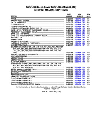
  • 7. 1. COWL PLATE 2. FENDERS 3. HOOD MOUNTS 4. COUNTERWEIGHT MOUNTS 5. HYDRAULIC TANKS Figure 2. Frame for Lift Trucks with Dual Hydraulic Tanks 0100 YRM 1243 Description 3
  • 8. Hood, Seat, and Side Covers Replacement REMOVE 1. Slide seat to the closest position to steering col- umn. 2. Fully tilt steering column forward. 3. If your truck is equipped with an LPG tank, swing tank off to the side. 4. Raise latch on the left, front corner of hood to un- latch and lift up hood. See Figure 3. 5. Remove floor mat and floor plate. See Figure 4. 6. Remove two capscrews holding left and right rear side covers to the frame. Remove rear side cov- ers from frame. See Figure 4. 7. Remove two capscrews holding left and right fender covers to front overhead guard leg. Re- move covers. See Figure 4. 8. Remove four capscrews holding left and right front side covers to frame. Remove covers. 9. Fully lower the steering column. 10. Remove upper steering column cover by pulling up on upper steering column cover to release latches (one on either side), and pulling cover away from steering column. See Figure 5. 11. Remove five fasteners (see Figure 5) securing dash to the top of cowl. Remove four clips, loca- ted underneath dash, that attach dash to the kick panel. Lift to remove dash. 12. Lift kick panel to remove it from truck. See Fig- ure 4. 13. Remove three capscrews holding the seal plate. Remove seal plate. See Figure 6. 14. Disconnect seat wire harness connector. See Fig- ure 3. CAUTION When removing the seat from the hood, DO NOT use an impact wrench to remove the capscrews. Damage can be caused to the threads on the screws and in the holes. 15. If seat is to be removed, and truck is equipped with a non-swivel seat, remove seat wire harness from seat wire harness brackets that are attached to the underside of hood. Remove the cable clips from the seat wire harness. If truck is equipped with a swivel seat, remove seat wire harness from seat wire harness bracket attached to underside of hood and behind the seat. See Figure 3. 16. Remove four capscrews and washers holding seat to the hood. Lift seat off the hood. Pull seat wire harness through hood. See Figure 3. 17. Remove capscrews and washers at top of the gas springs. Remove gas springs from hood. 18. Remove hinge screws, located in the rear of the hood. 19. Lift hood from the truck. See Figure 3. INSTALL 1. Place hood onto the lift truck frame. 2. Install hinge screws, located in the rear of the hood, and tighten to 38 N•m (28 lbf ft). See Fig- ure 3. 3. Align top holes in the gas springs with holes in hood. There are two sets of holes used to install the gas springs to hood, based on the type of seat installed on lift truck. One set is for installing the cylinder end of the gas springs and the other set is for attaching the rod end of the gas springs. In- stall capscrews and washers to attach gas springs to the hood. Refer to Figure 7 and Table 1 for correct holes used to connect the rod end of the cylinder, depending on the type of seat instal- led on the lift truck. Tighten capscrews to 19.2 N•m (170 lbf in). Hood, Seat, and Side Covers Replacement 0100 YRM 1243 4
  • 9. Thank you very much for your reading. Please Click Here. Then Get COMPLETE MANUAL. NO WAITING NOTE: If there is no response to click on the link above, please download the PDF document first and then click on it.
  • 10. NOTE: SWIVEL SEAT AND VENTED HOOD ARE OPTIONAL FEATURES. A. SIDE VIEW OF HOOD AND SEAT B. SIDE VIEW OF HOOD C. BOTTOM VIEW OF HOOD D. SIDE VIEW OF VENTED HOOD WITH SWIVEL SEAT 1. SEAT 2. HOOD 3. FRAME 4. SEAT WIRE HARNESS 5. SEAT WIRE HARNESS CONNECTOR 6. CABLE CLIPS 7. HINGE SCREWS 8. GAS SPRING 9. ATTACHMENT HOLES ATTACHING HOOD TO SEAT (SEMI-SUSPENSION) 10. SEAT WIRE HARNESS BRACKETS 11. SEAT LINER 12. HOOD LATCH 13. ATTACHMENT HOLES ATTACHING HOOD TO SEAT (NON-SUSPENSION) 14. ATTACHMENT HOLES ATTACHING HOOD TO SEAT (FULL SUSPENSION) 15. SPACER 16. FLANGE NUT Figure 3. Hood and Seat Arrangement 0100 YRM 1243 Hood, Seat, and Side Covers Replacement 5
  • 11. 1. UPPER STEERING COLUMN COVER 2. LOWER STEERING COLUMN COVER 3. CAPSCREW 4. DASH ASSEMBLY 5. INSERT 6. SCREW 7. CLIP 8. SEAL 9. GROMMET 10. KICK PANEL 11. LEFT REAR SIDE COVER 12. SEAL PLATE ASSEMBLY 13. FLOOR MAT 14. FLOOR PLATE 15. CLIP NUT 16. FOLDOVER NUT 17. LEFT FENDER COVER 18. LEFT FRONT SIDE COVER 19. LEFT PANEL 20. LEFT STEP PLATE 21. LOCK NUT 22. RIGHT FRONT SIDE COVER 23. RIGHT FENDER COVER 24. RIGHT STEP PLATE 25. RIGHT PANEL 26. RIGHT REAR SIDE COVER 27. SPLASH SHIELD 28. RADIATOR COVER GLC40, 45, 55VX; GLC55SVX; (GC/GLC080, 100, 120VX; GC/ GLC080, 100VXBCS; GC/GLC120SVX; GC/ GLC120VXPRS) (E818, F818) 29. RADIATOR COVER (GLP/GDP40VX5/VX6; GLP/ GDP45SVX5, GLP/GDP45VX6; GLP/ GDP50-55VX (GP/GLP/GDP080, 090, 100, 110, 120VX) (F813, G813, H813, J813) Figure 4. Side Covers, Floor Plate, and Cowl Components Hood, Seat, and Side Covers Replacement 0100 YRM 1243 6
  • 12. NOTE: TOP VIEW OF DASH SHOWN. A. INDICATES TO PULL UP TO UNLATCH 1. ALLEN SCREWS 2. COWL 3. UPPER STEERING COLUMN COVER 4. LOWER STEERING COLUMN COVER Figure 5. Remove Dash From Cowl 0100 YRM 1243 Hood, Seat, and Side Covers Replacement 7
  • 13. 1. CAPSCREWS 2. SEAL PLATE Figure 6. Remove Seal Plate From Dash Hood, Seat, and Side Covers Replacement 0100 YRM 1243 8
  • 14. Figure 7. Gas Spring Installation 0100 YRM 1243 Hood, Seat, and Side Covers Replacement 9
  • 15. Legend for Figure 7 NOTE: SEE TABLE 1 FOR HOLES TO USE TO ATTACH ROD END OF GAS SPRING. A. GLC40, 45, 55VX; GLC55SVX; (GC/GLC080, 100, 120VX; GC/GLC080, 100VXBCS; GC/ GLC120SVX; GC/GLC120VXPRS) (E818, F818) B. GLP/GDP40VX5/VX6; GLP/GDP45SVX5, GLP/ GDP45VX6; GLP/GDP50-55VX (GP/GLP/ GDP080, 090, 100, 110, 120VX) (F813, G813, H813, J813) C. LEFT SIDE D. RIGHT SIDE 1. MOUNTING LOCATION FOR CYLINDER END OF GAS SPRING FOR NON-SUSPENSION SEAT 2. MOUNTING LOCATION FOR CYLINDER END OF GAS SPRING FOR SEMI OR FULL SUSPENSION SEAT Table 1. Gas Spring Installation, Holes for Installing Rod Ends (See Figure 7) Counterweight Type Full or Semi Suspension Seat Non-Suspension Seat Left Side Right Side Left Side Right Side Standard Counterweight GLC40, 45, 50, 55VX (GC/GLC080, 100, 120VX) (E818, F818) 3 3 1 1 Standard Counterweight GLP/ GDP40VX5/VX6; GLP/GDP45SVX5, GLP/GDP45VX6; GLP/GDP50-55VX (GP/GLP/GDP080, 090, 100, 110, 120VX) (F813, G813, H813, J813) 2 2 1 1 BCS and PRS Counterweights GLC55SVX (GC/ GLC080, 100VXBCS, GC/ GLC120SVX; GC/ GLC120VXPRS) (E818, F818) 2 4 2 4 Hood, Seat, and Side Covers Replacement 0100 YRM 1243 10
  • 16. 4. Install latch striker in highest slot position. Check that latch striker is in center of jaws of hood latch when hood closes. Open and close hood to en- sure that center pin strikes hood latch properly and that the stop screw contacts the frame. A properly closed hood MUST click twice on the hood latch. If the hood latch does not close prop- erly, loosen capscrews on the back of center pin and adjust center pin up or down as required for correct alignment. See Figure 8. 5. Push down until hood just touches rubber bumper. Make sure latch striker is still in center of hood latch. Open hood and tighten capscrews for latch. 1. HOOD 2. HOOD LATCH 3. CENTER PIN 4. CAPSCREW Figure 8. Hood Latch Adjustment 6. Check operation of hood latch. Have an operator sit in seat. Make sure hood is fully closed (two clicks). Also check that hood touches rubber bumper. If necessary, repeat Step 5. CAUTION When installing the seat to the hood, DO NOT use an impact wrench to install the capscrews. Dam- age can be caused to the threads on the screws and in the holes. 7. Place seat on the hood and thread seat wire har- ness through the hole in the hood. See Figure 3. 8. Align holes in the seat with the holes in hood. In- sert washers and capscrews. Tighten capscrews to 18 N•m (159 lbf in). 9. If truck is equipped with a non-swivel seat, tie ca- ble clips to seat wire harness and insert harness into seat wire harness brackets under hood. If truck is equipped with a swivel seat, secure seat harness to bracket. See Figure 3. 10. Install seal plate using three capscrews. See Fig- ure 6. 11. Install kick panel onto truck. See Figure 4. 12. Install dash to top of cowl. See Figure 5. Install four clips to attach dash to kick panel. 13. Install upper steering column cover to dash. 14. Using four capscrews, install left and right front side covers to frame. See Figure 4. 15. Using two capscrews, install left and right fender covers to front of overhead guard legs. 16. Using two capscrews, install left and right rear side covers to frame. See Figure 4. 17. Install floor mat and floor plate. 18. If truck is equipped with an LPG tank, swing LPG tank into position on back of counterweight. 19. Adjust the steering column and seat positions. 0100 YRM 1243 Steering Column 11